EP3961558A1 - Image recognition method and image recognition device - Google Patents
Image recognition method and image recognition device Download PDFInfo
- Publication number
- EP3961558A1 EP3961558A1 EP20840239.6A EP20840239A EP3961558A1 EP 3961558 A1 EP3961558 A1 EP 3961558A1 EP 20840239 A EP20840239 A EP 20840239A EP 3961558 A1 EP3961558 A1 EP 3961558A1
- Authority
- EP
- European Patent Office
- Prior art keywords
- image
- restoration
- label
- input
- features
- Prior art date
- Legal status (The legal status is an assumption and is not a legal conclusion. Google has not performed a legal analysis and makes no representation as to the accuracy of the status listed.)
- Pending
Links
Images




Classifications
-
- G—PHYSICS
- G06—COMPUTING OR CALCULATING; COUNTING
- G06V—IMAGE OR VIDEO RECOGNITION OR UNDERSTANDING
- G06V20/00—Scenes; Scene-specific elements
- G06V20/50—Context or environment of the image
- G06V20/56—Context or environment of the image exterior to a vehicle by using sensors mounted on the vehicle
-
- G—PHYSICS
- G06—COMPUTING OR CALCULATING; COUNTING
- G06T—IMAGE DATA PROCESSING OR GENERATION, IN GENERAL
- G06T5/00—Image enhancement or restoration
- G06T5/50—Image enhancement or restoration using two or more images, e.g. averaging or subtraction
-
- G—PHYSICS
- G06—COMPUTING OR CALCULATING; COUNTING
- G06T—IMAGE DATA PROCESSING OR GENERATION, IN GENERAL
- G06T5/00—Image enhancement or restoration
-
- G—PHYSICS
- G06—COMPUTING OR CALCULATING; COUNTING
- G06T—IMAGE DATA PROCESSING OR GENERATION, IN GENERAL
- G06T5/00—Image enhancement or restoration
- G06T5/60—Image enhancement or restoration using machine learning, e.g. neural networks
-
- G—PHYSICS
- G06—COMPUTING OR CALCULATING; COUNTING
- G06T—IMAGE DATA PROCESSING OR GENERATION, IN GENERAL
- G06T7/00—Image analysis
-
- G—PHYSICS
- G06—COMPUTING OR CALCULATING; COUNTING
- G06T—IMAGE DATA PROCESSING OR GENERATION, IN GENERAL
- G06T7/00—Image analysis
- G06T7/10—Segmentation; Edge detection
-
- G—PHYSICS
- G06—COMPUTING OR CALCULATING; COUNTING
- G06T—IMAGE DATA PROCESSING OR GENERATION, IN GENERAL
- G06T7/00—Image analysis
- G06T7/10—Segmentation; Edge detection
- G06T7/174—Segmentation; Edge detection involving the use of two or more images
-
- G—PHYSICS
- G06—COMPUTING OR CALCULATING; COUNTING
- G06V—IMAGE OR VIDEO RECOGNITION OR UNDERSTANDING
- G06V10/00—Arrangements for image or video recognition or understanding
- G06V10/20—Image preprocessing
- G06V10/30—Noise filtering
-
- G—PHYSICS
- G06—COMPUTING OR CALCULATING; COUNTING
- G06V—IMAGE OR VIDEO RECOGNITION OR UNDERSTANDING
- G06V10/00—Arrangements for image or video recognition or understanding
- G06V10/70—Arrangements for image or video recognition or understanding using pattern recognition or machine learning
- G06V10/74—Image or video pattern matching; Proximity measures in feature spaces
-
- G—PHYSICS
- G06—COMPUTING OR CALCULATING; COUNTING
- G06V—IMAGE OR VIDEO RECOGNITION OR UNDERSTANDING
- G06V10/00—Arrangements for image or video recognition or understanding
- G06V10/70—Arrangements for image or video recognition or understanding using pattern recognition or machine learning
- G06V10/77—Processing image or video features in feature spaces; using data integration or data reduction, e.g. principal component analysis [PCA] or independent component analysis [ICA] or self-organising maps [SOM]; Blind source separation
- G06V10/7715—Feature extraction, e.g. by transforming the feature space, e.g. multi-dimensional scaling [MDS]; Mappings, e.g. subspace methods
-
- G—PHYSICS
- G06—COMPUTING OR CALCULATING; COUNTING
- G06V—IMAGE OR VIDEO RECOGNITION OR UNDERSTANDING
- G06V10/00—Arrangements for image or video recognition or understanding
- G06V10/70—Arrangements for image or video recognition or understanding using pattern recognition or machine learning
- G06V10/77—Processing image or video features in feature spaces; using data integration or data reduction, e.g. principal component analysis [PCA] or independent component analysis [ICA] or self-organising maps [SOM]; Blind source separation
- G06V10/80—Fusion, i.e. combining data from various sources at the sensor level, preprocessing level, feature extraction level or classification level
-
- G—PHYSICS
- G06—COMPUTING OR CALCULATING; COUNTING
- G06V—IMAGE OR VIDEO RECOGNITION OR UNDERSTANDING
- G06V10/00—Arrangements for image or video recognition or understanding
- G06V10/70—Arrangements for image or video recognition or understanding using pattern recognition or machine learning
- G06V10/82—Arrangements for image or video recognition or understanding using pattern recognition or machine learning using neural networks
-
- G—PHYSICS
- G06—COMPUTING OR CALCULATING; COUNTING
- G06V—IMAGE OR VIDEO RECOGNITION OR UNDERSTANDING
- G06V20/00—Scenes; Scene-specific elements
- G06V20/50—Context or environment of the image
- G06V20/56—Context or environment of the image exterior to a vehicle by using sensors mounted on the vehicle
- G06V20/588—Recognition of the road, e.g. of lane markings; Recognition of the vehicle driving pattern in relation to the road
-
- G—PHYSICS
- G06—COMPUTING OR CALCULATING; COUNTING
- G06V—IMAGE OR VIDEO RECOGNITION OR UNDERSTANDING
- G06V20/00—Scenes; Scene-specific elements
- G06V20/50—Context or environment of the image
- G06V20/59—Context or environment of the image inside of a vehicle, e.g. relating to seat occupancy, driver state or inner lighting conditions
-
- G—PHYSICS
- G06—COMPUTING OR CALCULATING; COUNTING
- G06V—IMAGE OR VIDEO RECOGNITION OR UNDERSTANDING
- G06V20/00—Scenes; Scene-specific elements
- G06V20/70—Labelling scene content, e.g. deriving syntactic or semantic representations
-
- G—PHYSICS
- G06—COMPUTING OR CALCULATING; COUNTING
- G06T—IMAGE DATA PROCESSING OR GENERATION, IN GENERAL
- G06T2207/00—Indexing scheme for image analysis or image enhancement
- G06T2207/20—Special algorithmic details
- G06T2207/20212—Image combination
- G06T2207/20224—Image subtraction
-
- G—PHYSICS
- G06—COMPUTING OR CALCULATING; COUNTING
- G06V—IMAGE OR VIDEO RECOGNITION OR UNDERSTANDING
- G06V20/00—Scenes; Scene-specific elements
- G06V20/50—Context or environment of the image
- G06V20/56—Context or environment of the image exterior to a vehicle by using sensors mounted on the vehicle
- G06V20/58—Recognition of moving objects or obstacles, e.g. vehicles or pedestrians; Recognition of traffic objects, e.g. traffic signs, traffic lights or roads
-
- G—PHYSICS
- G06—COMPUTING OR CALCULATING; COUNTING
- G06V—IMAGE OR VIDEO RECOGNITION OR UNDERSTANDING
- G06V2201/00—Indexing scheme relating to image or video recognition or understanding
- G06V2201/05—Recognition of patterns representing particular kinds of hidden objects, e.g. weapons, explosives, drugs
-
- G—PHYSICS
- G06—COMPUTING OR CALCULATING; COUNTING
- G06V—IMAGE OR VIDEO RECOGNITION OR UNDERSTANDING
- G06V2201/00—Indexing scheme relating to image or video recognition or understanding
- G06V2201/06—Recognition of objects for industrial automation
-
- G—PHYSICS
- G06—COMPUTING OR CALCULATING; COUNTING
- G06V—IMAGE OR VIDEO RECOGNITION OR UNDERSTANDING
- G06V2201/00—Indexing scheme relating to image or video recognition or understanding
- G06V2201/07—Target detection
-
- G—PHYSICS
- G06—COMPUTING OR CALCULATING; COUNTING
- G06V—IMAGE OR VIDEO RECOGNITION OR UNDERSTANDING
- G06V2201/00—Indexing scheme relating to image or video recognition or understanding
- G06V2201/08—Detecting or categorising vehicles
Definitions
- One aspect of the present invention relates to an image recognition method and an image recognition device.
- Patent Literature 1 As a technique concerning an image recognition method of recognizing a specific image, an information processing apparatus described in Patent Literature 1 has been known, for example.
- the information processing apparatus described in Patent Literature 1 extracts a partial image from an image that was input. The extracted partial image is compared with a partial image that has been already registered, and whether they are similar is determined.
- Patent Literature 1 Japanese Patent No. 5082512
- the image recognition is performed based on whether each image feature of a specific image is included, even if the image can be easily distinguished as an image different from the specific image by human visual observation, it may be erroneously recognized as a specific image when a large number of the same image feature are included.
- An object of one aspect of the present invention is to provide an image recognition method and an image recognition device capable of recognizing a specific image with high accuracy.
- An image recognition method is a method of recognizing a specific image and includes a first step of detecting a plurality of image features from the specific image and storing in a memory each of the detected relevant image features as a part; a second step of detecting a plurality of image features from an input image and selecting from the memory a part corresponding to each of the detected relevant image features; a third step of generating a restoration image by using a plurality of the parts selected in the second step; and a fourth step of determining whether the restoration image generated in the third step matches with the input image by a matching process and recognizing that, when it is determined that the restoration image matches with the input image, the input image is the specific image.
- This image recognition method when generating the restoration image, use the parts detected from the specific image. Consequently, when an image other than the specific image is input as an input image, it is not possible to correctly generate the input image as the restoration image.
- the match or mismatch between the input image and the specific image can be determined with high accuracy. That is, it is possible to recognize the specific image with high accuracy.
- a part label as a label may be given to each of the parts, and the part label may be stored in the memory together with the part, and in the second step, a selection label as a label may be given to each of the image features, and the part of the part label that matches with the selection label may be selected. In this way, the generation process of the restoration image can be efficiently performed.
- the second step may include an image cutting process of cutting out an input image from a captured image as a distance image, and in the image cutting process, a point cloud of a depth distance within a predetermined range in the captured image may be assumed as an object, and an image of the relevant object in the captured image may be cut out as the input image. In this way, the input image can be generated from the captured image.
- a feature intensity of each of the image features may be detected, and in the third step, the restoration image may be generated by further using the plurality of feature intensities detected in the second step. In this way, the restoration image can be accurately generated.
- the specific image may be an image of at least a portion of a vehicle body in a traveling vehicle traveling along a predetermined traveling path.
- the image recognition method according to one aspect of the present invention can be applied to the image recognition of the vehicle body of the traveling vehicle.
- An image recognition device is a device that recognizes a specific image and includes a memory configured to store therein each of a plurality of image features detected from the specific image as a part in advance; a feature detection unit configured to detect a plurality of image features from an input image; a restoration unit configured to select from the memory the part corresponding to each of the relevant image features detected by the feature detection unit and to generate a restoration image by using a plurality of the selected parts; and a determination unit configured to determine whether the restoration image generated in the restoration unit matches with the input image by a matching process and to recognize that, when determines that the restoration image matches with the input image, the input image is the specific image.
- This image recognition device when generating the restoration image, uses the parts detected from the specific image. Consequently, when an image other than the specific image is input as an input image, it is not possible to correctly generate the input image as the restoration image.
- the match or mismatch between the input image and the specific image can be determined with high accuracy. That is, it is possible to recognize the specific image with high accuracy.
- the memory may store therein a label given to each of a plurality of parts as a part label together with the part in advance, the feature detection unit may give a selection label as a label to each of the image features, and the restoration unit may select the part of the part label that matches with the selection label. In this way, the generation process of the restoration image can be efficiently performed.
- the image recognition device may include an image cutting unit configured to cut out the input image from a captured image as a distance image, and the image cutting unit may assume as an object a point cloud of a depth distance within a predetermined range in the captured image and may cut out an image of the relevant object in the captured image as the input image. In this way, the input image can be generated from the captured image.
- the feature detection unit may detect a feature intensity of each of the image features, and the restoration unit may generate the restoration image by further using the plurality of feature intensities detected by the feature detection unit. In this way, the restoration image can be accurately generated.
- the specific image may be an image of at least a portion of a vehicle body in a traveling vehicle traveling along a predetermined traveling path.
- the image recognition device according to one aspect of the present invention can be applied to the image recognition of the vehicle body of the traveling vehicle.
- an image recognition method and an image recognition device capable of recognizing a specific image with high accuracy.
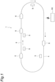
- a traveling vehicle system 1 is a system for transferring, by using a traveling vehicle 6 capable of moving along a track 4, an article 10 between placement portions 9 and 9.
- the article 10 includes a container such as a FOUP (Front Opening Unified Pod) for storing a plurality of semiconductor wafers and a reticle pod for storing a glass substrate, and general components and the like, for example.
- the traveling vehicle system 1 includes the track 4, a plurality of traveling vehicles 6, a plurality of placement portions 9, and a system control unit 60.
- the track 4 is laid near the ceiling that is an overhead space for workers in a factory and the like, for example.
- the track 4 is suspended from the ceiling, for example .
- the track 4 is a predetermined traveling path for traveling the traveling vehicles 6.
- the track 4 is a one-way traveling path, for example.
- the track 4 is supported by supporting columns 40 and 40.
- the traveling vehicle 6 travels along the track 4 and transports the article 10.
- the traveling vehicle 6 is configured such that the article 10 can be transferred.
- the traveling vehicle 6 is an overhead-traveling automatic guided vehicle (overhead traveling vehicle).
- the number of traveling vehicles 6 included in the traveling vehicle system 1 is not particularly limited and is more than one.
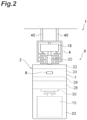
- the traveling vehicle 6 has a vehicle body 2.
- the vehicle body 2 includes a traveling portion 18, a main body portion 7, an imaging unit 8, and a traveling-vehicle control unit 50 (see FIG. 3 ).
- the main body portion 7 has a main body frame 22, a lateral feed portion 24, a ⁇ drive 26, an elevating drive portion 28, an elevating table 30, and a fall prevention cover 33.
- the traveling portion 18 is made up of a motor and the like, and causes the traveling vehicle 6 to travel along the track 4.
- the traveling portion 18 has a power-receiving communication unit 20 that receives power from the track 4 side by a non-contact power supply, for example.
- the lateral feed portion 24 transversely feeds the ⁇ drive 26, the elevating drive portion 28, and the elevating table 30 collectively in a direction perpendicular to the traveling direction of the track 4.
- the ⁇ drive 26 turns at least one of the elevating drive portion 28 and the elevating table 30 within a predetermined angle range inahorizontalplane.
- the elevating drive portion 28 raises and lowers the elevating table 30 by winding or feeding out suspending material such as a wire, a rope, and a belt.
- the elevating table 30 is provided with a chuck, so that the article 10 can be freely grasped or released.
- the fall prevention cover 33 is provided in a pair at the front and rear of the traveling vehicle 6 in the traveling direction, for example. The fall prevention covers 33 prevent the article 10 from falling during transfer by making claws and the like not depicted appear and disappear.
- the placement portions 9 are arranged along the track 4 and are provided at locations where delivery of the article 10 to and from the traveling vehicle 6 can be allowed.
- the placement portions 9 each include a buffer and a delivery port.
- the buffer is a placement portion on which the article 10 is temporarily placed.
- the buffer is a placement portion on which the article 10 is temporarily placed when due to, for example, another article 10 being placed on an intended delivery port and the like, the article 10 that the traveling vehicle 6 is transporting cannot be transferred to the relevant delivery port.
- the delivery port is a placement portion for performing the delivery of the article 10 to and from a semiconductor processing device including a cleaning device, a film-forming device, a lithography device, an etching device, a heat treatment device, and a flattening device.
- the placement portions 9 are arranged on the lateral side of the track 4 .
- the placement portions 9 may be arranged directly below the track 4.
- the imaging unit 8 captures an image of the front of the traveling vehicle 6 itself and acquires a captured image including the traveling vehicle 6 located in front of the traveling vehicle 6 itself.
- the captured image in this case is a distance image.
- the imaging unit 8 is arranged on the fall prevention cover 33 provided on the front side of the traveling vehicle 6.
- the imaging unit 8 transmits the captured image to the traveling-vehicle control unit 50.
- the imaging unit 8 is not particularly limited, and various known devices may be employed.
- the imaging unit 8 may acquire the distance image by a stereo vision method.
- the distance image is also referred to as a three-dimensional distance image or an image having three-dimensional information.
- the traveling-vehicle control unit 50 is an electronic control unit composed of a CPU (Central Processing Unit), a ROM (Read Only Memory), a RAM (Random Access Memory), and the like.
- the traveling-vehicle control unit 50 controls various operations in the traveling vehicle 6. Specifically, the traveling-vehicle control unit 50 controls the traveling portion 18, the lateral feed portion 24, the ⁇ drive 26, the elevating drive portion 28, and the elevating table 30.
- the traveling-vehicle control unit 50 can be configured as software for which a program stored in the ROM is loaded onto the RAM and executed by the CPU, for example.
- the traveling-vehicle control unit 50 may be configured as hardware (computer) by an electronic circuit or the like.
- the traveling-vehicle control unit 50 performs communication with the system control unit 60 by using a communication line (feeder line) and the like of the track 4.
- the system control unit 60 is an electronic control unit composed of a CPU, a ROM, a RAM, and the like.
- the system control unit 60 can be configured as software for which a program stored in the ROM is loaded onto the RAM and executed by the CPU, for example.
- the system control unit 60 may be configured as hardware (computer) by an electronic circuit or the like.
- the system control unit 60 transmits a transport command that causes the traveling vehicle 6 to transport the article 10.
- the system control unit 60 of the present embodiment constitutes an image recognition device 100. The following describes the image recognition device 100. This image recognition device 100 may be provided in the traveling vehicle 6.
- the image recognition device 100 is a device for recognizing a specific image that is a specific image.
- the specific image is an image of the vehicle body 2 of the traveling vehicle 6.
- the image recognition device 100 includes a memory M, an image cutting unit 61, a feature detection unit 62, a restoration unit 63, and a determination unit 64.
- the memory M stores therein each of a plurality of image features detected (extracted) from the specific image as a part in advance.
- the method for detecting image features from the specific image is not particularly limited, and various known methods can be employed. For example, by passing the specific image through an image filter, the image features may be detected.
- the memory M stores therein in advance a label given to each of a plurality of parts together with the part as a part label.
- the part functions, as will be described later, as a seed for image restoration by the restoration unit 63.
- the image feature constitutes the feature of the image and is also referred to as a feature amount or a feature point of the image.
- the acquisition of a plurality of parts may be performed by using a learned model (AI: artificial intelligence) obtainable by deep learning using the L2 norm.
- AI artificial intelligence
- the label indicates information for identifying an object to which the label is given.
- the label is not particularly limited and is, for example, a number.
- the image cutting unit 61 cuts out an input image from the captured image. Specifically, the image cutting unit 61 assumes, as an object (object candidate), a point cloud (a block of points having a similar distance) of the depth distance within a predetermined range in the captured image. The image cutting unit 61 cuts out, as an input image, an image of the relevant object in the captured image.
- the predetermined range is not particularly limited and can be set in advance.
- the cutting of the input image from the captured image may be performed by using a learned model (AI: artificial intelligence) obtainable by deep learning, such as YOLOv3, for example.
- AI artificial intelligence
- the feature detection unit 62 detects a plurality of image features from the input image.
- the method for detecting image features from the input image is not particularly limited, and various known methods can be employed.
- the feature detection unit 62 may detect the image features by passing the input image through an image filter.
- the feature detection unit 62 gives a selection label as a label to each of the image features.
- the feature detection unit 62 detects the feature intensity of each of the image features.
- the feature intensity is an index indicating the strength with which the relevant image feature is related to the input image.
- the feature intensity can indicate the degree that the image feature contributes to in the input image.
- the restoration unit 63 selects from the memory M the part corresponding the image feature.
- the restoration unit 63 selects from the memory M the parts having the part label that matches with the selection label of the image feature detected by the feature detection unit 62.
- the restoration unit 63 generates a restoration image by using a plurality of the selected parts.
- the restoration unit 63 generates the restoration image by further using the feature intensity of the image features detected by the feature detection unit 62.
- the method for generating a restoration image using a plurality of parts is not particularly limited, and various known methods such as an auto-encoder configured with a deep neural network, for example, can be used.
- the determination unit 64 determines whether the restoration image generated in the restoration unit 63 matches with the input image by a matching process.
- the determination unit 64 recognizes that, when it is determined that the restoration image matches with the input image, the input image is the specific image.
- the matching process is not particularly limited, and various known methods such as the L2 norm, for example, can be used.
- the determination unit 64 may calculate the similarity of the restoration image to the input image and determine that, when the relevant similarity is greater than or equal to a threshold value, the restoration image matches with the input image.
- an image of "numeral 7" is used as the input image, for convenience.
- the feature detection unit 62 a plurality of image features are detected from an input image I1.
- an image feature G4 with a selection label LS of "58” are detected.
- these are acquired as an image-feature detection result H.
- the feature intensity of each of the image features G1 to G4 is indicated as brightness. In this way, a plurality of image features G1 to G4 can be mechanically detected from the input image I1.
- the restoration unit 63 based on the image-feature detection result H, parts P1 to P4 of part labels LP matching with the selection labels LS of the image features G1 to G4 (see FIG. 4 ) are selected from the memory M. With the restoration unit 63, a restoration image O1 is generated using a plurality of the selected parts P1 to P4. In this way, the restoration image O1 can be restored from the image features G1 to G4.
- the image recognition method is a method of recognizing a specific image. As illustrated in FIG. 6 , first, a plurality of image features are detected from a specific image, and each of the detected relevant image features is stored in the memory M as a part (storage process: Step S1). In the storage process, the part label as a label is given to each of a plurality of parts, and the part label is stored in the memory M together with the part.
- an input image is cut out by the image cutting unit 61 (image cutting process: Step S2).
- image cutting process a point cloud of the depth distance within a predetermined range in the captured image is assumed as an object, and the image of the relevant object in the captured image is cut out as an input image.
- image-feature detection process a plurality of image features are detected from the input image that has been cut out in the image cutting process.
- image-feature detection process a selection label is given to each of the image features as a label.
- the image-feature detection process the feature intensity of each of the image features is detected.
- a part corresponding to each of the image features detected in the image-feature detection process is selected from the memory M (part selection process: Step S4).
- the part selection process the parts having the part label that matches with the selection label are selected.
- Step S5 a restoration image is generated (restoration process: Step S5).
- the restoration image is generated by further using the plurality of feature intensities detected in the image-feature detection process.
- Step S6 whether the restoration image generated in the restoration process matches with the input image is determined by the matching process. In the determination process, when it is determined that the restoration image matches with the input image, the input image is recognized as the specific image.
- the storage process constitutes the first step
- the image cutting process and the part selection process constitute the second step
- the restoration process constitutes the third step
- the determination process constitutes the fourth step.
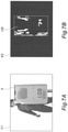
- a captured image K1 including the traveling vehicle 6 located in front of the traveling vehicle 6 itself is acquired.
- depth distance data K2 in the captured image K1 is calculated and a point cloud of the depth distance within a predetermined range is assumed as an object OB.
- the image of the relevant object OB in the captured image K1 is cut out as an input image 12.
- a plurality of image features are detected from the input image I2 by the feature detection unit 62, and a restoration image O2 is generated by the restoration unit 63.
- the determination unit 64 determines whether the restoration image O2 matches with the input image I2 is determined by the matching process. In the example illustrated in FIG. 8(a) and FIG. 8(b) , it is determined that the restoration image O2 matches with the input image I2 (similarity is greater than or equal to the threshold value), and the input image I2 is recognized as the specific image (image of the vehicle body 2 of the traveling vehicle 6).
- FIG. 9(a) when an image other than the vehicle body 2 of the traveling vehicle 6 (for example, an image of a body of a user and the like) is input as an input image 13, as illustrated in FIG. 9(b) , a restoration image O3 generated by the restoration unit 63 is not what the input image I3 has restored, and has significant image collapse and blurring.
- the restoration image O2 does not match with the input image I2 (similarity is below the threshold level), and the input image I3 is not recognized as the specific image (image of the vehicle body 2 of the traveling vehicle 6).
- FIG. 10(a) to FIG. 10(j) are each a diagram for explaining the robustness of the feature detection unit 62 and the restoration unit 63 against noise.
- the image recognition device 100 and the image recognition method thereof it is possible to detect a plurality of image features from an input image 14 (see FIG. 10(a) ) by the feature detection unit 62, and generate a restoration image O4 (see FIG. 10(b) ) by the restoration unit 63.
- a plurality of image features can be detected from an input image I5 (see FIG. 10(c) ) by the feature detection unit 62, and a restoration image O5 (see FIG. 10(d) ) can be generated by the restoration unit 63.
- a plurality of image features can be detected from an input image I6 (see FIG.
- a plurality of image features can be detected from an input image 17 (see FIG. 10(g) ) by the feature detection unit 62, and a restoration image O7 (see FIG. 10(h) ) can be generated by the restoration unit 63.
- a plurality of image features can be detected from an input image I8 (see FIG. 10(i) ) by the feature detection unit 62, and a restoration image O8 (see FIG. 10(j) ) can be generated by the restoration unit 63.
- the above-described units have the ability to capture the features even if the input images I4 to I8 have noise and that the restoration images O4 to O8 are generated accurately.
- the image recognition device 100 and the image recognition method thereof use the parts detected from a specific image when generating a restoration image.
- the image is restored in the patterns illustrated in the following (i), (ii), and (iii).
- determining whether the input images I1 to I8 match with the restoration images O1 to O8 makes it possible to determine the match or mismatch between the input images I1 to 18 and the specific images (whether the input images I1 to I8 are the specific images or other images) with high accuracy. That is, it is possible to recognize the specific image with high accuracy. Determining that the input images I1 to I8 are the specific image if only the image features of the specific image are satisfied will result in misrecognition in the case of the above-described (iii), but the image recognition device 100 and the image recognition method thereof can avoid such misrecognition.
- the part label LP as a label is given to each of a plurality of parts P1 to P4, and the part labels LP are stored in the memory M together with the parts P1 to P4.
- the selection label LS as a label is given to each of a plurality of image features G1 to G4, and the parts P1 to P4 of the part label LP that matches with the selection label LS are selected. In this way, the generation process of the restoration images O1 to O8 can be efficiently performed.
- the input image I2 is cut out from the captured image K1 as a distance image. Specifically, where an object OB is a point cloud of the depth distance within a predetermined range in the captured image K1, the image of the relevant object OB in the captured image K1 is cut out as the input image 12. In this way, the input image 12 can be generated from the captured image K1.
- the feature intensity of each of the image features G1 to G4 is detected, and the restoration images O1 to O8 by further using a plurality of detected feature intensity are generated. In this way, the restoration images O1 to O8 can be accurately generated.
- the specific image is an image of the vehicle body 2 of the traveling vehicle 6.
- the image recognition device 100 and the image recognition method thereof can be applied to the image recognition of the vehicle body 2 of the traveling vehicle 6.
- the specific image may be the entire vehicle body 2 of the traveling vehicle 6 or may be an image of at least a portion of the vehicle body 2 of the traveling vehicle 6.
- the image recognition device 100 may be applied to other various devices or systems, and images of various objects may be designated as specific images.
- the image recognition device 100 may be applied to an automatic winder, and the image of the wound package may be used as a specific image.
- the image recognition device 100 may be applied to a lathe, and by designating an image of a non-defective processed product as a specific image, may be used for determining the quality of the processed product.
- the image recognition device 100 may be used for the cutting of a region of a specific image from an image read by a scanner.
- the input image has been cut out from the captured image as a distance image, but such an image cutting process and an image cutting unit 61 may be not provided.
- the imaging unit 8 a general single-lens camera may be used, for example.
- the input image may be a distance image or may be a two-dimensional image.
- an overhead traveling vehicle has been exemplified as one example of the traveling vehicle 6, but other examples of the traveling vehicle 6 include unmanned vehicles, stacker cranes, and the like that travel on a track laid out on the ground or a frame.
Landscapes
- Engineering & Computer Science (AREA)
- Theoretical Computer Science (AREA)
- General Physics & Mathematics (AREA)
- Physics & Mathematics (AREA)
- Multimedia (AREA)
- Computer Vision & Pattern Recognition (AREA)
- Evolutionary Computation (AREA)
- Computing Systems (AREA)
- Medical Informatics (AREA)
- Software Systems (AREA)
- General Health & Medical Sciences (AREA)
- Databases & Information Systems (AREA)
- Artificial Intelligence (AREA)
- Health & Medical Sciences (AREA)
- Computational Linguistics (AREA)
- Image Analysis (AREA)
- Image Processing (AREA)
Abstract
Description
- One aspect of the present invention relates to an image recognition method and an image recognition device.
- As a technique concerning an image recognition method of recognizing a specific image, an information processing apparatus described in
Patent Literature 1 has been known, for example. The information processing apparatus described inPatent Literature 1 extracts a partial image from an image that was input. The extracted partial image is compared with a partial image that has been already registered, and whether they are similar is determined. - Patent Literature 1:
Japanese Patent No. 5082512 - In the above-described technique, because the image recognition is performed based on whether each image feature of a specific image is included, even if the image can be easily distinguished as an image different from the specific image by human visual observation, it may be erroneously recognized as a specific image when a large number of the same image feature are included.
- An object of one aspect of the present invention is to provide an image recognition method and an image recognition device capable of recognizing a specific image with high accuracy.
- An image recognition method according to one aspect of the present invention is a method of recognizing a specific image and includes a first step of detecting a plurality of image features from the specific image and storing in a memory each of the detected relevant image features as a part; a second step of detecting a plurality of image features from an input image and selecting from the memory a part corresponding to each of the detected relevant image features; a third step of generating a restoration image by using a plurality of the parts selected in the second step; and a fourth step of determining whether the restoration image generated in the third step matches with the input image by a matching process and recognizing that, when it is determined that the restoration image matches with the input image, the input image is the specific image.
- This image recognition method, when generating the restoration image, use the parts detected from the specific image. Consequently, when an image other than the specific image is input as an input image, it is not possible to correctly generate the input image as the restoration image. Thus, by determining whether the input image matches with the restoration image, the match or mismatch between the input image and the specific image (whether the input image is the specific image or other images) can be determined with high accuracy. That is, it is possible to recognize the specific image with high accuracy.
- In the image recognition method according to one aspect of the present invention, in the first step, a part label as a label may be given to each of the parts, and the part label may be stored in the memory together with the part, and in the second step, a selection label as a label may be given to each of the image features, and the part of the part label that matches with the selection label may be selected. In this way, the generation process of the restoration image can be efficiently performed.
- In the image recognition method according to one aspect of the present invention, the second step may include an image cutting process of cutting out an input image from a captured image as a distance image, and in the image cutting process, a point cloud of a depth distance within a predetermined range in the captured image may be assumed as an object, and an image of the relevant object in the captured image may be cut out as the input image. In this way, the input image can be generated from the captured image.
- In the image recognition method according to one aspect of the present invention, in the second step, a feature intensity of each of the image features may be detected, and in the third step, the restoration image may be generated by further using the plurality of feature intensities detected in the second step. In this way, the restoration image can be accurately generated.
- In the image recognition method according to one aspect of the present invention, the specific image may be an image of at least a portion of a vehicle body in a traveling vehicle traveling along a predetermined traveling path. In this case, the image recognition method according to one aspect of the present invention can be applied to the image recognition of the vehicle body of the traveling vehicle.
- An image recognition device according to one aspect of the present invention is a device that recognizes a specific image and includes a memory configured to store therein each of a plurality of image features detected from the specific image as a part in advance; a feature detection unit configured to detect a plurality of image features from an input image; a restoration unit configured to select from the memory the part corresponding to each of the relevant image features detected by the feature detection unit and to generate a restoration image by using a plurality of the selected parts; and a determination unit configured to determine whether the restoration image generated in the restoration unit matches with the input image by a matching process and to recognize that, when determines that the restoration image matches with the input image, the input image is the specific image.
- This image recognition device, when generating the restoration image, uses the parts detected from the specific image. Consequently, when an image other than the specific image is input as an input image, it is not possible to correctly generate the input image as the restoration image. Thus, by determining whether the input image matches with the restoration image, the match or mismatch between the input image and the specific image (whether the input image is the specific image or other images) can be determined with high accuracy. That is, it is possible to recognize the specific image with high accuracy.
- In the image recognition device according to one aspect of the present invention, the memory may store therein a label given to each of a plurality of parts as a part label together with the part in advance, the feature detection unit may give a selection label as a label to each of the image features, and the restoration unit may select the part of the part label that matches with the selection label. In this way, the generation process of the restoration image can be efficiently performed.
- The image recognition device according to one aspect of the present invention may include an image cutting unit configured to cut out the input image from a captured image as a distance image, and the image cutting unit may assume as an object a point cloud of a depth distance within a predetermined range in the captured image and may cut out an image of the relevant object in the captured image as the input image. In this way, the input image can be generated from the captured image.
- In the image recognition device according to one aspect of the present invention, the feature detection unit may detect a feature intensity of each of the image features, and the restoration unit may generate the restoration image by further using the plurality of feature intensities detected by the feature detection unit. In this way, the restoration image can be accurately generated.
- In the image recognition device according to one aspect of the present invention, the specific image may be an image of at least a portion of a vehicle body in a traveling vehicle traveling along a predetermined traveling path. In this case, the image recognition device according to one aspect of the present invention can be applied to the image recognition of the vehicle body of the traveling vehicle.
- According to one aspect of the present invention, it is possible to provide an image recognition method and an image recognition device capable of recognizing a specific image with high accuracy.
-
-
FIG. 1 is a schematic plan view illustrating a traveling vehicle system to which an image recognition device according to one embodiment is applied. -
FIG. 2 is a schematic front view of a traveling vehicle inFIG. 1 as viewed from a traveling direction. -
FIG. 3 is a block diagram illustrating a functional configuration of the traveling vehicle system inFIG. 1 . -
FIG. 4 is a diagram for explaining one example of detecting a plurality of image features from an input image by a feature detection unit of the image recognition device inFIG. 3 . -
FIG. 5 is a diagram for explaining one example of generating a restoration image by a restoration unit of the image recognition device inFIG. 3 . -
FIG. 6 is a flowchart illustrating an image recognition method in the one embodiment. -
FIG. 7 (a) is a diagram illustrating one example of a captured image.FIG. 7(b) is a diagram illustrating one example of depth distance data. -
FIG. 8(a) is a diagram illustrating one example of an input image.FIG. 8(b) is a diagram illustrating a restoration image restored from the input image inFIG. 8(a) . -
FIG. 9(a) is a diagram illustrating one example of an input image.FIG. 9(b) is a diagram illustrating a restoration image restored from the input image inFIG. 9(a) . -
FIG. 10 (a) is a diagram illustrating one example of an input image.FIG. 10(b) is a diagram illustrating a restoration image restored from the input image inFIG. 10 (a). FIG. 10 (c) is a diagram illustrating one example of an input image.FIG. 10 (d) is a diagram illustrating a restoration image restored from the input image inFIG. 10(c). FIG. 10(e) is a diagram illustrating one example of an input image.FIG. 10(f) is a diagram illustrating a restoration image restored from the input image inFIG. 10(e). FIG. 10(g) is a diagram illustrating one example of an input image.FIG. 10(h) is a diagram illustrating a restoration image restored from the input image inFIG. 10(g). FIG. 10(i) is a diagram illustrating one example of an input image.FIG. 10(j) is a diagram illustrating a restoration image restored from the input image inFIG. 10(i) . - With reference to the accompanying drawings, the following describes an exemplary embodiment in detail. In the following description, identical or equivalent constituent elements are denoted by identical reference signs, and redundant explanations are omitted.
- An image recognition device according to the present embodiment is applied to a traveling vehicle system. Thus, the traveling vehicle system will be described first. As illustrated in
FIG. 1 , a travelingvehicle system 1 is a system for transferring, by using a travelingvehicle 6 capable of moving along atrack 4, anarticle 10 betweenplacement portions article 10 includes a container such as a FOUP (Front Opening Unified Pod) for storing a plurality of semiconductor wafers and a reticle pod for storing a glass substrate, and general components and the like, for example. The travelingvehicle system 1 includes thetrack 4, a plurality of travelingvehicles 6, a plurality ofplacement portions 9, and asystem control unit 60. - As illustrated in
FIG. 2 , thetrack 4 is laid near the ceiling that is an overhead space for workers in a factory and the like, for example. Thetrack 4 is suspended from the ceiling, for example . Thetrack 4 is a predetermined traveling path for traveling the travelingvehicles 6. Thetrack 4 is a one-way traveling path, for example. Thetrack 4 is supported by supportingcolumns - The traveling
vehicle 6 travels along thetrack 4 and transports thearticle 10. The travelingvehicle 6 is configured such that thearticle 10 can be transferred. The travelingvehicle 6 is an overhead-traveling automatic guided vehicle (overhead traveling vehicle). The number of travelingvehicles 6 included in the travelingvehicle system 1 is not particularly limited and is more than one. As illustrated inFIG. 2 , the travelingvehicle 6 has avehicle body 2. Thevehicle body 2 includes a travelingportion 18, amain body portion 7, animaging unit 8, and a traveling-vehicle control unit 50 (seeFIG. 3 ). - The
main body portion 7 has amain body frame 22, alateral feed portion 24, aθ drive 26, an elevatingdrive portion 28, an elevating table 30, and afall prevention cover 33. The travelingportion 18 is made up of a motor and the like, and causes the travelingvehicle 6 to travel along thetrack 4. The travelingportion 18 has a power-receivingcommunication unit 20 that receives power from thetrack 4 side by a non-contact power supply, for example. - The
lateral feed portion 24 transversely feeds theθ drive 26, the elevatingdrive portion 28, and the elevating table 30 collectively in a direction perpendicular to the traveling direction of thetrack 4. The θ drive 26 turns at least one of the elevatingdrive portion 28 and the elevating table 30 within a predetermined angle range inahorizontalplane. The elevatingdrive portion 28 raises and lowers the elevating table 30 by winding or feeding out suspending material such as a wire, a rope, and a belt. The elevating table 30 is provided with a chuck, so that thearticle 10 can be freely grasped or released. Thefall prevention cover 33 is provided in a pair at the front and rear of the travelingvehicle 6 in the traveling direction, for example. The fall prevention covers 33 prevent thearticle 10 from falling during transfer by making claws and the like not depicted appear and disappear. - As illustrated in
FIG. 1 andFIG. 2 , theplacement portions 9 are arranged along thetrack 4 and are provided at locations where delivery of thearticle 10 to and from the travelingvehicle 6 can be allowed. Theplacement portions 9 each include a buffer and a delivery port. The buffer is a placement portion on which thearticle 10 is temporarily placed. The buffer is a placement portion on which thearticle 10 is temporarily placed when due to, for example, anotherarticle 10 being placed on an intended delivery port and the like, thearticle 10 that the travelingvehicle 6 is transporting cannot be transferred to the relevant delivery port. The delivery port is a placement portion for performing the delivery of thearticle 10 to and from a semiconductor processing device including a cleaning device, a film-forming device, a lithography device, an etching device, a heat treatment device, and a flattening device. For example, theplacement portions 9 are arranged on the lateral side of thetrack 4 . Theplacement portions 9 may be arranged directly below thetrack 4. - The
imaging unit 8 captures an image of the front of the travelingvehicle 6 itself and acquires a captured image including the travelingvehicle 6 located in front of the travelingvehicle 6 itself. The captured image in this case is a distance image. Theimaging unit 8 is arranged on thefall prevention cover 33 provided on the front side of the travelingvehicle 6. Theimaging unit 8 transmits the captured image to the traveling-vehicle control unit 50. Theimaging unit 8 is not particularly limited, and various known devices may be employed. For example, theimaging unit 8 may acquire the distance image by a stereo vision method. The distance image is also referred to as a three-dimensional distance image or an image having three-dimensional information. - As illustrated in
FIG. 2 andFIG. 3 , the traveling-vehicle control unit 50 is an electronic control unit composed of a CPU (Central Processing Unit), a ROM (Read Only Memory), a RAM (Random Access Memory), and the like. The traveling-vehicle control unit 50 controls various operations in the travelingvehicle 6. Specifically, the traveling-vehicle control unit 50 controls the travelingportion 18, thelateral feed portion 24, theθ drive 26, the elevatingdrive portion 28, and the elevating table 30. The traveling-vehicle control unit 50 can be configured as software for which a program stored in the ROM is loaded onto the RAM and executed by the CPU, for example. The traveling-vehicle control unit 50 may be configured as hardware (computer) by an electronic circuit or the like. The traveling-vehicle control unit 50 performs communication with thesystem control unit 60 by using a communication line (feeder line) and the like of thetrack 4. - The
system control unit 60 is an electronic control unit composed of a CPU, a ROM, a RAM, and the like. Thesystem control unit 60 can be configured as software for which a program stored in the ROM is loaded onto the RAM and executed by the CPU, for example. Thesystem control unit 60 may be configured as hardware (computer) by an electronic circuit or the like. Thesystem control unit 60 transmits a transport command that causes the travelingvehicle 6 to transport thearticle 10. Thesystem control unit 60 of the present embodiment constitutes animage recognition device 100. The following describes theimage recognition device 100. Thisimage recognition device 100 may be provided in the travelingvehicle 6. - The
image recognition device 100 is a device for recognizing a specific image that is a specific image. As one example, the specific image is an image of thevehicle body 2 of the travelingvehicle 6. Theimage recognition device 100 includes a memory M, animage cutting unit 61, afeature detection unit 62, arestoration unit 63, and adetermination unit 64. - The memory M stores therein each of a plurality of image features detected (extracted) from the specific image as a part in advance. The method for detecting image features from the specific image is not particularly limited, and various known methods can be employed. For example, by passing the specific image through an image filter, the image features may be detected. The memory M stores therein in advance a label given to each of a plurality of parts together with the part as a part label. The part functions, as will be described later, as a seed for image restoration by the
restoration unit 63. - The image feature constitutes the feature of the image and is also referred to as a feature amount or a feature point of the image. The acquisition of a plurality of parts may be performed by using a learned model (AI: artificial intelligence) obtainable by deep learning using the L2 norm. The label indicates information for identifying an object to which the label is given. The label is not particularly limited and is, for example, a number.
- The
image cutting unit 61 cuts out an input image from the captured image. Specifically, theimage cutting unit 61 assumes, as an object (object candidate), a point cloud (a block of points having a similar distance) of the depth distance within a predetermined range in the captured image. Theimage cutting unit 61 cuts out, as an input image, an image of the relevant object in the captured image. The predetermined range is not particularly limited and can be set in advance. The cutting of the input image from the captured image may be performed by using a learned model (AI: artificial intelligence) obtainable by deep learning, such as YOLOv3, for example. - The
feature detection unit 62 detects a plurality of image features from the input image. The method for detecting image features from the input image is not particularly limited, and various known methods can be employed. For example, thefeature detection unit 62 may detect the image features by passing the input image through an image filter. Thefeature detection unit 62 gives a selection label as a label to each of the image features. Thefeature detection unit 62 detects the feature intensity of each of the image features. The feature intensity is an index indicating the strength with which the relevant image feature is related to the input image. The feature intensity can indicate the degree that the image feature contributes to in the input image. - On each of the image features detected by the
feature detection unit 62, therestoration unit 63 selects from the memory M the part corresponding the image feature. Therestoration unit 63 selects from the memory M the parts having the part label that matches with the selection label of the image feature detected by thefeature detection unit 62. Therestoration unit 63 generates a restoration image by using a plurality of the selected parts. Therestoration unit 63 generates the restoration image by further using the feature intensity of the image features detected by thefeature detection unit 62. The method for generating a restoration image using a plurality of parts is not particularly limited, and various known methods such as an auto-encoder configured with a deep neural network, for example, can be used. - The
determination unit 64 determines whether the restoration image generated in therestoration unit 63 matches with the input image by a matching process. Thedetermination unit 64 recognizes that, when it is determined that the restoration image matches with the input image, the input image is the specific image. The matching process is not particularly limited, and various known methods such as the L2 norm, for example, can be used. Thedetermination unit 64 may calculate the similarity of the restoration image to the input image and determine that, when the relevant similarity is greater than or equal to a threshold value, the restoration image matches with the input image. - Next, one example of detecting a plurality of image features from the input image by the
feature detection unit 62 will be described with reference toFIG. 4 . - As illustrated in
FIG. 4 , in the description of this case, an image of "numeral 7" is used as the input image, for convenience. With thefeature detection unit 62, a plurality of image features are detected from an input image I1. In the illustrated example, an image feature G1 with a selection label LS of "20", an image feature G2 with a selection label LS of "27", an image feature G3 with a selection label LS of "51", and an image feature G4 with a selection label LS of "58" are detected. Then, these are acquired as an image-feature detection result H. In the image-feature detection result H, the feature intensity of each of the image features G1 to G4 is indicated as brightness. In this way, a plurality of image features G1 to G4 can be mechanically detected from the input image I1. - Next, one example of restoring an image by the
restoration unit 63 based on the image features G1 to G4 will be described with reference toFIG. 5 . - As illustrated in
FIG. 5 , by therestoration unit 63, based on the image-feature detection result H, parts P1 to P4 of part labels LP matching with the selection labels LS of the image features G1 to G4 (seeFIG. 4 ) are selected from the memory M. With therestoration unit 63, a restoration image O1 is generated using a plurality of the selected parts P1 to P4. In this way, the restoration image O1 can be restored from the image features G1 to G4. - Next, an image recognition method that is performed by the
image recognition device 100 will be described. - The image recognition method is a method of recognizing a specific image. As illustrated in
FIG. 6 , first, a plurality of image features are detected from a specific image, and each of the detected relevant image features is stored in the memory M as a part (storage process: Step S1). In the storage process, the part label as a label is given to each of a plurality of parts, and the part label is stored in the memory M together with the part. - Subsequently, from the captured image acquired by the
imaging unit 8, an input image is cut out by the image cutting unit 61 (image cutting process: Step S2). In the image cutting process, a point cloud of the depth distance within a predetermined range in the captured image is assumed as an object, and the image of the relevant object in the captured image is cut out as an input image. - Then, with the
feature detection unit 62, a plurality of image features are detected from the input image that has been cut out in the image cutting process (image-feature detection process: Step S3). In the image-feature detection process, a selection label is given to each of the image features as a label. In the image-feature detection process, the feature intensity of each of the image features is detected. - Subsequently, with the
restoration unit 63, a part corresponding to each of the image features detected in the image-feature detection process is selected from the memory M (part selection process: Step S4). In the part selection process, the parts having the part label that matches with the selection label are selected. - Then, with the
restoration unit 63, by using a plurality of parts selected in the part selection process, a restoration image is generated (restoration process: Step S5). In the restoration process, the restoration image is generated by further using the plurality of feature intensities detected in the image-feature detection process. Finally, by thedetermination unit 64, whether the restoration image generated in the restoration process matches with the input image is determined by the matching process (determination process: Step S6). In the determination process, when it is determined that the restoration image matches with the input image, the input image is recognized as the specific image. - In the foregoing, the storage process constitutes the first step, the image cutting process and the part selection process constitute the second step, the restoration process constitutes the third step, and the determination process constitutes the fourth step.
- Next, one example of recognizing a specific image by the above-described image recognition method will be described. In the following description, a case of recognizing the
vehicle body 2 of the travelingvehicle 6 as the specific image will be exemplified. - As illustrated in
FIG. 7(a) , with theimaging unit 8, a captured image K1 including the travelingvehicle 6 located in front of the travelingvehicle 6 itself is acquired. As illustrated inFIG. 7(b) , with theimage cutting unit 61, depth distance data K2 in the captured image K1 is calculated and a point cloud of the depth distance within a predetermined range is assumed as an object OB. As illustrated inFIG. 7(a) andFIG. 8(a) , the image of the relevant object OB in the captured image K1 is cut out as aninput image 12. - As illustrated in
FIG. 8(b) , a plurality of image features are detected from the input image I2 by thefeature detection unit 62, and a restoration image O2 is generated by therestoration unit 63. With thedetermination unit 64, whether the restoration image O2 matches with the input image I2 is determined by the matching process. In the example illustrated inFIG. 8(a) and FIG. 8(b) , it is determined that the restoration image O2 matches with the input image I2 (similarity is greater than or equal to the threshold value), and the input image I2 is recognized as the specific image (image of thevehicle body 2 of the traveling vehicle 6). - Meanwhile, as illustrated in
FIG. 9(a) , when an image other than thevehicle body 2 of the traveling vehicle 6 (for example, an image of a body of a user and the like) is input as aninput image 13, as illustrated inFIG. 9(b) , a restoration image O3 generated by therestoration unit 63 is not what the input image I3 has restored, and has significant image collapse and blurring. Thus, in this example, it is determined that the restoration image O2 does not match with the input image I2 (similarity is below the threshold level), and the input image I3 is not recognized as the specific image (image of thevehicle body 2 of the traveling vehicle 6). -
FIG. 10(a) to FIG. 10(j) are each a diagram for explaining the robustness of thefeature detection unit 62 and therestoration unit 63 against noise. According to theimage recognition device 100 and the image recognition method thereof, it is possible to detect a plurality of image features from an input image 14 (seeFIG. 10(a) ) by thefeature detection unit 62, and generate a restoration image O4 (seeFIG. 10(b) ) by therestoration unit 63. A plurality of image features can be detected from an input image I5 (seeFIG. 10(c) ) by thefeature detection unit 62, and a restoration image O5 (seeFIG. 10(d) ) can be generated by therestoration unit 63. A plurality of image features can be detected from an input image I6 (seeFIG. 10(e) ) by thefeature detection unit 62, and a restoration image O6 (seeFIG. 10(f) ) can be generated by therestoration unit 63. A plurality of image features can be detected from an input image 17 (seeFIG. 10(g) ) by thefeature detection unit 62, and a restoration image O7 (seeFIG. 10(h) ) can be generated by therestoration unit 63. A plurality of image features can be detected from an input image I8 (seeFIG. 10(i) ) by thefeature detection unit 62, and a restoration image O8 (seeFIG. 10(j) ) can be generated by therestoration unit 63. From these results, it can be confirmed that, according to theimage recognition device 100 and the image recognition method thereof, the above-described units have the ability to capture the features even if the input images I4 to I8 have noise and that the restoration images O4 to O8 are generated accurately. - As in the foregoing, the
image recognition device 100 and the image recognition method thereof use the parts detected from a specific image when generating a restoration image. Thus, the image is restored in the patterns illustrated in the following (i), (ii), and (iii). - (i) When the specific image is an input image, the input image is accurately restored as a restoration image.
- (ii) When an input image other than the specific image is input, the input image and the restoration image do not match.
- (iii) In particular, when an incorrect image that has image features of the specific image but is not the specific image is input as an input image, the specific image is restored as the restoration image while the input image and the restoration image do not match.
- Thus, according to the
image recognition device 100 and the image recognition method thereof, determining whether the input images I1 to I8 match with the restoration images O1 to O8 makes it possible to determine the match or mismatch between the input images I1 to 18 and the specific images (whether the input images I1 to I8 are the specific images or other images) with high accuracy. That is, it is possible to recognize the specific image with high accuracy. Determining that the input images I1 to I8 are the specific image if only the image features of the specific image are satisfied will result in misrecognition in the case of the above-described (iii), but theimage recognition device 100 and the image recognition method thereof can avoid such misrecognition. - In the
image recognition device 100 and the image recognition method thereof, the part label LP as a label is given to each of a plurality of parts P1 to P4, and the part labels LP are stored in the memory M together with the parts P1 to P4. The selection label LS as a label is given to each of a plurality of image features G1 to G4, and the parts P1 to P4 of the part label LP that matches with the selection label LS are selected. In this way, the generation process of the restoration images O1 to O8 can be efficiently performed. - In the
image recognition device 100 and the image recognition method thereof, from the captured image K1 as a distance image, the input image I2 is cut out. Specifically, where an object OB is a point cloud of the depth distance within a predetermined range in the captured image K1, the image of the relevant object OB in the captured image K1 is cut out as theinput image 12. In this way, theinput image 12 can be generated from the captured image K1. - In the
image recognition device 100 and the image recognition method thereof, the feature intensity of each of the image features G1 to G4 is detected, and the restoration images O1 to O8 by further using a plurality of detected feature intensity are generated. In this way, the restoration images O1 to O8 can be accurately generated. - In the
image recognition device 100 and the image recognition method thereof, the specific image is an image of thevehicle body 2 of the travelingvehicle 6. In this case, theimage recognition device 100 and the image recognition method thereof can be applied to the image recognition of thevehicle body 2 of the travelingvehicle 6. The specific image may be theentire vehicle body 2 of the travelingvehicle 6 or may be an image of at least a portion of thevehicle body 2 of the travelingvehicle 6. - As in the foregoing, one exemplary embodiment has been described. However, one aspect of the present invention is not limited to the above-described embodiment, and various modifications can be made without departing from the spirit of the invention.
- In the above-described embodiment, a case where the
image recognition device 100 is applied to the travelingvehicle system 1 and thevehicle body 2 of the travelingvehicle 6 is recognized has been exemplified, but theimage recognition device 100 may be applied to other various devices or systems, and images of various objects may be designated as specific images. For example, theimage recognition device 100 may be applied to an automatic winder, and the image of the wound package may be used as a specific image. For example, theimage recognition device 100 may be applied to a lathe, and by designating an image of a non-defective processed product as a specific image, may be used for determining the quality of the processed product. For example, theimage recognition device 100 may be used for the cutting of a region of a specific image from an image read by a scanner. - In the above-described embodiment, the input image has been cut out from the captured image as a distance image, but such an image cutting process and an
image cutting unit 61 may be not provided. As theimaging unit 8, a general single-lens camera may be used, for example. The input image may be a distance image or may be a two-dimensional image. - In the traveling
vehicle system 1 in the above-described embodiment and modifications, an overhead traveling vehicle has been exemplified as one example of the travelingvehicle 6, but other examples of the travelingvehicle 6 include unmanned vehicles, stacker cranes, and the like that travel on a track laid out on the ground or a frame. -
- 2
- VEHICLE BODY
- 4
- TRACK (TRAVELING PATH)
- 6
- TRAVELING VEHICLE
- 61
- IMAGE CUTTING UNIT
- 62
- FEATURE DETECTION UNIT
- 63
- RESTORATION UNIT
- 64
- DETERMINATION UNIT
- 100
- IMAGE RECOGNITION DEVICE
- G1 to G4
- IMAGE FEATURE
- I1 to I8
- INPUT IMAGE
- K1
- CAPTURED IMAGE
- LS
- SELECTION LABEL
- LP
- PART LABEL
- M
- MEMORY
- O1 to O8
- RESTORATION IMAGE
- OB
- OBJECT
- P1 to P4
- PART
Claims (10)
- An image recognition method of recognizing a specific image, comprising:a first step of detecting a plurality of image features from the specific image and storing in a memory each of the detected relevant image features as a part;a second step of detecting a plurality of image features from an input image and selecting from the memory the part corresponding to each of the detected relevant image features;a third step of generating a restoration image by using a plurality of the parts selected in the second step; anda fourth step of determining whether the restoration image generated in the third step matches with the input image by a matching process and recognizing that, when it is determined that the restoration image matches with the input image, the input image is the specific image.
- The image recognition method according to claim 1, whereinin the first step, a part label as a label is given to each of the parts, and the part label is stored in the memory together with the part, andin the second step, a selection label as a label is given to each of the image features, and the part of the part label that matches with the selection label is selected.
- The image recognition method according to claim 1 or 2, whereinthe second step includes an image cutting process of cutting out an input image from a captured image as a distance image, andin the image cutting process, a point cloud of a depth distance within a predetermined range in the captured image is assumed as an object, and an image of the relevant object in the captured image is cut out as the input image.
- The image recognition method according to any one of claims 1 to 3, whereinin the second step, a feature intensity of each of the image features is detected, andin the third step, the restoration image is generated by further using the plurality of feature intensities detected in the second step.
- The image recognition method according to any one of claims 1 to 4, wherein the specific image is an image of at least a portion of a vehicle body in a traveling vehicle traveling along a predetermined traveling path.
- An image recognition device that recognizes a specific image, comprising:a memory configured to store therein each of a plurality of image features detected from the specific image as a part in advance;a feature detection unit configured to detect a plurality of image features from an input image;a restoration unit configured to select from the memory the part corresponding to each of the relevant image features detected by the feature detection unit and to generate a restoration image by using a plurality of the selected parts; anda determination unit configured to determine whether the restoration image generated in the restoration unit matches with the input image by a matching process and to recognize that, when it is determined that the restoration image matches with the input image, the input image is the specific image.
- The image recognition device according to claim 6, whereinthe memory stores therein a label given to each of a plurality of parts as a part label together with the part in advance,the feature detection unit gives a selection label as a label to each of the image features, andthe restoration unit selects the part of the part label that matches with the selection label.
- The image recognition device according to claim 6 or 7 further comprisingan image cutting unit configured to cut out the input image from a captured image as a distance image, whereinthe image cutting unit assumes as an object a point cloud of a depth distance within a predetermined range in the captured image and cuts out an image of the relevant object in the captured image as the input image.
- The image recognition device according to any one of claims 6 to 8, whereinthe feature detection unit detects a feature intensity of each of the image features, andthe restoration unit generates the restoration image by further using the plurality of feature intensities detected by the feature detection unit.
- The image recognition device according to any one of claims 6 to 9, wherein the specific image is an image of at least a portion of a vehicle body in a traveling vehicle traveling along a predetermined traveling path.
Applications Claiming Priority (2)
| Application Number | Priority Date | Filing Date | Title |
|---|---|---|---|
| JP2019130264 | 2019-07-12 | ||
| PCT/JP2020/016941 WO2021009986A1 (en) | 2019-07-12 | 2020-04-17 | Image recognition method and image recognition device |
Publications (2)
| Publication Number | Publication Date |
|---|---|
| EP3961558A1 true EP3961558A1 (en) | 2022-03-02 |
| EP3961558A4 EP3961558A4 (en) | 2023-01-11 |
Family
ID=74210390
Family Applications (1)
| Application Number | Title | Priority Date | Filing Date |
|---|---|---|---|
| EP20840239.6A Pending EP3961558A4 (en) | 2019-07-12 | 2020-04-17 | IMAGE RECOGNITION METHOD AND IMAGE RECOGNITION DEVICE |
Country Status (8)
| Country | Link |
|---|---|
| US (1) | US11893718B2 (en) |
| EP (1) | EP3961558A4 (en) |
| JP (1) | JP7173344B2 (en) |
| KR (1) | KR102822631B1 (en) |
| CN (1) | CN113728356B (en) |
| IL (1) | IL289320B2 (en) |
| TW (1) | TWI841753B (en) |
| WO (1) | WO2021009986A1 (en) |
Families Citing this family (1)
| Publication number | Priority date | Publication date | Assignee | Title |
|---|---|---|---|---|
| CN116081488B (en) * | 2022-12-21 | 2023-07-04 | 中国矿业大学 | A scene-adaptive monorail crane transportation robot unmanned control method |
Family Cites Families (11)
| Publication number | Priority date | Publication date | Assignee | Title |
|---|---|---|---|---|
| JP5082512B2 (en) | 2007-03-08 | 2012-11-28 | 富士ゼロックス株式会社 | Information processing apparatus, image processing apparatus, image encoding apparatus, information processing program, image processing program, and image encoding program |
| WO2015136714A1 (en) * | 2014-03-14 | 2015-09-17 | オムロン株式会社 | Image recognition device, image sensor, and image recognition method |
| TWI521448B (en) * | 2014-03-18 | 2016-02-11 | Univ Yuan Ze | Vehicle identification system and method |
| TW201618023A (en) * | 2014-11-06 | 2016-05-16 | Charles Chan | Cloud intelligent traffic information method |
| JP6429823B2 (en) | 2016-03-31 | 2018-11-28 | セコム株式会社 | Feature extraction device |
| JP6897335B2 (en) * | 2017-05-31 | 2021-06-30 | 富士通株式会社 | Learning program, learning method and object detector |
| US11282265B2 (en) * | 2017-06-29 | 2022-03-22 | Sony Corporation | Image processing apparatus and image processing method for transmitting data of a 3D model |
| US10942966B2 (en) * | 2017-09-22 | 2021-03-09 | Pinterest, Inc. | Textual and image based search |
| JP7074460B2 (en) * | 2017-11-10 | 2022-05-24 | アズビル株式会社 | Image inspection equipment and methods |
| EP3503038A1 (en) * | 2017-12-22 | 2019-06-26 | Promaton Holding B.V. | Automated 3d root shape prediction using deep learning methods |
| CN109255769A (en) * | 2018-10-25 | 2019-01-22 | 厦门美图之家科技有限公司 | The training method and training pattern and image enchancing method of image enhancement network |
-
2020
- 2020-04-17 WO PCT/JP2020/016941 patent/WO2021009986A1/en not_active Ceased
- 2020-04-17 CN CN202080031205.XA patent/CN113728356B/en active Active
- 2020-04-17 JP JP2021532683A patent/JP7173344B2/en active Active
- 2020-04-17 US US17/623,662 patent/US11893718B2/en active Active
- 2020-04-17 KR KR1020227004074A patent/KR102822631B1/en active Active
- 2020-04-17 IL IL289320A patent/IL289320B2/en unknown
- 2020-04-17 EP EP20840239.6A patent/EP3961558A4/en active Pending
- 2020-07-06 TW TW109122702A patent/TWI841753B/en active
Also Published As
| Publication number | Publication date |
|---|---|
| JP7173344B2 (en) | 2022-11-16 |
| US20220253994A1 (en) | 2022-08-11 |
| IL289320A (en) | 2022-02-01 |
| CN113728356B (en) | 2024-08-23 |
| WO2021009986A1 (en) | 2021-01-21 |
| TW202103057A (en) | 2021-01-16 |
| KR102822631B1 (en) | 2025-06-18 |
| CN113728356A (en) | 2021-11-30 |
| IL289320B2 (en) | 2024-09-01 |
| TWI841753B (en) | 2024-05-11 |
| US11893718B2 (en) | 2024-02-06 |
| KR20220031676A (en) | 2022-03-11 |
| IL289320B1 (en) | 2024-05-01 |
| EP3961558A4 (en) | 2023-01-11 |
| JPWO2021009986A1 (en) | 2021-01-21 |
Similar Documents
| Publication | Publication Date | Title |
|---|---|---|
| CN114241037B (en) | Method and system for picking a target box from a group of multiple boxes | |
| CN107597600B (en) | Sorting system and method for sorting | |
| JP7789616B2 (en) | Object bin picking with rotation compensation | |
| JP7791669B2 (en) | 3D detection of multiple transparent objects | |
| US11964399B2 (en) | Target object recognition device, manipulator, and mobile robot | |
| EP1905548A2 (en) | Workpiece picking apparatus | |
| JP6011490B2 (en) | Goods storage facility | |
| CN109127445B (en) | Bar code reading method and bar code reading system | |
| CN104655017B (en) | A kind of container stacks the measuring system and method for alignment | |
| US9443140B2 (en) | Paper sheets processing apparatus and data transfer method | |
| US11893718B2 (en) | Image recognition method and image recognition device | |
| JP7310889B2 (en) | Running vehicle, running vehicle system, and running vehicle detection method | |
| JP6041710B2 (en) | Image recognition method | |
| CN106429144A (en) | Glass clamping box treatment method, device and system | |
| US20200353583A1 (en) | Workpiece identification method | |
| US20200035056A1 (en) | Paper Sheet Identification System | |
| EP3617967A1 (en) | Taxi system with image based determination of special transportation needs | |
| CN118411586A (en) | Methods for neural network adaptation | |
| KR102953720B1 (en) | Packaging apparatus and packaging method | |
| EP4336299B1 (en) | Traveling vehicle and traveling vehicle system | |
| CN104909151B (en) | A kind of abnormal part processing method of transverse direction, apparatus and system | |
| TW202516465A (en) | Image processing device | |
| CN119500599A (en) | A sorting method, computer storage medium and sorting workstation | |
| JP2024004973A (en) | Determination device, pickup system and determination method | |
| CN120306272A (en) | A parcel sorting method, device, computer storage medium and program product |
Legal Events
| Date | Code | Title | Description |
|---|---|---|---|
| STAA | Information on the status of an ep patent application or granted ep patent |
Free format text: STATUS: THE INTERNATIONAL PUBLICATION HAS BEEN MADE |
|
| PUAI | Public reference made under article 153(3) epc to a published international application that has entered the european phase |
Free format text: ORIGINAL CODE: 0009012 |
|
| STAA | Information on the status of an ep patent application or granted ep patent |
Free format text: STATUS: REQUEST FOR EXAMINATION WAS MADE |
|
| 17P | Request for examination filed |
Effective date: 20211123 |
|
| AK | Designated contracting states |
Kind code of ref document: A1 Designated state(s): AL AT BE BG CH CY CZ DE DK EE ES FI FR GB GR HR HU IE IS IT LI LT LU LV MC MK MT NL NO PL PT RO RS SE SI SK SM TR |
|
| DAV | Request for validation of the european patent (deleted) | ||
| DAX | Request for extension of the european patent (deleted) | ||
| A4 | Supplementary search report drawn up and despatched |
Effective date: 20221208 |
|
| RIC1 | Information provided on ipc code assigned before grant |
Ipc: G06V 20/56 20220101ALI20221202BHEP Ipc: G06V 10/82 20220101ALI20221202BHEP Ipc: G06V 10/30 20220101ALI20221202BHEP Ipc: G06V 10/74 20220101ALI20221202BHEP Ipc: G06T 7/00 20170101AFI20221202BHEP |
|
| STAA | Information on the status of an ep patent application or granted ep patent |
Free format text: STATUS: EXAMINATION IS IN PROGRESS |
|
| 17Q | First examination report despatched |
Effective date: 20240523 |