EP3961240A2 - Aoa/aod calculation in the presence of carrier frequency offset - Google Patents
Aoa/aod calculation in the presence of carrier frequency offset Download PDFInfo
- Publication number
- EP3961240A2 EP3961240A2 EP21193084.7A EP21193084A EP3961240A2 EP 3961240 A2 EP3961240 A2 EP 3961240A2 EP 21193084 A EP21193084 A EP 21193084A EP 3961240 A2 EP3961240 A2 EP 3961240A2
- Authority
- EP
- European Patent Office
- Prior art keywords
- samples
- received
- antenna
- digitized
- signals
- Prior art date
- Legal status (The legal status is an assumption and is not a legal conclusion. Google has not performed a legal analysis and makes no representation as to the accuracy of the status listed.)
- Granted
Links
Images


Classifications
-
- G—PHYSICS
- G01—MEASURING; TESTING
- G01S—RADIO DIRECTION-FINDING; RADIO NAVIGATION; DETERMINING DISTANCE OR VELOCITY BY USE OF RADIO WAVES; LOCATING OR PRESENCE-DETECTING BY USE OF THE REFLECTION OR RERADIATION OF RADIO WAVES; ANALOGOUS ARRANGEMENTS USING OTHER WAVES
- G01S1/00—Beacons or beacon systems transmitting signals having a characteristic or characteristics capable of being detected by non-directional receivers and defining directions, positions, or position lines fixed relatively to the beacon transmitters; Receivers co-operating therewith
- G01S1/02—Beacons or beacon systems transmitting signals having a characteristic or characteristics capable of being detected by non-directional receivers and defining directions, positions, or position lines fixed relatively to the beacon transmitters; Receivers co-operating therewith using radio waves
- G01S1/04—Details
- G01S1/042—Transmitters
-
- G—PHYSICS
- G01—MEASURING; TESTING
- G01S—RADIO DIRECTION-FINDING; RADIO NAVIGATION; DETERMINING DISTANCE OR VELOCITY BY USE OF RADIO WAVES; LOCATING OR PRESENCE-DETECTING BY USE OF THE REFLECTION OR RERADIATION OF RADIO WAVES; ANALOGOUS ARRANGEMENTS USING OTHER WAVES
- G01S3/00—Direction-finders for determining the direction from which infrasonic, sonic, ultrasonic or electromagnetic waves, or particle emission, not having a directional significance, are being received
- G01S3/02—Direction-finders for determining the direction from which infrasonic, sonic, ultrasonic or electromagnetic waves, or particle emission, not having a directional significance, are being received using radio waves
- G01S3/04—Details
- G01S3/10—Means for reducing or compensating for quadrantal, site, or like errors
-
- H—ELECTRICITY
- H04—ELECTRIC COMMUNICATION TECHNIQUE
- H04B—TRANSMISSION
- H04B1/00—Details of transmission systems, not covered by a single one of groups H04B3/00 - H04B13/00; Details of transmission systems not characterised by the medium used for transmission
- H04B1/06—Receivers
- H04B1/16—Circuits
-
- G—PHYSICS
- G01—MEASURING; TESTING
- G01S—RADIO DIRECTION-FINDING; RADIO NAVIGATION; DETERMINING DISTANCE OR VELOCITY BY USE OF RADIO WAVES; LOCATING OR PRESENCE-DETECTING BY USE OF THE REFLECTION OR RERADIATION OF RADIO WAVES; ANALOGOUS ARRANGEMENTS USING OTHER WAVES
- G01S1/00—Beacons or beacon systems transmitting signals having a characteristic or characteristics capable of being detected by non-directional receivers and defining directions, positions, or position lines fixed relatively to the beacon transmitters; Receivers co-operating therewith
- G01S1/02—Beacons or beacon systems transmitting signals having a characteristic or characteristics capable of being detected by non-directional receivers and defining directions, positions, or position lines fixed relatively to the beacon transmitters; Receivers co-operating therewith using radio waves
- G01S1/08—Systems for determining direction or position line
-
- G—PHYSICS
- G01—MEASURING; TESTING
- G01S—RADIO DIRECTION-FINDING; RADIO NAVIGATION; DETERMINING DISTANCE OR VELOCITY BY USE OF RADIO WAVES; LOCATING OR PRESENCE-DETECTING BY USE OF THE REFLECTION OR RERADIATION OF RADIO WAVES; ANALOGOUS ARRANGEMENTS USING OTHER WAVES
- G01S3/00—Direction-finders for determining the direction from which infrasonic, sonic, ultrasonic or electromagnetic waves, or particle emission, not having a directional significance, are being received
- G01S3/02—Direction-finders for determining the direction from which infrasonic, sonic, ultrasonic or electromagnetic waves, or particle emission, not having a directional significance, are being received using radio waves
- G01S3/04—Details
- G01S3/043—Receivers
-
- G—PHYSICS
- G01—MEASURING; TESTING
- G01S—RADIO DIRECTION-FINDING; RADIO NAVIGATION; DETERMINING DISTANCE OR VELOCITY BY USE OF RADIO WAVES; LOCATING OR PRESENCE-DETECTING BY USE OF THE REFLECTION OR RERADIATION OF RADIO WAVES; ANALOGOUS ARRANGEMENTS USING OTHER WAVES
- G01S3/00—Direction-finders for determining the direction from which infrasonic, sonic, ultrasonic or electromagnetic waves, or particle emission, not having a directional significance, are being received
- G01S3/02—Direction-finders for determining the direction from which infrasonic, sonic, ultrasonic or electromagnetic waves, or particle emission, not having a directional significance, are being received using radio waves
- G01S3/14—Systems for determining direction or deviation from predetermined direction
- G01S3/16—Systems for determining direction or deviation from predetermined direction using amplitude comparison of signals derived sequentially from receiving antennas or antenna systems having differently-oriented directivity characteristics or from an antenna system having periodically-varied orientation of directivity characteristic
- G01S3/20—Systems for determining direction or deviation from predetermined direction using amplitude comparison of signals derived sequentially from receiving antennas or antenna systems having differently-oriented directivity characteristics or from an antenna system having periodically-varied orientation of directivity characteristic derived by sampling signal received by an antenna system having periodically-varied orientation of directivity characteristic
-
- H—ELECTRICITY
- H04—ELECTRIC COMMUNICATION TECHNIQUE
- H04B—TRANSMISSION
- H04B1/00—Details of transmission systems, not covered by a single one of groups H04B3/00 - H04B13/00; Details of transmission systems not characterised by the medium used for transmission
- H04B1/02—Transmitters
- H04B1/04—Circuits
-
- H—ELECTRICITY
- H04—ELECTRIC COMMUNICATION TECHNIQUE
- H04B—TRANSMISSION
- H04B7/00—Radio transmission systems, i.e. using radiation field
- H04B7/02—Diversity systems; Multi-antenna system, i.e. transmission or reception using multiple antennas
- H04B7/04—Diversity systems; Multi-antenna system, i.e. transmission or reception using multiple antennas using two or more spaced independent antennas
- H04B7/06—Diversity systems; Multi-antenna system, i.e. transmission or reception using multiple antennas using two or more spaced independent antennas at the transmitting station
-
- H—ELECTRICITY
- H04—ELECTRIC COMMUNICATION TECHNIQUE
- H04B—TRANSMISSION
- H04B7/00—Radio transmission systems, i.e. using radiation field
- H04B7/02—Diversity systems; Multi-antenna system, i.e. transmission or reception using multiple antennas
- H04B7/04—Diversity systems; Multi-antenna system, i.e. transmission or reception using multiple antennas using two or more spaced independent antennas
- H04B7/08—Diversity systems; Multi-antenna system, i.e. transmission or reception using multiple antennas using two or more spaced independent antennas at the receiving station
-
- H—ELECTRICITY
- H04—ELECTRIC COMMUNICATION TECHNIQUE
- H04B—TRANSMISSION
- H04B7/00—Radio transmission systems, i.e. using radiation field
- H04B7/02—Diversity systems; Multi-antenna system, i.e. transmission or reception using multiple antennas
- H04B7/04—Diversity systems; Multi-antenna system, i.e. transmission or reception using multiple antennas using two or more spaced independent antennas
- H04B7/08—Diversity systems; Multi-antenna system, i.e. transmission or reception using multiple antennas using two or more spaced independent antennas at the receiving station
- H04B7/0837—Diversity systems; Multi-antenna system, i.e. transmission or reception using multiple antennas using two or more spaced independent antennas at the receiving station using pre-detection combining
- H04B7/0842—Weighted combining
- H04B7/086—Weighted combining using weights depending on external parameters, e.g. direction of arrival [DOA], predetermined weights or beamforming
-
- G—PHYSICS
- G01—MEASURING; TESTING
- G01S—RADIO DIRECTION-FINDING; RADIO NAVIGATION; DETERMINING DISTANCE OR VELOCITY BY USE OF RADIO WAVES; LOCATING OR PRESENCE-DETECTING BY USE OF THE REFLECTION OR RERADIATION OF RADIO WAVES; ANALOGOUS ARRANGEMENTS USING OTHER WAVES
- G01S3/00—Direction-finders for determining the direction from which infrasonic, sonic, ultrasonic or electromagnetic waves, or particle emission, not having a directional significance, are being received
- G01S3/02—Direction-finders for determining the direction from which infrasonic, sonic, ultrasonic or electromagnetic waves, or particle emission, not having a directional significance, are being received using radio waves
- G01S3/14—Systems for determining direction or deviation from predetermined direction
- G01S3/46—Systems for determining direction or deviation from predetermined direction using antennas spaced apart and measuring phase or time difference between signals therefrom, i.e. path-difference systems
- G01S3/48—Systems for determining direction or deviation from predetermined direction using antennas spaced apart and measuring phase or time difference between signals therefrom, i.e. path-difference systems the waves arriving at the antennas being continuous or intermittent and the phase difference of signals derived therefrom being measured
-
- H—ELECTRICITY
- H01—ELECTRIC ELEMENTS
- H01Q—ANTENNAS, i.e. RADIO AERIALS
- H01Q3/00—Arrangements for changing or varying the orientation or the shape of the directional pattern of the waves radiated from an antenna or antenna system
- H01Q3/24—Arrangements for changing or varying the orientation or the shape of the directional pattern of the waves radiated from an antenna or antenna system varying the orientation by switching energy from one active radiating element to another, e.g. for beam switching
Definitions
- the subject matter described herein relates to determining Angle of Arrival (AoA) or Angle of Departure (AoD), and more particularly to determining AoA or AoD accurately despite carrier frequency offset (CFO).
- AoA Angle of Arrival
- AoD Angle of Departure
- CFO carrier frequency offset
- the receiver circuit includes one or more receiver antennas configured to receive a plurality of RF signals transmitted from a transmitter circuit including one or more transmit antennas, an RF chain configured to generate a plurality of digitized samples of the received RF signals, and a controller configured to receive the digitized samples, to calculate a plurality of additional samples, and to calculate a measured angle of arrival or angle of departure (AoA or AoD) of the RF signals based on the digitized samples and the calculated additional samples.
- AoA or AoD measured angle of arrival or angle of departure
- the RF signals are either transmitted by first and second transmit antennas of the transmitter circuit or are received by first and second receive antennas of the receiver circuit.
- a first set of digitized samples are samples of the RF signals either transmitted by the first transmit antenna of the transmitter circuit or received by the first receive antenna of the receiver circuit
- a second set of digitized samples are samples of the RF signals either transmitted by the second transmit antenna of the transmitter circuit or received by the second receive antenna of the receiver circuit.
- a first set of additional samples is calculated based on the first set of digitized samples, and a second set of additional samples is calculated based on the second set of digitized samples.
- the first set of digitized samples are samples of the RF signals taken at a plurality of first sample times
- the second set of digitized samples are samples of the RF signals taken at a plurality of second sample times
- each of the first sample times is different from each of the second sample times.
- each of the additional samples of the first set of additional samples corresponds with one of the second sample times, and each of the additional samples of the second set of additional samples corresponds with one of the first sample times.
- the controller is configured to calculate the measured AoA or AoD based on the digitized samples and the calculated additional samples corresponding with the plurality of first sample times and corresponding with the plurality of second sample times.
- the RF signals are transmitted by a single transmit antenna of the transmitter circuit and are received by a plurality of receive antennas of the receiver circuit.
- the RF signals are transmitted by a plurality of transmit antennas of the transmitter circuit and are received by a single receive antenna of the receiver circuit.
- the RF chain is selectably connectable to each of a plurality of receive antennas.
- Another inventive aspect is a method of using a receiver circuit, the method including with one or more receiver antennas, receiving a plurality of RF signals transmitted from a transmitter circuit including one or more transmit antennas, with an RF chain, generating a plurality of digitized samples of the received RF signals, with a controller, receiving the digitized samples, with the controller, calculating a plurality of additional samples, and with the controller, calculating a measured angle of arrival or angle of departure (AoA or AoD) of the RF signals based on the digitized samples and the calculated additional samples.
- AoA or AoD measured angle of arrival or angle of departure
- the RF signals are either transmitted by first and second transmit antennas of the transmitter circuit or are received by first and second receive antennas of the receiver circuit.
- a first set of digitized samples are samples of the RF signals either transmitted by the first transmit antenna of the transmitter circuit or received by the first receive antenna of the receiver circuit
- a second set of digitized samples are samples of the RF signals either transmitted by the second transmit antenna of the transmitter circuit or received by the second receive antenna of the receiver circuit.
- a first set of additional samples is calculated based on the first set of digitized samples, and a second set of additional samples is calculated based on the second set of digitized samples.
- the first set of digitized samples are samples of the RF signals taken at a plurality of first sample times
- the second set of digitized samples are samples of the RF signals taken at a plurality of second sample times
- each of the first sample times is different from each of the second sample times.
- each of the additional samples of the first set of additional samples corresponds with one of the second sample times, and each of the additional samples of the second set of additional samples corresponds with one of the first sample times.
- the method further comprises, with the controller, calculating the measured AoA or AoD based on the digitized samples and the calculated additional samples corresponding with the plurality of first sample times and corresponding with the plurality of second sample times.
- the RF signals are transmitted by a single transmit antenna of the transmitter circuit and are received by a plurality of receive antennas of the receiver circuit.
- the RF signals are transmitted by a plurality of transmit antennas of the transmitter circuit and are received by a single receive antenna of the receiver circuit.
- the method further includes, selectably connecting the RF chain to each of a plurality of receive antennas.
- Embodiments illustrate circuits and methods for determining a measured angle of arrival (AoA) or angle of departure (AoD) of a signal received at a receiver circuit having multiple antennas generating signals which are digitized with a single RF chain.
- the AoA or AoD is determined based on a number of signal samples for each of one or more sampling times. Because the RF chain can generate only one sample per sampling time, the other samples for each sampling time are calculated.
- Figures 1A and 1B respectively illustrate schematic diagrams of a receiver circuit and a transmitter circuit.
- Figures 2A and 2B respectively illustrate AoA and AoD.
- Figures 3 and 4 illustrate received and calculated samples used for determining AoA or AoD.
- Figure 5 is a block illustrating a system using an array of N antennas.
- FIG. 1A is a schematic diagram of an embodiment of a transmitter circuit 100 according to an embodiment.
- Transmitter circuit 100 includes antenna or antenna array 110, switch 120, RF chain 130, and controller 140.
- Transmitter circuit 100 illustrates a particular example. Other embodiments of transmitter circuits may be used.
- Antenna or antenna array 110 may be any antenna or antenna array.
- antenna or antenna array 110 includes 1, 2, 3, 4, or more antennas.
- antenna or antenna array 110 includes a linear antenna array.
- antenna or antenna array 110 includes a two dimensional antenna array, for example, having multiple rows of linear antenna arrays.
- antenna or antenna array 110 includes one antenna
- the one antenna may be connected directly to RF chain 130, and switch 120 may be omitted.
- each antenna may be directly connected to a separate RF chain.
- Each of the RF chains may have the features of RF chain 130.
- Antenna or antenna array 110 may be configured to transmit RF signals to a receiver circuit, such as receiver circuit 200 described below with reference to figure 1B .
- the RF signals include a high frequency signal at a carrier frequency modulated with a low frequency information signal.
- the high frequency signal is transmitted by one of the antennas from antenna or antenna array 110, for example, according to a programmable electrical connection formed by switch 120, as controlled by controller 140.
- switch 120 a particular signal transmitted by transmitter circuit 100 may arrive at the receiver after having traversed each of multiple transmission paths. Each of the transmission paths may terminate at the receiver with a different AoA.
- the RF signals transmitted by antenna or antenna array 110 is transmitted from transmitter 100 with an AoD.
- Controller 140 is configured to provide a digital signal to RF chain 130, where the digital signal encodes the information signal to be transmitted by antenna or antenna array 110.
- RF chain 130 includes digital to analog converter (DAC) 132, mixer 136, frequency synthesizer 134, and power amplifier (PA) 138.
- DAC digital to analog converter
- PA power amplifier
- RF chain 130 is an example only, and embodiments of other RF chains may alternatively be used.
- one or more amplifiers, and/or filters may be included, as understood by those of skill in the art.
- the digital signal is processed by the digital to analog converter 132 to generate an analog baseband signal representing the digital signal, using techniques known in the art.
- Various digital to analog converter structures known in the art may be used.
- Mixer 136 receives the analog baseband signal output from the digital to analog converter 132 and an oscillator signal at the carrier frequency generated by frequency synthesizer 134. In response to the analog baseband signal and the oscillator signal, mixer 136 up converts the analog baseband signal from the analog-to-digital converter 132 to a high frequency signal, using techniques known in the art. Various mixer structures known in the art may be used. The resulting high frequency signal is at the carrier frequency in this modulated so as to include the information of the low frequency information signal.
- Power amplifier 138 is configured to receive the high frequency signal the high frequency signal is driven to one of the antennas from antenna or antenna array 110, for example, according to a programmable electrical connection formed by switch 120, as controlled by controller 140.
- the power amplifier 138 drives the high frequency signal to one of the antennas using techniques known in the art. Various power amplifier structures known in the art may be used.
- control signals from controller 140 may control certain variable functionality of switch 120, power amplifier 138, frequency synthesizer 134, mixer 136, and digital to analog converter 132, for example, as understood by those of skill in the art.
- the control signals from controller 140 may, for example, control switch 120 to control which of multiple antennas RF chain 130 drives the high frequency signal with.
- controller 140 may generate control signals for each of the RF chains.
- FIG. 1B is a schematic diagram of an embodiment of a receiver circuit 200 according to an embodiment.
- Receiver circuit 200 includes antenna or antenna array 210, switch 220, RF chain 230, and controller 240.
- Receiver circuit 200 illustrates a particular example. Other embodiments of receiver circuits may be used.
- Antenna or antenna array 210 may be any antenna or antenna array.
- antenna or antenna array 210 includes 1, 2, 3, 4, or more antennas.
- antenna or antenna array 210 includes a linear antenna array.
- antenna or antenna array 210 includes a two dimensional antenna array, for example, having multiple rows of linear antenna arrays.
- antenna or antenna array 210 includes one antenna
- the one antenna may be connected directly to RF chain 230, and switch 220 may be omitted.
- each antenna may be directly connected to a separate RF chain.
- Each of the RF chains may have the features of RF chain 230.
- Antenna or antenna array 210 may be configured to receive RF signals generated by a transmitter, such as transmitter 100 described above with reference to figure 1A . At least because of reflections, a particular signal transmitted by the transmitter may arrive at the antenna or antenna array 210 after having traversed each of multiple transmission paths. Each of the transmission paths may terminate at the antenna or antenna array 210 with a different AoA. Additionally, the RF signals transmitted by the transmitter 100 is transmitted with an AoD.
- RF chain 230 includes low noise amplifier (LNA) 232, frequency synthesizer 234, mixer 236, and analog to digital converter (ADC) 238.
- LNA low noise amplifier
- ADC analog to digital converter
- RF chain 230 is an example only, and embodiments of other RF chains may alternatively be used.
- one or more amplifiers, and/or filters may be included, as understood by those of skill in the art.
- Low noise amplifier 232 is configured to receive a high frequency signal at a carrier frequency and modulated with a low frequency information signal.
- the high frequency signal is received from one of the antennas from antenna or antenna array 210, for example, according to a programmable electrical connection formed by switch 220, as controlled by controller 240.
- the high frequency signal is amplified by low noise amplifier 232 to generate an amplified RF signal, using techniques known in the art.
- Various low noise amplifier structures known in the art may be used.
- Mixer 236 receives the amplified RF signal output from the low noise amplifier 232 and an oscillator signal at or substantially at the carrier frequency generated by frequency synthesizer 234. In response to the amplified RF signal and the oscillator signal, mixer 236 down converts the amplified RF signal from the low noise amplifier 232 to a baseband signal, using techniques known in the art. Various mixer structures known in the art may be used. The resulting baseband signal includes information of the low frequency information signal.
- the baseband signal is then processed by the analog-to-digital converter 238 to generate a digital signal representing the baseband signal, using techniques known in the art.
- analog-to-digital converter structures known in the art may be used.
- Controller 240 receives the digital representation of the baseband signal.
- control signals from controller 240 may control certain variable functionality of switch 220, low noise amplifier 232, frequency synthesizer 234, mixer 236, and analog-to-digital converter 238, for example, as understood by those of skill in the art.
- the control signals from controller 240 may, for example, control switch 220 to select which of multiple antennas RF chain 230 receives the high frequency signals from.
- controller 240 may generate control signals which result in controller 240 receiving a group of digital signals, where each digital signal of the group is generated by RF chain 230 based on a high frequency signal received by a selected one of the antennas.
- controller 240 may generate control signals for each of the RF chains, such that controller 240 receives a group of digital signals, where each digital signal of the group is generated by one of the RF chains based on an RF signal received by the particular antenna connected thereto.
- controller 240 is configured to store the group of digital signals in a memory, and to determine an AoA or AoD for the received RF signals based on the group of digital signals it receives.
- Figure 2A is a schematic diagram illustrating the geometry of phase-based estimation of angle of arrival (AoA) of an RF signal received at an antenna array comprising antenna A1 and antenna A2.
- AoA angle of arrival
- the transmitted RF signal is received at an angle of arrival (AoA) ⁇ at antennas A1 and A2.
- AoA angle of arrival
- ⁇ arccos ⁇ 2 ⁇ d
- a controller such as controller 240 of receiver circuit 200 of figure 1B , may calculate AoA.
- an embodiment of receiver circuit 200 having one RF chain for each of antennas A1 and A2, assuming no carrier frequency offset, may calculate AoA as follows:
- an embodiment of receiver circuit 200 having one RF chain for both antennas A1 and A2, assuming no carrier frequency offset, may calculate AoA as follows:
- ⁇ 2 ⁇ ⁇ 1 ⁇ 2 ⁇ f h t 1 ⁇ t 2 ⁇ 2 ⁇ f l t 1 + T + ⁇ 2 ⁇ ⁇ 2 ⁇ f h t 1 ⁇ t 2 ⁇ 2 ⁇ f l t 1 + ⁇ 1 + 2 ⁇ f l T .
- phase difference for calculating AoA ( ⁇ 2 - ⁇ 1 ) is equal to the phase difference measured + 2 ⁇ f l T
- Figure 2B is a schematic diagram illustrating the geometry of phase-based estimation of angle of departure (AoD) of an RF signal transmitted by an antenna array comprising antenna A1 and antenna A2.
- AoD angle of departure
- the RF signal is transmitted at an angle of departure (AoD) ⁇ from antennas A1 and A2.
- AoD angle of departure
- ⁇ arccos ⁇ 2 ⁇ d
- a controller such as controller 240 of receiver circuit 200 of figure 1B , may calculate AoD.
- an embodiment of receiver circuit 200 having one RF chain and a single antenna A1, assuming no carrier frequency offset, may calculate AoD as follows:
- ⁇ 2 ⁇ ⁇ 1 ⁇ 2 ⁇ f h t 1 ⁇ t 2 ⁇ 2 ⁇ f l t 1 + T + ⁇ 2 ⁇ ⁇ 2 ⁇ f h t 1 ⁇ t 2 ⁇ 2 ⁇ f l t 1 + ⁇ 1 + 2 ⁇ f l T .
- phase difference for calculating AoD ( ⁇ 2 - ⁇ 1 ) is equal to the phase difference measured + 2 ⁇ f l T.
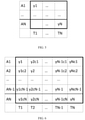
- Figure 3 is a graphic illustration of digitized samples of a received RF signal according to an example embodiment.
- the received RF signal may have been received by a receiver circuit, such as receiver circuit 200 of figure 2 , having first and second receive antennas A1 and A2, and may be used to calculate AoA.
- the received RF signal may have been transmitted by a transmitter circuit, such as transmitter circuit 100 of figure 1 , having first and second transmit antennas A1 and A2, and may be used for calculating AoD.
- antennas A1 and A2 The discussion will refer to antennas A1 and A2. It will be understood, based on the usage context, whether the referenced antennas A1 and A2 are transmit antennas or are receive antennas.
- the received RF signal is received by the receiver circuit, which generates digitized samples of the received RF signal using techniques discussed above and/or other techniques known to those of skill in the art.
- each sampling time T1-T6 has a single digitized sample.
- the receiver circuit generates a digitized sample y1 for the first sampling time T1 based on the received RF signal transmitted or received with antenna A1.
- the receiver circuit generates a digitized sample y2 for the second sampling time T2 based on the received RF signal transmitted or received with antenna A2.
- the receiver circuit generates a digitized sample y3 for the third sampling time T3 based on the received RF signal transmitted or received with antenna A1.
- the receiver circuit generates a digitized sample y4 for the fourth sampling time T4 based on the received RF signal transmitted or received with antenna A2.
- the receiver circuit generates a digitized sample y5 for the fifth sampling time T5 based on the received RF signal transmitted or received with antenna A1.
- the receiver circuit generates a digitized sample y6 for the sixth sampling time T6 based on the received RF signal transmitted or received with antenna A2.
- sampling times may be spaced apart by a switching time, during which, for example, either the transmitter circuit disconnects an amplifier from one of transmit antennas A1 and A2 and connects the amplifier to the other of transmit antennas A1 and A2, or the receiver circuit disconnects an amplifier from one of receive antennas A1 and A2 and connects the amplifier to the other of receive antennas A1 and A2.
- the digital samples generated by the receiver circuit may be used to calculate AoA or AoD. However, because calculations of AoA or AoD are preferably made with digitized samples for the same sampling time, additional digital samples may be calculated based on the digitized samples generated by the RF chain of the receiver circuit.
- Figure 4 is a graphic illustration of received and calculated samples which may be used for calculating AoA or AoD.
- Samples y1 of sampling time T1, y3 of sampling time T3, and y5 of sampling time T5 are generated by the receiver circuit by digitizing the received RF signal of transmit or receive antenna A1 using techniques discussed elsewhere herein, or using other techniques understood by those of skill in the art.
- samples y2 of sampling time T2, y4 of sampling time T4, and y6 of sampling time T6 are generated by the receiver circuit by digitizing the received RF signal of transmit or receive antenna A2 using techniques discussed elsewhere herein, or using other techniques understood by those of skill in the art.
- samples ylc2 of sampling time T1, y2c1 of sampling time T2, y3c2 of sampling time T3, y4c1 of sampling time T4, y5c2 of sampling time T5, and y6c1 of sampling time T6 are calculated by the receiver circuit based on digitized samples of the received RF signal using techniques discussed elsewhere herein, or using other techniques understood by those of skill in the art.
- samples ylc2 of sampling time T1, y3c2 of sampling time T3, and y5c2 of sampling time T5 are calculated based on digitized samples of the received RF signal transmitted or received by antenna A2.
- samples ylc2 of sampling time T1, y3c2 of sampling time T3, and y5c2 of sampling time T5 may be calculated based at least in part on digitized sample y2 of sampling time T2, digitized sample y4 of sampling time T4, and digitized sample y6 of sampling time T6.
- a first digital input signal including digitized sample y2 of sampling time T2, digitized sample y4 of sampling time T4, and digitized sample y6 of sampling time T6 may be input to a digital filter, such as a first digital FIR filter. Any suitable digital FIR filter may be used.
- the first digital FIR filter may oversample the first digital signal input thereto, and may, consequently, generate digital samples corresponding with times between the sampling times of the digitized samples of the first digital input signal.
- the first digital input signal including digitized sample y2 of sampling time T2, digitized sample y4 of sampling time T4, and digitized sample y6 of sampling time T6 may be input to the first digital FIR oversampling by a factor of 2.
- the first digital FIR filter may calculate samples ylc2 of sampling time T1, y3c2 of sampling time T3, and y5c2 of sampling time T5, as illustrated in figure 4 .
- y2c1 of sampling time T2, y4c1 of sampling time T4, and y6c1 of sampling time T6 are calculated based on digitized samples of the received RF signal transmitted or received by antenna A1.
- samples y2c1 of sampling time T2, y4c1 of sampling time T4, and y6c1 of sampling time T6 may be calculated based on digitized sample y1 of sampling time T1, digitized sample y3 of sampling time T3, and digitized sample y5 of sampling time T5.
- a second digital input signal including digitized sample y1 of sampling time T1, digitized sample y3 of sampling time T3, and digitized sample y5 of sampling time T5 may be input to a digital filter, such as a second digital FIR filter. Any suitable digital FIR filter may be used.
- the second digital FIR filter may oversample the digital signal input thereto, and may, consequently, generate digital samples corresponding with times between the sampling times of the digitized samples of the second digital input signal.
- the second digital input signal including digitized sample y1 of sampling time T1, digitized sample y3 of sampling time T3, and digitized sample y5 of sampling time T5 may be input to the second digital FIR oversampling by a factor of 2.
- the digital FIR filter may calculate samples y2c1 of sampling time T2, y4c1 of sampling time T4, and y6c1 of sampling time T6, as illustrated in figure 4 .
- the receiver circuit may calculate a measured AoA or AoD based on the digitized and calculated samples illustrated in figure 4 .
- a measured AoA or AoD may be calculated based on the digitized and calculated samples of multiple sampling times according to, for example, a Multiple Signal Classification (MUSIC) AoA or AoD algorithm, as understood by those of skill in the art.
- MUSIC Multiple Signal Classification
- an estimate of AoA or AoD may be calculated for each sampling time. For example, each of sample pairs y1 and ylc2, y2c1 and y2, y3 and y3c2, y4c1 and y4, y5 and y5c2, and y6c1 and y6 may be used to calculate an estimate of AoA or AoD.
- the calculated estimates of AoA or AoD may be used to calculate a measured AoA or AoD using any of the techniques described herein and/or any other techniques known to those of skill in the art. For example, the measured AoA or AoD may be calculated as an average of the estimates of AoA or AoD.
- Figure 5 is a graphic illustration of digitized samples of a received RF signal according to an example embodiment.
- the received RF signal may have been received by a receiver circuit, such as receiver circuit 200 of figure 2 , having receive antennas A1-AN, and may be used to calculate AoA.
- the received RF signal may have been transmitted by a transmitter circuit, such as transmitter circuit 100 of figure 1 , having antennas A1-AN, and may be used for calculating AoD.
- antennas A1-AN The discussion will refer to antennas A1-AN. It will be understood, based on the usage context, whether the referenced antennas A1-AN are transmit antennas or are receive antennas.
- the received RF signal is received by the receiver circuit, which generates digitized samples of the received RF signal using techniques discussed above and/or other techniques known to those of skill in the art.
- each sampling time T1-TN has a single digitized sample.
- the receiver circuit generates a digitized sample y1 for the first sampling time T1 based on the received RF signal transmitted or received with antenna A1.
- the receiver circuit generates a digitized sample yN for the Nth sampling time TN based on the received RF signal transmitted or received with antenna AN.
- the receiver circuit generates another digitized sample yx for each of the other sampling times Tx between T1 and TN based on the received RF signal transmitted or received with an antenna Ax.
- the receiver circuit continues to generate samples based on the received RF signal with a repeating pattern of the sample generation scheme illustrated in figure 5 .
- sampling times may be spaced apart by a switching time, during which, for example, either the transmitter circuit disconnects an amplifier from one of the transmit antennas A1-AN and connects the amplifier to a next transmit antenna, or the receiver circuit disconnects an amplifier from one of receive antennas A1-AN and connects the amplifier to a next receive antennas.
- the digital samples generated by the receiver circuit may be used to calculate AoA or AoD. However, because calculations of AoA or AoD are preferably made with digitized samples for the same sampling time, additional digital samples may be calculated based on the digitized samples generated by the RF chain of the receiver circuit.
- Figure 6 is a graphic illustration of received and calculated samples which may be used for calculating AoA or AoD.
- the receiver circuit generates a digitized sample y1 for the first sampling time T1 based on the received RF signal transmitted or received with antenna A1.
- the receiver circuit generates a digitized sample y2 for the second sampling time T2 based on the received RF signal transmitted or received with antenna A2.
- the receiver circuit also generates a digitized sample yN-1 for the N-1th sampling time TN-1 based on the received RF signal transmitted or received with antenna AN-1.
- the receiver circuit also generates a digitized sample yN for the Nth sampling time TN based on the received RF signal transmitted or received with antenna AN.
- the receiver circuit generates another digitized sample yx for each of the other sampling times Tx between sampling times T2 and TN-1 based on the received RF signal transmitted or received with an antenna Ax between antennas A2 and AN-1. As understood by those of skill in the art, the receiver circuit continues to generate samples based on the received RF signal with a repeating pattern of the sample generation scheme illustrated in figure 6 .
- samples ylc2-ylcN of sampling time T1, y2c1, y2cN-1, and y2cN of sampling time T2, yN-1c1, yN-1c2, and yN to 1cN of sampling time TN-1, yNc1 to yNcN-1 of sampling time TN, and other samples corresponding with the antennas and sampling times not identified in figure 6 are calculated by the receiver circuit based on digitized samples of the received RF signal using techniques discussed elsewhere herein, or using other techniques understood by those of skill in the art.
- the samples corresponding with each particular antenna are calculated based on digitized samples calculated based on the RF signal transmitted or received by the particular antenna.
- the samples corresponding with antenna Ax are calculated based on digitized samples calculated based on the RF signal transmitted or received by antenna Ax.
- a first digital input signal including digitized sample y1 of sampling time T1 and other digitized samples (not shown) calculated based on the RF signal transmitted or received by antenna A1, for example, of sampling times TN+1, T2N+1, etc. (not shown) may be input to a digital filter, such as a first digital FIR filter. Any suitable digital FIR filter may be used.
- the first digital FIR filter may oversample the first digital signal input thereto, and may, consequently, generate digital samples corresponding with times between the sampling times of the digitized samples of the first digital input signal.
- the first digital input signal including digitized sample y1 of sampling time T1 and the other digitized samples may be input to the first digital FIR oversampling by a factor of N.
- the first digital FIR filter may calculate samples y2c1 - yNc1 of sampling times T2-TN, as illustrated in figure 6 .
- an xth digital input signal including digitized sample yx of sampling time Tx, and other digitized samples (not shown) calculated based on the RF signal transmitted or received by antenna Ax, for example, of sampling times TN+x, T2N+x, etc. (not shown) may be input to a digital filter, such as a first digital FIR filter. Any suitable digital FIR filter may be used.
- the xth digital FIR filter may oversample the digital signal input thereto, and may, consequently, generate digital samples corresponding with times between the sampling times of the digitized samples of the xth digital input signal.
- the xth digital input signal including digitized sample yx of sampling time Tx and the other digitized samples may be input to the xth digital FIR oversampling by a factor of N.
- the xth digital FIR filter may calculate samples for sampling times T1 to Tx-1 and Tx+1 to TN, as illustrated in figure 6 .
- N digital filters may be used to calculate samples to be used with the digitized samples of figure 5 .
- the receiver circuit may calculate a measured AoA or AoD based on the digitized and calculated samples illustrated in figure 6 .
- a measured AoA or AoD may be calculated based on the digitized and calculated samples according to a Multiple Signal Classification (MUSIC) AoA or AoD algorithm, as understood by those of skill in the art.
- MUSIC Multiple Signal Classification
- an estimate of AoA or AoD may be calculated for each sampling time.
- the calculated estimates of AoA or AoD may be used to calculate a measured AoA or AoD using any of the techniques described herein and/or any other techniques known to those of skill in the art.
- the measured AoA or AoD may be calculated as an average of the estimates of AoA or AoD.
- phrases such as "at least one of' or “one or more of' may occur followed by a conjunctive list of elements or features.
- the term “and/or” may also occur in a list of two or more elements or features. Unless otherwise implicitly or explicitly contradicted by the context in which it used, such a phrase is intended to mean any of the listed elements or features individually or any of the recited elements or features in combination with any of the other recited elements or features.
- the phrases “at least one of A and B;” “one or more of A and B;” and “A and/or B” are each intended to mean "A alone, B alone, or A and B together.”
- a similar interpretation is also intended for lists including three or more items.
- phrases “at least one of A, B, and C;” “one or more of A, B, and C;” and “A, B, and/or C” are each intended to mean “A alone, B alone, C alone, A and B together, A and C together, B and C together, or A and B and C together.”
- Use of the term “based on,” above and in the claims is intended to mean, “based at least in part on,” such that an unrecited feature or element is also permissible.
Landscapes
- Engineering & Computer Science (AREA)
- Computer Networks & Wireless Communication (AREA)
- Signal Processing (AREA)
- Physics & Mathematics (AREA)
- General Physics & Mathematics (AREA)
- Radar, Positioning & Navigation (AREA)
- Remote Sensing (AREA)
- Radio Transmission System (AREA)
- Radar Systems Or Details Thereof (AREA)
- Circuits Of Receivers In General (AREA)
Abstract
Description
- The subject matter described herein relates to determining Angle of Arrival (AoA) or Angle of Departure (AoD), and more particularly to determining AoA or AoD accurately despite carrier frequency offset (CFO).
- RF signals transmitted from a transmitter circuit based on a high carrier frequency oscillator are frequently received at a receiver circuit based on a local high carrier frequency oscillator, where the carrier frequency of the transmitter oscillator and the carrier frequency of the receiver oscillator are slightly different. The carrier frequency offset (CFO) causes errors in traditional techniques for determining AoA or AoD. Techniques for accurately calculating AoA or AoD in the presence of CFO are needed in the art.
- One inventive aspect is a receiver circuit. The receiver circuit includes one or more receiver antennas configured to receive a plurality of RF signals transmitted from a transmitter circuit including one or more transmit antennas, an RF chain configured to generate a plurality of digitized samples of the received RF signals, and a controller configured to receive the digitized samples, to calculate a plurality of additional samples, and to calculate a measured angle of arrival or angle of departure (AoA or AoD) of the RF signals based on the digitized samples and the calculated additional samples.
- In some embodiments, the RF signals are either transmitted by first and second transmit antennas of the transmitter circuit or are received by first and second receive antennas of the receiver circuit.
- In some embodiments, a first set of digitized samples are samples of the RF signals either transmitted by the first transmit antenna of the transmitter circuit or received by the first receive antenna of the receiver circuit, and a second set of digitized samples are samples of the RF signals either transmitted by the second transmit antenna of the transmitter circuit or received by the second receive antenna of the receiver circuit.
- In some embodiments, a first set of additional samples is calculated based on the first set of digitized samples, and a second set of additional samples is calculated based on the second set of digitized samples.
- In some embodiments, the first set of digitized samples are samples of the RF signals taken at a plurality of first sample times, the second set of digitized samples are samples of the RF signals taken at a plurality of second sample times, and each of the first sample times is different from each of the second sample times.
- In some embodiments, each of the additional samples of the first set of additional samples corresponds with one of the second sample times, and each of the additional samples of the second set of additional samples corresponds with one of the first sample times.
- In some embodiments, the controller is configured to calculate the measured AoA or AoD based on the digitized samples and the calculated additional samples corresponding with the plurality of first sample times and corresponding with the plurality of second sample times.
- In some embodiments, the RF signals are transmitted by a single transmit antenna of the transmitter circuit and are received by a plurality of receive antennas of the receiver circuit.
- In some embodiments, the RF signals are transmitted by a plurality of transmit antennas of the transmitter circuit and are received by a single receive antenna of the receiver circuit.
- In some embodiments, the RF chain is selectably connectable to each of a plurality of receive antennas.
- Another inventive aspect is a method of using a receiver circuit, the method including with one or more receiver antennas, receiving a plurality of RF signals transmitted from a transmitter circuit including one or more transmit antennas, with an RF chain, generating a plurality of digitized samples of the received RF signals, with a controller, receiving the digitized samples, with the controller, calculating a plurality of additional samples, and with the controller, calculating a measured angle of arrival or angle of departure (AoA or AoD) of the RF signals based on the digitized samples and the calculated additional samples.
- In some embodiments, the RF signals are either transmitted by first and second transmit antennas of the transmitter circuit or are received by first and second receive antennas of the receiver circuit.
- In some embodiments, a first set of digitized samples are samples of the RF signals either transmitted by the first transmit antenna of the transmitter circuit or received by the first receive antenna of the receiver circuit, and a second set of digitized samples are samples of the RF signals either transmitted by the second transmit antenna of the transmitter circuit or received by the second receive antenna of the receiver circuit.
- In some embodiments, a first set of additional samples is calculated based on the first set of digitized samples, and a second set of additional samples is calculated based on the second set of digitized samples.
- In some embodiments, the first set of digitized samples are samples of the RF signals taken at a plurality of first sample times, the second set of digitized samples are samples of the RF signals taken at a plurality of second sample times, and each of the first sample times is different from each of the second sample times.
- In some embodiments, each of the additional samples of the first set of additional samples corresponds with one of the second sample times, and each of the additional samples of the second set of additional samples corresponds with one of the first sample times.
- In some embodiments, the method further comprises, with the controller, calculating the measured AoA or AoD based on the digitized samples and the calculated additional samples corresponding with the plurality of first sample times and corresponding with the plurality of second sample times.
- In some embodiments, the RF signals are transmitted by a single transmit antenna of the transmitter circuit and are received by a plurality of receive antennas of the receiver circuit.
- In some embodiments, the RF signals are transmitted by a plurality of transmit antennas of the transmitter circuit and are received by a single receive antenna of the receiver circuit.
- In some embodiments, the method further includes, selectably connecting the RF chain to each of a plurality of receive antennas.
- The accompanying drawings, which are incorporated in and constitute a part of this specification, show certain aspects of the subject matter disclosed herein and, together with the description, help explain some of the principles associated with the disclosed implementations.
-
Figure 1A is a schematic diagram of an embodiment of a transmitter circuit according to an embodiment. -
Figure 1B is a schematic diagram of an embodiment of a receiver circuit according to an embodiment. -
Figure 2A is a schematic diagram of two antenna systems illustrating AoA. -
Figure 2B is a schematic diagram of two antenna systems illustrating AoD. -
Figure 3 is a graphic illustration of received samples used for calculating AoA or AoD. -
Figure 4 is a graphic illustration of received and calculated samples used for calculating AoA or AoD. -
Figure 5 is a graphic illustration of received samples used for calculating AoA or AoD. -
Figure 6 is a graphic illustration of received and calculated samples used for calculating AoA or AoD. - When practical, similar reference numbers denote similar structures, features, or elements.
- Particular embodiments of the disclosure are illustrated herein in conjunction with the drawings. Particular embodiments of the disclosure are illustrated herein in conjunction with the drawings.
- Various details are set forth herein as they relate to certain embodiments. However, the disclosure can also be implemented in ways which are different from those described herein. Modifications can be made to the discussed embodiments by those skilled in the art without departing from the disclosure. Therefore, the disclosure is not limited to particular embodiments disclosed herein.
- Embodiments illustrate circuits and methods for determining a measured angle of arrival (AoA) or angle of departure (AoD) of a signal received at a receiver circuit having multiple antennas generating signals which are digitized with a single RF chain. The AoA or AoD is determined based on a number of signal samples for each of one or more sampling times. Because the RF chain can generate only one sample per sampling time, the other samples for each sampling time are calculated.
Figures 1A and 1B respectively illustrate schematic diagrams of a receiver circuit and a transmitter circuit.Figures 2A and 2B respectively illustrate AoA and AoD.Figures 3 and 4 illustrate received and calculated samples used for determining AoA or AoD.Figure 5 is a block illustrating a system using an array of N antennas. -
Figure 1A is a schematic diagram of an embodiment of atransmitter circuit 100 according to an embodiment.Transmitter circuit 100 includes antenna orantenna array 110,switch 120,RF chain 130, andcontroller 140.Transmitter circuit 100 illustrates a particular example. Other embodiments of transmitter circuits may be used. - Antenna or
antenna array 110 may be any antenna or antenna array. For example, in some embodiments, antenna orantenna array 110 includes 1, 2, 3, 4, or more antennas. In some embodiments, antenna orantenna array 110 includes a linear antenna array. In some embodiments, antenna orantenna array 110 includes a two dimensional antenna array, for example, having multiple rows of linear antenna arrays. - In embodiments where antenna or
antenna array 110 includes one antenna, the one antenna may be connected directly toRF chain 130, andswitch 120 may be omitted. In embodiments where antenna orantenna array 110 includes multiple antennas, each antenna may be directly connected to a separate RF chain. Each of the RF chains may have the features ofRF chain 130. - Antenna or
antenna array 110 may be configured to transmit RF signals to a receiver circuit, such asreceiver circuit 200 described below with reference tofigure 1B . The RF signals include a high frequency signal at a carrier frequency modulated with a low frequency information signal. The high frequency signal is transmitted by one of the antennas from antenna orantenna array 110, for example, according to a programmable electrical connection formed byswitch 120, as controlled bycontroller 140. At least because of reflections, a particular signal transmitted bytransmitter circuit 100 may arrive at the receiver after having traversed each of multiple transmission paths. Each of the transmission paths may terminate at the receiver with a different AoA. Additionally, the RF signals transmitted by antenna orantenna array 110 is transmitted fromtransmitter 100 with an AoD. -
Controller 140 is configured to provide a digital signal toRF chain 130, where the digital signal encodes the information signal to be transmitted by antenna orantenna array 110. -
RF chain 130 includes digital to analog converter (DAC) 132,mixer 136,frequency synthesizer 134, and power amplifier (PA) 138.RF chain 130 is an example only, and embodiments of other RF chains may alternatively be used. For example, in some embodiments, one or more amplifiers, and/or filters may be included, as understood by those of skill in the art. - The digital signal is processed by the digital to
analog converter 132 to generate an analog baseband signal representing the digital signal, using techniques known in the art. Various digital to analog converter structures known in the art may be used. -
Mixer 136 receives the analog baseband signal output from the digital toanalog converter 132 and an oscillator signal at the carrier frequency generated byfrequency synthesizer 134. In response to the analog baseband signal and the oscillator signal,mixer 136 up converts the analog baseband signal from the analog-to-digital converter 132 to a high frequency signal, using techniques known in the art. Various mixer structures known in the art may be used. The resulting high frequency signal is at the carrier frequency in this modulated so as to include the information of the low frequency information signal. -
Power amplifier 138 is configured to receive the high frequency signal the high frequency signal is driven to one of the antennas from antenna orantenna array 110, for example, according to a programmable electrical connection formed byswitch 120, as controlled bycontroller 140. Thepower amplifier 138 drives the high frequency signal to one of the antennas using techniques known in the art. Various power amplifier structures known in the art may be used. - As understood by those of skill in the art, using communication connectivity not illustrated in
figure 1A , control signals fromcontroller 140 may control certain variable functionality ofswitch 120,power amplifier 138,frequency synthesizer 134,mixer 136, and digital toanalog converter 132, for example, as understood by those of skill in the art. - The control signals from
controller 140 may, for example,control switch 120 to control which of multipleantennas RF chain 130 drives the high frequency signal with. - In embodiments having multiple antennas each connected to one of multiple RF chains,
controller 140 may generate control signals for each of the RF chains. -
Figure 1B is a schematic diagram of an embodiment of areceiver circuit 200 according to an embodiment.Receiver circuit 200 includes antenna orantenna array 210,switch 220,RF chain 230, andcontroller 240.Receiver circuit 200 illustrates a particular example. Other embodiments of receiver circuits may be used. - Antenna or
antenna array 210 may be any antenna or antenna array. For example, in some embodiments, antenna orantenna array 210 includes 1, 2, 3, 4, or more antennas. In some embodiments, antenna orantenna array 210 includes a linear antenna array. In some embodiments, antenna orantenna array 210 includes a two dimensional antenna array, for example, having multiple rows of linear antenna arrays. - In embodiments where antenna or
antenna array 210 includes one antenna, the one antenna may be connected directly toRF chain 230, and switch 220 may be omitted. In embodiments where antenna orantenna array 210 includes multiple antennas, each antenna may be directly connected to a separate RF chain. Each of the RF chains may have the features ofRF chain 230. - Antenna or
antenna array 210 may be configured to receive RF signals generated by a transmitter, such astransmitter 100 described above with reference tofigure 1A . At least because of reflections, a particular signal transmitted by the transmitter may arrive at the antenna orantenna array 210 after having traversed each of multiple transmission paths. Each of the transmission paths may terminate at the antenna orantenna array 210 with a different AoA. Additionally, the RF signals transmitted by thetransmitter 100 is transmitted with an AoD. -
RF chain 230 includes low noise amplifier (LNA) 232,frequency synthesizer 234,mixer 236, and analog to digital converter (ADC) 238.RF chain 230 is an example only, and embodiments of other RF chains may alternatively be used. For example, in some embodiments, one or more amplifiers, and/or filters may be included, as understood by those of skill in the art. -
Low noise amplifier 232 is configured to receive a high frequency signal at a carrier frequency and modulated with a low frequency information signal. The high frequency signal is received from one of the antennas from antenna orantenna array 210, for example, according to a programmable electrical connection formed byswitch 220, as controlled bycontroller 240. The high frequency signal is amplified bylow noise amplifier 232 to generate an amplified RF signal, using techniques known in the art. Various low noise amplifier structures known in the art may be used. -
Mixer 236 receives the amplified RF signal output from thelow noise amplifier 232 and an oscillator signal at or substantially at the carrier frequency generated byfrequency synthesizer 234. In response to the amplified RF signal and the oscillator signal,mixer 236 down converts the amplified RF signal from thelow noise amplifier 232 to a baseband signal, using techniques known in the art. Various mixer structures known in the art may be used. The resulting baseband signal includes information of the low frequency information signal. - The baseband signal is then processed by the analog-to-
digital converter 238 to generate a digital signal representing the baseband signal, using techniques known in the art. Various analog-to-digital converter structures known in the art may be used. -
Controller 240 receives the digital representation of the baseband signal. - As understood by those of skill in the art, using communication connectivity not illustrated in
figure 1B , control signals fromcontroller 240 may control certain variable functionality ofswitch 220,low noise amplifier 232,frequency synthesizer 234,mixer 236, and analog-to-digital converter 238, for example, as understood by those of skill in the art. - The control signals from
controller 240 may, for example,control switch 220 to select which of multipleantennas RF chain 230 receives the high frequency signals from. - For example,
controller 240 may generate control signals which result incontroller 240 receiving a group of digital signals, where each digital signal of the group is generated byRF chain 230 based on a high frequency signal received by a selected one of the antennas. In embodiments having multiple antennas each connected to one of multiple RF chains,controller 240 may generate control signals for each of the RF chains, such thatcontroller 240 receives a group of digital signals, where each digital signal of the group is generated by one of the RF chains based on an RF signal received by the particular antenna connected thereto. Using techniques described below,controller 240 is configured to store the group of digital signals in a memory, and to determine an AoA or AoD for the received RF signals based on the group of digital signals it receives. -
Figure 2A is a schematic diagram illustrating the geometry of phase-based estimation of angle of arrival (AoA) of an RF signal received at an antenna array comprising antenna A1 and antenna A2. - As shown, the transmitted RF signal is received at an angle of arrival (AoA) θ at antennas A1 and A2. According to geometric and trigonometric principles understood by those of skill in the art,
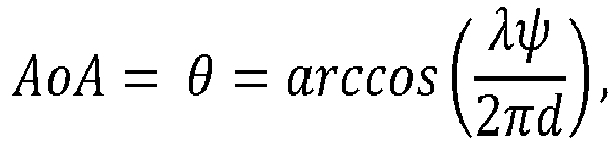
- λ = wavelength of the RF signal,
- ψ = the phase difference between the signals arrival at antennas A1 and A2, and
- d = distance between antennas A1 and A2.
- Using techniques known to those of skill in the art, a controller, such as
controller 240 ofreceiver circuit 200 offigure 1B , may calculate AoA. - For example, an embodiment of
receiver circuit 200 having one RF chain for each of antennas A1 and A2, assuming no carrier frequency offset, may calculate AoA as follows: - For transmitted signal

- fh = the carrier frequency,
- t 1 = the time of the transmitter oscillator
- fl = the baseband frequency,
- the signal received at antenna A1 is

ϕ 1 = the signal phase of the received sample; and - the signal received at antenna A2 is

ϕ 2 = the signal phase of the received sample. - The downconverted sample received at antenna A1 is:

t 2 = the time of the receiver oscillator. - The downconverted sample received at antenna A2 is:

- The phase difference is:


- Alternatively, an embodiment of
receiver circuit 200 having one RF chain for both antennas A1 and A2, assuming no carrier frequency offset, may calculate AoA as follows: - For transmitted signal

- fh = the carrier frequency,
- t 1 = the time of the transmitter oscillator
- fl = the baseband frequency,
- the signal received at antenna A1 is

ϕ 1 = the signal phase of the received sample; and - the signal received at antenna A2 is

- ϕ 2 = the signal phase of the received sample, and
- T = the sampling period.
- The downconverted sample received at antenna A1 is:

t 2 = the time of the receiver oscillator. - The downconverted sample received at antenna A2 is:

- The phase difference is:

- Therefore,

- Accordingly, the phase difference for calculating AoA (ϕ 2 - ϕ 1) is equal to the phase difference measured + 2πfl T

-
Figure 2B is a schematic diagram illustrating the geometry of phase-based estimation of angle of departure (AoD) of an RF signal transmitted by an antenna array comprising antenna A1 and antenna A2. - As shown, the RF signal is transmitted at an angle of departure (AoD) θ from antennas A1 and A2. According to geometric and trigonometric principles understood by those of skill in the art,

- λ = wavelength of the RF signal transmitted from antennas A1 and A2,
- ψ = the phase difference between the signals arrival at antenna RX, and
- d = distance between antennas A1 and A2.
- Using techniques known to those of skill in the art, a controller, such as
controller 240 ofreceiver circuit 200 offigure 1B , may calculate AoD. - For example, an embodiment of
receiver circuit 200 having one RF chain and a single antenna A1, assuming no carrier frequency offset, may calculate AoD as follows: - For signals respectively transmitted from antennas A1 and A2:

- fh = the carrier frequency,
- t 1 = the time of the transmitter oscillator
- fl = the baseband frequency,
- the first sample received at antenna RX is

ϕ 1 = the signal phase of the first sample; and - the second sample received at antenna RX is

- ϕ 2 = the signal phase of the second sample, and
- T = the sampling period.
- The downconverted first sample is:

t 2 = the time of the receiver oscillator. - The downconverted second sample is:

- The phase difference is:

- Therefore,

- Accordingly, the phase difference for calculating AoD (ϕ 2 - ϕ 1) is equal to the phase difference measured + 2πfl T.

-
Figure 3 is a graphic illustration of digitized samples of a received RF signal according to an example embodiment. The received RF signal may have been received by a receiver circuit, such asreceiver circuit 200 offigure 2 , having first and second receive antennas A1 and A2, and may be used to calculate AoA. Alternatively, the received RF signal may have been transmitted by a transmitter circuit, such astransmitter circuit 100 offigure 1 , having first and second transmit antennas A1 and A2, and may be used for calculating AoD. - The discussion will refer to antennas A1 and A2. It will be understood, based on the usage context, whether the referenced antennas A1 and A2 are transmit antennas or are receive antennas.
- The received RF signal is received by the receiver circuit, which generates digitized samples of the received RF signal using techniques discussed above and/or other techniques known to those of skill in the art.
- Because the received RF signal is time multiplexed either when transmitted with transmit antennas A1 and A2 or received with receive antennas A1 and A2, each sampling time T1-T6 has a single digitized sample. The receiver circuit generates a digitized sample y1 for the first sampling time T1 based on the received RF signal transmitted or received with antenna A1. The receiver circuit generates a digitized sample y2 for the second sampling time T2 based on the received RF signal transmitted or received with antenna A2. The receiver circuit generates a digitized sample y3 for the third sampling time T3 based on the received RF signal transmitted or received with antenna A1. The receiver circuit generates a digitized sample y4 for the fourth sampling time T4 based on the received RF signal transmitted or received with antenna A2. The receiver circuit generates a digitized sample y5 for the fifth sampling time T5 based on the received RF signal transmitted or received with antenna A1. The receiver circuit generates a digitized sample y6 for the sixth sampling time T6 based on the received RF signal transmitted or received with antenna A2.
- As understood by those of skill in the art, sampling times may be spaced apart by a switching time, during which, for example, either the transmitter circuit disconnects an amplifier from one of transmit antennas A1 and A2 and connects the amplifier to the other of transmit antennas A1 and A2, or the receiver circuit disconnects an amplifier from one of receive antennas A1 and A2 and connects the amplifier to the other of receive antennas A1 and A2.
- The digital samples generated by the receiver circuit may be used to calculate AoA or AoD. However, because calculations of AoA or AoD are preferably made with digitized samples for the same sampling time, additional digital samples may be calculated based on the digitized samples generated by the RF chain of the receiver circuit.
-
Figure 4 is a graphic illustration of received and calculated samples which may be used for calculating AoA or AoD. Samples y1 of sampling time T1, y3 of sampling time T3, and y5 of sampling time T5, are generated by the receiver circuit by digitizing the received RF signal of transmit or receive antenna A1 using techniques discussed elsewhere herein, or using other techniques understood by those of skill in the art. Similarly, samples y2 of sampling time T2, y4 of sampling time T4, and y6 of sampling time T6 are generated by the receiver circuit by digitizing the received RF signal of transmit or receive antenna A2 using techniques discussed elsewhere herein, or using other techniques understood by those of skill in the art. In addition, samples ylc2 of sampling time T1, y2c1 of sampling time T2, y3c2 of sampling time T3, y4c1 of sampling time T4, y5c2 of sampling time T5, and y6c1 of sampling time T6 are calculated by the receiver circuit based on digitized samples of the received RF signal using techniques discussed elsewhere herein, or using other techniques understood by those of skill in the art. - In some embodiments, samples ylc2 of sampling time T1, y3c2 of sampling time T3, and y5c2 of sampling time T5 are calculated based on digitized samples of the received RF signal transmitted or received by antenna A2. For example, samples ylc2 of sampling time T1, y3c2 of sampling time T3, and y5c2 of sampling time T5 may be calculated based at least in part on digitized sample y2 of sampling time T2, digitized sample y4 of sampling time T4, and digitized sample y6 of sampling time T6.
- For example, a first digital input signal including digitized sample y2 of sampling time T2, digitized sample y4 of sampling time T4, and digitized sample y6 of sampling time T6 may be input to a digital filter, such as a first digital FIR filter. Any suitable digital FIR filter may be used.
- As understood by those of skill in the art, as part of the filtering process, the first digital FIR filter may oversample the first digital signal input thereto, and may, consequently, generate digital samples corresponding with times between the sampling times of the digitized samples of the first digital input signal.
- For example, the first digital input signal including digitized sample y2 of sampling time T2, digitized sample y4 of sampling time T4, and digitized sample y6 of sampling time T6 may be input to the first digital FIR oversampling by a factor of 2. Based at least in part on digitized sample y2, digitized sample y4, and digitized sample y6 of the first digital input signal, the first digital FIR filter may calculate samples ylc2 of sampling time T1, y3c2 of sampling time T3, and y5c2 of sampling time T5, as illustrated in
figure 4 . - In some embodiments, y2c1 of sampling time T2, y4c1 of sampling time T4, and y6c1 of sampling time T6 are calculated based on digitized samples of the received RF signal transmitted or received by antenna A1. For example, samples y2c1 of sampling time T2, y4c1 of sampling time T4, and y6c1 of sampling time T6 may be calculated based on digitized sample y1 of sampling time T1, digitized sample y3 of sampling time T3, and digitized sample y5 of sampling time T5.
- For example, a second digital input signal including digitized sample y1 of sampling time T1, digitized sample y3 of sampling time T3, and digitized sample y5 of sampling time T5 may be input to a digital filter, such as a second digital FIR filter. Any suitable digital FIR filter may be used.
- As understood by those of skill in the art, as part of the filtering process, the second digital FIR filter may oversample the digital signal input thereto, and may, consequently, generate digital samples corresponding with times between the sampling times of the digitized samples of the second digital input signal.
- For example, the second digital input signal including digitized sample y1 of sampling time T1, digitized sample y3 of sampling time T3, and digitized sample y5 of sampling time T5 may be input to the second digital FIR oversampling by a factor of 2. Based at least in part on digitized sample y1, digitized sample y3, and digitized sample y5 of the second digital input signal, the digital FIR filter may calculate samples y2c1 of sampling time T2, y4c1 of sampling time T4, and y6c1 of sampling time T6, as illustrated in
figure 4 . - Using techniques discussed herein, and/or other techniques known to those of skill in the art, the receiver circuit may calculate a measured AoA or AoD based on the digitized and calculated samples illustrated in
figure 4 . - For example, a measured AoA or AoD may be calculated based on the digitized and calculated samples of multiple sampling times according to, for example, a Multiple Signal Classification (MUSIC) AoA or AoD algorithm, as understood by those of skill in the art.
- Alternatively, an estimate of AoA or AoD may be calculated for each sampling time. For example, each of sample pairs y1 and ylc2, y2c1 and y2, y3 and y3c2, y4c1 and y4, y5 and y5c2, and y6c1 and y6 may be used to calculate an estimate of AoA or AoD. In addition, the calculated estimates of AoA or AoD may be used to calculate a measured AoA or AoD using any of the techniques described herein and/or any other techniques known to those of skill in the art. For example, the measured AoA or AoD may be calculated as an average of the estimates of AoA or AoD.
-
Figure 5 is a graphic illustration of digitized samples of a received RF signal according to an example embodiment. The received RF signal may have been received by a receiver circuit, such asreceiver circuit 200 offigure 2 , having receive antennas A1-AN, and may be used to calculate AoA. Alternatively, the received RF signal may have been transmitted by a transmitter circuit, such astransmitter circuit 100 offigure 1 , having antennas A1-AN, and may be used for calculating AoD. - The discussion will refer to antennas A1-AN. It will be understood, based on the usage context, whether the referenced antennas A1-AN are transmit antennas or are receive antennas.
- The received RF signal is received by the receiver circuit, which generates digitized samples of the received RF signal using techniques discussed above and/or other techniques known to those of skill in the art.
- Because the received RF signal is time multiplexed either when transmitted with transmit antennas A1-AN or received with receive antennas A1-AN, each sampling time T1-TN has a single digitized sample. The receiver circuit generates a digitized sample y1 for the first sampling time T1 based on the received RF signal transmitted or received with antenna A1. The receiver circuit generates a digitized sample yN for the Nth sampling time TN based on the received RF signal transmitted or received with antenna AN. The receiver circuit generates another digitized sample yx for each of the other sampling times Tx between T1 and TN based on the received RF signal transmitted or received with an antenna Ax. As understood by those of skill in the art, the receiver circuit continues to generate samples based on the received RF signal with a repeating pattern of the sample generation scheme illustrated in
figure 5 . - As understood by those of skill in the art, sampling times may be spaced apart by a switching time, during which, for example, either the transmitter circuit disconnects an amplifier from one of the transmit antennas A1-AN and connects the amplifier to a next transmit antenna, or the receiver circuit disconnects an amplifier from one of receive antennas A1-AN and connects the amplifier to a next receive antennas.
- The digital samples generated by the receiver circuit may be used to calculate AoA or AoD. However, because calculations of AoA or AoD are preferably made with digitized samples for the same sampling time, additional digital samples may be calculated based on the digitized samples generated by the RF chain of the receiver circuit.
-
Figure 6 is a graphic illustration of received and calculated samples which may be used for calculating AoA or AoD. The receiver circuit generates a digitized sample y1 for the first sampling time T1 based on the received RF signal transmitted or received with antenna A1. The receiver circuit generates a digitized sample y2 for the second sampling time T2 based on the received RF signal transmitted or received with antenna A2. The receiver circuit also generates a digitized sample yN-1 for the N-1th sampling time TN-1 based on the received RF signal transmitted or received with antenna AN-1. The receiver circuit also generates a digitized sample yN for the Nth sampling time TN based on the received RF signal transmitted or received with antenna AN. The receiver circuit generates another digitized sample yx for each of the other sampling times Tx between sampling times T2 and TN-1 based on the received RF signal transmitted or received with an antenna Ax between antennas A2 and AN-1. As understood by those of skill in the art, the receiver circuit continues to generate samples based on the received RF signal with a repeating pattern of the sample generation scheme illustrated infigure 6 . - In addition, samples ylc2-ylcN of sampling time T1, y2c1, y2cN-1, and y2cN of sampling time T2, yN-1c1, yN-1c2, and yN to 1cN of sampling time TN-1, yNc1 to yNcN-1 of sampling time TN, and other samples corresponding with the antennas and sampling times not identified in
figure 6 are calculated by the receiver circuit based on digitized samples of the received RF signal using techniques discussed elsewhere herein, or using other techniques understood by those of skill in the art. - In some embodiments, the samples corresponding with each particular antenna are calculated based on digitized samples calculated based on the RF signal transmitted or received by the particular antenna. For example, the samples corresponding with antenna Ax are calculated based on digitized samples calculated based on the RF signal transmitted or received by antenna Ax.
- For example, a first digital input signal including digitized sample y1 of sampling time T1 and other digitized samples (not shown) calculated based on the RF signal transmitted or received by antenna A1, for example, of sampling times TN+1, T2N+1, etc. (not shown) may be input to a digital filter, such as a first digital FIR filter. Any suitable digital FIR filter may be used.
- As understood by those of skill in the art, as part of the filtering process, the first digital FIR filter may oversample the first digital signal input thereto, and may, consequently, generate digital samples corresponding with times between the sampling times of the digitized samples of the first digital input signal.
- For example, the first digital input signal including digitized sample y1 of sampling time T1 and the other digitized samples may be input to the first digital FIR oversampling by a factor of N. Based on the first digital input signal, the first digital FIR filter may calculate samples y2c1 - yNc1 of sampling times T2-TN, as illustrated in
figure 6 . - In addition, an xth digital input signal including digitized sample yx of sampling time Tx, and other digitized samples (not shown) calculated based on the RF signal transmitted or received by antenna Ax, for example, of sampling times TN+x, T2N+x, etc. (not shown) may be input to a digital filter, such as a first digital FIR filter. Any suitable digital FIR filter may be used.
- As understood by those of skill in the art, as part of the filtering process, the xth digital FIR filter may oversample the digital signal input thereto, and may, consequently, generate digital samples corresponding with times between the sampling times of the digitized samples of the xth digital input signal.
- For example, the xth digital input signal including digitized sample yx of sampling time Tx and the other digitized samples may be input to the xth digital FIR oversampling by a factor of N. Based on the xth digital input signal, the xth digital FIR filter may calculate samples for sampling times T1 to Tx-1 and Tx+1 to TN, as illustrated in
figure 6 . - Accordingly, N digital filters may be used to calculate samples to be used with the digitized samples of
figure 5 . - Using techniques discussed herein, and/or other techniques known to those of skill in the art, the receiver circuit may calculate a measured AoA or AoD based on the digitized and calculated samples illustrated in
figure 6 . - For example, a measured AoA or AoD may be calculated based on the digitized and calculated samples according to a Multiple Signal Classification (MUSIC) AoA or AoD algorithm, as understood by those of skill in the art.
- Alternatively, an estimate of AoA or AoD may be calculated for each sampling time. In addition, the calculated estimates of AoA or AoD may be used to calculate a measured AoA or AoD using any of the techniques described herein and/or any other techniques known to those of skill in the art. For example, the measured AoA or AoD may be calculated as an average of the estimates of AoA or AoD.
- In the descriptions above and in the claims, phrases such as "at least one of' or "one or more of' may occur followed by a conjunctive list of elements or features. The term "and/or" may also occur in a list of two or more elements or features. Unless otherwise implicitly or explicitly contradicted by the context in which it used, such a phrase is intended to mean any of the listed elements or features individually or any of the recited elements or features in combination with any of the other recited elements or features. For example, the phrases "at least one of A and B;" "one or more of A and B;" and "A and/or B" are each intended to mean "A alone, B alone, or A and B together." A similar interpretation is also intended for lists including three or more items. For example, the phrases "at least one of A, B, and C;" "one or more of A, B, and C;" and "A, B, and/or C" are each intended to mean "A alone, B alone, C alone, A and B together, A and C together, B and C together, or A and B and C together." Use of the term "based on," above and in the claims is intended to mean, "based at least in part on," such that an unrecited feature or element is also permissible.
- The subject matter described herein can be embodied in systems, apparatus, methods, and/or articles depending on the desired configuration. The implementations set forth in the foregoing description do not represent all implementations consistent with the subject matter described herein. Instead, they are merely some examples consistent with aspects related to the described subject matter. Although a few variations have been described in detail above, other modifications or additions are possible. In particular, further features and/or variations can be provided in addition to those set forth herein. For example, the implementations described above can be directed to various combinations and subcombinations of the disclosed features and/or combinations and subcombinations of several further features disclosed above. In addition, the logic flows depicted in the accompanying figures and/or described herein do not necessarily require the particular order shown, or sequential order, to achieve desirable results. Other implementations may be within the scope of the following claims.
Claims (15)
- A receiver circuit, comprising:one or more receiver antennas configured to receive a plurality of RF signals transmitted from a transmitter circuit comprising one or more transmit antennas;an RF chain configured to generate a plurality of digitized samples of the received RF signals; anda controller configured to receive the digitized samples, to calculate a plurality of additional samples, and to calculate a measured angle of arrival or angle of departure (AoA or AoD) of the RF signals based on the digitized samples and the calculated additional samples.
- The receiver circuit of claim 1, wherein the RF signals are either transmitted by first and second transmit antennas of the transmitter circuit or are received by first and second receive antennas of the receiver circuit.
- The receiver circuit of claim 2, wherein a first set of digitized samples are samples of the RF signals either transmitted by the first transmit antenna of the transmitter circuit or received by the first receive antenna of the receiver circuit, and wherein a second set of digitized samples are samples of the RF signals either transmitted by the second transmit antenna of the transmitter circuit or received by the second receive antenna of the receiver circuit.
- The receiver circuit of claim 3, wherein a first set of additional samples is calculated based on the first set of digitized samples, and wherein a second set of additional samples is calculated based on the second set of digitized samples.
- The receiver circuit of claim 3, wherein the first set of digitized samples are samples of the RF signals taken at a plurality of first sample times, wherein the second set of digitized samples are samples of the RF signals taken at a plurality of second sample times, and wherein each of the first sample times is different from each of the second sample times.
- The receiver circuit of claim 5, wherein each of the additional samples of the first set of additional samples corresponds with one of the second sample times, and wherein each of the additional samples of the second set of additional samples corresponds with one of the first sample times; and
wherein the controller is configured to calculate the measured AoA or AoD based on the digitized samples and the calculated additional samples corresponding with the plurality of first sample times and corresponding with the plurality of second sample times. - The receiver circuit of claim 1, wherein the RF signals are transmitted by a single transmit antenna of the transmitter circuit and are received by a plurality of receive antennas of the receiver circuit; or
wherein the RF signals are transmitted by a plurality of transmit antennas of the transmitter circuit and are received by a single receive antenna of the receiver circuit. - The receiver circuit of claim 1, wherein the RF chain is selectably connectable to each of a plurality of receive antennas.
- A method of using a receiver circuit, the method comprising:with one or more receiver antennas, receiving a plurality of RF signals transmitted from a transmitter circuit comprising one or more transmit antennas;with an RF chain, generating a plurality of digitized samples of the received RF signals;with a controller, receiving the digitized samples;with the controller, calculating a plurality of additional samples; andwith the controller, calculating a measured angle of arrival or angle of departure (AoA or AoD) of the RF signals based on the digitized samples and the calculated additional samples.
- The method of claim 9, wherein the RF signals are either transmitted by first and second transmit antennas of the transmitter circuit or are received by first and second receive antennas of the receiver circuit; and
wherein a first set of digitized samples are samples of the RF signals either transmitted by the first transmit antenna of the transmitter circuit or received by the first receive antenna of the receiver circuit, and wherein a second set of digitized samples are samples of the RF signals either transmitted by the second transmit antenna of the transmitter circuit or received by the second receive antenna of the receiver circuit. - The method of claim 10, wherein a first set of additional samples is calculated based on the first set of digitized samples, and wherein a second set of additional samples is calculated based on the second set of digitized samples.
- The method of claim 10, wherein the first set of digitized samples are samples of the RF signals taken at a plurality of first sample times, wherein the second set of digitized samples are samples of the RF signals taken at a plurality of second sample times, and wherein each of the first sample times is different from each of the second sample times.
- The method of claim 12, wherein each of the additional samples of the first set of additional samples corresponds with one of the second sample times, and wherein each of the additional samples of the second set of additional samples corresponds with one of the first sample times; and
wherein with the controller, calculating the measured AoA or AoD based on the digitized samples and the calculated additional samples corresponding with the plurality of first sample times and corresponding with the plurality of second sample times. - The method of claim 9, wherein the RF signals are transmitted by a single transmit antenna of the transmitter circuit and are received by a plurality of receive antennas of the receiver circuit; or
wherein the RF signals are transmitted by a plurality of transmit antennas of the transmitter circuit and are received by a single receive antenna of the receiver circuit. - The method of claim 9, further comprising, selectably connecting the RF chain to each of a plurality of receive antennas.
Applications Claiming Priority (1)
| Application Number | Priority Date | Filing Date | Title |
|---|---|---|---|
| US17/006,834 US11619699B2 (en) | 2020-08-30 | 2020-08-30 | AoA/AoD calculation in the presence of carrier frequency offset |
Publications (3)
| Publication Number | Publication Date |
|---|---|
| EP3961240A2 true EP3961240A2 (en) | 2022-03-02 |
| EP3961240A3 EP3961240A3 (en) | 2022-03-30 |
| EP3961240B1 EP3961240B1 (en) | 2024-10-16 |
Family
ID=77518936
Family Applications (1)
| Application Number | Title | Priority Date | Filing Date |
|---|---|---|---|
| EP21193084.7A Active EP3961240B1 (en) | 2020-08-30 | 2021-08-25 | Aoa/aod calculation in the presence of carrier frequency offset |
Country Status (3)
| Country | Link |
|---|---|
| US (1) | US11619699B2 (en) |
| EP (1) | EP3961240B1 (en) |
| CN (1) | CN113612491B (en) |
Families Citing this family (1)
| Publication number | Priority date | Publication date | Assignee | Title |
|---|---|---|---|---|
| TWI907946B (en) * | 2024-02-02 | 2025-12-11 | 廣達電腦股份有限公司 | System and method for detecting people entering and leaving field |
Family Cites Families (13)
| Publication number | Priority date | Publication date | Assignee | Title |
|---|---|---|---|---|
| US6489923B1 (en) | 1999-09-16 | 2002-12-03 | Nortel Networks Limited | Position location method and apparatus for a mobile telecommunications system |
| US9054856B2 (en) | 2011-02-07 | 2015-06-09 | Nokia Technologies Oy | Processing samples of a received RF signal |
| WO2013020122A2 (en) | 2011-08-03 | 2013-02-07 | Felix Markhovsky | Multi-path mitigation in rangefinding and tracking objects using reduced attenuation rf technology |
| GB2539735A (en) | 2015-06-25 | 2016-12-28 | Airspan Networks Inc | Sub-sampling antenna elements |
| US9860096B1 (en) | 2015-08-25 | 2018-01-02 | Marvell International Ltd. | Systems and methods for carrier frequency offset and drift cancellation based indoor position estimation |
| US10330783B1 (en) | 2016-09-19 | 2019-06-25 | Marvell International Ltd. | Location service offload for bluetooth positioning |
| CN110333478B (en) | 2018-03-30 | 2022-05-17 | 华为技术有限公司 | A kind of arrival angle, departure angle determination method and communication device |
| CN109085563B (en) | 2018-06-26 | 2022-06-21 | 重庆邮电大学 | WLAN ranging method based on software radio platform |
| US10594517B1 (en) * | 2018-10-26 | 2020-03-17 | Wistron Neweb Corporation | Channel estimation system and method thereof |
| EP3660532B1 (en) | 2018-11-27 | 2022-09-14 | Safectory GmbH | Method, device and system for determining the angle of arrival (aoa) for locating an object |
| US10972886B2 (en) * | 2018-12-04 | 2021-04-06 | Cypress Semiconductor Corporation | Dynamic antenna array pattern switching in wireless systems |
| US11228469B1 (en) * | 2020-07-16 | 2022-01-18 | Deeyook Location Technologies Ltd. | Apparatus, system and method for providing locationing multipath mitigation |
| US11483052B2 (en) * | 2020-08-30 | 2022-10-25 | Shenzhen GOODIX Technology Co., Ltd. | AoA/AoD calculations in multipath fading environments |
-
2020
- 2020-08-30 US US17/006,834 patent/US11619699B2/en active Active
-
2021
- 2021-08-24 CN CN202110977351.8A patent/CN113612491B/en active Active
- 2021-08-25 EP EP21193084.7A patent/EP3961240B1/en active Active
Also Published As
| Publication number | Publication date |
|---|---|
| EP3961240B1 (en) | 2024-10-16 |
| US11619699B2 (en) | 2023-04-04 |
| EP3961240A3 (en) | 2022-03-30 |
| CN113612491B (en) | 2023-03-28 |
| CN113612491A (en) | 2021-11-05 |
| US20220065974A1 (en) | 2022-03-03 |
Similar Documents
| Publication | Publication Date | Title |
|---|---|---|
| US10955542B2 (en) | Radar apparatus and direction-of-arrival estimation device | |
| US10613195B2 (en) | Radar apparatus and radar method | |
| US7612715B2 (en) | Direction finding | |
| JP6148622B2 (en) | Radar equipment | |
| WO2017187299A2 (en) | Successive signal interference mitigation | |
| US10187134B1 (en) | Tx beamformer in MIMO radar | |
| EP2972468B1 (en) | System and method for calibration and built-in self test of automobile radar system | |
| EP3961240B1 (en) | Aoa/aod calculation in the presence of carrier frequency offset | |
| US20230095335A1 (en) | Phase based distance estimation with carrier frequency offset | |
| EP4053592B1 (en) | Method and system for single target direction of arrival estimation for sparse array radar systems | |
| EP3974859A2 (en) | Aoa/aod calculation with low angle of incidence | |
| US11483052B2 (en) | AoA/AoD calculations in multipath fading environments | |
| US11656314B2 (en) | AoA/AoD calculation with mirror disambiguation | |
| US5568394A (en) | Interferometry with multipath nulling | |
| US12607732B2 (en) | Systems and methods for detecting physical objects using passive radar receivers | |
| WO2007083889A1 (en) | Method and apparatus for transmitter locating using a single receiver | |
| RU2268479C1 (en) | Mode of detection of radio contrasting objects and measuring of the speed and the acceleration of approaching to them of a flying vehicle | |
| EP4160258B1 (en) | Transceiver circuit | |
| CN121356635B (en) | Communication perception integrated equipment with super resolution and calibration method | |
| JP2001264403A (en) | Radio wave arrival direction detector | |
| Saito et al. | Robust source number estimation based on FMCW radar with multiple initial frequencies | |
| RU2423798C1 (en) | Clock synchronisation device | |
| SU1539699A1 (en) | Method of measuring phase sequence of radio pulses in carrier frequency | |
| JPS62156586A (en) | Radar device | |
| SU1575255A1 (en) | Method of determining directions of arrival of n plane waves and device for effecting same |
Legal Events
| Date | Code | Title | Description |
|---|---|---|---|
| PUAI | Public reference made under article 153(3) epc to a published international application that has entered the european phase |
Free format text: ORIGINAL CODE: 0009012 |
|
| STAA | Information on the status of an ep patent application or granted ep patent |
Free format text: STATUS: REQUEST FOR EXAMINATION WAS MADE |
|
| PUAL | Search report despatched |
Free format text: ORIGINAL CODE: 0009013 |
|
| 17P | Request for examination filed |
Effective date: 20210825 |
|
| AK | Designated contracting states |
Kind code of ref document: A2 Designated state(s): AL AT BE BG CH CY CZ DE DK EE ES FI FR GB GR HR HU IE IS IT LI LT LU LV MC MK MT NL NO PL PT RO RS SE SI SK SM TR |
|
| AK | Designated contracting states |
Kind code of ref document: A3 Designated state(s): AL AT BE BG CH CY CZ DE DK EE ES FI FR GB GR HR HU IE IS IT LI LT LU LV MC MK MT NL NO PL PT RO RS SE SI SK SM TR |
|
| RIC1 | Information provided on ipc code assigned before grant |
Ipc: G01S 3/48 20060101ALN20220220BHEP Ipc: G01S 3/20 20060101ALI20220220BHEP Ipc: G01S 3/46 20060101ALI20220220BHEP Ipc: G01S 3/04 20060101ALI20220220BHEP Ipc: G01S 1/08 20060101ALI20220220BHEP Ipc: G01S 1/04 20060101AFI20220220BHEP |
|
| STAA | Information on the status of an ep patent application or granted ep patent |
Free format text: STATUS: EXAMINATION IS IN PROGRESS |
|
| 17Q | First examination report despatched |
Effective date: 20221219 |
|
| GRAP | Despatch of communication of intention to grant a patent |
Free format text: ORIGINAL CODE: EPIDOSNIGR1 |
|
| STAA | Information on the status of an ep patent application or granted ep patent |
Free format text: STATUS: GRANT OF PATENT IS INTENDED |
|
| RIC1 | Information provided on ipc code assigned before grant |
Ipc: G01S 3/48 20060101ALN20240625BHEP Ipc: G01S 3/20 20060101ALI20240625BHEP Ipc: G01S 3/46 20060101ALI20240625BHEP Ipc: G01S 3/04 20060101ALI20240625BHEP Ipc: G01S 1/08 20060101ALI20240625BHEP Ipc: G01S 1/04 20060101AFI20240625BHEP |
|
| INTG | Intention to grant announced |
Effective date: 20240715 |
|
| GRAS | Grant fee paid |
Free format text: ORIGINAL CODE: EPIDOSNIGR3 |
|
| GRAA | (expected) grant |
Free format text: ORIGINAL CODE: 0009210 |
|
| STAA | Information on the status of an ep patent application or granted ep patent |
Free format text: STATUS: THE PATENT HAS BEEN GRANTED |
|
| AK | Designated contracting states |
Kind code of ref document: B1 Designated state(s): AL AT BE BG CH CY CZ DE DK EE ES FI FR GB GR HR HU IE IS IT LI LT LU LV MC MK MT NL NO PL PT RO RS SE SI SK SM TR |
|
| REG | Reference to a national code |
Ref country code: GB Ref legal event code: FG4D |
|
| REG | Reference to a national code |
Ref country code: CH Ref legal event code: EP |
|
| REG | Reference to a national code |
Ref country code: IE Ref legal event code: FG4D |
|
| REG | Reference to a national code |
Ref country code: DE Ref legal event code: R096 Ref document number: 602021020267 Country of ref document: DE |
|
| REG | Reference to a national code |
Ref country code: LT Ref legal event code: MG9D |
|
| REG | Reference to a national code |
Ref country code: NL Ref legal event code: MP Effective date: 20241016 |
|
| REG | Reference to a national code |
Ref country code: AT Ref legal event code: MK05 Ref document number: 1733332 Country of ref document: AT Kind code of ref document: T Effective date: 20241016 |
|
| PG25 | Lapsed in a contracting state [announced via postgrant information from national office to epo] |
Ref country code: NL Free format text: LAPSE BECAUSE OF FAILURE TO SUBMIT A TRANSLATION OF THE DESCRIPTION OR TO PAY THE FEE WITHIN THE PRESCRIBED TIME-LIMIT Effective date: 20241016 |
|
| PG25 | Lapsed in a contracting state [announced via postgrant information from national office to epo] |
Ref country code: NL Free format text: LAPSE BECAUSE OF FAILURE TO SUBMIT A TRANSLATION OF THE DESCRIPTION OR TO PAY THE FEE WITHIN THE PRESCRIBED TIME-LIMIT Effective date: 20241016 |
|
| PG25 | Lapsed in a contracting state [announced via postgrant information from national office to epo] |
Ref country code: IS Free format text: LAPSE BECAUSE OF FAILURE TO SUBMIT A TRANSLATION OF THE DESCRIPTION OR TO PAY THE FEE WITHIN THE PRESCRIBED TIME-LIMIT Effective date: 20250216 Ref country code: PT Free format text: LAPSE BECAUSE OF FAILURE TO SUBMIT A TRANSLATION OF THE DESCRIPTION OR TO PAY THE FEE WITHIN THE PRESCRIBED TIME-LIMIT Effective date: 20250217 Ref country code: HR Free format text: LAPSE BECAUSE OF FAILURE TO SUBMIT A TRANSLATION OF THE DESCRIPTION OR TO PAY THE FEE WITHIN THE PRESCRIBED TIME-LIMIT Effective date: 20241016 |
|
| PG25 | Lapsed in a contracting state [announced via postgrant information from national office to epo] |
Ref country code: FI Free format text: LAPSE BECAUSE OF FAILURE TO SUBMIT A TRANSLATION OF THE DESCRIPTION OR TO PAY THE FEE WITHIN THE PRESCRIBED TIME-LIMIT Effective date: 20241016 |
|
| PG25 | Lapsed in a contracting state [announced via postgrant information from national office to epo] |
Ref country code: BG Free format text: LAPSE BECAUSE OF FAILURE TO SUBMIT A TRANSLATION OF THE DESCRIPTION OR TO PAY THE FEE WITHIN THE PRESCRIBED TIME-LIMIT Effective date: 20241016 |
|
| PG25 | Lapsed in a contracting state [announced via postgrant information from national office to epo] |
Ref country code: ES Free format text: LAPSE BECAUSE OF FAILURE TO SUBMIT A TRANSLATION OF THE DESCRIPTION OR TO PAY THE FEE WITHIN THE PRESCRIBED TIME-LIMIT Effective date: 20241016 |
|
| PG25 | Lapsed in a contracting state [announced via postgrant information from national office to epo] |
Ref country code: NO Free format text: LAPSE BECAUSE OF FAILURE TO SUBMIT A TRANSLATION OF THE DESCRIPTION OR TO PAY THE FEE WITHIN THE PRESCRIBED TIME-LIMIT Effective date: 20250116 |
|
| PG25 | Lapsed in a contracting state [announced via postgrant information from national office to epo] |
Ref country code: LV Free format text: LAPSE BECAUSE OF FAILURE TO SUBMIT A TRANSLATION OF THE DESCRIPTION OR TO PAY THE FEE WITHIN THE PRESCRIBED TIME-LIMIT Effective date: 20241016 Ref country code: AT Free format text: LAPSE BECAUSE OF FAILURE TO SUBMIT A TRANSLATION OF THE DESCRIPTION OR TO PAY THE FEE WITHIN THE PRESCRIBED TIME-LIMIT Effective date: 20241016 Ref country code: GR Free format text: LAPSE BECAUSE OF FAILURE TO SUBMIT A TRANSLATION OF THE DESCRIPTION OR TO PAY THE FEE WITHIN THE PRESCRIBED TIME-LIMIT Effective date: 20250117 |
|
| PG25 | Lapsed in a contracting state [announced via postgrant information from national office to epo] |
Ref country code: PL Free format text: LAPSE BECAUSE OF FAILURE TO SUBMIT A TRANSLATION OF THE DESCRIPTION OR TO PAY THE FEE WITHIN THE PRESCRIBED TIME-LIMIT Effective date: 20241016 |
|
| PG25 | Lapsed in a contracting state [announced via postgrant information from national office to epo] |
Ref country code: RS Free format text: LAPSE BECAUSE OF FAILURE TO SUBMIT A TRANSLATION OF THE DESCRIPTION OR TO PAY THE FEE WITHIN THE PRESCRIBED TIME-LIMIT Effective date: 20250116 |
|
| PG25 | Lapsed in a contracting state [announced via postgrant information from national office to epo] |
Ref country code: SM Free format text: LAPSE BECAUSE OF FAILURE TO SUBMIT A TRANSLATION OF THE DESCRIPTION OR TO PAY THE FEE WITHIN THE PRESCRIBED TIME-LIMIT Effective date: 20241016 |
|
| PG25 | Lapsed in a contracting state [announced via postgrant information from national office to epo] |
Ref country code: DK Free format text: LAPSE BECAUSE OF FAILURE TO SUBMIT A TRANSLATION OF THE DESCRIPTION OR TO PAY THE FEE WITHIN THE PRESCRIBED TIME-LIMIT Effective date: 20241016 |
|
| REG | Reference to a national code |
Ref country code: DE Ref legal event code: R097 Ref document number: 602021020267 Country of ref document: DE |
|
| PG25 | Lapsed in a contracting state [announced via postgrant information from national office to epo] |
Ref country code: EE Free format text: LAPSE BECAUSE OF FAILURE TO SUBMIT A TRANSLATION OF THE DESCRIPTION OR TO PAY THE FEE WITHIN THE PRESCRIBED TIME-LIMIT Effective date: 20241016 |
|
| PG25 | Lapsed in a contracting state [announced via postgrant information from national office to epo] |
Ref country code: RO Free format text: LAPSE BECAUSE OF FAILURE TO SUBMIT A TRANSLATION OF THE DESCRIPTION OR TO PAY THE FEE WITHIN THE PRESCRIBED TIME-LIMIT Effective date: 20241016 |
|
| PG25 | Lapsed in a contracting state [announced via postgrant information from national office to epo] |
Ref country code: SK Free format text: LAPSE BECAUSE OF FAILURE TO SUBMIT A TRANSLATION OF THE DESCRIPTION OR TO PAY THE FEE WITHIN THE PRESCRIBED TIME-LIMIT Effective date: 20241016 |
|
| PG25 | Lapsed in a contracting state [announced via postgrant information from national office to epo] |
Ref country code: CZ Free format text: LAPSE BECAUSE OF FAILURE TO SUBMIT A TRANSLATION OF THE DESCRIPTION OR TO PAY THE FEE WITHIN THE PRESCRIBED TIME-LIMIT Effective date: 20241016 |
|
| PG25 | Lapsed in a contracting state [announced via postgrant information from national office to epo] |
Ref country code: IT Free format text: LAPSE BECAUSE OF FAILURE TO SUBMIT A TRANSLATION OF THE DESCRIPTION OR TO PAY THE FEE WITHIN THE PRESCRIBED TIME-LIMIT Effective date: 20241016 |
|
| PLBE | No opposition filed within time limit |
Free format text: ORIGINAL CODE: 0009261 |
|
| STAA | Information on the status of an ep patent application or granted ep patent |
Free format text: STATUS: NO OPPOSITION FILED WITHIN TIME LIMIT |
|
| PG25 | Lapsed in a contracting state [announced via postgrant information from national office to epo] |
Ref country code: SE Free format text: LAPSE BECAUSE OF FAILURE TO SUBMIT A TRANSLATION OF THE DESCRIPTION OR TO PAY THE FEE WITHIN THE PRESCRIBED TIME-LIMIT Effective date: 20241016 |
|
| 26N | No opposition filed |
Effective date: 20250717 |
|
| REG | Reference to a national code |
Ref country code: DE Ref legal event code: R119 Ref document number: 602021020267 Country of ref document: DE |
|
| REG | Reference to a national code |
Ref country code: CH Ref legal event code: H13 Free format text: ST27 STATUS EVENT CODE: U-0-0-H10-H13 (AS PROVIDED BY THE NATIONAL OFFICE) Effective date: 20260324 |
|
| PG25 | Lapsed in a contracting state [announced via postgrant information from national office to epo] |
Ref country code: MC Free format text: LAPSE BECAUSE OF FAILURE TO SUBMIT A TRANSLATION OF THE DESCRIPTION OR TO PAY THE FEE WITHIN THE PRESCRIBED TIME-LIMIT Effective date: 20241016 |
|
| PG25 | Lapsed in a contracting state [announced via postgrant information from national office to epo] |
Ref country code: LU Free format text: LAPSE BECAUSE OF NON-PAYMENT OF DUE FEES Effective date: 20250825 |
|
| PG25 | Lapsed in a contracting state [announced via postgrant information from national office to epo] |
Ref country code: CH Free format text: LAPSE BECAUSE OF NON-PAYMENT OF DUE FEES Effective date: 20250831 |
|
| GBPC | Gb: european patent ceased through non-payment of renewal fee |
Effective date: 20250825 |