EP3961226A1 - Flow path device, cartridge, and measurement system - Google Patents
Flow path device, cartridge, and measurement system Download PDFInfo
- Publication number
- EP3961226A1 EP3961226A1 EP20795032.0A EP20795032A EP3961226A1 EP 3961226 A1 EP3961226 A1 EP 3961226A1 EP 20795032 A EP20795032 A EP 20795032A EP 3961226 A1 EP3961226 A1 EP 3961226A1
- Authority
- EP
- European Patent Office
- Prior art keywords
- storage chamber
- flow path
- specimen
- chamber
- syringe
- Prior art date
- Legal status (The legal status is an assumption and is not a legal conclusion. Google has not performed a legal analysis and makes no representation as to the accuracy of the status listed.)
- Withdrawn
Links
Images






Classifications
-
- B—PERFORMING OPERATIONS; TRANSPORTING
- B01—PHYSICAL OR CHEMICAL PROCESSES OR APPARATUS IN GENERAL
- B01L—CHEMICAL OR PHYSICAL LABORATORY APPARATUS FOR GENERAL USE
- B01L3/00—Containers or dishes for laboratory use, e.g. laboratory glassware; Droppers
- B01L3/50—Containers for the purpose of retaining a material to be analysed, e.g. test tubes
- B01L3/502—Containers for the purpose of retaining a material to be analysed, e.g. test tubes with fluid transport, e.g. in multi-compartment structures
-
- B—PERFORMING OPERATIONS; TRANSPORTING
- B01—PHYSICAL OR CHEMICAL PROCESSES OR APPARATUS IN GENERAL
- B01L—CHEMICAL OR PHYSICAL LABORATORY APPARATUS FOR GENERAL USE
- B01L3/00—Containers or dishes for laboratory use, e.g. laboratory glassware; Droppers
- B01L3/50—Containers for the purpose of retaining a material to be analysed, e.g. test tubes
- B01L3/502—Containers for the purpose of retaining a material to be analysed, e.g. test tubes with fluid transport, e.g. in multi-compartment structures
- B01L3/5027—Containers for the purpose of retaining a material to be analysed, e.g. test tubes with fluid transport, e.g. in multi-compartment structures by integrated microfluidic structures, i.e. dimensions of channels and chambers are such that surface tension forces are important, e.g. lab-on-a-chip
- B01L3/502715—Containers for the purpose of retaining a material to be analysed, e.g. test tubes with fluid transport, e.g. in multi-compartment structures by integrated microfluidic structures, i.e. dimensions of channels and chambers are such that surface tension forces are important, e.g. lab-on-a-chip characterised by interfacing components, e.g. fluidic, electrical, optical or mechanical interfaces
-
- B—PERFORMING OPERATIONS; TRANSPORTING
- B01—PHYSICAL OR CHEMICAL PROCESSES OR APPARATUS IN GENERAL
- B01L—CHEMICAL OR PHYSICAL LABORATORY APPARATUS FOR GENERAL USE
- B01L3/00—Containers or dishes for laboratory use, e.g. laboratory glassware; Droppers
- B01L3/50—Containers for the purpose of retaining a material to be analysed, e.g. test tubes
- B01L3/502—Containers for the purpose of retaining a material to be analysed, e.g. test tubes with fluid transport, e.g. in multi-compartment structures
- B01L3/5027—Containers for the purpose of retaining a material to be analysed, e.g. test tubes with fluid transport, e.g. in multi-compartment structures by integrated microfluidic structures, i.e. dimensions of channels and chambers are such that surface tension forces are important, e.g. lab-on-a-chip
- B01L3/502746—Containers for the purpose of retaining a material to be analysed, e.g. test tubes with fluid transport, e.g. in multi-compartment structures by integrated microfluidic structures, i.e. dimensions of channels and chambers are such that surface tension forces are important, e.g. lab-on-a-chip characterised by the means for controlling flow resistance, e.g. flow controllers, baffles or throttle valves
-
- G—PHYSICS
- G01—MEASURING; TESTING
- G01N—INVESTIGATING OR ANALYSING MATERIALS BY DETERMINING THEIR CHEMICAL OR PHYSICAL PROPERTIES
- G01N33/00—Investigating or analysing materials by specific methods not covered by groups G01N1/00 - G01N31/00
-
- G—PHYSICS
- G01—MEASURING; TESTING
- G01N—INVESTIGATING OR ANALYSING MATERIALS BY DETERMINING THEIR CHEMICAL OR PHYSICAL PROPERTIES
- G01N33/00—Investigating or analysing materials by specific methods not covered by groups G01N1/00 - G01N31/00
- G01N33/48—Biological material, e.g. blood, urine; Haemocytometers
- G01N33/483—Physical analysis of biological material
- G01N33/487—Physical analysis of biological material of liquid biological material
- G01N33/48707—Physical analysis of biological material of liquid biological material by electrical means
-
- G—PHYSICS
- G01—MEASURING; TESTING
- G01N—INVESTIGATING OR ANALYSING MATERIALS BY DETERMINING THEIR CHEMICAL OR PHYSICAL PROPERTIES
- G01N33/00—Investigating or analysing materials by specific methods not covered by groups G01N1/00 - G01N31/00
- G01N33/48—Biological material, e.g. blood, urine; Haemocytometers
- G01N33/50—Chemical analysis of biological material, e.g. blood, urine; Testing involving biospecific ligand binding methods; Immunological testing
-
- G—PHYSICS
- G01—MEASURING; TESTING
- G01N—INVESTIGATING OR ANALYSING MATERIALS BY DETERMINING THEIR CHEMICAL OR PHYSICAL PROPERTIES
- G01N35/00—Automatic analysis not limited to methods or materials provided for in any single one of groups G01N1/00 - G01N33/00; Handling materials therefor
- G01N35/00029—Automatic analysis not limited to methods or materials provided for in any single one of groups G01N1/00 - G01N33/00; Handling materials therefor provided with flat sample substrates, e.g. slides
-
- G—PHYSICS
- G01—MEASURING; TESTING
- G01N—INVESTIGATING OR ANALYSING MATERIALS BY DETERMINING THEIR CHEMICAL OR PHYSICAL PROPERTIES
- G01N35/00—Automatic analysis not limited to methods or materials provided for in any single one of groups G01N1/00 - G01N33/00; Handling materials therefor
- G01N35/10—Devices for transferring samples or any liquids to, in, or from, the analysis apparatus, e.g. suction devices, injection devices
- G01N35/1009—Characterised by arrangements for controlling the aspiration or dispense of liquids
-
- B—PERFORMING OPERATIONS; TRANSPORTING
- B01—PHYSICAL OR CHEMICAL PROCESSES OR APPARATUS IN GENERAL
- B01L—CHEMICAL OR PHYSICAL LABORATORY APPARATUS FOR GENERAL USE
- B01L2200/00—Solutions for specific problems relating to chemical or physical laboratory apparatus
- B01L2200/02—Adapting objects or devices to another
- B01L2200/026—Fluid interfacing between devices or objects, e.g. connectors, inlet details
- B01L2200/027—Fluid interfacing between devices or objects, e.g. connectors, inlet details for microfluidic devices
-
- B—PERFORMING OPERATIONS; TRANSPORTING
- B01—PHYSICAL OR CHEMICAL PROCESSES OR APPARATUS IN GENERAL
- B01L—CHEMICAL OR PHYSICAL LABORATORY APPARATUS FOR GENERAL USE
- B01L2200/00—Solutions for specific problems relating to chemical or physical laboratory apparatus
- B01L2200/04—Exchange or ejection of cartridges, containers or reservoirs
-
- B—PERFORMING OPERATIONS; TRANSPORTING
- B01—PHYSICAL OR CHEMICAL PROCESSES OR APPARATUS IN GENERAL
- B01L—CHEMICAL OR PHYSICAL LABORATORY APPARATUS FOR GENERAL USE
- B01L2200/00—Solutions for specific problems relating to chemical or physical laboratory apparatus
- B01L2200/06—Fluid handling related problems
- B01L2200/0621—Control of the sequence of chambers filled or emptied
-
- B—PERFORMING OPERATIONS; TRANSPORTING
- B01—PHYSICAL OR CHEMICAL PROCESSES OR APPARATUS IN GENERAL
- B01L—CHEMICAL OR PHYSICAL LABORATORY APPARATUS FOR GENERAL USE
- B01L2200/00—Solutions for specific problems relating to chemical or physical laboratory apparatus
- B01L2200/06—Fluid handling related problems
- B01L2200/0684—Venting, avoiding backpressure, avoid gas bubbles
-
- B—PERFORMING OPERATIONS; TRANSPORTING
- B01—PHYSICAL OR CHEMICAL PROCESSES OR APPARATUS IN GENERAL
- B01L—CHEMICAL OR PHYSICAL LABORATORY APPARATUS FOR GENERAL USE
- B01L2300/00—Additional constructional details
- B01L2300/06—Auxiliary integrated devices, integrated components
- B01L2300/0627—Sensor or part of a sensor is integrated
- B01L2300/0663—Whole sensors
-
- B—PERFORMING OPERATIONS; TRANSPORTING
- B01—PHYSICAL OR CHEMICAL PROCESSES OR APPARATUS IN GENERAL
- B01L—CHEMICAL OR PHYSICAL LABORATORY APPARATUS FOR GENERAL USE
- B01L2300/00—Additional constructional details
- B01L2300/08—Geometry, shape and general structure
- B01L2300/0809—Geometry, shape and general structure rectangular shaped
- B01L2300/0816—Cards, e.g. flat sample carriers usually with flow in two horizontal directions
-
- B—PERFORMING OPERATIONS; TRANSPORTING
- B01—PHYSICAL OR CHEMICAL PROCESSES OR APPARATUS IN GENERAL
- B01L—CHEMICAL OR PHYSICAL LABORATORY APPARATUS FOR GENERAL USE
- B01L2300/00—Additional constructional details
- B01L2300/08—Geometry, shape and general structure
- B01L2300/0887—Laminated structure
-
- B—PERFORMING OPERATIONS; TRANSPORTING
- B01—PHYSICAL OR CHEMICAL PROCESSES OR APPARATUS IN GENERAL
- B01L—CHEMICAL OR PHYSICAL LABORATORY APPARATUS FOR GENERAL USE
- B01L2400/00—Moving or stopping fluids
- B01L2400/04—Moving fluids with specific forces or mechanical means
- B01L2400/0475—Moving fluids with specific forces or mechanical means specific mechanical means and fluid pressure
- B01L2400/0478—Moving fluids with specific forces or mechanical means specific mechanical means and fluid pressure pistons
-
- B—PERFORMING OPERATIONS; TRANSPORTING
- B01—PHYSICAL OR CHEMICAL PROCESSES OR APPARATUS IN GENERAL
- B01L—CHEMICAL OR PHYSICAL LABORATORY APPARATUS FOR GENERAL USE
- B01L2400/00—Moving or stopping fluids
- B01L2400/04—Moving fluids with specific forces or mechanical means
- B01L2400/0475—Moving fluids with specific forces or mechanical means specific mechanical means and fluid pressure
- B01L2400/0487—Moving fluids with specific forces or mechanical means specific mechanical means and fluid pressure fluid pressure, pneumatics
-
- B—PERFORMING OPERATIONS; TRANSPORTING
- B01—PHYSICAL OR CHEMICAL PROCESSES OR APPARATUS IN GENERAL
- B01L—CHEMICAL OR PHYSICAL LABORATORY APPARATUS FOR GENERAL USE
- B01L2400/00—Moving or stopping fluids
- B01L2400/06—Valves, specific forms thereof
- B01L2400/0688—Valves, specific forms thereof surface tension valves, capillary stop, capillary break
-
- B—PERFORMING OPERATIONS; TRANSPORTING
- B01—PHYSICAL OR CHEMICAL PROCESSES OR APPARATUS IN GENERAL
- B01L—CHEMICAL OR PHYSICAL LABORATORY APPARATUS FOR GENERAL USE
- B01L2400/00—Moving or stopping fluids
- B01L2400/08—Regulating or influencing the flow resistance
- B01L2400/084—Passive control of flow resistance
- B01L2400/086—Passive control of flow resistance using baffles or other fixed flow obstructions
Definitions
- the present disclosure relates to a flow path device, a cartridge, and a measurement system.
- a known testing instrument has included a specimen supply port, a measurement chamber, and a flow path through which the specimen supply port and the measurement chamber communicate with each other (PTL 1).
- a testing instrument is required to, for example, control a timing of supplying a specimen to a measurement chamber.
- the present disclosure relates to providing a flow path device, a cartridge, and a measurement system that are capable of easily controlling a timing of supplying a specimen to a sensor part.
- the flow path device, the cartridge, and the measurement system according to an embodiment of the present disclosure are capable of easily controlling a timing of supplying a specimen to the sensor part.
- the direction of insertion of a flow path device 2 shown in Fig. 1 into a measurement apparatus 3 is a positive direction of an X axis.
- the direction in which gravity acts is a position direction of a Z axis.
- a positive direction of a Y axis is determined to form a right-handed orthogonal coordinate system.
- down means the direction in which gravity acts, that is, the positive direction of the Z axis.
- up means a direction opposite to the direction in which gravity acts, that is, a negative direction of the Z axis.
- a measurement system 1 includes the measurement apparatus 3 and a cartridge 4.
- the cartridge 4 includes a base plate 5.
- the cartridge 4 includes the flow path device 2 and a sensor part 6 at the base plate 5.
- the sensor part 6 may be constituted as a separate member from the base plate 5.
- the sensor part 6 may be disposed at the measurement apparatus 3.
- the flow path device 2 includes a storage chamber 41 described below.
- the storage chamber 41 stores a specimen 7.
- Examples of the specimen 7 include a person's blood, a person's cerebrospinal fluid, and a person's urine. Note that before introducing the specimen 7 into the flow path device 2, the specimen 7 may be pre-treated as appropriate.
- the measurement apparatus 3 includes a housing 3A and an insertion hole 3B.
- the housing 3A may be made of, for example, a metal material or a synthetic resin material.
- the cartridge 4 is inserted into the measurement apparatus 3 from the insertion hole 3B. By inserting the cartridge 4 from the insertion hole 3B of the measurement apparatus 3, the cartridge 4 is disposed in the measurement apparatus 3.
- the specimen 7 is supplied to the sensor part 6.
- the sensor part 6 outputs an electric signal in accordance with a component in the specimen 7.
- the sensor part 6 may be constituted by, for example, a sensor using a surface acoustic wave (SAW).
- the measurement apparatus 3 obtains the electric signal output by the sensor part 6.
- the measurement apparatus 3 measures, for example, the component in the specimen 7 based on, for example, the obtained electric signal.
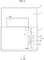
- the sensor part 6 is disposed in a region 10.
- the region 10 is positioned toward the positive direction of the X axis than the flow path device 2.
- the flow path device 2 includes the storage chamber 41, a flow path 48, an inlet 50, and a projection 51.
- the flow path device 2 includes projecting portions 49A and 49B (a pair of projecting portions).
- the base plate 5 includes an upper base plate 20, a small plate 30, a sheet member 36, and a lower base plate 40.
- the upper base plate 20 is positioned above the lower base plate 40.
- the upper base plate 20 may be made of, for example, a synthetic resin material.
- the upper base plate 20 includes an accommodation portion 25, an inner surface 23 and a wall surface 24 that form the accommodation portion 25, an opening portion 22 that extends through an outer portion of the base plate 5 and the accommodation portion 25, and a wall surface 21 that forms the opening portion 22.
- the opening portion 22 is specified as a region that is surrounded by the wall surface 21. As shown in Fig. 2 , in top view, the opening portion 22 may be, for example, circular.
- the accommodation portion 25 is specified as a region that is surrounded by the inner surface 23 and the wall surface 24.
- the small plate 30 is accommodated in the accommodation portion 25.
- the size and the shape of the accommodation portion 25 may be adjusted as appropriate in accordance with the size of the small plate 30.
- the small plate 30 is positioned between the upper base plate 20 and the lower base plate 40.
- the small plate 30 is accommodated in the accommodation portion 25 of the upper base plate 20.
- the small plate 30 may be made of, for example, a synthetic resin material.
- the small plate 30 has an upper surface 31, a lower surface 32, an opening portion 33 that extends through the upper surface 31 and the lower surface 32, and a wall surface 34 that forms the opening portion 33.
- the upper surface 31 faces the inner surface 23 of the upper base plate 20.
- a bonding member 35 may be disposed as appropriate between the upper surface 31 and the inner surface 23 of the upper base plate 20.
- the bonding member 35 may be any adhesive selected as appropriate in accordance with the material of the small plate 30 and the material of the upper base plate 20.
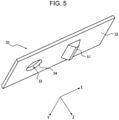
- the lower surface 32 faces the lower base plate 40. As shown in Fig. 5 , the projection 51 is disposed on the lower surface 32.
- the opening portion 33 is specified as a region that is surrounded by the wall surface 34. As shown in Fig. 4 , the opening portion 33 may be circular in top view. As shown in Fig. 3 , the inside diameter of the opening portion 33 may be smaller than the inside diameter of the opening portion 22 of the upper base plate 20. The inside diameter of the opening portion 33 may be adjusted as appropriate in accordance with the outside diameter of an end portion 84 of a syringe 81 of an air push-out unit 80 described below ( Fig. 6 ).
- the sheet member 36 is disposed to cover a gap between the wall surface 24 of the upper base plate 20 and an end portion of the small plate 30 from below the gap.
- the sheet member 36 may be made of, for example, synthetic resin.
- the lower base plate 40 is positioned below the upper base plate 20.
- the lower base plate 40 may be made of, for example, a synthetic resin material.
- the lower base plate 40 may have a recessed portion 40A that opens upward.
- the recessed portion 40A has a bottom surface 43, a bottom surface 41a, a bottom surface 46, a wall surface 44, a wall surface 41b, and a wall surface 47.
- the storage chamber 41 shown in Fig. 3 is specified as a region that is surrounded by the lower surface 32 of the small plate 30 and the surfaces of the recessed portion 40A shown in Fig. 4 .
- the storage chamber 41 is specified as a region that is surrounded by the lower surface 32 of the small plate 30 shown in Fig. 3 , the bottom surface 41a, the bottom surface 43, and the bottom surface 46 of the recessed portion 40A shown in Fig. 4 , and the wall surface 41b, the wall surface 44, and the wall surface 47 of the recessed portion 40A.
- a portion that specifies the storage chamber 41 may also be called a "ceiling surface" of the storage chamber 41.
- the storage chamber 41 is positioned in the base plate 5.
- the storage chamber 41 communicates with the outside of the base plate 5 through the inlet 50 including the opening portion 22 and the opening portion 33. In other words, the storage chamber 41 communicates with the outside of the storage chamber 41 through the inlet 50.
- the storage chamber 41 is capable of storing the specimen 7.
- the specimen 7 dripped toward the inlet 50 by a user is supplied to the storage chamber 41 through the inlet 50.
- the storage chamber 41 stores the specimen 7 supplied through the inlet 50.
- the specimen 7 can accumulate at a lower side of the storage chamber 41 due to gravity acting upon the specimen 7.
- the specimen 7 is stored in the storage chamber 41 until the sensor part 6 shown in Fig. 2 starts to measure the specimen 7.
- the sensor part 6 shown in Fig. 2 starts to measure the specimen 7
- the specimen 7 stored in the storage chamber 41 is supplied to the sensor part 6 in the region 10 through the flow path 48 shown in Fig. 2 .
- the storage chamber 41 may include a first chamber 42 and a second chamber 45.
- the storage chamber 41 may have a space 41A between the first chamber 42 and the second chamber 45.
- the space 41A includes a portion that is specified as a region that is surrounded by the bottom surface 41a and the wall surface 41b.
- the first chamber 42 and the second chamber 45 communicate with each other through the space 41A.
- the projection 51 is positioned in the space 41A. By positioning the projection 51 in the space 41A, as described below, a large amount of the specimen 7 shown in Fig. 3 can be held back at the first chamber 42 in the storage chamber 41.
- the first chamber 42 is specified as a region that is surrounded by the lower surface 32 of the small plate 30, the bottom surface 43, and the wall surface 44. A part of an upper portion of the first chamber 42 communicates with the inlet 50. As shown in Fig. 4 , a part of the first chamber 42 toward the positive direction of the X axis communicates with the second chamber 45 through the space 41A. As shown in Fig. 3 , the specimen 7 that has flowed in from the inlet 50 can be stored in the first chamber 42.
- a side of the bottom surface 43 toward the positive direction of the X axis is continuous with the bottom surface 41a of the space 41A.
- a part of the bottom surface 43 toward the positive direction of the X axis may be a plane surface along an XY plane.
- a part of the bottom surface 43 toward the negative direction of the X axis may be an inclined surface that inclines toward the negative direction of the Z axis as this part extends toward the negative direction of the X axis.
- the wall surface 44 is connected to the wall surface 41b of the space 41A.
- the bottom surface 43 may have a substantially rectangular shape extending along the XY plane.
- the wall surface 44 may extend along the negative direction of the Z axis from a part of a periphery of the bottom surface 43. That is, the shape of the first chamber 42 may be a substantially rectangular parallelepiped shape.
- the capacity of the first chamber 42 can be increased. By increasing the capacity of the first chamber 42, even if the specimen 7 is a specimen whose amount is relatively large, such as a person's urine, the first chamber 42 is capable of storing the specimen 7.
- the probability with which the specimen 7 overflows the first chamber 42, flows through the second chamber 45, and flows out into the flow path 48 can be reduced. Due to such a structure, the probability with which the specimen 7 stored in the storage chamber 41 reaches the sensor part 6 shown in Fig. 2 through the flow path 48 before the sensor part 6 shown in Fig. 2 starts to measure the specimen 7 can be reduced.
- the second chamber 45 is specified as a region that is surrounded by the lower surface 32 of the small plate 30, the bottom surface 46, and the wall surface 47. An upper portion of the second chamber 45 toward the positive direction of the X axis communicates with the flow path 48.
- a side of the bottom surface 46 toward the negative direction of the X axis is continuous with the bottom surface 41a of the space 41A.
- the wall surface 47 is continuous with the wall surface 41b of the space 41A.
- the length (width) of the bottom surface 46 in the direction along the Y axis may gradually decrease toward the flow path 48.
- the wall surface 47 may extend along the negative direction of the Z axis from a part of a periphery of the bottom surface 46. That is, the width of the second chamber 45 may become gradually smaller toward the flow path 48 from a location where the projection 51 is positioned.
- the bottom surface 46 may be an inclined surface that inclines toward the flow path 48 from the bottom surface 41a of the space 41A.
- the capacity of the storage chamber 41 can be set based on the quantity of air that is capable of being supplied by the air push-out unit 80 (described later) ( Fig. 6 ). That is, the sum of the capacity of the first chamber 42 and the capacity of the second chamber 45 can be set based on the quantity of air that is capable of being supplied by the air push-out unit 80 (described later) ( Fig. 6 ).
- the capacity of the second chamber 45 is reduced, as a result of which the capacity of the first chamber 42 can be increased by an amount corresponding to the decrease in the capacity of the second chamber 45.
- the probability with which the specimen 7 overflows the first chamber 42, flows through the second chamber 45, and flows out into the flow path 48 can be reduced.
- the flow path 48 is positioned in the base plate 5.
- the flow path 48 is specified as a region that is surrounded by a groove in the lower base plate 40 and a lower surface of the upper base plate 20 or the sheet member 36.
- the flow path 48 is connected to the storage chamber 41 at a location situated away from the inlet 50.
- the flow path 48 is connected to the second chamber 45 of the storage chamber 41.
- the flow path 48 extends from the storage chamber 41 to the region 10 where the sensor part 6 is disposed. In other words, the sensor part 6 is connected to the flow path 48.
- the specimen 7 can flow out into the flow path 48 from the storage chamber 41.
- air is sent out into the storage chamber 41 by the air push-out unit 80 described below ( Fig. 7 ).
- the specimen 7 flows out into the flow path 48 from the storage chamber 41 by the air sent out into the storage chamber 41.
- the specimen 7 that has flowed out into the flow path 48 reaches the sensor part 6 shown in Fig. 2 through the flow path 48.
- the flow path 48 is connected to an upper portion of the storage chamber 41.
- the flow path 48 is connected to the upper portion of the second chamber 45 of the storage chamber 41.
- the specimen 7 can accumulate at the lower side of the storage chamber 41 due to gravity acting upon the specimen 7. Since the specimen 7 accumulates at the lower side of the storage chamber 41, by connecting the flow path 48 to the upper portion of the storage chamber 41, the probability with which the specimen 7 flows into the flow path 48 before the sensor part 6 shown in Fig. 2 starts to measure the specimen 7 can be reduced. Due to such a structure, the probability with which the specimen 7 reaches the sensor part 6 shown in Fig. 2 through the flow path 48 before the sensor part 6 starts to measure the specimen 7 can be reduced.
- the projecting portions 49A and 49B are positioned at a portion of the first chamber 42 toward the second chamber 45.
- the projecting portions 49A and 49B may each be formed as a part of the lower base plate 40.
- the projecting portions 49A and 49B face each other.
- the projecting portion 49A projects toward the negative direction of the Y axis.
- the projecting portion 449 projects toward the positive direction of the Y axis.
- the inlet 50 has the opening portion 22 of the upper base plate 20 and the opening portion 33 of the small plate 30. That is, the inlet 50 includes a portion that is specified as a region that is surrounded by the wall surface 21 of the upper base plate 20 and a portion that is specified as a region that is surrounded by the wall surface 34 of the small plate 30.
- the inlet 50 is positioned in the base plate 5.
- the inlet 50 causes the outside of the base plate 5 and the storage chamber 41 to communicate with each other to allow the specimen 7 to flow into the storage chamber 41 from the outside of the base plate 5.
- the inlet 50 causes the outside of the storage chamber 41 and the storage chamber 41 to communicate with each other to allow the specimen 7 to flow into the storage chamber 41 from the outside of the storage chamber 41.
- a user drips the specimen 7 toward the inlet 50 from a side of the negative direction of the Z axis.
- the specimen 7 dripped toward the inlet 50 can flow into the storage chamber 41 from the inlet 50.
- the projection 51 is positioned in the base plate 5.
- the projection 51 is positioned on the lower surface 32 of the small plate 30.
- the projection 51 may be integrated with the small plate 30.
- the projection 51 projects toward the bottom surface 41a of the space 41A of the storage chamber 41 from the lower surface 32 of the small plate 30, which is the ceiling surface of the storage chamber 41.
- the projection 51 may have a substantially inverted triangular shape whose apex is positioned toward the bottom surface 41a of the storage chamber 41.
- the projection 51 limits a space with which a space of the storage chamber 41 toward the inlet 50 and a space of the storage chamber 41 toward the flow path 48 communicate to a height less than or equal to a predetermined height from a bottom surface of the storage chamber 41.
- the projection 51 limits the space 41A with which the first chamber 42 as a space of the storage chamber 41 toward the inlet 50 and the second chamber 45 as a space of the storage chamber 41 toward the flow path 48 communicate to a height less than or equal to the predetermined height from the bottom surface 41a of the storage chamber 41.
- the surface tension of the specimen 7 makes it difficult for the specimen 7 to leak and spread toward the flow path 48 at a location between the projection 51 and the bottom surface 46.
- a large amount of the specimen 7 can be held back at the first chamber 42 in the storage chamber 41.
- the probability with which the specimen 7 flows into the second chamber 45 of the storage chamber 41 before the sensor part 6 shown in Fig. 2 starts to measure the specimen 7 can be reduced.
- the probability with which the specimen 7 flows into the second chamber 45 of the storage chamber 41 By reducing the probability with which the specimen 7 flows into the second chamber 45 of the storage chamber 41, the probability with which the specimen 7 reaches the sensor part 6 shown in Fig. 2 through the flow path 48 before the sensor part 6 shown in Fig. 2 starts to measure the specimen 7 can be reduced.
- a liquid surface of the specimen 7 at the first chamber 42 can be positioned above a lower portion of the projection 51. Due to the liquid surface of the specimen 7 at the first chamber 42 being positioned above the lower portion of the projection 51, as described below, the specimen 7 can be efficiently supplied to the sensor part 6 when the sensor part 6 shown in Fig. 2 starts to measure the specimen 7.
- the predetermined height above may be set as appropriate by considering how easily the specimen 7 at the storage chamber 41 leaks and spreads.
- the predetermined height may be set as appropriate based on the material of the lower base plate 40 and the surface tension of the specimen 7.
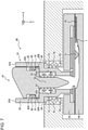
- Fig. 6 is a sectional view of a disposed state of the cartridge 4 shown in Fig. 1 in the measurement apparatus 3.
- Fig. 7 is a sectional view of another example of a disposed state of the cartridge 4 shown in Fig. 1 in the measurement apparatus 3.
- the measurement apparatus 3 shown in Fig. 1 includes a case 60 shown in Fig. 6 and the air push-out unit 80 shown in Fig. 6 .
- the measurement apparatus 3 may include, for example, a heater or a cooler for controlling the temperature of the specimen 7 or the like, and a controller.
- the controller of the measurement apparatus 3 may be constituted by, for example, a processor or a microcomputer capable of executing application software.
- the controller of the measurement apparatus 3 may measure, for example, a component in the specimen 7 based on an electric signal output by the sensor part 6.
- the case 60 shown in Fig. 6 is disposed in the housing 3A of the measurement apparatus 3 shown in Fig. 1 .
- the case 60 may be made of, for example, a metal material or a synthetic resin material.
- the flow path device 2 is disposed in the case 60 shown in Fig. 6 .
- the case 60 includes an accommodation portion 70.
- the accommodation portion 70 is specified as a region that is surrounded by a wall surface 61, a wall surface 62, and a bottom surface 63.
- the wall surface 61 and the wall surface 62 face each other.
- One end of the wall surface 61 toward the positive direction of the Z axis and one end of the wall surface 62 toward the positive direction of the Z axis are each continuous with the bottom surface 63.
- the accommodation portion 70 accommodates a first spring 86 described below.
- the air push-out unit 80 includes the syringe 81 having an upper surface 81A and a plunger 87 having a contact surface 88.
- the upper surface 81A of the syringe 81 is pushed downward by the measurement apparatus 3.
- the contact surface 88 of the plunger 87 is pushed downward by the measurement apparatus 3.
- the plunger 87 is pushed downward.
- the structure shown in Fig. 7 is a structure when, in addition to the syringe 81, the plunger 87 is pushed downward by the measurement apparatus 3. Note that, when the measurement on the specimen 7 shown in Fig. 1 ends, the measurement apparatus 3 shown in Fig. 1 stops pushing the upper surface 81A of the syringe 81 downward and stops pushing the contact surface 88 of the plunger 87 downward.
- the syringe 81 has a cylindrical shape.
- the syringe 81 may be made of, for example, a synthetic resin material or a glass material.
- the syringe 81 has the upper surface 81A as described above.
- the syringe 81 further includes a body portion 82, an intermediate portion 83, the end portion 84, a first seal member 85, and the first spring 86.
- the plunger 87 is movable in the syringe 81, and is capable of pushing out air in the syringe 81 to the end portion 84.
- the plunger 87 may be made of a synthetic resin material or a glass material.
- the plunger 87 has the contact surface 88 as described above.
- the plunger 87 further includes a shaft portion 89, a second seal member 90, a flange portion 91, a rod-like portion 92, and a second spring 93.
- the upper surface 81A faces upward.
- the upper surface 81A can be pushed downward by the measurement apparatus 3 shown in Fig. 1 as described above. By pushing the upper surface 81A downward by the measurement apparatus 3, the syringe 81 can be pushed downward.
- the upper surface 81A may be the upper surface of the body portion 82.
- the body portion 82 may have a cylindrical shape.
- the body portion 82 may have an inner peripheral surface 82A, a fixing surface 82B, and a lower surface 82C.
- the inner peripheral surface 82A faces the plunger 87.
- the fixing surface 82B faces upward.
- An outer peripheral end of the fixing surface 82B is continuous with a lower portion of the inner peripheral surface 82A.
- the fixing surface 82B abuts upon a lower surface of the flange portion 91 of the plunger 87. Due to the fixing surface 82B abutting upon the lower surface of the flange portion 91 of the plunger 87, the plunger 87 is fixed.
- the lower surface 82C is continuous with an outer peripheral surface of the body portion 82 and an outer peripheral surface of the intermediate portion 83. The lower surface 82C faces downward.
- the intermediate portion 83 shown in Fig. 6 may have a cylindrical shape. In a direction along the Z axis, the intermediate portion 83 is positioned between the body portion 82 and the end portion 84.
- the inside diameter of the intermediate portion 83 is smaller than the inside diameter of the body portion 82.
- the inside diameter of the intermediate portion 83 is larger than the inside diameter of the end portion 84.
- the first spring 86 may be disposed around the intermediate portion 83.
- the intermediate portion 83 has an inner peripheral surface 83A and a fixing surface 83B.
- the inner peripheral surface 83A faces the plunger 87.
- An upper portion of the inner peripheral surface 83A is continuous with an inner peripheral end of the fixing surface 82B of the body portion 82.
- the fixing surface 83B faces upward.
- An outer peripheral end of the fixing surface 83B is continuous with a lower portion of the inner peripheral surface 83A.
- the end portion 84 may have a cylindrical shape.
- the end portion 84 can be inserted into the inlet 50. For example, when the syringe 81 is pushed downward by the measurement apparatus 3 shown in Fig. 1 , as shown in Fig. 6 , the end portion 84 is inserted into the inlet 50.
- the first seal member 85 is disposed on the end portion 84.
- the first seal member 85 may be an O ring made of a flexible material, such as rubber.
- the first seal member 85 may be disposed along an entire lower surface of the end portion 84.
- the first seal member 85 is capable of hermetically sealing a location between the end portion 84 and the storage chamber 41. For example, when the syringe 81 is pushed downward, as shown in Fig. 6 , the first seal member 85 can abut upon a portion of the upper surface 31 of the small plate 30 surrounding the wall surface 34 of the small plate 30. Due to the first seal member 85 abutting upon the portion of the upper surface 31 of the small plate 30 surrounding the wall surface 34 of the small plate 30, the location between the end portion 84 and the storage chamber 41 is hermetically sealed.
- the first spring 86 is disposed around the intermediate portion 83.
- the first spring 86 may be, for example, a coil spring.
- the first spring 86 may be wound around the outer peripheral surface of the intermediate portion 83.
- One end of the first spring 86 is fixed to the lower surface 82C of the body portion 82.
- the other end of the first spring 86 is a free end.
- the other end of the first spring 86 is pushed against the bottom surface 63 of the accommodation portion 70.
- the first spring 86 By pushing the other end of the first spring 86 against the bottom surface 63 of the accommodation portion 70, the first spring 86 is compressed.
- the measurement apparatus 3 stops pushing the upper surface 81A of the syringe 81 downward as a result of ending the measurement on the specimen 7 shown in Fig. 1 , the first spring 86 expands.
- an elastic force that moves the syringe 81 upward is applied to the syringe 81.
- the elastic force to the syringe 81 by the first spring 86 after the measurement apparatus 3 shown in Fig. 1 stops pushing the upper surface 81A of the syringe 81 downward, the syringe 81 moves upward and returns to its original position.
- the contact surface 88 is positioned above the shaft portion 89. As described above, the contact surface 88 can be pushed downward by the measurement apparatus 3 shown in Fig. 1 . When the contact surface 88 is pushed downward by the measurement apparatus 3 shown in Fig. 1 , as shown in Fig. 7 , the plunger 87 is pushed downward. When the plunger 87 is pushed downward, as shown in Fig. 7 , air in the syringe 81 is sent out into the storage chamber 41. For example, when the plunger 87 is pushed downward, air in a portion of a region surrounded by the inner peripheral surface 82A of the body portion 82 shown in Fig.
- the specimen 7 flows into the flow path 48 and is supplied to the sensor part 6 shown in Fig. 2 .
- the contact surface 88 may be an inclined surface that inclines toward the positive direction of the Z axis with respect to the XY plane.
- the contact surface 88 can be gradually pushed downward by the measurement apparatus 3 shown in Fig. 1 .
- the plunger 87 is capable of gradually moving downward.
- air in the syringe 81 can be gradually sent out into the storage chamber 41.
- the shaft portion 89 may have a columnar shape.
- the contact surface 88 is positioned above the shaft portion 89.
- the flange portion 91 and the rod-like portion 92 are positioned below the shaft portion 89.
- the second seal member 90 is disposed around the shaft portion 89.
- the second seal member 90 may be an O ring made of a flexible material, such as rubber.
- the second seal member 90 is capable of hermetically sealing a location between the shaft portion 89 and the inner peripheral surface 82A of the body portion 82.
- the syringe 81 can contain a larger amount of air in the region surrounded by the inner peripheral surface 82A of the body portion 82.
- the flange portion 91 is disposed at a lower portion of the shaft portion 89.
- the flange portion 91 projects toward the inner peripheral surface 82A of the body portion 82 from the shaft portion 89. As shown in Fig. 7 , when the plunger 87 is pushed downward, the lower surface of the flange portion 91 abuts upon the fixing surface 82B of the body portion 82.
- the rod-like portion 92 is positioned at a lower portion of the flange portion 91.
- the second spring 93 is disposed around the rod-like portion 92.
- the second spring 93 may be, for example, a coil spring.
- the second spring 93 may be wound around an outer peripheral surface of the rod-like portion 92.
- One end of the second spring 93 is fixed to the lower portion of the flange portion 91.
- the other end of the second spring 93 is fixed to the fixing surface 83B of the intermediate portion 83. As shown in Fig.
- a user drips the specimen 7 toward the inlet 50 of the flow path device 2.
- the specimen 7 dripped toward the inlet 50 is stored in the storage chamber 41.
- a large amount of the specimen 7 can be held back at the first chamber 42 in the storage chamber 41 by the projection 51.
- the probability with which the specimen 7 flows into the second chamber 45 of the storage chamber 41 can be reduced.
- by connecting the flow path 48 to the upper portion of the storage chamber 41 the probability with which the specimen 7 accumulated at the lower side of the storage chamber 41 flows into the flow path 48 can be reduced.
- the cartridge 4 including the flow path device 2 is inserted into the insertion hole 3B of the measurement apparatus 3.
- the cartridge 4 that has been inserted from the insertion hole 3B of the measurement apparatus 3 shown in Fig. 1 is disposed in the case 60 shown in Fig. 6 .
- the sensor part 6 shown in Fig. 2 starts to measure the specimen 7.
- the upper surface 81A of the syringe 81 shown in Fig 6 is pushed downward by the measurement apparatus 3 shown in Fig. 1 .
- the syringe 81 moves downward.
- the end portion 84 of the syringe 81 is inserted into the inlet 50 of the flow path device 2 as shown in Fig. 6 .
- the liquid surface of the specimen 7 in the second chamber 45 continues to rise. Due to the continued rising of the liquid surface of the specimen 7 in the second chamber 45, the liquid surface reaches the position of the flow path 48.
- the bottom surface 46 may be an inclined surface that inclines toward the flow path 48 from the bottom surface 41a of the space 41A. Due to the bottom surface 46 being an inclined surface that inclines towards the flow path 48, the specimen 7 can smoothly flow toward the flow path 48 from the second chamber 45.
- the plunger 87 moves downward until the lower surface of the flange portion 91 of the plunger 87 abuts upon the fixing surface 82B of the syringe 81.
- air from the air push-out unit 80 passes below the projection 51.
- the air that has passed below the projection 51 pushes out the specimen 7 in the second chamber 45 toward the positive direction of the X axis.
- the projection 51 may have in sectional view a substantially inverted triangular shape whose apex is positioned toward the bottom surface 41a of the storage chamber 41.
- the projection 51 having a substantially inverted triangular shape, air that flows in the upper portion of the first chamber 42 of the storage chamber 41 can be smoothly guided to a location below the projection 51 by an oblique surface of the projection 51. Due to the air being smoothly guided to a location below the projection 51 by the oblique surface of the projection 51, the air is capable of efficiently pushing out the specimen 7 in the second chamber 45 toward the positive direction of the X axis.
- the measurement apparatus 3 shown in Fig. 1 stops pushing the upper surface 81A of the syringe 81 shown in Fig. 7 downward and stops pushing the contact surface 88 of the plunger 87 shown in Fig. 7 downward.
- the syringe 81 can be returned to its original position by the first spring 86 shown in Fig. 7 .
- the plunger 87 can be returned to its original position by the second spring 93 shown in Fig. 7 .
- the flow path device 2 since the flow path device 2 according to the present embodiment includes the projection 51, as described below, it is possible to easily control a timing of supplying the specimen 7 to the sensor part 6.
- Fig. 10 is a sectional view of a measurement system 1X according to a comparative example.
- the measurement system 1X includes a flow path device 2X. Unlike the flow path device 2 shown in Fig. 6 , the flow path device 2X does not include a projection 51.
- a specimen 7 can spread over the entire bottom surface of a storage chamber 41.
- the flow path 48 is connected to an upper portion of the storage chamber 41.
- a large amount of the specimen 7 can be held back at the first chamber 42 in the storage chamber 41 by the projection 51.
- a liquid surface of the specimen 7 in the first chamber 42 can be positioned above the lower portion of the projection 51.
- a space portion of the first chamber 42 above the liquid surface of the specimen 7, excluding the inlet 50 can become a closed space. Due to such a structure, as shown in Fig. 8 , air that has flowed in from the inlet 50 can reliably push the liquid surface of the specimen 7 in the first chamber 42 downward.
- the specimen 7 can reach the sensor part 6 shown in Fig. 2 through the flow path 48.
- the flow path device 2 and the measurement system 1 that are capable of easily controlling a timing of supplying the specimen 7 to the sensor part 6.
- a mechanism for sending out air to the storage chamber 41 does not need to be disposed at the flow path device 2 at a location differing from the location of the storage chamber 41.
- a mechanism for sending out air to the storage chamber 41 does not need to be disposed at the flow path device 2, it is possible to reduce the size of the flow path device 2 in the XY plane.
- the measurement system 1 is capable of more precisely measuring, for example, a component of the specimen 7.
- the lower surface 32 of the small plate 30 can be used as the ceiling surface of the storage chamber 41.
- the small plate 30 is a component that differs from the lower base plate 40 having the bottom surfaces 43 and 46 and the wall surfaces 44 and 45 of the storage chamber 41.
- the storage chamber 41 is less likely to be influenced by surface accuracy. Due to the storage chamber 41 being less likely to be influenced by surface accuracy, it is possible to increase the ability with which the storage chamber 41 is sealed.
- one end of the first spring 86 shown in Fig. 6 has been described as being fixed to the lower surface 82C of the body portion 82 of the syringe 81.
- the one end of the first spring 86 may not be fixed to the lower surface 82C.
- the first spring 86 only needs to be disposed around the syringe 81.
- one end of the second spring 93 shown in Fig. 6 has been described as being fixed to the lower portion of the flange portion 91.
- the other end of the second spring 93 has been described as being fixed to the fixing surface 83B of the intermediate portion 83.
- the one end of the second spring 93 may not be fixed to the lower portion of the flange portion 91.
- the other end of the second spring 93 may not be fixed to the fixing surface 83B of the intermediate portion 83.
- the second spring 93 only needs to be disposed around the rod-like portion 92 of the plunger 87.
- the projection 51 shown in Fig. 3 has been described as limiting the space 41A to a height less than or equal to the predetermined height from the bottom surface 41a of the storage chamber 41.
- the predetermined height above may be set as appropriate by considering how easily the specimen 7 in the storage chamber 41 leaks and spreads.
- the setting of the predetermined height is not limited thereto.
- the predetermined height may be set to position the liquid surface of the specimen 7 in the first chamber 42 above the lower portion of the projection 51.
- a flow path device 102 shown in Fig. 11 includes a projection 151.
- the projection 51 shown in Fig. 11 includes a projection 151.
- the projection 151 limits a space 41A to a height less than or equal to a predetermined height from a bottom surface 41a of a storage chamber 41.
- the predetermined height is set to position a liquid surface of a specimen 7 in a first chamber 42 above a lower portion of the projection 151.
- the predetermined height may be calculated based on the area of the bottom surface of the entire storage chamber 41 and an assumed amount of the specimen 7.
- the predetermined height is set to position the liquid surface of the specimen 7 in the first chamber 42 above the lower portion of the projection 151. Due to such a structure, in the structure shown in Fig.
- a space portion of the first chamber 42 above the liquid surface of the specimen 7, excluding an inlet 50 can become a closed space. Due to the space portion of the first chamber 42 above the liquid surface of the specimen 7, excluding the inlet 50, becoming a closed space, as described above with reference to Fig. 8 , in the flow path device 102, air that has flowed in from the inlet 50 can reliably push the liquid surface of the specimen 7 in the first chamber 42 downward. As described above with reference to Fig. 8 , in the flow path device 102, by pushing the liquid surface of the specimen 7 in the first chamber 42 downward, the specimen 7 can reach the sensor part 6 shown in Fig. 2 through the flow path 48.
- first and “second” in the present disclosure are identifiers for distinguishing between corresponding structures.
- the structures that are distinguished by, for example, “first” and “second” in the present disclosure can have their numbers exchanged.
- “the first” in the first chamber, which distinguishes the first chamber from the second chamber, can be replaced by "the second".
- the identifiers are exchanged at the same time. After the replacement of the identifiers, the structures are distinguished from each other.
- the identifiers may be deleted.
- the structures whose identifiers have been deleted are distinguished by their reference signs. Identifiers, such as "first" and "second”, in the present disclosure alone should not be used to interpret the order of the corresponding structures or used as a basis for the existence of identifiers containing small numbers.
Landscapes
- Health & Medical Sciences (AREA)
- Chemical & Material Sciences (AREA)
- Life Sciences & Earth Sciences (AREA)
- Analytical Chemistry (AREA)
- General Health & Medical Sciences (AREA)
- Physics & Mathematics (AREA)
- Immunology (AREA)
- Engineering & Computer Science (AREA)
- Pathology (AREA)
- Biochemistry (AREA)
- General Physics & Mathematics (AREA)
- Hematology (AREA)
- Biomedical Technology (AREA)
- Clinical Laboratory Science (AREA)
- Chemical Kinetics & Catalysis (AREA)
- Molecular Biology (AREA)
- Urology & Nephrology (AREA)
- Food Science & Technology (AREA)
- Medicinal Chemistry (AREA)
- Dispersion Chemistry (AREA)
- Biotechnology (AREA)
- Cell Biology (AREA)
- Microbiology (AREA)
- Biophysics (AREA)
- Sampling And Sample Adjustment (AREA)
- Automatic Analysis And Handling Materials Therefor (AREA)
Abstract
Description
- The present application claims priority to
Japanese Patent Application No. 2019-084488, filed in Japan on April 25, 2019 - The present disclosure relates to a flow path device, a cartridge, and a measurement system.
- Hitherto, a known testing instrument has included a specimen supply port, a measurement chamber, and a flow path through which the specimen supply port and the measurement chamber communicate with each other (PTL 1).
- PTL 1:
Japanese Unexamined Patent Application Publication No. 2002-224090 - A flow path device according to an embodiment of the present disclosure includes
- a storage chamber that includes a ceiling surface and a bottom surface, and that is capable of storing a specimen;
- an inlet through which an outside of the storage chamber and the storage chamber communicate with each other to allow the specimen to flow into the storage chamber from the outside of the storage chamber;
- a flow path that is connected to an upper portion of the storage chamber at a location situated away from the inlet, the specimen being allowed to flow out into the flow path from the storage chamber; and
- a projection that projects toward the bottom surface of the storage chamber from the ceiling surface of the storage chamber, and that is positioned between the inlet and the flow path,
- wherein the projection limits a space with which a space of the storage chamber toward the inlet and a space of the storage chamber toward the flow path communicate to a height less than or equal to a predetermined height from the bottom surface of the storage chamber.
- A cartridge according to an embodiment of the present disclosure includes
- the flow path device; and
- a sensor part that is connected to the flow path of the flow path device.
- A measurement system according to an embodiment of the present disclosure includes
- the cartridge; and
- an air push-out unit,
- wherein the air push-out unit includes
- a cylindrical syringe that comprises an end portion insertable into the inlet, and
- a plunger that is movable in the syringe and that is capable of pushing out air in the syringe to the end portion.
-
- [
Fig. 1] Fig. 1 is a schematic view of a measurement system according to an embodiment of the present disclosure. - [
Fig. 2] Fig. 2 is a top view of a cartridge shown inFig. 1 . - [
Fig. 3] Fig. 3 is a sectional view of a flow path device along line L-L shown inFig. 2 . - [
Fig. 4] Fig. 4 is an exploded view of a part of the flow path device shown inFig. 3 . - [
Fig. 5] Fig. 5 is a perspective view of a third base plate shown inFig. 4 . - [
Fig. 6] Fig. 6 is a sectional view of a disposed state of the cartridge shown inFig. 1 in a measurement apparatus. - [
Fig. 7] Fig. 7 is a sectional view of another example of a disposed state of the cartridge shown inFig. 1 in the measurement apparatus. - [
Fig. 8] Fig. 8 is a sectional view of a structure when a plunger shown inFig. 6 has moved downward. - [
Fig. 9] Fig. 9 is a sectional view of a structure when the plunger shown inFig. 8 has moved downward. - [
Fig. 10] Fig. 10 is a sectional view of a measurement system according to a comparative example. - [
Fig. 11] Fig. 11 is a sectional view of another example of the flow path device shown inFig. 3 . Description of Embodiments - A testing instrument is required to, for example, control a timing of supplying a specimen to a measurement chamber.
- The present disclosure relates to providing a flow path device, a cartridge, and a measurement system that are capable of easily controlling a timing of supplying a specimen to a sensor part.
- The flow path device, the cartridge, and the measurement system according to an embodiment of the present disclosure are capable of easily controlling a timing of supplying a specimen to the sensor part.
- An embodiment according to the present disclosure is described below with reference to the drawings. In the drawings below, the direction of insertion of a
flow path device 2 shown inFig. 1 into a measurement apparatus 3 is a positive direction of an X axis. The direction in which gravity acts is a position direction of a Z axis. A positive direction of a Y axis is determined to form a right-handed orthogonal coordinate system. - Here, in the present disclosure, "down" means the direction in which gravity acts, that is, the positive direction of the Z axis. In the present disclosure, "up" means a direction opposite to the direction in which gravity acts, that is, a negative direction of the Z axis.
- As shown in
Fig. 1 , ameasurement system 1 includes the measurement apparatus 3 and acartridge 4. Thecartridge 4 includes abase plate 5. Thecartridge 4 includes theflow path device 2 and asensor part 6 at thebase plate 5. Thesensor part 6 may be constituted as a separate member from thebase plate 5. Thesensor part 6 may be disposed at the measurement apparatus 3. - The
flow path device 2 includes astorage chamber 41 described below. Thestorage chamber 41 stores aspecimen 7. Examples of thespecimen 7 include a person's blood, a person's cerebrospinal fluid, and a person's urine. Note that before introducing thespecimen 7 into theflow path device 2, thespecimen 7 may be pre-treated as appropriate. - The measurement apparatus 3 includes a
housing 3A and aninsertion hole 3B. Thehousing 3A may be made of, for example, a metal material or a synthetic resin material. - The
cartridge 4 is inserted into the measurement apparatus 3 from theinsertion hole 3B. By inserting thecartridge 4 from theinsertion hole 3B of the measurement apparatus 3, thecartridge 4 is disposed in the measurement apparatus 3. When thecartridge 4 is disposed in the measurement apparatus 3, as described below, thespecimen 7 is supplied to thesensor part 6. Thesensor part 6 outputs an electric signal in accordance with a component in thespecimen 7. - The
sensor part 6 may be constituted by, for example, a sensor using a surface acoustic wave (SAW). The measurement apparatus 3 obtains the electric signal output by thesensor part 6. The measurement apparatus 3 measures, for example, the component in thespecimen 7 based on, for example, the obtained electric signal. - As shown in
Fig. 2 , thesensor part 6 is disposed in aregion 10. At thebase plate 5, theregion 10 is positioned toward the positive direction of the X axis than theflow path device 2. - As shown in
Fig. 3 , theflow path device 2 includes thestorage chamber 41, aflow path 48, aninlet 50, and aprojection 51. As shown inFig. 4 , theflow path device 2 includes projectingportions Fig. 3 , thebase plate 5 includes anupper base plate 20, asmall plate 30, asheet member 36, and alower base plate 40. - The
upper base plate 20 is positioned above thelower base plate 40. Theupper base plate 20 may be made of, for example, a synthetic resin material. Theupper base plate 20 includes anaccommodation portion 25, aninner surface 23 and awall surface 24 that form theaccommodation portion 25, an openingportion 22 that extends through an outer portion of thebase plate 5 and theaccommodation portion 25, and awall surface 21 that forms the openingportion 22. - The opening
portion 22 is specified as a region that is surrounded by thewall surface 21. As shown inFig. 2 , in top view, the openingportion 22 may be, for example, circular. - The
accommodation portion 25 is specified as a region that is surrounded by theinner surface 23 and thewall surface 24. Thesmall plate 30 is accommodated in theaccommodation portion 25. The size and the shape of theaccommodation portion 25 may be adjusted as appropriate in accordance with the size of thesmall plate 30. - The
small plate 30 is positioned between theupper base plate 20 and thelower base plate 40. Thesmall plate 30 is accommodated in theaccommodation portion 25 of theupper base plate 20. Thesmall plate 30 may be made of, for example, a synthetic resin material. As shown inFigs. 4 and5 , thesmall plate 30 has anupper surface 31, alower surface 32, an openingportion 33 that extends through theupper surface 31 and thelower surface 32, and awall surface 34 that forms the openingportion 33. - As shown in
Fig. 3 , theupper surface 31 faces theinner surface 23 of theupper base plate 20. A bondingmember 35 may be disposed as appropriate between theupper surface 31 and theinner surface 23 of theupper base plate 20. The bondingmember 35 may be any adhesive selected as appropriate in accordance with the material of thesmall plate 30 and the material of theupper base plate 20. Thelower surface 32 faces thelower base plate 40. As shown inFig. 5 , theprojection 51 is disposed on thelower surface 32. - The opening
portion 33 is specified as a region that is surrounded by thewall surface 34. As shown inFig. 4 , the openingportion 33 may be circular in top view. As shown inFig. 3 , the inside diameter of the openingportion 33 may be smaller than the inside diameter of the openingportion 22 of theupper base plate 20. The inside diameter of the openingportion 33 may be adjusted as appropriate in accordance with the outside diameter of anend portion 84 of asyringe 81 of an air push-outunit 80 described below (Fig. 6 ). - As shown in
Fig. 3 , thesheet member 36 is disposed to cover a gap between thewall surface 24 of theupper base plate 20 and an end portion of thesmall plate 30 from below the gap. Thesheet member 36 may be made of, for example, synthetic resin. - As shown in
Fig. 3 , thelower base plate 40 is positioned below theupper base plate 20. Thelower base plate 40 may be made of, for example, a synthetic resin material. As shown inFig. 4 , thelower base plate 40 may have a recessedportion 40A that opens upward. The recessedportion 40A has abottom surface 43, abottom surface 41a, abottom surface 46, awall surface 44, awall surface 41b, and awall surface 47. - The
storage chamber 41 shown inFig. 3 is specified as a region that is surrounded by thelower surface 32 of thesmall plate 30 and the surfaces of the recessedportion 40A shown inFig. 4 . For example, thestorage chamber 41 is specified as a region that is surrounded by thelower surface 32 of thesmall plate 30 shown inFig. 3 , thebottom surface 41a, thebottom surface 43, and thebottom surface 46 of the recessedportion 40A shown inFig. 4 , and thewall surface 41b, thewall surface 44, and thewall surface 47 of the recessedportion 40A. Of thelower surface 32 of thesmall plate 30, a portion that specifies thestorage chamber 41 may also be called a "ceiling surface" of thestorage chamber 41. - The
storage chamber 41 is positioned in thebase plate 5. Thestorage chamber 41 communicates with the outside of thebase plate 5 through theinlet 50 including the openingportion 22 and the openingportion 33. In other words, thestorage chamber 41 communicates with the outside of thestorage chamber 41 through theinlet 50. Thestorage chamber 41 is capable of storing thespecimen 7. For example, as shown inFig. 3 , thespecimen 7 dripped toward theinlet 50 by a user is supplied to thestorage chamber 41 through theinlet 50. Thestorage chamber 41 stores thespecimen 7 supplied through theinlet 50. Thespecimen 7 can accumulate at a lower side of thestorage chamber 41 due to gravity acting upon thespecimen 7. Thespecimen 7 is stored in thestorage chamber 41 until thesensor part 6 shown inFig. 2 starts to measure thespecimen 7. When thesensor part 6 shown inFig. 2 starts to measure thespecimen 7, thespecimen 7 stored in thestorage chamber 41 is supplied to thesensor part 6 in theregion 10 through theflow path 48 shown inFig. 2 . - As shown in
Fig. 3 , thestorage chamber 41 may include afirst chamber 42 and asecond chamber 45. Thestorage chamber 41 may have aspace 41A between thefirst chamber 42 and thesecond chamber 45. As shown inFig. 4 , thespace 41A includes a portion that is specified as a region that is surrounded by thebottom surface 41a and thewall surface 41b. As shown inFig. 4 , thefirst chamber 42 and thesecond chamber 45 communicate with each other through thespace 41A. Theprojection 51 is positioned in thespace 41A. By positioning theprojection 51 in thespace 41A, as described below, a large amount of thespecimen 7 shown inFig. 3 can be held back at thefirst chamber 42 in thestorage chamber 41. - As shown in
Fig. 3 , thefirst chamber 42 is specified as a region that is surrounded by thelower surface 32 of thesmall plate 30, thebottom surface 43, and thewall surface 44. A part of an upper portion of thefirst chamber 42 communicates with theinlet 50. As shown inFig. 4 , a part of thefirst chamber 42 toward the positive direction of the X axis communicates with thesecond chamber 45 through thespace 41A. As shown inFig. 3 , thespecimen 7 that has flowed in from theinlet 50 can be stored in thefirst chamber 42. - As shown in
Fig. 4 , a side of thebottom surface 43 toward the positive direction of the X axis is continuous with thebottom surface 41a of thespace 41A. As shown inFig. 3 , a part of thebottom surface 43 toward the positive direction of the X axis may be a plane surface along an XY plane. As shown inFig. 3 , a part of thebottom surface 43 toward the negative direction of the X axis may be an inclined surface that inclines toward the negative direction of the Z axis as this part extends toward the negative direction of the X axis. As shown inFig. 4 , thewall surface 44 is connected to thewall surface 41b of thespace 41A. Thebottom surface 43 may have a substantially rectangular shape extending along the XY plane. Thewall surface 44 may extend along the negative direction of the Z axis from a part of a periphery of thebottom surface 43. That is, the shape of thefirst chamber 42 may be a substantially rectangular parallelepiped shape. By forming thefirst chamber 42 with a substantially rectangular parallelepiped shape, the capacity of thefirst chamber 42 can be increased. By increasing the capacity of thefirst chamber 42, even if thespecimen 7 is a specimen whose amount is relatively large, such as a person's urine, thefirst chamber 42 is capable of storing thespecimen 7. Therefore, even if thespecimen 7 is a specimen whose amount is relatively large, such as a person's urine, the probability with which thespecimen 7 overflows thefirst chamber 42, flows through thesecond chamber 45, and flows out into theflow path 48 can be reduced. Due to such a structure, the probability with which thespecimen 7 stored in thestorage chamber 41 reaches thesensor part 6 shown inFig. 2 through theflow path 48 before thesensor part 6 shown inFig. 2 starts to measure thespecimen 7 can be reduced. - As shown in
Fig. 4 , thesecond chamber 45 is specified as a region that is surrounded by thelower surface 32 of thesmall plate 30, thebottom surface 46, and thewall surface 47. An upper portion of thesecond chamber 45 toward the positive direction of the X axis communicates with theflow path 48. - As shown in
Fig. 4 , a side of thebottom surface 46 toward the negative direction of the X axis is continuous with thebottom surface 41a of thespace 41A. Thewall surface 47 is continuous with thewall surface 41b of thespace 41A. The length (width) of thebottom surface 46 in the direction along the Y axis may gradually decrease toward theflow path 48. Thewall surface 47 may extend along the negative direction of the Z axis from a part of a periphery of thebottom surface 46. That is, the width of thesecond chamber 45 may become gradually smaller toward theflow path 48 from a location where theprojection 51 is positioned. - As shown in
Fig. 3 , thebottom surface 46 may be an inclined surface that inclines toward theflow path 48 from thebottom surface 41a of thespace 41A. Here, the capacity of thestorage chamber 41 can be set based on the quantity of air that is capable of being supplied by the air push-out unit 80 (described later) (Fig. 6 ). That is, the sum of the capacity of thefirst chamber 42 and the capacity of thesecond chamber 45 can be set based on the quantity of air that is capable of being supplied by the air push-out unit 80 (described later) (Fig. 6 ). In such a case, by causing thebottom surface 46 to be an inclined surface, the capacity of thesecond chamber 45 is reduced, as a result of which the capacity of thefirst chamber 42 can be increased by an amount corresponding to the decrease in the capacity of thesecond chamber 45. By increasing the capacity of thefirst chamber 42, the probability with which thespecimen 7 overflows thefirst chamber 42, flows through thesecond chamber 45, and flows out into theflow path 48 can be reduced. - As shown in
Fig. 3 , theflow path 48 is positioned in thebase plate 5. Theflow path 48 is specified as a region that is surrounded by a groove in thelower base plate 40 and a lower surface of theupper base plate 20 or thesheet member 36. Theflow path 48 is connected to thestorage chamber 41 at a location situated away from theinlet 50. For example, in a structure in which theinlet 50 shown inFig. 3 is connected to thefirst chamber 42 of thestorage chamber 41, theflow path 48 is connected to thesecond chamber 45 of thestorage chamber 41. As shown inFig. 2 , theflow path 48 extends from thestorage chamber 41 to theregion 10 where thesensor part 6 is disposed. In other words, thesensor part 6 is connected to theflow path 48. Thespecimen 7 can flow out into theflow path 48 from thestorage chamber 41. For example, when thesensor part 6 shown inFig. 2 starts to measure thespecimen 7, air is sent out into thestorage chamber 41 by the air push-outunit 80 described below (Fig. 7 ). As described below, thespecimen 7 flows out into theflow path 48 from thestorage chamber 41 by the air sent out into thestorage chamber 41. Thespecimen 7 that has flowed out into theflow path 48 reaches thesensor part 6 shown inFig. 2 through theflow path 48. - The
flow path 48 is connected to an upper portion of thestorage chamber 41. For example, as shown inFig. 3 , theflow path 48 is connected to the upper portion of thesecond chamber 45 of thestorage chamber 41. Here, thespecimen 7 can accumulate at the lower side of thestorage chamber 41 due to gravity acting upon thespecimen 7. Since thespecimen 7 accumulates at the lower side of thestorage chamber 41, by connecting theflow path 48 to the upper portion of thestorage chamber 41, the probability with which thespecimen 7 flows into theflow path 48 before thesensor part 6 shown inFig. 2 starts to measure thespecimen 7 can be reduced. Due to such a structure, the probability with which thespecimen 7 reaches thesensor part 6 shown inFig. 2 through theflow path 48 before thesensor part 6 starts to measure thespecimen 7 can be reduced. - As shown in
Fig. 4 , the projectingportions first chamber 42 toward thesecond chamber 45. The projectingportions lower base plate 40. - The projecting
portions portion 49A projects toward the negative direction of the Y axis. The projecting portion 449 projects toward the positive direction of the Y axis. By disposing the projectingportions projection 51 in thespace 41A of thestorage chamber 41 in an assembly step of thebase plate 5. - As shown in
Fig. 3 , theinlet 50 has the openingportion 22 of theupper base plate 20 and the openingportion 33 of thesmall plate 30. That is, theinlet 50 includes a portion that is specified as a region that is surrounded by thewall surface 21 of theupper base plate 20 and a portion that is specified as a region that is surrounded by thewall surface 34 of thesmall plate 30. - The
inlet 50 is positioned in thebase plate 5. Theinlet 50 causes the outside of thebase plate 5 and thestorage chamber 41 to communicate with each other to allow thespecimen 7 to flow into thestorage chamber 41 from the outside of thebase plate 5. In other words, theinlet 50 causes the outside of thestorage chamber 41 and thestorage chamber 41 to communicate with each other to allow thespecimen 7 to flow into thestorage chamber 41 from the outside of thestorage chamber 41. For example, a user drips thespecimen 7 toward theinlet 50 from a side of the negative direction of the Z axis. Thespecimen 7 dripped toward theinlet 50 can flow into thestorage chamber 41 from theinlet 50. - As shown in
Fig. 3 , theprojection 51 is positioned in thebase plate 5. For example, as shown inFig. 5 , theprojection 51 is positioned on thelower surface 32 of thesmall plate 30. Theprojection 51 may be integrated with thesmall plate 30. - As shown in
Fig. 3 , theprojection 51 projects toward thebottom surface 41a of thespace 41A of thestorage chamber 41 from thelower surface 32 of thesmall plate 30, which is the ceiling surface of thestorage chamber 41. In sectional view along the direction toward theflow path 48 from theinlet 50, theprojection 51 may have a substantially inverted triangular shape whose apex is positioned toward thebottom surface 41a of thestorage chamber 41. - The
projection 51 limits a space with which a space of thestorage chamber 41 toward theinlet 50 and a space of thestorage chamber 41 toward theflow path 48 communicate to a height less than or equal to a predetermined height from a bottom surface of thestorage chamber 41. For example, theprojection 51 limits thespace 41A with which thefirst chamber 42 as a space of thestorage chamber 41 toward theinlet 50 and thesecond chamber 45 as a space of thestorage chamber 41 toward theflow path 48 communicate to a height less than or equal to the predetermined height from thebottom surface 41a of thestorage chamber 41. - Due to the
projection 51 limiting thespace 41A to a height less than or equal to the predetermined height from thebottom surface 41a of thestorage chamber 41, the surface tension of thespecimen 7 makes it difficult for thespecimen 7 to leak and spread toward theflow path 48 at a location between theprojection 51 and thebottom surface 46. By making it difficult for thespecimen 7 to leak and spread toward theflow path 48, a large amount of thespecimen 7 can be held back at thefirst chamber 42 in thestorage chamber 41. By holding back a large amount of thespecimen 7 at thefirst chamber 42 in thestorage chamber 41, the probability with which thespecimen 7 flows into thesecond chamber 45 of thestorage chamber 41 before thesensor part 6 shown inFig. 2 starts to measure thespecimen 7 can be reduced. By reducing the probability with which thespecimen 7 flows into thesecond chamber 45 of thestorage chamber 41, the probability with which thespecimen 7 reaches thesensor part 6 shown inFig. 2 through theflow path 48 before thesensor part 6 shown inFig. 2 starts to measure thespecimen 7 can be reduced. By holding back a large amount of thespecimen 7 at thefirst chamber 42, a liquid surface of thespecimen 7 at thefirst chamber 42 can be positioned above a lower portion of theprojection 51. Due to the liquid surface of thespecimen 7 at thefirst chamber 42 being positioned above the lower portion of theprojection 51, as described below, thespecimen 7 can be efficiently supplied to thesensor part 6 when thesensor part 6 shown inFig. 2 starts to measure thespecimen 7. - The predetermined height above may be set as appropriate by considering how easily the
specimen 7 at thestorage chamber 41 leaks and spreads. For example, the predetermined height may be set as appropriate based on the material of thelower base plate 40 and the surface tension of thespecimen 7. -
Fig. 6 is a sectional view of a disposed state of thecartridge 4 shown inFig. 1 in the measurement apparatus 3.Fig. 7 is a sectional view of another example of a disposed state of thecartridge 4 shown inFig. 1 in the measurement apparatus 3. The measurement apparatus 3 shown inFig. 1 includes acase 60 shown inFig. 6 and the air push-outunit 80 shown inFig. 6 . The measurement apparatus 3 may include, for example, a heater or a cooler for controlling the temperature of thespecimen 7 or the like, and a controller. The controller of the measurement apparatus 3 may be constituted by, for example, a processor or a microcomputer capable of executing application software. The controller of the measurement apparatus 3 may measure, for example, a component in thespecimen 7 based on an electric signal output by thesensor part 6. - The
case 60 shown inFig. 6 is disposed in thehousing 3A of the measurement apparatus 3 shown inFig. 1 . Thecase 60 may be made of, for example, a metal material or a synthetic resin material. When thecartridge 4 is inserted from theinsertion hole 3B of the measurement apparatus 3 shown inFig. 1 , theflow path device 2 is disposed in thecase 60 shown inFig. 6 . Thecase 60 includes anaccommodation portion 70. Theaccommodation portion 70 is specified as a region that is surrounded by awall surface 61, awall surface 62, and abottom surface 63. Thewall surface 61 and thewall surface 62 face each other. One end of thewall surface 61 toward the positive direction of the Z axis and one end of thewall surface 62 toward the positive direction of the Z axis are each continuous with thebottom surface 63. Theaccommodation portion 70 accommodates afirst spring 86 described below. - As shown in
Fig. 6 , the air push-outunit 80 includes thesyringe 81 having anupper surface 81A and aplunger 87 having acontact surface 88. When theflow path device 2 is disposed in thecase 60, first, theupper surface 81A of thesyringe 81 is pushed downward by the measurement apparatus 3. By pushing theupper surface 81A of thesyringe 81 downward, thesyringe 81 is pushed downward. Then, thecontact surface 88 of theplunger 87 is pushed downward by the measurement apparatus 3. By pushing thecontact surface 88 of theplunger 87 downward, theplunger 87 is pushed downward. The structure shown inFig. 6 is a structure when only thesyringe 81 is pushed downward by the measurement apparatus 3. The structure shown inFig. 7 is a structure when, in addition to thesyringe 81, theplunger 87 is pushed downward by the measurement apparatus 3. Note that, when the measurement on thespecimen 7 shown inFig. 1 ends, the measurement apparatus 3 shown inFig. 1 stops pushing theupper surface 81A of thesyringe 81 downward and stops pushing thecontact surface 88 of theplunger 87 downward. - As shown in
Fig. 6 , thesyringe 81 has a cylindrical shape. Thesyringe 81 may be made of, for example, a synthetic resin material or a glass material. Thesyringe 81 has theupper surface 81A as described above. Thesyringe 81 further includes abody portion 82, anintermediate portion 83, theend portion 84, afirst seal member 85, and thefirst spring 86. Theplunger 87 is movable in thesyringe 81, and is capable of pushing out air in thesyringe 81 to theend portion 84. Theplunger 87 may be made of a synthetic resin material or a glass material. Theplunger 87 has thecontact surface 88 as described above. Theplunger 87 further includes ashaft portion 89, asecond seal member 90, aflange portion 91, a rod-like portion 92, and asecond spring 93. - The
upper surface 81A faces upward. Theupper surface 81A can be pushed downward by the measurement apparatus 3 shown inFig. 1 as described above. By pushing theupper surface 81A downward by the measurement apparatus 3, thesyringe 81 can be pushed downward. Theupper surface 81A may be the upper surface of thebody portion 82. - The
body portion 82 may have a cylindrical shape. Thebody portion 82 may have an innerperipheral surface 82A, a fixingsurface 82B, and alower surface 82C. The innerperipheral surface 82A faces theplunger 87. The fixingsurface 82B faces upward. An outer peripheral end of the fixingsurface 82B is continuous with a lower portion of the innerperipheral surface 82A. As shown inFig. 7 , when theplunger 87 is pushed downward, the fixingsurface 82B abuts upon a lower surface of theflange portion 91 of theplunger 87. Due to the fixingsurface 82B abutting upon the lower surface of theflange portion 91 of theplunger 87, theplunger 87 is fixed. As shown inFig. 6 , thelower surface 82C is continuous with an outer peripheral surface of thebody portion 82 and an outer peripheral surface of theintermediate portion 83. Thelower surface 82C faces downward. - The
intermediate portion 83 shown inFig. 6 may have a cylindrical shape. In a direction along the Z axis, theintermediate portion 83 is positioned between thebody portion 82 and theend portion 84. The inside diameter of theintermediate portion 83 is smaller than the inside diameter of thebody portion 82. The inside diameter of theintermediate portion 83 is larger than the inside diameter of theend portion 84. Thefirst spring 86 may be disposed around theintermediate portion 83. Theintermediate portion 83 has an innerperipheral surface 83A and a fixingsurface 83B. The innerperipheral surface 83A faces theplunger 87. An upper portion of the innerperipheral surface 83A is continuous with an inner peripheral end of the fixingsurface 82B of thebody portion 82. The fixingsurface 83B faces upward. An outer peripheral end of the fixingsurface 83B is continuous with a lower portion of the innerperipheral surface 83A. - The
end portion 84 may have a cylindrical shape. Theend portion 84 can be inserted into theinlet 50. For example, when thesyringe 81 is pushed downward by the measurement apparatus 3 shown inFig. 1 , as shown inFig. 6 , theend portion 84 is inserted into theinlet 50. - The
first seal member 85 is disposed on theend portion 84. Thefirst seal member 85 may be an O ring made of a flexible material, such as rubber. Thefirst seal member 85 may be disposed along an entire lower surface of theend portion 84. Thefirst seal member 85 is capable of hermetically sealing a location between theend portion 84 and thestorage chamber 41. For example, when thesyringe 81 is pushed downward, as shown inFig. 6 , thefirst seal member 85 can abut upon a portion of theupper surface 31 of thesmall plate 30 surrounding thewall surface 34 of thesmall plate 30. Due to thefirst seal member 85 abutting upon the portion of theupper surface 31 of thesmall plate 30 surrounding thewall surface 34 of thesmall plate 30, the location between theend portion 84 and thestorage chamber 41 is hermetically sealed. - The
first spring 86 is disposed around theintermediate portion 83. Thefirst spring 86 may be, for example, a coil spring. Thefirst spring 86 may be wound around the outer peripheral surface of theintermediate portion 83. As shown inFig. 6 , when thesyringe 81 is pushed downward, thefirst spring 86 is accommodated in theaccommodation portion 70 of thecase 60. One end of thefirst spring 86 is fixed to thelower surface 82C of thebody portion 82. The other end of thefirst spring 86 is a free end. As shown inFig. 6 , when thesyringe 81 is pushed downward, the other end of thefirst spring 86 is pushed against thebottom surface 63 of theaccommodation portion 70. By pushing the other end of thefirst spring 86 against thebottom surface 63 of theaccommodation portion 70, thefirst spring 86 is compressed. When the measurement apparatus 3 stops pushing theupper surface 81A of thesyringe 81 downward as a result of ending the measurement on thespecimen 7 shown inFig. 1 , thefirst spring 86 expands. By expanding thefirst spring 86, an elastic force that moves thesyringe 81 upward is applied to thesyringe 81. By applying the elastic force to thesyringe 81 by thefirst spring 86, after the measurement apparatus 3 shown inFig. 1 stops pushing theupper surface 81A of thesyringe 81 downward, thesyringe 81 moves upward and returns to its original position. - The
contact surface 88 is positioned above theshaft portion 89. As described above, thecontact surface 88 can be pushed downward by the measurement apparatus 3 shown inFig. 1 . When thecontact surface 88 is pushed downward by the measurement apparatus 3 shown inFig. 1 , as shown inFig. 7 , theplunger 87 is pushed downward. When theplunger 87 is pushed downward, as shown inFig. 7 , air in thesyringe 81 is sent out into thestorage chamber 41. For example, when theplunger 87 is pushed downward, air in a portion of a region surrounded by the innerperipheral surface 82A of thebody portion 82 shown inFig. 6 is sent out into thestorage chamber 41, the portion being situated between the fixingsurface 82B of thebody portion 82 and the lower surface of theflange portion 91. By the air sent out into thestorage chamber 41, as described below, thespecimen 7 flows into theflow path 48 and is supplied to thesensor part 6 shown inFig. 2 . - The
contact surface 88 may be an inclined surface that inclines toward the positive direction of the Z axis with respect to the XY plane. Thecontact surface 88 can be gradually pushed downward by the measurement apparatus 3 shown inFig. 1 . By gradually pushing thecontact surface 88 downward, theplunger 87 is capable of gradually moving downward. By gradually moving theplunger 87 downward, air in thesyringe 81 can be gradually sent out into thestorage chamber 41. - The
shaft portion 89 may have a columnar shape. Thecontact surface 88 is positioned above theshaft portion 89. Theflange portion 91 and the rod-like portion 92 are positioned below theshaft portion 89. - The
second seal member 90 is disposed around theshaft portion 89. Thesecond seal member 90 may be an O ring made of a flexible material, such as rubber. Thesecond seal member 90 is capable of hermetically sealing a location between theshaft portion 89 and the innerperipheral surface 82A of thebody portion 82. By hermetically sealing the location between theshaft portion 89 and the innerperipheral surface 82A of thebody portion 82 by thesecond seal member 90, thesyringe 81 can contain a larger amount of air in the region surrounded by the innerperipheral surface 82A of thebody portion 82. - The
flange portion 91 is disposed at a lower portion of theshaft portion 89. Theflange portion 91 projects toward the innerperipheral surface 82A of thebody portion 82 from theshaft portion 89. As shown inFig. 7 , when theplunger 87 is pushed downward, the lower surface of theflange portion 91 abuts upon the fixingsurface 82B of thebody portion 82. - As shown in
Fig. 6 , the rod-like portion 92 is positioned at a lower portion of theflange portion 91. Thesecond spring 93 is disposed around the rod-like portion 92. Thesecond spring 93 may be, for example, a coil spring. Thesecond spring 93 may be wound around an outer peripheral surface of the rod-like portion 92. One end of thesecond spring 93 is fixed to the lower portion of theflange portion 91. The other end of thesecond spring 93 is fixed to the fixingsurface 83B of theintermediate portion 83. As shown inFig. 7 , when theplunger 87 is pushed downward, the distance between the lower surface of theflange portion 91 and the fixingsurface 83B of theintermediate portion 83 becomes smaller than the distance between the lower surface of theflange portion 91 and the fixingsurface 83B of theintermediate portion 83 shown inFig. 6 . Due to the distance between the lower surface of theflange portion 91 and the fixingsurface 83B of theintermediate portion 83 being reduced as a result of theplunger 87 being pushed downward, thesecond spring 93 is compressed. When the measurement apparatus 3 shown inFig. 1 stops pushing thecontact surface 88 downward as a result of ending the measurement on thespecimen 7 shown inFig. 1 , thesecond spring 93 expands. By expanding thesecond spring 93, an elastic force that moves theplunger 87 upward is applied to theplunger 87. By applying the elastic force to theplunger 87 by thesecond spring 93, after the measurement apparatus 3 shown inFig. 1 stops pushing thecontact surface 88 downward, theplunger 87 is pushed upward. - As shown in
Fig. 3 , a user drips thespecimen 7 toward theinlet 50 of theflow path device 2. Thespecimen 7 dripped toward theinlet 50 is stored in thestorage chamber 41. As described above with reference toFig. 3 , a large amount of thespecimen 7 can be held back at thefirst chamber 42 in thestorage chamber 41 by theprojection 51. By holding back a large amount of thespecimen 7 at thefirst chamber 42 in thestorage chamber 41, the probability with which thespecimen 7 flows into thesecond chamber 45 of thestorage chamber 41 can be reduced. In addition, as described above with reference toFig. 3 , by connecting theflow path 48 to the upper portion of thestorage chamber 41, the probability with which thespecimen 7 accumulated at the lower side of thestorage chamber 41 flows into theflow path 48 can be reduced. - After the user has dripped the
specimen 7 toward theinlet 50 of theflow path device 2, as shown inFig. 1 , thecartridge 4 including theflow path device 2 is inserted into theinsertion hole 3B of the measurement apparatus 3. Thecartridge 4 that has been inserted from theinsertion hole 3B of the measurement apparatus 3 shown inFig. 1 is disposed in thecase 60 shown inFig. 6 . - When the
cartridge 4 is disposed in thecase 60 shown inFig. 6 , thesensor part 6 shown inFig. 2 starts to measure thespecimen 7. First, theupper surface 81A of thesyringe 81 shown inFig 6 is pushed downward by the measurement apparatus 3 shown inFig. 1 . When theupper surface 81A of thesyringe 81 shown inFig. 6 is pushed downward, thesyringe 81 moves downward. By moving thesyringe 81 downward, theend portion 84 of thesyringe 81 is inserted into theinlet 50 of theflow path device 2 as shown inFig. 6 . - When the
syringe 81 is pushed downward, thecontact surface 88 of theplunger 87 of the air push-outunit 80 shown inFig. 6 is gradually pushed downward by the measurement apparatus 3 shown inFig. 1 . When thecontact surface 88 of theplunger 87 is gradually pushed downward, theplunger 87 gradually moves downward. - As shown in
Fig. 8 , when theplunger 87 starts to move downward, as theplunger 87 moves downward, a part of air in thesyringe 81 is sent out toward thefirst chamber 42 of thestorage chamber 41. A liquid surface of thespecimen 7 stored in thefirst chamber 42 is pushed downward by the air. When the liquid surface of thespecimen 7 in thefirst chamber 42 is pushed downward, thespecimen 7 passes below theprojection 51 and flows into thesecond chamber 42. Due to continued flowing of thespecimen 7 into thesecond chamber 42, the liquid surface of thespecimen 7 in thesecond chamber 45 rises. Due to continued downward movement of theplunger 87, the air continues to push downward the liquid surface of thespecimen 7 in thefirst chamber 42 of thestorage chamber 41. Due to the continued downward pushing on the liquid surface of thespecimen 7 in thefirst chamber 42, the liquid surface of thespecimen 7 in thesecond chamber 45 continues to rise. Due to the continued rising of the liquid surface of thespecimen 7 in thesecond chamber 45, the liquid surface reaches the position of theflow path 48. - As shown in
Fig. 9 , when the liquid surface of thespecimen 7 in thesecond chamber 45 reaches the position of theflow path 48, thespecimen 7 in thesecond chamber 45 flows out into theflow path 48. Thespecimen 7 that has flowed out into theflow path 48 reaches thesensor part 6 shown inFig. 2 through theflow path 48. Thesensor part 6 outputs an electric signal that is in accordance with the component in thespecimen 7 to the controller of the measurement apparatus 3 shown inFig. 1 . - Here, as described above, the
bottom surface 46 may be an inclined surface that inclines toward theflow path 48 from thebottom surface 41a of thespace 41A. Due to thebottom surface 46 being an inclined surface that inclines towards theflow path 48, thespecimen 7 can smoothly flow toward theflow path 48 from thesecond chamber 45. - As shown in
Fig. 7 , theplunger 87 moves downward until the lower surface of theflange portion 91 of theplunger 87 abuts upon the fixingsurface 82B of thesyringe 81. In the structure shown inFig. 7 , air from the air push-outunit 80 passes below theprojection 51. The air that has passed below theprojection 51 pushes out thespecimen 7 in thesecond chamber 45 toward the positive direction of the X axis. Here, as described above, theprojection 51 may have in sectional view a substantially inverted triangular shape whose apex is positioned toward thebottom surface 41a of thestorage chamber 41. Due to theprojection 51 having a substantially inverted triangular shape, air that flows in the upper portion of thefirst chamber 42 of thestorage chamber 41 can be smoothly guided to a location below theprojection 51 by an oblique surface of theprojection 51. Due to the air being smoothly guided to a location below theprojection 51 by the oblique surface of theprojection 51, the air is capable of efficiently pushing out thespecimen 7 in thesecond chamber 45 toward the positive direction of the X axis. - When the measurement apparatus 3 shown in
Fig. 1 ends the measurement on thespecimen 7, the measurement apparatus 3 shown inFig. 1 stops pushing theupper surface 81A of thesyringe 81 shown inFig. 7 downward and stops pushing thecontact surface 88 of theplunger 87 shown inFig. 7 downward. By stopping the downward pushing on theupper surface 81A of thesyringe 81 shown inFig. 7 , as described above, thesyringe 81 can be returned to its original position by thefirst spring 86 shown inFig. 7 . In addition, by stopping the downward pushing on thecontact surface 88 of theplunger 87 shown inFig. 7 , theplunger 87 can be returned to its original position by thesecond spring 93 shown inFig. 7 . - As described above, since the
flow path device 2 according to the present embodiment includes theprojection 51, as described below, it is possible to easily control a timing of supplying thespecimen 7 to thesensor part 6. -
Fig. 10 is a sectional view of ameasurement system 1X according to a comparative example. Themeasurement system 1X includes aflow path device 2X. Unlike theflow path device 2 shown inFig. 6 , theflow path device 2X does not include aprojection 51. In such a comparative example, aspecimen 7 can spread over the entire bottom surface of astorage chamber 41. Even in the comparative example, similarly to the present embodiment, in order to reduce the probability with which thespecimen 7 accumulated at a lower side of thestorage chamber 41 flows into aflow path 48, theflow path 48 is connected to an upper portion of thestorage chamber 41. In such ameasurement system 1X, when air is sent out into thestorage chamber 41 by an air push-outunit 80, the air passes the upper portion of thestorage chamber 41 and flows into theflow path 48. That is, in themeasurement system 1X according to the comparative example, the air from the air push-outunit 80 cannot cause thespecimen 7 stored in thestorage chamber 41 to flow out into theflow path 48 from thestorage chamber 41. - In contrast, in the
flow path device 2 shown inFig. 6 , a large amount of thespecimen 7 can be held back at thefirst chamber 42 in thestorage chamber 41 by theprojection 51. By holding back a large amount of thespecimen 7 at thefirst chamber 42, a liquid surface of thespecimen 7 in thefirst chamber 42 can be positioned above the lower portion of theprojection 51. By positioning the liquid surface of thespecimen 7 in thefirst chamber 42 above the lower portion of theprojection 51, a space portion of thefirst chamber 42 above the liquid surface of thespecimen 7, excluding theinlet 50, can become a closed space. Due to such a structure, as shown inFig. 8 , air that has flowed in from theinlet 50 can reliably push the liquid surface of thespecimen 7 in thefirst chamber 42 downward. By pushing the liquid surface of thespecimen 7 in thefirst chamber 42 downward, as described above with reference toFig. 9 , thespecimen 7 can reach thesensor part 6 shown inFig. 2 through theflow path 48. - Therefore, according to the present embodiment, it is possible to provide the
flow path device 2 and themeasurement system 1 that are capable of easily controlling a timing of supplying thespecimen 7 to thesensor part 6. - Further, in the
measurement system 1 according to the present embodiment, as shown inFig. 7 , it is possible to send out air to thestorage chamber 41 by the air push-outunit 80 from above theflow path device 2. Due to such a structure, in the present embodiment, a mechanism for sending out air to thestorage chamber 41 does not need to be disposed at theflow path device 2 at a location differing from the location of thestorage chamber 41. In the present embodiment, since a mechanism for sending out air to thestorage chamber 41 does not need to be disposed at theflow path device 2, it is possible to reduce the size of theflow path device 2 in the XY plane. By reducing the size of theflow path device 2 in the XY plane, it is possible to accommodate a large portion of theflow path device 2 in the measurement apparatus 3 shown inFig. 1 . By accommodating a large portion of theflow path device 2 in the measurement apparatus 3, it is possible to more efficiently increase the temperature of thespecimen 7 disposed in theflow path device 2. By more efficiently increasing the temperature of thespecimen 7, themeasurement system 1 is capable of more precisely measuring, for example, a component of thespecimen 7. - In the
flow path device 2 according to the present embodiment, as shown inFig. 3 , thelower surface 32 of thesmall plate 30 can be used as the ceiling surface of thestorage chamber 41. Thesmall plate 30 is a component that differs from thelower base plate 40 having the bottom surfaces 43 and 46 and the wall surfaces 44 and 45 of thestorage chamber 41. By using thesmall plate 30 as a component that differs from thelower base plate 40, thestorage chamber 41 is less likely to be influenced by surface accuracy. Due to thestorage chamber 41 being less likely to be influenced by surface accuracy, it is possible to increase the ability with which thestorage chamber 41 is sealed. - The figures for describing the embodiment according to the present disclosure are schematic figures. For example, the dimensional proportions in the figures do not necessarily match the actual dimensional proportions.
- Although the embodiment according to the present disclosure has been described based on various figures and examples, it is to be noted that various modifications or corrections can be easily made based on the present disclosure by any person skilled in the art. Therefore, it is to be noted that these modifications or corrections are included within the scope of the present disclosure. For example, the functions or the like of the corresponding structural portions can be rearranged in a noncontradictory manner, a plurality of structural portions or the like can be combined into one or can be separated in a noncontradictory manner.
- For example, in the present embodiment above, one end of the
first spring 86 shown inFig. 6 has been described as being fixed to thelower surface 82C of thebody portion 82 of thesyringe 81. However, the one end of thefirst spring 86 may not be fixed to thelower surface 82C. Thefirst spring 86 only needs to be disposed around thesyringe 81. - For example, in the embodiment above, one end of the
second spring 93 shown inFig. 6 has been described as being fixed to the lower portion of theflange portion 91. The other end of thesecond spring 93 has been described as being fixed to the fixingsurface 83B of theintermediate portion 83. However, the one end of thesecond spring 93 may not be fixed to the lower portion of theflange portion 91. The other end of thesecond spring 93 may not be fixed to the fixingsurface 83B of theintermediate portion 83. Thesecond spring 93 only needs to be disposed around the rod-like portion 92 of theplunger 87. - For example, in the present embodiment above, the
projection 51 shown inFig. 3 has been described as limiting thespace 41A to a height less than or equal to the predetermined height from thebottom surface 41a of thestorage chamber 41. In the description, it has been described that the predetermined height above may be set as appropriate by considering how easily thespecimen 7 in thestorage chamber 41 leaks and spreads. However, the setting of the predetermined height is not limited thereto. For example, the predetermined height may be set to position the liquid surface of thespecimen 7 in thefirst chamber 42 above the lower portion of theprojection 51. Aflow path device 102 shown inFig. 11 includes aprojection 151. Similarly to theprojection 51 shown inFig. 3 , theprojection 151 limits aspace 41A to a height less than or equal to a predetermined height from abottom surface 41a of astorage chamber 41. However, in the structure shown inFig. 11 , the predetermined height is set to position a liquid surface of aspecimen 7 in afirst chamber 42 above a lower portion of theprojection 151. In the structure shown inFig. 11 , the predetermined height may be calculated based on the area of the bottom surface of theentire storage chamber 41 and an assumed amount of thespecimen 7. In the structure shown inFig. 11 , the predetermined height is set to position the liquid surface of thespecimen 7 in thefirst chamber 42 above the lower portion of theprojection 151. Due to such a structure, in the structure shown inFig. 11 , similarly to the structure shown inFig. 3 , a space portion of thefirst chamber 42 above the liquid surface of thespecimen 7, excluding aninlet 50, can become a closed space. Due to the space portion of thefirst chamber 42 above the liquid surface of thespecimen 7, excluding theinlet 50, becoming a closed space, as described above with reference toFig. 8 , in theflow path device 102, air that has flowed in from theinlet 50 can reliably push the liquid surface of thespecimen 7 in thefirst chamber 42 downward. As described above with reference toFig. 8 , in theflow path device 102, by pushing the liquid surface of thespecimen 7 in thefirst chamber 42 downward, thespecimen 7 can reach thesensor part 6 shown inFig. 2 through theflow path 48. - For example, "first" and "second" in the present disclosure are identifiers for distinguishing between corresponding structures. The structures that are distinguished by, for example, "first" and "second" in the present disclosure can have their numbers exchanged. For example, "the first" in the first chamber, which distinguishes the first chamber from the second chamber, can be replaced by "the second". The identifiers are exchanged at the same time. After the replacement of the identifiers, the structures are distinguished from each other. The identifiers may be deleted. The structures whose identifiers have been deleted are distinguished by their reference signs. Identifiers, such as "first" and "second", in the present disclosure alone should not be used to interpret the order of the corresponding structures or used as a basis for the existence of identifiers containing small numbers.
-
- 1
- measurement system
- 2, 102
- flow path device
- 3
- measurement apparatus
- 3A
- housing
- 3B
- insertion hole
- 4
- cartridge
- 5
- base plate
- 6
- sensor part
- 7
- fluid
- 10
- region
- 20
- upper base plate
- 21
- wall surface
- 22
- opening portion
- 23
- inner surface
- 24
- wall surface
- 25
- accommodation portion
- 30
- small plate
- 31
- upper surface
- 32
- lower surface
- 33
- opening portion
- 34
- wall surface
- 35
- bonding member
- 40
- lower base plate
- 41
- storage chamber
- 42
- first chamber
- 41a, 43, 46
- bottom surface
- 41b, 44, 47
- wall surface
- 45
- second chamber
- 45A
- space
- 49A, 49B
- projecting portion
- 50
- inlet
- 51, 151
- projection
- 60
- case
- 61, 62
- wall surface
- 63
- bottom surface
- 70
- accommodation portion
- 80
- air push-out unit
- 81
- syringe
- 81A
- upper surface
- 82
- body portion
- 82A
- inner peripheral surface
- 82B
- fixing surface
- 82C
- lower surface
- 83
- intermediate portion
- 83A
- inner peripheral surface
- 83B
- fixing surface
- 84
- end portion
- 85
- first seal member
- 86
- first spring
- 87
- plunger
- 88
- contact surface
- 89
- shaft portion
- 90
- second seal member
- 91
- flange portion
- 92
- rod-like portion
- 93
- second spring
Claims (11)
- A flow path device comprising:a storage chamber that includes a ceiling surface and a bottom surface, and that is capable of storing a specimen;an inlet through which an outside of the storage chamber and the storage chamber communicate with each other to allow the specimen to flow into the storage chamber from the outside of the storage chamber;a flow path that is connected to an upper portion of the storage chamber at a location situated away from the inlet, the specimen allowed to flow out into the flow path from the storage chamber; anda projection that projects toward the bottom surface of the storage chamber from the ceiling surface of the storage chamber, and that is positioned between the inlet and the flow path,wherein the projection limits a space with which a space of the storage chamber toward the inlet and a space of the storage chamber toward the flow path communicate to a height less than or equal to a predetermined height from the bottom surface of the storage chamber.
- The flow path device according to claim 1,
wherein the projection has, in a sectional view along a direction toward the flow path from the inlet, a substantially inverted triangular shape whose apex is positioned toward the bottom surface of the storage chamber. - The flow path device according to claim 1 or claim 2, wherein the storage chamber includesa first chamber that is a space of the storage chamber toward the inlet, anda second chamber that is a space of the storage chamber toward the flow path.
- The flow path device according to claim 3,
wherein a bottom surface of the second chamber is an inclined surface that inclines toward the flow path. - The flow path device according to claim 3 or claim 4,wherein the first chamber further includes a plurality of wall surfaces facing each other, the plurality of wall surfaces including a pair of projecting portions that face each other, andwherein the pair of projecting portions are positioned in a portion of the first chamber that is toward the second chamber.
- A cartridge comprising:the flow path device according to any one of claims 1 to 5; anda sensor part that is connected to the flow path of the flow path device.
- A measurement system comprising:the cartridge according to claim 6; andan air push-out unit,wherein the air push-out unit includesa cylindrical syringe that comprises an end portion insertable into the inlet, anda plunger that is movable in the syringe and that is capable of pushing out air in the syringe to the end portion.
- The measurement system according to claim 7,
wherein the syringe further comprises a first seal member that is disposed at the end portion and that is capable of hermetically sealing a location between the end portion and the inlet. - The measurement system according to claim 7 or claim 8,
wherein the syringe further comprises a first spring that is disposed around the syringe and that applies an elastic force to the syringe, the elastic force moving the syringe upward. - The measurement system according to any one of claims 7 to 9,
wherein the plunger further comprisesa shaft portion, anda second seal member that is disposed around the shaft portion and that is capable of hermetically sealing a location between the shaft portion and an inner peripheral surface of the syringe. - The measurement system according to claim 10,
wherein the plunger further comprisesa rod-like portion that is positioned below the shaft portion, anda second spring that is disposed around the rod-like portion and that applies an elastic force to the plunger, the elastic force moving the plunger upward.
Applications Claiming Priority (2)
| Application Number | Priority Date | Filing Date | Title |
|---|---|---|---|
| JP2019084488 | 2019-04-25 | ||
| PCT/JP2020/017540 WO2020218439A1 (en) | 2019-04-25 | 2020-04-23 | Flow path device, cartridge, and measurement system |
Publications (2)
| Publication Number | Publication Date |
|---|---|
| EP3961226A1 true EP3961226A1 (en) | 2022-03-02 |
| EP3961226A4 EP3961226A4 (en) | 2023-02-15 |
Family
ID=72942145
Family Applications (1)
| Application Number | Title | Priority Date | Filing Date |
|---|---|---|---|
| EP20795032.0A Withdrawn EP3961226A4 (en) | 2019-04-25 | 2020-04-23 | FLOW PATH DEVICE, CARTRIDGE AND METERING SYSTEM |
Country Status (5)
| Country | Link |
|---|---|
| US (1) | US20220212474A1 (en) |
| EP (1) | EP3961226A4 (en) |
| JP (1) | JPWO2020218439A1 (en) |
| CN (1) | CN113728235A (en) |
| WO (1) | WO2020218439A1 (en) |
Family Cites Families (24)
| Publication number | Priority date | Publication date | Assignee | Title |
|---|---|---|---|---|
| JP2507911Y2 (en) * | 1990-02-05 | 1996-08-21 | 株式会社久保田製作所 | Centrifuge Cell Collection Adapter |
| US5922604A (en) * | 1997-06-05 | 1999-07-13 | Gene Tec Corporation | Thin reaction chambers for containing and handling liquid microvolumes |
| US6521182B1 (en) * | 1998-07-20 | 2003-02-18 | Lifescan, Inc. | Fluidic device for medical diagnostics |
| EP1125129A1 (en) * | 1998-10-13 | 2001-08-22 | Biomicro Systems, Inc. | Fluid circuit components based upon passive fluid dynamics |
| JP4733838B2 (en) | 2001-02-07 | 2011-07-27 | 株式会社ティー・ワイ・エー | Body fluid component inspection method and inspection instrument used therefor |
| US20040042930A1 (en) * | 2002-08-30 | 2004-03-04 | Clemens Charles E. | Reaction chamber with capillary lock for fluid positioning and retention |
| TW200506364A (en) * | 2003-04-09 | 2005-02-16 | Effector Cell Inst Inc | Apparatus for detecting cell chemo-taxis |
| JP4721414B2 (en) * | 2005-08-15 | 2011-07-13 | キヤノン株式会社 | REACTION CARTRIDGE, REACTOR, AND METHOD FOR TRANSFERRING REACTION CARTRIDGE SOLUTION |
| JP4755942B2 (en) * | 2006-06-02 | 2011-08-24 | 芝浦メカトロニクス株式会社 | Substrate processing equipment |
| JP5137551B2 (en) * | 2006-12-28 | 2013-02-06 | キヤノン株式会社 | Biochemical reaction cassette |
| JP4169115B1 (en) * | 2007-02-27 | 2008-10-22 | コニカミノルタホールディングス株式会社 | Channel switching system |
| JP5088193B2 (en) * | 2007-10-16 | 2012-12-05 | セイコーエプソン株式会社 | Liquid container |
| CA2716411C (en) * | 2008-02-27 | 2015-11-24 | Boehringer Ingelheim Microparts Gmbh | Apparatus for the separation of plasma |
| EP3236260B1 (en) * | 2011-04-13 | 2020-09-30 | Akonni Biosystems, Inc. | Method for making a microarray assembly |
| WO2014070235A1 (en) * | 2012-10-29 | 2014-05-08 | Mbio Diagnostics, Inc. | Biological particle identification system, cartridge and associated methods |
| EP2944940B1 (en) * | 2013-01-08 | 2020-07-08 | Musashi Engineering, Inc. | Aid for filling liquid, and method for filling liquid |
| JP6290261B2 (en) * | 2013-12-26 | 2018-03-07 | 京セラ株式会社 | Sample liquid sensor, sample liquid sensor unit, and sample liquid inspection method |
| WO2016002847A1 (en) * | 2014-07-01 | 2016-01-07 | 株式会社ニコン | Fluid device, method for controlling fluid, inspection device, inspection method, and method for manufacturing fluid device |
| US10071373B2 (en) * | 2014-08-08 | 2018-09-11 | Ortho-Clinical Diagnostics, Inc. | Lateral-flow assay device having flow constrictions |
| JP6665548B2 (en) * | 2015-03-06 | 2020-03-13 | ソニー株式会社 | Microchip, analysis device and analysis method |
| JP2017096640A (en) * | 2015-11-18 | 2017-06-01 | アイシン精機株式会社 | Microfluidic device, stirring system, and analyzer |
| EP4477316A3 (en) * | 2016-03-14 | 2025-02-19 | Pfizer Inc. | Selectively vented biological assay devices and associated methods |
| JP2018059916A (en) * | 2016-09-30 | 2018-04-12 | 積水化学工業株式会社 | Microchannel chip |
| JP6419130B2 (en) * | 2016-10-31 | 2018-11-07 | シスメックス株式会社 | Measuring cartridge and liquid feeding method |
-
2020
- 2020-04-23 WO PCT/JP2020/017540 patent/WO2020218439A1/en not_active Ceased
- 2020-04-23 CN CN202080030647.2A patent/CN113728235A/en active Pending
- 2020-04-23 EP EP20795032.0A patent/EP3961226A4/en not_active Withdrawn
- 2020-04-23 JP JP2021516213A patent/JPWO2020218439A1/ja active Pending
- 2020-04-23 US US17/605,989 patent/US20220212474A1/en not_active Abandoned
Also Published As
| Publication number | Publication date |
|---|---|
| WO2020218439A1 (en) | 2020-10-29 |
| JPWO2020218439A1 (en) | 2020-10-29 |
| US20220212474A1 (en) | 2022-07-07 |
| EP3961226A4 (en) | 2023-02-15 |
| CN113728235A (en) | 2021-11-30 |
Similar Documents
| Publication | Publication Date | Title |
|---|---|---|
| KR102126750B1 (en) | Pressure measurement unit for determining fluid pressure within a medical fluid dispensing device | |
| KR100764073B1 (en) | Flow controller and its regulation method, and mass flow controller and its test method | |
| US8205640B2 (en) | Check valve, fluid device, and pump | |
| JP5982375B2 (en) | Fluid control valve | |
| JP6228439B2 (en) | Valve device | |
| US20150048119A1 (en) | Microfluidic dispenser, cartridge and analysis system for analyzing a biological sample | |
| EP4113122A1 (en) | In-vitro diagnostic analyzer and reagent card | |
| US20100281989A1 (en) | Pressure sensor and device for preventing air inflow into the pressure sensor | |
| EP3961226A1 (en) | Flow path device, cartridge, and measurement system | |
| JP2006207781A (en) | Valve device | |
| KR20120070008A (en) | Microfluidic system | |
| JP4120576B2 (en) | Liquid volume measuring device | |
| EP3460485B1 (en) | Fluid handling device | |
| JP6941087B2 (en) | Valve device and solenoid valve | |
| JP2020160020A (en) | Sample container and cap | |
| JP4822106B2 (en) | Flow rate measuring device and accuracy check method thereof | |
| CN108348914A (en) | System and method for controlling the excessive fluid flow in the capsule for being designed as receiving fluid sample | |
| CN1214760C (en) | Exhaust device for sphygmomanometer and sphygmomanometer | |
| EP1806230A2 (en) | Liquid residual amount detection apparatus for liquid container | |
| CN100435399C (en) | Fuel container for fuel cell | |
| JPH10252917A (en) | Suck back valve | |
| US20230256434A1 (en) | Cartridge and liquid handling device | |
| EP1394521A1 (en) | Small capacitive pressure sensor with insert molding, moving electrode and diaphragm | |
| JP6076411B2 (en) | Solenoid open / close valve | |
| KR0160871B1 (en) | Non-contact liquid level sensor |
Legal Events
| Date | Code | Title | Description |
|---|---|---|---|
| STAA | Information on the status of an ep patent application or granted ep patent |
Free format text: STATUS: THE INTERNATIONAL PUBLICATION HAS BEEN MADE |
|
| PUAI | Public reference made under article 153(3) epc to a published international application that has entered the european phase |
Free format text: ORIGINAL CODE: 0009012 |
|
| STAA | Information on the status of an ep patent application or granted ep patent |
Free format text: STATUS: REQUEST FOR EXAMINATION WAS MADE |
|
| 17P | Request for examination filed |
Effective date: 20211022 |
|
| AK | Designated contracting states |
Kind code of ref document: A1 Designated state(s): AL AT BE BG CH CY CZ DE DK EE ES FI FR GB GR HR HU IE IS IT LI LT LU LV MC MK MT NL NO PL PT RO RS SE SI SK SM TR |
|
| DAV | Request for validation of the european patent (deleted) | ||
| DAX | Request for extension of the european patent (deleted) | ||
| REG | Reference to a national code |
Ref country code: DE Ref legal event code: R079 Free format text: PREVIOUS MAIN CLASS: G01N0037000000 Ipc: B01L0003000000 |
|
| A4 | Supplementary search report drawn up and despatched |
Effective date: 20230116 |
|
| RIC1 | Information provided on ipc code assigned before grant |
Ipc: G01N 35/10 19950101ALI20230110BHEP Ipc: G01N 35/00 19800101ALI20230110BHEP Ipc: G01N 33/487 19850101ALI20230110BHEP Ipc: B01L 3/00 19680901AFI20230110BHEP |
|
| P01 | Opt-out of the competence of the unified patent court (upc) registered |
Effective date: 20230508 |
|
| STAA | Information on the status of an ep patent application or granted ep patent |
Free format text: STATUS: THE APPLICATION IS DEEMED TO BE WITHDRAWN |
|
| 18D | Application deemed to be withdrawn |
Effective date: 20230815 |