EP3961117A1 - Apparatus, method and computer program product for controlling indoor conditions - Google Patents
Apparatus, method and computer program product for controlling indoor conditions Download PDFInfo
- Publication number
- EP3961117A1 EP3961117A1 EP21194005.1A EP21194005A EP3961117A1 EP 3961117 A1 EP3961117 A1 EP 3961117A1 EP 21194005 A EP21194005 A EP 21194005A EP 3961117 A1 EP3961117 A1 EP 3961117A1
- Authority
- EP
- European Patent Office
- Prior art keywords
- indoor
- relative humidity
- limit
- values
- data
- Prior art date
- Legal status (The legal status is an assumption and is not a legal conclusion. Google has not performed a legal analysis and makes no representation as to the accuracy of the status listed.)
- Withdrawn
Links
Images


Classifications
-
- G—PHYSICS
- G05—CONTROLLING; REGULATING
- G05D—SYSTEMS FOR CONTROLLING OR REGULATING NON-ELECTRIC VARIABLES
- G05D22/00—Control of humidity
- G05D22/02—Control of humidity characterised by the use of electric means
-
- E—FIXED CONSTRUCTIONS
- E04—BUILDING
- E04B—GENERAL BUILDING CONSTRUCTIONS; WALLS, e.g. PARTITIONS; ROOFS; FLOORS; CEILINGS; INSULATION OR OTHER PROTECTION OF BUILDINGS
- E04B1/00—Constructions in general; Structures which are not restricted either to walls, e.g. partitions, or floors or ceilings or roofs
- E04B1/62—Insulation or other protection; Elements or use of specified material therefor
- E04B1/70—Drying or keeping dry, e.g. by air vents
- E04B1/7015—Drying or keeping dry, e.g. by air vents by heating the ambient air
-
- E—FIXED CONSTRUCTIONS
- E04—BUILDING
- E04B—GENERAL BUILDING CONSTRUCTIONS; WALLS, e.g. PARTITIONS; ROOFS; FLOORS; CEILINGS; INSULATION OR OTHER PROTECTION OF BUILDINGS
- E04B1/00—Constructions in general; Structures which are not restricted either to walls, e.g. partitions, or floors or ceilings or roofs
- E04B1/62—Insulation or other protection; Elements or use of specified material therefor
- E04B1/70—Drying or keeping dry, e.g. by air vents
- E04B1/7069—Drying or keeping dry, e.g. by air vents by ventilating
-
- F—MECHANICAL ENGINEERING; LIGHTING; HEATING; WEAPONS; BLASTING
- F24—HEATING; RANGES; VENTILATING
- F24F—AIR-CONDITIONING; AIR-HUMIDIFICATION; VENTILATION; USE OF AIR CURRENTS FOR SCREENING
- F24F11/00—Control or safety arrangements
- F24F11/0001—Control or safety arrangements for ventilation
-
- F—MECHANICAL ENGINEERING; LIGHTING; HEATING; WEAPONS; BLASTING
- F24—HEATING; RANGES; VENTILATING
- F24F—AIR-CONDITIONING; AIR-HUMIDIFICATION; VENTILATION; USE OF AIR CURRENTS FOR SCREENING
- F24F11/00—Control or safety arrangements
- F24F11/0008—Control or safety arrangements for air-humidification
-
- F—MECHANICAL ENGINEERING; LIGHTING; HEATING; WEAPONS; BLASTING
- F24—HEATING; RANGES; VENTILATING
- F24F—AIR-CONDITIONING; AIR-HUMIDIFICATION; VENTILATION; USE OF AIR CURRENTS FOR SCREENING
- F24F11/00—Control or safety arrangements
- F24F11/62—Control or safety arrangements characterised by the type of control or by internal processing, e.g. using fuzzy logic, adaptive control or estimation of values
- F24F11/63—Electronic processing
- F24F11/64—Electronic processing using pre-stored data
-
- F—MECHANICAL ENGINEERING; LIGHTING; HEATING; WEAPONS; BLASTING
- F24—HEATING; RANGES; VENTILATING
- F24F—AIR-CONDITIONING; AIR-HUMIDIFICATION; VENTILATION; USE OF AIR CURRENTS FOR SCREENING
- F24F11/00—Control or safety arrangements
- F24F11/89—Arrangement or mounting of control or safety devices
-
- F—MECHANICAL ENGINEERING; LIGHTING; HEATING; WEAPONS; BLASTING
- F24—HEATING; RANGES; VENTILATING
- F24F—AIR-CONDITIONING; AIR-HUMIDIFICATION; VENTILATION; USE OF AIR CURRENTS FOR SCREENING
- F24F3/00—Air-conditioning systems in which conditioned primary air is supplied from one or more central stations to distributing units in the rooms or spaces where it may receive secondary treatment; Apparatus specially designed for such systems
- F24F3/12—Air-conditioning systems in which conditioned primary air is supplied from one or more central stations to distributing units in the rooms or spaces where it may receive secondary treatment; Apparatus specially designed for such systems characterised by the treatment of the air otherwise than by heating and cooling
- F24F3/14—Air-conditioning systems in which conditioned primary air is supplied from one or more central stations to distributing units in the rooms or spaces where it may receive secondary treatment; Apparatus specially designed for such systems characterised by the treatment of the air otherwise than by heating and cooling by humidification; by dehumidification
-
- F—MECHANICAL ENGINEERING; LIGHTING; HEATING; WEAPONS; BLASTING
- F24—HEATING; RANGES; VENTILATING
- F24F—AIR-CONDITIONING; AIR-HUMIDIFICATION; VENTILATION; USE OF AIR CURRENTS FOR SCREENING
- F24F5/00—Air-conditioning systems or apparatus not covered by F24F1/00 or F24F3/00, e.g. using solar heat or combined with household units such as an oven or water heater
-
- F—MECHANICAL ENGINEERING; LIGHTING; HEATING; WEAPONS; BLASTING
- F24—HEATING; RANGES; VENTILATING
- F24F—AIR-CONDITIONING; AIR-HUMIDIFICATION; VENTILATION; USE OF AIR CURRENTS FOR SCREENING
- F24F7/00—Ventilation
-
- F—MECHANICAL ENGINEERING; LIGHTING; HEATING; WEAPONS; BLASTING
- F24—HEATING; RANGES; VENTILATING
- F24F—AIR-CONDITIONING; AIR-HUMIDIFICATION; VENTILATION; USE OF AIR CURRENTS FOR SCREENING
- F24F7/00—Ventilation
- F24F7/007—Ventilation with forced flow
- F24F7/013—Ventilation with forced flow using wall or window fans, displacing air through the wall or window
-
- G—PHYSICS
- G08—SIGNALLING
- G08B—SIGNALLING SYSTEMS, e.g. PERSONAL CALLING SYSTEMS; ORDER TELEGRAPHS; ALARM SYSTEMS
- G08B21/00—Alarms responsive to a single specified undesired or abnormal condition and not otherwise provided for
- G08B21/18—Status alarms
- G08B21/20—Status alarms responsive to moisture
-
- F—MECHANICAL ENGINEERING; LIGHTING; HEATING; WEAPONS; BLASTING
- F24—HEATING; RANGES; VENTILATING
- F24F—AIR-CONDITIONING; AIR-HUMIDIFICATION; VENTILATION; USE OF AIR CURRENTS FOR SCREENING
- F24F2110/00—Control inputs relating to air properties
- F24F2110/10—Temperature
-
- F—MECHANICAL ENGINEERING; LIGHTING; HEATING; WEAPONS; BLASTING
- F24—HEATING; RANGES; VENTILATING
- F24F—AIR-CONDITIONING; AIR-HUMIDIFICATION; VENTILATION; USE OF AIR CURRENTS FOR SCREENING
- F24F2110/00—Control inputs relating to air properties
- F24F2110/10—Temperature
- F24F2110/12—Temperature of the outside air
-
- F—MECHANICAL ENGINEERING; LIGHTING; HEATING; WEAPONS; BLASTING
- F24—HEATING; RANGES; VENTILATING
- F24F—AIR-CONDITIONING; AIR-HUMIDIFICATION; VENTILATION; USE OF AIR CURRENTS FOR SCREENING
- F24F2110/00—Control inputs relating to air properties
- F24F2110/20—Humidity
-
- F—MECHANICAL ENGINEERING; LIGHTING; HEATING; WEAPONS; BLASTING
- F24—HEATING; RANGES; VENTILATING
- F24F—AIR-CONDITIONING; AIR-HUMIDIFICATION; VENTILATION; USE OF AIR CURRENTS FOR SCREENING
- F24F2110/00—Control inputs relating to air properties
- F24F2110/20—Humidity
- F24F2110/22—Humidity of the outside air
-
- F—MECHANICAL ENGINEERING; LIGHTING; HEATING; WEAPONS; BLASTING
- F24—HEATING; RANGES; VENTILATING
- F24F—AIR-CONDITIONING; AIR-HUMIDIFICATION; VENTILATION; USE OF AIR CURRENTS FOR SCREENING
- F24F2221/00—Details or features not otherwise provided for
- F24F2221/34—Heater, e.g. gas burner, electric air heater
-
- F—MECHANICAL ENGINEERING; LIGHTING; HEATING; WEAPONS; BLASTING
- F24—HEATING; RANGES; VENTILATING
- F24F—AIR-CONDITIONING; AIR-HUMIDIFICATION; VENTILATION; USE OF AIR CURRENTS FOR SCREENING
- F24F5/00—Air-conditioning systems or apparatus not covered by F24F1/00 or F24F3/00, e.g. using solar heat or combined with household units such as an oven or water heater
- F24F5/0042—Air-conditioning systems or apparatus not covered by F24F1/00 or F24F3/00, e.g. using solar heat or combined with household units such as an oven or water heater characterised by the application of thermo-electric units or the Peltier effect
Definitions
- the invention relates to an apparatus configured to control indoor conditions of a built-up shell in order to prevent damages related to high indoor relative humidity level.
- the invention further relates to a method and computer program product for controlling indoor conditions.
- the method according to the invention is characterized by the characterizing features of the independent method claim.
- the computer program product according to the invention is characterized by the characterizing features of the second independent apparatus claim.
- an apparatus for controlling conditions of an incompletely heated built-up shell, which comprises an indoor space limited by an envelope.
- the apparatus comprises one or more indoor temperature sensors for sensing indoor temperature and one or more indoor humidity sensors for sensing indoor relative humidity inside the built-up shell.
- the apparatus further comprises one or more control units provided with processors and computer programs executable in the processors.
- the control unit receives sensing or measuring data from the mentioned sensors and generates control commands for one or more humidity decreasing devices for decreasing level of the relative humidity in the indoor space.
- Humidity decreasing device can be either a heating device or a ventilating device or consist of both.
- the control unit comprises data on indoor relative humidity limit values RH Limit which change as a function of the indoor temperature.
- the mentioned indoor relative humidity limit values RH Limit are based on conditions being favourable for causing damages to surface of objects in the indoor space due to at least two of the following damaging phenomena: microbial growth, moisture condensation, corrosion.
- the control unit compares the sensed indoor relative humidity values to the indoor relative humidity limit values RH Limit at the sensed indoor temperature.
- the control unit controls operations of the humidity decreasing device in response to detected fast approach or exceed of the indoor relative humidity limit values RH Limit in order to decrease the indoor relative humidity.
- An advantage of the disclosed solution is that indoor conditions can be monitored in regard several damaging phenomena and at different relative humidity levels and temperatures. This way a comprehensive control system is provided. Further, when risks for adverse phenomena caused by too high level of indoor relative humidity can be effectively decreased, then extensive and expensive repair can be avoided, and further, health problems caused by microbes can be avoided.
- a further advantage of the disclosed solution is that the apparatus is inexpensive and easy to mount and use. There is no need to make any modifications to the built-up shell and its systems and installations. However, solution can also be integrated to heating or automation system of built-up shell.
- the disclosed control system is based on the indoor mounted sensors or measuring devices, there is no need to mount sensors and other instrumentation outdoor if ventilating device is not used as a humidity decreasing device. Then the sensors may be integrated to the basic structure of the apparatus, or they may be in wired connection with the apparatus. However, wireless indoor sensing devices for producing sensing or measuring data may also be implemented. Then the sensors may be mounted more freely to desired indoor locations.
- the same apparatus may control one or more compartments of the same built-up shell and may implement the same or somewhat different control principles and parameters in different compartments. Structures, building materials and intended use of the compartments may be different wherefore the control may also differ. Further, two or more separate built-up shells may have one common apparatus for implementing the disclosed control. In other words, the apparatus is capable of managing several different built-up shells and several compartments of the same built-up shell.
- Ventilating device can lower the relative humidity of the indoor air based on two different control principles. If there is no or little heating in the interior and there are envelope or other properties with significant moisture capacity inside, the ventilation control is based on the difference in relative humidity between indoor and outdoor air. If there are no surfaces with significant humidity capacity indoors, the ventilation control is based on the difference in water vapour content between indoor and outdoor air. In both cases, a sensor measuring the outdoor temperature and relative humidity is needed to obtain outdoor data. However, in addition to the outdoor air, the outdoor air sensor can also be located, for example, in a ventilation duct from the outdoor air.
- the outdoor air When the water vapour content of the indoor air is higher than that of the outdoor air, the outdoor air is also typically colder than the indoor air. If air is exchanged in an unheated or slightly heated built-up shell in this case, the indoor space will cool at the same time, which tends to increase the relative humidity inside. Materials with a moisture capacity then adsorb moisture from the indoor air, which increases their moisture content. Wetter materials, in turn, keep the relative humidity of the interior space at a higher level. For this reason, it is advisable to start ventilation in this case when the relative humidity of the indoor air is higher than in the outside air and stop when the relative humidity of the indoor air starts to rise.
- the relative humidity in indoor air is at its lowest because the temperature is high.
- the moisture contents of the materials in contact with the indoor air are also at their lowest.
- it is not advisable to change the air inside the built-up shell as dry materials keep the indoor relative humidity at a lower level for longer.
- ventilation in this case were controlled on the basis of the difference in water vapour content, it would be in operation almost all the time because the water vapour content of the indoor air would be higher than that of outdoor air.
- control method based on the difference in the relative humidity of the indoor and outdoor air can be used in all kinds of buildings.
- the control method based on the difference in water vapor content can be used, for example, in caravans, containers and boats.
- the microbial growth includes growth of bacteria and mould as well as growth of other microbes.
- moulds and bacteria are microbes which may damage indoor surfaces of the built-up shells and surfaces of other objects in indoor space and may also cause health problems.
- the apparatus is designed for fully or partly non-heated built-up shells intended only for occasional or temporary residency or non-residency.
- built-up shells which are incompletely heated, a greater risk for example to microbial growth and moisture condensation occurs compared to built-up shells having stable and relatively high inner temperature.
- the built-up shell is a summerhouse, summer cottage, holiday home, hut, barrack, warehouse, shed, mobile home, caravan, container, boat or corresponding building or other covered and closed space intended for occasional or temporary residency or non-residency.
- the indoor relative humidity limit values RH Limit are based on safety margins defined for at least two critical indoor relative humidity values RH CriticalIn defined for the mentioned at least two damaging phenomena.
- the safety margins set the indoor relative humidity limit values RH Limit below the critical indoor relative humidity values RH CriticalIn at different indoor temperatures. Purpose of the safety margins is to ensure that indoor conditions does not meet critical relative humidity levels.
- the above mentioned safety margins are set 1 - 15 % RH below the critical indoor relative humidity values RH CriticalIn.
- the magnitudes of the above mentioned safety margins are configured to change as a function of indoor temperature.
- the safety margins are not fixed.
- the implemented safety margins may be greater at lower temperatures due to inaccuracy of measurements, for example.
- the data on indoor relative humidity limit values RH Limit comprise values which are defined on the basis of set safety margins and data on critical indoor relative humidity values RH CriticalInMicrobial defined for conditions being favourable for microbial growth at different indoor temperatures.
- RH CriticalInMicrobial defined for conditions being favourable for microbial growth at different indoor temperatures.
- the above mentioned critical indoor relative humidity value RH CriticalInMicrobial is based on a Finnish Mould Growth Model (FMGM) based on scientific studies on mould growth on surfaces of building materials.
- the model is designed to determine critical relative humidity values at different temperatures where mould growth occurs.
- the FMGM model takes into account also time, i.e. how long time favourable mould growth conditions may last without causing problems to the surfaces of objects and cause indoor health problems and damages.
- the data on indoor relative humidity limit values RH Limit comprise values based on the set safety margins and data on critical indoor relative humidity values RH CriticalInCondesation for conditions being favourable for moisture condensation at different indoor temperatures.
- adverse indoor conditions in respect to moisture condensation are taken into account when controlling level of relative humidity inside the built-up shell.
- the data on indoor relative humidity limit values RH Limit comprise values based on the set safety margins and data on critical indoor relative humidity values RH CriticalInCorrosion for conditions being favourable for corrosion at different indoor temperatures.
- adverse indoor conditions in respect to iron corrosion, and possibly other corrosions are taken into account when controlling level of relative humidity inside the built-up shell.
- the control unit is provided with at least two separate data sets defining dedicated indoor relative humidity limit values RH Limit for at least two of the mentioned damaging phenomena.
- the control unit detects at each sensed indoor temperature lowest indoor relative humidity limit values RH Limit of the mentioned separate data sets. Further, the control unit controls the humidity decreasing device in accordance with the detected lowest indoor relative humidity limit values RH Limit of one data set.
- the control unit can prioritize the control to provide protection against one damaging phenomena over the other damaging phenomena at each sensed indoor temperature.
- the disclosed apparatus may monitor indoor relative humidity values at different temperatures and may select which limit values uses in the executed control measures.
- the dedicated data sets of different damaging phenomena may in practice comprise functions, algorithms or curves, for example.
- control unit is provided with at least one common data set defining combined indoor relative humidity limit values RH Limit for two or more damaging phenomena.
- the common data set may comprise for example a function, algorithm or combination curve where combined limit values are considered and presented.
- the data on indoor relative humidity limit values RH Limit are input to the control unit.
- the apparatus is provided with the limit values which are defined external to the apparatus.
- the data on indoor relative humidity limit values RH Limit is calculated in the control unit. Therefore, data on two or more different critical indoor relative humidity values RH CriticalIn defined for the two or more damaging phenomena and different safety margins defined for the different critical indoor relative humidity values RH CriticalIn at different indoor temperatures are input to the control unit.
- the control unit may execute a computer program or algorithm for calculating the limit values.
- the mentioned humidity decreasing device is a heating device. Then the apparatus controls one or more heating devices for increasing indoor temperature.
- the heating device controlled by means of the disclosed apparatus is an electrical heating device.
- gas heating, oil heating, pellet heating or any other suitable heating is utilized.
- controlling the electrical heating is simple and accurate.
- the mentioned other heating systems require control devices for controlling their operation under command of the disclosed apparatus and its control unit.
- the mentioned humidity decreasing device is a ventilating device.
- the apparatus controls one or more ventilating devices.
- additional sensing or measuring data from one or more outdoor temperature sensors and one or more outdoor humidity sensors is needed.
- the control unit compares the sensing data on indoor relative humidity and outdoor relative humidity as well as sensing data on indoor temperature and outdoor temperature.
- the control unit may determine indoor and outdoor water vapour content based on the data on sensed indoor and outdoor temperatures and relative humidity values.
- the control unit controls the ventilating device for starting ventilation when the indoor relative humidity is higher than the outdoor relative humidity and stopping it when the indoor relative humidity begins to rise. This adjustment is performed when materials with significant moisture content are in contact with indoor air. In other cases, the ventilating device starting ventilation when the determined indoor water vapour content is higher than the determined outdoor water vapour content.
- the mentioned humidity decreasing device may include also both a heating device and a ventilating device.
- the heating device and the ventilating device may be separated devices, or the device may be an integrated device.
- the apparatus controls one or more heating devices and one or more ventilating devices at the same time. Heating and ventilation devices are adjusted according to the above principles.
- the heating device and the ventilating device may be separated devices, or the device may be an integrated device.
- the control unit comprises two data sets of indoor relative humidity limit values RH Limit , wherein a first data set define first limit values for conditions being favourable for microbial growth at different indoor temperatures and a second data set define second limit values for conditions being favourable for moisture condensation at different indoor temperatures.
- the control unit is configured to implement in the control of the humidity decreasing device the mentioned first data set at a first indoor temperature range and the second data set at a second indoor temperature range being below the first temperature range.
- the lowest value of the above mentioned first temperature range is 0°C or close to it since almost no microbial growth exists when the temperature is below 0°C.
- control measures of the apparatus implement at least two control modes wherein at least one of the control modes is a condensation mode for mitigating moisture condensation on surfaces in the indoor space.
- the control unit comprises indoor relative humidity limit values RH Limit for conditions being favourable for moisture condensation at different indoor temperatures.
- the control unit comprises an indoor temperature limit value below which the control unit is configured to automatically prioritize the condensation mode over the at least one other control mode and is thereafter configured to control the humidity decreasing device in accordance with the indoor relative humidity limit values RH Limit defined for the condensation mode.
- the disclosed condensation mode is a decisive control mode when the indoor temperature is low, and when the indoor temperature is higher, then one or more other control modes are utilized instead.
- the above disclosed operation principle may be considered in an opposite way. Then the condensation mode is always on and when operating above the set temperature limit, then the other one, two or even more control modes are utilized since their inner relative humidity limit values RH Limit are at lower lever than the inner relative humidity limit values RH Limit of the condensation mode, whereby they trigger the control measures already at lower relative humidity levels.
- the apparatus is provided with several preset alternative settings for the mentioned indoor relative humidity limit values thereby allowing selection of increased safety margins relative to the data on critical indoor relative humidity values RH CriticalIn on which the indoor relative humidity limit values are based on.
- This control feature allows the indoor relative humidity level to be controlled to lower levels depending on moisture damage phenomena. This way, inner surfaces of the envelope, furniture and any other movable properties in the indoor space can be provided with additional protection, if so desired. Thereby, it is possible to mitigate corrosion, swelling, changes in shapes and dimensions of the objects, and further, emissions of volatile organic compounds (VOC).
- VOC volatile organic compounds
- control unit is configured to override the basic control principle based on the indoor relative humidity limit values for a limited maximum period.
- the disclosed override may be allowed since the microbial growth takes time whereby short term visits in critical conditions may be acceptable.
- the above mentioned override may be allowed in order to avoid heating when the energy prize is high.
- the mentioned override may be allowed in order to balance energy consumption at peak hours in accordance with a contract with an electric company.
- the basic control principles may be overridden when extra energy is available. Then the apparatus may utilize the extra energy, such as solar or wind energy, and may operate the humidity decreasing device, especially a heating device, even when the operation is not necessarily needed in accordance with the basic control principles to prevent the microbial growth or to prevent moisture condensation inside the indoor space.
- extra energy such as solar or wind energy
- the apparatus is provided with outdoor sensing data on outdoor temperature and relative humidity for determining outdoor conditions.
- the control unit is configured to update the control measures at predetermined intervals.
- the control unit is configured to monitor rate of change in outdoor conditions in response to the received outdoor sensing data and is configured to automatically adjust frequency of the updates of the control in response to the detected rate of change.
- the disclosed solution relates to a method of controlling indoor conditions of an incompletely heated built-up shell comprising an inner space limited by an envelope.
- the method comprises the following steps: sensing indoor temperature; sensing indoor relative humidity; transmitting sensing data to at least one control unit; and controlling by means of the control unit at least one humidity decreasing device for decreasing level of the relative humidity in the indoor space.
- the method further comprises: defining indoor relative humidity limit values RH Limit for conditions being favourable for causing damages to surface of objects in the indoor space due to at least two of the following damaging phenomena: microbial growth, moisture condensation, corrosion; comparing the sensed indoor relative humidity values to the indoor relative humidity limit values RH Limit at the sensed indoor temperatures; and controlling the humidity decreasing device in response to detected fast approach or exceed of the indoor relative humidity limit values RH Limit in order to decrease the indoor relative humidity.
- the disclosed solution relates to a computer program product.
- the computer program product comprises program code means configured to execute the steps and procedures disclosed in this document when being run on a computer or a data processing device.
- the apparatus and its control unit may communicate with one or more external devices such as computers, smart phones via Internet connection or telecommunication systems, for example. Then it is possible to modify and communicate to the apparatus control status on/off, control parameters, and control set points.
- the apparatus may comprise remote control and update features.
- Figure 1 discloses a built-up shell B, in this case a building provided with an inner space IS limited by an envelope BE which may be at least partly insulated I.
- the inner space IS may be heated by means of one or more heating devices HD in order to increase indoor temperature T IN .
- the heating device HD may be an electrically operable device, or it may alternatively be any other kind of heating device.
- the heating device HD may be controlled by means of a control apparatus A.
- the built-up shell B may or may not be provided with one or more ventilating devices VD for ventilating the indoor space IS.
- the ventilating device VD may also be controlled by means of the apparatus A.
- the heating device HD and the ventilating device VD are both humidity decreasing devices HDD by means of which relative humidity level in the indoor space IS can be decreased.
- the heating device HD and the ventilating device VD can be operated in combination or separately.
- the apparatus A may be mounted to the built-up shell B, or alternatively, it may be located external to the built-up shell B. Further, the apparatus A may communicate with one or more external electrical devices via data communication connections. Thus, the apparatus A may communicate with one or more servers S, cloud services CS and portable electrical terminal devices TD, such as smart phones. Thus, the apparatus A may implement external computation and data storage features, and further, control parameters and instructions may be adjusted by means of the external electrical devices. The apparatus A may also provide an operator O with information on status, sensing data, mould growth risk, energy consumption and other issues.
- the built-up shell B is an incompletely heated piece of real estate, which means that the indoor temperature T IN is allowed to decrease below a typical operating level during the cold seasons.
- the apparatus A is provided with one or more control units CU for generating the control commands.
- the control unit CU is configured to execute a computer program product in a processor.
- the program comprises an algorithm for controlling the humidity decreasing device HDD so that set control principles are achieved.
- the control system aims to protect surfaces of the structures and other objects in the indoor space IS, not to be damaged due to too high level of relative humidity and by means of two or more damaging phenomena.
- the control system aims to minimize energy consumption of the built-up shell.
- Figure 2 discloses three adverse phenomenon which may cause serious problems to surfaces and materials in indoor space of the built-up shell. Microbial growth, moisture condensation and corrosion may damage indoor surfaces when indoor condition exceed defined critical levels of relative humidity and temperature.
- the disclosed apparatus may monitor indoor conditions at defined measuring rate and can control on the basis of the monitoring measures humidity decreasing devices so that indoor conditions remain safe at different temperatures. Thus, two or more damaging phenomena are considered in the control system. Further, the apparatus may also implement one or more additional damaging phenomena and data defined for them in addition to the mentioned three damaging phenomena microbial growth, moisture condensation and corrosion.
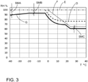
- Figure 3 discloses four curves indicating indoor relative humidity (% RH) values as a function of indoor temperature T. In the disclosed arrangement three damaging phenomena are taken into consideration. A first curve D indicates critical relative humidity values defined for microbial growth, a second curve E indicates critical relative humidity values defined for moisture condensation and a third curve F indicates critical relative humidity values for iron corrosion. Figure 3 further discloses a relative humidity limit curve G which defines relative humidity values below the mentioned three curves D, E and F at different temperatures. The disclosed apparatus A may use values of the curve G as limit values in the control measures at different temperatures.
- the curve G may be defined by determining at first the most critical damaging phenomena for different temperature ranges and requiring the lowest critical relative humidity values. Then, for example, safety margins SMA, SMB, SMC are defined for the RH values based on scientific studies and empirical data. Magnitude of the safety margins may depend on measuring accuracy of conditions, accuracy of the determined critical RH values and critical conditions prevailing close to thermal bridges of an envelope and other indoor cold surfaces.
- a safety margin SMA is increased at cold temperatures because measuring accuracy of relative humidity decreases.
- the safety margin SMA is greater than a safety margin SMB in Figure 3 .
- a safety margin SMC may be minor than for the phenomena microbe growth and moisture condensation if critical relative humidity values are defined more accurately and if measuring accuracy of the conditions is accurate.
- Figure 4 discloses three curves indicating indoor relative humidity values as a function of indoor temperature. In the disclosed arrangement two damaging phenomena are taken into consideration. A first curve D indicates critical relative humidity values defined for microbial growth and a second curve E indicates critical relative humidity values defined for moisture condensation. Figure 4 further discloses a relative humidity limit curve G which defines relative humidity values below the mentioned curves D and E. Safety margins SM define level of the curve G in relation to the curves D and E. The disclosed apparatus A may use values of the curve G as limit values in the control measures at different temperatures.
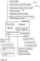
- Figure 5 shows basic components of the control system of the disclosed apparatus.
- a control unit comprising a processor for executing a software program or algorithm.
- the control unit may communicate with different external apparatuses in a versatile manner by means of a data communication device.
- the control unit generates control signals and controls operation of one or more heating devices and/or ventilating devices.
- the control unit may also produce additional signals such as alarms and messages and may also receive and produce needed remote control data.
Landscapes
- Engineering & Computer Science (AREA)
- Chemical & Material Sciences (AREA)
- General Engineering & Computer Science (AREA)
- Mechanical Engineering (AREA)
- Combustion & Propulsion (AREA)
- Physics & Mathematics (AREA)
- Architecture (AREA)
- Signal Processing (AREA)
- Civil Engineering (AREA)
- Mathematical Physics (AREA)
- Fuzzy Systems (AREA)
- General Physics & Mathematics (AREA)
- Electromagnetism (AREA)
- Structural Engineering (AREA)
- Automation & Control Theory (AREA)
- Emergency Management (AREA)
- Business, Economics & Management (AREA)
- Life Sciences & Earth Sciences (AREA)
- Sustainable Development (AREA)
- Air Conditioning Control Device (AREA)
Abstract
An apparatus, method and computer program product for controlling conditions in the indoor space of a built-up shell. The apparatus (A) is configured to sense indoor temperature (TIN) and relative humidity (RHIN) in an inner space (IS) limited by an envelope (BE). The apparatus comprises a control unit (CU) by means of which at least one humidity decreasing device (HDD) is controlled for decreasing level of relative humidity in the inner space. The control unit comprises data on indoor relative humidity limit values at different indoor temperatures and compares the sensed values to the limit values (RHLimit). The limit values include data for preventing two or more indoor damaging phenomena. Control signals are generated on the basis of the comparison between the sensed values and limit values.
Description
- The invention relates to an apparatus configured to control indoor conditions of a built-up shell in order to prevent damages related to high indoor relative humidity level.
- The invention further relates to a method and computer program product for controlling indoor conditions.
- The field of the invention is defined more specifically in the preambles of the independent claims.
- Unsuitable combinations of temperature and relative humidity are risks for microbial growing, moisture condensation and other phenomena possibly causing damages to surfaces located indoor. Risks for damages are increased inside of built-up shell, which are used only temporarily, or heating and ventilation are not set to the level for a typical use. Some arrangements have been designed for the incompletely heated built-up shells. In typical solutions indoor temperature is set to a constant level below a typical operating level. However, these solutions have shown to be inadequate to protect surfaces limiting the indoor space and surfaces of properties located indoor in all cases. Further, energy consumption of the known solutions is often too high.
- An object of the invention is to provide a novel and improved apparatus, method and computer program for controlling indoor conditions of an incompletely heated built-up shell.
- The apparatus according to the invention is characterized by the characterizing features of the first independent apparatus claim.
- The method according to the invention is characterized by the characterizing features of the independent method claim.
- The computer program product according to the invention is characterized by the characterizing features of the second independent apparatus claim.
- An idea of the disclosed solution is that an apparatus is provided for controlling conditions of an incompletely heated built-up shell, which comprises an indoor space limited by an envelope. The apparatus comprises one or more indoor temperature sensors for sensing indoor temperature and one or more indoor humidity sensors for sensing indoor relative humidity inside the built-up shell. The apparatus further comprises one or more control units provided with processors and computer programs executable in the processors. The control unit receives sensing or measuring data from the mentioned sensors and generates control commands for one or more humidity decreasing devices for decreasing level of the relative humidity in the indoor space. Humidity decreasing device can be either a heating device or a ventilating device or consist of both. Further, the control unit comprises data on indoor relative humidity limit values RHLimit which change as a function of the indoor temperature. The mentioned indoor relative humidity limit values RHLimit are based on conditions being favourable for causing damages to surface of objects in the indoor space due to at least two of the following damaging phenomena: microbial growth, moisture condensation, corrosion. The control unit compares the sensed indoor relative humidity values to the indoor relative humidity limit values RHLimit at the sensed indoor temperature. The control unit controls operations of the humidity decreasing device in response to detected fast approach or exceed of the indoor relative humidity limit values RHLimit in order to decrease the indoor relative humidity.
- An advantage of the disclosed solution is that indoor conditions can be monitored in regard several damaging phenomena and at different relative humidity levels and temperatures. This way a comprehensive control system is provided. Further, when risks for adverse phenomena caused by too high level of indoor relative humidity can be effectively decreased, then extensive and expensive repair can be avoided, and further, health problems caused by microbes can be avoided.
- A further advantage of the disclosed solution is that the apparatus is inexpensive and easy to mount and use. There is no need to make any modifications to the built-up shell and its systems and installations. However, solution can also be integrated to heating or automation system of built-up shell.
- Since the disclosed control system is based on the indoor mounted sensors or measuring devices, there is no need to mount sensors and other instrumentation outdoor if ventilating device is not used as a humidity decreasing device. Then the sensors may be integrated to the basic structure of the apparatus, or they may be in wired connection with the apparatus. However, wireless indoor sensing devices for producing sensing or measuring data may also be implemented. Then the sensors may be mounted more freely to desired indoor locations.
- The same apparatus may control one or more compartments of the same built-up shell and may implement the same or somewhat different control principles and parameters in different compartments. Structures, building materials and intended use of the compartments may be different wherefore the control may also differ. Further, two or more separate built-up shells may have one common apparatus for implementing the disclosed control. In other words, the apparatus is capable of managing several different built-up shells and several compartments of the same built-up shell.
- Ventilating device can lower the relative humidity of the indoor air based on two different control principles. If there is no or little heating in the interior and there are envelope or other properties with significant moisture capacity inside, the ventilation control is based on the difference in relative humidity between indoor and outdoor air. If there are no surfaces with significant humidity capacity indoors, the ventilation control is based on the difference in water vapour content between indoor and outdoor air. In both cases, a sensor measuring the outdoor temperature and relative humidity is needed to obtain outdoor data. However, in addition to the outdoor air, the outdoor air sensor can also be located, for example, in a ventilation duct from the outdoor air.
- When the water vapour content of the indoor air is higher than that of the outdoor air, the outdoor air is also typically colder than the indoor air. If air is exchanged in an unheated or slightly heated built-up shell in this case, the indoor space will cool at the same time, which tends to increase the relative humidity inside. Materials with a moisture capacity then adsorb moisture from the indoor air, which increases their moisture content. Wetter materials, in turn, keep the relative humidity of the interior space at a higher level. For this reason, it is advisable to start ventilation in this case when the relative humidity of the indoor air is higher than in the outside air and stop when the relative humidity of the indoor air starts to rise.
- For example, in summer, the relative humidity in indoor air is at its lowest because the temperature is high. The moisture contents of the materials in contact with the indoor air are also at their lowest. As the outside air temperature starts to drop towards winter, it is not advisable to change the air inside the built-up shell, as dry materials keep the indoor relative humidity at a lower level for longer. However, if ventilation in this case were controlled on the basis of the difference in water vapour content, it would be in operation almost all the time because the water vapour content of the indoor air would be higher than that of outdoor air.
- Typically, the control method based on the difference in the relative humidity of the indoor and outdoor air can be used in all kinds of buildings. The control method based on the difference in water vapor content can be used, for example, in caravans, containers and boats.
- In this document the microbial growth includes growth of bacteria and mould as well as growth of other microbes. In other words, moulds and bacteria are microbes which may damage indoor surfaces of the built-up shells and surfaces of other objects in indoor space and may also cause health problems.
- According to an embodiment, the apparatus is designed for fully or partly non-heated built-up shells intended only for occasional or temporary residency or non-residency. In such built-up shells which are incompletely heated, a greater risk for example to microbial growth and moisture condensation occurs compared to built-up shells having stable and relatively high inner temperature. The built-up shell is a summerhouse, summer cottage, holiday home, hut, barrack, warehouse, shed, mobile home, caravan, container, boat or corresponding building or other covered and closed space intended for occasional or temporary residency or non-residency.
- According to an embodiment, the indoor relative humidity limit values RHLimit are based on safety margins defined for at least two critical indoor relative humidity values RHCriticalIn defined for the mentioned at least two damaging phenomena. The safety margins set the indoor relative humidity limit values RHLimit below the critical indoor relative humidity values RHCriticalIn at different indoor temperatures. Purpose of the safety margins is to ensure that indoor conditions does not meet critical relative humidity levels.
- According to an embodiment, the above mentioned safety margins are set 1 - 15 % RH below the critical indoor relative humidity values RHCriticalIn.
- According to an embodiment, the magnitudes of the above mentioned safety margins are configured to change as a function of indoor temperature. In other words, the safety margins are not fixed. The implemented safety margins may be greater at lower temperatures due to inaccuracy of measurements, for example.
- According to an embodiment, the data on indoor relative humidity limit values RHLimit comprise values which are defined on the basis of set safety margins and data on critical indoor relative humidity values RHCriticalInMicrobial defined for conditions being favourable for microbial growth at different indoor temperatures. In other words, adverse indoor conditions in respect to microbial growth are taken into account when controlling level of relative humidity inside the built-up shell.
- According to an embodiment, the above mentioned critical indoor relative humidity value RHCriticalInMicrobial is based on a Finnish Mould Growth Model (FMGM) based on scientific studies on mould growth on surfaces of building materials. The model is designed to determine critical relative humidity values at different temperatures where mould growth occurs. The FMGM model takes into account also time, i.e. how long time favourable mould growth conditions may last without causing problems to the surfaces of objects and cause indoor health problems and damages.
- According to an embodiment, the data on indoor relative humidity limit values RHLimit comprise values based on the set safety margins and data on critical indoor relative humidity values RHCriticalInCondesation for conditions being favourable for moisture condensation at different indoor temperatures. In other words, adverse indoor conditions in respect to moisture condensation are taken into account when controlling level of relative humidity inside the built-up shell.
- According to an embodiment, the data on indoor relative humidity limit values RHLimit comprise values based on the set safety margins and data on critical indoor relative humidity values RHCriticalInCorrosion for conditions being favourable for corrosion at different indoor temperatures. In other words, adverse indoor conditions in respect to iron corrosion, and possibly other corrosions, are taken into account when controlling level of relative humidity inside the built-up shell.
- According to an embodiment, the control unit is provided with at least two separate data sets defining dedicated indoor relative humidity limit values RHLimit for at least two of the mentioned damaging phenomena. The control unit detects at each sensed indoor temperature lowest indoor relative humidity limit values RHLimit of the mentioned separate data sets. Further, the control unit controls the humidity decreasing device in accordance with the detected lowest indoor relative humidity limit values RHLimit of one data set. Thus, the control unit can prioritize the control to provide protection against one damaging phenomena over the other damaging phenomena at each sensed indoor temperature. In other words, the disclosed apparatus may monitor indoor relative humidity values at different temperatures and may select which limit values uses in the executed control measures. The dedicated data sets of different damaging phenomena may in practice comprise functions, algorithms or curves, for example.
- According to an embodiment, the control unit is provided with at least one common data set defining combined indoor relative humidity limit values RHLimit for two or more damaging phenomena. The common data set may comprise for example a function, algorithm or combination curve where combined limit values are considered and presented. This solution is an alternative to above mentioned solution implementing dedicated data sets.
- According to an embodiment, the data on indoor relative humidity limit values RHLimit are input to the control unit. Thus, the apparatus is provided with the limit values which are defined external to the apparatus.
- According to an embodiment, the data on indoor relative humidity limit values RHLimit is calculated in the control unit. Therefore, data on two or more different critical indoor relative humidity values RHCriticalIn defined for the two or more damaging phenomena and different safety margins defined for the different critical indoor relative humidity values RHCriticalIn at different indoor temperatures are input to the control unit. The control unit may execute a computer program or algorithm for calculating the limit values.
- According to an embodiment, the mentioned humidity decreasing device is a heating device. Then the apparatus controls one or more heating devices for increasing indoor temperature.
- According to an embodiment the heating device controlled by means of the disclosed apparatus is an electrical heating device. Alternatively, gas heating, oil heating, pellet heating or any other suitable heating is utilized. However, controlling the electrical heating is simple and accurate. The mentioned other heating systems require control devices for controlling their operation under command of the disclosed apparatus and its control unit.
- According to an embodiment, the mentioned humidity decreasing device is a ventilating device. Then the apparatus controls one or more ventilating devices. In this control additional sensing or measuring data from one or more outdoor temperature sensors and one or more outdoor humidity sensors is needed. The control unit compares the sensing data on indoor relative humidity and outdoor relative humidity as well as sensing data on indoor temperature and outdoor temperature. The control unit may determine indoor and outdoor water vapour content based on the data on sensed indoor and outdoor temperatures and relative humidity values. Further, the control unit controls the ventilating device for starting ventilation when the indoor relative humidity is higher than the outdoor relative humidity and stopping it when the indoor relative humidity begins to rise. This adjustment is performed when materials with significant moisture content are in contact with indoor air. In other cases, the ventilating device starting ventilation when the determined indoor water vapour content is higher than the determined outdoor water vapour content.
- According to an embodiment, the mentioned humidity decreasing device may include also both a heating device and a ventilating device. The heating device and the ventilating device may be separated devices, or the device may be an integrated device. Then the apparatus controls one or more heating devices and one or more ventilating devices at the same time. Heating and ventilation devices are adjusted according to the above principles. The heating device and the ventilating device may be separated devices, or the device may be an integrated device.
- According to an embodiment, the control unit comprises two data sets of indoor relative humidity limit values RHLimit, wherein a first data set define first limit values for conditions being favourable for microbial growth at different indoor temperatures and a second data set define second limit values for conditions being favourable for moisture condensation at different indoor temperatures. The control unit is configured to implement in the control of the humidity decreasing device the mentioned first data set at a first indoor temperature range and the second data set at a second indoor temperature range being below the first temperature range.
- According to an embodiment, the lowest value of the above mentioned first temperature range is 0°C or close to it since almost no microbial growth exists when the temperature is below 0°C.
- According to an embodiment, control measures of the apparatus implement at least two control modes wherein at least one of the control modes is a condensation mode for mitigating moisture condensation on surfaces in the indoor space. Then the control unit comprises indoor relative humidity limit values RHLimit for conditions being favourable for moisture condensation at different indoor temperatures. The control unit comprises an indoor temperature limit value below which the control unit is configured to automatically prioritize the condensation mode over the at least one other control mode and is thereafter configured to control the humidity decreasing device in accordance with the indoor relative humidity limit values RHLimit defined for the condensation mode. In other words, the disclosed condensation mode is a decisive control mode when the indoor temperature is low, and when the indoor temperature is higher, then one or more other control modes are utilized instead.
- According to an embodiment, the above disclosed operation principle may be considered in an opposite way. Then the condensation mode is always on and when operating above the set temperature limit, then the other one, two or even more control modes are utilized since their inner relative humidity limit values RHLimit are at lower lever than the inner relative humidity limit values RHLimit of the condensation mode, whereby they trigger the control measures already at lower relative humidity levels.
- According to an embodiment, the apparatus is provided with several preset alternative settings for the mentioned indoor relative humidity limit values thereby allowing selection of increased safety margins relative to the data on critical indoor relative humidity values RHCriticalIn on which the indoor relative humidity limit values are based on. This control feature allows the indoor relative humidity level to be controlled to lower levels depending on moisture damage phenomena. This way, inner surfaces of the envelope, furniture and any other movable properties in the indoor space can be provided with additional protection, if so desired. Thereby, it is possible to mitigate corrosion, swelling, changes in shapes and dimensions of the objects, and further, emissions of volatile organic compounds (VOC).
- According to an embodiment, the control unit is configured to override the basic control principle based on the indoor relative humidity limit values for a limited maximum period. The disclosed override may be allowed since the microbial growth takes time whereby short term visits in critical conditions may be acceptable.
- According to an embodiment, the above mentioned override may be allowed in order to avoid heating when the energy prize is high.
- According to an embodiment, the mentioned override may be allowed in order to balance energy consumption at peak hours in accordance with a contract with an electric company.
- According to an embodiment, the basic control principles may be overridden when extra energy is available. Then the apparatus may utilize the extra energy, such as solar or wind energy, and may operate the humidity decreasing device, especially a heating device, even when the operation is not necessarily needed in accordance with the basic control principles to prevent the microbial growth or to prevent moisture condensation inside the indoor space.
- According to an embodiment, the apparatus is provided with outdoor sensing data on outdoor temperature and relative humidity for determining outdoor conditions. The control unit is configured to update the control measures at predetermined intervals. And further, the control unit is configured to monitor rate of change in outdoor conditions in response to the received outdoor sensing data and is configured to automatically adjust frequency of the updates of the control in response to the detected rate of change. Thus, when the apparatus notifies that outdoor conditions change rapidly, the apparatus can then react without unnecessary delays. This way, it is possible to decrease problems caused by moisture condensation, for example.
- According to an embodiment, the disclosed solution relates to a method of controlling indoor conditions of an incompletely heated built-up shell comprising an inner space limited by an envelope. The method comprises the following steps: sensing indoor temperature; sensing indoor relative humidity; transmitting sensing data to at least one control unit; and controlling by means of the control unit at least one humidity decreasing device for decreasing level of the relative humidity in the indoor space. The method further comprises: defining indoor relative humidity limit values RHLimit for conditions being favourable for causing damages to surface of objects in the indoor space due to at least two of the following damaging phenomena: microbial growth, moisture condensation, corrosion; comparing the sensed indoor relative humidity values to the indoor relative humidity limit values RHLimit at the sensed indoor temperatures; and controlling the humidity decreasing device in response to detected fast approach or exceed of the indoor relative humidity limit values RHLimit in order to decrease the indoor relative humidity.
- According to an embodiment, the disclosed solution relates to a computer program product. The computer program product comprises program code means configured to execute the steps and procedures disclosed in this document when being run on a computer or a data processing device.
- According to an embodiment, the apparatus and its control unit may communicate with one or more external devices such as computers, smart phones via Internet connection or telecommunication systems, for example. Then it is possible to modify and communicate to the apparatus control status on/off, control parameters, and control set points. In other words, the apparatus may comprise remote control and update features.
- The above disclosed embodiments may be combined in order to form suitable solutions having those of the above features that are needed.
- Some embodiments are described in more detail in the accompanying drawings, in which
-
Figure 1 is a schematic view of a built-up shell, in this case a building provided with an apparatus for controlling indoor humidity, -
Figure 2 is a schematic diagram of damage phenomena caused by high level of relative humidity to surfaces in the indoor space, -
Figure 3 is a schematic graph illustrating control principles implemented by means of the disclosed apparatus for controlling indoor conditions in order to prevent three types of damage phenomena, -
Figure 4 is a schematic graph illustrating control principles implemented by means of the disclosed apparatus when preventing moisture condensation and mould growth, and -
Figure 5 is a schematic diagram of some features relating to a control system of the apparatus. - For the sake of clarity, the figures show some embodiments of the disclosed solution in a simplified manner. In the figures, like reference numerals identify like elements.
-
Figure 1 discloses a built-up shell B, in this case a building provided with an inner space IS limited by an envelope BE which may be at least partly insulated I. The inner space IS may be heated by means of one or more heating devices HD in order to increase indoor temperature TIN. The heating device HD may be an electrically operable device, or it may alternatively be any other kind of heating device. The heating device HD may be controlled by means of a control apparatus A. Further, the built-up shell B may or may not be provided with one or more ventilating devices VD for ventilating the indoor space IS. The ventilating device VD may also be controlled by means of the apparatus A. The heating device HD and the ventilating device VD are both humidity decreasing devices HDD by means of which relative humidity level in the indoor space IS can be decreased. The heating device HD and the ventilating device VD can be operated in combination or separately. - The apparatus A monitors indoor conditions CIN and generates control commands CC for controlling the humidity decreasing devices HDD. The apparatus A is provided with one or more indoor temperature sensors ITS or corresponding measuring devices and one or more indoor relative humidity sensors IHS or corresponding measuring devices for determining the indoor conditions CIN. The indoor conditions CIN are determined on the basis of received indoor temperature TIN and relative humidity RHIN. The apparatus A may also receive sensing data from one or more outdoor temperature sensors OTS and outdoor humidity sensors OHS for special control applications. In the disclosed basic control outdoor measuring data is not required. The sensors ITS, IHS (OTS, OHS) may transmit the sensing data to the apparatus A through wired or wireless data communication paths. The apparatus A may be mounted to the built-up shell B, or alternatively, it may be located external to the built-up shell B. Further, the apparatus A may communicate with one or more external electrical devices via data communication connections. Thus, the apparatus A may communicate with one or more servers S, cloud services CS and portable electrical terminal devices TD, such as smart phones. Thus, the apparatus A may implement external computation and data storage features, and further, control parameters and instructions may be adjusted by means of the external electrical devices. The apparatus A may also provide an operator O with information on status, sensing data, mould growth risk, energy consumption and other issues. The built-up shell B is an incompletely heated piece of real estate, which means that the indoor temperature TIN is allowed to decrease below a typical operating level during the cold seasons. The apparatus A is provided with one or more control units CU for generating the control commands. The control unit CU is configured to execute a computer program product in a processor. The program comprises an algorithm for controlling the humidity decreasing device HDD so that set control principles are achieved. In this solution the control system aims to protect surfaces of the structures and other objects in the indoor space IS, not to be damaged due to too high level of relative humidity and by means of two or more damaging phenomena. However, at the same time, the control system aims to minimize energy consumption of the built-up shell.
-
Figure 2 discloses three adverse phenomenon which may cause serious problems to surfaces and materials in indoor space of the built-up shell. Microbial growth, moisture condensation and corrosion may damage indoor surfaces when indoor condition exceed defined critical levels of relative humidity and temperature. The disclosed apparatus may monitor indoor conditions at defined measuring rate and can control on the basis of the monitoring measures humidity decreasing devices so that indoor conditions remain safe at different temperatures. Thus, two or more damaging phenomena are considered in the control system. Further, the apparatus may also implement one or more additional damaging phenomena and data defined for them in addition to the mentioned three damaging phenomena microbial growth, moisture condensation and corrosion. -
Figure 3 discloses four curves indicating indoor relative humidity (% RH) values as a function of indoor temperature T. In the disclosed arrangement three damaging phenomena are taken into consideration. A first curve D indicates critical relative humidity values defined for microbial growth, a second curve E indicates critical relative humidity values defined for moisture condensation and a third curve F indicates critical relative humidity values for iron corrosion.Figure 3 further discloses a relative humidity limit curve G which defines relative humidity values below the mentioned three curves D, E and F at different temperatures. The disclosed apparatus A may use values of the curve G as limit values in the control measures at different temperatures. - The curve G may be defined by determining at first the most critical damaging phenomena for different temperature ranges and requiring the lowest critical relative humidity values. Then, for example, safety margins SMA, SMB, SMC are defined for the RH values based on scientific studies and empirical data. Magnitude of the safety margins may depend on measuring accuracy of conditions, accuracy of the determined critical RH values and critical conditions prevailing close to thermal bridges of an envelope and other indoor cold surfaces.
- In
Figure 3 a safety margin SMA is increased at cold temperatures because measuring accuracy of relative humidity decreases. Thus, the safety margin SMA is greater than a safety margin SMB inFigure 3 . For iron corrosion phenomena a safety margin SMC may be minor than for the phenomena microbe growth and moisture condensation if critical relative humidity values are defined more accurately and if measuring accuracy of the conditions is accurate. - The control system does not necessarily need to determine the most critical damaging phenomena at a certain order when the indoor temperature changes, as it is shown in
Figure 3 , but instead one of the damaging phenomena may be critical at high temperatures and at somewhat lower temperatures, and between these temperature conditions there may be another more critical damaging phenomenon. -
Figure 4 discloses three curves indicating indoor relative humidity values as a function of indoor temperature. In the disclosed arrangement two damaging phenomena are taken into consideration. A first curve D indicates critical relative humidity values defined for microbial growth and a second curve E indicates critical relative humidity values defined for moisture condensation.Figure 4 further discloses a relative humidity limit curve G which defines relative humidity values below the mentioned curves D and E. Safety margins SM define level of the curve G in relation to the curves D and E. The disclosed apparatus A may use values of the curve G as limit values in the control measures at different temperatures. - In
Figure 4 the curve D is based on Finnish Mould Growth Model. For the curves D and E a constant safety margin is implemented in this example. -
Figure 5 shows basic components of the control system of the disclosed apparatus. By means of an input device sensing data, parameters, limit values, safety margins, temperature settings, and other data and settings may be input for a control unit comprising a processor for executing a software program or algorithm. The control unit may communicate with different external apparatuses in a versatile manner by means of a data communication device. The control unit generates control signals and controls operation of one or more heating devices and/or ventilating devices. The control unit may also produce additional signals such as alarms and messages and may also receive and produce needed remote control data. - The drawings and the related description are only intended to illustrate the idea of the invention. In its details, the invention may vary within the scope of the claims.
Claims (14)
- An apparatus (A) for controlling conditions of an incompletely heated built-up shell (B) and comprising an indoor space (IS) limited by an envelope (BE);
wherein the apparatus (A) comprises:at least one indoor temperature sensor (ITS) for sensing indoor temperature (TIN) in the indoor space (IS);at least one indoor humidity sensor (IHS) for sensing indoor relative humidity (RHIN) in the indoor space (IS);at least one control unit (CU) provided with at least processor and a computer program executable in the processor;and wherein the control unit (CU) is configured to receive sensing data from the mentioned sensors (ITS, IHS) and is configured to generate control commands (CC) for at least one humidity decreasing device (HDD) for decreasing level of the relative humidity inside the indoor space (IS);characterized in thatthe control unit (CU) comprises data on indoor relative humidity limit values (RHLimit) which change as a function of the indoor temperature (TIN), and wherein the indoor relative humidity limit values (RHLimit) are defined for conditions being favourable for causing damages to surfaces of objects in the indoor space (IS) due to at least two of the following damaging phenomena: microbial growth, moisture condensation, corrosion;the control unit (CU) is configured compare the sensed indoor relative humidity values (RHIN) to the indoor relative humidity limit values (RHLimit) at the sensed indoor temperature (TIN), and is configured to operate at least one heating device (HD), which is serving as the mentioned at least one humidity decreasing device (HDD), in response to detected exceed of the indoor relative humidity limit values (RHLimit) in order to decrease the indoor relative humidity (RHIN) by increasing the indoor temperature (TIN) . - The apparatus as claimed in claim 1, characterized in that
the indoor relative humidity limit values (RHLimit) relay on safety margins defined for data on at least two critical indoor relative humidity values (RHCriticalIn) defined for the mentioned at least two damaging phenomena, and wherein the safety margins (SM) set the indoor relative humidity limit values (RHLimit) below the critical indoor relative humidity values (RHCriticalIn) at different indoor temperatures (TIN) . - The apparatus as claimed in claim 2, characterized in that
the safety margins (SM) are set 1 - 15 % RH below the critical indoor relative humidity values (RHcriticalIn) . - The apparatus as claimed in claim 2 or 3, characterized in that
the magnitudes of the safety margins (SM) are configured to change as a function of indoor temperature (TIN). - The apparatus as claimed in any one of the preceding claims 1 - 4, characterized in that
the data on indoor relative humidity limit values (RHLimit) comprise values based on the set safety margins (SM) and data on critical indoor relative humidity values (RHcriticalInMicrobial) defined for conditions being favourable for microbial growth at different indoor temperatures (TIN). - The apparatus as claimed in any one of the preceding claims 1 - 5, characterized in that
the data on indoor relative humidity limit values (RHLimit) comprise values based on the set safety margins (SM) and data on critical indoor relative humidity values (RHCriticalInCondesation) for conditions being favourable for moisture condensation at different indoor temperatures (TIN) . - The apparatus as claimed in any one of the preceding claims 1 - 6, characterized in that
the data on indoor relative humidity limit values (RHLimit) comprise values based on the set safety margins (SM) and data on critical indoor relative humidity values (RHcriticalIncorrosion) for conditions being favourable for corrosion at different indoor temperatures (TIN). - The apparatus as claimed in any one of the preceding claims 1 - 7, characterized in thatthe control unit (CU) is provided with at least two separate data sets defining dedicated indoor relative humidity limit values (RHLimit) for at least two of the mentioned damaging phenomena;the control unit (CU) is configured detect at each sensed indoor temperature (TIN) lowest indoor relative humidity limit values (RHLimit) of the separate data sets; andthe control unit (CU) is configured to control the humidity decreasing device (HDD) in accordance with the detected lowest indoor relative humidity limit values (RHLimit) of one data set whereby the control unit (CU) is configured to prioritize the control to provide protection against one damaging phenomena over the other damaging phenomena at each sensed indoor temperature (TIN).
- The apparatus as claimed in any one of the preceding claims 1 - 7, characterized in that
the control unit (CU) is provided with at least one common data set defining combined indoor relative humidity limit values (RHLimit) for at least two of the mentioned damaging phenomena. - The apparatus as claimed in any one of the preceding claims 1 - 9, characterized in that
the apparatus comprises an input device for inputting the data on indoor relative humidity limit values (RHLimit) to the control unit (CU) . - The apparatus as claimed in any one of the preceding claims 1 - 9, characterized in that
the data on indoor relative humidity limit values (RHLimit) is calculated in the control unit (CU) in response to input data on at least two different critical indoor relative humidity values (RHCriticalIn) defined for the mentioned at least two damaging phenomena, and input different safety margins (SM) defined for the different critical indoor relative humidity values (RHCriticalIn) at different indoor temperatures (TIN). - The apparatus as claimed in any one of the preceding claims 1 - 11, characterized in thatthe apparatus (A) is configured to further control at least one ventilating device (VD), which is serving as an additional humidity decreasing device (HDD);the apparatus (A) further comprises at least one outdoor temperature sensor (OTS) and at least one outdoor humidity sensor (OHS);the control unit (CU) is configured to compare sensing data on indoor relative humidity (RHIN) and outdoor relative humidity (RHOUT) as well as sensing data on indoor temperature (TIN) and outdoor temperature (TOUT); andthe control unit (CU) is configured to control the ventilating device (VD) for start ventilating the indoor space (IS) when the indoor relative humidity is higher than the outdoor relative humidity and stop ventilating when the indoor relative humidity begins to rise.
- A method of controlling indoor conditions (CIN) of an incompletely heated built-up shell (B) comprising an inner space (IS) limited by an envelope (BE),
wherein the method comprises:sensing indoor temperature (TIN);sensing indoor relative humidity (RHIN);transmitting sensing data to at least one control unit (CU); andcontrolling by means of the control unit (CU) at least one humidity decreasing device (HDD) for decreasing level of the relative humidity (RHIN) in the indoor space (IS) ;characteri zed byproviding the control unit (CU) with indoor relative humidity limit values (RHLimit)for conditions being favourable for causing damages to surfaces of objects in the indoor space (IS) due to at least two of the following damaging phenomena: microbial growth, moisture condensation, corrosion;comparing the sensed indoor relative humidity values (RHIN) to the indoor relative humidity limit values (RHLimit) at the sensed indoor temperatures (TIN) ; andcontrolling at least one heating device (HD), which is serving as the humidity decreasing device (HDD), in response to detected exceed of the indoor relative humidity limit values (RHLimit) in order to decrease the indoor relative humidity (RHIN) by heating the inner space (IS) . - A computer program product for controlling indoor conditions (CIN) of an incompletely heated built-up shell (B) comprising an inner space (IS) limited by an envelope,
where the computer program product comprises program code means configured to execute the following steps when being run on a computer or a data processing device:receiving sensed indoor temperature (TIN) and sensed indoor relative humidity data (RHIN);controlling at least one humidity decreasing device (HDD) for decreasing level of the relative humidity (RHIN) in the indoor space (IS);characterized incomparing the sensed indoor relative humidity values (RHIN) to indoor relative humidity limit values (RHLimit) at the sensed indoor temperatures (TIn), where the indoor relative humidity limit values (RHLimit) are defined for conditions being favourable for causing damages to surfaces of objects in the indoor space (IS) due to at least two of the following damaging phenomena: microbial growth, moisture condensation, corrosion; andcontrolling at least one heating device (HD), which is serving as the humidity decreasing device (HDD), in response to detected exceed of the indoor relative humidity limit values (RHLimit) in order to decrease the indoor relative humidity (RHIn) by heating the inner space (IS) .
Applications Claiming Priority (1)
| Application Number | Priority Date | Filing Date | Title |
|---|---|---|---|
| FI20205849A FI129390B (en) | 2020-09-01 | 2020-09-01 | Apparatus, method and computer program product for controlling indoor conditions |
Publications (1)
| Publication Number | Publication Date |
|---|---|
| EP3961117A1 true EP3961117A1 (en) | 2022-03-02 |
Family
ID=77864313
Family Applications (1)
| Application Number | Title | Priority Date | Filing Date |
|---|---|---|---|
| EP21194005.1A Withdrawn EP3961117A1 (en) | 2020-09-01 | 2021-08-31 | Apparatus, method and computer program product for controlling indoor conditions |
Country Status (3)
| Country | Link |
|---|---|
| EP (1) | EP3961117A1 (en) |
| CA (1) | CA3129344A1 (en) |
| FI (1) | FI129390B (en) |
Cited By (2)
| Publication number | Priority date | Publication date | Assignee | Title |
|---|---|---|---|---|
| EP4425063A1 (en) | 2023-03-03 | 2024-09-04 | Schwab Technik GmbH | Method of ventilation and ventilation device |
| CN119468407A (en) * | 2024-12-11 | 2025-02-18 | 珠海格力电器股份有限公司 | Wire controller temperature detection fault scheduling method, wire controller, device and storage medium |
Citations (7)
| Publication number | Priority date | Publication date | Assignee | Title |
|---|---|---|---|---|
| JPH05126385A (en) * | 1991-11-08 | 1993-05-21 | Matsushita Seiko Co Ltd | Antifungal device |
| WO2008039149A1 (en) * | 2006-09-29 | 2008-04-03 | Lindenstone Innovation Ab | Device to protect a space from damage caused by damp or moisture |
| DE102010055065A1 (en) * | 2010-12-17 | 2012-06-21 | Renate Seifarth | Ventilation device for e.g. automatic ventilation of cellar room in home, has control unit comprising communication links to drive, indoor humidity and temperature sensors, outdoor humidity and temperature sensors and wall humidity sensor |
| US20130040550A1 (en) * | 2010-04-29 | 2013-02-14 | Dryvent Solutions Of Scandinavia Ab | System and method for ventilating a defined space |
| US20180163983A1 (en) * | 2016-12-13 | 2018-06-14 | Lg Electronics Inc. | Bathroom management system |
| US20190078805A1 (en) * | 2013-03-15 | 2019-03-14 | Delta T, Llc | Condensation control system and related method |
| WO2020100176A1 (en) * | 2018-11-13 | 2020-05-22 | De' Longhi Appliances S.R.L. Con Unico Socio | Method of controlling an air-conditioning system |
-
2020
- 2020-09-01 FI FI20205849A patent/FI129390B/en active IP Right Grant
-
2021
- 2021-08-30 CA CA3129344A patent/CA3129344A1/en active Pending
- 2021-08-31 EP EP21194005.1A patent/EP3961117A1/en not_active Withdrawn
Patent Citations (7)
| Publication number | Priority date | Publication date | Assignee | Title |
|---|---|---|---|---|
| JPH05126385A (en) * | 1991-11-08 | 1993-05-21 | Matsushita Seiko Co Ltd | Antifungal device |
| WO2008039149A1 (en) * | 2006-09-29 | 2008-04-03 | Lindenstone Innovation Ab | Device to protect a space from damage caused by damp or moisture |
| US20130040550A1 (en) * | 2010-04-29 | 2013-02-14 | Dryvent Solutions Of Scandinavia Ab | System and method for ventilating a defined space |
| DE102010055065A1 (en) * | 2010-12-17 | 2012-06-21 | Renate Seifarth | Ventilation device for e.g. automatic ventilation of cellar room in home, has control unit comprising communication links to drive, indoor humidity and temperature sensors, outdoor humidity and temperature sensors and wall humidity sensor |
| US20190078805A1 (en) * | 2013-03-15 | 2019-03-14 | Delta T, Llc | Condensation control system and related method |
| US20180163983A1 (en) * | 2016-12-13 | 2018-06-14 | Lg Electronics Inc. | Bathroom management system |
| WO2020100176A1 (en) * | 2018-11-13 | 2020-05-22 | De' Longhi Appliances S.R.L. Con Unico Socio | Method of controlling an air-conditioning system |
Cited By (2)
| Publication number | Priority date | Publication date | Assignee | Title |
|---|---|---|---|---|
| EP4425063A1 (en) | 2023-03-03 | 2024-09-04 | Schwab Technik GmbH | Method of ventilation and ventilation device |
| CN119468407A (en) * | 2024-12-11 | 2025-02-18 | 珠海格力电器股份有限公司 | Wire controller temperature detection fault scheduling method, wire controller, device and storage medium |
Also Published As
| Publication number | Publication date |
|---|---|
| FI129390B (en) | 2022-01-31 |
| CA3129344A1 (en) | 2022-03-01 |
| FI20205849A1 (en) | 2022-01-31 |
Similar Documents
| Publication | Publication Date | Title |
|---|---|---|
| CN113324325B (en) | Accurate temperature control method and device of air conditioner and air conditioner | |
| US11598344B2 (en) | Automatic control system for ceiling fan based on temperature differentials | |
| EP2985563B1 (en) | Device for controlling cooling system | |
| CN104406251B (en) | Air conditioner dehumanization method and air conditioner | |
| CN109323398B (en) | Air conditioner control method, device and air conditioner | |
| US20130128455A1 (en) | Environmental control for module housing electronic equipment racks | |
| CN111124013B (en) | Climate box environment adjusting method and device and computer storage medium | |
| US10267529B2 (en) | System and method for dynamically controlling economizers | |
| US20150204594A1 (en) | Air condition system, method for controlling air condition system, and outdoor apparatus of air condition system | |
| US20180180302A1 (en) | System and method for balancing temperature within a building | |
| CN115059992A (en) | Control method of air conditioner, controller, air conditioner and storage medium | |
| WO2024093391A1 (en) | Control method and apparatus for indoor unit of wall-mounted air conditioner, and indoor unit of wall-mounted air conditioner | |
| FI129390B (en) | Apparatus, method and computer program product for controlling indoor conditions | |
| JP7140702B2 (en) | Environmental control system for agricultural greenhouses, greenhouse control equipment | |
| FI129397B (en) | Apparatus, method and computer program product for controlling conditions in a building | |
| US20140182313A1 (en) | Process control of temperature and humidity for electrical appliances | |
| CN114963467B (en) | Air conditioner heating control method and device, electronic equipment and storage medium | |
| JP2013185768A (en) | Air conditioning control device and air conditioning control method | |
| CN115523633B (en) | Air conditioner control method, air conditioner and computer readable storage medium | |
| US10788233B2 (en) | Dynamic HVAC machine room setpoint computation | |
| US20160216718A1 (en) | System and method for limiting hvac motor torque | |
| US10724753B2 (en) | System and method for operating a variable speed compressor | |
| WO2024093390A1 (en) | Control method and device for wall-mounted indoor air-conditioning unit, and wall-mounted indoor air-conditioning unit | |
| CN116164391A (en) | Air conditioner and condensation prevention control method thereof | |
| CN107726570A (en) | The control method of air lock aperture, device and storage medium in air handling system |
Legal Events
| Date | Code | Title | Description |
|---|---|---|---|
| PUAI | Public reference made under article 153(3) epc to a published international application that has entered the european phase |
Free format text: ORIGINAL CODE: 0009012 |
|
| STAA | Information on the status of an ep patent application or granted ep patent |
Free format text: STATUS: THE APPLICATION HAS BEEN PUBLISHED |
|
| AK | Designated contracting states |
Kind code of ref document: A1 Designated state(s): AL AT BE BG CH CY CZ DE DK EE ES FI FR GB GR HR HU IE IS IT LI LT LU LV MC MK MT NL NO PL PT RO RS SE SI SK SM TR |
|
| STAA | Information on the status of an ep patent application or granted ep patent |
Free format text: STATUS: THE APPLICATION IS DEEMED TO BE WITHDRAWN |
|
| 18D | Application deemed to be withdrawn |
Effective date: 20220903 |