EP3961022A1 - Internal combustion engine - Google Patents
Internal combustion engine Download PDFInfo
- Publication number
- EP3961022A1 EP3961022A1 EP21190855.3A EP21190855A EP3961022A1 EP 3961022 A1 EP3961022 A1 EP 3961022A1 EP 21190855 A EP21190855 A EP 21190855A EP 3961022 A1 EP3961022 A1 EP 3961022A1
- Authority
- EP
- European Patent Office
- Prior art keywords
- intake
- intake port
- port
- valve
- recesses
- Prior art date
- Legal status (The legal status is an assumption and is not a legal conclusion. Google has not performed a legal analysis and makes no representation as to the accuracy of the status listed.)
- Granted
Links
Images


Classifications
-
- F—MECHANICAL ENGINEERING; LIGHTING; HEATING; WEAPONS; BLASTING
- F01—MACHINES OR ENGINES IN GENERAL; ENGINE PLANTS IN GENERAL; STEAM ENGINES
- F01L—CYCLICALLY OPERATING VALVES FOR MACHINES OR ENGINES
- F01L3/00—Lift-valve, i.e. cut-off apparatus with closure members having at least a component of their opening and closing motion perpendicular to the closing faces; Parts or accessories thereof
- F01L3/06—Valve members or valve-seats with means for guiding or deflecting the medium controlled thereby, e.g. producing a rotary motion of the drawn-in cylinder charge
-
- F—MECHANICAL ENGINEERING; LIGHTING; HEATING; WEAPONS; BLASTING
- F02—COMBUSTION ENGINES; HOT-GAS OR COMBUSTION-PRODUCT ENGINE PLANTS
- F02F—CYLINDERS, PISTONS OR CASINGS, FOR COMBUSTION ENGINES; ARRANGEMENTS OF SEALINGS IN COMBUSTION ENGINES
- F02F1/00—Cylinders; Cylinder heads
- F02F1/24—Cylinder heads
- F02F1/42—Shape or arrangement of intake or exhaust channels in cylinder heads
- F02F1/4235—Shape or arrangement of intake or exhaust channels in cylinder heads of intake channels
-
- F—MECHANICAL ENGINEERING; LIGHTING; HEATING; WEAPONS; BLASTING
- F01—MACHINES OR ENGINES IN GENERAL; ENGINE PLANTS IN GENERAL; STEAM ENGINES
- F01L—CYCLICALLY OPERATING VALVES FOR MACHINES OR ENGINES
- F01L3/00—Lift-valve, i.e. cut-off apparatus with closure members having at least a component of their opening and closing motion perpendicular to the closing faces; Parts or accessories thereof
- F01L3/08—Valves guides; Sealing of valve stem, e.g. sealing by lubricant
-
- F—MECHANICAL ENGINEERING; LIGHTING; HEATING; WEAPONS; BLASTING
- F02—COMBUSTION ENGINES; HOT-GAS OR COMBUSTION-PRODUCT ENGINE PLANTS
- F02B—INTERNAL-COMBUSTION PISTON ENGINES; COMBUSTION ENGINES IN GENERAL
- F02B2275/00—Other engines, components or details, not provided for in other groups of this subclass
- F02B2275/48—Tumble motion in gas movement in cylinder
-
- Y—GENERAL TAGGING OF NEW TECHNOLOGICAL DEVELOPMENTS; GENERAL TAGGING OF CROSS-SECTIONAL TECHNOLOGIES SPANNING OVER SEVERAL SECTIONS OF THE IPC; TECHNICAL SUBJECTS COVERED BY FORMER USPC CROSS-REFERENCE ART COLLECTIONS [XRACs] AND DIGESTS
- Y02—TECHNOLOGIES OR APPLICATIONS FOR MITIGATION OR ADAPTATION AGAINST CLIMATE CHANGE
- Y02T—CLIMATE CHANGE MITIGATION TECHNOLOGIES RELATED TO TRANSPORTATION
- Y02T10/00—Road transport of goods or passengers
- Y02T10/10—Internal combustion engine [ICE] based vehicles
- Y02T10/12—Improving ICE efficiencies
Definitions
- the present invention generally relates to an internal combustion engine.
- Japanese Patent First Publication No. 2018-141433 discloses such a type of internal combustion engine which has an edge formed in the shape of a line on a downstream end of an intake port floor near an intake opening exposed to a combustion chamber for departing a flow of intake air from an inner wall of the intake port.
- the edge works to orient the flow of intake air, as departing from the inner wall of the intake port, to where tumbles flows are generated, thereby minimizing a risk that tumble flows may be generated in the reverse direction and also enhancing the tumble flows in the forward direction.
- the above described engine has the line-shaped edge extending continuously over a wide region, thereby causing most of the flow of intake air departing from the edge to advance straight in a direction in which the intake port extends without spreading over a circumference of an edge of the intake opening.
- This causes an effective sectional area of a flow path of the intake port downstream of the edge to be smaller than an area of the intake opening, which leads to a reduction in amount of intake air delivered into the combustion chamber.
- the invention was made in view of the above problems. It is an object of the invention to provide an internal combustion engine designed to ensure the stability in creating a tumble flow of intake air in a combustion chamber and enhance the efficiency in delivering the intake air into the combustion chamber.
- an internal combustion engine which comprises: (a) a cylinder head which includes an intake opening which is exposed to a combustion chamber and an intake port which extends toward the intake opening and communicates with the intake opening; (b) an intake valve which works to open or close the intake opening; and (c) a circular valve seat which has a valve resting surface on which the intake valve rests and is fit in the intake opening.
- the intake port has a downstream intake port surface defined by a surface of a wall of a downstream end of the intake port close to the combustion chamber.
- the valve seat includes a port connection surface and an edge. The port connection surface connects between the downstream intake port surface and the valve resting surface and intersects with the downstream intake port surface.
- the edge defines a line-shaped sharp corner on an intersection between the downstream intake port surface and the port connection surface.
- a plurality of recesses are arranged adjacent each other in a circumferential direction of the intake port. The recesses extend in a direction in which the intake port extends and are hollowed in the downstream intake port surface and the port connection surface to increase a transverse sectional area of the intake opening.
- An internal combustion engine comprises: (a) a cylinder head which includes an intake opening which is exposed to a combustion chamber and an intake port which extends toward the intake opening and communicates with the intake opening; (b) an intake valve which works to open or close the intake opening; and (c) a circular valve seat which has a valve resting surface on which the intake valve rests and is fit in the intake opening.
- the intake port has a downstream intake port surface defined by a surface of a wall of a downstream end of the intake port close to the combustion chamber.
- the valve seat includes a port connection surface and an edge. The port connection surface connects between the downstream intake port surface and the valve resting surface and intersects with the downstream intake port surface.
- the edge defines a line-shaped sharp corner on an intersection between the downstream intake port surface and the port connection surface.
- a plurality of recesses are arranged adjacent each other in a circumferential direction of the intake port.
- the recesses extend in a direction in which the intake port extends and are hollowed in the downstream intake port surface and the port connection surface to increase a transverse sectional area of the intake opening.
- a vertical, a longitudinal, and a lateral direction correspond to a vertical, a longitudinal, and a lateral direction of the internal combustion engine mounted in a vehicle.
- the lateral direction is perpendicular to the longitudinal direction of the vehicle.
- a height direction of the internal combustion engine agrees with the vertical direction.
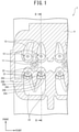
- Fig. 1 to 5 are views which illustrates the internal combustion engine according to the embodiment of the invention.
- the internal combustion engine 1 includes the cylinder block 2 in which the cylinders 3 are formed and the cylinder head 4 which defines the combustion chambers 5 therein.
- the cylinder head 4 is joined to an upper portion of the cylinder block 2.
- the internal combustion engine 1 is designed as a multi-cylinder engine equipped with the plurality of cylinders 3 formed in the cylinder block 2.
- the internal combustion engine 1 works to achieve combustion of fuel and air (which will also be referred to below as intake air) sucked from the outside within each of the combustion chambers 5 to produce kinetic energy.
- the cylinder head 4 has formed therein two intake openings 21 exposed to each of the combustion chamber 5 and two exhaust openings 11 exposed to each of the combustion chamber 5.
- the cylinder head 4 has installed therein two intake valves 22 and two exhaust valves 12 for each of the cylinders 3.
- the intake openings 21 open or close the intake openings 21.
- the exhaust valves 12 open or close the exhaust openings 11.
- the intake valves 22 and the exhaust valves 12 are moved simultaneously with rotation of a crankshaft (not shown).
- Each of the intake valves 22 includes the umbrella-shaped valve head 22A which opens or closes a corresponding one of the intake openings 21 and the valve stem 22B which is of the shape of a shaft and supports the valve head 22A.
- the cylinder head 4 has formed therein two intake ports 23 and two exhaust ports 23 for each of the cylinders 3.
- the intake ports 23 supply the intake air to a corresponding one of the combustion chambers 5 through the intake openings 21.
- the exhaust ports 13 discharge exhaust gas from a corresponding one of the combustion chambers 5 through the exhaust openings 11.
- the intake ports 23 leads to a single upstream intake path. Specifically, the upstream intake path extends frontward to the intake opening 21 and is branched into the two intake ports 23 within the cylinder head 4 communicating with the intake openings 21.
- the exhaust ports 13 extend backward to an exhaust outlet, not shown, and are converged into one exhaust path communicating with the exhaust outlet.
- the intake ports 23 extend toward an inner peripheral surface of the cylinder 3 facing the intake openings 21. This causes, when the intake valves 22 are opened, the intake air, as delivered from the intake ports 23 into the combustion chamber 5, to collide with the inner peripheral surface of the cylinder 3 facing the intake openings 21 and an upper surface of a piston, not shown, thereby creating the tumble flow 40 which, as illustrated in Fig. 2 , circulates vertically within the cylinder 3.
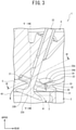
- the internal combustion engine 1 is, as illustrated in Fig. 3 , equipped with the circular valve seats 30.
- the valve seats 30 are fit in the intake openings 21.
- the valve seats 30 are mounted on inner walls of the intake openings 21.
- Each of the valve seats 30 has the valve resting surface 31 on which the intake valve 22 rests.
- Each of the intake ports 23 has the downstream intake port surface 24.
- the downstream intake port surface 24 is defined by a surface of a wall of a downstream end of the intake port 23 near the combustion chamber 5, in other words, a lower surface of the intake ports 23.
- Each of the valve seats 30 includes the port connection surface 32 and the edge 33.
- the port connection surface 32 communicates between the downstream intake port surface 24 and the valve resting surface 31 and is oriented to intersect with the downstream intake port surface 24.
- the edge 33 defines a line-shaped sharp corner on the intersection between the downstream intake port surface 24 and the port connection surface 32.
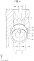
- Each of the intake ports 23 of the cylinder head 4, as illustrated in Figs. 4 and 5 has a plurality of (three in this embodiment) recesses 25A, 25B, and 25C formed in the wall thereof.
- the recesses 25A, 25B, and 25C extend in a direction in which the intake port 23 extends.
- the recesses 25A, 25B, and 25C are each formed to have a depth so as to widen the downstream intake port surface 24 and the port connection surface 32.
- each of the recesses 25A, 25B, and 25C is hollowed both in the downstream intake port surface 24 and in the port connection surface 32 to increase a transverse sectional area of the intake port 23 toward the intake opening 21.
- the recesses 25A, 25B, and 25C are arranged adjacent each other in a circumferential direction of the intake port 23.
- Each of the recesses 25A, 25B, and 25C is shaped to conform with a portion of an outer peripheral surface of a cylinder and may be formed using cutting techniques.
- the recesses 25A, 25B, and 25C are arranged in direct abutment or contact with each other in the circumferential direction, but however, may alternatively be located away from each other in the circumferential direction of the intake port 23.
- the recess 25B that lies at the middle of the recesses 25A, 25B, and 25C in the circumferential direction of the intake port 23 is, as clearly illustrated in Fig. 4 , located to face the valve stem 23B of the intake valve 22 in the direction in which the intake port 23 extends. This causes the flow of intake air moving along the recess 25B to collide with the valve stem 22B of the intake valve 22 so that it is oriented downward and then delivered into the combustion chamber 5.
- the recesses 25A and 25C located on outer opposite sides of the recess 25B are located not to face the valve stem 22B of the intake valve 22 in the direction in which the intake port 23 extends.
- at least one of the recesses 25A, 25B, and 25C is oriented out of alignment with the valve stem 22B of the intake valve 22 in the direction in which the intake port 23 extends.
- the recesses 25A and 25C are located not to overlap with the valve stem 22B of the intake valve 22 in a direction in which the intake air flows in the intake port 23.
- the recess 25B which is located on the middle of the array of the recesses 25A, 25B, and 25C in the circumferential direction of the intake port 23 extends to the valve stem 22B of the intake valve 22 in the direction in which the intake port 23 extends.
- Each of the recesses 25A and 25C which is located outside the recess 25B in the circumferential direction of the intake port 23 extends at an inclined angle to the direction in which the intake port 23 extends so that it departs from the valve stem 22B of the intake valve 22 in the circumferential direction of the intake port 23 as approaching the intake valve 22 in the direction in which the intake port 23 extends.
- the recess 25A is inclined, i.e., extends along a line which passes by the valve stem 22B, in other words, extends away to the left from the valve stem 22B in the circumferential direction of the intake port 23, as viewed in Fig. 4 .
- the recess 25C is inclined, i.e., extends along a line which passes by the valve stem 22B, in other words, extends away to the right from the valve stem 22B in the circumferential direction of the intake port 23, as viewed in Fig. 4 .
- the directions 27A and 27C in which the outer recesses 25A and 25C extend are, therefore, each inclined at a given angle 26 to the direction 27B in which the center recess 25B extends.
- At least one of the recesses 25A, 25B, and 25C is inclined to the direction in which the intake port 23 extends so that it extends out of alignment with the valve stem 22B of the intake valve 22, in other words, it is oriented along a line which is offset in the circumferential direction of the intake port 23 from a line passing through the axial center of the valve stem 22B in the direction in which the intake port 23 extends (i.e., the direction 27B).
- the intake air as sucked from outside the internal combustion engine 1 into the intake port 23 during the intake stroke in the internal combustion engine 1, passes through the intake opening 21 and then enters the combustion chamber 5.
- the intake air then impacts the inner peripheral surface of the cylinder 3 and the upper surface of the piston (not shown), thereby creating the tumble flow 40 which circulates vertically within the cylinder 3.
- each of the valve seats 30 communicates between the downstream intake port surface 24 and the valve resting surface 31 and also has the port connection surface 32 which intersects the downstream intake port surface 24.
- Each of the valve seats 30 has the edge 33 which defines a line-shaped sharp corner lying at the intersection between the downstream intake port surface 24 and the port connection surface 32.
- the intake air flowing on the downstream intake port surface 24 is departed at the edge 33 and then advances in the direction in which the intake port 23 extends to produce an air flow which will enter the combustion chamber 5 and create the tumble flow 40 oriented in the forward direction. This ensures the stability in generating the tumble flow 40 using the intake air within the combustion chamber 5.
- the internal combustion engine 1 in this embodiment also includes the recesses 25A, 25B, and 25C each of which has a length extending in the direction in which the intake port 23 extends and is hollowed in the downstream intake port surface 24 and the port connection surface 32 to increase a transverse sectional area of the intake opening 21.
- the recesses 25A, 25B, and 25C are arranged adjacent each other in the circumferential direction of the intake port 23.
- the edge 33 is lowered in height or level in each of the recesses 25A, 25B, and 25C from the levels of the downstream intake port surface 24 and the port connection surface 32, thereby increasing an area of a portion of the intake opening 21 communicating with the downstream intake port surface 24. This results in an increase in amount of air inducted into the combustion chamber 5 to enhance the efficiency in delivering the air into the combustion chamber 5.
- the plurality of recesses 25A, 25B, and 25C are arranged adjacent each other in the circumferential direction of each of the intake ports 23, thereby also increasing the area of the portion of the intake opening 21 communicating with the downstream intake port surface 24. This also increase the amount of air delivered into the combustion chamber 5 and improves the efficiency in supplying the air into the combustion chamber 5.
- the edge 33 has portions where the recesses 25A, 25B, and 25C exist. Each of such portions has a sharp corner lowered in level from the rest of the edge 33. In other words, after the recesses 25A, 25B, and 25C are formed, the edge 33 still has the sharp lower portions and thus works to minimize a risk that the tumble flow 41 which is oriented in the reverse direction may be generated, thereby ensuring the stability in creating the tumble flow 40 circulating in the forward direction.
- the above arrangements ensure the stability in keeping the tumble flow 40 of the intake air within the combustion chamber 5, thereby improving the efficiency in delivery of the intake air into the combustion chamber 5.
- At least one of the recesses 25A, 25B, and 25C, i.e., the recess 25A or 25B is arranged out of alignment with the valve stem 22B of the intake valve 22 in the direction in which the intake port 23 extends.
- At least one of the recesses 25A, 25B, and 25C i.e., the recess 25A or 25B is oriented to have the longitudinal center line which is inclined at a given angle (excluding zero) to the longitudinal center line of the recess 25B extending through the axial center of the valve stem 22B.
- the longitudinal center line of at least one of the recesses 25A and 25B is inclined relative to the direction in which the intake port 23 extends and arranged away from the valve stem 22B in the radial direction of the intake port 23 (i.e., the intake valve 22).
- the above layout causes the intake air guided by at least one of the recesses 25A and 25C to bypass the valve stem 22B of the intake valve 22, thereby eliminating a risk that the intake air may collide with the valve stem 22B of the intake valve 22, so that it may be turned downward to create the tumble flow 41 in the reverse direction.
- This ensures the stability in creating the tumble flow 40 in the forward direction to increase the amount of intake air delivered into the combustion chamber 5, thereby enhancing the efficiency in supplying the intake air to the combustion chamber 5.
Landscapes
- Engineering & Computer Science (AREA)
- Mechanical Engineering (AREA)
- General Engineering & Computer Science (AREA)
- Chemical & Material Sciences (AREA)
- Combustion & Propulsion (AREA)
- Cylinder Crankcases Of Internal Combustion Engines (AREA)
- Combustion Methods Of Internal-Combustion Engines (AREA)
Abstract
Description
- The present invention generally relates to an internal combustion engine.
- There are internal combustion engines engineered to generate tumble flows in the cylinder in order to improve the combustion of fuel.
Japanese Patent First Publication No. 2018-141433 - The above described engine has the line-shaped edge extending continuously over a wide region, thereby causing most of the flow of intake air departing from the edge to advance straight in a direction in which the intake port extends without spreading over a circumference of an edge of the intake opening. This causes an effective sectional area of a flow path of the intake port downstream of the edge to be smaller than an area of the intake opening, which leads to a reduction in amount of intake air delivered into the combustion chamber.
- The invention was made in view of the above problems. It is an object of the invention to provide an internal combustion engine designed to ensure the stability in creating a tumble flow of intake air in a combustion chamber and enhance the efficiency in delivering the intake air into the combustion chamber.
- According to one aspect of the invention, there is provided an internal combustion engine which comprises: (a) a cylinder head which includes an intake opening which is exposed to a combustion chamber and an intake port which extends toward the intake opening and communicates with the intake opening; (b) an intake valve which works to open or close the intake opening; and (c) a circular valve seat which has a valve resting surface on which the intake valve rests and is fit in the intake opening. The intake port has a downstream intake port surface defined by a surface of a wall of a downstream end of the intake port close to the combustion chamber. The valve seat includes a port connection surface and an edge. The port connection surface connects between the downstream intake port surface and the valve resting surface and intersects with the downstream intake port surface. The edge defines a line-shaped sharp corner on an intersection between the downstream intake port surface and the port connection surface. A plurality of recesses are arranged adjacent each other in a circumferential direction of the intake port. The recesses extend in a direction in which the intake port extends and are hollowed in the downstream intake port surface and the port connection surface to increase a transverse sectional area of the intake opening.
- According to the above invention, it is possible to ensure the stability in creating a tumble flow of intake air in a combustion chamber and improve the efficiency in delivering the intake air into the combustion chamber.
-
-
Fig. 1 is a sectional view, as taken along the line I-I inFig. 2 , which illustrates a cross section of a cylinder head of an internal combustion engine according to an embodiment of the invention. -
Fig. 2 is a sectional view, as taken along the line II-II inFig. 2 , which illustrates the internal combustion engine inFig. 1 . -
Fig. 3 is an enlarged view which illustrates a region around an intake valve of the internal combustion engine inFig. 2 . -
Fig. 4 is a sectional view, as taken along the line IV-IV inFig. 3 , which illustrates the internal combustion engine inFig. 3 . -
Fig. 5 is a sectional view, as taken along the line V-V inFig. 3 , which illustrates the internal combustion engine inFig. 3 . - An internal combustion engine according to an embodiment of the invention comprises: (a) a cylinder head which includes an intake opening which is exposed to a combustion chamber and an intake port which extends toward the intake opening and communicates with the intake opening; (b) an intake valve which works to open or close the intake opening; and (c) a circular valve seat which has a valve resting surface on which the intake valve rests and is fit in the intake opening. The intake port has a downstream intake port surface defined by a surface of a wall of a downstream end of the intake port close to the combustion chamber. The valve seat includes a port connection surface and an edge. The port connection surface connects between the downstream intake port surface and the valve resting surface and intersects with the downstream intake port surface. The edge defines a line-shaped sharp corner on an intersection between the downstream intake port surface and the port connection surface. A plurality of recesses are arranged adjacent each other in a circumferential direction of the intake port. The recesses extend in a direction in which the intake port extends and are hollowed in the downstream intake port surface and the port connection surface to increase a transverse sectional area of the intake opening. The internal combustion engine, therefore, works to ensure the stability in creating a tumble flow of intake air in the combustion chamber and enhance the efficiency in delivering the intake air into the combustion chamber.
- An internal combustion engine according to an embodiment of the invention will be described below with reference to the drawings. In
Figs. 1 to 5 , a vertical, a longitudinal, and a lateral direction correspond to a vertical, a longitudinal, and a lateral direction of the internal combustion engine mounted in a vehicle. The lateral direction is perpendicular to the longitudinal direction of the vehicle. A height direction of the internal combustion engine agrees with the vertical direction. -
Fig. 1 to 5 are views which illustrates the internal combustion engine according to the embodiment of the invention. - The structure will first be described. In
Figs. 1 and2 , theinternal combustion engine 1 includes thecylinder block 2 in which thecylinders 3 are formed and thecylinder head 4 which defines thecombustion chambers 5 therein. Thecylinder head 4 is joined to an upper portion of thecylinder block 2. Theinternal combustion engine 1 is designed as a multi-cylinder engine equipped with the plurality ofcylinders 3 formed in thecylinder block 2. Theinternal combustion engine 1 works to achieve combustion of fuel and air (which will also be referred to below as intake air) sucked from the outside within each of thecombustion chambers 5 to produce kinetic energy. - The
cylinder head 4 has formed therein twointake openings 21 exposed to each of thecombustion chamber 5 and twoexhaust openings 11 exposed to each of thecombustion chamber 5. Thecylinder head 4 has installed therein twointake valves 22 and twoexhaust valves 12 for each of thecylinders 3. The intake openings 21 open or close theintake openings 21. Theexhaust valves 12 open or close theexhaust openings 11. Theintake valves 22 and theexhaust valves 12 are moved simultaneously with rotation of a crankshaft (not shown). Each of theintake valves 22 includes the umbrella-shaped valve head 22A which opens or closes a corresponding one of theintake openings 21 and thevalve stem 22B which is of the shape of a shaft and supports thevalve head 22A. - The
cylinder head 4 has formed therein twointake ports 23 and twoexhaust ports 23 for each of thecylinders 3. Theintake ports 23 supply the intake air to a corresponding one of thecombustion chambers 5 through theintake openings 21. Theexhaust ports 13 discharge exhaust gas from a corresponding one of thecombustion chambers 5 through theexhaust openings 11. Theintake ports 23 leads to a single upstream intake path. Specifically, the upstream intake path extends frontward to the intake opening 21 and is branched into the twointake ports 23 within thecylinder head 4 communicating with theintake openings 21. Theexhaust ports 13 extend backward to an exhaust outlet, not shown, and are converged into one exhaust path communicating with the exhaust outlet. - In this embodiment, the
intake ports 23 extend toward an inner peripheral surface of thecylinder 3 facing theintake openings 21. This causes, when theintake valves 22 are opened, the intake air, as delivered from theintake ports 23 into thecombustion chamber 5, to collide with the inner peripheral surface of thecylinder 3 facing theintake openings 21 and an upper surface of a piston, not shown, thereby creating thetumble flow 40 which, as illustrated inFig. 2 , circulates vertically within thecylinder 3. - The
internal combustion engine 1 is, as illustrated inFig. 3 , equipped with thecircular valve seats 30. Thevalve seats 30 are fit in theintake openings 21. Specifically, thevalve seats 30 are mounted on inner walls of theintake openings 21. Each of thevalve seats 30 has thevalve resting surface 31 on which theintake valve 22 rests. - Each of the
intake ports 23 has the downstreamintake port surface 24. The downstreamintake port surface 24 is defined by a surface of a wall of a downstream end of theintake port 23 near thecombustion chamber 5, in other words, a lower surface of theintake ports 23. - Each of the valve seats 30 includes the
port connection surface 32 and theedge 33. Theport connection surface 32 communicates between the downstreamintake port surface 24 and thevalve resting surface 31 and is oriented to intersect with the downstreamintake port surface 24. Theedge 33 defines a line-shaped sharp corner on the intersection between the downstreamintake port surface 24 and theport connection surface 32. - Each of the
intake ports 23 of thecylinder head 4, as illustrated inFigs. 4 and5 , has a plurality of (three in this embodiment) recesses 25A, 25B, and 25C formed in the wall thereof. Therecesses intake port 23 extends. Therecesses intake port surface 24 and theport connection surface 32. Specifically, each of therecesses intake port surface 24 and in theport connection surface 32 to increase a transverse sectional area of theintake port 23 toward theintake opening 21. Therecesses intake port 23. Each of therecesses recesses intake port 23. - The
recess 25B that lies at the middle of therecesses intake port 23 is, as clearly illustrated inFig. 4 , located to face the valve stem 23B of theintake valve 22 in the direction in which theintake port 23 extends. This causes the flow of intake air moving along therecess 25B to collide with thevalve stem 22B of theintake valve 22 so that it is oriented downward and then delivered into thecombustion chamber 5. - The
recesses recess 25B are located not to face thevalve stem 22B of theintake valve 22 in the direction in which theintake port 23 extends. In other words, at least one of therecesses valve stem 22B of theintake valve 22 in the direction in which theintake port 23 extends. To say it in a different way, as theintake port 23 is viewed through theintake opening 21 from the center axis of thecylinder 3, therecesses valve stem 22B of theintake valve 22 in a direction in which the intake air flows in theintake port 23. This causes the intake air flowing along each of therecesses valve head 22A of theintake valve 22 without colliding with thevalve stem 22B of theintake valve 22, so that it becomes thetumble flow 40 in the forward direction and enters thecombustion chamber 5. - As apparent from the above discussion, the
recess 25B which is located on the middle of the array of therecesses intake port 23 extends to thevalve stem 22B of theintake valve 22 in the direction in which theintake port 23 extends. Each of therecesses recess 25B in the circumferential direction of theintake port 23 extends at an inclined angle to the direction in which theintake port 23 extends so that it departs from thevalve stem 22B of theintake valve 22 in the circumferential direction of theintake port 23 as approaching theintake valve 22 in the direction in which theintake port 23 extends. More specifically, therecess 25A is inclined, i.e., extends along a line which passes by thevalve stem 22B, in other words, extends away to the left from thevalve stem 22B in the circumferential direction of theintake port 23, as viewed inFig. 4 . Therecess 25C is inclined, i.e., extends along a line which passes by thevalve stem 22B, in other words, extends away to the right from thevalve stem 22B in the circumferential direction of theintake port 23, as viewed inFig. 4 . Thedirections 27A and 27C in which theouter recesses angle 26 to thedirection 27B in which thecenter recess 25B extends. To say it in a different way, at least one of therecesses intake port 23 extends so that it extends out of alignment with thevalve stem 22B of theintake valve 22, in other words, it is oriented along a line which is offset in the circumferential direction of theintake port 23 from a line passing through the axial center of thevalve stem 22B in the direction in which theintake port 23 extends (i.e., thedirection 27B). - Beneficial advantages offered by this embodiment will be described below. The intake air, as sucked from outside the
internal combustion engine 1 into theintake port 23 during the intake stroke in theinternal combustion engine 1, passes through theintake opening 21 and then enters thecombustion chamber 5. The intake air then impacts the inner peripheral surface of thecylinder 3 and the upper surface of the piston (not shown), thereby creating thetumble flow 40 which circulates vertically within thecylinder 3. - In the
internal combustion engine 1 in this embodiment, each of the valve seats 30 communicates between the downstreamintake port surface 24 and thevalve resting surface 31 and also has theport connection surface 32 which intersects the downstreamintake port surface 24. Each of the valve seats 30 has theedge 33 which defines a line-shaped sharp corner lying at the intersection between the downstreamintake port surface 24 and theport connection surface 32. - Therefore, the intake air flowing on the downstream
intake port surface 24 is departed at theedge 33 and then advances in the direction in which theintake port 23 extends to produce an air flow which will enter thecombustion chamber 5 and create thetumble flow 40 oriented in the forward direction. This ensures the stability in generating thetumble flow 40 using the intake air within thecombustion chamber 5. - The
internal combustion engine 1 in this embodiment also includes therecesses intake port 23 extends and is hollowed in the downstreamintake port surface 24 and theport connection surface 32 to increase a transverse sectional area of theintake opening 21. Therecesses intake port 23. - Therefore, the
edge 33 is lowered in height or level in each of therecesses intake port surface 24 and theport connection surface 32, thereby increasing an area of a portion of theintake opening 21 communicating with the downstreamintake port surface 24. This results in an increase in amount of air inducted into thecombustion chamber 5 to enhance the efficiency in delivering the air into thecombustion chamber 5. - The plurality of
recesses intake ports 23, thereby also increasing the area of the portion of theintake opening 21 communicating with the downstreamintake port surface 24. This also increase the amount of air delivered into thecombustion chamber 5 and improves the efficiency in supplying the air into thecombustion chamber 5. - The
edge 33 has portions where therecesses edge 33. In other words, after therecesses edge 33 still has the sharp lower portions and thus works to minimize a risk that thetumble flow 41 which is oriented in the reverse direction may be generated, thereby ensuring the stability in creating thetumble flow 40 circulating in the forward direction. - The above arrangements ensure the stability in keeping the
tumble flow 40 of the intake air within thecombustion chamber 5, thereby improving the efficiency in delivery of the intake air into thecombustion chamber 5. - In the
internal combustion engine 1 in this embodiment, at least one of therecesses recess valve stem 22B of theintake valve 22 in the direction in which theintake port 23 extends. - The above layout in which the
recess 25A and/or 25C are arranged not to face thevalve stem 22B of theintake valve 22 in the direction in which theintake port 23 extends causes the intake air guided by therecess valve head 22A of theintake valve 22 without colliding with thevalve stem 22B and then become thetumble flow 40 in the forward direction entering thecombustion chamber 5. This eliminates a risk that thetumble flow 41 in the reverse direction may be generated by the collision of the intake air with thevalve stem 22B of theintake valve 22, thereby ensuring the stability in creating thetumble flow 40 in the forward direction and resulting in an increased amount of intake air delivered into thecombustion chamber 5 to enhance the efficiency in supplying the intake air into thecombustion chamber 5. - In the
internal combustion engine 1 in this embodiment, at least one of therecesses recess recess 25B extending through the axial center of thevalve stem 22B. In other words, the longitudinal center line of at least one of therecesses intake port 23 extends and arranged away from thevalve stem 22B in the radial direction of the intake port 23 (i.e., the intake valve 22). - The above layout causes the intake air guided by at least one of the
recesses valve stem 22B of theintake valve 22, thereby eliminating a risk that the intake air may collide with thevalve stem 22B of theintake valve 22, so that it may be turned downward to create thetumble flow 41 in the reverse direction. This ensures the stability in creating thetumble flow 40 in the forward direction to increase the amount of intake air delivered into thecombustion chamber 5, thereby enhancing the efficiency in supplying the intake air to thecombustion chamber 5. - While the present invention has been disclosed in terms of the preferred embodiment in order to facilitate better understanding thereof, it should be appreciated that the invention can be embodied in various ways without departing from the principle of the invention. Therefore, the invention should be understood to include all possible equivalents or modifications to the shown embodiment which can be embodied without departing from the principle of the invention as set forth in the appended claims.
Claims (3)
- An internal combustion engine comprising:a cylinder head (4) which includes an intake opening (21) which is exposed to a combustion chamber (5) and an intake port (23) which extends toward the intake opening and communicates with the intake opening;an intake valve (22) which works to open or close the intake opening; anda circular valve seat (30) which has a valve resting surface (31) on which the intake valve rests and is fit in the intake opening, characterized in thatthe intake port has a downstream intake port surface (24) defined by a surface of a wall of a downstream end of the intake port close to the combustion chamber,the valve seat includes a port connection surface (32) and an edge (33), the port connection surface connecting between the downstream intake port surface and the valve resting surface and intersects with the downstream intake port surface, the edge defining a line-shaped sharp corner on an intersection between the downstream intake port surface and the port connection surface, anda plurality of recesses (25A, 25B, 25C) are arranged adjacent each other in a circumferential direction of the intake port, the recesses extending in a direction in which the intake port extends and being hollowed in the downstream intake port surface and the port connection surface to increase a transverse sectional area of the intake opening.
- The internal combustion engine as claimed in claim 1, wherein at least one of the recesses is arranged out of alignment with a stem (22B) of the intake valve in a direction in which the intake port extends.
- The internal combustion engine as claimed in claim 1 or 2, wherein at least one of the recesses is inclined at an angle to a direction in which the intake port extends so that it departs from a stem (22B) of the intake valve in the circumferential direction of the intake port as approaching the intake valve in the direction in which the intake port extends.
Applications Claiming Priority (1)
| Application Number | Priority Date | Filing Date | Title |
|---|---|---|---|
| JP2020144841A JP7513876B2 (en) | 2020-08-28 | 2020-08-28 | Internal combustion engine |
Publications (2)
| Publication Number | Publication Date |
|---|---|
| EP3961022A1 true EP3961022A1 (en) | 2022-03-02 |
| EP3961022B1 EP3961022B1 (en) | 2022-11-30 |
Family
ID=77300858
Family Applications (1)
| Application Number | Title | Priority Date | Filing Date |
|---|---|---|---|
| EP21190855.3A Active EP3961022B1 (en) | 2020-08-28 | 2021-08-11 | Internal combustion engine |
Country Status (3)
| Country | Link |
|---|---|
| EP (1) | EP3961022B1 (en) |
| JP (1) | JP7513876B2 (en) |
| HU (1) | HUE061509T2 (en) |
Citations (4)
| Publication number | Priority date | Publication date | Assignee | Title |
|---|---|---|---|---|
| JPH0913977A (en) * | 1995-06-27 | 1997-01-14 | Nissan Motor Co Ltd | Intake device for internal combustion engine |
| US6655347B2 (en) * | 2002-03-11 | 2003-12-02 | Toyota Jidosha Kabushiki Kaisha | Intake port of internal combustion engine |
| FR2922590A1 (en) * | 2007-10-23 | 2009-04-24 | Renault Sas | Valve seat finishing method for engine, involves forming housing of valve seat along axis that is inclined with respect to axis of valve seat, inserting seat in housing, and forming valve face on seat after its insertion in housing |
| JP2018141433A (en) | 2017-02-28 | 2018-09-13 | トヨタ自動車株式会社 | Internal combustion engine |
Family Cites Families (3)
| Publication number | Priority date | Publication date | Assignee | Title |
|---|---|---|---|---|
| JP2003214166A (en) | 2002-01-18 | 2003-07-30 | Mazda Motor Corp | Spark ignition type reciprocating engine |
| JP6696817B2 (en) | 2016-04-06 | 2020-05-20 | 日産自動車株式会社 | engine |
| JP6683278B2 (en) | 2019-03-28 | 2020-04-15 | 日産自動車株式会社 | engine |
-
2020
- 2020-08-28 JP JP2020144841A patent/JP7513876B2/en active Active
-
2021
- 2021-08-11 HU HUE21190855A patent/HUE061509T2/en unknown
- 2021-08-11 EP EP21190855.3A patent/EP3961022B1/en active Active
Patent Citations (4)
| Publication number | Priority date | Publication date | Assignee | Title |
|---|---|---|---|---|
| JPH0913977A (en) * | 1995-06-27 | 1997-01-14 | Nissan Motor Co Ltd | Intake device for internal combustion engine |
| US6655347B2 (en) * | 2002-03-11 | 2003-12-02 | Toyota Jidosha Kabushiki Kaisha | Intake port of internal combustion engine |
| FR2922590A1 (en) * | 2007-10-23 | 2009-04-24 | Renault Sas | Valve seat finishing method for engine, involves forming housing of valve seat along axis that is inclined with respect to axis of valve seat, inserting seat in housing, and forming valve face on seat after its insertion in housing |
| JP2018141433A (en) | 2017-02-28 | 2018-09-13 | トヨタ自動車株式会社 | Internal combustion engine |
Also Published As
| Publication number | Publication date |
|---|---|
| JP2022039691A (en) | 2022-03-10 |
| HUE061509T2 (en) | 2023-07-28 |
| EP3961022B1 (en) | 2022-11-30 |
| JP7513876B2 (en) | 2024-07-10 |
Similar Documents
| Publication | Publication Date | Title |
|---|---|---|
| US7051702B2 (en) | Intake apparatus for internal combustion engine | |
| US6918372B2 (en) | Intake system of internal combustion engine | |
| JPH07119472A (en) | Intake device for engine | |
| US8627798B2 (en) | Direct fuel-injection engine | |
| US20090235890A1 (en) | Intake control device for an engine | |
| EP1469175A2 (en) | Intake system of internal combustion engine | |
| CN1316147C (en) | Suction equipment for internal combustion engine | |
| US6213090B1 (en) | Engine cylinder head | |
| EP3961022B1 (en) | Internal combustion engine | |
| US7086378B2 (en) | Direct fuel injection internal combustion engine | |
| JP6786059B2 (en) | diesel engine | |
| CN210509418U (en) | Engine cylinder heads and engines and vehicles | |
| US8714136B2 (en) | Direct fuel-injection engine | |
| EP3779141B1 (en) | Combustion chamber structure of internal combustion engine | |
| KR102912038B1 (en) | De-oiling gas intake device of intake port of cylinder head with deflector | |
| JP3835423B2 (en) | Intake device for internal combustion engine | |
| JP3832445B2 (en) | Intake device for internal combustion engine | |
| CN223447150U (en) | Engine air inlet structure | |
| JP2003090261A (en) | Multi-cylinder engine | |
| JP2007309275A (en) | Intake device for internal combustion engine | |
| JP2004308471A (en) | Intake device for internal combustion engine | |
| JPH10103151A (en) | Structure of intake port in internal combustion engine | |
| JPH04311624A (en) | Intake device for direct injection type diesel engine | |
| JP2007064146A (en) | Engine intake system | |
| JP2004308469A (en) | Intake device for internal combustion engine |
Legal Events
| Date | Code | Title | Description |
|---|---|---|---|
| PUAI | Public reference made under article 153(3) epc to a published international application that has entered the european phase |
Free format text: ORIGINAL CODE: 0009012 |
|
| STAA | Information on the status of an ep patent application or granted ep patent |
Free format text: STATUS: REQUEST FOR EXAMINATION WAS MADE |
|
| 17P | Request for examination filed |
Effective date: 20210811 |
|
| AK | Designated contracting states |
Kind code of ref document: A1 Designated state(s): AL AT BE BG CH CY CZ DE DK EE ES FI FR GB GR HR HU IE IS IT LI LT LU LV MC MK MT NL NO PL PT RO RS SE SI SK SM TR |
|
| RIC1 | Information provided on ipc code assigned before grant |
Ipc: F01L 3/06 20060101ALI20220802BHEP Ipc: F02F 1/42 20060101AFI20220802BHEP |
|
| GRAP | Despatch of communication of intention to grant a patent |
Free format text: ORIGINAL CODE: EPIDOSNIGR1 |
|
| STAA | Information on the status of an ep patent application or granted ep patent |
Free format text: STATUS: GRANT OF PATENT IS INTENDED |
|
| INTG | Intention to grant announced |
Effective date: 20220912 |
|
| GRAS | Grant fee paid |
Free format text: ORIGINAL CODE: EPIDOSNIGR3 |
|
| GRAA | (expected) grant |
Free format text: ORIGINAL CODE: 0009210 |
|
| STAA | Information on the status of an ep patent application or granted ep patent |
Free format text: STATUS: THE PATENT HAS BEEN GRANTED |
|
| AK | Designated contracting states |
Kind code of ref document: B1 Designated state(s): AL AT BE BG CH CY CZ DE DK EE ES FI FR GB GR HR HU IE IS IT LI LT LU LV MC MK MT NL NO PL PT RO RS SE SI SK SM TR |
|
| REG | Reference to a national code |
Ref country code: CH Ref legal event code: EP Ref country code: GB Ref legal event code: FG4D |
|
| REG | Reference to a national code |
Ref country code: AT Ref legal event code: REF Ref document number: 1534869 Country of ref document: AT Kind code of ref document: T Effective date: 20221215 |
|
| REG | Reference to a national code |
Ref country code: IE Ref legal event code: FG4D |
|
| REG | Reference to a national code |
Ref country code: DE Ref legal event code: R096 Ref document number: 602021000880 Country of ref document: DE |
|
| REG | Reference to a national code |
Ref country code: LT Ref legal event code: MG9D |
|
| REG | Reference to a national code |
Ref country code: NL Ref legal event code: MP Effective date: 20221130 |
|
| PG25 | Lapsed in a contracting state [announced via postgrant information from national office to epo] |
Ref country code: SE Free format text: LAPSE BECAUSE OF FAILURE TO SUBMIT A TRANSLATION OF THE DESCRIPTION OR TO PAY THE FEE WITHIN THE PRESCRIBED TIME-LIMIT Effective date: 20221130 Ref country code: PT Free format text: LAPSE BECAUSE OF FAILURE TO SUBMIT A TRANSLATION OF THE DESCRIPTION OR TO PAY THE FEE WITHIN THE PRESCRIBED TIME-LIMIT Effective date: 20230331 Ref country code: NO Free format text: LAPSE BECAUSE OF FAILURE TO SUBMIT A TRANSLATION OF THE DESCRIPTION OR TO PAY THE FEE WITHIN THE PRESCRIBED TIME-LIMIT Effective date: 20230228 Ref country code: LT Free format text: LAPSE BECAUSE OF FAILURE TO SUBMIT A TRANSLATION OF THE DESCRIPTION OR TO PAY THE FEE WITHIN THE PRESCRIBED TIME-LIMIT Effective date: 20221130 Ref country code: FI Free format text: LAPSE BECAUSE OF FAILURE TO SUBMIT A TRANSLATION OF THE DESCRIPTION OR TO PAY THE FEE WITHIN THE PRESCRIBED TIME-LIMIT Effective date: 20221130 Ref country code: ES Free format text: LAPSE BECAUSE OF FAILURE TO SUBMIT A TRANSLATION OF THE DESCRIPTION OR TO PAY THE FEE WITHIN THE PRESCRIBED TIME-LIMIT Effective date: 20221130 |
|
| REG | Reference to a national code |
Ref country code: AT Ref legal event code: MK05 Ref document number: 1534869 Country of ref document: AT Kind code of ref document: T Effective date: 20221130 |
|
| PG25 | Lapsed in a contracting state [announced via postgrant information from national office to epo] |
Ref country code: RS Free format text: LAPSE BECAUSE OF FAILURE TO SUBMIT A TRANSLATION OF THE DESCRIPTION OR TO PAY THE FEE WITHIN THE PRESCRIBED TIME-LIMIT Effective date: 20221130 Ref country code: PL Free format text: LAPSE BECAUSE OF FAILURE TO SUBMIT A TRANSLATION OF THE DESCRIPTION OR TO PAY THE FEE WITHIN THE PRESCRIBED TIME-LIMIT Effective date: 20221130 Ref country code: LV Free format text: LAPSE BECAUSE OF FAILURE TO SUBMIT A TRANSLATION OF THE DESCRIPTION OR TO PAY THE FEE WITHIN THE PRESCRIBED TIME-LIMIT Effective date: 20221130 Ref country code: IS Free format text: LAPSE BECAUSE OF FAILURE TO SUBMIT A TRANSLATION OF THE DESCRIPTION OR TO PAY THE FEE WITHIN THE PRESCRIBED TIME-LIMIT Effective date: 20230330 Ref country code: HR Free format text: LAPSE BECAUSE OF FAILURE TO SUBMIT A TRANSLATION OF THE DESCRIPTION OR TO PAY THE FEE WITHIN THE PRESCRIBED TIME-LIMIT Effective date: 20221130 Ref country code: GR Free format text: LAPSE BECAUSE OF FAILURE TO SUBMIT A TRANSLATION OF THE DESCRIPTION OR TO PAY THE FEE WITHIN THE PRESCRIBED TIME-LIMIT Effective date: 20230301 |
|
| PG25 | Lapsed in a contracting state [announced via postgrant information from national office to epo] |
Ref country code: NL Free format text: LAPSE BECAUSE OF FAILURE TO SUBMIT A TRANSLATION OF THE DESCRIPTION OR TO PAY THE FEE WITHIN THE PRESCRIBED TIME-LIMIT Effective date: 20221130 |
|
| REG | Reference to a national code |
Ref country code: HU Ref legal event code: AG4A Ref document number: E061509 Country of ref document: HU |
|
| PG25 | Lapsed in a contracting state [announced via postgrant information from national office to epo] |
Ref country code: SM Free format text: LAPSE BECAUSE OF FAILURE TO SUBMIT A TRANSLATION OF THE DESCRIPTION OR TO PAY THE FEE WITHIN THE PRESCRIBED TIME-LIMIT Effective date: 20221130 Ref country code: RO Free format text: LAPSE BECAUSE OF FAILURE TO SUBMIT A TRANSLATION OF THE DESCRIPTION OR TO PAY THE FEE WITHIN THE PRESCRIBED TIME-LIMIT Effective date: 20221130 Ref country code: EE Free format text: LAPSE BECAUSE OF FAILURE TO SUBMIT A TRANSLATION OF THE DESCRIPTION OR TO PAY THE FEE WITHIN THE PRESCRIBED TIME-LIMIT Effective date: 20221130 Ref country code: DK Free format text: LAPSE BECAUSE OF FAILURE TO SUBMIT A TRANSLATION OF THE DESCRIPTION OR TO PAY THE FEE WITHIN THE PRESCRIBED TIME-LIMIT Effective date: 20221130 Ref country code: CZ Free format text: LAPSE BECAUSE OF FAILURE TO SUBMIT A TRANSLATION OF THE DESCRIPTION OR TO PAY THE FEE WITHIN THE PRESCRIBED TIME-LIMIT Effective date: 20221130 Ref country code: AT Free format text: LAPSE BECAUSE OF FAILURE TO SUBMIT A TRANSLATION OF THE DESCRIPTION OR TO PAY THE FEE WITHIN THE PRESCRIBED TIME-LIMIT Effective date: 20221130 |
|
| PG25 | Lapsed in a contracting state [announced via postgrant information from national office to epo] |
Ref country code: SK Free format text: LAPSE BECAUSE OF FAILURE TO SUBMIT A TRANSLATION OF THE DESCRIPTION OR TO PAY THE FEE WITHIN THE PRESCRIBED TIME-LIMIT Effective date: 20221130 Ref country code: AL Free format text: LAPSE BECAUSE OF FAILURE TO SUBMIT A TRANSLATION OF THE DESCRIPTION OR TO PAY THE FEE WITHIN THE PRESCRIBED TIME-LIMIT Effective date: 20221130 |
|
| REG | Reference to a national code |
Ref country code: DE Ref legal event code: R097 Ref document number: 602021000880 Country of ref document: DE |
|
| PLBE | No opposition filed within time limit |
Free format text: ORIGINAL CODE: 0009261 |
|
| STAA | Information on the status of an ep patent application or granted ep patent |
Free format text: STATUS: NO OPPOSITION FILED WITHIN TIME LIMIT |
|
| 26N | No opposition filed |
Effective date: 20230831 |
|
| PG25 | Lapsed in a contracting state [announced via postgrant information from national office to epo] |
Ref country code: SI Free format text: LAPSE BECAUSE OF FAILURE TO SUBMIT A TRANSLATION OF THE DESCRIPTION OR TO PAY THE FEE WITHIN THE PRESCRIBED TIME-LIMIT Effective date: 20221130 |
|
| PG25 | Lapsed in a contracting state [announced via postgrant information from national office to epo] |
Ref country code: MC Free format text: LAPSE BECAUSE OF FAILURE TO SUBMIT A TRANSLATION OF THE DESCRIPTION OR TO PAY THE FEE WITHIN THE PRESCRIBED TIME-LIMIT Effective date: 20221130 |
|
| PG25 | Lapsed in a contracting state [announced via postgrant information from national office to epo] |
Ref country code: MC Free format text: LAPSE BECAUSE OF FAILURE TO SUBMIT A TRANSLATION OF THE DESCRIPTION OR TO PAY THE FEE WITHIN THE PRESCRIBED TIME-LIMIT Effective date: 20221130 |
|
| PG25 | Lapsed in a contracting state [announced via postgrant information from national office to epo] |
Ref country code: LU Free format text: LAPSE BECAUSE OF NON-PAYMENT OF DUE FEES Effective date: 20230811 |
|
| PG25 | Lapsed in a contracting state [announced via postgrant information from national office to epo] |
Ref country code: LU Free format text: LAPSE BECAUSE OF NON-PAYMENT OF DUE FEES Effective date: 20230811 |
|
| REG | Reference to a national code |
Ref country code: BE Ref legal event code: MM Effective date: 20230831 |
|
| REG | Reference to a national code |
Ref country code: IE Ref legal event code: MM4A |
|
| PG25 | Lapsed in a contracting state [announced via postgrant information from national office to epo] |
Ref country code: IT Free format text: LAPSE BECAUSE OF FAILURE TO SUBMIT A TRANSLATION OF THE DESCRIPTION OR TO PAY THE FEE WITHIN THE PRESCRIBED TIME-LIMIT Effective date: 20221130 |
|
| PG25 | Lapsed in a contracting state [announced via postgrant information from national office to epo] |
Ref country code: IE Free format text: LAPSE BECAUSE OF NON-PAYMENT OF DUE FEES Effective date: 20230811 |
|
| PG25 | Lapsed in a contracting state [announced via postgrant information from national office to epo] |
Ref country code: IE Free format text: LAPSE BECAUSE OF NON-PAYMENT OF DUE FEES Effective date: 20230811 |
|
| PG25 | Lapsed in a contracting state [announced via postgrant information from national office to epo] |
Ref country code: BE Free format text: LAPSE BECAUSE OF NON-PAYMENT OF DUE FEES Effective date: 20230831 |
|
| PG25 | Lapsed in a contracting state [announced via postgrant information from national office to epo] |
Ref country code: BG Free format text: LAPSE BECAUSE OF FAILURE TO SUBMIT A TRANSLATION OF THE DESCRIPTION OR TO PAY THE FEE WITHIN THE PRESCRIBED TIME-LIMIT Effective date: 20221130 |
|
| PG25 | Lapsed in a contracting state [announced via postgrant information from national office to epo] |
Ref country code: BG Free format text: LAPSE BECAUSE OF FAILURE TO SUBMIT A TRANSLATION OF THE DESCRIPTION OR TO PAY THE FEE WITHIN THE PRESCRIBED TIME-LIMIT Effective date: 20221130 |
|
| REG | Reference to a national code |
Ref country code: CH Ref legal event code: PL |
|
| PG25 | Lapsed in a contracting state [announced via postgrant information from national office to epo] |
Ref country code: CH Free format text: LAPSE BECAUSE OF NON-PAYMENT OF DUE FEES Effective date: 20240831 |
|
| PG25 | Lapsed in a contracting state [announced via postgrant information from national office to epo] |
Ref country code: CY Free format text: LAPSE BECAUSE OF FAILURE TO SUBMIT A TRANSLATION OF THE DESCRIPTION OR TO PAY THE FEE WITHIN THE PRESCRIBED TIME-LIMIT; INVALID AB INITIO Effective date: 20210811 |
|
| PGFP | Annual fee paid to national office [announced via postgrant information from national office to epo] |
Ref country code: HU Payment date: 20250728 Year of fee payment: 5 |
|
| PGFP | Annual fee paid to national office [announced via postgrant information from national office to epo] |
Ref country code: DE Payment date: 20250702 Year of fee payment: 5 |
|
| PGFP | Annual fee paid to national office [announced via postgrant information from national office to epo] |
Ref country code: FR Payment date: 20250703 Year of fee payment: 5 |
|
| PG25 | Lapsed in a contracting state [announced via postgrant information from national office to epo] |
Ref country code: TR Free format text: LAPSE BECAUSE OF FAILURE TO SUBMIT A TRANSLATION OF THE DESCRIPTION OR TO PAY THE FEE WITHIN THE PRESCRIBED TIME-LIMIT Effective date: 20221130 |