EP3961013A1 - Modular cabin blower system for aircraft - Google Patents
Modular cabin blower system for aircraft Download PDFInfo
- Publication number
- EP3961013A1 EP3961013A1 EP21188383.0A EP21188383A EP3961013A1 EP 3961013 A1 EP3961013 A1 EP 3961013A1 EP 21188383 A EP21188383 A EP 21188383A EP 3961013 A1 EP3961013 A1 EP 3961013A1
- Authority
- EP
- European Patent Office
- Prior art keywords
- gearbox
- gas turbine
- turbine engine
- shaft
- cabin blower
- Prior art date
- Legal status (The legal status is an assumption and is not a legal conclusion. Google has not performed a legal analysis and makes no representation as to the accuracy of the status listed.)
- Granted
Links
Images






Classifications
-
- F—MECHANICAL ENGINEERING; LIGHTING; HEATING; WEAPONS; BLASTING
- F02—COMBUSTION ENGINES; HOT-GAS OR COMBUSTION-PRODUCT ENGINE PLANTS
- F02C—GAS-TURBINE PLANTS; AIR INTAKES FOR JET-PROPULSION PLANTS; CONTROLLING FUEL SUPPLY IN AIR-BREATHING JET-PROPULSION PLANTS
- F02C6/00—Plural gas-turbine plants; Combinations of gas-turbine plants with other apparatus; Adaptations of gas-turbine plants for special use
- F02C6/04—Gas-turbine plants providing heated or pressurised working fluid for other apparatus, e.g. without mechanical power output
- F02C6/06—Gas-turbine plants providing heated or pressurised working fluid for other apparatus, e.g. without mechanical power output providing compressed gas
-
- F—MECHANICAL ENGINEERING; LIGHTING; HEATING; WEAPONS; BLASTING
- F02—COMBUSTION ENGINES; HOT-GAS OR COMBUSTION-PRODUCT ENGINE PLANTS
- F02C—GAS-TURBINE PLANTS; AIR INTAKES FOR JET-PROPULSION PLANTS; CONTROLLING FUEL SUPPLY IN AIR-BREATHING JET-PROPULSION PLANTS
- F02C7/00—Features, components parts, details or accessories, not provided for in, or of interest apart form groups F02C1/00 - F02C6/00; Air intakes for jet-propulsion plants
- F02C7/32—Arrangement, mounting, or driving, of auxiliaries
-
- B—PERFORMING OPERATIONS; TRANSPORTING
- B64—AIRCRAFT; AVIATION; COSMONAUTICS
- B64D—EQUIPMENT FOR FITTING IN OR TO AIRCRAFT; FLIGHT SUITS; PARACHUTES; ARRANGEMENT OR MOUNTING OF POWER PLANTS OR PROPULSION TRANSMISSIONS IN AIRCRAFT
- B64D13/00—Arrangements or adaptations of air-treatment apparatus for aircraft crew or passengers, or freight space
- B64D13/02—Arrangements or adaptations of air-treatment apparatus for aircraft crew or passengers, or freight space the air being pressurised
-
- B—PERFORMING OPERATIONS; TRANSPORTING
- B64—AIRCRAFT; AVIATION; COSMONAUTICS
- B64D—EQUIPMENT FOR FITTING IN OR TO AIRCRAFT; FLIGHT SUITS; PARACHUTES; ARRANGEMENT OR MOUNTING OF POWER PLANTS OR PROPULSION TRANSMISSIONS IN AIRCRAFT
- B64D13/00—Arrangements or adaptations of air-treatment apparatus for aircraft crew or passengers, or freight space
- B64D13/02—Arrangements or adaptations of air-treatment apparatus for aircraft crew or passengers, or freight space the air being pressurised
- B64D13/04—Automatic control of pressure
-
- B—PERFORMING OPERATIONS; TRANSPORTING
- B64—AIRCRAFT; AVIATION; COSMONAUTICS
- B64D—EQUIPMENT FOR FITTING IN OR TO AIRCRAFT; FLIGHT SUITS; PARACHUTES; ARRANGEMENT OR MOUNTING OF POWER PLANTS OR PROPULSION TRANSMISSIONS IN AIRCRAFT
- B64D13/00—Arrangements or adaptations of air-treatment apparatus for aircraft crew or passengers, or freight space
- B64D13/06—Arrangements or adaptations of air-treatment apparatus for aircraft crew or passengers, or freight space the air being conditioned
- B64D13/08—Arrangements or adaptations of air-treatment apparatus for aircraft crew or passengers, or freight space the air being conditioned the air being heated or cooled
-
- F—MECHANICAL ENGINEERING; LIGHTING; HEATING; WEAPONS; BLASTING
- F02—COMBUSTION ENGINES; HOT-GAS OR COMBUSTION-PRODUCT ENGINE PLANTS
- F02C—GAS-TURBINE PLANTS; AIR INTAKES FOR JET-PROPULSION PLANTS; CONTROLLING FUEL SUPPLY IN AIR-BREATHING JET-PROPULSION PLANTS
- F02C7/00—Features, components parts, details or accessories, not provided for in, or of interest apart form groups F02C1/00 - F02C6/00; Air intakes for jet-propulsion plants
- F02C7/12—Cooling of plants
- F02C7/16—Cooling of plants characterised by cooling medium
- F02C7/18—Cooling of plants characterised by cooling medium the medium being gaseous, e.g. air
-
- F—MECHANICAL ENGINEERING; LIGHTING; HEATING; WEAPONS; BLASTING
- F02—COMBUSTION ENGINES; HOT-GAS OR COMBUSTION-PRODUCT ENGINE PLANTS
- F02C—GAS-TURBINE PLANTS; AIR INTAKES FOR JET-PROPULSION PLANTS; CONTROLLING FUEL SUPPLY IN AIR-BREATHING JET-PROPULSION PLANTS
- F02C7/00—Features, components parts, details or accessories, not provided for in, or of interest apart form groups F02C1/00 - F02C6/00; Air intakes for jet-propulsion plants
- F02C7/36—Power transmission arrangements between the different shafts of the gas turbine plant, or between the gas-turbine plant and the power user
-
- B—PERFORMING OPERATIONS; TRANSPORTING
- B64—AIRCRAFT; AVIATION; COSMONAUTICS
- B64D—EQUIPMENT FOR FITTING IN OR TO AIRCRAFT; FLIGHT SUITS; PARACHUTES; ARRANGEMENT OR MOUNTING OF POWER PLANTS OR PROPULSION TRANSMISSIONS IN AIRCRAFT
- B64D13/00—Arrangements or adaptations of air-treatment apparatus for aircraft crew or passengers, or freight space
- B64D13/06—Arrangements or adaptations of air-treatment apparatus for aircraft crew or passengers, or freight space the air being conditioned
- B64D2013/0603—Environmental Control Systems
-
- B—PERFORMING OPERATIONS; TRANSPORTING
- B64—AIRCRAFT; AVIATION; COSMONAUTICS
- B64D—EQUIPMENT FOR FITTING IN OR TO AIRCRAFT; FLIGHT SUITS; PARACHUTES; ARRANGEMENT OR MOUNTING OF POWER PLANTS OR PROPULSION TRANSMISSIONS IN AIRCRAFT
- B64D13/00—Arrangements or adaptations of air-treatment apparatus for aircraft crew or passengers, or freight space
- B64D13/06—Arrangements or adaptations of air-treatment apparatus for aircraft crew or passengers, or freight space the air being conditioned
- B64D2013/0603—Environmental Control Systems
- B64D2013/0611—Environmental Control Systems combined with auxiliary power units (APU's)
-
- B—PERFORMING OPERATIONS; TRANSPORTING
- B64—AIRCRAFT; AVIATION; COSMONAUTICS
- B64D—EQUIPMENT FOR FITTING IN OR TO AIRCRAFT; FLIGHT SUITS; PARACHUTES; ARRANGEMENT OR MOUNTING OF POWER PLANTS OR PROPULSION TRANSMISSIONS IN AIRCRAFT
- B64D13/00—Arrangements or adaptations of air-treatment apparatus for aircraft crew or passengers, or freight space
- B64D13/06—Arrangements or adaptations of air-treatment apparatus for aircraft crew or passengers, or freight space the air being conditioned
- B64D2013/0603—Environmental Control Systems
- B64D2013/0644—Environmental Control Systems including electric motors or generators
-
- F—MECHANICAL ENGINEERING; LIGHTING; HEATING; WEAPONS; BLASTING
- F02—COMBUSTION ENGINES; HOT-GAS OR COMBUSTION-PRODUCT ENGINE PLANTS
- F02C—GAS-TURBINE PLANTS; AIR INTAKES FOR JET-PROPULSION PLANTS; CONTROLLING FUEL SUPPLY IN AIR-BREATHING JET-PROPULSION PLANTS
- F02C7/00—Features, components parts, details or accessories, not provided for in, or of interest apart form groups F02C1/00 - F02C6/00; Air intakes for jet-propulsion plants
- F02C7/12—Cooling of plants
- F02C7/16—Cooling of plants characterised by cooling medium
- F02C7/18—Cooling of plants characterised by cooling medium the medium being gaseous, e.g. air
- F02C7/185—Cooling means for reducing the temperature of the cooling air or gas
-
- F—MECHANICAL ENGINEERING; LIGHTING; HEATING; WEAPONS; BLASTING
- F02—COMBUSTION ENGINES; HOT-GAS OR COMBUSTION-PRODUCT ENGINE PLANTS
- F02K—JET-PROPULSION PLANTS
- F02K3/00—Plants including a gas turbine driving a compressor or a ducted fan
- F02K3/02—Plants including a gas turbine driving a compressor or a ducted fan in which part of the working fluid by-passes the turbine and combustion chamber
- F02K3/04—Plants including a gas turbine driving a compressor or a ducted fan in which part of the working fluid by-passes the turbine and combustion chamber the plant including ducted fans, i.e. fans with high volume, low pressure outputs, for augmenting the jet thrust, e.g. of double-flow type
-
- F—MECHANICAL ENGINEERING; LIGHTING; HEATING; WEAPONS; BLASTING
- F02—COMBUSTION ENGINES; HOT-GAS OR COMBUSTION-PRODUCT ENGINE PLANTS
- F02K—JET-PROPULSION PLANTS
- F02K3/00—Plants including a gas turbine driving a compressor or a ducted fan
- F02K3/08—Plants including a gas turbine driving a compressor or a ducted fan with supplementary heating of the working fluid; Control thereof
- F02K3/105—Heating the by-pass flow
- F02K3/115—Heating the by-pass flow by means of indirect heat exchange
-
- F—MECHANICAL ENGINEERING; LIGHTING; HEATING; WEAPONS; BLASTING
- F05—INDEXING SCHEMES RELATING TO ENGINES OR PUMPS IN VARIOUS SUBCLASSES OF CLASSES F01-F04
- F05D—INDEXING SCHEME FOR ASPECTS RELATING TO NON-POSITIVE-DISPLACEMENT MACHINES OR ENGINES, GAS-TURBINES OR JET-PROPULSION PLANTS
- F05D2260/00—Function
- F05D2260/40—Transmission of power
- F05D2260/403—Transmission of power through the shape of the drive components
- F05D2260/4031—Transmission of power through the shape of the drive components as in toothed gearing
- F05D2260/40311—Transmission of power through the shape of the drive components as in toothed gearing of the epicyclical, planetary or differential type
-
- Y—GENERAL TAGGING OF NEW TECHNOLOGICAL DEVELOPMENTS; GENERAL TAGGING OF CROSS-SECTIONAL TECHNOLOGIES SPANNING OVER SEVERAL SECTIONS OF THE IPC; TECHNICAL SUBJECTS COVERED BY FORMER USPC CROSS-REFERENCE ART COLLECTIONS [XRACs] AND DIGESTS
- Y02—TECHNOLOGIES OR APPLICATIONS FOR MITIGATION OR ADAPTATION AGAINST CLIMATE CHANGE
- Y02T—CLIMATE CHANGE MITIGATION TECHNOLOGIES RELATED TO TRANSPORTATION
- Y02T50/00—Aeronautics or air transport
- Y02T50/60—Efficient propulsion technologies, e.g. for aircraft
Definitions
- the present disclosure relates to cabin blower systems for aircraft, and in particular to a modular cabin blower system for an aircraft.
- Cabin blower systems are known for pressurising the cabin of an aircraft. Cabin blower systems provide an airflow to cabins of an aircraft at a controlled temperature and pressure for ventilation. The pressurised air from the cabin blower can also be used for other aircraft functions e.g. wing anti-icing, fuel tank inerting, cargo heating, and other aircraft systems pressurisation (e.g. hydraulic and potable water),
- a cabin blower system includes a cabin blower typically driven by a compressor, which in turn is driven by a shaft of the gas turbine engine via an accessory gearbox.
- the cabin blower system normally includes a variable drive system to vary the compressor speed and keep the cabin airflow and pressure within acceptable limits.
- the cabin blower is driven by the variable drive system, which in turn is connected to, and driven by, the accessory gearbox.
- the accessory gearbox is arranged in a core engine accessory bay, which is normally quite congested.
- the variable drive system includes several components, such as electrical motors/generators and a summing gearbox, and is integrated with the cabin blower into a single combined unit, known cabin blower systems are bulky and present several installation and integration challenges.
- a gas turbine engine including an engine core including a compressor, a combustor, and a turbine, the compressor being connected to the turbines through a respective shaft; a cabin blower system comprising: an electric variator comprising a first electrical machine connected to a first shaft arranged along a first axis, a second electrical machine connected to a second shaft arranged along a second axis, and a power management system; a cabin blower comprising a compressor driven by a third shaft, the compressor comprising an air inlet and an air outlet; and a differential gearbox.
- the gas turbine engine further includes an accessory gearbox arranged within an accessory gearbox casing and adapted to drive the cabin blower system.
- the first and second electrical machines are arranged on a first side of the accessory gearbox casing and the cabin blower is arranged on a second side of the accessory gearbox casing.
- the first electrical machine, the second electrical machine, and the cabin blower are arranged on a same side of the accessory gearbox casing such that the third shaft is not coaxial with either the first or the second shaft.
- the cabin blower, the first electrical machine, the second electrical machine, and the differential gearbox may be configured as modules, such that the cabin blower system may be configured to best fit in the core engine accessory bay where the accessory gearbox is arranged.
- the cabin blower, the first electrical machine, the second electrical machine, and the differential gearbox of the present disclosure may be split and arranged to be housed where space is available around the accessory gearbox.
- the cabin blower, first electrical machine, second electrical machine, and differential gearbox may be split in two or more groups of modules and arranged on a single side of the accessory gearbox, or on two different sides of the accessory gearbox casing.
- the two different sides of the accessory gearbox casing may be opposite to each other.
- the electric variator may be arranged on a first side of the accessory gearbox casing and the differential gearbox and/or the cabin blower may be arranged on a second side of the accessory gearbox casing.
- the first side of the accessory gearbox casing may be opposite to the second side of the accessory gearbox casing.
- the electric variator and the differential gearbox may be arranged on a common axis.
- the electric variator and the differential gearbox may be arranged on separate axes.
- the electric variator and the cabin blower may be arranged on a common axis.
- the electric variator and the cabin blower may be arranged on separate axes.
- the second side of the accessory gearbox may be opposite the first side of the accessory gearbox.
- the accessory gearbox may include a plurality of drive output pads to connect with a number of engine accessories, including fuel and oil pumps.
- the accessory gearbox is arranged within an accessory gearbox casing.
- the accessory gearbox and accessory gearbox casing may be arranged either axially, substantially parallel to a longitudinal axis of the gas turbine engine, or circumferentially about the longitudinal axis of the gas turbine engine.
- the first and second electrical machines of the electric variator may be either ganged and coaxial, i.e. such that the first and second shafts are coaxial, or separate and arranged such that the first and second shafts are arranged on different axes.
- At least one of the first and second shafts may be coaxial with a drive output pad of the plurality of drive output pads of the accessory gearbox.
- the differential gearbox may be connected to, and coaxial with, a drive output pad of the plurality of drive output pads of the differential gearbox.
- the cabin blower compressor may be arranged coaxially with the differential gearbox.
- the cabin blower compressor may be a centrifugal fan, one or more impellers, or any other known devices adapted to increase pressure of a gas.
- the first shaft, the second shaft, and the third shaft may be arranged on respective, non-coincident axes.
- the first and second electrical machines may be ganged and the first and second shafts may be coaxial with a drive output pad of the differential gearbox.
- the cabin blower and the differential gearbox may be ganged and arranged on one side of the accessory gearbox.
- the differential gearbox may comprise a first input connected the accessory gearbox, for example via the first shaft, a second input connected to the second shaft, and an output connected to the third shaft.
- the output of the differential gearbox may be connected to the compressor of the cabin blower.
- the differential gearbox may be an epicyclic gearbox comprising a summing gearbox and a step-up, amplifying gearbox.
- the summing gearbox may be an epicyclic gearbox in a planetary configuration and may comprise a sun gear, a plurality of planet gears, a carrier connecting the planet gears, and a ring gear.
- the first shaft may connect the accessory gearbox and the first electrical machine to drive the planet gears of the summing gearbox through the carrier, and the second shaft may connect the second electrical machine to the sun gear of the summing gearbox.
- the step-up, amplifying gearbox may be an epicyclic gearbox in a star arrangement and may comprise a sun gear connected to the third shaft to drive the cabin blower.
- the first and second electrical machines of the electric variator may be independently configured to work as electric motors and/or as power generators.
- the gas turbine engine may further comprise a fan air offtake adapted to feed air to the cabin blower through the air inlet.
- the gas turbine engine may comprise a bypass duct, and the fan air offtake may be arranged in the bypass duct.
- the gas turbine engine may further comprise a bifurcation, or splitter, spanning the bypass duct and comprising a leading edge, a trailing edge, and a first and a second sidewall connecting the leading edge and the trailing edge.
- the fan air offtake may be either a forward facing offtake arranged on the bifurcation leading edge, or either a flush scoop or forward facing scoop on either the first or second sidewalls of the bifurcation.
- the gas turbine engine may further comprise a heat exchanger to cool the cabin blower system.
- the heat exchanger may be either a surface heat exchanger or matrix cooler.
- the heat exchanger may be a surface heat exchanger mounted from fairings of the engine core.
- the compressor of the cabin blower may be a dual impeller, mounted from a single side of the gearbox casing.
- each impeller of the dual impeller may be mounted on opposite sides of the gearbox casing on a coaxial shaft.
- upstream and downstream are with respect to the air flow through the compressor, and front and rear is with respect to the gas turbine engine, i.e. the fan being in the front and the turbine being in the rear of the engine.
- forward refers to the direction from the rear to the front of the gas turbine engine.
- the gas turbine engine may comprise an upper bifurcation, or upper splitter, and a lower bifurcation, or lower splitter, spanning the bypass duct and the fan air offtake may be arranged either on the upper splitter, or the lower splitter.
- a gas turbine engine generally indicated at 10, has a longitudinal axis 11.
- the engine 10 comprises, in axial flow series, an air intake 12, a propulsive fan 13, an intermediate pressure compressor 14, a high-pressure compressor 15, combustion equipment 16, a high-pressure turbine 17, an intermediate pressure turbine 18, a low-pressure turbine 19 and an exhaust nozzle 20.
- a nacelle 21 generally surrounds the engine 10 and defines both the intake 12 and the exhaust nozzle 20.
- the gas turbine engine 10 works in the conventional manner so that air entering the intake 12 is accelerated by the fan 13 to produce two air flows: a first air flow into the intermediate pressure compressor 14 and a second air flow which passes through a bypass duct 22 to provide propulsive thrust.
- the intermediate pressure compressor 14 compresses the air flow directed into it before delivering that air to the high pressure compressor 15 where further compression takes place.
- the compressed air exhausted from the high-pressure compressor 15 is directed into the combustion equipment 16 where it is mixed with fuel and the mixture combusted.
- the resultant hot combustion products then expand through, and thereby drive the high, intermediate and low-pressure turbines 17, 18, 19 before being exhausted through the nozzle 20 to provide additional propulsive thrust.
- the high 17, intermediate 18 and low 19 pressure turbines drive respectively the high pressure compressor 15, intermediate pressure compressor 14 and fan 13, each by suitable interconnecting shaft.
- gas turbine engines to which the present disclosure may be applied may have alternative configurations.
- such engines may have an alternative number of interconnecting shafts (e.g. two) and/or an alternative number of compressors and/or turbines.
- the engine may comprise a gearbox provided in the drive train from a turbine to a compressor and/or fan.
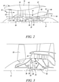
- Figure 2 illustrates an example of gas turbine engine 10' comprising a gearbox 30 provided in the drive train from a turbine to the fan.
- the gas turbine engine 10' has a longitudinal axis 11 and comprises a propulsive fan 53 and an engine core 41 comprising in axial flow series, a low pressure compressor 44, a high-pressure compressor 45, combustion equipment 46, a high-pressure turbine 47, a low pressure turbine 49 and a core exhaust nozzle 50.
- a nacelle 51 surrounds the gas turbine engine 10' and defines a bypass duct 42 and a bypass exhaust nozzle 48.
- the fan 53 is attached to and driven by the low pressure turbine 49 via a shaft 56 and an epicyclic gearbox 30.
- the epicyclic gearbox 30 is a reduction gearbox.
- FIG 3 illustrates in more detail the gas turbine engine 10' and the gearbox 30 of figure 2 .
- the gearbox 30 is of the epicyclic type.
- the low pressure turbine 49 (see Figure 2 ) drives the shaft 56, which is coupled to a sun wheel, or sun gear, 28 of the gearbox 30.
- Radially outwardly of the sun gear 28 and intermeshing therewith is a plurality of planet gears 32 that are coupled together by a planet carrier 34.
- the planet carrier 34 constrains the planet gears 32 to precess around the sun gear 28 in synchronicity whilst enabling each planet gear 32 to rotate about its own axis.
- the planet carrier 34 is coupled via linkages 36 to the fan 53 in order to drive its rotation about the longitudinal axis 11.
- an annulus or ring gear 38 Radially outwardly of the planet gears 32 and intermeshing therewith is an annulus or ring gear 38 that is coupled, via linkages 40, to a stationary supporting structure 24.
- low pressure turbine and “low pressure compressor” as used herein may be taken to mean the lowest pressure turbine stages and lowest pressure compressor stages (i.e. not including the fan 53) respectively and/or the turbine and compressor stages that are connected together by the interconnecting shaft 56 with the lowest rotational speed in the engine (i.e. not including the gearbox output shaft that drives the fan 53).
- the "low pressure turbine” and “low pressure compressor” referred to herein may alternatively be known as the “intermediate pressure turbine” and “intermediate pressure compressor”. Where such alternative nomenclature is used, the fan 53 may be referred to as a first, or lowest pressure, compression stage.
- the epicyclic gearbox 30 illustrated by way of example in Figures 3 is of the planetary type, in that the planet carrier 34 is coupled to an output shaft via linkages 36, with the ring gear 38 fixed.
- the epicyclic gearbox 30 may be a star arrangement, in which the planet carrier 34 is held fixed, with the ring (or annulus) gear 38 allowed to rotate. In such an arrangement the fan 53 is driven by the ring gear 38.
- the gearbox 30 may be a differential gearbox in which the ring gear 38 and the planet carrier 34 are both allowed to rotate.
- the present disclosure extends to a gas turbine engine having any arrangement of gearbox styles (for example star or planetary), support structures, input and output shaft arrangement, and bearing locations.
- gearbox styles for example star or planetary
- support structures for example star or planetary
- input and output shaft arrangement for example star or planetary
- bearing locations for example star or planetary
- Figures 4 and 5 illustrate an embodiment of a modular cabin blower system 200 according to the disclosure connected to an accessory gearbox 300 arranged within an accessory gearbox casing 302.
- the cabin blower system 200 includes a cabin blower 202, an electric variator 204, and a differential gearbox 206.
- the cabin blower 202 comprises a compressor 203, an air inlet 208 and an air outlet 210.
- Air from the engine for example from the bypass duct of the engine, is fed to the compressor 203 of the cabin blower 202 through the air inlet 208, compressed by the compressor 203, which in turn feeds the compressed air to the cabin of the aircraft via the air outlet 210.
- the compressor 203 may be a blower, or an impeller, or a pair of impellers.
- the electrical variator 204 includes a first electrical machine 212, a second electrical machine 214, and a power management system 216.
- the first and second electrical machines 212, 214 are each configured to work as electric motor and/or power generators.
- the power management system 216 interconnects the first and second electrical machines 212, 214 and controls whether each of the first and second electrical machines 212, 214 work as electric motor or power generator to drive the cabin blower 202 within specific operating conditions regardless the operating point of the gas turbine engine.
- the differential gearbox 206 has a first input connected to a drive output pad 240 of the accessory gearbox 300 to receive drive therefrom.
- the first electrical machine 212 is also connected to the same drive output pad 240 in this embodiment; in other embodiments, the first electrical machine 212 may be on a different drive output pad of the accessory gearbox 300.
- the differential gearbox 206 has a second input connected to the second electrical machine 214, and an output connected to the cabin blower 202.
- the electrical variator 204 and differential gearbox 206 are arranged on a first side 205 of the accessory gearbox casing 302; the cabin blower 202 is arranged on a second side 207 of the accessory gearbox casing 302 opposite the first side 205.
- the cabin blower 202, the electrical variator 204, and differential gearbox 206 are coaxially arranged along a common axis 209.
- Figure 5 illustrates in more detail the arrangement of the differential gearbox 206 and how the first electrical machine 212, the second electrical machine 214, the differential gearbox 206, and the cabin blower 202 are connected to each other.
- the differential gearbox 206 is an epicyclic gearbox 220 comprising a summing gearbox 222 and a step-up, amplifying gearbox 224.
- a common ring gear 226 mutually connects the summing gearbox 222 and the amplifying gearbox 224.
- the summing gearbox 222 is an epicyclic gearbox in a planetary arrangement and includes a sun gear 227, a plurality of planet gears 228, a carrier 229 connecting the planet gears 228, and the ring gear 226.
- the planet gears 228, according to the planetary arrangement, rotate about their own axis and precess around the sun gear 227.
- the amplifying gearbox 224 is an epicyclic gearbox in a star arrangement and comprises a sun gear 230, a plurality of planet gears 231, and the ring gear 226.
- the planet gears 231, according to the star arrangement, are held stationary with respect to the sun gear 230, and rotate about their own axis only.
- a first shaft 234, driven by the drive output pad 240 of the accessory gearbox 300, is connected to the first electrical machine 212 and to the differential gearbox 206, in particular to the planet gears 228 of the summing gearbox 222 via the carrier 229.
- the first shaft 234 represents the first input of the summing gearbox 222.
- the first shaft 234 passes through the accessory gearbox casing 302 in correspondence of the first side 205 to connect the drive output pad 240 and the carrier 229.
- the first shaft 234 is connected at a first end portion to the accessory gearbox 206 and at a second end portion to the summing gearbox 222.
- a second shaft 236 is connected to the differential gearbox 206, in particular to the sun gear 227 of the summing gearbox 222.
- the second shaft 236 represents the second input of the differential gearbox 206.
- the second shaft 236 is arranged outside the accessory gearbox 302 and does not pass through the accessory gearbox casing 302.
- a third shaft 238 is connected at a first end portion to the differential gearbox 206, in particular to the sun gear 230 of the amplifying gearbox 224, and at a second end portion is connected to, and drives, the cabin blower 202, in particular the compressor 203.
- the third shaft 238 represents the output of the differential gearbox 206.
- the third shaft 238 connects the differential gearbox 206 arranged on the first side 205 of the accessory gearbox casing 302 to the cabin blower 202 arranged on the second side 207 of the accessory gearbox casing 302, passing all the way through the accessory gearbox 300.
- first, second and third shafts 234, 236, 238 are coaxial and arranged along the common axis 209.
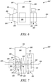
- Figure 6 and 7 illustrate a cabin blower system 200' according to an embodiment similar to the embodiment of figures 4 and 5 , and differing therefrom for the arrangement of the differential gearbox 206.
- Like features between Figures 4, 5 and 6, 7 are given like reference numerals, and will not be described in detail again in relation to Figure 6 and 7 .
- the electrical variator 204 is arranged on the first side 205 of the accessory gearbox casing 302
- the cabin blower 202 is arranged on the second side 207 of the accessory gearbox casing 302
- the differential gearbox 206 is integrated with the accessory gearbox 300 and arranged within the accessory gearbox casing 302.
- the cabin blower system 200' is particularly compact and suitable where limited space is available.
- the differential gearbox 206 is arranged only partially within the accessory gearbox casing 302 and protrudes thereof.
- integrating the differential gearbox, even only partially, within the differential gearbox may add complexity to the cabin blower system.
- the first shaft 234' is connected at a first end portion to the first electrical machine 212 and at a second end portion to the differential gearbox 206, in particular the carrier 229 of the summing gearbox 222.
- the first shaft 234' is driven by the accessory gearbox 300, which is arranged between the electrical variator 204 and the differential gearbox 206.
- gears of the accessory gearbox 300 are connected to, and drive, the first shaft 234' and are arranged at an axial position along the first shaft 234' between the differential gearbox 206 and the first electrical machine 212.
- the second shaft 236' connects the second electrical machine 214 to the sun gear 227 of the summing gearbox 222.
- the sun gear 227 is arranged within the accessory gearbox 300 and the second electrical machine 214 is arranged outside the accessory gearbox 30, the second shaft 236' passes through the first side 205 of the accessory gearbox casing 302 and is longer than the second shaft 236 of the figure 4 and 5 embodiment.
- the third shaft 238' is connected to the differential gearbox 206, in particular to the sun gear 230 of the amplifying gearbox 224, and drives the cabin blower 202.
- the sun gear 230 is arranged within the accessory gearbox 300 and the cabin blower 202 is arranged outside the accessory gearbox 300 on the second side 207
- the third shaft 238' passes through the second side 207 of the accessory gearbox casing 302.
- the third shaft 238' is shorter than the third shaft 238 of the figure 4 and 5 embodiment.
- first, second and third shafts 234', 236', 238' are coaxial and arranged along the common axis 209.
- Figure 9-15 illustrate various embodiments of cabin blower systems according to the disclosure, wherein the electrical variator 204 is arranged on the first side 205 of the accessory gearbox casing 302, and the cabin blower 202 is arranged on the second side 207 of the accessory gearbox casing 302.
- the electrical variator 204 is arranged on the first side 205 of the accessory gearbox casing 302
- the cabin blower 202 is arranged on the second side 207 of the accessory gearbox casing 302.
- Like features between Figure 4-7 and 9-15 are given like reference numerals, and will not be described in detail again in relation to Figure 9-15 .
- figure 9 illustrates a cabin blower system 400 wherein the differential gearbox 206 is partly integrated in the accessory gearbox 300 and protrudes from the second side 207 of the accessory gearbox casing 302.
- the electric variator 204 is arranged on the first side 205 of the accessory gearbox casing 302.
- the first electrical machine 212 and the second electrical machines 214 are connected to the first shaft, and the second shaft, not shown for sake of simplicity.
- the first shaft and the second shaft are not coaxial.
- the first shaft is arranged on a first axis 401
- the second shaft is arranged on a second axis 402.
- the first axis 401 and the second axis 402 may, as in the illustrated embodiment, or may not, be parallel.
- the first shaft is directly connected to the differential gearbox 206; the second shaft is connected to the differential gearbox 206 through known, and therefore not illustrated, gear systems.
- the cabin blower 202 Connected to the differential gearbox 206 and arranged on the second side 207 of the accessory gearbox 300 there is the cabin blower 202 with the compressor 203, the air inlet 208 and the air outlet 210.
- the compressor 203 is driven by a third shaft, not shown for sake of simplicity, arranged on a third axis 403, coaxial to the first axis 401.
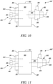
- Figure 10 illustrates a cabin blower system 400' which differs from the cabin blower system 400 of figure 9 in that the first axis 401 and the third axis 403 are not coaxial.
- the differential gearbox 206 and the cabin blower 202 are arranged such that the third axis 403 is parallel to the first axis 401 and the second axis 402, and is equidistant therefrom.
- the third axis 403 may be closer to either the first axis 401 or the second axis 402 than the second axis 402 or the first axis 401, respectively.
- first, second, and third axis 401, 402, 403 may not be mutually parallel; for example, the first and second axis 401, 402 may be mutually parallel and the third axis 403 may be arranged at an angle thereto.
- gear systems connect the first and second shaft to the differential gearbox 206.
- Figure 11 illustrates a cabin blower system 400" which differs from the cabin blower system 400' of figure 10 in that the differential gearbox 206 is not integrated in the accessory gearbox 300 and is arranged outside thereof.
- the differential gearbox is arranged on the second side 207 of the accessory gearbox casing 302 between the accessory gearbox 300 and the cabin blower 202.
- the differential gearbox 206 and the cabin blower 202 are arranged such that the third axis 403 is coaxial to the first axis, as in the embodiment of figure 9 .
- Such embodiment would differ from the embodiment of figure 9 in that the differential gearbox 206 is not integrated in the accessory gearbox 300.
- Figures 12, 13 , and 14 illustrate further embodiments of cabin blower systems according to the disclosure wherein the first, second, and third shafts (not illustrated for sake of simplicity) are arranged such that their respective first, second, and third axis are coaxial and arranged on a common axis 509.
- the electrical variator 204 is arranged on the first side 205 of the accessory gearbox 300 and the first and second electrical machines 212, 214 are arranged coaxially.
- the first electrical machine 212 is arranged between the second electrical machine 214 and the accessory gearbox 300.
- the second electrical machine 214 is arranged between the first electrical machine 212 and the accessory gearbox 300.
- the differential gearbox 206 is arranged on the second side 207 of the accessory gearbox casing 302 and may be partly integrated in the accessory gearbox 300, as in the cabin blower system 500 of figure 12 and in the cabin blower system 500" of figure 14 , or arranged outside the accessory gearbox 300 as in the cabin blower system 500'of figure 13 .
- the cabin blower system 500" of figure 14 differs from the cabin blower systems 500, 500' of figures 12 and 13 in that it includes a cabin blower 502 different from the cabin blower 202.
- the cabin blower 502 comprises a compressor 203 in the form of a pair of impellers 503 and an air inlet system 504 comprising a manifold 508 and two inlet ducts 510.
- the impellers 503 are arranged back to back in order to minimise/eliminate thrust load.
- the impellers may be positioned on opposing faces of the accessory gearbox, for example on a coaxial shaft.
- Air from the engine for example from the bypass duct of the engine, is fed to the manifold 508 and in turn to the impellers 503 through the air inlet ducts 510, compressed by the impellers 503, which in turn feeds the compressed air to the cabin of the aircraft via the air outlet 210.
- Each inlet duct 510 feeds a respective impeller 503.
- Figure 15 illustrates an embodiment of cabin blower system 600 wherein the electric variator 204 is arranged on the first side 205 of the accessory gearbox casing 302 with the first electrical machine 212 and the second electrical machine 214 coaxially arranged.
- a first and a second shaft (not shown for sake of simplicity) are connected to the first electrical machine 212 and the second electrical machine 214, respectively, and are arranged along respective first and second axis 601, 602.
- the first and second axis 601, 602 are coaxial.
- the differential gearbox 206 and the cabin blower 202 are arranged on the second side 207 of the accessory gearbox casing 302.
- the cabin blower 202 includes a compressor 203 driven by a third shaft, not shown for sake of simplicity, arranged on a third axis 603.
- the first and second axis 601, 602 are parallel to the third axis 603, and mutually distanced.
- the first shaft and the second shaft are connected to the differential gearbox 206 through a known, and therefore not illustrated, gear system.
- FIGS 16-18 illustrate embodiments of cabin blower systems wherein the cabin blower 202, the electric variator 204, and the differential gearbox 206 are all arranged on a same side of the accessory gearbox casing 302.
- the cabin blower 202, the electric variator 204, and the differential gearbox 206 may be seen as arranged on the second side 207 of the accessory gearbox casing 302, but the skilled person would recognise that any side of the accessory gearbox casing 302 may be referred to as the second side 207.
- FIG 16 there is illustrated an embodiment of a cabin blower system 700, wherein the first and second machines 212, 214 of the electric variator 204 are arranged such that the first and second shaft (not illustrated for sake of simplicity) are coaxially arranged along coincident first and second axis 701, 702.
- the cabin blower system 700 further comprise a differential gearbox 206 partially integrated within the accessory gearbox 300 as in the embodiments of figures 8-10 , 12 , and 14 .
- a known gear system connects the first and second shaft to the differential gearbox 206.
- the cabin blower 202 comprises a compressor 203 driven by the third shaft (not shown) arranged along a third axis 703, parallel to, but not coincident with, the first and second axis 701, 702.
- Figure 17 illustrates a further embodiment of a cabin blower system 700' which differs from the cabin blower system 700 of figure 16 in that the differential gearbox 206 is not partially integrated with accessory gearbox 300.
- the accessory gearbox 206 protrudes from the accessory gearbox casing 302 and is arranged between the accessory gearbox 300 and the cabin blower 202.
- FIG 18 illustrates another embodiment of a cabin blower system 700" which differs from the cabin blower systems 700 and 700' of figures 16 and 17 in that the differential gearbox 206 is arranged at a distance from the accessory gearbox 300.
- the cabin blower system 700" comprises an electric variator 204 with first and second electric machines 212, 214 arranged adjacent to the accessory gearbox 300 (as in the embodiments of figures 16 and 17 ), and a differential gearbox 206, connected to the first and second electrical machines 212, 214 through known gears (not shown for sake of simplicity) and arranged at a distance from the accessory gearbox 300.
- the first and second shaft (not illustrated) connected to the first and second electric machines 212, 214 are arranged along the first and second axis 701, 702, respectively.
- the cabin blower system 700" further comprises a cabin blower 202 connected to the differential gearbox through the third shaft (not illustrated) such as to be arranged at a distance from the accessory gearbox 300.
- the third shaft is arranged along the third axis 703.
- the first and second axis 701, 702 and the third axis 703 are parallel and mutually distanced.
- the cabin blower systems according to the disclosure and illustrated with reference to figures 4-18 comprise an accessory gearbox 300 that can be mounted either axially or circumferentially in the gas turbine engine.
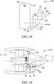
- Figure 19 illustrates an embodiment of gas turbine engine according the disclosure wherein the accessory gearbox 300 is arranged axially, or in other words substantially parallel to the longitudinal axis 11 of the gas turbine engine, in a core accessory bay 110.
- the gas turbine engine may be either a direct drive gas turbine engine as the gas turbine engine 10 of figure 1 , or a geared gas turbine engine as the gas turbine engine 10' of figures 2 and 3 .
- the accessory gearbox 300 comprises a plurality of drive output pads 309, one of which is connected to a cabin blower system 111 of the type described with reference to figures 4-18 .
- Engine and airframe accessories (not illustrated), such for example fuel and oil pumps, are connected to the remaining drive output pads 309.
- Fan air is scooped from the fan stream in the bypass duct 22 by means of a fan air offtake 112 connected to the air inlet of the cabin blower, compressed by the compressor (or impellers) of the cabin blower, and delivered through the air outlet 210 to the aircraft for cabin ventilation and pressurisation.
- the fan air offtake 112 is arranged in the bypass duct 22 and protrudes from a core faring 113 which defines a radially inner surface of the bypass duct 22. It is to be noted that such arrangement allows a short fan air offtake 112.
- the fan air offtake 112 is arranged in the bypass duct 22 and protrudes from a nacelle inner wall.
- the gas turbine engine may further comprise a heat exchanger 114 mounted from the core fairing 113 and configured to dissipate heat generated by the cabin blower system.
- heat generated by the cabin blower system may be dissipated by the engine cooling circuit (not illustrated).
- the heat exchanger 114 is used to dissipate heat from the cabin blower system, and can be a surface heat exchanger mounted from the engine core fairings 113 as illustrated, so that the heat exchanger is cooled by the fan by-pass air. Equally the surface cooler could be mounted on any surface of the bypass duct 42 or splitters 116,117. Ideally the heat exchanger is mounted in close proximity to the cabin blower system.
- a matrix heat exchanger fed by a dedicated offtake from the bypass duct 42 would be another means (not illustrated) of cooling the cabin blower system.
- the fan air offtake may be arranged differently from the fan air offtake 112.
- the fan air offtake 112' is arranged at a splitter faring.
- figure 20 illustrates a gas turbine engine 10, 10' of the type illustrated with reference to figures 1-3 , comprising an accessory gearbox 300 arranged circumferentially from the core.
- a cabin blower system 111 of the type illustrated with reference to figures 4-18 is connected to one of the drive output pads of the accessory gearbox 300.
- Engine and airframe accessories 118 such for example fuel and oil pumps, are connected to the remaining drive output pads 109.
- the gas turbine engine further comprises an upper bifurcation, or upper splitter, 116 and a lower bifurcation, or lower splitter, 117 spanning the bypass duct 22.
- the upper splitter 116 and the lower splitter 117 comprise respective leading edges, trailing edges and a first and a second sidewalls connecting the leading edges and the trailing edges.
- the fan air offtake 112' may be either a forward facing offtake arranged on the lower splitter leading edge (as illustrated in figure 20 ), or a scoop on either the first or second sidewalls of the lower splitter 117. In alternative non-illustrated embodiments the fan air offtake 112' may be either a forward facing offtake arranged on the upper splitter leading edge, or a scoop on either the first or second sidewalls of the upper splitter 116.
- the fan air offtake 112' provides air to the cabin blower 202 to be compressed by the compressor (or impellers) and delivered through the air outlet 210 to the aircraft for cabin ventilation and pressurisation.
Landscapes
- Engineering & Computer Science (AREA)
- Chemical & Material Sciences (AREA)
- Combustion & Propulsion (AREA)
- Mechanical Engineering (AREA)
- General Engineering & Computer Science (AREA)
- Aviation & Aerospace Engineering (AREA)
- Health & Medical Sciences (AREA)
- General Health & Medical Sciences (AREA)
- Pulmonology (AREA)
- Structures Of Non-Positive Displacement Pumps (AREA)
- Physics & Mathematics (AREA)
- Fluid Mechanics (AREA)
Abstract
Description
- The present disclosure relates to cabin blower systems for aircraft, and in particular to a modular cabin blower system for an aircraft.
- Cabin blower systems are known for pressurising the cabin of an aircraft. Cabin blower systems provide an airflow to cabins of an aircraft at a controlled temperature and pressure for ventilation. The pressurised air from the cabin blower can also be used for other aircraft functions e.g. wing anti-icing, fuel tank inerting, cargo heating, and other aircraft systems pressurisation (e.g. hydraulic and potable water), A cabin blower system includes a cabin blower typically driven by a compressor, which in turn is driven by a shaft of the gas turbine engine via an accessory gearbox. As it is not desirable for the compressor of the cabin blower to rotate at a speed determined by the particular operating point of the gas turbine at any particular moment, the cabin blower system normally includes a variable drive system to vary the compressor speed and keep the cabin airflow and pressure within acceptable limits. The cabin blower is driven by the variable drive system, which in turn is connected to, and driven by, the accessory gearbox. The accessory gearbox is arranged in a core engine accessory bay, which is normally quite congested. As the variable drive system includes several components, such as electrical motors/generators and a summing gearbox, and is integrated with the cabin blower into a single combined unit, known cabin blower systems are bulky and present several installation and integration challenges.
- There is therefore a need for a cabin blower system with improved installation and integration capabilities.
- According to a first aspect, there is provided a gas turbine engine including an engine core including a compressor, a combustor, and a turbine, the compressor being connected to the turbines through a respective shaft; a cabin blower system comprising: an electric variator comprising a first electrical machine connected to a first shaft arranged along a first axis, a second electrical machine connected to a second shaft arranged along a second axis, and a power management system; a cabin blower comprising a compressor driven by a third shaft, the compressor comprising an air inlet and an air outlet; and a differential gearbox. The gas turbine engine further includes an accessory gearbox arranged within an accessory gearbox casing and adapted to drive the cabin blower system.
- In one group of embodiments, the first and second electrical machines are arranged on a first side of the accessory gearbox casing and the cabin blower is arranged on a second side of the accessory gearbox casing.
- In another group of embodiments, the first electrical machine, the second electrical machine, and the cabin blower are arranged on a same side of the accessory gearbox casing such that the third shaft is not coaxial with either the first or the second shaft.
- The cabin blower, the first electrical machine, the second electrical machine, and the differential gearbox may be configured as modules, such that the cabin blower system may be configured to best fit in the core engine accessory bay where the accessory gearbox is arranged.
- Contrary to the known cabin blower systems, the cabin blower, the first electrical machine, the second electrical machine, and the differential gearbox of the present disclosure may be split and arranged to be housed where space is available around the accessory gearbox.
- Depending on the available space in the core engine accessory bay, the cabin blower, first electrical machine, second electrical machine, and differential gearbox may be split in two or more groups of modules and arranged on a single side of the accessory gearbox, or on two different sides of the accessory gearbox casing. The two different sides of the accessory gearbox casing may be opposite to each other.
- The latter arrangements, with the modules split in groups on opposite sides of the accessory gearbox, may be particularly advantageous, as it may allow for a more compact arrangement and may reduce overhang and unbalance.
- For example, the electric variator may be arranged on a first side of the accessory gearbox casing and the differential gearbox and/or the cabin blower may be arranged on a second side of the accessory gearbox casing. The first side of the accessory gearbox casing may be opposite to the second side of the accessory gearbox casing.
- The electric variator and the differential gearbox may be arranged on a common axis. Alternatively, the electric variator and the differential gearbox may be arranged on separate axes.
- The electric variator and the cabin blower may be arranged on a common axis. Alternatively, the electric variator and the cabin blower may be arranged on separate axes.
- The second side of the accessory gearbox may be opposite the first side of the accessory gearbox.
- The accessory gearbox may include a plurality of drive output pads to connect with a number of engine accessories, including fuel and oil pumps.
- The accessory gearbox is arranged within an accessory gearbox casing. The accessory gearbox and accessory gearbox casing may be arranged either axially, substantially parallel to a longitudinal axis of the gas turbine engine, or circumferentially about the longitudinal axis of the gas turbine engine.
- The first and second electrical machines of the electric variator may be either ganged and coaxial, i.e. such that the first and second shafts are coaxial, or separate and arranged such that the first and second shafts are arranged on different axes.
- At least one of the first and second shafts may be coaxial with a drive output pad of the plurality of drive output pads of the accessory gearbox.
- The differential gearbox may be connected to, and coaxial with, a drive output pad of the plurality of drive output pads of the differential gearbox.
- The cabin blower compressor may be arranged coaxially with the differential gearbox. The cabin blower compressor may be a centrifugal fan, one or more impellers, or any other known devices adapted to increase pressure of a gas.
- The first shaft, the second shaft, and the third shaft may be arranged on respective, non-coincident axes.
- The first and second electrical machines may be ganged and the first and second shafts may be coaxial with a drive output pad of the differential gearbox.
- The cabin blower and the differential gearbox may be ganged and arranged on one side of the accessory gearbox.
- The differential gearbox may comprise a first input connected the accessory gearbox, for example via the first shaft, a second input connected to the second shaft, and an output connected to the third shaft.
- The output of the differential gearbox may be connected to the compressor of the cabin blower.
- The differential gearbox may be an epicyclic gearbox comprising a summing gearbox and a step-up, amplifying gearbox.
- The summing gearbox may be an epicyclic gearbox in a planetary configuration and may comprise a sun gear, a plurality of planet gears, a carrier connecting the planet gears, and a ring gear.
- The first shaft may connect the accessory gearbox and the first electrical machine to drive the planet gears of the summing gearbox through the carrier, and the second shaft may connect the second electrical machine to the sun gear of the summing gearbox.
- The step-up, amplifying gearbox may be an epicyclic gearbox in a star arrangement and may comprise a sun gear connected to the third shaft to drive the cabin blower.
- The first and second electrical machines of the electric variator may be independently configured to work as electric motors and/or as power generators.
- The gas turbine engine may further comprise a fan air offtake adapted to feed air to the cabin blower through the air inlet.
- The gas turbine engine may comprise a bypass duct, and the fan air offtake may be arranged in the bypass duct.
- The gas turbine engine may further comprise a bifurcation, or splitter, spanning the bypass duct and comprising a leading edge, a trailing edge, and a first and a second sidewall connecting the leading edge and the trailing edge. The fan air offtake may be either a forward facing offtake arranged on the bifurcation leading edge, or either a flush scoop or forward facing scoop on either the first or second sidewalls of the bifurcation.
- The gas turbine engine may further comprise a heat exchanger to cool the cabin blower system. The heat exchanger may be either a surface heat exchanger or matrix cooler.
- The heat exchanger may be a surface heat exchanger mounted from fairings of the engine core.
- The compressor of the cabin blower may be a dual impeller, mounted from a single side of the gearbox casing. Alternatively, each impeller of the dual impeller may be mounted on opposite sides of the gearbox casing on a coaxial shaft.
- In the present disclosure, upstream and downstream are with respect to the air flow through the compressor, and front and rear is with respect to the gas turbine engine, i.e. the fan being in the front and the turbine being in the rear of the engine. As used herein, forward refers to the direction from the rear to the front of the gas turbine engine.
- The gas turbine engine may comprise an upper bifurcation, or upper splitter, and a lower bifurcation, or lower splitter, spanning the bypass duct and the fan air offtake may be arranged either on the upper splitter, or the lower splitter.
- The skilled person will appreciate that except where mutually exclusive, any feature described herein may be applied to and/or combined with any other feature described herein.
- Embodiments will now be described by way of example only, with reference to the Figures, in which:
-
Figure 1 is a sectional side view of a gas turbine engine; -
Figure 2 is a sectional side view of a geared gas turbine engine; -
Figure 3 is a close up sectional side view of an upstream portion of the geared gas turbine engine offigure 2 ; -
Figure 4 is a schematic view of a cabin blower system connected to an accessory gearbox according to an embodiment; -
Figure 5 is a schematic view of the cabin blower system and accessory gearbox offigure 4 showing the gear arrangement; -
Figure 6 is a schematic view of a cabin blower system connected to an accessory gearbox according to another embodiment; -
Figure 7 is a schematic view of the cabin blower system and accessory gearbox offigure 6 showing the gear arrangement; -
Figures 8 - 15 are schematic views of cabin blower system and accessory gearbox wherein the cabin blower system is split into modules arranged on different sides of the accessory gearbox according to different embodiments; -
Figures 16 - 18 are schematic views of cabin blower system and accessory gearbox wherein the cabin blower system is split into modules arranged on a same side of the accessory gearbox according to different embodiments; -
Figure 19 is a sectional side view of a gas turbine engine illustrating an accessory gearbox in a first configuration; and -
Figure 20 is a sectional side view of a gas turbine engine illustrating an accessory gearbox in a second configuration. - With reference to
Figure 1 , a gas turbine engine, generally indicated at 10, has alongitudinal axis 11. Theengine 10 comprises, in axial flow series, anair intake 12, apropulsive fan 13, anintermediate pressure compressor 14, a high-pressure compressor 15,combustion equipment 16, a high-pressure turbine 17, anintermediate pressure turbine 18, a low-pressure turbine 19 and anexhaust nozzle 20. Anacelle 21 generally surrounds theengine 10 and defines both theintake 12 and theexhaust nozzle 20. - The
gas turbine engine 10 works in the conventional manner so that air entering theintake 12 is accelerated by thefan 13 to produce two air flows: a first air flow into theintermediate pressure compressor 14 and a second air flow which passes through abypass duct 22 to provide propulsive thrust. Theintermediate pressure compressor 14 compresses the air flow directed into it before delivering that air to thehigh pressure compressor 15 where further compression takes place. - The compressed air exhausted from the high-
pressure compressor 15 is directed into thecombustion equipment 16 where it is mixed with fuel and the mixture combusted. The resultant hot combustion products then expand through, and thereby drive the high, intermediate and low-pressure turbines nozzle 20 to provide additional propulsive thrust. The high 17, intermediate 18 and low 19 pressure turbines drive respectively thehigh pressure compressor 15,intermediate pressure compressor 14 andfan 13, each by suitable interconnecting shaft. - Other gas turbine engines to which the present disclosure may be applied may have alternative configurations. By way of example, such engines may have an alternative number of interconnecting shafts (e.g. two) and/or an alternative number of compressors and/or turbines. Further, the engine may comprise a gearbox provided in the drive train from a turbine to a compressor and/or fan.
-
Figure 2 illustrates an example of gas turbine engine 10' comprising agearbox 30 provided in the drive train from a turbine to the fan. - The gas turbine engine 10' has a
longitudinal axis 11 and comprises apropulsive fan 53 and anengine core 41 comprising in axial flow series, alow pressure compressor 44, a high-pressure compressor 45,combustion equipment 46, a high-pressure turbine 47, alow pressure turbine 49 and acore exhaust nozzle 50. Anacelle 51 surrounds the gas turbine engine 10' and defines abypass duct 42 and abypass exhaust nozzle 48. Thefan 53 is attached to and driven by thelow pressure turbine 49 via ashaft 56 and anepicyclic gearbox 30. Theepicyclic gearbox 30 is a reduction gearbox. -
Figure 3 illustrates in more detail the gas turbine engine 10' and thegearbox 30 offigure 2 . Thegearbox 30 is of the epicyclic type. The low pressure turbine 49 (seeFigure 2 ) drives theshaft 56, which is coupled to a sun wheel, or sun gear, 28 of thegearbox 30. Radially outwardly of thesun gear 28 and intermeshing therewith is a plurality of planet gears 32 that are coupled together by aplanet carrier 34. Theplanet carrier 34 constrains the planet gears 32 to precess around thesun gear 28 in synchronicity whilst enabling eachplanet gear 32 to rotate about its own axis. Theplanet carrier 34 is coupled vialinkages 36 to thefan 53 in order to drive its rotation about thelongitudinal axis 11. Radially outwardly of the planet gears 32 and intermeshing therewith is an annulus orring gear 38 that is coupled, vialinkages 40, to a stationary supportingstructure 24. - Note that the terms "low pressure turbine" and "low pressure compressor" as used herein may be taken to mean the lowest pressure turbine stages and lowest pressure compressor stages (i.e. not including the fan 53) respectively and/or the turbine and compressor stages that are connected together by the interconnecting
shaft 56 with the lowest rotational speed in the engine (i.e. not including the gearbox output shaft that drives the fan 53). In some literature, the "low pressure turbine" and "low pressure compressor" referred to herein may alternatively be known as the "intermediate pressure turbine" and "intermediate pressure compressor". Where such alternative nomenclature is used, thefan 53 may be referred to as a first, or lowest pressure, compression stage. - The
epicyclic gearbox 30 illustrated by way of example inFigures 3 is of the planetary type, in that theplanet carrier 34 is coupled to an output shaft vialinkages 36, with thering gear 38 fixed. However, any other suitable type ofepicyclic gearbox 30 may be used. By way of further example, theepicyclic gearbox 30 may be a star arrangement, in which theplanet carrier 34 is held fixed, with the ring (or annulus)gear 38 allowed to rotate. In such an arrangement thefan 53 is driven by thering gear 38. By way of further alternative example, thegearbox 30 may be a differential gearbox in which thering gear 38 and theplanet carrier 34 are both allowed to rotate. - Accordingly, the present disclosure extends to a gas turbine engine having any arrangement of gearbox styles (for example star or planetary), support structures, input and output shaft arrangement, and bearing locations.
-
Figures 4 and 5 illustrate an embodiment of a modularcabin blower system 200 according to the disclosure connected to anaccessory gearbox 300 arranged within anaccessory gearbox casing 302. - The
cabin blower system 200 includes acabin blower 202, anelectric variator 204, and adifferential gearbox 206. - The
cabin blower 202 comprises acompressor 203, anair inlet 208 and anair outlet 210. Air from the engine, for example from the bypass duct of the engine, is fed to thecompressor 203 of thecabin blower 202 through theair inlet 208, compressed by thecompressor 203, which in turn feeds the compressed air to the cabin of the aircraft via theair outlet 210. Thecompressor 203 may be a blower, or an impeller, or a pair of impellers. - The
electrical variator 204 includes a firstelectrical machine 212, a secondelectrical machine 214, and apower management system 216. - The first and second
electrical machines power management system 216 interconnects the first and secondelectrical machines electrical machines cabin blower 202 within specific operating conditions regardless the operating point of the gas turbine engine. - The
differential gearbox 206 has a first input connected to adrive output pad 240 of theaccessory gearbox 300 to receive drive therefrom. - The first
electrical machine 212 is also connected to the samedrive output pad 240 in this embodiment; in other embodiments, the firstelectrical machine 212 may be on a different drive output pad of theaccessory gearbox 300. - The
differential gearbox 206 has a second input connected to the secondelectrical machine 214, and an output connected to thecabin blower 202. - The
electrical variator 204 anddifferential gearbox 206 are arranged on afirst side 205 of theaccessory gearbox casing 302; thecabin blower 202 is arranged on asecond side 207 of theaccessory gearbox casing 302 opposite thefirst side 205. - The
cabin blower 202, theelectrical variator 204, anddifferential gearbox 206 are coaxially arranged along acommon axis 209. -
Figure 5 illustrates in more detail the arrangement of thedifferential gearbox 206 and how the firstelectrical machine 212, the secondelectrical machine 214, thedifferential gearbox 206, and thecabin blower 202 are connected to each other. - The
differential gearbox 206 is an epicyclic gearbox 220 comprising a summinggearbox 222 and a step-up, amplifyinggearbox 224. - A
common ring gear 226 mutually connects the summinggearbox 222 and the amplifyinggearbox 224. The summinggearbox 222 is an epicyclic gearbox in a planetary arrangement and includes asun gear 227, a plurality of planet gears 228, acarrier 229 connecting the planet gears 228, and thering gear 226. The planet gears 228, according to the planetary arrangement, rotate about their own axis and precess around thesun gear 227. - The amplifying
gearbox 224 is an epicyclic gearbox in a star arrangement and comprises asun gear 230, a plurality of planet gears 231, and thering gear 226. The planet gears 231, according to the star arrangement, are held stationary with respect to thesun gear 230, and rotate about their own axis only. - A
first shaft 234, driven by thedrive output pad 240 of theaccessory gearbox 300, is connected to the firstelectrical machine 212 and to thedifferential gearbox 206, in particular to the planet gears 228 of the summinggearbox 222 via thecarrier 229. Thefirst shaft 234 represents the first input of the summinggearbox 222. Thefirst shaft 234 passes through theaccessory gearbox casing 302 in correspondence of thefirst side 205 to connect thedrive output pad 240 and thecarrier 229. Thefirst shaft 234 is connected at a first end portion to theaccessory gearbox 206 and at a second end portion to the summinggearbox 222. - A
second shaft 236 is connected to thedifferential gearbox 206, in particular to thesun gear 227 of the summinggearbox 222. Thesecond shaft 236 represents the second input of thedifferential gearbox 206. Thesecond shaft 236 is arranged outside theaccessory gearbox 302 and does not pass through theaccessory gearbox casing 302. - A
third shaft 238 is connected at a first end portion to thedifferential gearbox 206, in particular to thesun gear 230 of the amplifyinggearbox 224, and at a second end portion is connected to, and drives, thecabin blower 202, in particular thecompressor 203. Thethird shaft 238 represents the output of thedifferential gearbox 206. Thethird shaft 238 connects thedifferential gearbox 206 arranged on thefirst side 205 of theaccessory gearbox casing 302 to thecabin blower 202 arranged on thesecond side 207 of theaccessory gearbox casing 302, passing all the way through theaccessory gearbox 300. - In the embodiment of
figure 4 and 5 , the first, second andthird shafts common axis 209. -
Figure 6 and 7 illustrate a cabin blower system 200' according to an embodiment similar to the embodiment offigures 4 and 5 , and differing therefrom for the arrangement of thedifferential gearbox 206. Like features betweenFigures 4, 5 and6, 7 are given like reference numerals, and will not be described in detail again in relation toFigure 6 and 7 . - In the
figure 6 and 7 embodiment theelectrical variator 204 is arranged on thefirst side 205 of theaccessory gearbox casing 302, thecabin blower 202 is arranged on thesecond side 207 of theaccessory gearbox casing 302, and thedifferential gearbox 206 is integrated with theaccessory gearbox 300 and arranged within theaccessory gearbox casing 302. The cabin blower system 200' is particularly compact and suitable where limited space is available. In alternative embodiments, for example in thecabin blower system 200" illustrated infigure 8 , thedifferential gearbox 206 is arranged only partially within theaccessory gearbox casing 302 and protrudes thereof. However, without limitation, integrating the differential gearbox, even only partially, within the differential gearbox may add complexity to the cabin blower system. - The first shaft 234' is connected at a first end portion to the first
electrical machine 212 and at a second end portion to thedifferential gearbox 206, in particular thecarrier 229 of the summinggearbox 222. The first shaft 234' is driven by theaccessory gearbox 300, which is arranged between theelectrical variator 204 and thedifferential gearbox 206. In details, gears of theaccessory gearbox 300 are connected to, and drive, the first shaft 234' and are arranged at an axial position along the first shaft 234' between thedifferential gearbox 206 and the firstelectrical machine 212. - The second shaft 236' connects the second
electrical machine 214 to thesun gear 227 of the summinggearbox 222. As thesun gear 227 is arranged within theaccessory gearbox 300 and the secondelectrical machine 214 is arranged outside theaccessory gearbox 30, the second shaft 236' passes through thefirst side 205 of theaccessory gearbox casing 302 and is longer than thesecond shaft 236 of thefigure 4 and 5 embodiment. - The third shaft 238' is connected to the
differential gearbox 206, in particular to thesun gear 230 of the amplifyinggearbox 224, and drives thecabin blower 202. As thesun gear 230 is arranged within theaccessory gearbox 300 and thecabin blower 202 is arranged outside theaccessory gearbox 300 on thesecond side 207, the third shaft 238' passes through thesecond side 207 of theaccessory gearbox casing 302. The third shaft 238' is shorter than thethird shaft 238 of thefigure 4 and 5 embodiment. - Like in the embodiment of
figure 4 and 5 , the first, second and third shafts 234', 236', 238' are coaxial and arranged along thecommon axis 209. -
Figure 9-15 illustrate various embodiments of cabin blower systems according to the disclosure, wherein theelectrical variator 204 is arranged on thefirst side 205 of theaccessory gearbox casing 302, and thecabin blower 202 is arranged on thesecond side 207 of theaccessory gearbox casing 302. Like features betweenFigure 4-7 and9-15 are given like reference numerals, and will not be described in detail again in relation toFigure 9-15 . - In detail,
figure 9 illustrates acabin blower system 400 wherein thedifferential gearbox 206 is partly integrated in theaccessory gearbox 300 and protrudes from thesecond side 207 of theaccessory gearbox casing 302. Theelectric variator 204 is arranged on thefirst side 205 of theaccessory gearbox casing 302. - The first
electrical machine 212 and the secondelectrical machines 214 are connected to the first shaft, and the second shaft, not shown for sake of simplicity. The first shaft and the second shaft are not coaxial. In particular the first shaft is arranged on afirst axis 401, and the second shaft is arranged on asecond axis 402. Thefirst axis 401 and thesecond axis 402 may, as in the illustrated embodiment, or may not, be parallel. The first shaft is directly connected to thedifferential gearbox 206; the second shaft is connected to thedifferential gearbox 206 through known, and therefore not illustrated, gear systems. - Connected to the
differential gearbox 206 and arranged on thesecond side 207 of theaccessory gearbox 300 there is thecabin blower 202 with thecompressor 203, theair inlet 208 and theair outlet 210. Thecompressor 203 is driven by a third shaft, not shown for sake of simplicity, arranged on athird axis 403, coaxial to thefirst axis 401. -
Figure 10 illustrates a cabin blower system 400' which differs from thecabin blower system 400 offigure 9 in that thefirst axis 401 and thethird axis 403 are not coaxial. Thedifferential gearbox 206 and thecabin blower 202 are arranged such that thethird axis 403 is parallel to thefirst axis 401 and thesecond axis 402, and is equidistant therefrom. In not illustrated embodiments, thethird axis 403 may be closer to either thefirst axis 401 or thesecond axis 402 than thesecond axis 402 or thefirst axis 401, respectively. In further not illustrated embodiment, the first, second, andthird axis second axis third axis 403 may be arranged at an angle thereto. Known, and therefore not illustrated, gear systems connect the first and second shaft to thedifferential gearbox 206. -
Figure 11 illustrates acabin blower system 400" which differs from the cabin blower system 400' offigure 10 in that thedifferential gearbox 206 is not integrated in theaccessory gearbox 300 and is arranged outside thereof. The differential gearbox is arranged on thesecond side 207 of theaccessory gearbox casing 302 between theaccessory gearbox 300 and thecabin blower 202. In a not illustrated embodiment, thedifferential gearbox 206 and thecabin blower 202 are arranged such that thethird axis 403 is coaxial to the first axis, as in the embodiment offigure 9 . Such embodiment would differ from the embodiment offigure 9 in that thedifferential gearbox 206 is not integrated in theaccessory gearbox 300. -
Figures 12, 13 , and14 illustrate further embodiments of cabin blower systems according to the disclosure wherein the first, second, and third shafts (not illustrated for sake of simplicity) are arranged such that their respective first, second, and third axis are coaxial and arranged on acommon axis 509. - The
electrical variator 204 is arranged on thefirst side 205 of theaccessory gearbox 300 and the first and secondelectrical machines electrical machine 212 is arranged between the secondelectrical machine 214 and theaccessory gearbox 300. In not illustrated embodiments, the secondelectrical machine 214 is arranged between the firstelectrical machine 212 and theaccessory gearbox 300. - The
differential gearbox 206 is arranged on thesecond side 207 of theaccessory gearbox casing 302 and may be partly integrated in theaccessory gearbox 300, as in thecabin blower system 500 offigure 12 and in thecabin blower system 500" offigure 14 , or arranged outside theaccessory gearbox 300 as in the cabin blower system 500'offigure 13 . - The
cabin blower system 500" offigure 14 differs from thecabin blower systems 500, 500' offigures 12 and 13 in that it includes acabin blower 502 different from thecabin blower 202. Thecabin blower 502 comprises acompressor 203 in the form of a pair ofimpellers 503 and anair inlet system 504 comprising a manifold 508 and twoinlet ducts 510. Theimpellers 503 are arranged back to back in order to minimise/eliminate thrust load. In not illustrated embodiments, the impellers may be positioned on opposing faces of the accessory gearbox, for example on a coaxial shaft. - Air from the engine, for example from the bypass duct of the engine, is fed to the manifold 508 and in turn to the
impellers 503 through theair inlet ducts 510, compressed by theimpellers 503, which in turn feeds the compressed air to the cabin of the aircraft via theair outlet 210. Eachinlet duct 510 feeds arespective impeller 503. -
Figure 15 illustrates an embodiment ofcabin blower system 600 wherein theelectric variator 204 is arranged on thefirst side 205 of theaccessory gearbox casing 302 with the firstelectrical machine 212 and the secondelectrical machine 214 coaxially arranged. In other words, a first and a second shaft (not shown for sake of simplicity) are connected to the firstelectrical machine 212 and the secondelectrical machine 214, respectively, and are arranged along respective first andsecond axis second axis differential gearbox 206 and thecabin blower 202 are arranged on thesecond side 207 of theaccessory gearbox casing 302. Thecabin blower 202 includes acompressor 203 driven by a third shaft, not shown for sake of simplicity, arranged on athird axis 603. The first andsecond axis third axis 603, and mutually distanced. The first shaft and the second shaft are connected to thedifferential gearbox 206 through a known, and therefore not illustrated, gear system. -
Figures 16-18 illustrate embodiments of cabin blower systems wherein thecabin blower 202, theelectric variator 204, and thedifferential gearbox 206 are all arranged on a same side of theaccessory gearbox casing 302. For simplicity and consistency with the nomenclature used so far, thecabin blower 202, theelectric variator 204, and thedifferential gearbox 206 may be seen as arranged on thesecond side 207 of theaccessory gearbox casing 302, but the skilled person would recognise that any side of theaccessory gearbox casing 302 may be referred to as thesecond side 207. - In
figure 16 there is illustrated an embodiment of acabin blower system 700, wherein the first andsecond machines electric variator 204 are arranged such that the first and second shaft (not illustrated for sake of simplicity) are coaxially arranged along coincident first and second axis 701, 702. - The
cabin blower system 700 further comprise adifferential gearbox 206 partially integrated within theaccessory gearbox 300 as in the embodiments offigures 8-10 ,12 , and14 . A known gear system connects the first and second shaft to thedifferential gearbox 206. - The
cabin blower 202 comprises acompressor 203 driven by the third shaft (not shown) arranged along athird axis 703, parallel to, but not coincident with, the first and second axis 701, 702. -
Figure 17 illustrates a further embodiment of a cabin blower system 700' which differs from thecabin blower system 700 offigure 16 in that thedifferential gearbox 206 is not partially integrated withaccessory gearbox 300. Theaccessory gearbox 206 protrudes from theaccessory gearbox casing 302 and is arranged between theaccessory gearbox 300 and thecabin blower 202. -
Figure 18 illustrates another embodiment of acabin blower system 700" which differs from thecabin blower systems 700 and 700' offigures 16 and 17 in that thedifferential gearbox 206 is arranged at a distance from theaccessory gearbox 300. In detail, thecabin blower system 700" comprises anelectric variator 204 with first and secondelectric machines figures 16 and 17 ), and adifferential gearbox 206, connected to the first and secondelectrical machines accessory gearbox 300. As in the embodiments offigures 16, 17 the first and second shaft (not illustrated) connected to the first and secondelectric machines cabin blower system 700" further comprises acabin blower 202 connected to the differential gearbox through the third shaft (not illustrated) such as to be arranged at a distance from theaccessory gearbox 300. The third shaft is arranged along thethird axis 703. The first and second axis 701, 702 and thethird axis 703 are parallel and mutually distanced. - The cabin blower systems according to the disclosure and illustrated with reference to
figures 4-18 comprise anaccessory gearbox 300 that can be mounted either axially or circumferentially in the gas turbine engine. -
Figure 19 illustrates an embodiment of gas turbine engine according the disclosure wherein theaccessory gearbox 300 is arranged axially, or in other words substantially parallel to thelongitudinal axis 11 of the gas turbine engine, in a coreaccessory bay 110. The gas turbine engine may be either a direct drive gas turbine engine as thegas turbine engine 10 offigure 1 , or a geared gas turbine engine as the gas turbine engine 10' offigures 2 and 3 . - The
accessory gearbox 300 comprises a plurality ofdrive output pads 309, one of which is connected to acabin blower system 111 of the type described with reference tofigures 4-18 . Engine and airframe accessories (not illustrated), such for example fuel and oil pumps, are connected to the remainingdrive output pads 309. - Fan air is scooped from the fan stream in the
bypass duct 22 by means of afan air offtake 112 connected to the air inlet of the cabin blower, compressed by the compressor (or impellers) of the cabin blower, and delivered through theair outlet 210 to the aircraft for cabin ventilation and pressurisation. Thefan air offtake 112 is arranged in thebypass duct 22 and protrudes from a core faring 113 which defines a radially inner surface of thebypass duct 22. It is to be noted that such arrangement allows a shortfan air offtake 112. In alternative embodiments, thefan air offtake 112 is arranged in thebypass duct 22 and protrudes from a nacelle inner wall. - The gas turbine engine may further comprise a
heat exchanger 114 mounted from the core fairing 113 and configured to dissipate heat generated by the cabin blower system. Alternatively, heat generated by the cabin blower system may be dissipated by the engine cooling circuit (not illustrated). - The
heat exchanger 114 is used to dissipate heat from the cabin blower system, and can be a surface heat exchanger mounted from theengine core fairings 113 as illustrated, so that the heat exchanger is cooled by the fan by-pass air. Equally the surface cooler could be mounted on any surface of thebypass duct 42 or splitters 116,117. Ideally the heat exchanger is mounted in close proximity to the cabin blower system. - Note a matrix heat exchanger fed by a dedicated offtake from the
bypass duct 42 would be another means (not illustrated) of cooling the cabin blower system. - The fan air offtake may be arranged differently from the
fan air offtake 112. For example, in the embodiment offigure 20 , the fan air offtake 112' is arranged at a splitter faring. - In detail,
figure 20 illustrates agas turbine engine 10, 10' of the type illustrated with reference tofigures 1-3 , comprising anaccessory gearbox 300 arranged circumferentially from the core. Acabin blower system 111 of the type illustrated with reference tofigures 4-18 is connected to one of the drive output pads of theaccessory gearbox 300. Engine andairframe accessories 118, such for example fuel and oil pumps, are connected to the remaining drive output pads 109. - The gas turbine engine further comprises an upper bifurcation, or upper splitter, 116 and a lower bifurcation, or lower splitter, 117 spanning the
bypass duct 22. Theupper splitter 116 and thelower splitter 117 comprise respective leading edges, trailing edges and a first and a second sidewalls connecting the leading edges and the trailing edges. The fan air offtake 112' may be either a forward facing offtake arranged on the lower splitter leading edge (as illustrated infigure 20 ), or a scoop on either the first or second sidewalls of thelower splitter 117. In alternative non-illustrated embodiments the fan air offtake 112' may be either a forward facing offtake arranged on the upper splitter leading edge, or a scoop on either the first or second sidewalls of theupper splitter 116. - The fan air offtake 112' provides air to the
cabin blower 202 to be compressed by the compressor (or impellers) and delivered through theair outlet 210 to the aircraft for cabin ventilation and pressurisation.
Claims (15)
- A gas turbine engine including:an engine core including a compressor, a combustor, and a turbine, the compressor being connected to the turbines through a respective shaft;a cabin blower system comprising:an electric variator comprising a first electrical machine connected to a first shaft arranged along a first axis, a second electrical machine connected to a second shaft arranged along a second axis, and a power management system;a cabin blower comprising a compressor driven by a third shaft arranged along a third axis, the compressor comprising an air inlet and an air outlet; anda differential gearbox; andan accessory gearbox arranged within an accessory gearbox casing and adapted to drive the cabin blower system;wherein the first and second electrical machines are arranged on a first side of the accessory gearbox casing and the cabin blower is arranged on a second side of the accessory gearbox casing.
- The gas turbine engine of claim 1, wherein the differential gearbox is arranged on the second side of the accessory gearbox casing.
- The gas turbine engine of any one of the preceding claims, wherein the second side of the accessory gearbox casing is opposite the first side of the accessory gearbox casing.
- The gas turbine engine of any one of the preceding claims, wherein the first and second electrical machines are either ganged and coaxial, or separate and arranged such that the first and second shafts are arranged on different axes.
- The gas turbine engine of the preceding claim, wherein at least one of the first and second shafts is coaxial with a drive output pad of the accessory gearbox.
- The gas turbine engine of any one of claims 1 to 4 wherein the first shaft, the second shaft, and the third shaft are arranged on respective, non-coincident axes
- The gas turbine engine of any one of the preceding claims, wherein the first and second electrical machines are ganged and the first and second shafts are coaxial with a drive output pad of the accessory gearbox.
- The gas turbine engine of any one of the preceding claims, wherein the differential gearbox comprises a first input connected to the first shaft, a second input connected to the second shaft, and an output connected to the third shaft.
- The gas turbine engine of any one of the preceding claims, comprising a fan air offtake adapted to feed air to the cabin blower through the air inlet.
- The gas turbine engine of claim 9, comprising a bypass duct, and wherein the fan air offtake is arranged in the bypass duct.
- The gas turbine engine of the preceding claim, further comprising a bifurcation, or splitter, spanning the bypass duct and comprising a leading edge, a trailing edge and a first and a second sidewalls connecting the leading edge and the trailing edge, wherein the fan air offtake is either a forward facing offtake arranged on the bifurcation leading edge, or a scoop on either the first or second sidewalls of the bifurcation.
- The gas turbine engine of any one of the preceding claims, further comprising a heat exchanger to cool the cabin blower system, wherein the heat exchanger is either a surface heat exchanger or matrix cooler.
- The gas turbine engine of claim 12, wherein the heat exchanger is a surface heat exchanger mounted from fairings of the engine core.
- The gas turbine engine of any one of the preceding claims, wherein the compressor of the cabin blower is a dual impeller, mounted from a single side of the gearbox casing.
- An aircraft comprising the gas turbine engine of any one of the preceding claims.
Applications Claiming Priority (1)
| Application Number | Priority Date | Filing Date | Title |
|---|---|---|---|
| GB2013514.1A GB2598362A (en) | 2020-08-28 | 2020-08-28 | Modular cabin blower system for aircraft |
Publications (2)
| Publication Number | Publication Date |
|---|---|
| EP3961013A1 true EP3961013A1 (en) | 2022-03-02 |
| EP3961013B1 EP3961013B1 (en) | 2024-09-04 |
Family
ID=72749590
Family Applications (1)
| Application Number | Title | Priority Date | Filing Date |
|---|---|---|---|
| EP21188383.0A Active EP3961013B1 (en) | 2020-08-28 | 2021-07-29 | Modular cabin blower system for aircraft |
Country Status (3)
| Country | Link |
|---|---|
| US (1) | US12258908B2 (en) |
| EP (1) | EP3961013B1 (en) |
| GB (1) | GB2598362A (en) |
Families Citing this family (3)
| Publication number | Priority date | Publication date | Assignee | Title |
|---|---|---|---|---|
| FR3117530B1 (en) * | 2020-12-15 | 2024-01-05 | Safran Aircraft Engines | Aircraft turbomachine assembly including an equipment support |
| FR3119204B1 (en) * | 2021-01-26 | 2022-12-09 | Safran Trans Systems | TRIPLE FLOW AIRCRAFT TURBOMACHINE EQUIPPED WITH A POWER TRANSMISSION MODULE |
| US20260022669A1 (en) * | 2024-07-22 | 2026-01-22 | The Boeing Company | Accessory Gearbox with Accessories with a Stacked Configuration |
Citations (4)
| Publication number | Priority date | Publication date | Assignee | Title |
|---|---|---|---|---|
| GB2076897A (en) * | 1980-06-02 | 1981-12-09 | Rockwell International Corp | Integrated auxiliary power and environmental control unit |
| US4523517A (en) * | 1980-09-02 | 1985-06-18 | Lockhead Corporation | All electric environmental control system for advanced transport aircraft |
| US20180266329A1 (en) * | 2017-03-15 | 2018-09-20 | The Boeing Company | Hybrid drive system for transferring power from a gas turbine engine of an aircraft |
| EP3517436A1 (en) * | 2018-01-26 | 2019-07-31 | Rolls-Royce plc | Cabin blower system |
Family Cites Families (8)
| Publication number | Priority date | Publication date | Assignee | Title |
|---|---|---|---|---|
| US9470153B2 (en) * | 2011-10-05 | 2016-10-18 | United Technologies Corporation | Combined pump system for engine TMS AOC reduction and ECS loss elimination |
| US10385777B2 (en) * | 2012-10-01 | 2019-08-20 | United Technologies Corporation | Bifurcated inlet scoop for gas turbine engine |
| US10125684B2 (en) * | 2015-12-29 | 2018-11-13 | Pratt & Whitney Canada Corp. | Surface cooler for aero engine |
| FR3062421B1 (en) * | 2017-01-30 | 2021-04-16 | Safran Aircraft Engines | FUEL PUMP DRIVE DEVICE FOR TURBOMACHINE |
| US10648368B2 (en) * | 2017-03-29 | 2020-05-12 | Hamilton Sundstrand Corporation | Drive assembly for a gas turbine engine |
| GB2570478A (en) | 2018-01-26 | 2019-07-31 | Rolls Royce Plc | Cabin blower system |
| GB2570477A (en) | 2018-01-26 | 2019-07-31 | Rolls Royce Plc | Cabin blower system |
| FR3099319B1 (en) * | 2019-07-26 | 2021-06-25 | Safran Aircraft Engines | TURBOMACHINE INCLUDING AN ELECTRIC MACHINE HAVING A STARTER-GENERATOR FUNCTION AND PROCESS FOR REGULATING THE SPEED OF SUCH AN ELECTRIC MACHINE |
-
2020
- 2020-08-28 GB GB2013514.1A patent/GB2598362A/en not_active Withdrawn
-
2021
- 2021-07-29 EP EP21188383.0A patent/EP3961013B1/en active Active
- 2021-08-13 US US17/401,647 patent/US12258908B2/en active Active
Patent Citations (4)
| Publication number | Priority date | Publication date | Assignee | Title |
|---|---|---|---|---|
| GB2076897A (en) * | 1980-06-02 | 1981-12-09 | Rockwell International Corp | Integrated auxiliary power and environmental control unit |
| US4523517A (en) * | 1980-09-02 | 1985-06-18 | Lockhead Corporation | All electric environmental control system for advanced transport aircraft |
| US20180266329A1 (en) * | 2017-03-15 | 2018-09-20 | The Boeing Company | Hybrid drive system for transferring power from a gas turbine engine of an aircraft |
| EP3517436A1 (en) * | 2018-01-26 | 2019-07-31 | Rolls-Royce plc | Cabin blower system |
Also Published As
| Publication number | Publication date |
|---|---|
| EP3961013B1 (en) | 2024-09-04 |
| US20220065171A1 (en) | 2022-03-03 |
| GB2598362A (en) | 2022-03-02 |
| US12258908B2 (en) | 2025-03-25 |
| GB202013514D0 (en) | 2020-10-14 |
Similar Documents
| Publication | Publication Date | Title |
|---|---|---|
| US11719247B2 (en) | Reverse flow engine architecture | |
| US11041443B2 (en) | Multi-spool gas turbine engine architecture | |
| US11408352B2 (en) | Reverse-flow gas turbine engine | |
| US11686253B2 (en) | Through-flow gas turbine engine with electric motor and electric generator | |
| EP3992446B1 (en) | Adaptive engine with boost spool | |
| US5867979A (en) | Gas turbine engine system | |
| US12258908B2 (en) | Modular cabin blower system for aircraft | |
| US11624319B2 (en) | Reverse-flow gas turbine engine with electric motor | |
| US12078109B2 (en) | Fuel management system | |
| EP3992082B1 (en) | Gas turbine engine with cabin blower system | |
| US20230286658A1 (en) | Ram-air duct system | |
| US12435665B2 (en) | Blower system | |
| US20250136285A1 (en) | Rotary assembly | |
| EP4513022A1 (en) | Air pressurisation system | |
| US20260022669A1 (en) | Accessory Gearbox with Accessories with a Stacked Configuration |
Legal Events
| Date | Code | Title | Description |
|---|---|---|---|
| PUAI | Public reference made under article 153(3) epc to a published international application that has entered the european phase |
Free format text: ORIGINAL CODE: 0009012 |
|
| STAA | Information on the status of an ep patent application or granted ep patent |
Free format text: STATUS: THE APPLICATION HAS BEEN PUBLISHED |
|
| AK | Designated contracting states |
Kind code of ref document: A1 Designated state(s): AL AT BE BG CH CY CZ DE DK EE ES FI FR GB GR HR HU IE IS IT LI LT LU LV MC MK MT NL NO PL PT RO RS SE SI SK SM TR |
|
| STAA | Information on the status of an ep patent application or granted ep patent |
Free format text: STATUS: REQUEST FOR EXAMINATION WAS MADE |
|
| 17P | Request for examination filed |
Effective date: 20220825 |
|
| RBV | Designated contracting states (corrected) |
Designated state(s): AL AT BE BG CH CY CZ DE DK EE ES FI FR GB GR HR HU IE IS IT LI LT LU LV MC MK MT NL NO PL PT RO RS SE SI SK SM TR |
|
| GRAP | Despatch of communication of intention to grant a patent |
Free format text: ORIGINAL CODE: EPIDOSNIGR1 |
|
| STAA | Information on the status of an ep patent application or granted ep patent |
Free format text: STATUS: GRANT OF PATENT IS INTENDED |
|
| INTG | Intention to grant announced |
Effective date: 20240507 |
|
| GRAS | Grant fee paid |
Free format text: ORIGINAL CODE: EPIDOSNIGR3 |
|
| P01 | Opt-out of the competence of the unified patent court (upc) registered |
Effective date: 20240515 |
|
| GRAA | (expected) grant |
Free format text: ORIGINAL CODE: 0009210 |
|
| STAA | Information on the status of an ep patent application or granted ep patent |
Free format text: STATUS: THE PATENT HAS BEEN GRANTED |
|
| AK | Designated contracting states |
Kind code of ref document: B1 Designated state(s): AL AT BE BG CH CY CZ DE DK EE ES FI FR GB GR HR HU IE IS IT LI LT LU LV MC MK MT NL NO PL PT RO RS SE SI SK SM TR |
|
| REG | Reference to a national code |
Ref country code: GB Ref legal event code: FG4D |
|
| REG | Reference to a national code |
Ref country code: CH Ref legal event code: EP |
|
| REG | Reference to a national code |
Ref country code: IE Ref legal event code: FG4D |
|
| REG | Reference to a national code |
Ref country code: DE Ref legal event code: R096 Ref document number: 602021018207 Country of ref document: DE |
|
| REG | Reference to a national code |
Ref country code: LT Ref legal event code: MG9D |
|
| REG | Reference to a national code |
Ref country code: NL Ref legal event code: MP Effective date: 20240904 |
|
| PG25 | Lapsed in a contracting state [announced via postgrant information from national office to epo] |
Ref country code: NO Free format text: LAPSE BECAUSE OF FAILURE TO SUBMIT A TRANSLATION OF THE DESCRIPTION OR TO PAY THE FEE WITHIN THE PRESCRIBED TIME-LIMIT Effective date: 20241204 |
|
| PG25 | Lapsed in a contracting state [announced via postgrant information from national office to epo] |
Ref country code: GR Free format text: LAPSE BECAUSE OF FAILURE TO SUBMIT A TRANSLATION OF THE DESCRIPTION OR TO PAY THE FEE WITHIN THE PRESCRIBED TIME-LIMIT Effective date: 20241205 Ref country code: PL Free format text: LAPSE BECAUSE OF FAILURE TO SUBMIT A TRANSLATION OF THE DESCRIPTION OR TO PAY THE FEE WITHIN THE PRESCRIBED TIME-LIMIT Effective date: 20240904 Ref country code: FI Free format text: LAPSE BECAUSE OF FAILURE TO SUBMIT A TRANSLATION OF THE DESCRIPTION OR TO PAY THE FEE WITHIN THE PRESCRIBED TIME-LIMIT Effective date: 20240904 |
|
| PG25 | Lapsed in a contracting state [announced via postgrant information from national office to epo] |
Ref country code: BG Free format text: LAPSE BECAUSE OF FAILURE TO SUBMIT A TRANSLATION OF THE DESCRIPTION OR TO PAY THE FEE WITHIN THE PRESCRIBED TIME-LIMIT Effective date: 20240904 |
|
| PG25 | Lapsed in a contracting state [announced via postgrant information from national office to epo] |
Ref country code: LV Free format text: LAPSE BECAUSE OF FAILURE TO SUBMIT A TRANSLATION OF THE DESCRIPTION OR TO PAY THE FEE WITHIN THE PRESCRIBED TIME-LIMIT Effective date: 20240904 |
|
| PG25 | Lapsed in a contracting state [announced via postgrant information from national office to epo] |
Ref country code: HR Free format text: LAPSE BECAUSE OF FAILURE TO SUBMIT A TRANSLATION OF THE DESCRIPTION OR TO PAY THE FEE WITHIN THE PRESCRIBED TIME-LIMIT Effective date: 20240904 |
|
| PG25 | Lapsed in a contracting state [announced via postgrant information from national office to epo] |
Ref country code: ES Free format text: LAPSE BECAUSE OF FAILURE TO SUBMIT A TRANSLATION OF THE DESCRIPTION OR TO PAY THE FEE WITHIN THE PRESCRIBED TIME-LIMIT Effective date: 20240904 Ref country code: RS Free format text: LAPSE BECAUSE OF FAILURE TO SUBMIT A TRANSLATION OF THE DESCRIPTION OR TO PAY THE FEE WITHIN THE PRESCRIBED TIME-LIMIT Effective date: 20241204 |
|
| PG25 | Lapsed in a contracting state [announced via postgrant information from national office to epo] |
Ref country code: RS Free format text: LAPSE BECAUSE OF FAILURE TO SUBMIT A TRANSLATION OF THE DESCRIPTION OR TO PAY THE FEE WITHIN THE PRESCRIBED TIME-LIMIT Effective date: 20241204 Ref country code: PL Free format text: LAPSE BECAUSE OF FAILURE TO SUBMIT A TRANSLATION OF THE DESCRIPTION OR TO PAY THE FEE WITHIN THE PRESCRIBED TIME-LIMIT Effective date: 20240904 Ref country code: NO Free format text: LAPSE BECAUSE OF FAILURE TO SUBMIT A TRANSLATION OF THE DESCRIPTION OR TO PAY THE FEE WITHIN THE PRESCRIBED TIME-LIMIT Effective date: 20241204 Ref country code: LV Free format text: LAPSE BECAUSE OF FAILURE TO SUBMIT A TRANSLATION OF THE DESCRIPTION OR TO PAY THE FEE WITHIN THE PRESCRIBED TIME-LIMIT Effective date: 20240904 Ref country code: HR Free format text: LAPSE BECAUSE OF FAILURE TO SUBMIT A TRANSLATION OF THE DESCRIPTION OR TO PAY THE FEE WITHIN THE PRESCRIBED TIME-LIMIT Effective date: 20240904 Ref country code: GR Free format text: LAPSE BECAUSE OF FAILURE TO SUBMIT A TRANSLATION OF THE DESCRIPTION OR TO PAY THE FEE WITHIN THE PRESCRIBED TIME-LIMIT Effective date: 20241205 Ref country code: FI Free format text: LAPSE BECAUSE OF FAILURE TO SUBMIT A TRANSLATION OF THE DESCRIPTION OR TO PAY THE FEE WITHIN THE PRESCRIBED TIME-LIMIT Effective date: 20240904 Ref country code: ES Free format text: LAPSE BECAUSE OF FAILURE TO SUBMIT A TRANSLATION OF THE DESCRIPTION OR TO PAY THE FEE WITHIN THE PRESCRIBED TIME-LIMIT Effective date: 20240904 Ref country code: BG Free format text: LAPSE BECAUSE OF FAILURE TO SUBMIT A TRANSLATION OF THE DESCRIPTION OR TO PAY THE FEE WITHIN THE PRESCRIBED TIME-LIMIT Effective date: 20240904 |
|
| REG | Reference to a national code |
Ref country code: AT Ref legal event code: MK05 Ref document number: 1720619 Country of ref document: AT Kind code of ref document: T Effective date: 20240904 |
|
| PG25 | Lapsed in a contracting state [announced via postgrant information from national office to epo] |
Ref country code: NL Free format text: LAPSE BECAUSE OF FAILURE TO SUBMIT A TRANSLATION OF THE DESCRIPTION OR TO PAY THE FEE WITHIN THE PRESCRIBED TIME-LIMIT Effective date: 20240904 |
|
| PG25 | Lapsed in a contracting state [announced via postgrant information from national office to epo] |
Ref country code: PT Free format text: LAPSE BECAUSE OF FAILURE TO SUBMIT A TRANSLATION OF THE DESCRIPTION OR TO PAY THE FEE WITHIN THE PRESCRIBED TIME-LIMIT Effective date: 20250106 Ref country code: IS Free format text: LAPSE BECAUSE OF FAILURE TO SUBMIT A TRANSLATION OF THE DESCRIPTION OR TO PAY THE FEE WITHIN THE PRESCRIBED TIME-LIMIT Effective date: 20250104 |
|
| PG25 | Lapsed in a contracting state [announced via postgrant information from national office to epo] |
Ref country code: RO Free format text: LAPSE BECAUSE OF FAILURE TO SUBMIT A TRANSLATION OF THE DESCRIPTION OR TO PAY THE FEE WITHIN THE PRESCRIBED TIME-LIMIT Effective date: 20240904 Ref country code: SM Free format text: LAPSE BECAUSE OF FAILURE TO SUBMIT A TRANSLATION OF THE DESCRIPTION OR TO PAY THE FEE WITHIN THE PRESCRIBED TIME-LIMIT Effective date: 20240904 |
|
| PG25 | Lapsed in a contracting state [announced via postgrant information from national office to epo] |
Ref country code: EE Free format text: LAPSE BECAUSE OF FAILURE TO SUBMIT A TRANSLATION OF THE DESCRIPTION OR TO PAY THE FEE WITHIN THE PRESCRIBED TIME-LIMIT Effective date: 20240904 Ref country code: AT Free format text: LAPSE BECAUSE OF FAILURE TO SUBMIT A TRANSLATION OF THE DESCRIPTION OR TO PAY THE FEE WITHIN THE PRESCRIBED TIME-LIMIT Effective date: 20240904 |
|
| PG25 | Lapsed in a contracting state [announced via postgrant information from national office to epo] |
Ref country code: CZ Free format text: LAPSE BECAUSE OF FAILURE TO SUBMIT A TRANSLATION OF THE DESCRIPTION OR TO PAY THE FEE WITHIN THE PRESCRIBED TIME-LIMIT Effective date: 20240904 |
|
| PG25 | Lapsed in a contracting state [announced via postgrant information from national office to epo] |
Ref country code: IT Free format text: LAPSE BECAUSE OF FAILURE TO SUBMIT A TRANSLATION OF THE DESCRIPTION OR TO PAY THE FEE WITHIN THE PRESCRIBED TIME-LIMIT Effective date: 20240904 Ref country code: SK Free format text: LAPSE BECAUSE OF FAILURE TO SUBMIT A TRANSLATION OF THE DESCRIPTION OR TO PAY THE FEE WITHIN THE PRESCRIBED TIME-LIMIT Effective date: 20240904 |
|
| REG | Reference to a national code |
Ref country code: DE Ref legal event code: R097 Ref document number: 602021018207 Country of ref document: DE |
|
| PG25 | Lapsed in a contracting state [announced via postgrant information from national office to epo] |
Ref country code: DK Free format text: LAPSE BECAUSE OF FAILURE TO SUBMIT A TRANSLATION OF THE DESCRIPTION OR TO PAY THE FEE WITHIN THE PRESCRIBED TIME-LIMIT Effective date: 20240904 |
|
| PLBE | No opposition filed within time limit |
Free format text: ORIGINAL CODE: 0009261 |
|
| STAA | Information on the status of an ep patent application or granted ep patent |
Free format text: STATUS: NO OPPOSITION FILED WITHIN TIME LIMIT |
|
| 26N | No opposition filed |
Effective date: 20250605 |
|
| PG25 | Lapsed in a contracting state [announced via postgrant information from national office to epo] |
Ref country code: SE Free format text: LAPSE BECAUSE OF FAILURE TO SUBMIT A TRANSLATION OF THE DESCRIPTION OR TO PAY THE FEE WITHIN THE PRESCRIBED TIME-LIMIT Effective date: 20240904 |
|
| PGFP | Annual fee paid to national office [announced via postgrant information from national office to epo] |
Ref country code: DE Payment date: 20250728 Year of fee payment: 5 |
|
| PGFP | Annual fee paid to national office [announced via postgrant information from national office to epo] |
Ref country code: GB Payment date: 20250722 Year of fee payment: 5 |
|
| PGFP | Annual fee paid to national office [announced via postgrant information from national office to epo] |
Ref country code: FR Payment date: 20250725 Year of fee payment: 5 |
|
| REG | Reference to a national code |
Ref country code: CH Ref legal event code: H13 Free format text: ST27 STATUS EVENT CODE: U-0-0-H10-H13 (AS PROVIDED BY THE NATIONAL OFFICE) Effective date: 20260224 |
|
| PG25 | Lapsed in a contracting state [announced via postgrant information from national office to epo] |
Ref country code: LU Free format text: LAPSE BECAUSE OF NON-PAYMENT OF DUE FEES Effective date: 20250729 |
|
| REG | Reference to a national code |
Ref country code: BE Ref legal event code: MM Effective date: 20250731 |
|
| PG25 | Lapsed in a contracting state [announced via postgrant information from national office to epo] |
Ref country code: BE Free format text: LAPSE BECAUSE OF NON-PAYMENT OF DUE FEES Effective date: 20250731 |
|
| PG25 | Lapsed in a contracting state [announced via postgrant information from national office to epo] |
Ref country code: CH Free format text: LAPSE BECAUSE OF NON-PAYMENT OF DUE FEES Effective date: 20250731 |