EP3960832A1 - Coolant containing fluorinated hydrocarbon and carbon dioxide, use of same, refrigerating machine comprising same and method for operating said refrigerating machine - Google Patents
Coolant containing fluorinated hydrocarbon and carbon dioxide, use of same, refrigerating machine comprising same and method for operating said refrigerating machine Download PDFInfo
- Publication number
- EP3960832A1 EP3960832A1 EP20794832.4A EP20794832A EP3960832A1 EP 3960832 A1 EP3960832 A1 EP 3960832A1 EP 20794832 A EP20794832 A EP 20794832A EP 3960832 A1 EP3960832 A1 EP 3960832A1
- Authority
- EP
- European Patent Office
- Prior art keywords
- point
- refrigerant
- mass
- heat exchanger
- line segments
- Prior art date
- Legal status (The legal status is an assumption and is not a legal conclusion. Google has not performed a legal analysis and makes no representation as to the accuracy of the status listed.)
- Withdrawn
Links
Images









Classifications
-
- C—CHEMISTRY; METALLURGY
- C09—DYES; PAINTS; POLISHES; NATURAL RESINS; ADHESIVES; COMPOSITIONS NOT OTHERWISE PROVIDED FOR; APPLICATIONS OF MATERIALS NOT OTHERWISE PROVIDED FOR
- C09K—MATERIALS FOR MISCELLANEOUS APPLICATIONS, NOT PROVIDED FOR ELSEWHERE
- C09K5/00—Heat-transfer, heat-exchange or heat-storage materials, e.g. refrigerants; Materials for the production of heat or cold by chemical reactions other than by combustion
- C09K5/02—Materials undergoing a change of physical state when used
- C09K5/04—Materials undergoing a change of physical state when used the change of state being from liquid to vapour or vice versa
- C09K5/041—Materials undergoing a change of physical state when used the change of state being from liquid to vapour or vice versa for compression-type refrigeration systems
- C09K5/044—Materials undergoing a change of physical state when used the change of state being from liquid to vapour or vice versa for compression-type refrigeration systems comprising halogenated compounds
- C09K5/045—Materials undergoing a change of physical state when used the change of state being from liquid to vapour or vice versa for compression-type refrigeration systems comprising halogenated compounds containing only fluorine as halogen
-
- F—MECHANICAL ENGINEERING; LIGHTING; HEATING; WEAPONS; BLASTING
- F25—REFRIGERATION OR COOLING; COMBINED HEATING AND REFRIGERATION SYSTEMS; HEAT PUMP SYSTEMS; MANUFACTURE OR STORAGE OF ICE; LIQUEFACTION SOLIDIFICATION OF GASES
- F25B—REFRIGERATION MACHINES, PLANTS OR SYSTEMS; COMBINED HEATING AND REFRIGERATION SYSTEMS; HEAT PUMP SYSTEMS
- F25B13/00—Compression machines, plants or systems, with reversible cycle
-
- F—MECHANICAL ENGINEERING; LIGHTING; HEATING; WEAPONS; BLASTING
- F25—REFRIGERATION OR COOLING; COMBINED HEATING AND REFRIGERATION SYSTEMS; HEAT PUMP SYSTEMS; MANUFACTURE OR STORAGE OF ICE; LIQUEFACTION SOLIDIFICATION OF GASES
- F25B—REFRIGERATION MACHINES, PLANTS OR SYSTEMS; COMBINED HEATING AND REFRIGERATION SYSTEMS; HEAT PUMP SYSTEMS
- F25B5/00—Compression machines, plants or systems, with several evaporator circuits, e.g. for varying refrigerating capacity
- F25B5/02—Compression machines, plants or systems, with several evaporator circuits, e.g. for varying refrigerating capacity arranged in parallel
-
- F—MECHANICAL ENGINEERING; LIGHTING; HEATING; WEAPONS; BLASTING
- F25—REFRIGERATION OR COOLING; COMBINED HEATING AND REFRIGERATION SYSTEMS; HEAT PUMP SYSTEMS; MANUFACTURE OR STORAGE OF ICE; LIQUEFACTION SOLIDIFICATION OF GASES
- F25B—REFRIGERATION MACHINES, PLANTS OR SYSTEMS; COMBINED HEATING AND REFRIGERATION SYSTEMS; HEAT PUMP SYSTEMS
- F25B9/00—Compression machines, plants or systems, in which the refrigerant is air or other gas of low boiling point
- F25B9/002—Compression machines, plants or systems, in which the refrigerant is air or other gas of low boiling point characterised by the refrigerant
- F25B9/008—Compression machines, plants or systems, in which the refrigerant is air or other gas of low boiling point characterised by the refrigerant the refrigerant being carbon dioxide
-
- C—CHEMISTRY; METALLURGY
- C09—DYES; PAINTS; POLISHES; NATURAL RESINS; ADHESIVES; COMPOSITIONS NOT OTHERWISE PROVIDED FOR; APPLICATIONS OF MATERIALS NOT OTHERWISE PROVIDED FOR
- C09K—MATERIALS FOR MISCELLANEOUS APPLICATIONS, NOT PROVIDED FOR ELSEWHERE
- C09K2205/00—Aspects relating to compounds used in compression type refrigeration systems
- C09K2205/10—Components
- C09K2205/106—Carbon dioxide
-
- C—CHEMISTRY; METALLURGY
- C09—DYES; PAINTS; POLISHES; NATURAL RESINS; ADHESIVES; COMPOSITIONS NOT OTHERWISE PROVIDED FOR; APPLICATIONS OF MATERIALS NOT OTHERWISE PROVIDED FOR
- C09K—MATERIALS FOR MISCELLANEOUS APPLICATIONS, NOT PROVIDED FOR ELSEWHERE
- C09K2205/00—Aspects relating to compounds used in compression type refrigeration systems
- C09K2205/10—Components
- C09K2205/12—Hydrocarbons
- C09K2205/122—Halogenated hydrocarbons
-
- C—CHEMISTRY; METALLURGY
- C09—DYES; PAINTS; POLISHES; NATURAL RESINS; ADHESIVES; COMPOSITIONS NOT OTHERWISE PROVIDED FOR; APPLICATIONS OF MATERIALS NOT OTHERWISE PROVIDED FOR
- C09K—MATERIALS FOR MISCELLANEOUS APPLICATIONS, NOT PROVIDED FOR ELSEWHERE
- C09K2205/00—Aspects relating to compounds used in compression type refrigeration systems
- C09K2205/10—Components
- C09K2205/12—Hydrocarbons
- C09K2205/126—Unsaturated fluorinated hydrocarbons
-
- C—CHEMISTRY; METALLURGY
- C09—DYES; PAINTS; POLISHES; NATURAL RESINS; ADHESIVES; COMPOSITIONS NOT OTHERWISE PROVIDED FOR; APPLICATIONS OF MATERIALS NOT OTHERWISE PROVIDED FOR
- C09K—MATERIALS FOR MISCELLANEOUS APPLICATIONS, NOT PROVIDED FOR ELSEWHERE
- C09K2205/00—Aspects relating to compounds used in compression type refrigeration systems
- C09K2205/40—Replacement mixtures
-
- F—MECHANICAL ENGINEERING; LIGHTING; HEATING; WEAPONS; BLASTING
- F25—REFRIGERATION OR COOLING; COMBINED HEATING AND REFRIGERATION SYSTEMS; HEAT PUMP SYSTEMS; MANUFACTURE OR STORAGE OF ICE; LIQUEFACTION SOLIDIFICATION OF GASES
- F25B—REFRIGERATION MACHINES, PLANTS OR SYSTEMS; COMBINED HEATING AND REFRIGERATION SYSTEMS; HEAT PUMP SYSTEMS
- F25B2339/00—Details of evaporators; Details of condensers
- F25B2339/04—Details of condensers
- F25B2339/047—Water-cooled condensers
-
- F—MECHANICAL ENGINEERING; LIGHTING; HEATING; WEAPONS; BLASTING
- F25—REFRIGERATION OR COOLING; COMBINED HEATING AND REFRIGERATION SYSTEMS; HEAT PUMP SYSTEMS; MANUFACTURE OR STORAGE OF ICE; LIQUEFACTION SOLIDIFICATION OF GASES
- F25B—REFRIGERATION MACHINES, PLANTS OR SYSTEMS; COMBINED HEATING AND REFRIGERATION SYSTEMS; HEAT PUMP SYSTEMS
- F25B2400/00—Component parts or details not otherwise provided for in this subclass
- F25B2400/04—Refrigeration circuit bypassing means
-
- F—MECHANICAL ENGINEERING; LIGHTING; HEATING; WEAPONS; BLASTING
- F25—REFRIGERATION OR COOLING; COMBINED HEATING AND REFRIGERATION SYSTEMS; HEAT PUMP SYSTEMS; MANUFACTURE OR STORAGE OF ICE; LIQUEFACTION SOLIDIFICATION OF GASES
- F25B—REFRIGERATION MACHINES, PLANTS OR SYSTEMS; COMBINED HEATING AND REFRIGERATION SYSTEMS; HEAT PUMP SYSTEMS
- F25B2400/00—Component parts or details not otherwise provided for in this subclass
- F25B2400/04—Refrigeration circuit bypassing means
- F25B2400/0403—Refrigeration circuit bypassing means for condensers
-
- F—MECHANICAL ENGINEERING; LIGHTING; HEATING; WEAPONS; BLASTING
- F25—REFRIGERATION OR COOLING; COMBINED HEATING AND REFRIGERATION SYSTEMS; HEAT PUMP SYSTEMS; MANUFACTURE OR STORAGE OF ICE; LIQUEFACTION SOLIDIFICATION OF GASES
- F25B—REFRIGERATION MACHINES, PLANTS OR SYSTEMS; COMBINED HEATING AND REFRIGERATION SYSTEMS; HEAT PUMP SYSTEMS
- F25B2400/00—Component parts or details not otherwise provided for in this subclass
- F25B2400/04—Refrigeration circuit bypassing means
- F25B2400/0411—Refrigeration circuit bypassing means for expansion valves or capillary tubes
Definitions
- the present disclosure relates to a refrigerant containing a fluorinated hydrocarbon and carbon dioxide, use of the refrigerant, a refrigerating machine containing the refrigerant, and a method for operating the refrigerating machine.
- Fluorocarbon-based fluids are widely used industrially for cooling, air conditioning, and heat pumps.
- PTL 1 discloses the use of a heat transfer composition containing difluoromethane (R32), 1,1,1,3-tetrafluoropropene (R1234ze), and a compound selected from the group consisting of n-butane, isobutane, and combinations thereof in a specific mixture ratio as an alternative for R410A and/or R32.
- PTL 2 discloses the use of a working fluid for heat cycle containing trifluoroethylene (HFO-1123), 2,3,3,3-tetrafluoropropene (R1234yf), and difluoromethane (R32) in a specific mixture ratio as an alternative for R410A.
- HFO-1123 trifluoroethylene
- R1234yf 2,3,3,3-tetrafluoropropene
- R32 difluoromethane
- PTL 3 discloses the use of a composition containing R1234yf, R32, pentafluoroethane (R125), and 1,1,1,2-tetrafluoroethane (R134a) in a specific mixture ratio as a refrigerant with a lower GWP that replaces R22, R134a, R404A, R407C, and/or R410A.
- PTL 4 discloses the use of a heat transfer composition containing R32, R125, R134a, and R1234yf in a specific mixture ratio as an alternative refrigerant for R134a, R410A, or R404A.
- the present inventors conceived that a refrigerant composition that has a COP and a refrigerating capacity equivalent to those of R410A and a low GWP, as well as ASHRAE non-flammability, had not yet been developed in the art. They conducted studies and determined the desired properties of an alternative refrigerant for R410A on their own accord. The following are the desired properties: (1) a GWP of 750 or less, (2) WCF non-flammability or ASHRAE non-flammability, and (3) a COP and refrigerating capacity equivalent to those of R410A. An object of the present disclosure is to solve this unique problem.
- the present inventors conducted extensive research to solve the problem, and found that a mixed refrigerant that contains difluoromethane (R32), carbon dioxide (CO 2 ), pentafluoroethane (R125), 1,1,1,2-tetrafluoroethane (R134a), and 2,3,3,3-tetrafluoropropene (R1234yf) in predetermined proportions has the properties described above.
- a mixed refrigerant that contains difluoromethane (R32), carbon dioxide (CO 2 ), pentafluoroethane (R125), 1,1,1,2-tetrafluoroethane (R134a), and 2,3,3,3-tetrafluoropropene (R1234yf) in predetermined proportions has the properties described above.
- the present disclosure includes the following embodiments.
- Item 1 A composition comprising a refrigerant,
- Item 2 A composition comprising a refrigerant,
- Item 3 The composition according to Item 1 or 2, comprising R32, CO 2 , R125, R134a, and R1234yf in a total amount of 99.5 mass% or more based on the entire refrigerant.
- Item 4 The composition according to any one of Items 1 to 3, comprising a refrigeration oil.
- Item 5 The composition according to any one of Items 1 to 4, wherein the refrigerant is for use as an alternative refrigerant for R410A.
- Item 6 A refrigerating machine comprising the composition of any one of Items 1 to 5.
- Item 7 The refrigerating machine according to Item 6, comprising a heat exchanger in which a flow of the refrigerant and a flow of an external heat medium are in countercurrent flow.
- Item 8 The refrigerating machine according to Item 6 or 7, comprising a heat-source-side heat exchanger and a user-side heat exchanger, wherein when the user-side heat exchanger functions as an evaporator, the evaporating temperature of the refrigerant is 0°C or below.
- a refrigerating machine comprising
- a refrigerating machine comprising
- the refrigerant according to the present disclosure has the following properties, which are typically required in alternative refrigerants for R410A: (1) a GWP of 750 or less, (2) WCF non-flammability or ASHRAE non-flammability, and (3) a COP and a refrigerating capacity equivalent to those of R410A.
- refrigerant includes at least compounds that are specified in ISO 817 (International Organization for Standardization), and that are given a refrigerant number (ASHRAE number) representing the type of refrigerant with "R” at the beginning; and further includes refrigerants that have properties equivalent to those of such refrigerants, even though a refrigerant number is not yet given.
- Refrigerants are broadly divided into fluorocarbon compounds and non-fluorocarbon compounds in terms of the structure of the compounds.
- Fluorocarbon compounds include chlorofluorocarbons (CFC), hydrochlorofluorocarbons (HCFC), and hydrofluorocarbons (HFC).
- Non-fluorocarbon compounds include propane (R290), propylene (R1270), butane (R600), isobutane (R600a), carbon dioxide (R744), ammonia (R717), and the like.
- composition comprising a refrigerant at least includes (1) a refrigerant itself (including a mixture of refrigerants), (2) a composition that further comprises other components and that can be mixed with at least a refrigeration oil to obtain a working fluid for a refrigerating machine, and (3) a working fluid for a refrigerating machine containing a refrigeration oil.
- the composition (2) is referred to as a "refrigerant composition” so as to distinguish it from a refrigerant itself (including a mixture of refrigerants).
- the working fluid for a refrigerating machine (3) is referred to as a "refrigeration oil-containing working fluid” so as to distinguish it from the "refrigerant composition.”
- the first type of “alternative” means that equipment designed for operation using the first refrigerant can be operated using the second refrigerant under optimum conditions, optionally with changes of only a few parts (at least one of the following: refrigeration oil, gasket, packing, expansion valve, dryer, and other parts) and equipment adjustment.
- this type of alternative means that the same equipment is operated with an alternative refrigerant.
- Embodiments of this type of "alternative” include “drop-in alternative,” “nearly drop-in alternative,” and “retrofit,” in the order in which the extent of changes and adjustment necessary for replacing the first refrigerant with the second refrigerant is smaller.
- alterative also includes a second type of "alternative,” which means that equipment designed for operation using the second refrigerant is operated for the same use as the existing use with the first refrigerant by using the second refrigerant. This type of alternative means that the same use is achieved with an alternative refrigerant.
- refrigerating machine refers to machines in general that draw heat from an object or space to make its temperature lower than the temperature of ambient air, and maintain a low temperature.
- refrigerating machines refer to conversion machines that gain energy from the outside to do work, and that perform energy conversion, in order to transfer heat from where the temperature is lower to where the temperature is higher.
- non-flammability means that the WCF (worst case of formulation for flammability) formulation, which is the most flammable formulation within the refrigerant's allowable concentrations in the U.S. ANSI/ASHRAE 34-2013 Standard, is categorized into Class 1 (i.e., WCF non-flammability) or determined to be ASHRAE non-flammability.
- ASHRAE non-flammability means that the WCF formulation or WCFF formulation can be identified as nonflammable in a test performed with the measurement equipment and the method in accordance with ASTM E681-2009 Standard Test Method for Concentration Limits of Flammability of Chemicals (Vapors and Gases), and the WCF formulation and WCFF formulation are each classified as Class 1 ASHRAE non-flammability (WCF non-flammability) or Class 1 ASHRAE non-flammability (WCFF non-flammability).
- the WCFF formulation (worst case of fractionation for flammability: most flammable formulation) is determined by conducting a test for leakage in storage, transport, and use in accordance with ANSI/ASHRAE 34-2013.
- the refrigerant according to the present disclosure is a mixed refrigerant comprising R32, CO 2 , R125, R134a, and R1234yf.
- the refrigerant according to the present disclosure has the following properties that are typically required for alternative refrigerants for R410A: (1) a GWP of 750 or less, (2) WCF non-flammability or ASHRAE non-flammability, and (3) a COP and a refrigerating capacity equivalent to those of R410A.
- the refrigerant according to the present disclosure due to its temperature glide, can also have effects in improving energy efficiency and/or refrigerating capacity when used in a refrigerating machine equipped with a heat exchanger in which the flow of the refrigerant and the flow of the external heat medium are in countercurrent flow.
- the refrigerant according to the present disclosure that satisfies the following requirements 1-1-1 to 1-3-2 is preferable, because such a refrigerant has a GWP of 750 or less, and WCF non-flammability.
- the mass% of R32 is a
- the mass% of CO 2 is b
- the mass% of R125 is c 1
- the mass% of R134a is c 2
- the mass% of the sum of R125 and R134a is c
- the mass% of R1234yf is x
- c 1 / (c 1 +c 2 ) is r, based on the sum of R32, CO 2 , R125, R134a, and R1234yf.
- the refrigerant according to the present disclosure that satisfies the following requirements 2-1-1 to 2-3-2 is preferable, because such a refrigerant has a GWP of 750 or less, and ASHRAE non-flammability.
- the refrigerant according to the present disclosure may further comprise other additional refrigerants and/or unavoidable impurities in addition to R32, CO 2 , R125, R134a, and R1234yf, as long as the above properties and effects are not impaired.
- the refrigerant according to the present disclosure preferably comprises R32, CO 2 , R125, R134a, and R1234yf in a total amount of 99.5 mass% or more based on the entire refrigerant.
- the total amount of one or more additional refrigerants and unavoidable impurities is 0.5 mass% or less based on the entire refrigerant.
- the refrigerant comprises R32, CO 2 , R125, R134a, and R1234yf in a total amount of more preferably 99.75 mass% or more, and still more preferably 99.9 mass% or more based on the entire refrigerant.
- additional refrigerants are not limited, and can be selected from a wide range of refrigerants.
- the mixed refrigerant may comprise a single additional refrigerant, or two or more additional refrigerants.
- the refrigerant according to the present disclosure can be suitably used in (A) a refrigerating machine equipped with a heat exchanger in which the flow of the refrigerant and the flow of the external heat medium are in countercurrent flow; and/or (B) a refrigerating machine equipped with a heat-source-side heat exchanger and a user-side heat exchanger, with the evaporating temperature of the refrigerant being 0°C or below when the user-side heat exchanger functions as an evaporator. Details of these specific refrigerating machines (A) and (B) are described later.
- the refrigerant according to the present disclosure is suitable for use as an alternative refrigerant for R410A.
- the refrigerant composition according to the present disclosure comprises at least the refrigerant according to the present disclosure, and can be used for the same use as the refrigerant according to the present disclosure. Moreover, the refrigerant composition according to the present disclosure can be further mixed with at least a refrigeration oil to thereby obtain a working fluid for a refrigerating machine.
- the refrigerant composition according to the present disclosure further comprises at least one other component in addition to the refrigerant according to the present disclosure.
- the refrigerant composition according to the present disclosure may comprise at least one of the following other components, if necessary.
- the refrigerant composition according to the present disclosure when used as a working fluid in a refrigerating machine, it is generally used as a mixture with at least a refrigeration oil. Therefore, it is preferable that the refrigerant composition according to the present disclosure does not substantially comprise a refrigeration oil.
- the content of the refrigeration oil based on the entire refrigerant composition is preferably 0 to 1 mass%, and more preferably 0 to 0.1 mass%.
- the refrigerant composition according to the present disclosure may contain a small amount of water.
- the water content of the refrigerant composition is preferably 0.1 parts by mass or less, per 100 parts by mass of the refrigerant.
- a small amount of water contained in the refrigerant composition stabilizes double bonds in the molecules of unsaturated fluorocarbon compounds that can be present in the refrigerant, and makes it less likely that the unsaturated fluorocarbon compounds will be oxidized, thus increasing the stability of the refrigerant composition.
- a tracer is added to the refrigerant composition according to the present disclosure at a detectable concentration such that when the refrigerant composition has been diluted, contaminated, or undergone other changes, the tracer can trace the changes.
- the refrigerant composition according to the present disclosure may comprise a single tracer, or two or more tracers.
- the tracer is not limited, and can be suitably selected from commonly used tracers.
- tracers examples include hydrofluorocarbons, deuterated hydrocarbons, deuterated hydrofluorocarbons, perfluorocarbons, fluoroethers, brominated compounds, iodinated compounds, alcohols, aldehydes, ketones, and nitrous oxide (N 2 O).
- the tracer is particularly preferably a hydrofluorocarbon or a fluoroether.
- the refrigerant composition according to the present disclosure may comprise a single ultraviolet fluorescent dye, or two or more ultraviolet fluorescent dyes.
- the ultraviolet fluorescent dye is not limited, and can be suitably selected from commonly used ultraviolet fluorescent dyes.
- ultraviolet fluorescent dyes examples include naphthalimide, coumarin, anthracene, phenanthrene, xanthene, thioxanthene, naphthoxanthene, fluorescein, and derivatives thereof.
- the ultraviolet fluorescent dye is particularly preferably either naphthalimide or coumarin, or both.
- the refrigerant composition according to the present disclosure may comprise a single stabilizer, or two or more stabilizers.
- the stabilizer is not limited, and can be suitably selected from commonly used stabilizers.
- stabilizers examples include nitro compounds, ethers, and amines.
- nitro compounds include aliphatic nitro compounds, such as nitromethane and nitroethane; and aromatic nitro compounds, such as nitrobenzene and nitrostyrene.
- ethers examples include 1,4-dioxane.
- amines examples include 2,2,3,3,3-pentafluoropropylamine and diphenylamine.
- stabilizers also include butylhydroxyxylene and benzotriazole.
- the content of the stabilizer is not limited. Generally, the content of the stabilizer is preferably 0.01 to 5 parts by mass, and more preferably 0.05 to 2 parts by mass, per 100 parts by mass of the refrigerant.
- the refrigerant composition according to the present disclosure may comprise a single polymerization inhibitor, or two or more polymerization inhibitors.
- the polymerization inhibitor is not limited, and can be suitably selected from commonly used polymerization inhibitors.
- polymerization inhibitors examples include 4-methoxy-1-naphthol, hydroquinone, hydroquinone methyl ether, dimethyl-t-butylphenol, 2,6-di-tert-butyl-p-cresol, and benzotriazole.
- the content of the polymerization inhibitor is not limited. Generally, the content of the polymerization inhibitor is preferably 0.01 to 5 parts by mass, and more preferably 0.05 to 2 parts by mass, per 100 parts by mass the refrigerant.
- the refrigeration oil-containing working fluid according to the present disclosure comprises at least the refrigerant or refrigerant composition according to the present disclosure and a refrigeration oil, and is used as a working fluid in a refrigerating machine.
- the refrigeration oil-containing working fluid according to the present disclosure is obtained by mixing a refrigeration oil used in a compressor of a refrigerating machine with the refrigerant or the refrigerant composition.
- the refrigeration oil-containing working fluid generally comprises 10 to 50 mass% of refrigeration oil.
- the refrigeration oil-containing working fluid according to the present disclosure may comprise a single refrigeration oil, or two or more refrigeration oils.
- the refrigeration oil is not limited, and can be suitably selected from commonly used refrigeration oils.
- refrigeration oils that are superior in the action of increasing the miscibility with the mixture and the stability of the mixture, for example, are suitably selected as necessary.
- the base oil of the refrigeration oil is preferably, for example, at least one member selected from the group consisting of polyalkylene glycols (PAG), polyol esters (POE), and polyvinyl ethers (PVE).
- PAG polyalkylene glycols
- POE polyol esters
- PVE polyvinyl ethers
- the refrigeration oil may further contain additives in addition to the base oil.
- the additive may be at least one member selected from the group consisting of antioxidants, extreme-pressure agents, acid scavengers, oxygen scavengers, copper deactivators, rust inhibitors, oil agents, and antifoaming agents.
- a refrigeration oil with a kinematic viscosity of 5 to 400 cSt at 40°C is preferable from the standpoint of lubrication.
- the refrigeration oil-containing working fluid according to the present disclosure may further optionally comprise at least one additive.
- additives include the compatibilizing agents described below.
- the refrigeration oil-containing working fluid according to the present disclosure may comprise a single compatibilizing agent, or two or more compatibilizing agents.
- the compatibilizing agent is not limited, and can be suitably selected from commonly used compatibilizing agents.
- compatibilizing agents include polyoxyalkylene glycol ethers, amides, nitriles, ketones, chlorocarbons, esters, lactones, aryl ethers, fluoroethers, and 1,1,1-trifluoroalkanes.
- the compatibilizing agent is particularly preferably a polyoxyalkylene glycol ether.
- refrigerating machines according to embodiments of the present disclosure are described with reference to drawings.
- the use of the refrigerant according to the present disclosure in these refrigerating machines can provide the excellent effects described above.
- the refrigerant according to the present disclosure is particularly suitable for use in these refrigerating machines.
- a refrigerating machine (A) comprises a countercurrent heat exchanger in which the flow of the refrigerant and the flow of the external heat medium are in countercurrent flow.
- Countercurrent means that the flow of a refrigerant is opposite to the flow of an external heat medium in a heat exchanger (i.e., the refrigerant flows from downstream to upstream in the direction in which the external heat medium flows); and thus differs from concurrent, in which the flow of the refrigerant is in the forward direction of the flow of the external heat medium (the refrigerant flows from upstream to downstream in the direction in which the external heat medium flows).
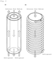
- a double-pipe heat exchanger as shown in Fig. 2(a) may be used as a heat exchanger.
- the external heat medium is allowed to flow from one side to the other through an inner pipe P1 of the double pipe (from upstream to downstream in Fig. 2(a) ), and the refrigerant is allowed to flow through an outer pipe P2 from the other side to the one side (from downstream to upstream in Fig. 2(a) ); this makes the flow of the refrigerant countercurrent with the flow of the external heat medium.
- a cylindrical pipe P3 wound with a spiral pipe P4 on its outer circumference as shown in Fig.
- the external heat medium is allowed to flow through the cylindrical pipe P3, for example, from one side to the other (from upstream to downstream in Fig. 2(b) ), and the refrigerant is allowed to flow through the spiral pipe P4 from the other side to the one side (from downstream to upstream in Fig. 2(b) ); this makes the flow of the refrigerant countercurrent with the flow of the external heat medium.
- known heat exchangers in which the refrigerant flows in the direction opposite to the flow of the external heat medium such as a plate heat exchanger (not shown), are also usable.
- a finned tube heat exchanger as shown in Fig. 3 may be used as a heat exchanger.
- the finned tube heat exchanger comprises a plurality of fins F that are arranged at a predetermined interval, and a heat transfer tube P5 that appears winding in a planar view.
- the heat transfer tube P5 is provided such that multiple straight portions (two portions in Fig. 3 ) of the heat transfer tube P5 that are in parallel to each other pass through the plurality of fins F.
- one end serves as an inlet for the refrigerant, and the other serves as an outlet for the refrigerant. Allowing a refrigerant to flow from downstream to upstream as indicated by arrow X in Fig. 3 in the direction of air flow Y makes the flow of the refrigerant countercurrent with the flow of the external heat medium.
- the refrigerant according to the present disclosure is a zeotropic composition, and the temperature of the heat medium increases or decreases during isobaric evaporation or condensation.
- a refrigeration cycle that involves temperature change (temperature glide) during evaporation or condensation is called a "Lorenz cycle.”
- Lorenz cycle when the evaporator and the condenser that function as a heat exchanger for exchanging heat are of countercurrent type, this decreases the difference in the temperature of the refrigerant between during evaporation and during condensation.
- a difference in temperature sufficiently large to effectively transfer heat between the refrigerant and the external heat medium is maintained, enabling efficient heat exchange.
- Another advantage of refrigerating machines equipped with a countercurrent heat exchanger is the minimum difference in pressure.
- a refrigerating machine (B) comprises a heat-source-side heat exchanger and a user-side heat exchanger, with the evaporating temperature of the refrigerant being 0°C or below when the user-side heat exchanger functions as an evaporator.
- the evaporating temperature of the refrigerant can be measured by detecting the temperature of the refrigerant at the outlet of the user-side heat exchanger.
- the heat exchanger of the refrigerating machine (B) does not have to be of countercurrent type.
- a refrigerating machine that has the characteristics of both the refrigerating machine (A) and the refrigerating machine (B) may be used.
- a refrigerating machine is usable that comprises a countercurrent heat exchanger in which the flow of the refrigerant and the flow of the external heat medium are in countercurrent flow, with the evaporating temperature of the refrigerant being 0°C or below when the heat exchanger functions as an evaporator.
- the refrigerating machine according to the present disclosure can be suitably used as a shipping refrigerating machine provided to shipping containers for overland or marine transport, or as a showcase refrigerating machine provided to refrigerating showcases or freezing showcases installed in shops.
- the refrigerating machines (A) and (B) may comprise a refrigerant circuit that includes a compressor, a heat-source-side heat exchanger, an expansion mechanism, and a user-side heat exchanger, in this order.
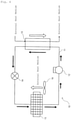
- Fig. 4 shows an embodiment of the refrigerant circuit in a refrigerating machine 10.
- a refrigerant circuit 11 mainly includes a compressor 12, a heat-source-side heat exchanger 13, an expansion mechanism 14, and a user-side heat exchanger 15; and is configured such that these devices 12 to 15 and other devices are sequentially connected.
- the refrigerant circuit 11 uses the mixture of fluorinated hydrocarbons described above as a refrigerant; the refrigerant circulates in the direction of the solid-line arrow in Fig. 4 .
- the compressor 12 is a device that compresses a low-pressure gas refrigerant, and ejects a high-temperature high-pressure gas refrigerant; the compressor 12 is installed in a space outside the machine, or in an outdoor space.
- the high-pressure gas refrigerant ejected from the compressor 12 is supplied to the heat-source-side heat exchanger 13.
- the heat-source-side heat exchanger 13 is a device that condenses (liquefies) the high-temperature high-pressure gas refrigerant compressed in the compressor 12; and is installed in a space outside the machine, or in an outdoor space.
- the high-pressure liquid refrigerant ejected from the heat-source-side heat exchanger 13 passes through the expansion mechanism 14.
- the expansion mechanism 14 is a device that depressurizes the high-pressure liquid refrigerant that released heat in the heat-source-side heat exchanger 13 to a low pressure in a refrigeration cycle; and is installed in a space inside the machine, or in an indoor space.
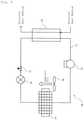
- the expansion mechanism 14 for use may be, for example, an electronic expansion valve; and is preferably a thermostatic expansion valve, as shown in Fig. 5 .
- a thermostatic expansion valve used as the expansion mechanism 14 detects the temperature of the refrigerant that has passed the user-side heat exchanger 15 by a thermostatic cylinder directly connected to the expansion valve, and controls the degree of opening of the expansion valve based on the detected refrigerant temperature.
- the user-side heat exchanger 15 is a device that evaporates (vaporizes) the low-pressure liquid refrigerant; and is installed in a space inside the machine, or in an indoor space.
- the low-pressure gas refrigerant ejected from the user-side heat exchanger 15 is supplied to the compressor 12, and recirculates the refrigerant circuit 11.
- the heat-source-side heat exchanger 13 functions as a condenser
- the user-side heat exchanger 15 functions as an evaporator
- two heat exchangers are of a countercurrent heat exchanger.
- the heat-source-side heat exchanger 13 is configured as a heat exchanger using water as an external heat medium (e.g., a double-pipe heat exchanger)
- the user-side heat exchanger 15 is configured as a heat exchanger using air as an external heat medium (e.g., a finned tube heat exchanger); however, the exchangers 13 and 15 are not limited to these exchangers.
- the heat-source-side heat exchanger 13 may be configured as a heat exchanger using air as an external heat medium
- the user-side heat exchanger 15 may be configured as a heat exchanger using water as an external heat medium.
- the heat-source-side heat exchanger 13 and the user-side heat exchanger 15 may both be configured as a heat exchanger using air as an external heat medium, or as a heat exchanger using water as an external heat medium.
- the evaporating temperature of the refrigerant is 0°C or below when the user-side heat exchanger 15 functions as an evaporator.
- the heat-source-side heat exchanger 13 and the user-side heat exchanger 15 do not have to be of countercurrent type.
- the refrigerant circuit 11 may have a plurality of expansion mechanisms 14 and a plurality of user-side heat exchangers 15 (two for each in Fig. 6 ) arranged in parallel.
- the refrigerant circuit 11 may further comprise a four-way switching valve 18 that switches the flow of the high-temperature high-pressure gas refrigerant compressed by the compressor 12 toward either the heat-source-side heat exchanger 13 or the user-side heat exchanger 15.
- the four-way switching valve 18 can switch the operation between the normal-cycle operation, in which the heat-source-side heat exchanger 13 functions as a radiator, while the user-side heat exchanger 15 functions as an evaporator (the direction of the solid-line arrow) and the reverse-cycle operation, in which the heat-source-side heat exchanger 13 functions as an evaporator, while the user-side heat exchanger 15 functions as a radiator (the direction of the dashed-line arrow).
- the user-side heat exchanger 15 may undergo frost formation.
- Frost formation decreases the heat-exchange efficiency of the user-side heat exchanger 15 (evaporator), increasing the power consumption and/or decreasing the cooling capacity.
- the defrosting operation may be off-cycle defrost performed by, as shown in Fig. 8 , stopping the operation of the compressor 12, and then activating a fan 16 without flowing the refrigerant to the user-side heat exchanger 15.
- the off-cycle defrost sends an external heat medium to the user-side heat exchanger 15 by the fan 16 to defrost the user-side heat exchanger 15.
- the user-side heat exchanger 15 configured with a heat exchanger that uses water as an external heat medium is provided with the fan 16.
- the defrosting operation may be heating defrost performed by, as shown in Fig. 9 , further adding a heating means 19 for heating the user-side heat exchanger 15 to the refrigerating machine 10, and activating the heating means 19.
- the heating defrost heats the user-side heat exchanger 15 by the heating means 19 to melt the frost adhered to the user-side heat exchanger 15, thereby defrosting the user-side heat exchanger 15.
- Examples of the heating means 19 for use include electric heaters.
- the defrosting operation may be reverse-cycle hot-gas defrost performed by, as shown in Fig. 10 , activating the reverse-cycle operation described above. Activating the reverse-cycle operation supplies the high-temperature high-pressure gas refrigerant compressed by the compressor 12 to the user-side heat exchanger 15 to melt the frost adhered to the user-side heat exchanger 15, thereby defrosting the user-side heat exchanger 15.
- the defrosting operation may be normal-cycle hot-gas defrost as shown in Fig. 11 .
- the refrigerant circuit 11 is provided with a bypass flow path 20 that is connected to the discharge side of the compressor 12 at one end, and to the inlet side of the user-side heat exchanger 15 at the other end.
- the normal-cycle hot-gas defrost opens a bypass valve 21, while circulating the refrigerant, to directly supply the high-temperature high-pressure gas refrigerant compressed by the compressor 12 to the user-side heat exchanger 15 through the bypass flow path 20. This melts the frost adhered to the user-side heat exchanger 15, thereby defrosting the user-side heat exchanger 15.
- the high-temperature high-pressure gas refrigerant compressed by the compressor 12 may be bypassed after being depressurized through the expansion mechanism 14 at the inlet side of the user-side heat exchanger 15.
- the predetermined conditions under which the defrosting operation (defrost) is performed may be configured such that, for example, a temperature sensor (not shown) detects the inflow refrigerant temperature at the user-side heat exchanger 15 and outside air temperature, and, for example, a control unit determines whether frost is formed in the user-side heat exchanger 15 based on these temperatures; and performs the defrosting operation (defrost) triggered by the determination that frost has been formed.
- a temperature sensor not shown
- the method for operating a refrigerating machine according to the present disclosure is a method for operating the refrigerating machine (A) or (B) using the refrigerant according to the present disclosure.
- the method for operating a refrigerating machine according to the present disclosure comprises circulating the refrigerant according to the present disclosure in the refrigerating machine (A) or (B).
- the method for operating a refrigerating machine may comprise switching the operation between a normal-cycle operation and a reverse-cycle operation by the four-way switching valve described below:
- the method for operating the refrigerating machine according to the present disclosure may further comprise performing reverse-cycle hot-gas defrost by the reverse-cycle operation.
- the method for operating a refrigerating machine may comprise performing off-cycle defrost by stopping the operation of the compressor described below, and operating the user-side fan described below:
- the method for operating a refrigerating machine may comprise performing heating defrost by heating the user-side heat exchanger with the heating means described below:
- a refrigerating machine comprising a refrigerant circuit that includes a compressor, a heat-source-side heat exchanger, an expansion mechanism, and a user-side heat exchanger in this order; and further comprising a heating means for heating the user-side heat exchanger.
- the method for operating a refrigerating machine may comprise performing normal-cycle hot-gas defrost by supplying a refrigerant compressed by the compressor to the user-side heat exchanger through the bypass flow path:
- a refrigerating machine comprising a refrigerant circuit that includes a bypass flow path that is connected to the discharge side of the compressor at one end, and to the inlet side of the user-side heat exchanger at the other end.
- the formulation of a mixed refrigerant composed only of R32, CO 2 , R125, R134a, and R1234yf is described as below. Specifically, the formulation of this mixed refrigerant is identified by coordinates (a,b,c) in a ternary composition diagram having R32 at a point of (100-x) mass%, CO 2 at a point of (100-x) mass%, and the sum of R125 and R134a at a point of (100-x) mass% as vertices, in which the mass% of R32 is a, the mass% of CO 2 is b, the mass% of R125 is c 1 , the mass% of R134a is c 2 , the mass% of the sum of R125 and R134a is c, the mass% of R1234yf is x, and c 1 / (c 1 +c 2 ) is r, based on the sum of R32, CO 2 , R125, R134a, and R1234yf.
- the non-flammability limit of a binary mixed refrigerant of a flammable refrigerant (R32 and 1234yf) and a non-flammable refrigerant (CO 2 , R134a, and R125) must be determined. How to determine the non-flammability limit of the binary mixed refrigerant is described below.
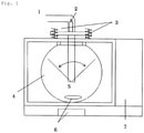
- the non-flammability limit of the binary mixed refrigerant was determined with the measurement device and measurement method of the combustion test according to ASTM E681-2009.
- a spherical glass flask (inner volume: 12 liters) was used.
- the upper lid of the glass flask was set to release gas when excessive pressure was applied on the glass flask by combustion.
- the ignition was initiated by discharge from electrodes held at a height one-third from the bottom. The test conditions are as described below.
- the test was performed on the combinations of a flammable refrigerant and a non-flammable refrigerant shown in Table 1.
- a non-flammable refrigerant was added to a flammable refrigerant in stages.
- This formulation was determined to be a non-flammability limit.
- Table 1 summarizes the results.
- Table 1 Item Flammable Refrigerant Non-Flammable Refrigerant Combination of Binary Mixed Refrigerant R32 R134a Non-Flammability Limit (wt%) 43.0 57.0 Combination of Binary Mixed Refrigerant R32 R125 Non-Flammability Limit (wt%) 63.0 37.0 Combination of Binary Mixed Refrigerant R32 CO 2 Non-Flammability Limit (wt%) 43.5 56.5 Combination of Binary Mixed Refrigerant 1234yf R134a Non-Flammability Limit (wt%) 62.0 38.0 Combination of Binary Mixed Refrigerant 1234yf R125 Non-Flammability Limit (wt%) 79.0 21.0 Combination of Binary Mixed Refrigerant 1234yf CO 2 Non-Flammability Limit (wt%) 63.0 37.0
- the R32 ⁇ converted flammable refrigerant concentration the concentration of R32 + the concentration of R1234yf ⁇ 21 / 79 ⁇ 63 / 37 + 38 / 62 + 43 / 57 / 2
- the R32 ⁇ converted non ⁇ flammable refrigerant concentration the concentration of R125 ⁇ 63 / 37 + the concentration of R134a ⁇ 43 / 57 the concentration of CO 2 43.5 / 56.5
- the ternary composition diagram of Fig. 1 shows the results of investigation of the calculated non-flammability limit formulations.
- the non-flammability limit of a mixed refrigerant determined from the non-flammability limit of a binary mixed refrigerant is considered to indicate the actual non-flammability limit.
- the ASHRAE non-flammability means that a mixed refrigerant becomes nonflammable in the most flammable formulation of the mixed refrigerant (WCF) and in the most flammable formulation under the worst conditions (WCFF) in a test for leakage in storage and transport, a test for leakage from equipment, and a test for leakage and refill conducted based on the WCF formulation.
- the WCFF concentrations were determined below by performing leakage simulations under various conditions with the NIST Standard Reference Database Refleak Version 4.0 ("Refleak" below).
- the pressure was atmospheric pressure at -40°C and at 52% release.
- the initial formulation takes (0.0, 39.5, 19.5 (4.9+14.6)) as the WCF formulation, both the WCF formulation and the WCFF formulation are determined to be non-flammable in calculation.
- Table 8 shows the results of the study performed in the same manner as above.
- Table 9 shows the results of the study performed in the same manner as above.
- individual non-flammability limits are determined by this method below.
- Line segment ABr is defined as the WCF non-flammability limit line
- line segment FrPr is defined as the ASHRAE non-flammability limit line.
- Tables 10 to 13 show the WCF non-flammability limit points of mixed refrigerants determined from the non-flammability limit of binary mixed refrigerants.
- Tables 14 to 17 show the ASHRAE non-flammability limit points determined from the leakage simulation and the non-flammability limits of binary mixed refrigerants.
- compositions each containing R410A and a mixture of R32, R125, R1234yf, R134a, and CO 2 was evaluated based on the values stated in the Fourth Assessment Report of the Intergovernmental Panel on Climate Change (IPCC).
- IPCC Intergovernmental Panel on Climate Change
- the refrigerating capacity of compositions each containing R410A and a mixture of R410A, R32, R125, R1234yf, R134a, and CO 2 was determined by performing theoretical refrigeration cycle calculations for the mixed refrigerants using the National Institute of Science and Technology (NIST) and Reference Fluid Thermodynamic and Transport Properties Database (Refprop 9.0) under the following conditions.
- Tables 18 to 30 show GWP, COP, refrigerating capacity, and condensation glide (condensation temperature glide), which were calculated based on these results.
- the COP and refrigerating capacity are percentages relative to R410A.
- COP coefficient of performance
Landscapes
- Engineering & Computer Science (AREA)
- Chemical & Material Sciences (AREA)
- Physics & Mathematics (AREA)
- Thermal Sciences (AREA)
- Chemical Kinetics & Catalysis (AREA)
- Mechanical Engineering (AREA)
- General Engineering & Computer Science (AREA)
- Combustion & Propulsion (AREA)
- Materials Engineering (AREA)
- Organic Chemistry (AREA)
- Lubricants (AREA)
Abstract
Description
- The present disclosure relates to a refrigerant containing a fluorinated hydrocarbon and carbon dioxide, use of the refrigerant, a refrigerating machine containing the refrigerant, and a method for operating the refrigerating machine.
- Fluorocarbon-based fluids are widely used industrially for cooling, air conditioning, and heat pumps.
-
PTL 1 discloses the use of a heat transfer composition containing difluoromethane (R32), 1,1,1,3-tetrafluoropropene (R1234ze), and a compound selected from the group consisting of n-butane, isobutane, and combinations thereof in a specific mixture ratio as an alternative for R410A and/or R32. -
PTL 2 discloses the use of a working fluid for heat cycle containing trifluoroethylene (HFO-1123), 2,3,3,3-tetrafluoropropene (R1234yf), and difluoromethane (R32) in a specific mixture ratio as an alternative for R410A. -
PTL 3 discloses the use of a composition containing R1234yf, R32, pentafluoroethane (R125), and 1,1,1,2-tetrafluoroethane (R134a) in a specific mixture ratio as a refrigerant with a lower GWP that replaces R22, R134a, R404A, R407C, and/or R410A. -
PTL 4 discloses the use of a heat transfer composition containing R32, R125, R134a, and R1234yf in a specific mixture ratio as an alternative refrigerant for R134a, R410A, or R404A. -
- PTL 1:
WO2014/085973A - PTL 2:
JP2016-028119A - PTL 3:
WO2010/059677A - PTL 4:
WO2011/163117A - The present inventors conceived that a refrigerant composition that has a COP and a refrigerating capacity equivalent to those of R410A and a low GWP, as well as ASHRAE non-flammability, had not yet been developed in the art. They conducted studies and determined the desired properties of an alternative refrigerant for R410A on their own accord. The following are the desired properties: (1) a GWP of 750 or less, (2) WCF non-flammability or ASHRAE non-flammability, and (3) a COP and refrigerating capacity equivalent to those of R410A. An object of the present disclosure is to solve this unique problem.
- The present inventors conducted extensive research to solve the problem, and found that a mixed refrigerant that contains difluoromethane (R32), carbon dioxide (CO2), pentafluoroethane (R125), 1,1,1,2-tetrafluoroethane (R134a), and 2,3,3,3-tetrafluoropropene (R1234yf) in predetermined proportions has the properties described above.
- After conducting further research based on this finding, the inventors completed the present disclosure. The present disclosure includes the following embodiments.
-
Item 1. A composition comprising a refrigerant, - the refrigerant comprising difluoromethane (R32), carbon dioxide (CO2), pentafluoroethane (R125), 1,1,1,2-tetrafluoroethane (R134a), and 2,3,3,3-tetrafluoropropene (R1234yf),
wherein - when the mass% of R32 is a, the mass% of CO2 is b, the mass% of R125 is c1, the mass% of R134a is c2, the mass% of the sum of R125 and R134a is c, the mass% of R1234yf is x, and c1/ (c1+c2) is r based on the sum of R32, CO2, R125, R134a, and R1234yf in the refrigerant,
- in a ternary composition diagram having R32 at a point of (100-x) mass%, CO2 at a point of (100-x) mass%, and the sum of R125 and R134a at a point of (100-x) mass% as vertices,
- 1-1-1) when 43.8≥x≥41, and 0.5≥r≥0.25, coordinates (a,b,c) fall within a quadrangular region surrounded by line segments that connect the following points:
- point A (-0.6902x+43.307, 100-a-x, 0.0),
- point Or=0.25 to 0.5 ((-2.2857x+87.314) r2+ (1.7143x-55.886) r+ (-0.9643x+55.336), (2.2857x-112.91) r2+ (-1.7143x+104.69) r+ (-0.25x+11.05), 100-a-b-x),
- point Dr=0.25 to 0.5 (0.0, -28.8r2+54.0r+ (-x+49.9) , 100-b-x) , and
- point Q (0.0, 100-x, 0.0),
- or on the line segments, excluding any point on line segment Dr=0.25 to 0.5 to Q, and line segment QA, or
- 1-1-2) when 43.8≥x≥41, and 1.0≥r≥0.5, coordinates (a,b,c) fall within a quadrangular region surrounded by line segments that connect the following points:
- point A (-0.6902x+43.307, 100-a-x, 0.0),
- point Or=0.5 to 1.0 ((-0.2857x+8.5143) r2+ (0.5x-10.9) r+ (-0.8571x+52.543), (-0.2857x+4.5143) r2+ (0.5x+0.9) r+ (-0.7143x+33.586), 100-a-b-x),
- point Dr=0.5 to 1.0 (0.0, (-0.5714x+12.229) r2+ (0.8571x-0.3429) r+ (-1.2857x+66.814), 100-b-x), and
- point Q (0.0, 100-x, 0.0),
- or on the line segments, excluding any point on line segment Dr=0.5 to 1.0 to Q and line segment QA,
- or on the line segments, or
- 1-2-1) when 46.5≥x≥43.8, and 0.5≥r≥0.25, coordinates (a,b,c) fall within a quadrangular region surrounded by line segments that connect the following points:
- point A (-0.6902x+43.307, 100-a-x, 0.0),
- point Or=0.25 to 0.5 ((1.1852x-64.711) r2+ (-0.7407x+51.644) r+ (-0.5556x+37.433), (-2.3704x+91.022) r2+ (2.0741x-61.244) r+ (-0.963x+42.278), 100-a-b-x),
- point Dr=0.25 to 0.5 (0.0, -28.8r2+54.0r+ (-x+49.9) , 100-b-x), and
- point Q (0.0, 100-x, 0.0),
- or on the line segments, excluding any point on line segment Dr=0.25 to 0.5 to Q and line segment QA, or
- 1-2-2) when 46.5≥x≥43, and 1.0≥r≥0.5, coordinates (a,b,c) fall within a quadrangular region surrounded by line segments that connect the following points:
- point A (-0.6902x+43.307, 100-a-x, 0.0),
- point Or-0.5 to 1.0 ((0.2963x-16.978) r2+ (-0.3704x+27.222) r+ (-0.5185x+37.711), -8.0r2+22.8r+(-0.5185x+25.011), 100-a-b-x),
- point Dr=0.5 to 1.0 (0.0, -12.8r2+37.2r+ (-x+54.3) , 100-b-x), and
- point Q (0.0, 100-x, 0.0),
- or on the line segments, excluding any point on line segment Dr=0.5 to 1.0 to Q and line segment QA,
- 1-3-1) when 50≥x≥46.5, and 0.5≥r≥0.25, coordinates (a,b,c) fall within a quadrangular region surrounded by line segments that connect the following points:
- point A (-0.6902x+43.307, 100-a-x, 0.0),
- point Or=0.25 to 0.5 (-9.6r2+17.2r+ (-0.6571x+42.157) ,-19.2r2+(0.2286x+24.571)r+(-0.6286x+26.729), 100-a-b-x),
- point Dr=0.25 to 0.5 (0.0, (0.9143x-71.314) r2+ (-0.5714x+80.571) r+ (-0.9143x+45.914), 100-b-x), and
- point Q (0.0, 100-x, 0.0),
- or on the line segments, excluding any point on line segment Dr=0.25 to 0.5 to Q and line segment QA, or
- 1-3-2) when 50≥x≥46.5, and 1.0≥r≥0.5, coordinates (a,b,c) fall within a quadrangular region surrounded by line segments that connect the following points:
- point A (-0.6902x+43.307, 100-a-x, 0.0),
- point Or=0.5 to 1.0 ( (-0.2286x+7.4286) r2+ (0.4x-8.6) r+ (-0.8x+50.8),
- (0.2286x-18.629) r2+ (-0.2857x+36.086) r+ (-0.4286x+20.829), 100-a-b-x),
- point Dr=0.5 to 1.0 (0.0, (0.2286x-23.429) r2+ (-0.4x+55.8) r+ (-0.8286x+46.329), 100-b-x), and
- point Q (0.0, 100-x, 0.0),
- or on the line segments, excluding any point on line segment Dr=0.5 to 1.0 to Q and line segment QA.
-
Item 2. A composition comprising a refrigerant, - the refrigerant comprising R32, CO2, R125, R134a, and R1234yf,
wherein - when the mass% of R32 is a, the mass% of CO2 is b, the mass% of R125 is c1, the mass% of R134a is c2, the mass% of the sum of R125 and R134a is c, the mass% of R1234yf is x, and c1/ (c1+c2) is r based on the sum of R32, CO2, R125, R134a, and R1234yf in the refrigerant,
- in a ternary composition diagram having R32 at a point of (100-x) mass%, CO2 at a point of (100-x) mass%, and the sum of R125 and R134a at a point of (100-x) mass% as vertices,
- 2-1-1) when 43.8≥x≥41, and 0.5≥r≥0.25, coordinates (a,b,c) fall within a triangular region surrounded by line segments that connect the following points:
- point Fr=0.25 to 0.5 (0.0, (-1.1429x+37.257) r2+ (1.2857x-38.714) r- (-1.7143x+106.89), 100-b-x),
- point Pr=0.25 to 0.5 ((-1.1429x+34.057) r2+ (1.0x-21.0) r+ (-0.4643x+27.636), (2.2857x-119.31) r2+ (-2.0x+122.0) r+ (-0.3929x+19.907), 100-a-b-x), and
- point Dr=0.25 to 0.5 (0.0, -28.8r2+54.0r+ (-x+49.9), 100-b-x) ,
- or on the line segments, excluding any point on line segment Dr=0.25 to 0.5 to Fr=0.25 to 0.5, or
- 2-1-2) when 43.8≥x≥41, and 1.0≥r≥0.5, coordinates (a,b,c) fall within a triangular region surrounded by line segments that connect the following points:
- point Fr=0.5 to 1.0 (0.0, (3.7143x-159.49) r2+ (-5.0714x+222.53)r+(0.25x+25.45), 100-b-x),
- point Pr=0.5 to 1.0 ((3.4286x-138 .17) r2+ (-5.4286x+203.57) r+ (1.6071x-41.593), (-2.8571x+106.74) r2+ (4.5714x-143.63) r+ (-2.3929x+96.027), 100-a-b-x), and
- point Dr=0.5 to 1.0 (0.0, (-0. 5714x+12 .229) r2+ (0.8571x-0.3429) r+ (-1.2857x+66.814), 100-b-x),
- or on the line segments, excluding any point on line segment Dr=0.5 to 1.0 to Fr=0.5 to 1.0, or
- 2-2-1) when 46.5≥x≥43, and 0.5≥r≥0.25, coordinates (a,b,c) fall within a triangular region surrounded by line segments that connect the following points:
- point Fr=0.25 to 0.5 (0.0, (9.4815x-428.09) r2+ (-7.1111x+329.07) r+ (-0.2593x+43.156), 100-b-x),
- point Pr=0.25 to 0.5 ((-8.2963x+347.38) r2+ (4.8889x-191.33) r+ (-0.963x+49.478), (7.1111x-330.67) r2+ (-4.1481x+216.09) r+ (-0.2593x+14.056), 100-a-b-x), and
- point Dr=0.25 to 0.5 (0.0, -28.8r2+54.0r+ (-x+49.9), 100-b-x),
- or on the line segments, excluding any point on line segment Dr=0.25 to 0.5 to Fr=0.25 to 0.5, or
- 2-2-2) when 46.5≥x≥43, and 1.0≥r≥0.5, coordinates (a,b,c) fall within a triangular region surrounded by line segments that connect the following points:
- point Fr=0.5 to 1.0 (0.0, (-4.7407x+210.84) r2+ (6.963x-304.58) r+ (-3.7407x+200.24), 100-b-x),
- point Pr=0.5 to 1.0 ((0.2963x-0.9778) r2+ (0.2222x-43.933) r+ (-0.7778x+62.867), (-0.2963x-5.4222) r2+ (-0.0741x+59.844) r+ (-0.4444x+10.867), 100-a-b-x), and
- point Dr=0.5 to 1.0 (0.0, -12.8r2+37.2r+ (-x+54.3) , 100-b-x),
- or on the line segments, excluding any point on line segment Dr=0.5 to 1.0 to Fr=0.5 to 1.0, or
- 2-3-1) when 50≥x≥46.5, and 0.37≥r≥0.25, coordinates (a,b,c) fall within a triangular region surrounded by line segments that connect the following points:
- point Fr=0.25 to 0.37 (0.0, (-35.714x+1744.0) r2+ (23.333x-1128.3) r+ (-5.144x+276.32), 100-b-x),
- point Pr=0.25 to 0.37 ((11.905x-595.24) r2+ (-7.6189x+392.61) r+ (0.9322x-39.027), (-27.778x+1305.6) r2+ (17.46x-796.35) r+ (-3.5147x+166.48), 100-a-b-x), and
- point Dr=0.25 to 0.37 (0.0), (0.9143x-71.314) r2+ (-0.5714x+80.571) r+ (-0.9143x+45.914), 100-b-x),
- or on the line segments, excluding any point on line segment Dr=0.25 to 0.37 to Fr=0.25 to 0.37, or
- 2-3-2) when 50≥x≥46.5, and 1.0≥r≥0.5, coordinates (a,b,c) fall within a triangular region surrounded by line segments that connect the following points:
- point Fr=0.5 to 1.0 (0.0, (2.2857x-115.89) r2+ (-3.0857x+162.69) r+ (-0.3714x+43.571), 100-b-x),
- point Pr=0.5 to 1.0 ((-3.2x+161.6) r2+ (4.4571x-240.86) r+ (-2.0857x+123.69), (2.5143x-136.11) r2+ (-3.3714x+213.17) r+ (0.5429x-35.043), 100-a-b-x), and
- point Dr=0.5 to 1.0 (0.0, (0.2286x-23.429) r2+ (-0.4x+55.8) r+ (-0.8286x+46.329), 100-b-x),
- or on the line segments, excluding any point on line segment Dr=0.5 to 1.0 to Fr=0.5 to 1.0.
-
Item 3. The composition according toItem -
Item 4. The composition according to any one ofItems 1 to 3, comprising a refrigeration oil. -
Item 5. The composition according to any one ofItems 1 to 4, wherein the refrigerant is for use as an alternative refrigerant for R410A. -
Item 6. A refrigerating machine comprising the composition of any one ofItems 1 to 5. -
Item 7. The refrigerating machine according toItem 6, comprising a heat exchanger in which a flow of the refrigerant and a flow of an external heat medium are in countercurrent flow. - Item 8. The refrigerating machine according to
Item -
Item 9. A refrigerating machine comprising - a refrigerant comprising R32, CO2, R125, R134a, and R1234yf, and
- a heat exchanger in which a flow of the refrigerant and a flow of an external heat medium are in countercurrent flow.
-
Item 10. A refrigerating machine comprising - a refrigerant comprising R32, CO2, R125, R134a, and R1234yf,
- a heat-source-side heat exchanger, and
- a user-side heat exchanger,
wherein when the user-side heat exchanger functions as an evaporator, the evaporating temperature of the refrigerant is 0°C or below. - The refrigerant according to the present disclosure has the following properties, which are typically required in alternative refrigerants for R410A: (1) a GWP of 750 or less, (2) WCF non-flammability or ASHRAE non-flammability, and (3) a COP and a refrigerating capacity equivalent to those of R410A.
-
-
Fig. 1 is a diagram that shows a device used in a flammability test. -
Fig. 2 is a schematic view that shows examples of countercurrent heat exchangers. -
Fig. 3 is a schematic view that shows examples of countercurrent heat exchangers.Fig. 3(a) is a plan view, andFig. 3(b) is a perspective view. -
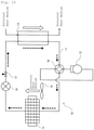
Fig. 4 is a schematic view that shows an embodiment of refrigerant circuits in the refrigerating machine according to the present disclosure. -
Fig. 5 is a schematic view that shows an example of modified versions of the refrigerant circuit ofFig. 4 . -
Fig. 6 is a schematic view that shows an example of modified versions of the refrigerant circuit ofFig. 5 . -
Fig. 7 is a schematic view that shows an example of modified versions of the refrigerant circuit ofFig. 5 . -
Fig. 8 is a schematic view that explains off-cycle defrost. -
Fig. 9 is a schematic view that explains heating defrost. -
Fig. 10 is a schematic view that explains reverse-cycle hot-gas defrost. -
Fig. 11 is a schematic view that explains normal-cycle hot-gas defrost. -
Fig. 12 shows a straight line Cr=0.25 to Dr=0.25 that shows GWP is 750, the WCF non-flammability limit points shown in Tables 2 to 5, a straight line ABr=0.25, which connects point A and point Br=0.25, the ASHRAE non-flammability limit points shown in Tables 6 to 9, and a straight line Fr=0.25 to Pr=0.25, which connects point Fr=0.25 and point Pr=0.25, when r=0.25 in a ternary composition diagram having R32 at a point of (100-x) mass%, CO2 at a point of (100-x) mass%, and the sum of R125 and R134a at a point of (100-x) mass% as vertices. -
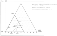
Fig. 13 shows a straight line Cr=0.375 to Dr=0.375 that shows GWP is 750, a straight line ABr=0.375 that shows the WCF non-flammability limit line shown in Table 10, and a straight line Fr=0.375 to Pr=0.375 that shows the ASHRAE non-flammability limit line shown in Table 14, when r=0.375, in a ternary composition diagram having R32 at a point of (100-x) mass%, CO2 at a point of (100-x) mass%, and the sum of R125 and R134a at a point of (100-x) mass% as vertices. -
Fig. 14 shows a straight line Cr=0.5 to Dr=0.5 that shows GWP is 750, a straight line ABr=0.5 that shows the WCF non-flammability limit shown in Table 10, a straight line Fr=0.5 to Pr=0.5 that shows the ASHRAE non-flammability limit shown in Table 14, when r=0.5, in a ternary composition diagram having R32 at a point of (100-x) mass%, CO2 at a point of (100-x) mass%, and the sum of R125 and R134a at a point of (100-x) mass% as vertices. -
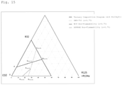
Fig. 15 shows a straight line Cr=0.75 to Dr=0.75 that shows GWP is 750, a straight line ABr=0.75 that shows the WCF non-flammability limit shown in Table 10, and a straight line Fr=0.75 to Pr=0.75 that shows the ASHRAE non-flammability limit shown in Table 14, when r=0.75, in a ternary composition diagram having R32 at a point of (100-x) mass%, CO2 at a point of (100-x) mass%, and the sum of R125 and R134a at a point of (100-x) mass% as vertices. -
Fig. 16 shows a straight line Cr=1.0 to Dr=1.0 that shows GWP is 750, a straight line ABr=1.0 that shows the WCF non-flammability limit shown in Table 10, and a straight line Fr=1.0 to Pr=1.0 that shows the ASHRAE non-flammability limit shown in Table 14, when r=1.0, in a ternary composition diagram having R32 at a point of (100-x) mass%, CO2 at a point of (100-x) mass%, and the sum of R125 and R134a at a point of (100-x) mass% as vertices. -
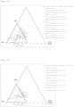
Fig. 17 is a ternary diagram that summarizesFigs. 12 to 16 and that shows points A, Or=0.25 to 1, Dr=0.25 to 1, Cr=0.25 to 1, Fr=0.25 to 1, Pr=0.25 to 1, and Q when the concentration of R1234yf is 41 mass%. -
Fig. 18 is a ternary diagram that shows points A, Or=0.25 to 1, Dr=0.25 to 1, Cr=0.25 to 1, Fr=0.25 to 1, Pr=0.25 to 1, and Q when the concentration of R1234yf is 43.8 mass%. -
Fig. 19 is a ternary diagram that shows points A, Or=0.25 to 1, Dr=0.25 to 1, Cr=0.25 to 1, Fr=0.25 to 1, Pr=0.25 to 1, and Q, when the concentration of R1234yf is 46.5 mass%. -
Fig. 20 is a ternary diagram that shows points A, Or=0.25 to 1, Dr=0.25 to 1, Cr=0.25 to 1, Pr=0.25 to 1, and Q when the concentration of R1234yf is 50.0 mass%. -
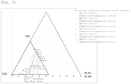
Fig. 21 is a ternary diagram that shows points Dr=0.25 to 1, Cr=0.25 to 1, Fr=0.25 to 0.37, Fr=0.5 to 1, Pr=0.25 to 0.37, Pr=0.50 to 1, and Q when the concentration of R1234yf is 46.5 mass%. -
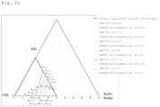
Fig. 22 is a ternary diagram that shows points Dr=0.25 to 1, Cr=0.25 to 1, Fr=0.25 to 0.37, Fr=0.37 to 1, Pr=0.25 to 0.37, Pr=0.37 to 1, and Q when the concentration of R1234yf is 50.0 mass%. - In the present specification, the term "refrigerant" includes at least compounds that are specified in ISO 817 (International Organization for Standardization), and that are given a refrigerant number (ASHRAE number) representing the type of refrigerant with "R" at the beginning; and further includes refrigerants that have properties equivalent to those of such refrigerants, even though a refrigerant number is not yet given. Refrigerants are broadly divided into fluorocarbon compounds and non-fluorocarbon compounds in terms of the structure of the compounds. Fluorocarbon compounds include chlorofluorocarbons (CFC), hydrochlorofluorocarbons (HCFC), and hydrofluorocarbons (HFC). Non-fluorocarbon compounds include propane (R290), propylene (R1270), butane (R600), isobutane (R600a), carbon dioxide (R744), ammonia (R717), and the like.
- In the present specification, the phrase "composition comprising a refrigerant" at least includes (1) a refrigerant itself (including a mixture of refrigerants), (2) a composition that further comprises other components and that can be mixed with at least a refrigeration oil to obtain a working fluid for a refrigerating machine, and (3) a working fluid for a refrigerating machine containing a refrigeration oil. In the present specification, of these three embodiments, the composition (2) is referred to as a "refrigerant composition" so as to distinguish it from a refrigerant itself (including a mixture of refrigerants). Further, the working fluid for a refrigerating machine (3) is referred to as a "refrigeration oil-containing working fluid" so as to distinguish it from the "refrigerant composition."
- In the present specification, when the term "alternative" is used in a context in which the first refrigerant is replaced with the second refrigerant, the first type of "alternative" means that equipment designed for operation using the first refrigerant can be operated using the second refrigerant under optimum conditions, optionally with changes of only a few parts (at least one of the following: refrigeration oil, gasket, packing, expansion valve, dryer, and other parts) and equipment adjustment. In other words, this type of alternative means that the same equipment is operated with an alternative refrigerant. Embodiments of this type of "alternative" include "drop-in alternative," "nearly drop-in alternative," and "retrofit," in the order in which the extent of changes and adjustment necessary for replacing the first refrigerant with the second refrigerant is smaller.
- The term "alternative" also includes a second type of "alternative," which means that equipment designed for operation using the second refrigerant is operated for the same use as the existing use with the first refrigerant by using the second refrigerant. This type of alternative means that the same use is achieved with an alternative refrigerant.
- In the present specification, the term "refrigerating machine" refers to machines in general that draw heat from an object or space to make its temperature lower than the temperature of ambient air, and maintain a low temperature. In other words, refrigerating machines refer to conversion machines that gain energy from the outside to do work, and that perform energy conversion, in order to transfer heat from where the temperature is lower to where the temperature is higher.
- In the present disclosure, "non-flammability" means that the WCF (worst case of formulation for flammability) formulation, which is the most flammable formulation within the refrigerant's allowable concentrations in the U.S. ANSI/ASHRAE 34-2013 Standard, is categorized into Class 1 (i.e., WCF non-flammability) or determined to be ASHRAE non-flammability. Specifically, ASHRAE non-flammability means that the WCF formulation or WCFF formulation can be identified as nonflammable in a test performed with the measurement equipment and the method in accordance with ASTM E681-2009 Standard Test Method for Concentration Limits of Flammability of Chemicals (Vapors and Gases), and the WCF formulation and WCFF formulation are each classified as
Class 1 ASHRAE non-flammability (WCF non-flammability) orClass 1 ASHRAE non-flammability (WCFF non-flammability). The WCFF formulation (worst case of fractionation for flammability: most flammable formulation) is determined by conducting a test for leakage in storage, transport, and use in accordance with ANSI/ASHRAE 34-2013. - The refrigerant according to the present disclosure is a mixed refrigerant comprising R32, CO2, R125, R134a, and R1234yf.
- The refrigerant according to the present disclosure has the following properties that are typically required for alternative refrigerants for R410A: (1) a GWP of 750 or less, (2) WCF non-flammability or ASHRAE non-flammability, and (3) a COP and a refrigerating capacity equivalent to those of R410A.
- In addition to the properties described above, the refrigerant according to the present disclosure, due to its temperature glide, can also have effects in improving energy efficiency and/or refrigerating capacity when used in a refrigerating machine equipped with a heat exchanger in which the flow of the refrigerant and the flow of the external heat medium are in countercurrent flow.
- The refrigerant according to the present disclosure that satisfies the following requirements 1-1-1 to 1-3-2 is preferable, because such a refrigerant has a GWP of 750 or less, and WCF non-flammability. In the description below, the mass% of R32 is a, the mass% of CO2 is b, the mass% of R125 is c1, the mass% of R134a is c2, the mass% of the sum of R125 and R134a is c, the mass% of R1234yf is x, and c1/ (c1+c2) is r, based on the sum of R32, CO2, R125, R134a, and R1234yf.
- In a ternary composition diagram having R32 at a point of (100-x) mass%, CO2 at a point of (100-x) mass%, and the sum of R125 and R134a at a point of (100-x) mass% as vertices, coordinates (a,b,c) are as defined below:
- When 43.8≥x≥41, and 0.5≥r≥0.25, coordinates (a,b,c) fall within a quadrangular region surrounded by line segments that connect the following points:
- point A (-0.6902x+43.307, 100-a-x, 0.0),
- point Or=0.25 to 0.5 ((-2.2857x+87.314) r2+ (1.7143x-55.886) r+ (-0.9643x+55.336), (2.2857x-112.91) r2+ (-1.7143x+104.69) r+ (-0.25x+11.05), 100-a-b-x),
- point Dr=0.25 to 0.5 (0.0, -28.8r2+54.0r+ (-x+49.9), 100-b-x), and point Q (0.0, 100-x, 0.0),
- or on the line segments, excluding any point on line segment Dr=0.25 to 0.5 to Q, and line segment QA, or
- When 43.8≥x≥41, and 1.0≥r≥0.5, coordinates (a,b,c) fall within a quadrangular region surrounded by line segments that connect the following points:
- point A (-0.6902x+43.307, 100-a-x, 0.0),
- point Or=0.5 to 1.0 ((-0.2857x+8.5143) r2+ (0.5x-10.9) r+ (-0.8571x+52.543), (-0.2857x+4.5143) r2+ (0.5x+0.9) r+ (-0.7143x+33.586), 100-a-b-x),
- point Dr=0.5 to 1.0 (0.0, (-0.5714x+12 .229) r2+ (0.8571x-0.3429) r+ (-1.2857x+66.814), 100-b-x), and
- point Q (0.0, 100-x, 0.0),
- or on the line segments, excluding any point on line segment Dr=0.5 to 1.0 to Q, and line segment QA, or
- when 46.5≥x≥43.8, and 0.5≥r≥0.25, coordinates (a,b,c) fall within a quadrangular region surrounded by line segments that connect the following points:
- point A (-0.6902x+43.307, 100-a-x, 0.0),
- point Or=0.25 to 0.5 ((1.1852x-64.711) r2+ (-0.7407x+51.644) r+ (-0.5556x+37.433), (-2.3704x+91.022) r2+ (2.0741x-61.244) r+ (-0.963x+42.278), 100-a-b-x),
- point Dr=0.25 to 0.5 (0.0, -28.8r2+54.0r+ (-x+49.9), 100-b-x), and point Q (0.0, 100-x, 0.0),
- or on the line segments, excluding any point on line segment Dr=0.25 to 0.5 to Q, and line segment QA, or
- When 46.5≥x≥43, and 1.0≥r≥0.5, coordinates (a,b,c) fall within a quadrangular region surrounded by line segments that connect the following points:
- point A (-0.6902x+43.307, 100-a-x, 0.0),
- point Or=0.5 to 1.0 ((0.2963x-16.978) r2+ (-0.3704x+27.222) r+ (-0.5185x+37.711), -8.0r2+22.8r+(-0.5185x+25.011), 100-a-b-x), point Dr=0.5 to 1.0 (0.0, -12.8r2+37.2r+ (-x+54.3) , 100-b-x), and point Q (0.0, 100-x, 0.0),
- or on the line segments, excluding any point on line segment Dr=0.5 to 1.0 to Q and line segment QA,
- When 50≥x≥46.5, and 0.5≥r≥0.25, coordinates (a,b,c) fall within a quadrangular region surrounded by line segments that connect the following points:
- point A (-0.6902x+43.307, 100-a-x, 0.0),
- point Or=0.25 to 0.5 (-9.6r2+17.2r+ (-0.6571x+42.157),-19.2r2+ (0.2286x+24.571) r+ (-0.6286x+26.729), 100-a-b-x),
- point Dr=0.25 to 0.5 (0.0, (0.9143x-71.314) r2+ (-0.5714x+80.571) r+ (-0.9143x+45.914), 100-b-x), and
- point Q (0.0, 100-x, 0.0),
- or on the line segments, excluding any point on line segment Dr=0.25 to 0.5 to Q and line segment QA, or
- When 50≥x≥46.5, and 1.0≥r≥0.5, coordinates (a,b,c) fall within a quadrangular region surrounded by line segments that connect the following points:
- point A (-0.6902x+43.307, 100-a-x, 0.0),
- point Or=0.5 to 1.0 ((-0.2286x+7.4286) r2+ (0.4x-8.6) r+ (-0.8x+50.8), (0.2286x-18.629) r2+ (-0.2857x+36.086) r+ (-0.4286x+20.829), 100-a-b-x),
- point Dr=0.5 to 1.0 (0.0, (0.2286x-23.429) r2+ (-0.4x+55.8) r+ (-0.8286x+46.329), 100-b-x), and
- point Q (0.0, 100-x, 0.0),
- or on the line segments, excluding any point on line segment Dr=0.5 to 1.0 to Q and line segment QA.
- The refrigerant according to the present disclosure that satisfies the following requirements 2-1-1 to 2-3-2 is preferable, because such a refrigerant has a GWP of 750 or less, and ASHRAE non-flammability.
- When 43.8≥x≥41, and 0.5≥r≥0.25, coordinates (a,b,c) fall within a triangular region surrounded by line segments that connect the following points:
- point Fr=0.25 to 0.5 (0.0, (-1.1429x+37.257) r2+ (1.2857x-38.714) r- (-1.7143x+106.89), 100-b-x),
- point Pr=0.25 to 0.5 ((-1.1429x+34.057) r2+ (1.0x-21.0) r+ (-0.4643x+27.636), (2.2857x-119.31) r2+ (-2.Ox+122.0) r+ (-0.3929x+19.907), 100-a-b-x), and
- point Dr=0.25 to 0.5 (0.0, -28.8r2+54.0r+ (-x+49.9), 100-b-x),
- or on the line segments, excluding any point on line segment Dr=0.25 to 0.5 to Fr=0.25 to 0.5, or
- When 43.8≥x≥41, and 1.0≥r≥0.5, coordinates (a,b,c) fall within a triangular region surrounded by line segments that connect the following points:
- point Fr=0.5 to 1.0 (0.0, (3.7143x-159.49) r2+ (-5.0714x+222.53)r+(0.25x+25.45), 100-b-x),
- point Pr=0.5 to 1.0 ((3.4286x-138.17) r2+ (-5.4286x+203.57) r+ (1.6071x-41.593), (-2.8571x+106.74) r2+ (4.5714x-143.63) r+ (-2.3929x+96.027), 100-a-b-x), and
- point Dr=0.5 to 1.0 (0.0, (-0. 5714x+12 .229) r2+ (0.8571x-0.3429) r+ (-1.2857x+66.814), 100-b-x),
- or on the line segments, excluding any point on line segment Dr=0.5 to 1.0 to Fr=0.5 to 1.0, or
- When 46.5≥x≥43, and 0.5≥r≥0.25, coordinates (a,b,c) fall within a triangular region surrounded by line segments that connect the following points:
- point Fr=0.25 to 0.5 (0.0, (9.4815x-428.09) r2+ (-7.1111x+329.07) r+ (-0.2593x+43.156), 100-b-x),
- point Pr=0.25 to 0.5 ((-8.2963x+347.38) r2+ (4.8889x-191.33) r+ (-0.963x+49.478), (7.1111x-330.67) r2+ (-4.1481x+216.09) r+ (-0.2593x+14.056), 100-a-b-x), and
- point Dr=0.25 to 0.5 (0.0, -28.8r2+54.0r+ (-x+49.9), 100-b-x),
- or on the line segments, excluding any point on line segment Dr=0.25 to 0.5 to Fr=0.25 to 0.5, or
- When 46.5≥x≥43, and 1.0≥r≥0.5, coordinates (a,b,c) fall within a triangular region surrounded by line segments that connect the following points:
- point Fr=0.5 to 1.0 (0.0, (-4.7407x+210.84) r2+ (6.963x-304.58) r+ (-3.7407x+200.24), 100-b-x),
- point Pr=0.5 to 1.0 ((0.2963x-0.9778) r2+ (0.2222x-43.933) r+ (-0.7778x+62.867), (-0.2963x-5.4222) r2+ (-0.0)741x+59.844) r+ (-0.4444x+10.867), 100-a-b-x), and
- point Dr=0.5 to 1.0 (0.0, -12.8r2+37.2r+ (-x+54.3), 100-b-x),
- or on the line segments, excluding any point on line segment Dr=0.5 to 1.0 to Fr=0.5to 1.0, or
- When 50≥x≥46.5, and 0.37≥r≥0.25, coordinates (a,b,c) fall within a triangular region surrounded by line segments that connect the following points:
- point Fr=0.25 to 0.37 (0.0, (-35.714x+1744.0) r2+ (23.333x-1128.3) r+ (-5.144x+276.32), 100-b-x),
- point Pr=0.25 to 0.37 ((11.905x-595.24) r2+ (-7.6189x+392.61) r+ (0.9322x-39.027), (-27.778x+1305.6) r2+ (17.46x-796.35) r+ (-3.5147x+166.48), 100-a-b-x), and
- point Dr=0.25 to 0.37 (0.0, (0.9143x-71.314) r2+ (-0.5714x+80.571) r+ (-0.9143x+45.914), 100-b-x),
- or on the line segments, excluding any point on line segment Dr=0.25 to 0.37 to Fr=0.25 to 0.37, or
- When 50≥x≥46.5, and 1.0≥r≥0.5, coordinates (a,b,c) fall within a triangular region surrounded by line segments that connect the following points:
- point Fr=0.5 to 1.0 (0.0, (2.2857x-115.89) r2+ (-3.0857x+162.69) r+ (-0.3714x+43.571), 100-b-x),
- point Pr=0.5 to 1.0 ((-3.2x+161.6) r2+ (4.4571x-240.86) r+ (-2.0857x+123.69), (2.5143x-136.11) r2+ (-3.3714x+213.17) r+ (0.5429x-35.043), 100-a-b-x), and
- point Dr=0.5 to 1.0 (0.0, (0.2286x-23.429) r2+ (-0.4x+55.8) r+ (-0.8286x+46.329), 100-b-x),
- or on the line segments, excluding any point on line segment Dr=0.5 to 1.0 to Fr=0.5 to 1.0.
- The refrigerant according to the present disclosure may further comprise other additional refrigerants and/or unavoidable impurities in addition to R32, CO2, R125, R134a, and R1234yf, as long as the above properties and effects are not impaired. In this respect, the refrigerant according to the present disclosure preferably comprises R32, CO2, R125, R134a, and R1234yf in a total amount of 99.5 mass% or more based on the entire refrigerant. In this case, the total amount of one or more additional refrigerants and unavoidable impurities is 0.5 mass% or less based on the entire refrigerant. In this respect, the refrigerant comprises R32, CO2, R125, R134a, and R1234yf in a total amount of more preferably 99.75 mass% or more, and still more preferably 99.9 mass% or more based on the entire refrigerant.
- Such additional refrigerants are not limited, and can be selected from a wide range of refrigerants. The mixed refrigerant may comprise a single additional refrigerant, or two or more additional refrigerants.
- The refrigerant according to the present disclosure can be suitably used in (A) a refrigerating machine equipped with a heat exchanger in which the flow of the refrigerant and the flow of the external heat medium are in countercurrent flow; and/or (B) a refrigerating machine equipped with a heat-source-side heat exchanger and a user-side heat exchanger, with the evaporating temperature of the refrigerant being 0°C or below when the user-side heat exchanger functions as an evaporator. Details of these specific refrigerating machines (A) and (B) are described later.
- The refrigerant according to the present disclosure is suitable for use as an alternative refrigerant for R410A.
- The refrigerant composition according to the present disclosure comprises at least the refrigerant according to the present disclosure, and can be used for the same use as the refrigerant according to the present disclosure. Moreover, the refrigerant composition according to the present disclosure can be further mixed with at least a refrigeration oil to thereby obtain a working fluid for a refrigerating machine.
- The refrigerant composition according to the present disclosure further comprises at least one other component in addition to the refrigerant according to the present disclosure. The refrigerant composition according to the present disclosure may comprise at least one of the following other components, if necessary. As described above, when the refrigerant composition according to the present disclosure is used as a working fluid in a refrigerating machine, it is generally used as a mixture with at least a refrigeration oil. Therefore, it is preferable that the refrigerant composition according to the present disclosure does not substantially comprise a refrigeration oil. Specifically, in the refrigerant composition according to the present disclosure, the content of the refrigeration oil based on the entire refrigerant composition is preferably 0 to 1 mass%, and more preferably 0 to 0.1 mass%.
- The refrigerant composition according to the present disclosure may contain a small amount of water. The water content of the refrigerant composition is preferably 0.1 parts by mass or less, per 100 parts by mass of the refrigerant. A small amount of water contained in the refrigerant composition stabilizes double bonds in the molecules of unsaturated fluorocarbon compounds that can be present in the refrigerant, and makes it less likely that the unsaturated fluorocarbon compounds will be oxidized, thus increasing the stability of the refrigerant composition.
- A tracer is added to the refrigerant composition according to the present disclosure at a detectable concentration such that when the refrigerant composition has been diluted, contaminated, or undergone other changes, the tracer can trace the changes.
- The refrigerant composition according to the present disclosure may comprise a single tracer, or two or more tracers.
- The tracer is not limited, and can be suitably selected from commonly used tracers.
- Examples of tracers include hydrofluorocarbons, deuterated hydrocarbons, deuterated hydrofluorocarbons, perfluorocarbons, fluoroethers, brominated compounds, iodinated compounds, alcohols, aldehydes, ketones, and nitrous oxide (N2O). The tracer is particularly preferably a hydrofluorocarbon or a fluoroether.
- The refrigerant composition according to the present disclosure may comprise a single ultraviolet fluorescent dye, or two or more ultraviolet fluorescent dyes.
- The ultraviolet fluorescent dye is not limited, and can be suitably selected from commonly used ultraviolet fluorescent dyes.
- Examples of ultraviolet fluorescent dyes include naphthalimide, coumarin, anthracene, phenanthrene, xanthene, thioxanthene, naphthoxanthene, fluorescein, and derivatives thereof. The ultraviolet fluorescent dye is particularly preferably either naphthalimide or coumarin, or both.
- The refrigerant composition according to the present disclosure may comprise a single stabilizer, or two or more stabilizers.
- The stabilizer is not limited, and can be suitably selected from commonly used stabilizers.
- Examples of stabilizers include nitro compounds, ethers, and amines.
- Examples of nitro compounds include aliphatic nitro compounds, such as nitromethane and nitroethane; and aromatic nitro compounds, such as nitrobenzene and nitrostyrene.
- Examples of ethers include 1,4-dioxane.
- Examples of amines include 2,2,3,3,3-pentafluoropropylamine and diphenylamine.
- Examples of stabilizers also include butylhydroxyxylene and benzotriazole.
- The content of the stabilizer is not limited. Generally, the content of the stabilizer is preferably 0.01 to 5 parts by mass, and more preferably 0.05 to 2 parts by mass, per 100 parts by mass of the refrigerant.
- The refrigerant composition according to the present disclosure may comprise a single polymerization inhibitor, or two or more polymerization inhibitors.
- The polymerization inhibitor is not limited, and can be suitably selected from commonly used polymerization inhibitors.
- Examples of polymerization inhibitors include 4-methoxy-1-naphthol, hydroquinone, hydroquinone methyl ether, dimethyl-t-butylphenol, 2,6-di-tert-butyl-p-cresol, and benzotriazole.
- The content of the polymerization inhibitor is not limited. Generally, the content of the polymerization inhibitor is preferably 0.01 to 5 parts by mass, and more preferably 0.05 to 2 parts by mass, per 100 parts by mass the refrigerant.
- The refrigeration oil-containing working fluid according to the present disclosure comprises at least the refrigerant or refrigerant composition according to the present disclosure and a refrigeration oil, and is used as a working fluid in a refrigerating machine. Specifically, the refrigeration oil-containing working fluid according to the present disclosure is obtained by mixing a refrigeration oil used in a compressor of a refrigerating machine with the refrigerant or the refrigerant composition. The refrigeration oil-containing working fluid generally comprises 10 to 50 mass% of refrigeration oil.
- The refrigeration oil-containing working fluid according to the present disclosure may comprise a single refrigeration oil, or two or more refrigeration oils.
- The refrigeration oil is not limited, and can be suitably selected from commonly used refrigeration oils. In this case, refrigeration oils that are superior in the action of increasing the miscibility with the mixture and the stability of the mixture, for example, are suitably selected as necessary.
- The base oil of the refrigeration oil is preferably, for example, at least one member selected from the group consisting of polyalkylene glycols (PAG), polyol esters (POE), and polyvinyl ethers (PVE).
- The refrigeration oil may further contain additives in addition to the base oil. The additive may be at least one member selected from the group consisting of antioxidants, extreme-pressure agents, acid scavengers, oxygen scavengers, copper deactivators, rust inhibitors, oil agents, and antifoaming agents.
- A refrigeration oil with a kinematic viscosity of 5 to 400 cSt at 40°C is preferable from the standpoint of lubrication.
- The refrigeration oil-containing working fluid according to the present disclosure may further optionally comprise at least one additive. Examples of additives include the compatibilizing agents described below.
- The refrigeration oil-containing working fluid according to the present disclosure may comprise a single compatibilizing agent, or two or more compatibilizing agents.
- The compatibilizing agent is not limited, and can be suitably selected from commonly used compatibilizing agents.
- Examples of compatibilizing agents include polyoxyalkylene glycol ethers, amides, nitriles, ketones, chlorocarbons, esters, lactones, aryl ethers, fluoroethers, and 1,1,1-trifluoroalkanes. The compatibilizing agent is particularly preferably a polyoxyalkylene glycol ether.
- Below, refrigerating machines according to embodiments of the present disclosure are described with reference to drawings. The use of the refrigerant according to the present disclosure in these refrigerating machines can provide the excellent effects described above. Thus, the refrigerant according to the present disclosure is particularly suitable for use in these refrigerating machines.
- A refrigerating machine (A) comprises a countercurrent heat exchanger in which the flow of the refrigerant and the flow of the external heat medium are in countercurrent flow. "Countercurrent" means that the flow of a refrigerant is opposite to the flow of an external heat medium in a heat exchanger (i.e., the refrigerant flows from downstream to upstream in the direction in which the external heat medium flows); and thus differs from concurrent, in which the flow of the refrigerant is in the forward direction of the flow of the external heat medium (the refrigerant flows from upstream to downstream in the direction in which the external heat medium flows).
- Specifically, when the external heat medium is water, a double-pipe heat exchanger as shown in
Fig. 2(a) may be used as a heat exchanger. For example, the external heat medium is allowed to flow from one side to the other through an inner pipe P1 of the double pipe (from upstream to downstream inFig. 2(a) ), and the refrigerant is allowed to flow through an outer pipe P2 from the other side to the one side (from downstream to upstream inFig. 2(a) ); this makes the flow of the refrigerant countercurrent with the flow of the external heat medium. When a cylindrical pipe P3 wound with a spiral pipe P4 on its outer circumference as shown inFig. 2(b) is used as a heat exchanger, the external heat medium is allowed to flow through the cylindrical pipe P3, for example, from one side to the other (from upstream to downstream inFig. 2(b) ), and the refrigerant is allowed to flow through the spiral pipe P4 from the other side to the one side (from downstream to upstream inFig. 2(b) ); this makes the flow of the refrigerant countercurrent with the flow of the external heat medium. Additionally, known heat exchangers in which the refrigerant flows in the direction opposite to the flow of the external heat medium, such as a plate heat exchanger (not shown), are also usable. - When the external heat medium is air, a finned tube heat exchanger as shown in
Fig. 3 may be used as a heat exchanger. The finned tube heat exchanger comprises a plurality of fins F that are arranged at a predetermined interval, and a heat transfer tube P5 that appears winding in a planar view. The heat transfer tube P5 is provided such that multiple straight portions (two portions inFig. 3 ) of the heat transfer tube P5 that are in parallel to each other pass through the plurality of fins F. Of the two ends of the heat transfer tube P5, one end serves as an inlet for the refrigerant, and the other serves as an outlet for the refrigerant. Allowing a refrigerant to flow from downstream to upstream as indicated by arrow X inFig. 3 in the direction of air flow Y makes the flow of the refrigerant countercurrent with the flow of the external heat medium. - The refrigerant according to the present disclosure is a zeotropic composition, and the temperature of the heat medium increases or decreases during isobaric evaporation or condensation.
- A refrigeration cycle that involves temperature change (temperature glide) during evaporation or condensation is called a "Lorenz cycle." In a Lorenz cycle, when the evaporator and the condenser that function as a heat exchanger for exchanging heat are of countercurrent type, this decreases the difference in the temperature of the refrigerant between during evaporation and during condensation. However, a difference in temperature sufficiently large to effectively transfer heat between the refrigerant and the external heat medium is maintained, enabling efficient heat exchange. Another advantage of refrigerating machines equipped with a countercurrent heat exchanger is the minimum difference in pressure. Thus, the use of the refrigerant according to the present disclosure in a countercurrent refrigerating machine improves energy efficiency and/or capacity, as compared with the use of the refrigerant in conventional refrigerating machines.
- A refrigerating machine (B) comprises a heat-source-side heat exchanger and a user-side heat exchanger, with the evaporating temperature of the refrigerant being 0°C or below when the user-side heat exchanger functions as an evaporator. The evaporating temperature of the refrigerant can be measured by detecting the temperature of the refrigerant at the outlet of the user-side heat exchanger. The heat exchanger of the refrigerating machine (B) does not have to be of countercurrent type.
- In the present disclosure, a refrigerating machine that has the characteristics of both the refrigerating machine (A) and the refrigerating machine (B) may be used. Specifically, a refrigerating machine is usable that comprises a countercurrent heat exchanger in which the flow of the refrigerant and the flow of the external heat medium are in countercurrent flow, with the evaporating temperature of the refrigerant being 0°C or below when the heat exchanger functions as an evaporator.
- The refrigerating machine according to the present disclosure can be suitably used as a shipping refrigerating machine provided to shipping containers for overland or marine transport, or as a showcase refrigerating machine provided to refrigerating showcases or freezing showcases installed in shops.
- The refrigerating machines (A) and (B) may comprise a refrigerant circuit that includes a compressor, a heat-source-side heat exchanger, an expansion mechanism, and a user-side heat exchanger, in this order.
Fig. 4 shows an embodiment of the refrigerant circuit in a refrigeratingmachine 10. Arefrigerant circuit 11 mainly includes acompressor 12, a heat-source-side heat exchanger 13, anexpansion mechanism 14, and a user-side heat exchanger 15; and is configured such that thesedevices 12 to 15 and other devices are sequentially connected. Therefrigerant circuit 11 uses the mixture of fluorinated hydrocarbons described above as a refrigerant; the refrigerant circulates in the direction of the solid-line arrow inFig. 4 . - The
compressor 12 is a device that compresses a low-pressure gas refrigerant, and ejects a high-temperature high-pressure gas refrigerant; thecompressor 12 is installed in a space outside the machine, or in an outdoor space. The high-pressure gas refrigerant ejected from thecompressor 12 is supplied to the heat-source-side heat exchanger 13. - The heat-source-
side heat exchanger 13 is a device that condenses (liquefies) the high-temperature high-pressure gas refrigerant compressed in thecompressor 12; and is installed in a space outside the machine, or in an outdoor space. The high-pressure liquid refrigerant ejected from the heat-source-side heat exchanger 13 passes through theexpansion mechanism 14. - The
expansion mechanism 14 is a device that depressurizes the high-pressure liquid refrigerant that released heat in the heat-source-side heat exchanger 13 to a low pressure in a refrigeration cycle; and is installed in a space inside the machine, or in an indoor space. Theexpansion mechanism 14 for use may be, for example, an electronic expansion valve; and is preferably a thermostatic expansion valve, as shown inFig. 5 . A thermostatic expansion valve used as theexpansion mechanism 14 detects the temperature of the refrigerant that has passed the user-side heat exchanger 15 by a thermostatic cylinder directly connected to the expansion valve, and controls the degree of opening of the expansion valve based on the detected refrigerant temperature. Thus, for example, when the user-side heat exchanger 15, an expansion valve, and a thermostatic cylinder are provided inside the user-side unit, control of the expansion valve is completed only inside the user-side unit. This eliminates the need for communications in regards to the expansion valve between the heat-source-side unit provided with the heat-source-side heat exchanger 13 and the user-side unit, leading to low costs and reduced work. When a thermostatic expansion valve is used as theexpansion mechanism 14, anelectromagnetic valve 17 is provided to theexpansion mechanism 14 on the side where the heat-source-side heat exchanger 13 is present. The low-pressure liquid refrigerant that has passed through theexpansion mechanism 14 is supplied to the user-side heat exchanger 15. - The user-
side heat exchanger 15 is a device that evaporates (vaporizes) the low-pressure liquid refrigerant; and is installed in a space inside the machine, or in an indoor space. The low-pressure gas refrigerant ejected from the user-side heat exchanger 15 is supplied to thecompressor 12, and recirculates therefrigerant circuit 11. - In the refrigerating machine, the heat-source-
side heat exchanger 13 functions as a condenser, and the user-side heat exchanger 15 functions as an evaporator. - In the refrigerating machine (A), two heat exchangers (heat-source-
side heat exchanger 13 and user-side heat exchanger 15) are of a countercurrent heat exchanger. InFigs. 4 and5 , andFigs. 6 to 11 , which are explained below, the heat-source-side heat exchanger 13 is configured as a heat exchanger using water as an external heat medium (e.g., a double-pipe heat exchanger), and the user-side heat exchanger 15 is configured as a heat exchanger using air as an external heat medium (e.g., a finned tube heat exchanger); however, theexchangers side heat exchanger 13 may be configured as a heat exchanger using air as an external heat medium, and the user-side heat exchanger 15 may be configured as a heat exchanger using water as an external heat medium. Alternatively, the heat-source-side heat exchanger 13 and the user-side heat exchanger 15 may both be configured as a heat exchanger using air as an external heat medium, or as a heat exchanger using water as an external heat medium. - In the refrigerating machine (B), the evaporating temperature of the refrigerant is 0°C or below when the user-
side heat exchanger 15 functions as an evaporator. In the refrigerating machine (B), the heat-source-side heat exchanger 13 and the user-side heat exchanger 15 do not have to be of countercurrent type. - In the refrigerating
machine 10 configured as described above, therefrigerant circuit 11, as shown inFig. 6 , may have a plurality ofexpansion mechanisms 14 and a plurality of user-side heat exchangers 15 (two for each inFig. 6 ) arranged in parallel. - In the refrigerating
machine 10 configured as described above, therefrigerant circuit 11, as shown inFig. 7 , may further comprise a four-way switching valve 18 that switches the flow of the high-temperature high-pressure gas refrigerant compressed by thecompressor 12 toward either the heat-source-side heat exchanger 13 or the user-side heat exchanger 15. The four-way switching valve 18 can switch the operation between the normal-cycle operation, in which the heat-source-side heat exchanger 13 functions as a radiator, while the user-side heat exchanger 15 functions as an evaporator (the direction of the solid-line arrow) and the reverse-cycle operation, in which the heat-source-side heat exchanger 13 functions as an evaporator, while the user-side heat exchanger 15 functions as a radiator (the direction of the dashed-line arrow). - In the refrigerating
machine 10 configured as described above, when the evaporating temperature of the refrigerant in the user-side heat exchanger 15 (evaporator) reaches 0°C or below, the user-side heat exchanger 15 (evaporator) may undergo frost formation. Frost formation decreases the heat-exchange efficiency of the user-side heat exchanger 15 (evaporator), increasing the power consumption and/or decreasing the cooling capacity. Thus, it is preferable to remove frost adhered to the user-side heat exchanger 15 (evaporator) by performing a defrosting operation (defrost) under predetermined conditions. - The defrosting operation (defrost) may be off-cycle defrost performed by, as shown in
Fig. 8 , stopping the operation of thecompressor 12, and then activating afan 16 without flowing the refrigerant to the user-side heat exchanger 15. The off-cycle defrost sends an external heat medium to the user-side heat exchanger 15 by thefan 16 to defrost the user-side heat exchanger 15. The user-side heat exchanger 15 configured with a heat exchanger that uses water as an external heat medium is provided with thefan 16. - The defrosting operation (defrost) may be heating defrost performed by, as shown in
Fig. 9 , further adding a heating means 19 for heating the user-side heat exchanger 15 to the refrigeratingmachine 10, and activating the heating means 19. The heating defrost heats the user-side heat exchanger 15 by the heating means 19 to melt the frost adhered to the user-side heat exchanger 15, thereby defrosting the user-side heat exchanger 15. Examples of the heating means 19 for use include electric heaters. - The defrosting operation (defrost) may be reverse-cycle hot-gas defrost performed by, as shown in
Fig. 10 , activating the reverse-cycle operation described above. Activating the reverse-cycle operation supplies the high-temperature high-pressure gas refrigerant compressed by thecompressor 12 to the user-side heat exchanger 15 to melt the frost adhered to the user-side heat exchanger 15, thereby defrosting the user-side heat exchanger 15. - The defrosting operation (defrost) may be normal-cycle hot-gas defrost as shown in
Fig. 11 . InFig. 11 , therefrigerant circuit 11 is provided with abypass flow path 20 that is connected to the discharge side of thecompressor 12 at one end, and to the inlet side of the user-side heat exchanger 15 at the other end. The normal-cycle hot-gas defrost opens abypass valve 21, while circulating the refrigerant, to directly supply the high-temperature high-pressure gas refrigerant compressed by thecompressor 12 to the user-side heat exchanger 15 through thebypass flow path 20. This melts the frost adhered to the user-side heat exchanger 15, thereby defrosting the user-side heat exchanger 15. The high-temperature high-pressure gas refrigerant compressed by thecompressor 12 may be bypassed after being depressurized through theexpansion mechanism 14 at the inlet side of the user-side heat exchanger 15. - The predetermined conditions under which the defrosting operation (defrost) is performed may be configured such that, for example, a temperature sensor (not shown) detects the inflow refrigerant temperature at the user-
side heat exchanger 15 and outside air temperature, and, for example, a control unit determines whether frost is formed in the user-side heat exchanger 15 based on these temperatures; and performs the defrosting operation (defrost) triggered by the determination that frost has been formed. - The method for operating a refrigerating machine according to the present disclosure is a method for operating the refrigerating machine (A) or (B) using the refrigerant according to the present disclosure.
- Specifically, the method for operating a refrigerating machine according to the present disclosure comprises circulating the refrigerant according to the present disclosure in the refrigerating machine (A) or (B).
- When the refrigerating machine has the following structure, the method for operating a refrigerating machine according to the present disclosure may comprise switching the operation between a normal-cycle operation and a reverse-cycle operation by the four-way switching valve described below:
- A refrigerating machine comprising a refrigerant circuit that includes a compressor, a heat-source-side heat exchanger, an expansion mechanism, and a user-side heat exchanger in this order,
- the refrigerant circuit including a four-way switching valve that switches the flow of a refrigerant compressed by the compressor toward either the heat-source-side heat exchanger or the user-side heat exchanger,
- the four-way switching valve capable of switching an operation between a normal-cycle operation in which the heat-source-side heat exchanger functions as a radiator while the user-side heat exchanger functions as an evaporator, and a reverse-cycle operation in which the heat-source-side heat exchanger functions as an evaporator while the user-side heat exchanger functions as a radiator.
- Additionally, the method for operating the refrigerating machine according to the present disclosure may further comprise performing reverse-cycle hot-gas defrost by the reverse-cycle operation.
- When the refrigerating machine has the following structure, the method for operating a refrigerating machine according to the present disclosure may comprise performing off-cycle defrost by stopping the operation of the compressor described below, and operating the user-side fan described below:
- A refrigerating machine comprising a refrigerant circuit that includes a compressor, a heat-source-side heat exchanger, an expansion mechanism, and a user-side heat exchanger in this order,
- the user-side heat exchanger being provided with a user-side fan.
- When the refrigerating machine has the following structure, the method for operating a refrigerating machine according to the present disclosure may comprise performing heating defrost by heating the user-side heat exchanger with the heating means described below:
A refrigerating machine comprising a refrigerant circuit that includes a compressor, a heat-source-side heat exchanger, an expansion mechanism, and a user-side heat exchanger in this order; and further comprising a heating means for heating the user-side heat exchanger. - When the refrigerating machine has the following structure, the method for operating a refrigerating machine according to the present disclosure may comprise performing normal-cycle hot-gas defrost by supplying a refrigerant compressed by the compressor to the user-side heat exchanger through the bypass flow path:
A refrigerating machine comprising a refrigerant circuit that includes a bypass flow path that is connected to the discharge side of the compressor at one end, and to the inlet side of the user-side heat exchanger at the other end. - The present disclosure is described in more detail below with reference to Examples. However, the present disclosure is not limited to the Examples.
- The formulation of a mixed refrigerant composed only of R32, CO2, R125, R134a, and R1234yf is described as below. Specifically, the formulation of this mixed refrigerant is identified by coordinates (a,b,c) in a ternary composition diagram having R32 at a point of (100-x) mass%, CO2 at a point of (100-x) mass%, and the sum of R125 and R134a at a point of (100-x) mass% as vertices, in which the mass% of R32 is a, the mass% of CO2 is b, the mass% of R125 is c1, the mass% of R134a is c2, the mass% of the sum of R125 and R134a is c, the mass% of R1234yf is x, and c1/ (c1+c2) is r, based on the sum of R32, CO2, R125, R134a, and R1234yf.
- The following describes the method for determining the WCF non-flammability limit and ASHRAE non-flammability limit when x=41 mass% and r=0.25.
- To determine the non-flammability limits in a ternary composition diagram, first, the non-flammability limit of a binary mixed refrigerant of a flammable refrigerant (R32 and 1234yf) and a non-flammable refrigerant (CO2, R134a, and R125) must be determined. How to determine the non-flammability limit of the binary mixed refrigerant is described below.
- The non-flammability limit of the binary mixed refrigerant was determined with the measurement device and measurement method of the combustion test according to ASTM E681-2009.
- Specifically, in order to visually observe and video-record the state of combustion, a spherical glass flask (inner volume: 12 liters) was used. The upper lid of the glass flask was set to release gas when excessive pressure was applied on the glass flask by combustion. The ignition was initiated by discharge from electrodes held at a height one-third from the bottom. The test conditions are as described below.
- Test Conditions
- Test Vessel: 280 mm in diameter, spherical (inner volume: 12 liters)
- Test Temperature: 60°C ± 3°C
- Pressure: 101.3 kPa ± 0.7 kPa
- Water Content: 0.0088 g ± 0.0005 g per g of dry air Mixture Ratio of Binary Refrigerant Composition/Air: per vol% ± 0.2 vol%
- Mixing of Binary Refrigerant Composition: ± 0.1 mass%
- Ignition Method: AC discharge,
voltage 15 kV, current 30 mA, neon transformer - Electrode Interval: 6.4 mm (1/4 inch)
- Spark: 0.4 seconds ± 0.05 seconds
- Determination Criteria:
- In the case in which a flame propagates at a frame angle of more than 90° from around the ignition point = combustion (propagation)
- In the case in which a flame propagates at a frame angle of 90° or less from around the ignition point = no flame propagation (non-flammable)
- The test was performed on the combinations of a flammable refrigerant and a non-flammable refrigerant shown in Table 1. A non-flammable refrigerant was added to a flammable refrigerant in stages.
- As a result, the mixed refrigerant of a flammable refrigerant R32 and a non-flammable refrigerant R134a exhibited no flame propagation from the point at which R32=43.0 mass%, and R134a=57.0 mass%. This formulation was determined to be a non-flammability limit. Additionally, flame propagation was not observed in flammable refrigerant R32 and non-flammable refrigerant R125 from the point at which R32=63.0 mass%, and R125=37.0 mass%; in flammable refrigerant R32 and non-flammable refrigerant CO2 from the point at which R32=43.5 mass%, and CO2=56.5 mass%; in flammable refrigerant 1234yf and non-flammable refrigerant R134a from the point at which 1234yf=62.0 mass% and R134a=38.0 mass%; in flammable refrigerant 1234yf and non-flammable refrigerant R125 from the point at which 1234yf=79.0 mass%, and R125=21.0 mass%; and in flammable refrigerant 1234yf and non-flammable refrigerant CO2 from the point at which 1234yf=63.0 mass%, and CO2=37.0 mass%. These formulations were determined to be non-flammability limits. Table 1 summarizes the results.
Table 1 Item Flammable Refrigerant Non-Flammable Refrigerant Combination of Binary Mixed Refrigerant R32 R134a Non-Flammability Limit (wt%) 43.0 57.0 Combination of Binary Mixed Refrigerant R32 R125 Non-Flammability Limit (wt%) 63.0 37.0 Combination of Binary Mixed Refrigerant R32 CO2 Non-Flammability Limit (wt%) 43.5 56.5 Combination of Binary Mixed Refrigerant 1234yf R134a Non-Flammability Limit (wt%) 62.0 38.0 Combination of Binary Mixed Refrigerant 1234yf R125 Non-Flammability Limit (wt%) 79.0 21.0 Combination of Binary Mixed Refrigerant 1234yf CO2 Non-Flammability Limit (wt%) 63.0 37.0 - Subsequently, the non-flammability limit when x=41 mass%, and r=0.25 was determined based on the non-flammability limit of the binary mixed refrigerants determined in section [1] above as described below.
- With the setting of a+b=59 mass%, whether the mixture formulation is a non-flammability limit formulation was investigated in accordance with the following procedure.


- A positive and minimum value determined by subtracting the R32-converted flammable refrigerant formulation from the R32-converted non-flammable refrigerant formulation was taken as the calculated non-flammability limit formulation. Table 2 shows the calculation results. Point A (15.0, 44.0, 0) was the calculated non-flammability limit formulation.
Table 2 Formulation Example R32 (a) R125 (cl) R1234yf (x) R134a (c2) CO2 (b) R32-Converted Flammable Refrigerant Concentration R32-Converted Non-Flammable Refrigerant Concentration Non-Flammabili ty-Flammabili ty (Positive Value: Non-Flammabili ty) wt% wt% wt% wt% wt% wt% wt% Flammabili ty Limit 15.10 0.00 41.00 0.00 43.90 33.86 33.80 -0.06 Non-Flammabili ty Limit 15.00 0.00 41.00 0.00 44.00 33.76 33.88 0.12 - With the setting of a+c=29 mass%, the non-flammability limit formulation was determined in accordance with the procedure described above. Table 3 shows the results.
Table 3 Formulation Example R32 (a) R125 (cl) R1234yf (x) R134a (c2) CO2 (b) R32-Converted Flammable Refrigerant Concentration R32-Converted Non-Flammable Refrigerant Concentration Non-Flammabili ty-Flammabili ty (Positive Value: Non-Flammabili ty) wt% wt% wt% wt% wt% wt% wt% Flammabili ty Limit 16.70 3.10 41.00 9.20 30.00 35.46 35.32 -0.14 Non-Flammabili ty Limit 16.60 3.10 41.00 9.30 30.00 35.36 35.39 0.03 - With the setting of a+c=44 mass%, the non-flammability limit formulation was determined in accordance with the procedure described above. Table 4 shows the results.
Table 4 Formulation Example R32 (a) R125 (cl) R1234yf (x) R134a (c2) CO2 (b) R32-Converted Flammable Refrigerant Concentration R32-Converted Non-Flammable Refrigerant Concentration Non-Flammability-Flammability (Positive Value: Non-Flammability) wt% wt% wt% wt% wt% wt% wt% Flammability Limit 18.30 6.40 41.00 19.30 15.00 37.06 37.01 -0.05 Non-Flammability Limit 18.20 6.50 41.00 19.30 15.00 36.96 37.18 0.22 - With the setting of a+c=59 mass%, the non-flammability limit formulation was determined in accordance with the procedure described above. Table 5 shows the results.
Table 5 Formulation Example R32 (a) R125 (cl) R1234yf (x) R134a (c2) CO2 (b) R32-Converted Flammable Refrigerant Concentration R32-Converted Non-Flammable Refrigerant Concentration Non-Flammability-Flammability (Positive Value: Non-Flammability) wt% wt% wt% wt% wt% wt% wt% Flammability Limit 20.00 9.80 41.00 29.20 0.00 38.76 38.71 -0.04 Non-Flammability Limit 19.90 9.80 41.00 29.30 0.00 38.66 38.79 0.13 - The ternary composition diagram of
Fig. 1 shows the results of investigation of the calculated non-flammability limit formulations. The line formed by connecting these points is ABr=0.25 ofFig. 1 . - A combustion test was performed in accordance with ASTM E681 described in section [1], with the following formulations:
- Formulation shown in Table 2
- Flammability limit formulation-1-1)
- (R32/CO2/R125/R134a)=(15.1/43.9/0.0/0.0)
- Non-flammability limit formulation-1-2)
- (R32/CO2/R125/R134a)=(15.0/44.0/0.0/0.0)
- Formulation shown Table 4
- Flammability limit formulation-2-1)
- (R32/CO2/R125/R134a)=(18.3/15.0/6.4/19.3)
- Non-flammability limit formulation-2-2)
- (R32/CO2/R125/R134a)=(18.2/15.0/6.5/19.3)
- In formulation -1-1) and formulation -2-1), flame propagation was observed, while in formulation 1-1-2) and formulation -2-2), flame propagation was not observed. Thus, the non-flammability limit of a mixed refrigerant determined from the non-flammability limit of a binary mixed refrigerant is considered to indicate the actual non-flammability limit.
- In this specification, the non-flammability limit formulation of a mixed refrigerant determined from the non-flammability limit of a binary mixed refrigerant is taken as the WCF non-flammability limit point. Additionally, because the WCF non-flammability limit point is on line segment ABr=0.25 as shown in
Fig. 1 , line segment ABr=0.25 determined from two points, point A and point Br=0.25, is taken as the WCF non-flammability limit line. - The ASHRAE non-flammability (WCF non-flammability and WCFF non-flammability) means that a mixed refrigerant becomes nonflammable in the most flammable formulation of the mixed refrigerant (WCF) and in the most flammable formulation under the worst conditions (WCFF) in a test for leakage in storage and transport, a test for leakage from equipment, and a test for leakage and refill conducted based on the WCF formulation. The WCFF concentrations were determined below by performing leakage simulations under various conditions with the NIST Standard Reference Database Refleak Version 4.0 ("Refleak" below). The fact that the obtained WCFF formulation was at the non-flammability limit was confirmed by the method for determining the non-flammability limit of a mixed refrigerant from the non-flammability limit of a binary mixed refrigerant shown in the WCF non-flammability limit.
- How to determine the ASHRAE non-flammability limit when x=41 mass% and r=0.25 is described below.
- A test for leakage in storage and transport, a test for leakage from equipment, and a test for leakage and refill were conducted with Refleak. The most flammable conditions were leak conditions in storage and transport, and also leakage at -40°C. Thus, the ASHRAE non-flammability limit was determined by performing the test for leakage in storage and transport at -40°C with the Refleak leakage simulation in accordance with the following procedure. Table 6 shows typical values indicating the limit of flammability or non-flammability in the leakage simulation. At the initial formulation of (0.0, 39.5, 19.5 (4.9+14.6)), the pressure was atmospheric pressure at -40°C and at 52% release under transport and storage conditions. At this point, the liquid side concentration was x=67.0 mass% (0.0, 2.5, 30.5(6.1+24.4)), and was the limit of non-flammability under atmospheric pressure in the non-flammability determination described above. However, at an initial formulation of (0.0, 39.6, 19.4 (4.9+14.5)), the pressure was atmospheric pressure at -40°C and at 52% release. At this point, the liquid side concentration was x=67.1% (0.0, 2.6, 30.3 (6.1+24.2)), and was flammable in the non-flammability determination described above. Thus, when the initial formulation takes (0.0, 39.5, 19.5 (4.9+14.6)) as the WCF formulation, both the WCF formulation and the WCFF formulation are determined to be non-flammable in calculation. Thus, (0.0, 39.5, 19.5 (4.9+14.6)) is the ASHRAE non-flammability limit formulation.
Table 6 Leakage Simulation in Storage/Transport R32 (a) R125 (cl) R1234yf (x) R134a (c2) CO2 (b) R32-Converted Flammable Refrigerant Concentration R32-Converted Non-Flammable Refrigerant Concentration Non-Flammability-Flammability (Positive Value: Non-Flammability) wt% wt% wt% wt% wt% wt% wt% Initial Formulation ① (=WCF) 0.0 4.9 41.0 14.6 39.5 18.76 49.77 31.01 Liquid Side Formulation at -40°C and 52% Release (Atmospheric Pressure Reached) (=WCFF) 0.0 6.1 67.0 24.4 2.5 30.65 30.72 0.07 Liquid Side Formulation at -40°C and 52% Release (Below Atmospheric Pressure) 0.0 6.0 67.8 24.7 1.6 31.02 30.08 -0.94 Initial Formulation ②0.0 4.9 41.0 14.5 39.6 18.76 49.77 31.01 Liquid Side Formulation at -40°C and 52% Release (Atmospheric Pressure Reached) 0.0 6.1 67.1 24.2 2.6 30.70 30.64 -0.05 Liquid Side Formulation at -40°C and 52% Release (Below Atmospheric Pressure) 0.0 6.0 67.8 24.5 1.7 31.02 30.01 -1.01 - When X=41.0 mass%, and r=0.25, the point at which GWP=750 in a ternary composition diagram that is shown by a+b+c=100-x=59 mass% is on the straight line Cr=0.25 to Dr=0.25 that connects point Cr=0.25 (31.6, 0.0, 27.4 (6.9+20.5)) and point Dr=0.25 (0.0, 20.6, 38.4(9.6+28.8)) as shown in
Fig. 1 . This straight line is indicated by c1=-0.085a+9.6. For Pr=0.25 (a, -0.085c1+9.6, c), which is the ASHRAE non-flammability limit at GWP=750, the initial formulation was set with this condition, and the ASHRAE non-flammability limit formulation was determined by performing -40°C simulation under storage and transport conditions with Refleak, as shown in Table 7.Table 7 Leakage Simulation in Storage/Transport R32 (a) R125 (cl) R1234yf (x) R134a (c2) CO2 (b) R32-Converted Flammable Refrigerant Concentration R32-Converted Non-Flammable Refrigerant Concentration Non-Flammability-Flammability (Positive Value: Non-Flammability) wt% wt% wt% wt% wt% wt% wt% Initial Formulation ① (=WCF) 12.8 8.5 41.0 25.5 12.0 31.56 42.95 11.39 Gas Side Formulation at -40°C and 38% Release (Atmospheric Pressure Reached) (=WCFF) 21.8 12.4 40.1 20.6 5.1 40.15 40.58 0.44 Gas Side Formulation at -40°C and 40% Release (Below Atmospheric Pressure) 21.3 12.4 41.1 21.4 3.8 40.10 40.18 0.08 Initial Formulation ②12.9 8.5 41.0 25.5 12.1 31.66 43.03 11.37 Gas Side Formulation at -40°C and 38% Release (Atmospheric Pressure Reached) 21.4 12.4 41.1 21.3 3.8 40.20 40.11 -0.10 Gas Side Formulation at -40°C and 40% Release (Below Atmospheric Pressure) 20.8 12.4 42.0 22.1 2.8 40.01 39.94 -0.07 - Table 8 shows the results of the study performed in the same manner as above.
Table 8 Leakage Simulation in Storage/Transport R32 (a) R125 (cl) R1234yf (x) R134a (c2) CO2 (b) R32-Converted Flammable Refrigerant Concentration R32-Converted Non-Flammable Refrigerant Concentration Non-Flammability-Flammability (Positive Value: Non-Flammability) wt% wt% wt% wt% wt% wt% wt% Initial Formulation ① (=WCF) 10.0 7.0 41.0 20.8 21.2 28.76 43.93 15.18 Gas Side Formulation at -40°C and 46% Release (Atmospheric Pressure Reached) (=WCFF) 18.3 11.2 44.6 19.5 6.4 38.70 38.71 0.004 Gas Side Formulation at -40°C and 48% Release (Below Atmospheric Pressure) 17.7 11.3 46.1 20.4 4.6 38.79 38.17 -0.62 Initial Formulation ②10.0 6.9 41.0 20.8 21.3 28.76 43.84 15.08 Gas Side Formulation at -40°C and 46% Release (Atmospheric Pressure Reached) 18.3 11.1 44.6 19.5 6.5 38.70 38.61 -0.09 Gas Side Formulation at -40°C and 48% Release (Below Atmospheric Pressure) 17.1 11.1 46.1 20.4 4.6 38.19 37.83 -0.36 - Table 9 shows the results of the study performed in the same manner as above.
Table 9 Leakage Simulation in Storage/Transport R32 (a) R125 (cl) R1234yf (x) R134a (c2) CO2 (b) R32-Converted Flammable Refrigerant Concentration R32-Converted Non-Flammable Refrigerant Concentration Non-Flammability-Flammability (Positive Value: Non-Flammability) wt% wt% wt% wt% wt% wt% wt% Initial Formulation ① (=WCF) 5.8 5.8 41.0 17.4 30.0 24.56 46.10 21.54 Liquid Side Formulation at -40°C and 50% Release (Atmospheric Pressure Reached) (=WCFF) 4.1 6.4 61.2 27.2 1.1 32.10 32.26 0.165 Liquid Side Formulation at -40°C and 52% Release (Below Atmospheric Pressure) 3.8 6.2 61.7 27.5 0.8 32.03 31.92 -0.11 Initial Formulation ②5.8 5.8 41.0 17.3 30.1 24.56 46.10 21.54 Liquid Side Formulation at -40°C and 50% Release (Atmospheric Pressure Reached) 4.1 6.4 61.4 27.0 1.1 32.19 32.11 -0.08 Liquid Side Formulation at -40°C and 52% Release (Below Atmospheric Pressure) 3.8 6.2 61.9 27.5 0.6 32.12 31.76 -0.35 - A combustion test was performed in accordance with ASTM E681 described in section [1], with the following formulations. In formulation -3-1), formulation -4-1), and formulation 5-1), flame propagation was not observed; while in formulation -3-2), formulation -4-2), and formulation -5-2), flame propagation was observed. Thus, the ASHRAE non-flammability limits shown by the calculation of Tables 6, 7, and 9 are considered to indicate the actual non-flammability limits.
- The liquid-side formulation at -40°C and 52% release of x=R1234yf=41.0 mass%, (R32/CO2/R125/R134a)=(0.0/39.5/4.9/14.6): x=67.0%, (R32/CO2/R125/R134a)=(0.0/2.5/6.1/24.4)
- The liquid-side formulation at -40°C and 52% release of x=R1234yf=41.0 mass%, (R32/CO2/R125/R134a)=(0.0/39.6/4.9/14.5): x=67.1%, (R32/CO2/R125/R134a)=(0.0/2.6/6.1/24.2)
- The gas-side formulation at -40°C and 38% release of x=R1234yf=41.0 mass%, (R32/CO2/R125/R134a)=(12.8/12.2/8.5/25.5): x=40.1%, (R32/CO2/R125/R134a)=(21.8/5.1/12.4/20.6)
- The gas-side formulation at -40°C and 38% release of x=R1234yf=41.0 mass%, (R32/CO2/R125/R134a)=(12.9/12.1/8.5/25.5): x=41.1%, (R32/CO2/R125/R134a)=(21.4/3.8/12.4/21.3)
- The liquid side formulation at -40°C and 50% release of x=R1234yf=41.0 mass%, (R32/CO2/R125/R134a)=(5.8/30.0/5.8/17.4): x=61.2%, (R32/CO2/R125/R134a)=(4.1/1.1/6.4/27.2)
- the liquid side formulation at -40°C and 50% release of x=R1234yf=41.0 mass%, (R32/CO2/R125/R134a)=(5.8/30.1/5.8/17.3): x=61.4%, (R32/CO2/R125/R134a)=(4.1/1.1/6.4/27.0)
-
Fig. 12 shows the ASHRAE non-flammability limit points shown in Tables 6, 7, 8, and 9, and straight line Fr=0.25 to Pr=0.25 that connect point Fr=0.25 and point Pr=0.25. The ASHRAE non-flammability limit points are present on the flammable refrigerant R32 side when viewed from straight line Fr=0.25 to Pr=0.25, as shown inFig. 12 . However, taking safety factors into account, straight line Fr=0.25 to Pr=0.25 obtained by determining point Fr=0.25 and point Pr=0.25 is defined as the ASHRAE non-flammability limit line. - The WCF non-flammability limit line determined from the non-flammability limits of binary mixed refrigerants and the ASHRAE non-flammability limit line determined from the non-flammability limits of binary mixed refrigerants based on the WCFF formulations determined from the leakage simulation with Refleak individually matched their actual non-flammability limit lines. Thus, individual non-flammability limits are determined by this method below. Line segment ABr is defined as the WCF non-flammability limit line, and line segment FrPr is defined as the ASHRAE non-flammability limit line.
- Tables 10 to 13 show the WCF non-flammability limit points of mixed refrigerants determined from the non-flammability limit of binary mixed refrigerants. Tables 14 to 17 show the ASHRAE non-flammability limit points determined from the leakage simulation and the non-flammability limits of binary mixed refrigerants.
Table 10 Item Unit Comparative Example 2 Comparative Example 3 Comparative Example 7 Comparative Example 11 Comparative Example 15 Comparative Example 19 A Br=0.25 Br=0.375 Br=0.5 Br=0.75 Br=1.C WCF Concentration R32 mass% 15.0 19.9 22.1 24.1 27.4 30.2 CC2 mass% 44.0 0.0 0.C 0.C 0.C 0.0 R125 mass% 0.0 9.8 13.8 17.5 23.7 28.8 R134a mass% 0.0 29.3 23.1 17.4 7.9 0.0 R1234yf mass% 41.0 41.0 41.C 41.C 41.C 41.0 Non-Flammability Determination Non-flammable Non-flammable Non-flammable Non-flammable Non-flammable Non-flammable Table 11 Item Unit Comparative Example 23 Comparative Example 24 Comparative Example 28 Comparative Example 32 Comparative Example 36 Comparative Example 40 A Br=0.25 Br=0.375 Br=0.5 Br=0.75 Br=1.C WCF Concentration R32 mass% 13.1 17.9 20.C 21.9 25.2 27.9 CC2 mass% 43.1 0.0 0.C 0.C 0.C 0.0 R125 mass% 0.0 9.6 13.6 17.2 23.3 28.3 R134a mass% 0.0 28.7 22.6 17.1 7.7 0.0 R1234yf mass% 43.8 43.8 43.8 43.8 43.8 43.8 Non-Flammability Determination Non-flammable Non-flammable Non-flammable Non-flammable Non-flammable Non-flammable Table 12 Item Unit Comparative Example 44 Comparative Example 45 Comparative Example 49 Comparative Example 53 Comparative Example 57 Comparative Example 61 Comparative Example 65 Comparative Example 69 A Br=0.25 Br=0.375 Br=0.5 Br=0.75 Br=1.0 Br=0.31 Br=0.37 WCF Concentration R32 mass% 11.2 15.9 16.9 17.9 18.0 19.9 23.1 25.8 CC2 mass% 42.3 0.C 0.0 0.0 0.0 0.0 0.C 0.0 R125 mass% 0.0 9.4 11.3 13.2 13.3 16.8 22.8 27.7 R134a mass% 0.0 28.2 25.3 22.4 22.2 16.8 7 . 6 0.0 R1234yf mass% 46.5 46.5 46.5 46.5 46.5 46.5 46.5 46.5 Non-Flammability Determination Non-flammable Non-flammable Non-flammable Non-flammable Non-flammable Non-flammable Non-flammable Non-flammable Table 13 Item Unit Comparative Example 73 Comparative Example 74 Comparative Example 78 Comparative Example 82 Comparative Example 86 Comparative Example 90 Comparative Example 94 Comparative Example 98 A Br=0.25 Br=0.375 Br=0.5 Br=0.75 Br=1.C Br=0.31 Br=0.37 WCF Concentration R32 mass% 8.8 13.4 14.4 15.3 15.4 17.3 20.4 23.C CO2 mass% 41.2 0.C 0.C 0.0 0.0 0.0 0.0 0.C R125 mass% 0.0 9.2 11.0 12.8 13.0 16.4 22.2 27.C R134a mass% 0.0 27.4 24.6 21.9 21.6 16.3 7.4 0.0 R1234yf mass% 50.0 50.C 50.C 50.0 50.0 50.0 50.0 50.C Non-Flammability Determination Non-flammable Non-flammable Non-flammable Non-flammable Non-flammable Non-flammable Non-flammable Non-flammable 


- The GWP of compositions each containing R410A and a mixture of R32, R125, R1234yf, R134a, and CO2 was evaluated based on the values stated in the Fourth Assessment Report of the Intergovernmental Panel on Climate Change (IPCC). The refrigerating capacity of compositions each containing R410A and a mixture of R410A, R32, R125, R1234yf, R134a, and CO2 was determined by performing theoretical refrigeration cycle calculations for the mixed refrigerants using the National Institute of Science and Technology (NIST) and Reference Fluid Thermodynamic and Transport Properties Database (Refprop 9.0) under the following conditions.
- Evaporating temperature: -10°C
- Condensation temperature: 45°C
- Superheating temperature: 20K
- Subcooling temperature: 5K
- Compressor efficiency: 70%
- Tables 18 to 30 show GWP, COP, refrigerating capacity, and condensation glide (condensation temperature glide), which were calculated based on these results. The COP and refrigerating capacity are percentages relative to R410A.
- The coefficient of performance (COP) was determined by the following formula.

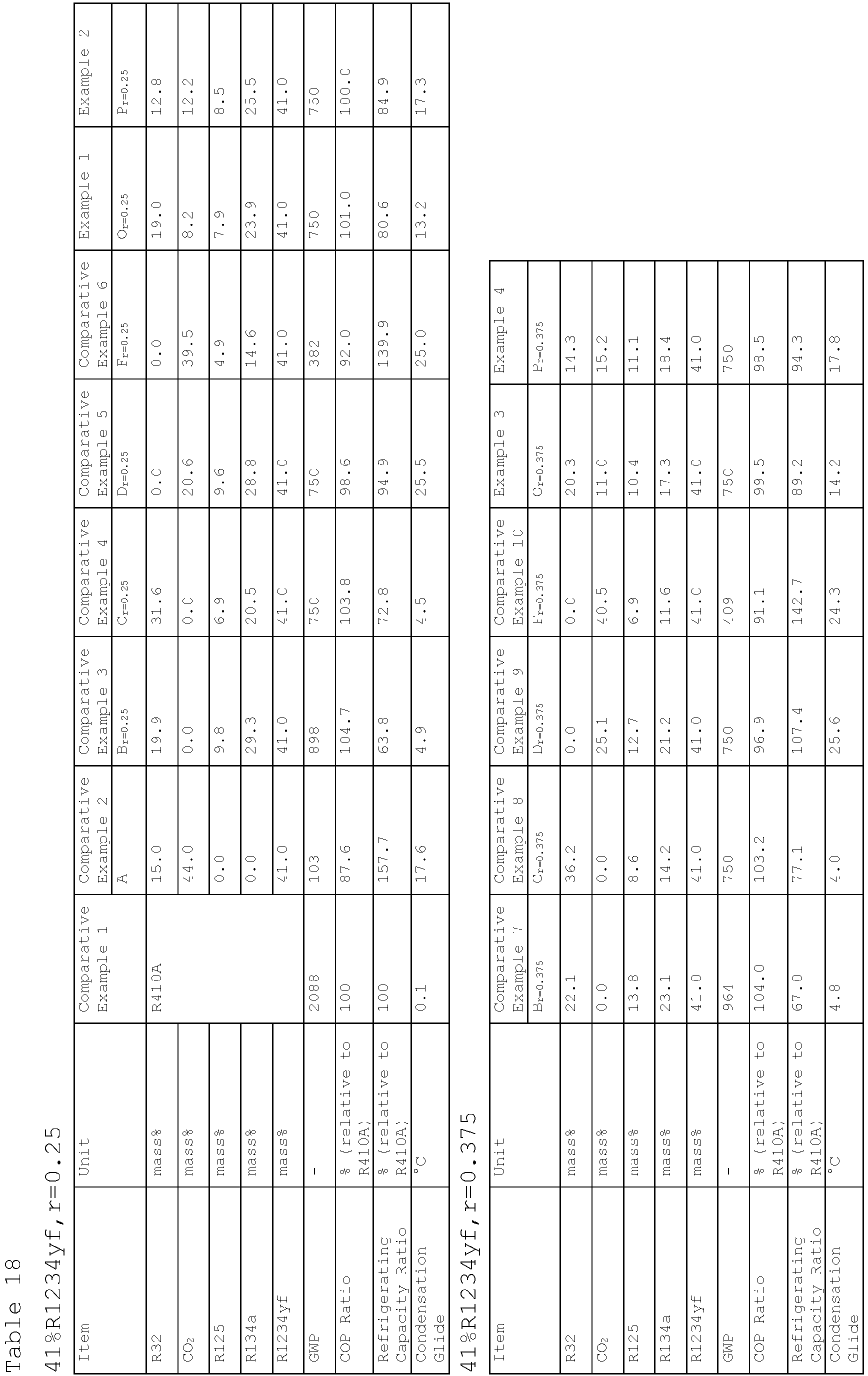


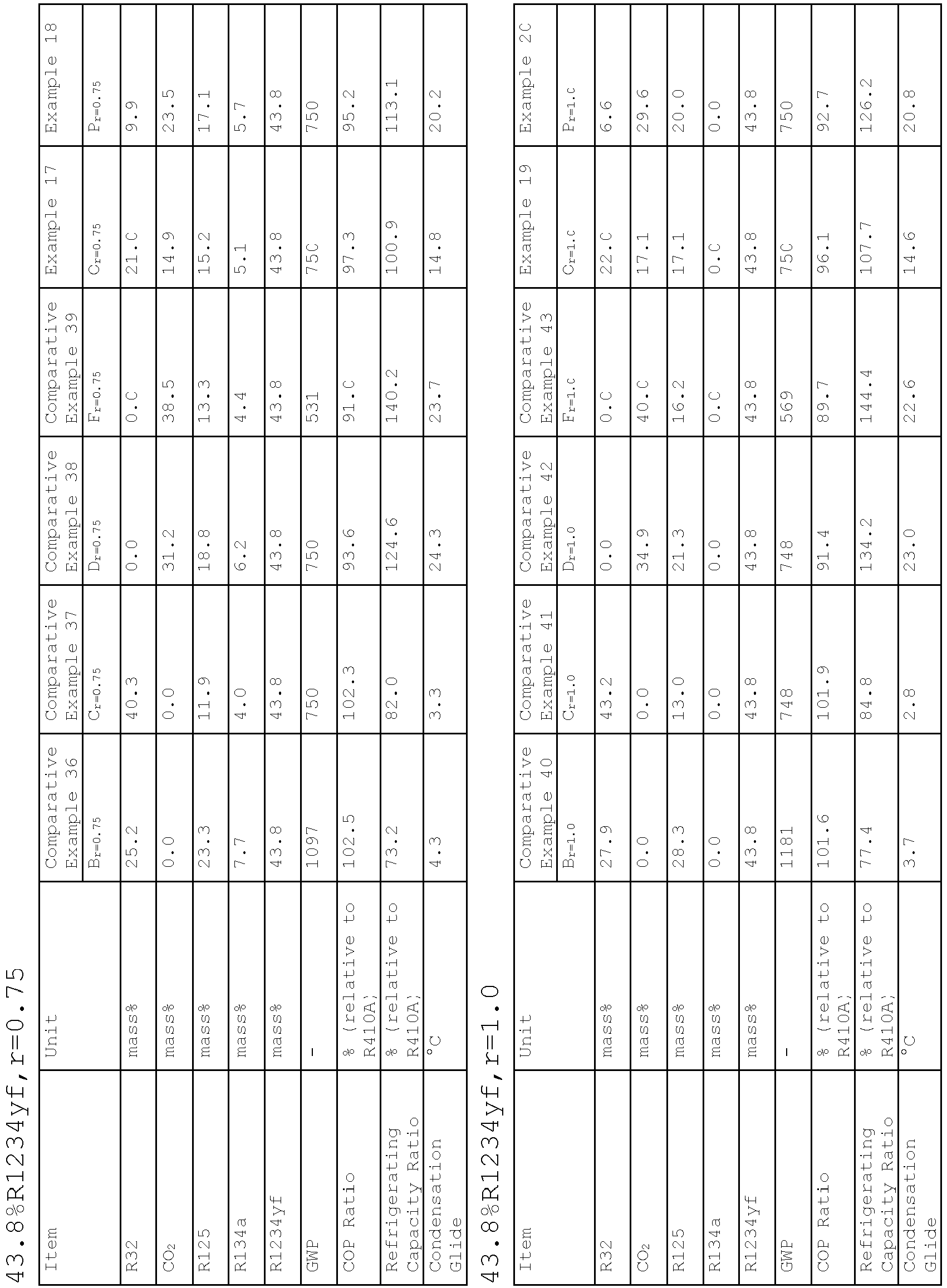


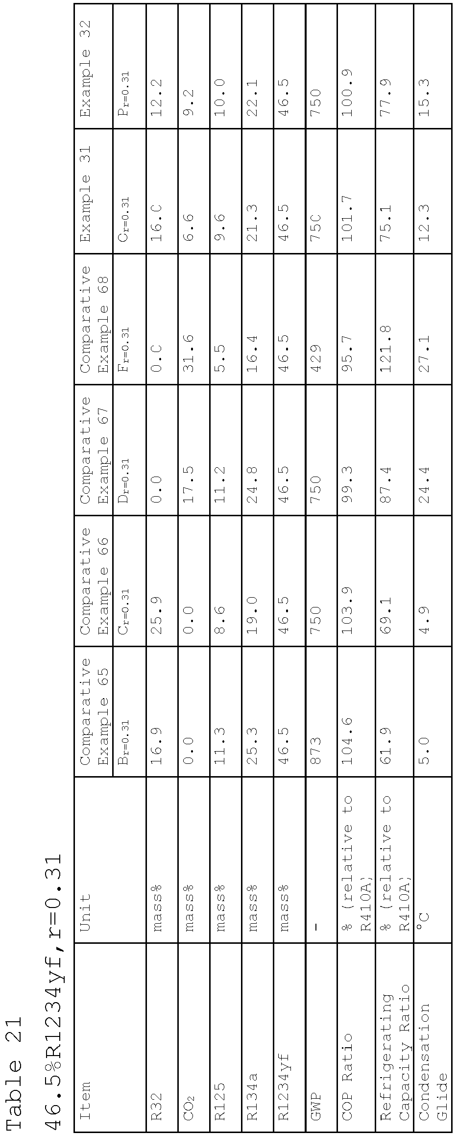


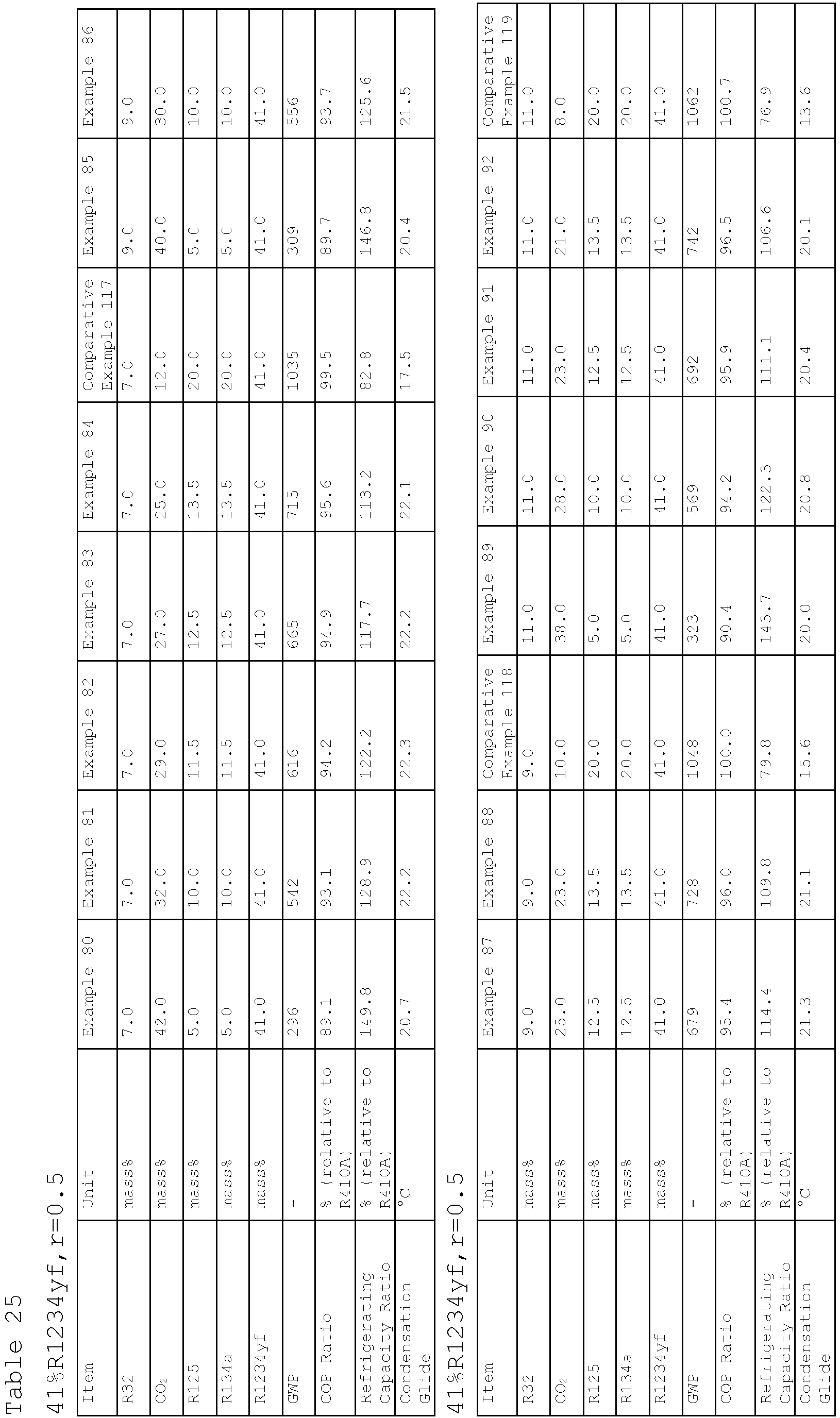


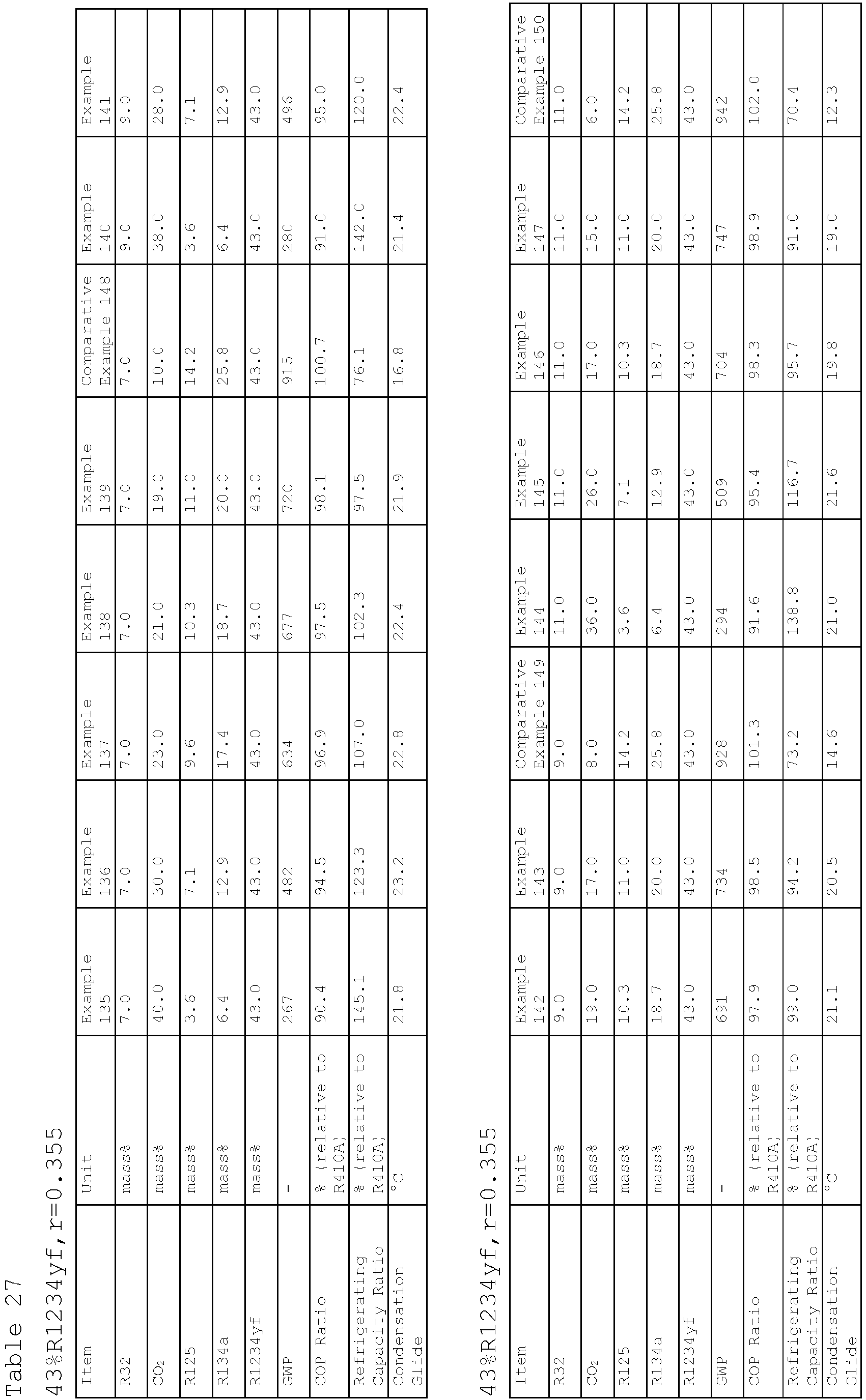


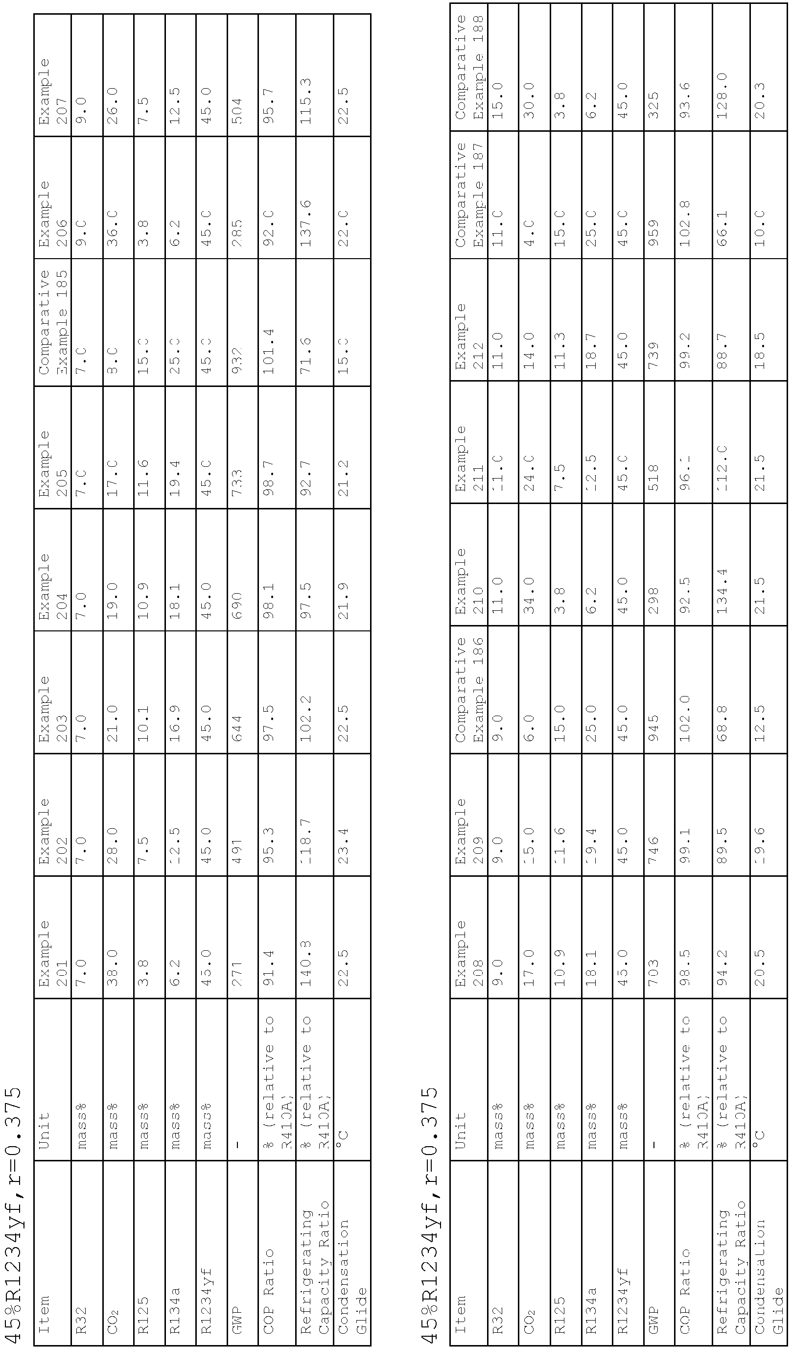


- The approximate expression of the coordinates of point A as a function of the proportion (x) of R1234yf was determined based on the four formulations of point A revealed above by using the least-squares method as described below. Specifically, the coordinates of point A were found to be (a,b,c) =(-0.6902x+43.307, 100-a-x, 0.0).
Table 31 a=R32 15.0 13.1 11.2 8.8 b=CO2 44.0 43.1 42.3 41.2 c=R125+R134a 0.0 0.0 0.0 0.0 x=R1234yf 41.0 43.8 46.5 50.0 x=R1234yf -0.6902x+43.307 a=R32 Approximate Expression b=CO2 Approximate Expression 100-a-x - Additionally, the approximate expression of the coordinates of point Br as r and a function of the proportion (x) of R1234yf was determined based on the formulations of point Br revealed above by using the least-squares method as described below.


- Additionally, the approximate expressions of the coordinates of point Cr and point Dr as r and a function of the proportion (x) of R1234yf were determined based on the formulations of point Cr and point Dr revealed above by using the least-squares method as described below.


- Each point Or, which is the intersection of line segment ABr and line segment CrDr, is shown in the Examples and Comparative Examples. The approximate expression of the coordinates of point Or as r and a function of the proportion (x) of R1234yf was determined based on the formulations of Or by using the least-squares method as described below.


- Each point Fr and each point Pr are shown in the Examples and Comparative Examples. The approximate expressions of the coordinates of point Fr and point Pr as r and a function of the proportion (x) of R1234yf were determined based on each formulation by using the least-squares method as described below.

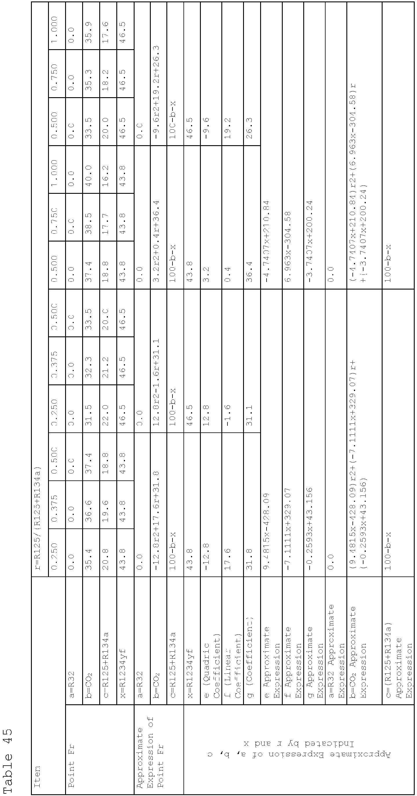


-
- 1:
- ignition source
- 2:
- sample inlet
- 3:
- springs
- 4:
- 12-liter glass flask
- 5:
- electrodes
- 6:
- stirrer
- 7:
- insulated chamber
- 10:
- refrigerating machine
- 11:
- refrigerant circuit
- 12:
- compressor
- 13:
- heat-source-side heat exchanger
- 14:
- expansion mechanism
- 15:
- user-side heat exchanger
- 16:
- fan
- 17:
- solenoid valve
- 18:
- four-way switching valve
- 19:
- heating means
- 20:
- bypass flow path
Claims (10)
- A composition comprising a refrigerant,the refrigerant comprising difluoromethane (R32), carbon dioxide (CO2), pentafluoroethane (R125), 1,1,1,2-tetrafluoroethane (R134a), and 2,3,3,3-tetrafluoropropene (R1234yf),
whereinwhen the mass% of R32 is a, the mass% of CO2 is b, the mass% of R125 is c1, the mass% of R134a is c2, the mass% of the sum of R125 and R134a is c, the mass% of R1234yf is x, and c1/(c1+c2) is r based on the sum of R32, CO2, R125, R134a, and R1234yf in the refrigerant,in a ternary composition diagram having R32 at a point of (100-x) mass%, CO2 at a point of (100-x) mass%, and the sum of R125 and R134a at a point of (100-x) mass% as vertices,1-1-1) when 43.8≥x≥41, and 0.5≥r≥0.25, coordinates (a,b,c) fall within a quadrangular region surrounded by line segments that connect the following points:point A (-0.6902x+43.307, 100-a-x, 0.0),point Or=0.25 to 0.5 ((-2.2857x+87.314)r2+(1.7143x-55.886)r+(-0.9643x+55.336), (2.2857x-112.91)r2+(-1.7143x+104.69)r+(-0.25x+11.05), 100-a-b-x),point Dr=0.25 to 0.5 (0.0, -28.8r2+54.0r+(-x+49.9), 100-b-x), andpoint Q (0.0, 100-x, 0.0),or on the line segments, excluding any point on line segment Dr=0.25 to 0.5 to Q, and line segment QA, or1-1-2) when 43.8≥x≥41, and 1.0≥r≥0.5, coordinates (a,b,c) fall within a quadrangular region surrounded by line segments that connect the following points:point A (-0.6902x+43.307, 100-a-x, 0.0),point Or=0.5 to 1.0 ((-0.2857x+8.5143)r2+(0.5x-10.9)r+(-0.8571x+52.543), (-0.2857x+4.5143)r2+(0.5x+0.9)r+(-0.7143x+33.586), 100-a-b-x),point Dr=0.5 to 1.0 (0.0, (-0.5714x+12.229)r2+(0.8571x-0.3429)r+(-1.2857x+66.814), 100-b-x), andpoint Q (0.0, 100-x, 0.0),or on the line segments, excluding any point on line segment Dr=0.5 to 1.0 to Q and line segment QA,or on the line segments, or1-2-1) when 46.5≥x≥43.8, and 0.5≥r≥0.25, coordinates (a,b,c) fall within a quadrangular region surrounded by line segments that connect the following points:point A (-0.6902x+43.307, 100-a-x, 0.0),point Or=0.25 to 0.5 ((1.1852x-64.711)r2+(-0.7407x+51.644)r+(-0.5556x+37.433), (-2.3704x+91.022)r2+(2.0741x-61.244)r+(-0.963x+42.278), 100-a-b-x),point Dr=0.25 to 0.5 (0.0, -28.8r2+54.0r+(-x+49.9), 100-b-x), andpoint Q (0.0, 100-x, 0.0),or on the line segments, excluding any point on line segment Dr=0.25 to 0.5 to Q and line segment QA, or1-2-2) when 46.5≥x≥43, and 1.0≥r≥0.5, coordinates (a,b,c) fall within a quadrangular region surrounded by line segments that connect the following points:point A (-0.6902x+43.307, 100-a-x, 0.0),point Or=0.5 to 1.0 ((0.2963x-16.978)r2+(-0.3704x+27.222)r+(-0.5185x+37.711), -8.0r2+22.8r+(-0.5185x+25.011), 100-a-b-x),point Dr=0.5 to 1.0 (0.0, -12.8r2+37.2r+(-x+54.3), 100-b-x), andpoint Q (0.0, 100-x, 0.0),or on the line segments, excluding any point on line segment Dr=0.5 to 1.0 to Q and line segment QA,1-3-1) when 50≥x≥46.5, and 0.5≥r≥0.25, coordinates (a,b,c) fall within a quadrangular region surrounded by line segments that connect the following points:point A (-0.6902x+43.307, 100-a-x, 0.0),point Or=0.25 to 0.5 (-9.6r2+17.2r+(-0.6571x+42.157), - 19.2r2+(0.2286x+24.571)r+(-0.6286x+26.729), 100-a-b-x),point Dr=0.25 to 0.5 (0.0, (0.9143x-71.314)r2+(-0.5714x+80.571)r+(-0.9143x+45.914), 100-b-x), andpoint Q (0.0, 100-x, 0.0),or on the line segments, excluding any point on line segment Dr=0.25 to 0.5 to Q and line segment QA, or1-3-2) when 50≥x≥46.5, and 1.0≥r≥0.5, coordinates (a,b,c) fall within a quadrangular region surrounded by line segments that connect the following points:point A (-0.6902x+43.307, 100-a-x, 0.0),point Or=0.5 to 1.0 ((-0.2286x+7.4286)r2+(0.4x-8.6)r+(-0.8x+50.8), (0.2286x-18.629)r2+(-0.2857x+36.086)r+(-0.4286x+20.829), 100-a-b-x),point Dr=0.5 to 1.0 (0.0, (0.2286x-23.429)r2+(-0.4x+55.8)r+(-0.8286x+46.329), 100-b-x), andpoint Q (0.0, 100-x, 0.0),or on the line segments, excluding any point on line segment Dr=0.5 to 1.0 to Q and line segment QA. - A composition comprising a refrigerant,the refrigerant comprising R32, CO2, R125, R134a, and R1234yf,
whereinwhen the mass% of R32 is a, the mass% of CO2 is b, the mass% of R125 is c1, the mass% of R134a is c2, the mass% of the sum of R125 and R134a is c, the mass% of R1234yf is x, and c1/(c1+c2) is r based on the sum of R32, CO2, R125, R134a, and R1234yf in the refrigerant,in a ternary composition diagram having R32 at a point of (100-x) mass%, CO2 at a point of (100-x) mass%, and the sum of R125 and R134a at a point of (100-x) mass% as vertices,2-1-1) when 43.8≥x≥41, and 0.5≥r≥0.25, coordinates (a,b,c) fall within a triangular region surrounded by line segments that connect the following points:point Fr=0.25 to 0.5 (0.0, (-1.1429x+37.257)r2+(1.2857x-38.714) r-(-1.7143x+106.89), 100-b-x),point Pr=0.25 to 0.5 ((-1.1429x+34.057)r2+(1.0x-21.0)r+(-0.4643x+27.636), (2.2857x-119.31)r2+(-2.0x+122.0)r+(-0.3929x+19.907), 100-a-b-x), andpoint Dr=0.25 to 0.5 (0.0, -28.8r2+54.0r+(-x+49.9), 100-b-x),or on the line segments, excluding any point on line segment Dr=0.25 to 0.5 to Fr=0.25 to 0.5, or2-1-2) when 43.8≥x≥41, and 1.0≥r≥0.5, coordinates (a,b,c) fall within a triangular region surrounded by line segments that connect the following points:point Fr=0.5 to 1.0 (0.0, (3.7143x-159.49)r2+(-5.0714x+222.53)r+(0.25x+25.45), 100-b-x),point Pr=0.5 to 1.0 ((3.4286x-138.17)r2+(-5.4286x+203.57)r+(1.6071x-41.593), (-2.8571x+106.74)r2+(4.5714x-143.63)r+(-2.3929x+96.027), 100-a-b-x), andpoint Dr=0.5 to 1.0 (0.0, (-0.5714x+12.229)r2+(0.8571x-0.3429)r+(-1.2857x+66.814), 100-b-x),or on the line segments, excluding any point on line segment Dr=0.5 to 1.0 to Fr=0.5 to 1.0, or2-2-1) when 46.5≥x≥43, and 0.5≥r≥0.25, coordinates (a,b,c) fall within a triangular region surrounded by line segments that connect the following points:point Fr=0.25 to 0.5 (0.0, (9.4815x-428.09)r2+(-7.1111x+329.07)r+(-0.2593x+43.156), 100-b-x),point Pr=0.25 to 0.5 ((-8.2963x+347.38)r2+(4.8889x-191.33)r+(-0.963x+49.478), (7.1111x-330.67)r2+(-4.1481x+216.09)r+(-0.2593x+14.056), 100-a-b-x), andpoint Dr=0.25 to 0.5 (0.0, -28.8r2+54.0r+(-x+49.9), 100-b-x),or on the line segments, excluding any point on line segment Dr=0.25 to 0.5 to Fr=0.25 to 0.5, or2-2-2) when 46.5≥x≥43, and 1.0≥r≥0.5, coordinates (a,b,c) fall within a triangular region surrounded by line segments that connect the following points:point Fr=0.5 to 1.0 (0.0, (-4.7407x+210.84)r2+(6.963x-304.58)r+(-3.7407x+200.24), 100-b-x),point Pr=0.5 to 1.0 ((0.2963x-0.9778)r2+(0.2222x-43.933)r+(-0.7778x+62.867), (-0.2963x-5.4222)r2+(-0.0741x+59.844)r+(-0.4444x+10.867), 100-a-b-x), andpoint Dr=0.5 to 1.0 (0.0, -12.8r2+37.2r+(-x+54.3), 100-b-x),or on the line segments, excluding any point on line segment Dr=0.5 to 1.0 to Fr=0.5 to 1.0, or2-3-1) when 50≥x≥46.5, and 0.37≥r≥0.25, coordinates (a,b,c) fall within a triangular region surrounded by line segments that connect the following points:point Fr=0.25 to 0.37 (0.0, (-35.714x+1744.0)r2+(23.333x-1128.3)r+(-5.144x+276.32), 100-b-x),point Pr=0.25 to 0.37 ((11.905x-595.24)r2+(-7.6189x+392.61)r+(0.9322x-39.027), (-27.778x+1305.6)r2+(17.46x-796.35)r+(-3.5147x+166.48), 100-a-b-x), andpoint Dr=0.25 to 0.37 (0.0, (0.9143x-71.314)r2+(-0.5714x+80.571)r+(-0.9143x+45.914), 100-b-x),or on the line segments, excluding any point on line segment Dr=0.25 to 0.37 to Fr=0.25 to 0.37, or2-3-2) when 50≥x≥46.5, and 1.0≥r≥0.5, coordinates (a,b,c) fall within a triangular region surrounded by line segments that connect the following points:point Fr=0.5 to 1.0 (0.0, (2.2857x-115.89)r2+(-3.0857x+162.69)r+(-0.3714x+43.571), 100-b-x),point Pr=0.5 to 1.0 ((-3.2x+161.6)r2+(4.4571x-240.86)r+(-2.0857x+123.69), (2.5143x-136.11)r2+(-3.3714x+213.17)r+(0.5429x-35.043), 100-a-b-x), andpoint Dr=0.5 to 1.0 (0.0, (0.2286x-23.429)r2+(-0.4x+55.8)r+(-0.8286x+46.329), 100-b-x),or on the line segments, excluding any point on line segment Dr=0.5 to 1.0 to Fr=0.5 to 1.0. - The composition according to claim 1 or 2, comprising R32, CO2, R125, R134a, and R1234yf in a total amount of 99.5 mass% or more based on the entire refrigerant.
- The composition according to any one of claims 1 to 3, comprising a refrigeration oil.
- The composition according to any one of claims 1 to 4, wherein the refrigerant is for use as an alternative refrigerant for R410A.
- A refrigerating machine comprising the composition of any one of claims 1 to 5.
- The refrigerating machine according to claim 6, comprising a heat exchanger in which a flow of the refrigerant and a flow of an external heat medium are in countercurrent flow.
- The refrigerating machine according to claim 6 or 7, comprising a heat-source-side heat exchanger and a user-side heat exchanger, wherein when the user-side heat exchanger functions as an evaporator, the evaporating temperature of the refrigerant is 0°C or below.
- A refrigerating machine comprisinga refrigerant comprising R32, CO2, R125, R134a, and R1234yf, anda heat exchanger in which a flow of the refrigerant and a flow of an external heat medium are in countercurrent flow.
- A refrigerating machine comprisinga refrigerant comprising R32, CO2, R125, R134a, and R1234yf,a heat-source-side heat exchanger, anda user-side heat exchanger,
wherein when the user-side heat exchanger functions as an evaporator, the evaporating temperature of the refrigerant is 0°C or below.
Applications Claiming Priority (2)
| Application Number | Priority Date | Filing Date | Title |
|---|---|---|---|
| JP2019084708 | 2019-04-25 | ||
| PCT/JP2020/017777 WO2020218544A1 (en) | 2019-04-25 | 2020-04-24 | Coolant containing fluorinated hydrocarbon and carbon dioxide, use of same, refrigerating machine comprising same and method for operating said refrigerating machine |
Publications (2)
| Publication Number | Publication Date |
|---|---|
| EP3960832A1 true EP3960832A1 (en) | 2022-03-02 |
| EP3960832A4 EP3960832A4 (en) | 2023-07-19 |
Family
ID=72942574
Family Applications (1)
| Application Number | Title | Priority Date | Filing Date |
|---|---|---|---|
| EP20794832.4A Withdrawn EP3960832A4 (en) | 2019-04-25 | 2020-04-24 | REFRIGERANT CONTAINING FLUORINATED HYDROCARBON AND CARBON DIOXIDE, USE THEREOF, REFRIGERATING MACHINE COMPRISING IT AND METHOD FOR OPERATING SAID REFRIGERATING MACHINE |
Country Status (5)
| Country | Link |
|---|---|
| US (1) | US20220073802A1 (en) |
| EP (1) | EP3960832A4 (en) |
| JP (2) | JP6908155B2 (en) |
| CN (1) | CN113840892B (en) |
| WO (1) | WO2020218544A1 (en) |
Families Citing this family (1)
| Publication number | Priority date | Publication date | Assignee | Title |
|---|---|---|---|---|
| CN112004908B (en) * | 2018-04-25 | 2022-02-18 | 大金工业株式会社 | Composition containing refrigerant, use thereof, method of freezing using the same, and refrigerator having the same |
Family Cites Families (9)
| Publication number | Priority date | Publication date | Assignee | Title |
|---|---|---|---|---|
| RU2547118C2 (en) * | 2010-05-20 | 2015-04-10 | Мексичем Аманко Холдинг С.А. Де С.В. | Heat-exchange compositions |
| JP2013533896A (en) * | 2010-05-20 | 2013-08-29 | メキシケム、アマンコ、ホールディング、ソシエダッド、アノニマ、デ、カピタル、バリアブレ | Heat transfer composition |
| ES2754267T3 (en) * | 2013-10-10 | 2020-04-16 | Chemours Co Fc Llc | Compositions comprising difluoromethane, pentafluoroethane, tetrafluoroethane and tetrafluoropropene and uses thereof |
| MY182105A (en) * | 2015-02-19 | 2021-01-18 | Daikin Ind Ltd | Composition containing mixture of fluorinated hydrocarbons, and method for producing same |
| CA3015523A1 (en) * | 2016-02-29 | 2017-09-08 | The Chemours Company Fc, Llc | Refrigerant mixtures comprising difluoromethane, pentafluoroethane, tetrafluoroethane, tetrafluoropropene, and carbon dioxide and uses thereof |
| JP6841066B2 (en) * | 2017-02-03 | 2021-03-10 | ダイキン工業株式会社 | A method of using a mixture of fluorinated hydrocarbons as a refrigerant, and a refrigerating device using the mixture as a refrigerant. |
| CN108865341B (en) * | 2017-05-09 | 2021-12-24 | 日本太阳石油株式会社 | Refrigerating machine oil composition and working fluid for refrigerator |
| JP6586984B2 (en) * | 2017-12-12 | 2019-10-09 | ダイキン工業株式会社 | Refrigerant containing fluorinated hydrocarbon and carbon dioxide, use thereof, refrigerator having the same, and method of operating the refrigerator |
| CN112004908B (en) * | 2018-04-25 | 2022-02-18 | 大金工业株式会社 | Composition containing refrigerant, use thereof, method of freezing using the same, and refrigerator having the same |
-
2020
- 2020-04-24 JP JP2020077245A patent/JP6908155B2/en active Active
- 2020-04-24 EP EP20794832.4A patent/EP3960832A4/en not_active Withdrawn
- 2020-04-24 CN CN202080031049.7A patent/CN113840892B/en active Active
- 2020-04-24 WO PCT/JP2020/017777 patent/WO2020218544A1/en not_active Ceased
-
2021
- 2021-05-10 JP JP2021079974A patent/JP2021120464A/en active Pending
- 2021-10-22 US US17/508,074 patent/US20220073802A1/en not_active Abandoned
Also Published As
| Publication number | Publication date |
|---|---|
| WO2020218544A1 (en) | 2020-10-29 |
| JP6908155B2 (en) | 2021-07-21 |
| US20220073802A1 (en) | 2022-03-10 |
| CN113840892A (en) | 2021-12-24 |
| JP2021120464A (en) | 2021-08-19 |
| EP3960832A4 (en) | 2023-07-19 |
| CN113840892B (en) | 2024-04-16 |
| JP2020180288A (en) | 2020-11-05 |
Similar Documents
| Publication | Publication Date | Title |
|---|---|---|
| EP3730570B1 (en) | Refrigerant cycling device | |
| EP3786252B1 (en) | Composition containing coolant, heat transfer medium and heat cycle system | |
| US11034871B2 (en) | Composition containing refrigerant and application of said composition | |
| WO2019124360A1 (en) | Air conditioner | |
| EP3725861A1 (en) | Refrigerant containing carbon dioxide and fluorinated hydrocarbon, use therefor, refrigerating machine provided with same, and operation method for said refrigerating machine | |
| EP3640313B1 (en) | Composition containing refrigerant, use of same, freezing method using same, and freezing machine including same | |
| US10988652B2 (en) | Method for using a mixture of fluorinated hydrocarbons as a refrigerant, and a refrigeration unit using the mixture as a refrigerant | |
| EP3786253A1 (en) | Refrigerant-containing composition, use thereof, refrigerating method using same, and refrigerator comprising same | |
| US11952529B2 (en) | Composition containing refrigerant comprising R32, R125, R143A, R1234YF and R134A, and refrigeration method, refrigerator operating method and refrigerator using said composition | |
| US20220073802A1 (en) | Coolant containing fluorinated hydrocarbon and carbon dioxide, use of same, refrigerating machine comprising same and method for operating said refrigerating machine | |
| JP7549270B2 (en) | COMPOSITIONS CONTAINING REFRIGERANTS, USES THEREOF, AND REFRIGERATORS HAVING SAME AND METHOD FOR OPERATION OF SAME - Patent application |
Legal Events
| Date | Code | Title | Description |
|---|---|---|---|
| STAA | Information on the status of an ep patent application or granted ep patent |
Free format text: STATUS: THE INTERNATIONAL PUBLICATION HAS BEEN MADE |
|
| PUAI | Public reference made under article 153(3) epc to a published international application that has entered the european phase |
Free format text: ORIGINAL CODE: 0009012 |
|
| STAA | Information on the status of an ep patent application or granted ep patent |
Free format text: STATUS: REQUEST FOR EXAMINATION WAS MADE |
|
| 17P | Request for examination filed |
Effective date: 20211125 |
|
| AK | Designated contracting states |
Kind code of ref document: A1 Designated state(s): AL AT BE BG CH CY CZ DE DK EE ES FI FR GB GR HR HU IE IS IT LI LT LU LV MC MK MT NL NO PL PT RO RS SE SI SK SM TR |
|
| DAV | Request for validation of the european patent (deleted) | ||
| DAX | Request for extension of the european patent (deleted) | ||
| RAP3 | Party data changed (applicant data changed or rights of an application transferred) |
Owner name: DAIKIN INDUSTRIES, LTD. |
|
| P01 | Opt-out of the competence of the unified patent court (upc) registered |
Effective date: 20230525 |
|
| A4 | Supplementary search report drawn up and despatched |
Effective date: 20230619 |
|
| RIC1 | Information provided on ipc code assigned before grant |
Ipc: F25B 13/00 20060101ALI20230613BHEP Ipc: F25B 9/00 20060101ALI20230613BHEP Ipc: F25B 5/02 20060101ALI20230613BHEP Ipc: C09K 5/04 20060101AFI20230613BHEP |
|
| STAA | Information on the status of an ep patent application or granted ep patent |
Free format text: STATUS: THE APPLICATION HAS BEEN WITHDRAWN |
|
| 18W | Application withdrawn |
Effective date: 20250807 |