EP3960569B1 - Vehicle control device and computer program - Google Patents
Vehicle control device and computer program Download PDFInfo
- Publication number
- EP3960569B1 EP3960569B1 EP20796088.1A EP20796088A EP3960569B1 EP 3960569 B1 EP3960569 B1 EP 3960569B1 EP 20796088 A EP20796088 A EP 20796088A EP 3960569 B1 EP3960569 B1 EP 3960569B1
- Authority
- EP
- European Patent Office
- Prior art keywords
- state
- state machine
- layer
- intermediate layer
- transition
- Prior art date
- Legal status (The legal status is an assumption and is not a legal conclusion. Google has not performed a legal analysis and makes no representation as to the accuracy of the status listed.)
- Active
Links
Images


Classifications
-
- B—PERFORMING OPERATIONS; TRANSPORTING
- B60—VEHICLES IN GENERAL
- B60W—CONJOINT CONTROL OF VEHICLE SUB-UNITS OF DIFFERENT TYPE OR DIFFERENT FUNCTION; CONTROL SYSTEMS SPECIALLY ADAPTED FOR HYBRID VEHICLES; ROAD VEHICLE DRIVE CONTROL SYSTEMS FOR PURPOSES NOT RELATED TO THE CONTROL OF A PARTICULAR SUB-UNIT
- B60W50/00—Details of control systems for road vehicle drive control not related to the control of a particular sub-unit, e.g. process diagnostic or vehicle driver interfaces
- B60W50/02—Ensuring safety in case of control system failures, e.g. by diagnosing, circumventing or fixing failures
- B60W50/035—Bringing the control units into a predefined state, e.g. giving priority to particular actuators
-
- B—PERFORMING OPERATIONS; TRANSPORTING
- B60—VEHICLES IN GENERAL
- B60W—CONJOINT CONTROL OF VEHICLE SUB-UNITS OF DIFFERENT TYPE OR DIFFERENT FUNCTION; CONTROL SYSTEMS SPECIALLY ADAPTED FOR HYBRID VEHICLES; ROAD VEHICLE DRIVE CONTROL SYSTEMS FOR PURPOSES NOT RELATED TO THE CONTROL OF A PARTICULAR SUB-UNIT
- B60W60/00—Drive control systems specially adapted for autonomous road vehicles
- B60W60/001—Planning or execution of driving tasks
- B60W60/0015—Planning or execution of driving tasks specially adapted for safety
- B60W60/0018—Planning or execution of driving tasks specially adapted for safety by employing degraded modes, e.g. reducing speed, in response to suboptimal conditions
- B60W60/00186—Planning or execution of driving tasks specially adapted for safety by employing degraded modes, e.g. reducing speed, in response to suboptimal conditions related to the vehicle
-
- B—PERFORMING OPERATIONS; TRANSPORTING
- B60—VEHICLES IN GENERAL
- B60W—CONJOINT CONTROL OF VEHICLE SUB-UNITS OF DIFFERENT TYPE OR DIFFERENT FUNCTION; CONTROL SYSTEMS SPECIALLY ADAPTED FOR HYBRID VEHICLES; ROAD VEHICLE DRIVE CONTROL SYSTEMS FOR PURPOSES NOT RELATED TO THE CONTROL OF A PARTICULAR SUB-UNIT
- B60W40/00—Estimation or calculation of non-directly measurable driving parameters for road vehicle drive control systems not related to the control of a particular sub unit, e.g. by using mathematical models
- B60W40/10—Estimation or calculation of non-directly measurable driving parameters for road vehicle drive control systems not related to the control of a particular sub unit, e.g. by using mathematical models related to vehicle motion
- B60W40/105—Speed
-
- B—PERFORMING OPERATIONS; TRANSPORTING
- B60—VEHICLES IN GENERAL
- B60W—CONJOINT CONTROL OF VEHICLE SUB-UNITS OF DIFFERENT TYPE OR DIFFERENT FUNCTION; CONTROL SYSTEMS SPECIALLY ADAPTED FOR HYBRID VEHICLES; ROAD VEHICLE DRIVE CONTROL SYSTEMS FOR PURPOSES NOT RELATED TO THE CONTROL OF A PARTICULAR SUB-UNIT
- B60W50/00—Details of control systems for road vehicle drive control not related to the control of a particular sub-unit, e.g. process diagnostic or vehicle driver interfaces
- B60W50/02—Ensuring safety in case of control system failures, e.g. by diagnosing, circumventing or fixing failures
- B60W50/0205—Diagnosing or detecting failures; Failure detection models
-
- B—PERFORMING OPERATIONS; TRANSPORTING
- B60—VEHICLES IN GENERAL
- B60W—CONJOINT CONTROL OF VEHICLE SUB-UNITS OF DIFFERENT TYPE OR DIFFERENT FUNCTION; CONTROL SYSTEMS SPECIALLY ADAPTED FOR HYBRID VEHICLES; ROAD VEHICLE DRIVE CONTROL SYSTEMS FOR PURPOSES NOT RELATED TO THE CONTROL OF A PARTICULAR SUB-UNIT
- B60W50/00—Details of control systems for road vehicle drive control not related to the control of a particular sub-unit, e.g. process diagnostic or vehicle driver interfaces
- B60W50/08—Interaction between the driver and the control system
- B60W50/14—Means for informing the driver, warning the driver or prompting a driver intervention
-
- B—PERFORMING OPERATIONS; TRANSPORTING
- B60—VEHICLES IN GENERAL
- B60W—CONJOINT CONTROL OF VEHICLE SUB-UNITS OF DIFFERENT TYPE OR DIFFERENT FUNCTION; CONTROL SYSTEMS SPECIALLY ADAPTED FOR HYBRID VEHICLES; ROAD VEHICLE DRIVE CONTROL SYSTEMS FOR PURPOSES NOT RELATED TO THE CONTROL OF A PARTICULAR SUB-UNIT
- B60W60/00—Drive control systems specially adapted for autonomous road vehicles
- B60W60/001—Planning or execution of driving tasks
-
- B—PERFORMING OPERATIONS; TRANSPORTING
- B60—VEHICLES IN GENERAL
- B60W—CONJOINT CONTROL OF VEHICLE SUB-UNITS OF DIFFERENT TYPE OR DIFFERENT FUNCTION; CONTROL SYSTEMS SPECIALLY ADAPTED FOR HYBRID VEHICLES; ROAD VEHICLE DRIVE CONTROL SYSTEMS FOR PURPOSES NOT RELATED TO THE CONTROL OF A PARTICULAR SUB-UNIT
- B60W60/00—Drive control systems specially adapted for autonomous road vehicles
- B60W60/005—Handover processes
- B60W60/0053—Handover processes from vehicle to occupant
-
- B—PERFORMING OPERATIONS; TRANSPORTING
- B60—VEHICLES IN GENERAL
- B60W—CONJOINT CONTROL OF VEHICLE SUB-UNITS OF DIFFERENT TYPE OR DIFFERENT FUNCTION; CONTROL SYSTEMS SPECIALLY ADAPTED FOR HYBRID VEHICLES; ROAD VEHICLE DRIVE CONTROL SYSTEMS FOR PURPOSES NOT RELATED TO THE CONTROL OF A PARTICULAR SUB-UNIT
- B60W60/00—Drive control systems specially adapted for autonomous road vehicles
- B60W60/005—Handover processes
- B60W60/0059—Estimation of the risk associated with autonomous or manual driving, e.g. situation too complex, sensor failure or driver incapacity
-
- G—PHYSICS
- G06—COMPUTING OR CALCULATING; COUNTING
- G06F—ELECTRIC DIGITAL DATA PROCESSING
- G06F11/00—Error detection; Error correction; Monitoring
- G06F11/30—Monitoring
- G06F11/3003—Monitoring arrangements specially adapted to the computing system or computing system component being monitored
- G06F11/3013—Monitoring arrangements specially adapted to the computing system or computing system component being monitored where the computing system is an embedded system, i.e. a combination of hardware and software dedicated to perform a certain function in mobile devices, printers, automotive or aircraft systems
-
- G—PHYSICS
- G06—COMPUTING OR CALCULATING; COUNTING
- G06F—ELECTRIC DIGITAL DATA PROCESSING
- G06F11/00—Error detection; Error correction; Monitoring
- G06F11/30—Monitoring
- G06F11/3089—Monitoring arrangements determined by the means or processing involved in sensing the monitored data, e.g. interfaces, connectors, sensors, probes, agents
-
- G—PHYSICS
- G06—COMPUTING OR CALCULATING; COUNTING
- G06F—ELECTRIC DIGITAL DATA PROCESSING
- G06F9/00—Arrangements for program control, e.g. control units
- G06F9/06—Arrangements for program control, e.g. control units using stored programs, i.e. using an internal store of processing equipment to receive or retain programs
- G06F9/44—Arrangements for executing specific programs
- G06F9/448—Execution paradigms, e.g. implementations of programming paradigms
- G06F9/4498—Finite state machines
-
- B—PERFORMING OPERATIONS; TRANSPORTING
- B60—VEHICLES IN GENERAL
- B60W—CONJOINT CONTROL OF VEHICLE SUB-UNITS OF DIFFERENT TYPE OR DIFFERENT FUNCTION; CONTROL SYSTEMS SPECIALLY ADAPTED FOR HYBRID VEHICLES; ROAD VEHICLE DRIVE CONTROL SYSTEMS FOR PURPOSES NOT RELATED TO THE CONTROL OF A PARTICULAR SUB-UNIT
- B60W50/00—Details of control systems for road vehicle drive control not related to the control of a particular sub-unit, e.g. process diagnostic or vehicle driver interfaces
- B60W2050/0001—Details of the control system
- B60W2050/0002—Automatic control, details of type of controller or control system architecture
- B60W2050/0004—In digital systems, e.g. discrete-time systems involving sampling
- B60W2050/0005—Processor details or data handling, e.g. memory registers or chip architecture
-
- B—PERFORMING OPERATIONS; TRANSPORTING
- B60—VEHICLES IN GENERAL
- B60W—CONJOINT CONTROL OF VEHICLE SUB-UNITS OF DIFFERENT TYPE OR DIFFERENT FUNCTION; CONTROL SYSTEMS SPECIALLY ADAPTED FOR HYBRID VEHICLES; ROAD VEHICLE DRIVE CONTROL SYSTEMS FOR PURPOSES NOT RELATED TO THE CONTROL OF A PARTICULAR SUB-UNIT
- B60W50/00—Details of control systems for road vehicle drive control not related to the control of a particular sub-unit, e.g. process diagnostic or vehicle driver interfaces
- B60W2050/0001—Details of the control system
- B60W2050/0002—Automatic control, details of type of controller or control system architecture
- B60W2050/0016—State machine analysis
-
- B—PERFORMING OPERATIONS; TRANSPORTING
- B60—VEHICLES IN GENERAL
- B60W—CONJOINT CONTROL OF VEHICLE SUB-UNITS OF DIFFERENT TYPE OR DIFFERENT FUNCTION; CONTROL SYSTEMS SPECIALLY ADAPTED FOR HYBRID VEHICLES; ROAD VEHICLE DRIVE CONTROL SYSTEMS FOR PURPOSES NOT RELATED TO THE CONTROL OF A PARTICULAR SUB-UNIT
- B60W50/00—Details of control systems for road vehicle drive control not related to the control of a particular sub-unit, e.g. process diagnostic or vehicle driver interfaces
- B60W50/02—Ensuring safety in case of control system failures, e.g. by diagnosing, circumventing or fixing failures
- B60W50/0205—Diagnosing or detecting failures; Failure detection models
- B60W2050/0215—Sensor drifts or sensor failures
-
- B—PERFORMING OPERATIONS; TRANSPORTING
- B60—VEHICLES IN GENERAL
- B60W—CONJOINT CONTROL OF VEHICLE SUB-UNITS OF DIFFERENT TYPE OR DIFFERENT FUNCTION; CONTROL SYSTEMS SPECIALLY ADAPTED FOR HYBRID VEHICLES; ROAD VEHICLE DRIVE CONTROL SYSTEMS FOR PURPOSES NOT RELATED TO THE CONTROL OF A PARTICULAR SUB-UNIT
- B60W50/00—Details of control systems for road vehicle drive control not related to the control of a particular sub-unit, e.g. process diagnostic or vehicle driver interfaces
- B60W50/08—Interaction between the driver and the control system
- B60W50/14—Means for informing the driver, warning the driver or prompting a driver intervention
- B60W2050/143—Alarm means
-
- B—PERFORMING OPERATIONS; TRANSPORTING
- B60—VEHICLES IN GENERAL
- B60W—CONJOINT CONTROL OF VEHICLE SUB-UNITS OF DIFFERENT TYPE OR DIFFERENT FUNCTION; CONTROL SYSTEMS SPECIALLY ADAPTED FOR HYBRID VEHICLES; ROAD VEHICLE DRIVE CONTROL SYSTEMS FOR PURPOSES NOT RELATED TO THE CONTROL OF A PARTICULAR SUB-UNIT
- B60W2420/00—Indexing codes relating to the type of sensors based on the principle of their operation
- B60W2420/40—Photo, light or radio wave sensitive means, e.g. infrared sensors
- B60W2420/403—Image sensing, e.g. optical camera
-
- G—PHYSICS
- G06—COMPUTING OR CALCULATING; COUNTING
- G06F—ELECTRIC DIGITAL DATA PROCESSING
- G06F11/00—Error detection; Error correction; Monitoring
- G06F11/30—Monitoring
- G06F11/3055—Monitoring arrangements for monitoring the status of the computing system or of the computing system component, e.g. monitoring if the computing system is on, off, available, not available
Definitions
- the present invention relates to a vehicle control device and a computer program.
- the complexity of an automatic driving system increases with the improvement of an automatic driving level and the expansion of an adaptation area.
- the automatic driving system needs not only to stop coping with a failure on the spot, and but also to continue automatic traveling even after a failure such as safe handover to a driver or deceleration to a safe speed.
- a large number of recognition devices represented by sensors are connected to a vehicle control device represented by an automatic driving electronic control unit (ECU) that realizes such an automatic driving system, and a large number of applications operate under various operation conditions in the vehicle control device. Accordingly, the design of state transition in the vehicle control device tends to be complicated.
- PTL 1 discloses a programming method for system state transition in a control system in which a system state is defined by a combination of a plurality of state machines.
- the programming method includes inputting a layer structure representing a configuration of the state machine, inputting an operation specification of each state machine, mapping the input operation specification of each state machine to a combination of the operation specification of the state machines corresponding to child nodes on the layer structure, storing information on the input mapping, and executing the state transition of each layer based on the stored information on the mapping when an event occurs.
- Prior art document US 2012/010772 A1 defines multi-level hierarchical state machines for vehicle control which process input data received from sensors. This data is condensed in intermediate layers whose output is fed to upper layers which control the actuators of the vehicle. T
- the automatic driving system since the automatic driving system has a large number of recognition devices, the number of lower-layer state machines to which events from recognition devices are input also increases. Thus, a relationship between which state machine of the intermediate layer receives an output from the lower-layer state machine becomes complicated, the complexity of the design of the state transition tends to increase.
- the present invention has been made in view of the above problems, and an object of the present invention is to provide a vehicle control device and a computer program capable of simplifying design of the state transition.
- a vehicle control device that controls a vehicle system, and includes a control unit that has a first state machine and a second state machine that are hierarchized, and an intermediate layer provided between the first state machine and the second state machine and a storage unit that stores a plurality of state transition tables provided for the first state machine and the second state machine, current states of the first state machine and the second state machine, states to transition, conditions of state transition being described in the state transition tables.
- the first state machine receives an event input from the vehicle system, refers to the state transition table, and outputs the state of the first state machine to the intermediate layer, the intermediate layer divides the state of the first state machine for each function of the vehicle system in association with the state of the first state machine, and outputs the state to the second state machine, the state transition table corresponding to the second state machine includes, as the condition of the state transition of the second state machine, the current state of the first state machine or the state to transition, and the second state machine receives the state of the first state machine input from the intermediate layer, refers to the state transition table, and outputs a signal for controlling the vehicle system.
- processing may be described with a "program" as an operation subject.
- processing is appropriately performed while using an appropriate storage resource (for example, memory) and/or an interface device (for example, keyboard) by a processor (for example, central processing unit (CPU)) executing a program
- a processor for example, central processing unit (CPU)
- CPU central processing unit
- all processing to be described below may be the processor.
- the processing described with the program as the operation subject may be processing performed by a device including the processor.
- a dedicated hardware circuit that performs a part or all of the processing performed by the processor may be included.
- a computer program may be installed on a device from a program source.
- the program source may be, for example, a program distribution server or a non-transitory computer-readable storage medium.
- a vehicle control device is a vehicle control device that controls a vehicle system.
- the vehicle control device includes a control unit that has a lower-layer state machine which is a first state machine and an upper-layer state machine which is a second state machine that are hierarchized, and an intermediate layer provided between the first state machine and the second state machine.
- the vehicle control device divides the state of the first state machine for each function of the vehicle system in association with the state of the first state machine, and outputs the state to the second state machine.
- the intermediate layers are integrated according to conditioning for switching between operations of the vehicle system, and are provided for recognition directions of recognition devices such as sensors of the vehicle system or target objects targeted by the recognition devices. More specifically, the intermediate layer is provided according to a determination criterion of behavior control of automatic driving in the upper-layer state machine. Accordingly, the second state machine can smoothly and reliably switch between the operations of the vehicle system by referring to the state transition of the intermediate layer.
- FIG. 1 is an overall configuration diagram of a vehicle control device according to a first embodiment.
- a vehicle system 1000 is a system mounted on a vehicle such as an automobile, and includes various sensors 12, various actuators 13, and an ECU 1 which is an example of a vehicle control device.
- the various sensors 12 and the various actuators 13 can communicate with the ECU 1 via in-vehicle networks 16 and 17.
- the in-vehicle networks 16 and 17 may be any communication networks such as Ethernet (registered trademark) and CAN-FD (CAN with Flexible Data-Rate).
- the various sensors 12 which are recognition devices include one or more sensors for capturing information on a surrounding environment of the vehicle, such as a radar, a light detection and ranging (LiDAR), and a camera.
- the various sensors 12 output pieces of state information of the sensors to the ECU 1.
- the various actuators 13 include one or more actuators for operating an accelerator, a brake, and a steering wheel for operating traveling of the vehicle.
- the various actuators 13 control the traveling of the vehicle based on input control information from the ECU 1.
- the ECU 1 includes a CPU 14 and a memory 15.
- the CPU 14 executes each processing according to a program stored in the memory 15.
- the memory 15 is, for example, a random access memory (RAM) or a read only memory (ROM), and stores a program executed by the CPU 14 and necessary information.
- processing programs 111A, 111B, 111C, and 111D of state machines event tables 112A, 112B, 112C, and 112D, state transition tables 113A, 113B, 113C, and 113D, and states 114A, 114B, 114C, and 114D of state machines are stored as a lower-layer state machine (first state machine) 11A, intermediate-layer state machines 11B and 11C, and an upper-layer state machine (second state machine) 11D. Functions of the programs will be described later.
- the program may be described as the operation subject for the sake of convenience, but an actual execution subject is the CPU 14 that executes the program.
- lower-layer state machine 11A and two intermediate-layer state machines 11B and 11C are illustrated in FIG. 1 , the number of lower-layer state machines and the number of intermediate-layer state machines are not limited to the illustrated example.
- FIG. 2 is a diagram illustrating an example of a functional configuration of the upper-layer state machine 11D according to the first embodiment.
- the functional configuration is described in a Data Flow Diagram format.
- the processing program 111A of the lower-layer state machine 11A receives event inputs from the various sensors 12 (pieces of state information of the sensors), stocks events from the various sensors 12 in the event table 112A, refers to the state transition table 113A based on the event and the state 114A of the state machine, and updates the state 114A of the state machine. After the state 114A is updated, pieces of information on the event and a guard condition are output to the intermediate-layer state machine 11B.
- FIG. 3 is a diagram illustrating an example of a functional configuration of the intermediate-layer state machine 11B according to the first embodiment.
- the ECU 1 according to the present embodiment includes the plurality of intermediate-layer state machines 11B and 11C, since these intermediate-layer state machines have the same functional configuration, the functional configuration of the intermediate-layer state machine 11B will be described here.
- the processing program 111B of the intermediate-layer state machine 11B stocks the input event from the processing program 111A of the lower-layer state machine 11A in the event table 112B, refers to the state transition table 113B based on the event and the state 114B of the state machine, and updates the state 114B of the state machine. After the state is updated, the pieces of information on the event and the guard condition are output to the upper-layer state machine 11D.
- FIG. 4 is a diagram illustrating an example of a functional configuration of the upper-layer state machine 11D according to the first embodiment.
- the processing program 111D of the upper-layer state machine 11D stocks the input event from the processing program 111B or 111C of the intermediate-layer state machine 11B or 11C in the event table 112D, refers to the state transition table 113D based on the event and the state 114D of the state machine, and updates the state 114D of the state machine. After the state is updated, control information is output to the various actuators 13.
- FIG. 5 is a diagram illustrating an example of the event table according to the first embodiment.
- the event tables 112A to 112D illustrated in FIGS. 1 to 4 have the same data structure.
- the event tables 112A to 112D are tables for stocking the events output from the sensors 12, the lower-layer state machine 11A, and the intermediate-layer state machines 11B and 11C.
- the events may be reflected in the order of receipt, or a priority may be separately determined in advance and may be reflected in the order of the priority.
- FIGS. 6A and 6B are diagrams illustrating the state transition tables 113A of the lower layer according to the first embodiment.
- FIGS. 6A and 6B illustrate an example in which the ECU 1 has two lower-layer state machines. Since the state transition tables 113A illustrated in FIGS. 6A and 6B have substantially the same data structure, FIG. 6A will be described.
- a vertical axis of the state transition table 113A represents the events input from the various sensors 12 to the lower-layer state machine 11A
- a horizontal axis represents the state of the lower-layer state machine 11A
- each cell represents a state to transition when the event occurs.
- the lower-layer state machine 11A transitions to an abnormal state.
- a transition destination of the lower-layer state machine is decided according to the input events from the various sensors 12 and a current state of the lower-layer state machine 11A.
- FIGS. 7A and 7B are diagrams illustrating examples of the state transition tables 113B and 113C of the intermediate layers according to the first embodiment. Since the state transition tables 113B and 113C illustrated in FIGS. 7A and 7B have substantially the same data structure, FIG. 7A will be described.
- a vertical axis, a horizontal axis, and each cell of the state transition table 113B of the intermediate layer are the same as those of the state transition table 113A of the lower layer except for points to be described below.
- the cells in the state transition table 113B of the intermediate layer there is a cell including [], and the guard condition is described in [].
- the state may or may not transition to another state, or the transition destination may vary.
- a condition for deciding the transition destination is referred to as a guard condition.
- the transition destination of the intermediate-layer state machine 11B is decided by the input event from the lower-layer state machine 11A, the current state, and the guard condition.
- FIG. 8 is a diagram illustrating an example of the state transition table 113D of the upper layer according to the first embodiment.
- a vertical axis, a horizontal axis, and each cell of the state transition table 113D of the upper layer are the same as those of the state transition tables 113B and 113C of the intermediate layers.
- the state of the upper-layer state machine 11D is a normal state 604
- the transition destination varies depending on the number of sensors in the normal state in the intermediate-layer state machine 11B or 11C.
- the state of the upper-layer state machine 11D transitions to a driver takeover state in a case where the number of normal sensors is less than two, and transitions to a function restriction state in a case where the number of normal sensors is equal to or more than two.
- the transition destination of the upper-layer state machine 11D is decided by the input event from the intermediate-layer state machine 11B or 11C, the current state, and the guard condition.
- FIG. 9A is a diagram illustrating sensors belonging to the right-side intermediate layer according to the first embodiment
- FIG. 9B is a diagram illustrating an example of the intermediate layers according to the first embodiment.
- two intermediate layers (a right-side intermediate layer 500 and a left-side intermediate layer) are provided.
- a right-side intermediate layer 500 when the vehicle is divided into left and right sides with an axis extending along a traveling direction as a center, an event from a sensor located on the right side of the vehicle or having a detection direction of the sensor 12 on the right side of the vehicle is input to the right-side intermediate layer 500.
- the intermediate-layer state machine is divided based on installation locations of the recognition devices exemplifying the various sensors 12 or recognition directions of the recognition devices, and events from the recognition devices of which the installation locations or recognition directions (detection directions of the sensors 12) are on the right side of the vehicle are input to the right-side intermediate layer 500.
- the intermediate layer illustrated in FIG. 9B is merely an example, and a form in which the intermediate layer is provided may be changed and adapted according to a condition for causing the state of the upper-layer state machine 11D to transition.
- the intermediate layer may be provided for each detection direction of the sensor 12 and/or target object targeted by the sensor.
- the target object include a stationary body, a moving body, a signal, and the like.
- the intermediate layer is provided for each detection direction and/or target object, and thus, it is possible to detect which part of the vehicle has failed and which detection has become difficult.
- the intermediate layer is provided for each condition for causing the state of the upper layer to transition, and thus, operations of the ECU 1 can be switched.
- FIG. 10 is a flowchart illustrating an example of the processing of the lower-layer state machine 11A according to the first embodiment.
- the state transition processing illustrated in the flowchart of FIG. 10 is executed by the CPU 14 executing the processing program 111A of the lower-layer state machine 11A.
- the state transition processing illustrated in FIG. 10 is executed, for example, when the state of the sensor 12 transitions.
- the processing of the processing program 111A of the state machine of the lower-layer state machine 11A will be described.
- the events are input from the various sensors 12, and thus, the events are stocked in the event table 112A (YES in S100).
- the processing program 111A of the lower-layer state machine 11A refers to the state transition table 113A based on the stocked event and the state 114A of the lower-layer state machine 11A (S110), and updates the state of the lower-layer state machine (S120).
- the processing program 111A of the state machine notifies the intermediate layer of the event (S140), and ends the processing.
- the processing program 111A of the state machine ends the processing at this time.
- FIG. 11 is a flowchart illustrating an example of the processing of the intermediate-layer state machine 11B or 11C according to the first embodiment.
- the state transition processing illustrated in the flowchart of FIG. 11 is executed by the CPU 14 executing the processing program 111B or 111C of the intermediate-layer state machine 11B or 11C.
- the state transition processing illustrated in FIG. 11 is executed when the state of the lower-layer state machine 11A transitions. Since the tasks of state transition processing executed by the processing programs 111B and 111C of the intermediate-layer state machines 11B and 11C are substantially the same, the processing of the processing program 111B of the intermediate-layer state machine 11B will be described below.
- the processing program 111B of the intermediate-layer state machine refers to the state transition table 113B based on the stocked event and the state 114B of the intermediate-layer state machine (S210).
- the processing program 111B of the intermediate-layer state machine refers to the state of the lower layer (S230) and updates the state (S240).
- the processing program 111B of the intermediate-layer state machine directly updates the state (S240).
- the processing program 111B of the intermediate-layer state machine notifies the upper layer of the event (S260).
- the processing program 111B of the intermediate-layer state machine ends the processing at this time.
- FIG. 12 is a flowchart illustrating an example of the processing of the upper-layer state machine 11D according to the first embodiment.
- the state transition processing illustrated in the flowchart of FIG. 12 is executed by the CPU 14 executing the processing program 111D of the upper-layer state machine 11D.
- the state transition processing illustrated in FIG. 12 is executed when the states of the intermediate-layer state machines 11B and 11C transition.
- the processing program 111D of the upper-layer state machine refers to the state transition table 113D based on the stocked event and the state 114D of the upper-layer state machine (S310).
- the processing program 111D of the upper-layer state machine refers to the state of the intermediate layer (S330), updates the state, and delivers control information to the various actuators 13 (S240).
- the processing program 111D of the upper-layer state machine directly updates the state, and delivers the control information to the various actuators 13 (S340). Thereafter, the processing program 111D of the upper-layer state machine ends the processing.
- the processing program 111D of the upper-layer state machine ends the processing at this time.
- FIGS. 13A to 13C are diagrams illustrating examples of state lists of the upper-layer state machine 11D, the intermediate-layer state machines 11B and 11C, and the lower-layer state machine 11A according to the first embodiment, respectively.
- a left column represents the number of state machines
- a right column represents a current state of each state machine.
- the state update for example, in a case where the state transitions to the abnormal state in lower layer 1, the state transitions from the normal state to the abnormal state by the state update.
- FIG. 14A is a diagram for describing an operation of a vehicle control device 1 according to the first embodiment.
- a host vehicle 400 travels straight on a two-lane road on each side, and a preceding vehicle 401 travels in front of the host vehicle 400. It is assumed that the host vehicle 400 intends to overtake the preceding vehicle 401.
- the state machine 11B or 11C of the right-side intermediate layer 520 refers to the state transition table 113B or 113C based on the event input from the lower-layer state machine 11A and the state 114B or 114C of the state machine.
- the intermediate-layer state machine 11B or 11C refers to the state of the lower-layer state machine 11A included in the target intermediate layer, and update the state 114B or 114C of the state machine of the intermediate layer to the abnormal state.
- the intermediate-layer state machine 11B or 11C stocks the event in the upper-layer state machine 11D.
- the upper-layer state machine 11D to which the event has been input transitions the state 114D of the upper-layer state machine to the function restriction state by causing the state 114B or 114C of the intermediate-layer state machine referring to the state transition table 113D to transition to the abnormal state.
- the upper-layer state machine 11D becomes the "driver takeover waiting" state on the assumption that the failures occur in all the sensors, and the upper-layer state machine 11D outputs the control signal for notifying a driver that the abnormality of the sensor or the like occurs.
- the state 114D of the upper-layer state machine merely transitions to the function restriction state, and control to immediately notify the driver of a warning is not performed.
- the intermediate-layer state machine 11B or 11C divides the state of the lower-layer state machine 11A for each function of the vehicle system 1000 in association with the state of the lower-layer state machine 11A and outputs the state to the upper-layer state machine 11D, and the upper-layer state machine 11D receives the state of the lower-layer state machine 11A input from the intermediate-layer state machine 11B or 11C, refers to the state transition table 113D, and outputs a signal for controlling the vehicle system 1000.
- the intermediate-layer state machine 11B or 11C divides the state of the lower-layer state machine for each direction of the sensor 12 in the vehicle system 1000 or each target object targeted by the sensor 12, and outputs the state of the lower-layer state machine 11A to the upper-layer state machine 11D.
- how to provide the intermediate layer is not limited to those described in the embodiment.
- the intermediate layer may be divided into the left and right sides as illustrated in the left part of FIG. 14B , but also the intermediate layer may be divided into front and rear sides as illustrated in the right part of FIG. 14B .
- the intermediate layer is divided into the front and rear sides
- events from sensors located on the front side of the vehicle or having the detection directions of the sensors 12 on the front side of the vehicle when the intermediate layer is divided into the front and rear sides in the traveling direction from the center of the vehicle are input to a front-side intermediate layer 501.
- All the intermediate layers illustrated in the left and right portions of FIG. 14B may be provided, in other words, the intermediate layer may be divided into four in the front-back direction and the left-right direction.
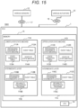
- FIG. 15 is an overall configuration diagram of a vehicle control device (ECU 1) according to a second embodiment.
- ECU 1 vehicle control device
- the ECU 1 which is the vehicle control device is different from the ECU 1 according to the first embodiment in the following points. That is, in intermediate layers 11B and 11C of a memory 15, processing programs 116B and 116C and reliability calculation programs 115B and 115C of the intermediate layers are stored instead of the processing programs 111B and 111C of the state machines, the state transition tables 113B and 113C, and the states 114B and 114C of the state machines.
- FIG. 16 is a diagram illustrating an example of a functional configuration of a lower-layer state machine 11A according to the second embodiment
- FIG. 17 is a diagram illustrating an example of a functional configuration of an intermediate layer 11B or 11C according to the second embodiment
- FIG. 18 is a diagram illustrating an example of a functional configuration of an upper-layer state machine 11D according to the second embodiment.
- the functional configurations illustrated in FIGS. 16 to 18 since the functional configurations illustrated in FIGS. 16 and 18 are the same as the functional configurations illustrated in FIGS. 2 and 4 of the first embodiment described above, the description thereof will be omitted here, and only the functional configuration of FIG. 17 will be described.
- the processing program 116B of the intermediate layer receives an event input (state notification information) from the lower-layer state machine 11A, stocks the event in an event table 112B or 112C, calculates degrees of reliability by the reliability calculation program 115B or 115C, and notifies the upper-layer state machine 11D of the event in a case where the degree of reliability is equal to or less than a threshold value. Details of the degree of reliability and a calculation method thereof will be described later.
- FIG. 19 is a flowchart illustrating an example of processing of the intermediate layer 11B or 11C according to the second embodiment.
- the state transition processing illustrated in the flowchart of FIG. 19 is executed when the state of the lower-layer state machine 11A transitions.
- the tasks of processing of the lower-layer state machine 11A and the upper-layer state machine 11D are the same as those of the first embodiment, the description thereof will be omitted. Since the tasks of state transition processing executed by the processing programs 116B and 116C of the intermediate layers are substantially the same, the processing of the processing program 116B of the state machine of the intermediate layer 11B will be described below.
- the processing program 116B of the intermediate layer calculates the degree of reliability of the sensor (S270). In a case where the degree of reliability calculated in S270 is equal to or less than a threshold value (YES in S280), and in a case where it is determined that reflection to the upper layer is required (YES in S250), the processing program 116B of the intermediate layer notifies the upper-layer state machine 11D of the event (S260).
- the processing program 116B of the intermediate layer ends the processing.
- the degree of reliability is a value indicating whether or not each of the various sensors 12 is performing a normal operation, and takes any one of a normal value and an abnormal value for each sensor.
- the degree of reliability is one when radio wave intensity received by the Radar is a normal value (in other words, measurement can be normally performed by the Radar), and the degree of reliability is zero when the radio wave intensity falls below the normal value by a predetermined value or more (including a case where the radio wave intensity is zero).
- the degree of reliability becomes one when contrast of a video signal of the camera indicates a normal value, and the degree of reliability becomes zero when the contrast falls below the normal value by a predetermined value or more.
- the processing program 116B or 116C of the intermediate layer calculates the degrees of reliability of the sensors 12 based on the event input from the lower-layer state machine 11A, and calculates the degrees of reliability in the intermediate layer by integrating the degrees of reliability. Accordingly, it can be said that the degree of reliability is a degree of redundancy indicating that the sensor 12 of which the event is input to the intermediate layer 11B or 11C via the lower-layer state machine 11A is normal.
- the threshold value is determined from the viewpoint of notifying the upper-layer state machine 11D of the event depending on how many sensors 12 have become abnormal.
- a processing program of a right-side intermediate layer 520 calculates the degrees of reliability of all the sensors 12 belonging to the right-side intermediate layer 520.
- the processing program 116B calculates the degrees of reliability of all the sensors 12 belonging to the right-side intermediate layer 520.
- an average degree of reliability in the right-side intermediate layer 520 is equal to or less than a threshold value
- the number of sensors equal to or less than the threshold value is one, but since the degree of reliability of the front right Radar 510 is zero, the event is stocked in the upper-layer state machine 11D.
- the upper-layer state machine 11D to which the event has been input refers to the state transition table 113D based on the input event and the state 114D of the state machine.
- the upper-layer state machine 11D transitions the state 114D of the upper-layer state machine to the function restriction state based on the degree of reliability of the intermediate layer 11B or 11C.
- the same effects as those of the first embodiment can also be obtained.
- the operations of the vehicle system 1001 can be switched only by calculating the degree of reliability of the target intermediate layer 11B or 11C.
- the present invention is not limited to the aforementioned embodiments, and includes various modification examples.
- control lines and information lines illustrated are considered to be necessary for the description, and not all the control lines and information lines in a product are necessarily illustrated. Almost all the configurations may be considered to be actually connected to each other.
Landscapes
- Engineering & Computer Science (AREA)
- Automation & Control Theory (AREA)
- Mechanical Engineering (AREA)
- Transportation (AREA)
- Human Computer Interaction (AREA)
- Theoretical Computer Science (AREA)
- Physics & Mathematics (AREA)
- General Physics & Mathematics (AREA)
- Software Systems (AREA)
- General Engineering & Computer Science (AREA)
- Mathematical Physics (AREA)
- Computing Systems (AREA)
- Quality & Reliability (AREA)
- Traffic Control Systems (AREA)
- Stored Programmes (AREA)
- Control Of Driving Devices And Active Controlling Of Vehicle (AREA)
Description
- The present invention relates to a vehicle control device and a computer program.
- The complexity of an automatic driving system increases with the improvement of an automatic driving level and the expansion of an adaptation area. The automatic driving system needs not only to stop coping with a failure on the spot, and but also to continue automatic traveling even after a failure such as safe handover to a driver or deceleration to a safe speed. A large number of recognition devices represented by sensors are connected to a vehicle control device represented by an automatic driving electronic control unit (ECU) that realizes such an automatic driving system, and a large number of applications operate under various operation conditions in the vehicle control device. Accordingly, the design of state transition in the vehicle control device tends to be complicated.
- As a technology for inserting an intermediate layer in order to simplify a complicated correspondence between state machines having different hierarchies, for example, there is a technology described in
PTL 1.PTL 1 discloses a programming method for system state transition in a control system in which a system state is defined by a combination of a plurality of state machines. The programming method includes inputting a layer structure representing a configuration of the state machine, inputting an operation specification of each state machine, mapping the input operation specification of each state machine to a combination of the operation specification of the state machines corresponding to child nodes on the layer structure, storing information on the input mapping, and executing the state transition of each layer based on the stored information on the mapping when an event occurs. - PTL 1:
JP H07-212861 A - Prior art document
US 2012/010772 A1 defines multi-level hierarchical state machines for vehicle control which process input data received from sensors. This data is condensed in intermediate layers whose output is fed to upper layers which control the actuators of the vehicle. T - However, the technology disclosed in
PTL 1 does not describe how to integrate the intermediate layer. In a case where state transition of a vehicle control device used in an advanced automatic driving system is designed, the complexity of the design of the state transition cannot be reduced unless an appropriate intermediate layer is provided. - In particular, since the automatic driving system has a large number of recognition devices, the number of lower-layer state machines to which events from recognition devices are input also increases. Thus, a relationship between which state machine of the intermediate layer receives an output from the lower-layer state machine becomes complicated, the complexity of the design of the state transition tends to increase.
- The present invention has been made in view of the above problems, and an object of the present invention is to provide a vehicle control device and a computer program capable of simplifying design of the state transition.
- In order to solve the above problems, a vehicle control device according to one aspect of the present invention that controls a vehicle system, and includes a control unit that has a first state machine and a second state machine that are hierarchized, and an intermediate layer provided between the first state machine and the second state machine and a storage unit that stores a plurality of state transition tables provided for the first state machine and the second state machine, current states of the first state machine and the second state machine, states to transition, conditions of state transition being described in the state transition tables. The first state machine receives an event input from the vehicle system, refers to the state transition table, and outputs the state of the first state machine to the intermediate layer, the intermediate layer divides the state of the first state machine for each function of the vehicle system in association with the state of the first state machine, and outputs the state to the second state machine, the state transition table corresponding to the second state machine includes, as the condition of the state transition of the second state machine, the current state of the first state machine or the state to transition, and the second state machine receives the state of the first state machine input from the intermediate layer, refers to the state transition table, and outputs a signal for controlling the vehicle system.
- The invention is specified by the independent claims. Further preferred embodiments are defined by the dependent claims.
- According to the present invention, it is possible to realize a vehicle control device and a computer program capable of simplifying the design of the state transition.
-
- [
FIG. 1] FIG. 1 is an overall configuration diagram of a vehicle control device according to a first embodiment. - [
FIG. 2] FIG. 2 is a diagram illustrating an example of a functional configuration of a lower-layer state machine according to the first embodiment. - [
FIG. 3] FIG. 3 is a diagram illustrating an example of a functional configuration of an intermediate-layer state machine according to the first embodiment. - [
FIG. 4] FIG. 4 is a diagram illustrating an example of a functional configuration of an upper-layer state machine according to the first embodiment. - [
FIG. 5] FIG. 5 is a diagram illustrating an example of an event table according to the first embodiment. - [
FIG. 6A] FIG. 6A is a diagram illustrating an example of a state transition table of a lower layer according to the first embodiment. - [
FIG. 6B] FIG. 6B is a diagram illustrating another example of the state transition table of the lower layer according to the first embodiment. - [
FIG. 7A] FIG. 7A is a diagram illustrating an example of a state transition table of an intermediate layer according to the first embodiment. - [
FIG. 7B] FIG. 7B is a diagram illustrating another example of the state transition table of the intermediate layer according to the first embodiment. - [
FIG. 8] FIG. 8 is a diagram illustrating an example of a state transition table of an upper layer according to the first embodiment. - [
FIG. 9A] FIG. 9A is a diagram illustrating a sensor belonging to a right-side intermediate layer according to the first embodiment. - [
FIG. 9B] FIG. 9B is a diagram illustrating an example of an intermediate layer according to the first embodiment. - [
FIG. 10] FIG. 10 is a flowchart illustrating an example of processing of the lower-layer state machine according to the first embodiment. - [
FIG. 11] FIG. 11 is a flowchart illustrating an example of processing of the intermediate-layer state machine according to the first embodiment. - [
FIG. 12] FIG. 12 is a flowchart illustrating an example of processing of the upper-layer state machine according to the first embodiment. - [
FIG. 13A] FIG. 13A is a diagram illustrating an example of a state list of the upper-layer state machine according to the first embodiment. - [
FIG. 13B] FIG. 13B is a diagram illustrating an example of a state list of the intermediate-layer state machine according to the first embodiment. - [
FIG. 13C] FIG. 13C is a diagram illustrating an example of a state list of the lower-layer state machine according to the first embodiment. - [
FIG. 14A] FIG. 14A is a diagram for describing an operation of the vehicle control device according to the first embodiment. - [
FIG. 14B] FIG. 14B is a diagram illustrating another example of the intermediate layer according to the first embodiment. - [
FIG. 15] FIG. 15 is an overall configuration diagram of a vehicle control device according to the second embodiment. - [
FIG. 16] FIG. 16 is a diagram illustrating an example of a functional configuration of a lower-layer state machine according to the second embodiment. - [
FIG. 17] FIG. 17 is a diagram illustrating an example of a functional configuration of an intermediate layer according to the second embodiment. - [
FIG. 18] FIG. 18 is a diagram illustrating an example of a functional configuration of an upper-layer state machine according to the second embodiment. - [
FIG. 19] FIG. 19 is a flowchart illustrating an example of processing of an intermediate layer according to the second embodiment. - Hereinafter, embodiments of the present invention will be described with reference to the drawings. The embodiments to be described below do not limit inventions according to the claims, and all elements and combinations thereof described in the embodiments are not essential for the solution of the invention.
- In the following description, processing may be described with a "program" as an operation subject.
- Since processing is appropriately performed while using an appropriate storage resource (for example, memory) and/or an interface device (for example, keyboard) by a processor (for example, central processing unit (CPU)) executing a program, all processing to be described below may be the processor. The processing described with the program as the operation subject may be processing performed by a device including the processor. A dedicated hardware circuit that performs a part or all of the processing performed by the processor may be included. A computer program may be installed on a device from a program source. The program source may be, for example, a program distribution server or a non-transitory computer-readable storage medium.
- A vehicle control device according to the present embodiment is a vehicle control device that controls a vehicle system. The vehicle control device includes a control unit that has a lower-layer state machine which is a first state machine and an upper-layer state machine which is a second state machine that are hierarchized, and an intermediate layer provided between the first state machine and the second state machine. The vehicle control device divides the state of the first state machine for each function of the vehicle system in association with the state of the first state machine, and outputs the state to the second state machine.
- Preferably, the intermediate layers are integrated according to conditioning for switching between operations of the vehicle system, and are provided for recognition directions of recognition devices such as sensors of the vehicle system or target objects targeted by the recognition devices. More specifically, the intermediate layer is provided according to a determination criterion of behavior control of automatic driving in the upper-layer state machine. Accordingly, the second state machine can smoothly and reliably switch between the operations of the vehicle system by referring to the state transition of the intermediate layer.
-
FIG. 1 is an overall configuration diagram of a vehicle control device according to a first embodiment. - A
vehicle system 1000 according the first embodiment is a system mounted on a vehicle such as an automobile, and includesvarious sensors 12,various actuators 13, and anECU 1 which is an example of a vehicle control device. Thevarious sensors 12 and thevarious actuators 13 can communicate with theECU 1 via in-vehicle networks vehicle networks - The
various sensors 12 which are recognition devices include one or more sensors for capturing information on a surrounding environment of the vehicle, such as a radar, a light detection and ranging (LiDAR), and a camera. Thevarious sensors 12 output pieces of state information of the sensors to theECU 1. - The
various actuators 13 include one or more actuators for operating an accelerator, a brake, and a steering wheel for operating traveling of the vehicle. Thevarious actuators 13 control the traveling of the vehicle based on input control information from theECU 1. - The
ECU 1 includes aCPU 14 and amemory 15. TheCPU 14 executes each processing according to a program stored in thememory 15. Thememory 15 is, for example, a random access memory (RAM) or a read only memory (ROM), and stores a program executed by theCPU 14 and necessary information. - The
ECU 1 may include an arithmetic element capable of performing various kinds of information processing, for example, a field-programmable gate array (FPGA) or the like, instead of theCPU 14. TheECU 1 may include, as thememory 15, a magnetic storage medium such as a hard disk drive (HDD), a semiconductor storage medium such as a solid state drive (SSD), or the like, in addition to the RAM and the ROM. - In the
memory 15,processing programs layer state machines - In the following description, the program may be described as the operation subject for the sake of convenience, but an actual execution subject is the
CPU 14 that executes the program. - Although one lower-
layer state machine 11A and two intermediate-layer state machines FIG. 1 , the number of lower-layer state machines and the number of intermediate-layer state machines are not limited to the illustrated example. - Next, a functional configuration diagram of the
ECU 1 will be described with reference toFIGS. 2 to 4 . -
FIG. 2 is a diagram illustrating an example of a functional configuration of the upper-layer state machine 11D according to the first embodiment. InFIGS. 2 to 4 , the functional configuration is described in a Data Flow Diagram format. - The
processing program 111A of the lower-layer state machine 11A (actually, a functional unit constituted by theCPU 14 that executes the processing program of the lower-layer state machine) receives event inputs from the various sensors 12 (pieces of state information of the sensors), stocks events from thevarious sensors 12 in the event table 112A, refers to the state transition table 113A based on the event and thestate 114A of the state machine, and updates thestate 114A of the state machine. After thestate 114A is updated, pieces of information on the event and a guard condition are output to the intermediate-layer state machine 11B. -
FIG. 3 is a diagram illustrating an example of a functional configuration of the intermediate-layer state machine 11B according to the first embodiment. Although theECU 1 according to the present embodiment includes the plurality of intermediate-layer state machines layer state machine 11B will be described here. - The
processing program 111B of the intermediate-layer state machine 11B stocks the input event from theprocessing program 111A of the lower-layer state machine 11A in the event table 112B, refers to the state transition table 113B based on the event and thestate 114B of the state machine, and updates thestate 114B of the state machine. After the state is updated, the pieces of information on the event and the guard condition are output to the upper-layer state machine 11D. -
FIG. 4 is a diagram illustrating an example of a functional configuration of the upper-layer state machine 11D according to the first embodiment. - The
processing program 111D of the upper-layer state machine 11D stocks the input event from theprocessing program layer state machine state 114D of the state machine, and updates thestate 114D of the state machine. After the state is updated, control information is output to thevarious actuators 13. -
FIG. 5 is a diagram illustrating an example of the event table according to the first embodiment. The event tables 112A to 112D illustrated inFIGS. 1 to 4 have the same data structure. - The event tables 112A to 112D are tables for stocking the events output from the
sensors 12, the lower-layer state machine 11A, and the intermediate-layer state machines -
FIGS. 6A and6B are diagrams illustrating the state transition tables 113A of the lower layer according to the first embodiment.FIGS. 6A and6B illustrate an example in which theECU 1 has two lower-layer state machines. Since the state transition tables 113A illustrated inFIGS. 6A and6B have substantially the same data structure,FIG. 6A will be described. - A vertical axis of the state transition table 113A represents the events input from the
various sensors 12 to the lower-layer state machine 11A, a horizontal axis represents the state of the lower-layer state machine 11A, and each cell represents a state to transition when the event occurs. For example, in a case where anabnormality occurrence 601 of thesensor 12 occurs in anormal state 600, the lower-layer state machine 11A transitions to an abnormal state. In the state transition table 13A of the lower layer, a transition destination of the lower-layer state machine is decided according to the input events from thevarious sensors 12 and a current state of the lower-layer state machine 11A. -
FIGS. 7A and7B are diagrams illustrating examples of the state transition tables 113B and 113C of the intermediate layers according to the first embodiment. Since the state transition tables 113B and 113C illustrated inFIGS. 7A and7B have substantially the same data structure,FIG. 7A will be described. - A vertical axis, a horizontal axis, and each cell of the state transition table 113B of the intermediate layer are the same as those of the state transition table 113A of the lower layer except for points to be described below. Among the cells in the state transition table 113B of the intermediate layer, there is a cell including [], and the guard condition is described in [].
- Here, when a certain event occurs in a certain state, the state may or may not transition to another state, or the transition destination may vary. In this case, a condition for deciding the transition destination is referred to as a guard condition.
- For example, when the state of the intermediate-
layer state machine 11B is a state ofperformance limit 602, in a case where the state of the lower-layer state machine 11A transitions to a state ofrecovery 603, the transition destination varies depending on the number of sensors in the performance limit state in the lower-layer state machine 11A. More specifically, the state of the intermediate-layer state machine 11B transitions to the normal state in a case where there is no sensor in the performance limit state, and transitions to the performance limit state in a case where there is a sensor in the performance limit state. In the state transition table 113B of the intermediate layer, the transition destination of the intermediate-layer state machine 11B is decided by the input event from the lower-layer state machine 11A, the current state, and the guard condition. -
FIG. 8 is a diagram illustrating an example of the state transition table 113D of the upper layer according to the first embodiment. - A vertical axis, a horizontal axis, and each cell of the state transition table 113D of the upper layer are the same as those of the state transition tables 113B and 113C of the intermediate layers. For example, when the state of the upper-
layer state machine 11D is anormal state 604, in a case where the state of the intermediate-layer state machine abnormality 605, the transition destination varies depending on the number of sensors in the normal state in the intermediate-layer state machine layer state machine 11D transitions to a driver takeover state in a case where the number of normal sensors is less than two, and transitions to a function restriction state in a case where the number of normal sensors is equal to or more than two. In the state transition table 113D of the upper layer, the transition destination of the upper-layer state machine 11D is decided by the input event from the intermediate-layer state machine -
FIG. 9A is a diagram illustrating sensors belonging to the right-side intermediate layer according to the first embodiment, andFIG. 9B is a diagram illustrating an example of the intermediate layers according to the first embodiment. - In the example illustrated in
FIG. 9B , two intermediate layers (a right-sideintermediate layer 500 and a left-side intermediate layer) are provided. As illustrated inFIG. 9A , when the vehicle is divided into left and right sides with an axis extending along a traveling direction as a center, an event from a sensor located on the right side of the vehicle or having a detection direction of thesensor 12 on the right side of the vehicle is input to the right-sideintermediate layer 500. - In other words, in the example illustrated in
FIG. 9B , the intermediate-layer state machine is divided based on installation locations of the recognition devices exemplifying thevarious sensors 12 or recognition directions of the recognition devices, and events from the recognition devices of which the installation locations or recognition directions (detection directions of the sensors 12) are on the right side of the vehicle are input to the right-sideintermediate layer 500. - The intermediate layer illustrated in
FIG. 9B is merely an example, and a form in which the intermediate layer is provided may be changed and adapted according to a condition for causing the state of the upper-layer state machine 11D to transition. For example, the intermediate layer may be provided for each detection direction of thesensor 12 and/or target object targeted by the sensor. Examples of the target object include a stationary body, a moving body, a signal, and the like. The intermediate layer is provided for each detection direction and/or target object, and thus, it is possible to detect which part of the vehicle has failed and which detection has become difficult. - As stated above, the intermediate layer is provided for each condition for causing the state of the upper layer to transition, and thus, operations of the
ECU 1 can be switched. - Next, tasks of state transition processing of the lower-layer, intermediate-layer, and upper-layer state machines will be described.
-
FIG. 10 is a flowchart illustrating an example of the processing of the lower-layer state machine 11A according to the first embodiment. - The state transition processing illustrated in the flowchart of
FIG. 10 is executed by theCPU 14 executing theprocessing program 111A of the lower-layer state machine 11A. The state transition processing illustrated inFIG. 10 is executed, for example, when the state of thesensor 12 transitions. Hereinafter, the processing of theprocessing program 111A of the state machine of the lower-layer state machine 11A will be described. - The events are input from the
various sensors 12, and thus, the events are stocked in the event table 112A (YES in S100). In this case, theprocessing program 111A of the lower-layer state machine 11A refers to the state transition table 113A based on the stocked event and thestate 114A of the lower-layer state machine 11A (S110), and updates the state of the lower-layer state machine (S120). - In a case where it is determined that reflection to the intermediate layer is required (YES in S130), the
processing program 111A of the state machine notifies the intermediate layer of the event (S140), and ends the processing. - On the other hand, in a case where the event is not stocked in the event table 112A (NO in S100) or in a case where it is determined that the reflection to the intermediate layer is not required (NO in S130), the
processing program 111A of the state machine ends the processing at this time. -
FIG. 11 is a flowchart illustrating an example of the processing of the intermediate-layer state machine - The state transition processing illustrated in the flowchart of
FIG. 11 is executed by theCPU 14 executing theprocessing program layer state machine FIG. 11 is executed when the state of the lower-layer state machine 11A transitions. Since the tasks of state transition processing executed by theprocessing programs layer state machines processing program 111B of the intermediate-layer state machine 11B will be described below. - In a case where the event is stocked in the event table 112B (YES in S200), the
processing program 111B of the intermediate-layer state machine refers to the state transition table 113B based on the stocked event and thestate 114B of the intermediate-layer state machine (S210). - In a case where there is the guard condition in the state transition table 113B (YES in S220), the
processing program 111B of the intermediate-layer state machine refers to the state of the lower layer (S230) and updates the state (S240). On the other hand, in a case where there is no guard condition (NO in S220), theprocessing program 111B of the intermediate-layer state machine directly updates the state (S240). - In a case where it is determined that reflection to the upper layer is required (YES in S250), the
processing program 111B of the intermediate-layer state machine notifies the upper layer of the event (S260). - On the other hand, in a case where the event is not stocked (NO in S200) or in a case where it is determined that the reflection to the upper layer is not required (NO in S250), the
processing program 111B of the intermediate-layer state machine ends the processing at this time. -
FIG. 12 is a flowchart illustrating an example of the processing of the upper-layer state machine 11D according to the first embodiment. - The state transition processing illustrated in the flowchart of
FIG. 12 is executed by theCPU 14 executing theprocessing program 111D of the upper-layer state machine 11D. The state transition processing illustrated inFIG. 12 is executed when the states of the intermediate-layer state machines - In a case where the event is stocked in the event table 112D (YES in S300), the
processing program 111D of the upper-layer state machine refers to the state transition table 113D based on the stocked event and thestate 114D of the upper-layer state machine (S310). - In a case where there is the guard condition in the state transition table 113D (YES in S320), the
processing program 111D of the upper-layer state machine refers to the state of the intermediate layer (S330), updates the state, and delivers control information to the various actuators 13 (S240). - On the other hand, in a case where there is no guard condition (NO in S320), the
processing program 111D of the upper-layer state machine directly updates the state, and delivers the control information to the various actuators 13 (S340). Thereafter, theprocessing program 111D of the upper-layer state machine ends the processing. - On the other hand, in a case where the event is not stocked (NO in S300), the
processing program 111D of the upper-layer state machine ends the processing at this time. - Next, the state update operations (S120, S220, and S340) in the flowcharts of
FIGS. 10 to 12 will be described. -
FIGS. 13A to 13C are diagrams illustrating examples of state lists of the upper-layer state machine 11D, the intermediate-layer state machines layer state machine 11A according to the first embodiment, respectively. In these drawings, a left column represents the number of state machines, and a right column represents a current state of each state machine. In the state update, for example, in a case where the state transitions to the abnormal state inlower layer 1, the state transitions from the normal state to the abnormal state by the state update. -
FIG. 14A is a diagram for describing an operation of avehicle control device 1 according to the first embodiment. - As illustrated in
FIG. 14A , it is assumed that ahost vehicle 400 travels straight on a two-lane road on each side, and a precedingvehicle 401 travels in front of thehost vehicle 400. It is assumed that thehost vehicle 400 intends to overtake the precedingvehicle 401. - At this time, when a
failure 402 occurs in a front right Radar 510 (seeFIG. 9A ) of thehost vehicle 400, the lower-layer state machine 11A stocks the event in the event table 112A, refers to the state transition table 113A based on the event and thestate 114A of the lower-layer state machine, and updates thestate 114A of the state machine. In a case where reflection to the intermediate-layer state machines layer state machine 11A stocks the event in the event table of a right-side intermediate layer 520 (seeFIG. 9A ) including the frontright Radar 510. - The
state machine layer state machines layer state machine 11A and thestate layer state machine layer state machine 11A included in the target intermediate layer, and update thestate state layer state machine 11D is required, the intermediate-layer state machine layer state machine 11D.
based on the event input from the intermediate-layer state machine state 114D of the upper-layer state machine, the upper-layer state machine 11D to which the event has been input transitions thestate 114D of the upper-layer state machine to the function restriction state by causing thestate - In a case where only a single intermediate-layer state machine is provided, it is assumed that only the
failure 402 occurs in the frontright Radar 510 of thehost vehicle 400, the upper-layer state machine 11D becomes the "driver takeover waiting" state on the assumption that the failures occur in all the sensors, and the upper-layer state machine 11D outputs the control signal for notifying a driver that the abnormality of the sensor or the like occurs. On the other hand, in accordance with theECU 1 according to the present embodiment, even though thefailure 402 occurs in the frontright Radar 510 of thehost vehicle 400, thestate 114D of the upper-layer state machine merely transitions to the function restriction state, and control to immediately notify the driver of a warning is not performed. - According to the present embodiment having the above-described configuration, the intermediate-
layer state machine layer state machine 11A for each function of thevehicle system 1000 in association with the state of the lower-layer state machine 11A and outputs the state to the upper-layer state machine 11D, and the upper-layer state machine 11D receives the state of the lower-layer state machine 11A input from the intermediate-layer state machine vehicle system 1000. - More specifically, the intermediate-
layer state machine sensor 12 in thevehicle system 1000 or each target object targeted by thesensor 12, and outputs the state of the lower-layer state machine 11A to the upper-layer state machine 11D. - Therefore, it is possible to simplify the design of the state transitions of the
state machines 11A to 11D constituting theECU 1. The operations of thevehicle system 1000 can be switched only by referring to the state of the target intermediate-layer state machine - As already described above, how to provide the intermediate layer, more specifically, how to divide the intermediate layer is not limited to those described in the embodiment. As an example, in a case where two intermediate layers are provided as illustrated in
FIG. 14B , not only the intermediate layer may be divided into the left and right sides as illustrated in the left part ofFIG. 14B , but also the intermediate layer may be divided into front and rear sides as illustrated in the right part ofFIG. 14B . In a case where the intermediate layer is divided into the front and rear sides, events from sensors located on the front side of the vehicle or having the detection directions of thesensors 12 on the front side of the vehicle when the intermediate layer is divided into the front and rear sides in the traveling direction from the center of the vehicle are input to a front-sideintermediate layer 501. All the intermediate layers illustrated in the left and right portions ofFIG. 14B may be provided, in other words, the intermediate layer may be divided into four in the front-back direction and the left-right direction. -
FIG. 15 is an overall configuration diagram of a vehicle control device (ECU 1) according to a second embodiment. In the following description, the same components as those of the first embodiment described above are denoted by the same reference signs, and the description thereof will be simplified. - In a
vehicle system 1001 according to the second embodiment, theECU 1 which is the vehicle control device is different from theECU 1 according to the first embodiment in the following points. That is, inintermediate layers memory 15,processing programs reliability calculation programs processing programs states -
FIG. 16 is a diagram illustrating an example of a functional configuration of a lower-layer state machine 11A according to the second embodiment,FIG. 17 is a diagram illustrating an example of a functional configuration of anintermediate layer FIG. 18 is a diagram illustrating an example of a functional configuration of an upper-layer state machine 11D according to the second embodiment. Among the functional configurations illustrated inFIGS. 16 to 18 , since the functional configurations illustrated inFIGS. 16 and 18 are the same as the functional configurations illustrated inFIGS. 2 and 4 of the first embodiment described above, the description thereof will be omitted here, and only the functional configuration ofFIG. 17 will be described. - In
FIG. 17 , theprocessing program 116B of the intermediate layer (actually, a functional unit constituted by aCPU 14 that executes theprocessing program 116B of the intermediate layer) receives an event input (state notification information) from the lower-layer state machine 11A, stocks the event in an event table 112B or 112C, calculates degrees of reliability by thereliability calculation program layer state machine 11D of the event in a case where the degree of reliability is equal to or less than a threshold value. Details of the degree of reliability and a calculation method thereof will be described later. -
FIG. 19 is a flowchart illustrating an example of processing of theintermediate layer FIG. 19 is executed when the state of the lower-layer state machine 11A transitions. In the present embodiment, since the tasks of processing of the lower-layer state machine 11A and the upper-layer state machine 11D are the same as those of the first embodiment, the description thereof will be omitted. Since the tasks of state transition processing executed by theprocessing programs processing program 116B of the state machine of theintermediate layer 11B will be described below. - In a case where the event is stocked in the event table 112B (YES in S200), the
processing program 116B of the intermediate layer calculates the degree of reliability of the sensor (S270). In a case where the degree of reliability calculated in S270 is equal to or less than a threshold value (YES in S280), and in a case where it is determined that reflection to the upper layer is required (YES in S250), theprocessing program 116B of the intermediate layer notifies the upper-layer state machine 11D of the event (S260). - On the other hand, in a case where the event is not stocked (NO in S200), in a case where the degree of reliability is equal to or less than the threshold value (NO in S280), and in a case where it is determined that the reflection to the upper layer is not required (NO in S250), the
processing program 116B of the intermediate layer ends the processing. - In the present embodiment, the degree of reliability is a value indicating whether or not each of the
various sensors 12 is performing a normal operation, and takes any one of a normal value and an abnormal value for each sensor. As an example, the degree of reliability is one when radio wave intensity received by the Radar is a normal value (in other words, measurement can be normally performed by the Radar), and the degree of reliability is zero when the radio wave intensity falls below the normal value by a predetermined value or more (including a case where the radio wave intensity is zero). In a case where the sensor is a camera, the degree of reliability becomes one when contrast of a video signal of the camera indicates a normal value, and the degree of reliability becomes zero when the contrast falls below the normal value by a predetermined value or more. - The
processing program sensors 12 based on the event input from the lower-layer state machine 11A, and calculates the degrees of reliability in the intermediate layer by integrating the degrees of reliability. Accordingly, it can be said that the degree of reliability is a degree of redundancy indicating that thesensor 12 of which the event is input to theintermediate layer layer state machine 11A is normal. The threshold value is determined from the viewpoint of notifying the upper-layer state machine 11D of the event depending on howmany sensors 12 have become abnormal. - Differences in an operation of the
ECU 1 according to the present embodiment from the first embodiment will be described with reference toFIG. 9A . - A processing program of a right-side intermediate layer 520 (referred to as the
processing program 116B) calculates the degrees of reliability of all thesensors 12 belonging to the right-sideintermediate layer 520. As a result of the calculation, in a case where an average degree of reliability in the right-sideintermediate layer 520 is equal to or less than a threshold value, it is determined whether or not notification to the upper-layer state machine 11D is required based on the number ofsensors 12 of which the degree of reliability is equal to or less than the threshold value and the degree of reliability. At this time, the number of sensors equal to or less than the threshold value is one, but since the degree of reliability of the frontright Radar 510 is zero, the event is stocked in the upper-layer state machine 11D. - The upper-
layer state machine 11D to which the event has been input refers to the state transition table 113D based on the input event and thestate 114D of the state machine. The upper-layer state machine 11D transitions thestate 114D of the upper-layer state machine to the function restriction state based on the degree of reliability of theintermediate layer - Accordingly, in the present embodiment, the same effects as those of the first embodiment can also be obtained. The operations of the
vehicle system 1001 can be switched only by calculating the degree of reliability of the targetintermediate layer - The present invention is not limited to the aforementioned embodiments, and includes various modification examples.
- For example, the aforementioned embodiments are described in detail in order to facilitate easy understanding of the present invention, and are not limited to necessarily include all the described components. Furthermore, some of the components of a certain embodiment can be substituted into the components of another embodiment, and the components of another embodiment can be added to the component of a certain embodiment.
- Furthermore, control lines and information lines illustrated are considered to be necessary for the description, and not all the control lines and information lines in a product are necessarily illustrated. Almost all the configurations may be considered to be actually connected to each other.
-
- 1000, 1001 vehicle system
- 1 ECU
- 11A lower-layer state machine
- 11B, 11C intermediate-layer state machine
- 11D upper-layer state machine
- 14 CPU
- 15 memory
- 111A, 111B, 111C, 111D processing program of state machine
- 113A, 113B, 113C, 113D state transition table
- 114A, 114B, 114C, 114D state of state machine
- 115B, 115C reliability calculation program
- 116B, 116C processing program of intermediate layer
Claims (8)
- A vehicle control device that controls a vehicle system, the device comprising:a control unit that has a first state machine and a second state machine that are hierarchized, and at least one intermediate layer provided between the first state machine and the second state machine; anda storage unit that stores a plurality of state transition tables provided for the first state machine and the second state machine, current states of the first state machine and the second state machine, states to transition, conditions of state transition being described in the state transition tables,wherein the first state machine receives an event input from the vehicle system, refers to the state transition table, and outputs the state of the first state machine to the at least one intermediate layer,the at least one intermediate layer divides the state of the first state machine for each function of the vehicle system in association with the state of the first state machine, and outputs the state to the second state machine,the state transition table corresponding to the second state machine includes, as the condition of the state transition of the second state machine, the current state of the first state machine or the state to transition, andthe second state machine receives the state of the first state machine input from the at least one intermediate layer, refers to the state transition table, and outputs a signal for controlling the vehicle system,wherein the vehicle system includes a sensor, and the first state machine receives the event from the sensor,wherein the at least one intermediate layer divides the state of the first state machine for each direction of the sensor in the vehicle system or each target object targeted by the sensor, and outputs the state of the first state machine to the second state machine,wherein the vehicle is divided into a plurality of sides, said plurality of sides comprising left and right sides with an axis extending along a traveling direction as a center,wherein the at least one intermediate layer is divided corresponding to at least one of said plurality of sides, and an event from a sensor located on said at least one side or having a detection direction of the sensor on said at least one side of the vehicle is input to an intermediate layer corresponding to said at least one side.
- The vehicle control device according to claim 1, wherein the condition of the state transition of the second state machine has the event or a guard condition.
- The vehicle control device according to claim 1, wherein the at least one intermediate layer is a state machine.
- The vehicle control device according to claim 3,wherein the storage unit has the state transition table in which a current state of the at least one intermediate layer, a state to transition, and a condition of the state transition are described,the condition of the state transition of the state machine of the at least one intermediate layer has the event of the first state machine or a guard condition.
- The vehicle control device according to claim 1,
wherein the at least one intermediate layer outputs the state of the first state machine to the second state machine based on a relationship between a first value obtained from the state of the first state machine and a predetermined threshold value. - The vehicle control device according to claim 5,
wherein the first value is the number of first state machines in a predetermined state among the first state machines. - The vehicle control device according to claim 1,
wherein the vehicle system includes an actuator, and the second state machine outputs a signal for controlling the actuator. - A computer program executed by a computer that controls a vehicle system,wherein the computer program causes the computer to generate a first state machine and a second state machine that are hierarchized, and at least one intermediate layer provided between the first state machine and the second state machine when the computer program is executed,the computer includes a storage unit that stores a plurality of state transition tables provided for the first state machine and the second state machine, current states of the first state machine and the second state machine, states to transition, and conditions of state transition being described in the state transition tables,the computer program further causes the first state machine to receive an event input from the vehicle system, to refer to the state transition table, and to output the state of the first state machine to the at least one intermediate layer, and causes the at least one intermediate layer to divide the state of the first state machine for each function of the vehicle system in association with the state of the first state machine, and to output the state to the second state machine,the state transition table corresponding to the second state machine includes, as the condition of the state transition of the second state machine, the current state of the first state machine or the state to transition, andthe computer program causes the second state machine to receive the state of the first state machine input from the at least one intermediate layer, to refer to the state transition table, and to output a signal for controlling the vehicle system,wherein the vehicle system includes a sensor, and the first state machine receives the event from the sensor,wherein the computer program further causes the at least one intermediate layer to divide the state of the first state machine for each direction of the sensor in the vehicle system or each target object targeted by the sensor, and to output the state of the first state machine to the second state machine,wherein the vehicle is divided into a plurality of sides, said plurality of sides comprising left and right sides with an axis extending along a traveling direction as a center,wherein the computer program further causes the at least one intermediate layer to be divided corresponding to at least one of said plurality of sides, and causes an intermediate layer corresponding to said at least one side to receive an event input from a sensor located on said at least one side or having a detection direction of the sensor on said at least one side of the vehicle.
Applications Claiming Priority (2)
| Application Number | Priority Date | Filing Date | Title |
|---|---|---|---|
| JP2019082126 | 2019-04-23 | ||
| PCT/JP2020/015287 WO2020217927A1 (en) | 2019-04-23 | 2020-04-03 | Vehicle control device and computer program |
Publications (3)
| Publication Number | Publication Date |
|---|---|
| EP3960569A1 EP3960569A1 (en) | 2022-03-02 |
| EP3960569A4 EP3960569A4 (en) | 2023-01-25 |
| EP3960569B1 true EP3960569B1 (en) | 2025-06-11 |
Family
ID=72942312
Family Applications (1)
| Application Number | Title | Priority Date | Filing Date |
|---|---|---|---|
| EP20796088.1A Active EP3960569B1 (en) | 2019-04-23 | 2020-04-03 | Vehicle control device and computer program |
Country Status (5)
| Country | Link |
|---|---|
| US (1) | US12024183B2 (en) |
| EP (1) | EP3960569B1 (en) |
| JP (1) | JP7193623B2 (en) |
| CN (1) | CN113710558B (en) |
| WO (1) | WO2020217927A1 (en) |
Families Citing this family (2)
| Publication number | Priority date | Publication date | Assignee | Title |
|---|---|---|---|---|
| US12358518B2 (en) * | 2021-09-24 | 2025-07-15 | Embark Trucks, Inc. | Autonomous vehicle automated scenario characterization |
| US12060084B2 (en) * | 2021-10-29 | 2024-08-13 | Zoox, Inc. | Autonomous vehicle trajectory determination based on state transition model |
Family Cites Families (21)
| Publication number | Priority date | Publication date | Assignee | Title |
|---|---|---|---|---|
| US5504896A (en) | 1993-12-29 | 1996-04-02 | At&T Corp. | Method and apparatus for controlling program sources in an interactive television system using hierarchies of finite state machines |
| US6317638B1 (en) | 1997-08-22 | 2001-11-13 | Honeywell Inc. | Multi-layer state machine for a hybrid real-time control system and method of operation thereof |
| US7411418B2 (en) * | 2003-05-23 | 2008-08-12 | Sensory Networks, Inc. | Efficient representation of state transition tables |
| JP5611819B2 (en) | 2007-05-25 | 2014-10-22 | コンティネンタル・テーベス・アクチエンゲゼルシヤフト・ウント・コンパニー・オッフェネ・ハンデルスゲゼルシヤフト | Method and apparatus for recognizing information important to traffic |
| US8571745B2 (en) * | 2008-04-10 | 2013-10-29 | Robert Todd Pack | Advanced behavior engine |
| US8601013B2 (en) * | 2010-06-10 | 2013-12-03 | Micron Technology, Inc. | Analyzing data using a hierarchical structure |
| US9082073B2 (en) * | 2011-11-30 | 2015-07-14 | Metaswitch Networks Ltd. | Method and apparatus for operating a finite state machine |
| JP6033891B2 (en) * | 2012-02-15 | 2016-11-30 | ザ マスワークス, インクThe Mathworks, Inc. | Generate state diagram |
| WO2013123376A1 (en) * | 2012-02-15 | 2013-08-22 | The Mathworks, Inc. | Unified state transition table describing a state machine model |
| FR2989047B1 (en) | 2012-04-05 | 2014-04-11 | Renault Sa | AUTONOMOUS VEHICLE CONTROL SYSTEM AND VEHICLE COMPRISING SUCH A CONTROL SYSTEM |
| US9075428B2 (en) | 2012-08-31 | 2015-07-07 | Micron Technology, Inc. | Results generation for state machine engines |
| KR20160046613A (en) * | 2014-10-21 | 2016-04-29 | 삼성전자주식회사 | Device and method for processing counter data |
| CN107250982B (en) * | 2015-11-25 | 2020-11-06 | 华为技术有限公司 | Program generation method and system for accelerator |
| US20170193351A1 (en) * | 2015-12-30 | 2017-07-06 | Micron Technology, Inc. | Methods and systems for vector length management |
| CN105656688B (en) * | 2016-03-03 | 2019-09-20 | 腾讯科技(深圳)有限公司 | Condition control method and device |
| US10459441B2 (en) * | 2016-12-30 | 2019-10-29 | Baidu Usa Llc | Method and system for operating autonomous driving vehicles based on motion plans |
| CN109426239B (en) * | 2017-08-31 | 2020-05-08 | 株洲中车时代电气股份有限公司 | Locomotive sequence control system and method |
| US10948919B2 (en) * | 2017-09-11 | 2021-03-16 | Baidu Usa Llc | Dynamic programming and gradient descent based decision and planning for autonomous driving vehicles |
| JP6753388B2 (en) * | 2017-11-13 | 2020-09-09 | 株式会社デンソー | Automatic driving control device, automatic driving control method for vehicles |
| CN109050532A (en) * | 2018-08-27 | 2018-12-21 | 上海精虹新能源科技有限公司 | A kind of constant-speed-cruise control system and control method applied to pure electric automobile |
| US10949198B1 (en) * | 2020-01-24 | 2021-03-16 | Clarence Yandell Weston | Online platform for facilitating the development of software applications based on an executable statechart |
-
2020
- 2020-04-03 EP EP20796088.1A patent/EP3960569B1/en active Active
- 2020-04-03 JP JP2021515935A patent/JP7193623B2/en active Active
- 2020-04-03 CN CN202080028847.4A patent/CN113710558B/en active Active
- 2020-04-03 WO PCT/JP2020/015287 patent/WO2020217927A1/en not_active Ceased
- 2020-04-03 US US17/604,836 patent/US12024183B2/en active Active
Also Published As
| Publication number | Publication date |
|---|---|
| CN113710558A (en) | 2021-11-26 |
| US20220204007A1 (en) | 2022-06-30 |
| WO2020217927A1 (en) | 2020-10-29 |
| JP7193623B2 (en) | 2022-12-20 |
| CN113710558B (en) | 2024-11-19 |
| EP3960569A4 (en) | 2023-01-25 |
| US12024183B2 (en) | 2024-07-02 |
| EP3960569A1 (en) | 2022-03-02 |
| JPWO2020217927A1 (en) | 2020-10-29 |
Similar Documents
| Publication | Publication Date | Title |
|---|---|---|
| JP6220232B2 (en) | Vehicle control device | |
| JP6753388B2 (en) | Automatic driving control device, automatic driving control method for vehicles | |
| EP3786021B1 (en) | Vehicle control device | |
| JP6388871B2 (en) | Method for Driver Assistant Application | |
| EP3766753A1 (en) | Abnormality diagnosis system and abnormality diagnosis method | |
| EP3960569B1 (en) | Vehicle control device and computer program | |
| WO2020066304A1 (en) | Vehicle-mounted electronic control system | |
| WO2018179191A1 (en) | Control device and control system | |
| WO2021250936A1 (en) | Travel control device and travel control method | |
| JP2020082855A (en) | Vehicle control device and vehicle control method | |
| KR20190100482A (en) | Apparatus and method for converting driving mode | |
| JP2025061749A (en) | Vehicle control device | |
| JP7080319B2 (en) | Automatic driving support system and its operation method | |
| WO2020162280A1 (en) | Electronic control device and control method | |
| CN110857072A (en) | Method and vehicle for ensuring the functional safety and integrity of a cut-off device | |
| JPWO2022118459A5 (en) | ||
| US20250115259A1 (en) | Arithmetic processing device and arithmetic processing method | |
| JP7213935B1 (en) | AUTOMATIC OPERATION CONTROL DEVICE AND AUTOMATIC OPERATION CONTROL METHOD | |
| US20240416936A1 (en) | Electronic control device and vehicle control system | |
| JP7747722B2 (en) | Driving assistance device and driving assistance method | |
| US20230192125A1 (en) | Vehicle control system and method of controlling vehicle | |
| JP2020123207A (en) | Control device | |
| KR20240129879A (en) | Motor control apparatus and method | |
| KR20260058438A (en) | Vehicle and swivel seat control method |
Legal Events
| Date | Code | Title | Description |
|---|---|---|---|
| STAA | Information on the status of an ep patent application or granted ep patent |
Free format text: STATUS: THE INTERNATIONAL PUBLICATION HAS BEEN MADE |
|
| PUAI | Public reference made under article 153(3) epc to a published international application that has entered the european phase |
Free format text: ORIGINAL CODE: 0009012 |
|
| STAA | Information on the status of an ep patent application or granted ep patent |
Free format text: STATUS: REQUEST FOR EXAMINATION WAS MADE |
|
| 17P | Request for examination filed |
Effective date: 20211123 |
|
| AK | Designated contracting states |
Kind code of ref document: A1 Designated state(s): AL AT BE BG CH CY CZ DE DK EE ES FI FR GB GR HR HU IE IS IT LI LT LU LV MC MK MT NL NO PL PT RO RS SE SI SK SM TR |
|
| DAV | Request for validation of the european patent (deleted) | ||
| DAX | Request for extension of the european patent (deleted) | ||
| A4 | Supplementary search report drawn up and despatched |
Effective date: 20230103 |
|
| RIC1 | Information provided on ipc code assigned before grant |
Ipc: B60W 60/00 20200101ALI20221221BHEP Ipc: B60W 50/14 20200101ALI20221221BHEP Ipc: B60W 50/02 20120101ALI20221221BHEP Ipc: G06F 11/30 20060101ALI20221221BHEP Ipc: G06F 9/448 20180101ALI20221221BHEP Ipc: B60W 50/00 20060101AFI20221221BHEP |
|
| GRAP | Despatch of communication of intention to grant a patent |
Free format text: ORIGINAL CODE: EPIDOSNIGR1 |
|
| STAA | Information on the status of an ep patent application or granted ep patent |
Free format text: STATUS: GRANT OF PATENT IS INTENDED |
|
| INTG | Intention to grant announced |
Effective date: 20241115 |
|
| GRAS | Grant fee paid |
Free format text: ORIGINAL CODE: EPIDOSNIGR3 |
|
| GRAA | (expected) grant |
Free format text: ORIGINAL CODE: 0009210 |
|
| STAA | Information on the status of an ep patent application or granted ep patent |
Free format text: STATUS: THE PATENT HAS BEEN GRANTED |
|
| AK | Designated contracting states |
Kind code of ref document: B1 Designated state(s): AL AT BE BG CH CY CZ DE DK EE ES FI FR GB GR HR HU IE IS IT LI LT LU LV MC MK MT NL NO PL PT RO RS SE SI SK SM TR |
|
| REG | Reference to a national code |
Ref country code: GB Ref legal event code: FG4D |
|
| REG | Reference to a national code |
Ref country code: CH Ref legal event code: EP |
|
| REG | Reference to a national code |
Ref country code: IE Ref legal event code: FG4D |
|
| REG | Reference to a national code |
Ref country code: DE Ref legal event code: R096 Ref document number: 602020052675 Country of ref document: DE |
|
| PG25 | Lapsed in a contracting state [announced via postgrant information from national office to epo] |
Ref country code: ES Free format text: LAPSE BECAUSE OF FAILURE TO SUBMIT A TRANSLATION OF THE DESCRIPTION OR TO PAY THE FEE WITHIN THE PRESCRIBED TIME-LIMIT Effective date: 20250611 Ref country code: FI Free format text: LAPSE BECAUSE OF FAILURE TO SUBMIT A TRANSLATION OF THE DESCRIPTION OR TO PAY THE FEE WITHIN THE PRESCRIBED TIME-LIMIT Effective date: 20250611 |
|
| REG | Reference to a national code |
Ref country code: LT Ref legal event code: MG9D |
|
| PG25 | Lapsed in a contracting state [announced via postgrant information from national office to epo] |
Ref country code: GR Free format text: LAPSE BECAUSE OF FAILURE TO SUBMIT A TRANSLATION OF THE DESCRIPTION OR TO PAY THE FEE WITHIN THE PRESCRIBED TIME-LIMIT Effective date: 20250912 Ref country code: NO Free format text: LAPSE BECAUSE OF FAILURE TO SUBMIT A TRANSLATION OF THE DESCRIPTION OR TO PAY THE FEE WITHIN THE PRESCRIBED TIME-LIMIT Effective date: 20250911 |
|
| REG | Reference to a national code |
Ref country code: NL Ref legal event code: MP Effective date: 20250611 |
|
| PG25 | Lapsed in a contracting state [announced via postgrant information from national office to epo] |
Ref country code: BG Free format text: LAPSE BECAUSE OF FAILURE TO SUBMIT A TRANSLATION OF THE DESCRIPTION OR TO PAY THE FEE WITHIN THE PRESCRIBED TIME-LIMIT Effective date: 20250611 |
|
| PG25 | Lapsed in a contracting state [announced via postgrant information from national office to epo] |
Ref country code: HR Free format text: LAPSE BECAUSE OF FAILURE TO SUBMIT A TRANSLATION OF THE DESCRIPTION OR TO PAY THE FEE WITHIN THE PRESCRIBED TIME-LIMIT Effective date: 20250611 |
|
| PG25 | Lapsed in a contracting state [announced via postgrant information from national office to epo] |
Ref country code: RS Free format text: LAPSE BECAUSE OF FAILURE TO SUBMIT A TRANSLATION OF THE DESCRIPTION OR TO PAY THE FEE WITHIN THE PRESCRIBED TIME-LIMIT Effective date: 20250911 |
|
| PG25 | Lapsed in a contracting state [announced via postgrant information from national office to epo] |
Ref country code: LV Free format text: LAPSE BECAUSE OF FAILURE TO SUBMIT A TRANSLATION OF THE DESCRIPTION OR TO PAY THE FEE WITHIN THE PRESCRIBED TIME-LIMIT Effective date: 20250611 |
|
| PG25 | Lapsed in a contracting state [announced via postgrant information from national office to epo] |
Ref country code: NL Free format text: LAPSE BECAUSE OF FAILURE TO SUBMIT A TRANSLATION OF THE DESCRIPTION OR TO PAY THE FEE WITHIN THE PRESCRIBED TIME-LIMIT Effective date: 20250611 |
|
| PG25 | Lapsed in a contracting state [announced via postgrant information from national office to epo] |
Ref country code: PT Free format text: LAPSE BECAUSE OF FAILURE TO SUBMIT A TRANSLATION OF THE DESCRIPTION OR TO PAY THE FEE WITHIN THE PRESCRIBED TIME-LIMIT Effective date: 20251013 |
|
| REG | Reference to a national code |
Ref country code: AT Ref legal event code: MK05 Ref document number: 1802130 Country of ref document: AT Kind code of ref document: T Effective date: 20250611 |
|
| PG25 | Lapsed in a contracting state [announced via postgrant information from national office to epo] |
Ref country code: IS Free format text: LAPSE BECAUSE OF FAILURE TO SUBMIT A TRANSLATION OF THE DESCRIPTION OR TO PAY THE FEE WITHIN THE PRESCRIBED TIME-LIMIT Effective date: 20251011 |
|
| PG25 | Lapsed in a contracting state [announced via postgrant information from national office to epo] |
Ref country code: AT Free format text: LAPSE BECAUSE OF FAILURE TO SUBMIT A TRANSLATION OF THE DESCRIPTION OR TO PAY THE FEE WITHIN THE PRESCRIBED TIME-LIMIT Effective date: 20250611 Ref country code: SM Free format text: LAPSE BECAUSE OF FAILURE TO SUBMIT A TRANSLATION OF THE DESCRIPTION OR TO PAY THE FEE WITHIN THE PRESCRIBED TIME-LIMIT Effective date: 20250611 |
|
| PG25 | Lapsed in a contracting state [announced via postgrant information from national office to epo] |
Ref country code: CZ Free format text: LAPSE BECAUSE OF FAILURE TO SUBMIT A TRANSLATION OF THE DESCRIPTION OR TO PAY THE FEE WITHIN THE PRESCRIBED TIME-LIMIT Effective date: 20250611 |
|
| PG25 | Lapsed in a contracting state [announced via postgrant information from national office to epo] |
Ref country code: PL Free format text: LAPSE BECAUSE OF FAILURE TO SUBMIT A TRANSLATION OF THE DESCRIPTION OR TO PAY THE FEE WITHIN THE PRESCRIBED TIME-LIMIT Effective date: 20250611 |
|
| PG25 | Lapsed in a contracting state [announced via postgrant information from national office to epo] |
Ref country code: EE Free format text: LAPSE BECAUSE OF FAILURE TO SUBMIT A TRANSLATION OF THE DESCRIPTION OR TO PAY THE FEE WITHIN THE PRESCRIBED TIME-LIMIT Effective date: 20250611 |
|
| PG25 | Lapsed in a contracting state [announced via postgrant information from national office to epo] |
Ref country code: SK Free format text: LAPSE BECAUSE OF FAILURE TO SUBMIT A TRANSLATION OF THE DESCRIPTION OR TO PAY THE FEE WITHIN THE PRESCRIBED TIME-LIMIT Effective date: 20250611 Ref country code: RO Free format text: LAPSE BECAUSE OF FAILURE TO SUBMIT A TRANSLATION OF THE DESCRIPTION OR TO PAY THE FEE WITHIN THE PRESCRIBED TIME-LIMIT Effective date: 20250611 |
|
| REG | Reference to a national code |
Ref country code: DE Ref legal event code: R097 Ref document number: 602020052675 Country of ref document: DE |
|
| PG25 | Lapsed in a contracting state [announced via postgrant information from national office to epo] |
Ref country code: DK Free format text: LAPSE BECAUSE OF FAILURE TO SUBMIT A TRANSLATION OF THE DESCRIPTION OR TO PAY THE FEE WITHIN THE PRESCRIBED TIME-LIMIT Effective date: 20250611 |
|
| PG25 | Lapsed in a contracting state [announced via postgrant information from national office to epo] |
Ref country code: IT Free format text: LAPSE BECAUSE OF FAILURE TO SUBMIT A TRANSLATION OF THE DESCRIPTION OR TO PAY THE FEE WITHIN THE PRESCRIBED TIME-LIMIT Effective date: 20250611 |
|
| PLBE | No opposition filed within time limit |
Free format text: ORIGINAL CODE: 0009261 |
|
| STAA | Information on the status of an ep patent application or granted ep patent |
Free format text: STATUS: NO OPPOSITION FILED WITHIN TIME LIMIT |
|
| REG | Reference to a national code |
Ref country code: CH Ref legal event code: L10 Free format text: ST27 STATUS EVENT CODE: U-0-0-L10-L00 (AS PROVIDED BY THE NATIONAL OFFICE) Effective date: 20260423 |