EP3960525A1 - Cooling system for an electric vehicle - Google Patents
Cooling system for an electric vehicle Download PDFInfo
- Publication number
- EP3960525A1 EP3960525A1 EP20193710.9A EP20193710A EP3960525A1 EP 3960525 A1 EP3960525 A1 EP 3960525A1 EP 20193710 A EP20193710 A EP 20193710A EP 3960525 A1 EP3960525 A1 EP 3960525A1
- Authority
- EP
- European Patent Office
- Prior art keywords
- cooling
- heat exchanging
- board charger
- cooling system
- exchanging arrangement
- Prior art date
- Legal status (The legal status is an assumption and is not a legal conclusion. Google has not performed a legal analysis and makes no representation as to the accuracy of the status listed.)
- Pending
Links
Images





Classifications
-
- B—PERFORMING OPERATIONS; TRANSPORTING
- B60—VEHICLES IN GENERAL
- B60L—PROPULSION OF ELECTRICALLY-PROPELLED VEHICLES; SUPPLYING ELECTRIC POWER FOR AUXILIARY EQUIPMENT OF ELECTRICALLY-PROPELLED VEHICLES; ELECTRODYNAMIC BRAKE SYSTEMS FOR VEHICLES IN GENERAL; MAGNETIC SUSPENSION OR LEVITATION FOR VEHICLES; MONITORING OPERATING VARIABLES OF ELECTRICALLY-PROPELLED VEHICLES; ELECTRIC SAFETY DEVICES FOR ELECTRICALLY-PROPELLED VEHICLES
- B60L53/00—Methods of charging batteries, specially adapted for electric vehicles; Charging stations or on-board charging equipment therefor; Exchange of energy storage elements in electric vehicles
- B60L53/30—Constructional details of charging stations
- B60L53/302—Cooling of charging equipment
-
- B—PERFORMING OPERATIONS; TRANSPORTING
- B60—VEHICLES IN GENERAL
- B60H—ARRANGEMENTS OF HEATING, COOLING, VENTILATING OR OTHER AIR-TREATING DEVICES SPECIALLY ADAPTED FOR PASSENGER OR GOODS SPACES OF VEHICLES
- B60H1/00—Heating, cooling or ventilating devices
- B60H1/32—Cooling devices
-
- B—PERFORMING OPERATIONS; TRANSPORTING
- B60—VEHICLES IN GENERAL
- B60K—ARRANGEMENT OR MOUNTING OF PROPULSION UNITS OR OF TRANSMISSIONS IN VEHICLES; ARRANGEMENT OR MOUNTING OF PLURAL DIVERSE PRIME-MOVERS IN VEHICLES; AUXILIARY DRIVES FOR VEHICLES; INSTRUMENTATION OR DASHBOARDS FOR VEHICLES; ARRANGEMENTS IN CONNECTION WITH COOLING, AIR INTAKE, GAS EXHAUST OR FUEL SUPPLY OF PROPULSION UNITS IN VEHICLES
- B60K6/00—Arrangement or mounting of plural diverse prime-movers for mutual or common propulsion, e.g. hybrid propulsion systems comprising electric motors and internal combustion engines
- B60K6/20—Arrangement or mounting of plural diverse prime-movers for mutual or common propulsion, e.g. hybrid propulsion systems comprising electric motors and internal combustion engines the prime-movers consisting of electric motors and internal combustion engines, e.g. HEVs
- B60K6/22—Arrangement or mounting of plural diverse prime-movers for mutual or common propulsion, e.g. hybrid propulsion systems comprising electric motors and internal combustion engines the prime-movers consisting of electric motors and internal combustion engines, e.g. HEVs characterised by apparatus, components or means specially adapted for HEVs
- B60K6/26—Arrangement or mounting of plural diverse prime-movers for mutual or common propulsion, e.g. hybrid propulsion systems comprising electric motors and internal combustion engines the prime-movers consisting of electric motors and internal combustion engines, e.g. HEVs characterised by apparatus, components or means specially adapted for HEVs characterised by the motors or the generators
-
- B—PERFORMING OPERATIONS; TRANSPORTING
- B60—VEHICLES IN GENERAL
- B60L—PROPULSION OF ELECTRICALLY-PROPELLED VEHICLES; SUPPLYING ELECTRIC POWER FOR AUXILIARY EQUIPMENT OF ELECTRICALLY-PROPELLED VEHICLES; ELECTRODYNAMIC BRAKE SYSTEMS FOR VEHICLES IN GENERAL; MAGNETIC SUSPENSION OR LEVITATION FOR VEHICLES; MONITORING OPERATING VARIABLES OF ELECTRICALLY-PROPELLED VEHICLES; ELECTRIC SAFETY DEVICES FOR ELECTRICALLY-PROPELLED VEHICLES
- B60L53/00—Methods of charging batteries, specially adapted for electric vehicles; Charging stations or on-board charging equipment therefor; Exchange of energy storage elements in electric vehicles
- B60L53/10—Methods of charging batteries, specially adapted for electric vehicles; Charging stations or on-board charging equipment therefor; Exchange of energy storage elements in electric vehicles characterised by the energy transfer between the charging station and the vehicle
- B60L53/14—Conductive energy transfer
-
- B—PERFORMING OPERATIONS; TRANSPORTING
- B60—VEHICLES IN GENERAL
- B60L—PROPULSION OF ELECTRICALLY-PROPELLED VEHICLES; SUPPLYING ELECTRIC POWER FOR AUXILIARY EQUIPMENT OF ELECTRICALLY-PROPELLED VEHICLES; ELECTRODYNAMIC BRAKE SYSTEMS FOR VEHICLES IN GENERAL; MAGNETIC SUSPENSION OR LEVITATION FOR VEHICLES; MONITORING OPERATING VARIABLES OF ELECTRICALLY-PROPELLED VEHICLES; ELECTRIC SAFETY DEVICES FOR ELECTRICALLY-PROPELLED VEHICLES
- B60L53/00—Methods of charging batteries, specially adapted for electric vehicles; Charging stations or on-board charging equipment therefor; Exchange of energy storage elements in electric vehicles
- B60L53/10—Methods of charging batteries, specially adapted for electric vehicles; Charging stations or on-board charging equipment therefor; Exchange of energy storage elements in electric vehicles characterised by the energy transfer between the charging station and the vehicle
- B60L53/14—Conductive energy transfer
- B60L53/16—Connectors, e.g. plugs or sockets, specially adapted for charging electric vehicles
-
- B—PERFORMING OPERATIONS; TRANSPORTING
- B60—VEHICLES IN GENERAL
- B60Y—INDEXING SCHEME RELATING TO ASPECTS CROSS-CUTTING VEHICLE TECHNOLOGY
- B60Y2200/00—Type of vehicle
- B60Y2200/90—Vehicles comprising electric prime movers
- B60Y2200/92—Hybrid vehicles
-
- B—PERFORMING OPERATIONS; TRANSPORTING
- B60—VEHICLES IN GENERAL
- B60Y—INDEXING SCHEME RELATING TO ASPECTS CROSS-CUTTING VEHICLE TECHNOLOGY
- B60Y2306/00—Other features of vehicle sub-units
- B60Y2306/05—Cooling
-
- Y—GENERAL TAGGING OF NEW TECHNOLOGICAL DEVELOPMENTS; GENERAL TAGGING OF CROSS-SECTIONAL TECHNOLOGIES SPANNING OVER SEVERAL SECTIONS OF THE IPC; TECHNICAL SUBJECTS COVERED BY FORMER USPC CROSS-REFERENCE ART COLLECTIONS [XRACs] AND DIGESTS
- Y02—TECHNOLOGIES OR APPLICATIONS FOR MITIGATION OR ADAPTATION AGAINST CLIMATE CHANGE
- Y02T—CLIMATE CHANGE MITIGATION TECHNOLOGIES RELATED TO TRANSPORTATION
- Y02T10/00—Road transport of goods or passengers
- Y02T10/60—Other road transportation technologies with climate change mitigation effect
- Y02T10/70—Energy storage systems for electromobility, e.g. batteries
-
- Y—GENERAL TAGGING OF NEW TECHNOLOGICAL DEVELOPMENTS; GENERAL TAGGING OF CROSS-SECTIONAL TECHNOLOGIES SPANNING OVER SEVERAL SECTIONS OF THE IPC; TECHNICAL SUBJECTS COVERED BY FORMER USPC CROSS-REFERENCE ART COLLECTIONS [XRACs] AND DIGESTS
- Y02—TECHNOLOGIES OR APPLICATIONS FOR MITIGATION OR ADAPTATION AGAINST CLIMATE CHANGE
- Y02T—CLIMATE CHANGE MITIGATION TECHNOLOGIES RELATED TO TRANSPORTATION
- Y02T10/00—Road transport of goods or passengers
- Y02T10/60—Other road transportation technologies with climate change mitigation effect
- Y02T10/7072—Electromobility specific charging systems or methods for batteries, ultracapacitors, supercapacitors or double-layer capacitors
-
- Y—GENERAL TAGGING OF NEW TECHNOLOGICAL DEVELOPMENTS; GENERAL TAGGING OF CROSS-SECTIONAL TECHNOLOGIES SPANNING OVER SEVERAL SECTIONS OF THE IPC; TECHNICAL SUBJECTS COVERED BY FORMER USPC CROSS-REFERENCE ART COLLECTIONS [XRACs] AND DIGESTS
- Y02—TECHNOLOGIES OR APPLICATIONS FOR MITIGATION OR ADAPTATION AGAINST CLIMATE CHANGE
- Y02T—CLIMATE CHANGE MITIGATION TECHNOLOGIES RELATED TO TRANSPORTATION
- Y02T90/00—Enabling technologies or technologies with a potential or indirect contribution to GHG emissions mitigation
- Y02T90/10—Technologies relating to charging of electric vehicles
- Y02T90/12—Electric charging stations
-
- Y—GENERAL TAGGING OF NEW TECHNOLOGICAL DEVELOPMENTS; GENERAL TAGGING OF CROSS-SECTIONAL TECHNOLOGIES SPANNING OVER SEVERAL SECTIONS OF THE IPC; TECHNICAL SUBJECTS COVERED BY FORMER USPC CROSS-REFERENCE ART COLLECTIONS [XRACs] AND DIGESTS
- Y02—TECHNOLOGIES OR APPLICATIONS FOR MITIGATION OR ADAPTATION AGAINST CLIMATE CHANGE
- Y02T—CLIMATE CHANGE MITIGATION TECHNOLOGIES RELATED TO TRANSPORTATION
- Y02T90/00—Enabling technologies or technologies with a potential or indirect contribution to GHG emissions mitigation
- Y02T90/10—Technologies relating to charging of electric vehicles
- Y02T90/14—Plug-in electric vehicles
Definitions
- the disclosure relates to a cooling system for an electric vehicle.
- the cooling system comprises an on-board charger in cooling fluid connection with a cooling fluid pump, a cooling system radiator and a vehicle component.
- the disclosure also relates to a method for increased cooling power of a vehicle component.
- Electrified vehicles running on stored battery power must finely balance the amount of charge there is in the battery, how much power is used to propel the vehicle, how much is used for auxiliary systems and what is lost in pure energy loss. This balancing directly affect the electric vehicle's range.
- the energy consumption by the auxiliary systems ranges from about 200 to 800 W (normal to low use), depending on test cycle, conditions and vehicle.
- Electric vehicles capable of being charged by an external power source uses an on-board charger to charge the battery from the external power source.
- the on-board charger is connected to a cooling circuit that cools the electric motor and the combined inverter DC/DC when driving and the on-board charger during charging.
- the cooling circuit is designed in such a way that cooling liquid flows through the components even during times when they do not need cooling.
- US 6,094,927 discloses a cooling circuit where the batteries and other electrical components can be cooled by an electric fan.
- a fan requires power to run and will thereby affect the range of the vehicle.
- An objective of the disclosure is to provide a cooling system and a method for increased cooling power of a vehicle component.
- the objective is achieved by the cooling system of claim 1 and the method of claim 12.
- Dependent claims provide advantageous embodiments.
- the disclosure relates to a cooling system for an electric vehicle.
- the cooling system comprises an on-board charger in cooling fluid connection with a cooling fluid pump, a cooling system radiator and a vehicle component.
- the on-board charger comprises a heat exchanging arrangement arranged on a housing of the on-board charger. When an airflow generated from the vehicle moving flows over the heat exchanging arrangement, the heat exchanging arrangement is arranged to cool a cooling fluid pumped through the on-board charger by means of heat exchange between the cooling fluid and the airflow.
- the vehicle component is for instance an electric motor and/or a combined inverter and DC/DC converter.
- a cooling system is arranged to cool down various vehicle components during drive as well as the on-board charger when standing still during charge.
- the cooling system is designed such that cooling fluid flows through said vehicle components even if one does not need cooling.
- the on-board charger is today regarded as a pure passive component during driving but cooling fluid is still pumped through it when the cooling fluid pump is engaged. The way the on-board charger is used today, leaving it passive during driving, adapting the on-board charger for exchanging heat between the cooling fluid that runs inside the on-board charger and ambient air flowing past the on-board charger due to the motion of the vehicle during driving improves the overall cooling effect in the cooling system.
- the on-board charger may be arranged in connection to an air channel and the airflow is a ram airflow generated in the air channel from the vehicle moving, wherein the ram airflow is directed to flow over the heat exchanging arrangement via openings in the air channel, and/or wherein at least a part of the heat exchanging arrangement extends into the ram airflow in the air channel such that the ram air flow flows over the heat exchanging arrangement.
- the on-board charger is normally located in a low temperature zone in the vehicle, close to an air channel. Modifying the on-board charger to be arranged in connection to an air channel, the on-board charger's material properties and the orientation of the internal cooling channels in the on-board charger makes ram airflow a suitable way to transport air with a cooler temperature than the cooling fluid inside the on-board charger. In this way, an efficient cooling can be achieved.
- the heat exchanging arrangement may be arranged on a housing lid of the on-board charger.
- the heat exchanging arrangement By arranging the heat exchanging arrangement on a housing lid of the on-board charger, i.e. on a front side of the on-board charger, the heat exchanging arrangement will in an easy way, provide the on-board charger with a heat exchanging ability without having to change the on-board charger internally. Inside the on-board charger, superficial internal cooling ducts run making the distance between the outside of the housing and the internal cooling ducts small. By installing the heat exchanging arrangement on the housing lid, the heat exchanging arrangement can be easily replaced and no need of any changes to component of the on-board charger is required. Accessing the interior of the on-board charger is not affected.
- the heat exchanging arrangement may comprise a cooling flange or cooling fins.
- a cooling flange or cooling fins are two examples, but other alternatives are of course possible.
- the on-board charger may be arranged essentially parallel to a grill of the vehicle and the air channel is an air channel arranged to create an air curtain over a front tire.
- One alternative location for the on-board charger is to essentially keep in a position where it is located today.
- an existing air channel arranged to create an air curtain over a front tire can also be used to provide ram airflow over the on-board charger to provide cooling.
- the on-board charger may be arranged adjacent a main radiator and the air channel is an air channel arranged to direct air over the main radiator.
- a further alternative location for the on-board charger could be to place the on-board charger adjacent the vehicle's main radiator, i.e. the radiator that is used to provide cooling/heating for e.g. the vehicle's air conditioning.
- the air channel providing the ram airflow over the on-board charger is either the air channel arranged to direct air over the main radiator or a by-pass air channel directing air from the air channel arranged to direct air over the main radiator.
- the on-board charger may be arranged under a lower engine under shield of the vehicle and the air channel is an air channel in the lower engine under shield.
- a further alternative location for the on-board charger could be to place the on-board charger under a lower engine under shield of the vehicle and forming an air channel in the lower engine under shield to provide the ram airflow over the on-board charger.
- the on-board charger may be arranged between the vehicle component and the cooling system radiator in the cooling system.
- the on-board charger could be placed between the vehicle component and the cooling system radiator in the cooling system. This would put the on-board charger before the cooling system radiator, thereby leading to the greatest total cooling effect of the cooling system.
- the heat exchanging arrangement may be a passive heat exchanging arrangement.
- the heat exchanging arrangement may be a passive heat exchanging arrangement meaning that the heat exchanging arrangement is not cooled by anything besides an airflow generated from the vehicle moving flows over the heat exchanging arrangement.
- the heat exchanging arrangement may be an active heat exchanging arrangement, wherein the cooling flange or cooling fins is arranged to also be provided with a coolant medium.
- the heat exchanging arrangement may be an active heat exchanging arrangement, meaning that additional cooling is provided to the heat exchanging arrangement on the housing lid of the on-board charger.
- a coolant medium with a temperature lower than the cooling fluid inside the on-board charger could be provided to the active heat exchanging arrangement, thereby leading to an increase in cooling effect.
- the coolant medium could be provided from for instance the air conditioning cooling system, the battery cooling system or another cooling system of the vehicle.
- the disclosure also relates to a vehicle comprising a cooling system according to the above description.
- the disclosure also relates to a method for increased cooling power of a vehicle component, wherein a cooling system comprises an on-board charger in cooling fluid connection with a cooling fluid pump, a cooling system radiator and the vehicle component, wherein the method comprises:
- the method may also comprise:
- the method may also comprise:
- the method may also comprise:
- an electric vehicle includes all kinds of electric vehicles that can be charged from an external power source, including plug-in electric vehicles and plug-in hybrid electric vehicles.
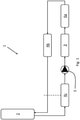
- FIG. 1 schematically shows a cooling system 1 according to a first embodiment of the disclosure.
- the cooling system 1 comprises a cooling system radiator 2 located behind a grill of a vehicle and in front of the vehicle's main radiators/condensers.
- the cooling system radiator 2 is thermodynamically connected to an on-board charger 3 and one or more vehicle components 4 such as a combined inverter and DC/DC converter 4a or an electric motor 4b.
- An internal flow of cooling liquid is pumped through each of the on-board charger 3 and the vehicle components 4 by a cooling fluid pump 5 to provide cooling.
- External airflow over the cooling system radiator 2 that cools the cooling liquid is driven by ram pressure and/or by a cool pack fan (not shown).
- the cooling system 1 may also comprise an expansion tank 4c.
- the cooling system 1 provides cooling to the vehicle components 4 during driving and to the on-board charger 3 when the vehicle is standing still during charging.
- the cooling system 1 is designed so that cooling fluid will flow through the cooling system 1 even if one or more of the parts of the cooling system 1 do not need cooling.
- the on-board charger 3 can be regarded as purely passive even though cooling fluid is continuously pumped through it when the cooling fluid pump 5 is engaged.
- the cooling system 1 has a maximum operating temperature of about 65-75 °C and by equipping the on-board charger 3 with a heat exchanging arrangement, the on-board charger 3 due to its usage, design and placement in the engine compartment can be utilized as an additional heat exchanger during driving. By making small changes to the on-board charger 3, it can be turned to a heat exchanger providing additional cooling power to cool one or more vehicle components 4 during driving. By doing so, the fan and pump usage during electric drive is lowered and some of the parasitic losses in the vehicle's systems can be cancelled.
- an airflow generated from the vehicle moving is arranged to flow over the heat exchanging arrangement.
- FIG. 2 schematically shows a perspective view of an on-board charger 3 according to the disclosure.
- the on-board charger 3 shown is an on-board charger used today modified for the additional cooling.
- the on-board charger 3 comprises a housing 6, a housing lid 7 and various electrical and fluid connections 8.
- internal cooling ducts 3a run close to an outer surface of the housing 6.
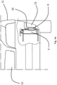
- FIG 3 schematically shows an on-board charger 3 where the housing lid 7 has been equipped with a heat exchanging arrangement 9.
- the housing lid 7 on a front side 10 of the on-board charger 3 of figure 2 is now provided with a heat exchanging arrangement 9 such that the cooling liquid inside the internal cooling ducts 3a much more efficiently can exchange heat with the cooler ambient air.
- the heat exchanging arrangement 9 is exemplified by several cooling fins. Other alternatives could be various kinds of cooling flanges.
- the heat exchanging arrangement 9 is in one alternative configuration a passive heat exchanging arrangement meaning that the heat exchanging arrangement 9 is not cooled by anything besides an airflow generated from the vehicle moving flows over the heat exchanging arrangement 9.
- the heat exchanging arrangement 9 is an active heat exchanging arrangement, wherein the cooling flange or cooling fins is arranged to also be provided with a coolant medium, meaning that additional cooling can be provided to the heat exchanging arrangement on the housing lid of the on-board charger.
- Figure 4a schematically shows a front view of a vehicle 11 displaying an on-board charger 3 of the cooling system 1 in a first location.
- the on-board charger 3 is placed in the lower right front part of the vehicle 11, parallel to a grill 12 of the vehicle 11, but separated from the airflow generated through the grill 12. It is also placed right next to an air channel 13 currently used to create an air curtain over a front tire for drag reduction.
- a front side 10 of the housing 6 of the on-board charger 3 is oriented forward, perpendicular to the direction of the vehicle ram flow, i.e. the front side 10 faces the direction of the vehicle ram flow.
- the on-board charger 3 is oriented such that the front side 10 of the on-board charger 3 is placed parallel to the direction of the vehicle ram flow, i.e. the front side 10 faces the left of the vehicle 11. With this orientation, the front side 10 of the on-board charger 3 now faces the air channel 13 instead of facing forward. As can be seen from the figure, this allows the heat exchanging arrangement 9 to extend into the air channel 13.
- airfrom the air channel 13 can be diverted over the heat exchanging arrangement 9 to provide cooling to the heat exchanging arrangement 9.
- the on-board charger 3 can be oriented with the front side 10 facing forward.
- Figure 4b schematically shows a side view of a vehicle 11 displaying an on-board charger 3 of the cooling system 1 in a first location.
- the heat exchanging arrangement 9 interacts with the air channel 13.
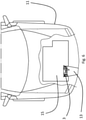
- Figure 4c schematically shows a top view of a vehicle 11 displaying an on-board charger 3 of the cooling system 1 in a first location. In this figure, the orientation of the on-board charger 3 can clearly be seen.
- Figure 5 schematically shows a front view of a vehicle 11 displaying an on-board charger 3 of the cooling system 1 in a second location.
- the on-board charger 3 is placed adjacent a main radiator 14, i.e. the radiator used for e.g. the air conditioning.
- An air channel 13 that uses the air that flows past the main radiator 14 is provided to direct air over the on-board charger 3.
- the on-board charger 3 is facing forward, with the front side 10 perpendicular to the ram airflow direction. It is also possible in this second location to orient the on-board charger 3 such that the front side 10 is parallel to the ram airflow direction.
- Figure 6 schematically shows a top view of a vehicle 11 displaying an on-board charger 3 of the cooling system 1 in a third location.
- the on-board charger 3 is located under a lower engine under shield 15, sometimes called lower engine splash shield. This means that the on-board charger 3 is placed between the engine and the lower engine under shield 15.
- One or more openings (not shown) in the lower engine under shield 15 can be directed into an air channel 13 that directs air past the on-board charger 3.
- the on-board charger 3 can be situated close to the openings such that no air channel 13 is required.
- the airflow going over the on-board charger will not be directly affected by warm air from the main cooling system or from the engine compartment and will therefore be that of ambient temperature.
- the cooling fluid temperature in the on-board charger will for strained scenarios match that of the requirement for the combined inverter DC/DC converter or electric motor, i.e. 65-75 °C. A high temperature delta between the ambient air and the cooling fluid can therefore be expected.
- FIG. 7 schematically shows a cooling system 1 according to a second embodiment of the disclosure.
- the on-board charger 3 is placed between the cooling system radiator 2 and the vehicle components 4. In this way, the total cooling power of the cooling system 1 can be increased further.
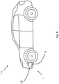
- Figure 8 schematically shows the vehicle 11 comprising a cooling system 1 according to the disclosure.
Landscapes
- Engineering & Computer Science (AREA)
- Mechanical Engineering (AREA)
- Transportation (AREA)
- Power Engineering (AREA)
- Chemical & Material Sciences (AREA)
- Combustion & Propulsion (AREA)
- Physics & Mathematics (AREA)
- Thermal Sciences (AREA)
- Cooling, Air Intake And Gas Exhaust, And Fuel Tank Arrangements In Propulsion Units (AREA)
- Electric Propulsion And Braking For Vehicles (AREA)
Abstract
The disclosure relates to a method for increased cooling power of a vehicle component (4) and a cooling system (1) for an electric vehicle (11). The cooling system (1) comprises an on-board charger (3) in cooling fluid connection with a cooling fluid pump (5), a cooling system radiator (2) and a vehicle component (4). The on-board charger (3) comprises a heat exchanging arrangement (9) arranged on a housing (6) of the on-board charger (3). When an airflow generated from the vehicle (11) moving flows over the heat exchanging arrangement (9), the heat exchanging arrangement (9) is arranged to cool a cooling fluid pumped through the on-board charger (3) by means of heat exchange between the cooling fluid and the airflow, thereby increasing the cooling of the vehicle component (4).
Description
- The disclosure relates to a cooling system for an electric vehicle. The cooling system comprises an on-board charger in cooling fluid connection with a cooling fluid pump, a cooling system radiator and a vehicle component. The disclosure also relates to a method for increased cooling power of a vehicle component.
- Electrified vehicles running on stored battery power must finely balance the amount of charge there is in the battery, how much power is used to propel the vehicle, how much is used for auxiliary systems and what is lost in pure energy loss. This balancing directly affect the electric vehicle's range. The energy consumption by the auxiliary systems ranges from about 200 to 800 W (normal to low use), depending on test cycle, conditions and vehicle.
- Electric vehicles capable of being charged by an external power source uses an on-board charger to charge the battery from the external power source. The on-board charger is connected to a cooling circuit that cools the electric motor and the combined inverter DC/DC when driving and the on-board charger during charging. The cooling circuit is designed in such a way that cooling liquid flows through the components even during times when they do not need cooling.
-
US 6,094,927 discloses a cooling circuit where the batteries and other electrical components can be cooled by an electric fan. A fan, however, requires power to run and will thereby affect the range of the vehicle. - An objective of the disclosure is to provide a cooling system and a method for increased cooling power of a vehicle component. The objective is achieved by the cooling system of
claim 1 and the method ofclaim 12. Dependent claims provide advantageous embodiments. - The disclosure relates to a cooling system for an electric vehicle. The cooling system comprises an on-board charger in cooling fluid connection with a cooling fluid pump, a cooling system radiator and a vehicle component. The on-board charger comprises a heat exchanging arrangement arranged on a housing of the on-board charger. When an airflow generated from the vehicle moving flows over the heat exchanging arrangement, the heat exchanging arrangement is arranged to cool a cooling fluid pumped through the on-board charger by means of heat exchange between the cooling fluid and the airflow.
- One advantage with the cooling system according to the disclosure is that is increases the cooling of the vehicle component. The vehicle component is for instance an electric motor and/or a combined inverter and DC/DC converter.
- In electric vehicles, a cooling system is arranged to cool down various vehicle components during drive as well as the on-board charger when standing still during charge. The cooling system is designed such that cooling fluid flows through said vehicle components even if one does not need cooling. The on-board charger is today regarded as a pure passive component during driving but cooling fluid is still pumped through it when the cooling fluid pump is engaged. The way the on-board charger is used today, leaving it passive during driving, adapting the on-board charger for exchanging heat between the cooling fluid that runs inside the on-board charger and ambient air flowing past the on-board charger due to the motion of the vehicle during driving improves the overall cooling effect in the cooling system.
- The on-board charger may be arranged in connection to an air channel and the airflow is a ram airflow generated in the air channel from the vehicle moving, wherein the ram airflow is directed to flow over the heat exchanging arrangement via openings in the air channel, and/or wherein at least a part of the heat exchanging arrangement extends into the ram airflow in the air channel such that the ram air flow flows over the heat exchanging arrangement.
- The on-board charger is normally located in a low temperature zone in the vehicle, close to an air channel. Modifying the on-board charger to be arranged in connection to an air channel, the on-board charger's material properties and the orientation of the internal cooling channels in the on-board charger makes ram airflow a suitable way to transport air with a cooler temperature than the cooling fluid inside the on-board charger. In this way, an efficient cooling can be achieved.
- The heat exchanging arrangement may be arranged on a housing lid of the on-board charger.
- By arranging the heat exchanging arrangement on a housing lid of the on-board charger, i.e. on a front side of the on-board charger, the heat exchanging arrangement will in an easy way, provide the on-board charger with a heat exchanging ability without having to change the on-board charger internally. Inside the on-board charger, superficial internal cooling ducts run making the distance between the outside of the housing and the internal cooling ducts small. By installing the heat exchanging arrangement on the housing lid, the heat exchanging arrangement can be easily replaced and no need of any changes to component of the on-board charger is required. Accessing the interior of the on-board charger is not affected.
- The heat exchanging arrangement may comprise a cooling flange or cooling fins.
- Different types of heat exchanging arrangements may be provided in order to make the on-board charger function as a heat exchanger. A cooling flange or cooling fins are two examples, but other alternatives are of course possible.
- The on-board charger may be arranged essentially parallel to a grill of the vehicle and the air channel is an air channel arranged to create an air curtain over a front tire.
- One alternative location for the on-board charger is to essentially keep in a position where it is located today. With minor modifications to the on-board chargers orientation and position, an existing air channel arranged to create an air curtain over a front tire can also be used to provide ram airflow over the on-board charger to provide cooling.
- The on-board charger may be arranged adjacent a main radiator and the air channel is an air channel arranged to direct air over the main radiator.
- A further alternative location for the on-board charger could be to place the on-board charger adjacent the vehicle's main radiator, i.e. the radiator that is used to provide cooling/heating for e.g. the vehicle's air conditioning. In this position, the air channel providing the ram airflow over the on-board charger is either the air channel arranged to direct air over the main radiator or a by-pass air channel directing air from the air channel arranged to direct air over the main radiator.
- The on-board charger may be arranged under a lower engine under shield of the vehicle and the air channel is an air channel in the lower engine under shield.
- A further alternative location for the on-board charger could be to place the on-board charger under a lower engine under shield of the vehicle and forming an air channel in the lower engine under shield to provide the ram airflow over the on-board charger.
- The on-board charger may be arranged between the vehicle component and the cooling system radiator in the cooling system.
- In order to further improve the cooling effect, the on-board charger could be placed between the vehicle component and the cooling system radiator in the cooling system. This would put the on-board charger before the cooling system radiator, thereby leading to the greatest total cooling effect of the cooling system.
- The heat exchanging arrangement may be a passive heat exchanging arrangement.
- In one alternative embodiment, the heat exchanging arrangement may be a passive heat exchanging arrangement meaning that the heat exchanging arrangement is not cooled by anything besides an airflow generated from the vehicle moving flows over the heat exchanging arrangement.
- The heat exchanging arrangement may be an active heat exchanging arrangement, wherein the cooling flange or cooling fins is arranged to also be provided with a coolant medium.
- As an alternative to a passive heat exchanging arrangement, the heat exchanging arrangement may be an active heat exchanging arrangement, meaning that additional cooling is provided to the heat exchanging arrangement on the housing lid of the on-board charger. A coolant medium with a temperature lower than the cooling fluid inside the on-board charger could be provided to the active heat exchanging arrangement, thereby leading to an increase in cooling effect. The coolant medium could be provided from for instance the air conditioning cooling system, the battery cooling system or another cooling system of the vehicle.
- The disclosure also relates to a vehicle comprising a cooling system according to the above description.
- The disclosure also relates to a method for increased cooling power of a vehicle component, wherein a cooling system comprises an on-board charger in cooling fluid connection with a cooling fluid pump, a cooling system radiator and the vehicle component, wherein the method comprises:
- providing the on-board charger with a heat exchanging arrangement arranged on a housing of the on-board charger,
- generating an airflow from the vehicle moving arranged to flow over the heat exchanging arrangement,
- cooling a cooling fluid passing through the on-board charger by means of heat exchange between the cooling fluid and the airflow flowing over the heat exchanging arrangement.
- The method may also comprise:
- arranging the on-board charger in connection to an air channel,
- generating a ram airflow in the air channel from the vehicle moving,
- directing the ram airflow to flow over the heat exchanging arrangement via openings in the air channel, and/or
- arranging at least a part of the heat exchanging arrangement to extend into the ram airflow in the air channel such that the ram air flow flows over the heat exchanging arrangement.
- The method may also comprise:
- arranging the heat exchanging arrangement on a housing lid of the on-board charger.
- The method may also comprise:
- arranging a cooling flange or cooling fins as the heat exchanging arrangement.
- The advantages with the method are the same as for the cooling system described above.
-
-
Figure 1 schematically shows cooling system according to a first embodiment of the disclosure, -
Figure 2 schematically shows a cut-away view of an on-board charger, -
Figure 3 schematically shows an on-board charger where a housing lid comprises a heat exchanging arrangement, -
Figure 4a schematically shows a front view of a vehicle displaying an on-board charger of the cooling system in a first location, -
Figure 4b schematically shows a side view of a vehicle displaying an on-board charger of the cooling system in a first location, -
Figure 4c schematically shows a top view of a vehicle displaying an on-board charger of the cooling system in a first location, -
Figure 5 schematically shows a front view of a vehicle displaying an on-board charger of the cooling system in a second location, -
Figure 6 schematically shows a top view of a vehicle displaying an on-board charger of the cooling system in a third location, -
Figure 7 schematically shows cooling system according to a second embodiment of the disclosure, -
Figure 8 schematically shows a vehicle comprising a cooling system according to the disclosure. - Within the context of the disclosure, an electric vehicle includes all kinds of electric vehicles that can be charged from an external power source, including plug-in electric vehicles and plug-in hybrid electric vehicles.
-
Figure 1 schematically shows acooling system 1 according to a first embodiment of the disclosure. Thecooling system 1 comprises acooling system radiator 2 located behind a grill of a vehicle and in front of the vehicle's main radiators/condensers. Thecooling system radiator 2 is thermodynamically connected to an on-board charger 3 and one or more vehicle components 4 such as a combined inverter and DC/DC converter 4a or anelectric motor 4b. An internal flow of cooling liquid is pumped through each of the on-board charger 3 and the vehicle components 4 by a coolingfluid pump 5 to provide cooling. External airflow over the coolingsystem radiator 2 that cools the cooling liquid is driven by ram pressure and/or by a cool pack fan (not shown). Thecooling system 1 may also comprise anexpansion tank 4c. - The
cooling system 1 provides cooling to the vehicle components 4 during driving and to the on-board charger 3 when the vehicle is standing still during charging. Thecooling system 1 is designed so that cooling fluid will flow through thecooling system 1 even if one or more of the parts of thecooling system 1 do not need cooling. During driving of the electric vehicle, the on-board charger 3 can be regarded as purely passive even though cooling fluid is continuously pumped through it when the coolingfluid pump 5 is engaged. - The
cooling system 1 has a maximum operating temperature of about 65-75 °C and by equipping the on-board charger 3 with a heat exchanging arrangement, the on-board charger 3 due to its usage, design and placement in the engine compartment can be utilized as an additional heat exchanger during driving. By making small changes to the on-board charger 3, it can be turned to a heat exchanger providing additional cooling power to cool one or more vehicle components 4 during driving. By doing so, the fan and pump usage during electric drive is lowered and some of the parasitic losses in the vehicle's systems can be cancelled. - To assist with the cooling, an airflow generated from the vehicle moving is arranged to flow over the heat exchanging arrangement.
-
Figure 2 schematically shows a perspective view of an on-board charger 3 according to the disclosure. The on-board charger 3 shown is an on-board charger used today modified for the additional cooling. The on-board charger 3 comprises ahousing 6, ahousing lid 7 and various electrical andfluid connections 8. As can be seen from the figure, internal cooling ducts 3a run close to an outer surface of thehousing 6. -
Figure 3 schematically shows an on-board charger 3 where thehousing lid 7 has been equipped with aheat exchanging arrangement 9. Infigure 3 , thehousing lid 7 on afront side 10 of the on-board charger 3 offigure 2 is now provided with aheat exchanging arrangement 9 such that the cooling liquid inside the internal cooling ducts 3a much more efficiently can exchange heat with the cooler ambient air. Infigure 3 , theheat exchanging arrangement 9 is exemplified by several cooling fins. Other alternatives could be various kinds of cooling flanges. - The
heat exchanging arrangement 9 is in one alternative configuration a passive heat exchanging arrangement meaning that theheat exchanging arrangement 9 is not cooled by anything besides an airflow generated from the vehicle moving flows over theheat exchanging arrangement 9. - In a second alternative configuration (not shown), the
heat exchanging arrangement 9 is an active heat exchanging arrangement, wherein the cooling flange or cooling fins is arranged to also be provided with a coolant medium, meaning that additional cooling can be provided to the heat exchanging arrangement on the housing lid of the on-board charger. -
Figure 4a schematically shows a front view of avehicle 11 displaying an on-board charger 3 of thecooling system 1 in a first location. As shown in the picture, the on-board charger 3 is placed in the lower right front part of thevehicle 11, parallel to agrill 12 of thevehicle 11, but separated from the airflow generated through thegrill 12. It is also placed right next to anair channel 13 currently used to create an air curtain over a front tire for drag reduction. Normally, afront side 10 of thehousing 6 of the on-board charger 3 is oriented forward, perpendicular to the direction of the vehicle ram flow, i.e. thefront side 10 faces the direction of the vehicle ram flow. In this embodiment, the on-board charger 3 is oriented such that thefront side 10 of the on-board charger 3 is placed parallel to the direction of the vehicle ram flow, i.e. thefront side 10 faces the left of thevehicle 11. With this orientation, thefront side 10 of the on-board charger 3 now faces theair channel 13 instead of facing forward. As can be seen from the figure, this allows theheat exchanging arrangement 9 to extend into theair channel 13. - Alternatively, airfrom the
air channel 13 can be diverted over theheat exchanging arrangement 9 to provide cooling to theheat exchanging arrangement 9. In this case, the on-board charger 3 can be oriented with thefront side 10 facing forward. -
Figure 4b schematically shows a side view of avehicle 11 displaying an on-board charger 3 of thecooling system 1 in a first location. In this figure, it can more clearly be seen how theheat exchanging arrangement 9 interacts with theair channel 13. -
Figure 4c schematically shows a top view of avehicle 11 displaying an on-board charger 3 of thecooling system 1 in a first location. In this figure, the orientation of the on-board charger 3 can clearly be seen. -
Figure 5 schematically shows a front view of avehicle 11 displaying an on-board charger 3 of thecooling system 1 in a second location. In the second location, the on-board charger 3 is placed adjacent amain radiator 14, i.e. the radiator used for e.g. the air conditioning. Anair channel 13 that uses the air that flows past themain radiator 14 is provided to direct air over the on-board charger 3. In the example offigure 5 , the on-board charger 3 is facing forward, with thefront side 10 perpendicular to the ram airflow direction. It is also possible in this second location to orient the on-board charger 3 such that thefront side 10 is parallel to the ram airflow direction. -
Figure 6 schematically shows a top view of avehicle 11 displaying an on-board charger 3 of thecooling system 1 in a third location. In this location, the on-board charger 3 is located under a lower engine undershield 15, sometimes called lower engine splash shield. This means that the on-board charger 3 is placed between the engine and the lower engine undershield 15. One or more openings (not shown) in the lower engine undershield 15 can be directed into anair channel 13 that directs air past the on-board charger 3. Alternatively, the on-board charger 3 can be situated close to the openings such that noair channel 13 is required. - In all three positions described above, the airflow going over the on-board charger will not be directly affected by warm air from the main cooling system or from the engine compartment and will therefore be that of ambient temperature. The cooling fluid temperature in the on-board charger will for strained scenarios match that of the requirement for the combined inverter DC/DC converter or electric motor, i.e. 65-75 °C. A high temperature delta between the ambient air and the cooling fluid can therefore be expected.
-
Figure 7 schematically shows acooling system 1 according to a second embodiment of the disclosure. In this embodiment, the on-board charger 3 is placed between the coolingsystem radiator 2 and the vehicle components 4. In this way, the total cooling power of thecooling system 1 can be increased further. -
Figure 8 schematically shows thevehicle 11 comprising acooling system 1 according to the disclosure. - Although the disclosure has been illustrated and described in detail in the drawings and foregoing description, such illustration and description are to be considered illustrative or exemplary and the disclosure is not limited to the disclosed example embodiments.
-
- 1.
- Cooling system
- 2.
- Cooling system radiator
- 3.
- On-board charger
a. Internal cooling ducts - 4.
- Vehicle component
a. Combined inverter and DC/DC converter
b. Electric motor - 5.
- Cooling fluid pump
- 6.
- Housing
- 7.
- Housing lid
- 8.
- Connections
- 9.
- Heat exchanging arrangement
- 10.
- Front side
- 11.
- Vehicle
- 12.
- Grill
- 13.
- Air channel
- 14.
- Main radiator
- 15.
- Lower engine under shield
Claims (15)
- Cooling system (1) for an electric vehicle (11), wherein the cooling system (1) comprises an on-board charger (3) in cooling fluid connection with a cooling fluid pump (5), a cooling system radiator (2) and at least one vehicle component (4), characterized in that the on-board charger (3) comprises a heat exchanging arrangement (9) arranged on a housing (6) of the on-board charger (3), wherein, when an airflow generated from the vehicle (11) moving flows over the heat exchanging arrangement (9), the heat exchanging arrangement (9) is arranged to cool a cooling fluid pumped through the on-board charger (3) by means of heat exchange between the cooling fluid and the airflow, thereby increasing the cooling of the vehicle component (4).
- Cooling system (1) according to claim 1, wherein the on-board charger (3) is arranged in connection to an air channel (13) and the airflow is a ram airflow generated in the air channel (13) from the vehicle (11) moving, wherein the ram airflow is directed to flow over the heat exchanging arrangement (9) via openings in the air channel (13), and/or wherein at least a part of the heat exchanging arrangement (9) extends into the ram airflow in the air channel (13) such that the ram air flow flows over the heat exchanging arrangement (9).
- Cooling system (1) according to claim 1 or 2, wherein the heat exchanging arrangement (9) is arranged on a housing lid (7) of the on-board charger (3).
- Cooling system (1) according to any one of the preceding claims, wherein the heat exchanging arrangement (9) comprises a cooling flange or cooling fins.
- Cooling system (1) according to any one of the preceding claims 2-4, wherein the on-board charger (3) is arranged essentially parallel to a grill (12) of the vehicle (11) and the air channel (13) is an air channel (13) arranged to create an air curtain over a front tire.
- Cooling system (1) according to any one of the preceding claims 2-4, wherein the on-board charger (3) is arranged adjacent a main radiator (14) and the air channel (13) is an air channel (13) arranged to direct air over the main radiator (14).
- Cooling system (1) according to any one of the preceding claims 2-4, wherein the on-board charger (3) is arranged under a lower engine under shield (15) of the vehicle (11) and the air channel (13) is an air channel (13) in the lower engine under shield (15).
- Cooling system (1) according to any one of the preceding claims, wherein the on-board charger (3) is arranged between the vehicle component (4) and the cooling system radiator (2) in the cooling system (1).
- Cooling system (1) according to any one of the preceding claims, wherein the heat exchanging arrangement (9) is a passive heat exchanging arrangement (9).
- Cooling system (1) according to any one of the preceding claims, wherein the heat exchanging arrangement (9) is an active heat exchanging arrangement (9), wherein the cooling flange or cooling fins is arranged to also be provided with a coolant medium.
- Vehicle (11) comprising a cooling system (1) according to the preceding claims.
- Method for increased cooling power of a vehicle component (4), wherein a cooling system (1) comprises an on-board charger (3) in cooling fluid connection with a cooling fluid pump (5), a cooling system radiator (2) and the vehicle component (4), wherein the method comprises:- providing the on-board charger (3) with a heat exchanging arrangement (9) arranged on a housing (6) of the on-board charger (3),- generating an airflow from the vehicle (11) moving arranged to flow over the heat exchanging arrangement (9),- cooling a cooling fluid passing through the on-board charger (3) by means of heat exchange between the cooling fluid and the airflow flowing over the heat exchanging arrangement (9).
- Method according to claim 12, wherein the method comprises:- arranging the on-board charger (3) in connection to an air channel (13),- generating a ram airflow in the air channel (13) from the vehicle (11) moving,- directing the ram airflow to flow over the heat exchanging arrangement (9) via openings in the air channel (13), and/or- arranging at least a part of the heat exchanging arrangement (9) to extend into the ram airflow in the air channel (13) such that the ram air flow flows over the heat exchanging arrangement (9).
- Method according to any one of claims 12-13, wherein the method comprises:- arranging the heat exchanging arrangement (9) on a housing lid (7) of the on-board charger (3).
- Method according to any one of claims 12-14, wherein the method comprises:- arranging a cooling flange or cooling fins as the heat exchanging arrangement (9).
Priority Applications (4)
| Application Number | Priority Date | Filing Date | Title |
|---|---|---|---|
| EP20193710.9A EP3960525A1 (en) | 2020-08-31 | 2020-08-31 | Cooling system for an electric vehicle |
| PCT/CN2021/114471 WO2022042582A1 (en) | 2020-08-31 | 2021-08-25 | Cooling system for an electric vehicle |
| CN202180044466.XA CN115702605A (en) | 2020-08-31 | 2021-08-25 | Cooling system for electric vehicle |
| US18/074,463 US20230100546A1 (en) | 2020-08-31 | 2022-12-03 | Cooling system for an electric vehicle |
Applications Claiming Priority (1)
| Application Number | Priority Date | Filing Date | Title |
|---|---|---|---|
| EP20193710.9A EP3960525A1 (en) | 2020-08-31 | 2020-08-31 | Cooling system for an electric vehicle |
Publications (1)
| Publication Number | Publication Date |
|---|---|
| EP3960525A1 true EP3960525A1 (en) | 2022-03-02 |
Family
ID=72292436
Family Applications (1)
| Application Number | Title | Priority Date | Filing Date |
|---|---|---|---|
| EP20193710.9A Pending EP3960525A1 (en) | 2020-08-31 | 2020-08-31 | Cooling system for an electric vehicle |
Country Status (4)
| Country | Link |
|---|---|
| US (1) | US20230100546A1 (en) |
| EP (1) | EP3960525A1 (en) |
| CN (1) | CN115702605A (en) |
| WO (1) | WO2022042582A1 (en) |
Families Citing this family (3)
| Publication number | Priority date | Publication date | Assignee | Title |
|---|---|---|---|---|
| EP4247664A4 (en) * | 2020-11-17 | 2024-05-29 | Tritium Holdings Pty Ltd | KIT FOR AN ELECTRIC VEHICLE CHARGER |
| JP2025040480A (en) * | 2023-09-12 | 2025-03-25 | 三菱電機モビリティ株式会社 | Electric vehicle drive unit |
| US12600216B2 (en) * | 2023-10-13 | 2026-04-14 | Kubota Corporation | Electric motor supporting arrangement for vehicles |
Citations (3)
| Publication number | Priority date | Publication date | Assignee | Title |
|---|---|---|---|---|
| US6094927A (en) | 1997-12-18 | 2000-08-01 | Honda Giken Kogyo Kabushiki Kaisha | Cooling structure an electric vehicle |
| US20180066576A1 (en) * | 2015-02-13 | 2018-03-08 | Ford Global Technologies, Llc | Turbocharger system having an air-cooled wastegate actuator |
| US20190263280A1 (en) * | 2018-02-26 | 2019-08-29 | AitronX Inc. | Onboard Charger Heat Dissipation |
Family Cites Families (20)
| Publication number | Priority date | Publication date | Assignee | Title |
|---|---|---|---|---|
| JPS5162438A (en) * | 1974-11-27 | 1976-05-31 | Masahiro Morita | Kyusokutoketsusochi |
| US6148618A (en) * | 1997-04-25 | 2000-11-21 | Frigoscandia Equipment Ab | Method and apparatus for surface freezing |
| KR101375956B1 (en) * | 2012-07-05 | 2014-03-18 | 엘에스산전 주식회사 | Electronic component box for vehicle |
| KR101795080B1 (en) * | 2012-12-17 | 2017-11-08 | 현대자동차주식회사 | System and method for charging battery of vehicle |
| CN204648736U (en) * | 2015-04-13 | 2015-09-16 | 福建雪人股份有限公司 | A kind of CO 2/ NH 3folding type cooling system |
| US9744848B2 (en) * | 2015-12-21 | 2017-08-29 | Thunder Power New Energy Vehicle Development Company Limited | Vehicle radiator V type layout |
| KR101786350B1 (en) * | 2016-05-26 | 2017-11-16 | 현대자동차주식회사 | Charging system for plug-in hybrid vehicle and method of controlling the same |
| KR20180056027A (en) * | 2016-11-18 | 2018-05-28 | 현대자동차주식회사 | Cooling system of hybrid vehicle having variable path for improving efficiency |
| CN109551992A (en) * | 2017-09-06 | 2019-04-02 | 昶洧新能源汽车发展有限公司 | Front end air flow for cooling system |
| CN108016837A (en) * | 2017-12-21 | 2018-05-11 | 重庆渝黔电力发展有限责任公司 | Building material conveyer |
| WO2019180820A1 (en) * | 2018-03-20 | 2019-09-26 | 三菱電機株式会社 | In-vehicle battery charger |
| US10941695B2 (en) * | 2018-07-10 | 2021-03-09 | Volvo Car Corporation | System for cooling heat-generating electronic components of a vehicle |
| CN208499614U (en) * | 2018-07-10 | 2019-02-15 | 聊城东大食品有限公司 | A kind of quick-frozen discharging device of Delicious meat |
| CN109081097A (en) * | 2018-08-27 | 2018-12-25 | 安徽省皖美食品有限公司 | A kind of anti-sticking twirl conveying device of quick-frozen food |
| KR102554926B1 (en) * | 2018-12-05 | 2023-07-11 | 현대자동차주식회사 | Method for charging battery at low temperature |
| CN210537232U (en) * | 2019-09-25 | 2020-05-15 | 苏州清盛汽车技术有限公司 | On-vehicle heat abstractor for machine that charges of OBC |
| CN210869695U (en) * | 2019-10-24 | 2020-06-30 | 江苏荣泽食品有限公司 | Continuous immersion type fruit and vegetable food quick-freezing tunnel |
| CN212179323U (en) * | 2020-04-15 | 2020-12-18 | 南京年吉冷冻食品有限公司 | Energy-efficient meat products quick-freeze equipment |
| CN112665310A (en) * | 2021-01-14 | 2021-04-16 | 上海海洋大学 | Ultrasonic rapid freezing equipment with vortex tube and freezing method |
| CN217154633U (en) * | 2022-02-28 | 2022-08-09 | 上海奥本食品有限公司 | Liquid nitrogen instant freezer |
-
2020
- 2020-08-31 EP EP20193710.9A patent/EP3960525A1/en active Pending
-
2021
- 2021-08-25 CN CN202180044466.XA patent/CN115702605A/en active Pending
- 2021-08-25 WO PCT/CN2021/114471 patent/WO2022042582A1/en not_active Ceased
-
2022
- 2022-12-03 US US18/074,463 patent/US20230100546A1/en not_active Abandoned
Patent Citations (3)
| Publication number | Priority date | Publication date | Assignee | Title |
|---|---|---|---|---|
| US6094927A (en) | 1997-12-18 | 2000-08-01 | Honda Giken Kogyo Kabushiki Kaisha | Cooling structure an electric vehicle |
| US20180066576A1 (en) * | 2015-02-13 | 2018-03-08 | Ford Global Technologies, Llc | Turbocharger system having an air-cooled wastegate actuator |
| US20190263280A1 (en) * | 2018-02-26 | 2019-08-29 | AitronX Inc. | Onboard Charger Heat Dissipation |
Also Published As
| Publication number | Publication date |
|---|---|
| CN115702605A (en) | 2023-02-14 |
| US20230100546A1 (en) | 2023-03-30 |
| WO2022042582A1 (en) | 2022-03-03 |
Similar Documents
| Publication | Publication Date | Title |
|---|---|---|
| US20230100546A1 (en) | Cooling system for an electric vehicle | |
| US10476051B2 (en) | Battery pack base plate heat exchanger | |
| US11794547B2 (en) | Integrated thermal management module for vehicle | |
| US11305611B2 (en) | Air-conditioning apparatus for vehicle | |
| KR102706248B1 (en) | Thermal management system for vehicle | |
| US11541725B2 (en) | Thermal management system and integrated thermal management module for vehicle | |
| JP5436673B2 (en) | Vehicle comprising at least one cooling circuit for cooling a fuel cell system | |
| US7455136B2 (en) | Cooling system for a rearward portion of a vehicle and method of cooling | |
| US9250020B2 (en) | Active louver system for controlled airflow in a multi-function automotive radiator and condenser system | |
| US20120168125A1 (en) | Multi-Function Automotive Radiator and Condenser Airflow System | |
| US20200171913A1 (en) | Thermal management system for vehicle | |
| US20210010766A1 (en) | Drive Train Assembly Thermal Management System | |
| CN102689586A (en) | Integral temperature control system for electric automobile | |
| CN114502403B (en) | Cooling equipment for motor vehicles | |
| US20250135869A1 (en) | Vehicle with coupled cooling circuits for cooling an electrochemical cell | |
| JP4323307B2 (en) | Vehicle heat exchanger system | |
| JP2013079614A (en) | Cooling apparatus for hybrid vehicle with supercharger | |
| US20220069385A1 (en) | Temperature adjustment circuit | |
| JP2024079081A (en) | Cooling System | |
| US20250153559A1 (en) | Powertrain and mechanical device | |
| US11552350B2 (en) | Vehicle battery pack | |
| EP4624226A1 (en) | Electric drive device for vehicle | |
| EP4461576A2 (en) | Vehicle cooling system and vehicle | |
| WO2024225210A1 (en) | Vehicle drive device | |
| KR102948590B1 (en) | Cooling module for vehicle |
Legal Events
| Date | Code | Title | Description |
|---|---|---|---|
| PUAI | Public reference made under article 153(3) epc to a published international application that has entered the european phase |
Free format text: ORIGINAL CODE: 0009012 |
|
| STAA | Information on the status of an ep patent application or granted ep patent |
Free format text: STATUS: REQUEST FOR EXAMINATION WAS MADE |
|
| 17P | Request for examination filed |
Effective date: 20200831 |
|
| AK | Designated contracting states |
Kind code of ref document: A1 Designated state(s): AL AT BE BG CH CY CZ DE DK EE ES FI FR GB GR HR HU IE IS IT LI LT LU LV MC MK MT NL NO PL PT RO RS SE SI SK SM TR |