EP3960508A1 - System for connecting a trailer and a truck - Google Patents
System for connecting a trailer and a truck Download PDFInfo
- Publication number
- EP3960508A1 EP3960508A1 EP20795332.4A EP20795332A EP3960508A1 EP 3960508 A1 EP3960508 A1 EP 3960508A1 EP 20795332 A EP20795332 A EP 20795332A EP 3960508 A1 EP3960508 A1 EP 3960508A1
- Authority
- EP
- European Patent Office
- Prior art keywords
- trailer
- attachment part
- drawbar
- truck
- support
- Prior art date
- Legal status (The legal status is an assumption and is not a legal conclusion. Google has not performed a legal analysis and makes no representation as to the accuracy of the status listed.)
- Granted
Links
Images



Classifications
-
- B—PERFORMING OPERATIONS; TRANSPORTING
- B60—VEHICLES IN GENERAL
- B60D—VEHICLE CONNECTIONS
- B60D1/00—Traction couplings; Hitches; Draw-gear; Towing devices
- B60D1/14—Draw-gear or towing devices characterised by their type
- B60D1/145—Draw-gear or towing devices characterised by their type consisting of an elongated single bar or tube
- B60D1/155—Draw-gear or towing devices characterised by their type consisting of an elongated single bar or tube comprising telescopic or foldable parts
-
- B—PERFORMING OPERATIONS; TRANSPORTING
- B60—VEHICLES IN GENERAL
- B60D—VEHICLE CONNECTIONS
- B60D1/00—Traction couplings; Hitches; Draw-gear; Towing devices
- B60D1/01—Traction couplings or hitches characterised by their type
- B60D1/02—Bolt or shackle-type couplings
-
- B—PERFORMING OPERATIONS; TRANSPORTING
- B60—VEHICLES IN GENERAL
- B60D—VEHICLE CONNECTIONS
- B60D1/00—Traction couplings; Hitches; Draw-gear; Towing devices
- B60D1/58—Auxiliary devices
- B60D1/66—Props
-
- B—PERFORMING OPERATIONS; TRANSPORTING
- B60—VEHICLES IN GENERAL
- B60D—VEHICLE CONNECTIONS
- B60D1/00—Traction couplings; Hitches; Draw-gear; Towing devices
- B60D1/14—Draw-gear or towing devices characterised by their type
- B60D1/145—Draw-gear or towing devices characterised by their type consisting of an elongated single bar or tube
-
- B—PERFORMING OPERATIONS; TRANSPORTING
- B60—VEHICLES IN GENERAL
- B60D—VEHICLE CONNECTIONS
- B60D1/00—Traction couplings; Hitches; Draw-gear; Towing devices
- B60D1/24—Traction couplings; Hitches; Draw-gear; Towing devices characterised by arrangements for particular functions
- B60D1/42—Traction couplings; Hitches; Draw-gear; Towing devices characterised by arrangements for particular functions for being adjustable
- B60D1/46—Traction couplings; Hitches; Draw-gear; Towing devices characterised by arrangements for particular functions for being adjustable vertically
- B60D1/465—Traction couplings; Hitches; Draw-gear; Towing devices characterised by arrangements for particular functions for being adjustable vertically comprising a lifting mechanism, e.g. for coupling while lifting
Definitions
- the present invention relates to a system for connecting a trailer and a truck which allows improving the truck loading operation with the trailer connected to the truck, therefore improving the efficiency of the assembly loading.
- the articulated-extendable system for connecting the trailer and the truck object of the invention is applicable in the logistics industry, namely in the road transport industry.
- the rigid nature of the system for connecting means that the truck and the trailer cannot be brought closer together without unhitching the drawbar connecting them together, which means that loading the trailer and the truck cannot be done in a continuous manner without that disconnection, and given that the unhitching is a complicated operation, it is not often done, but rather the trailer and the truck are loaded separately.
- patent document ES2049263 T3 discloses a short coupling with a variable geometry for trailers in which connection means with elastic memory are connected in a position of minimum spacing between the trailer and the truck, with two symmetrical supports for abutting and pivoting the front face of the trailer relative to the rear face of the truck at the level of each corner, around a vertical axis located as close as possible to each corner, in order to obtain a trajectory which clears the entire front face of the trailer when it is pivoted while turning a corner.
- patent document FR2636011A discloses a device for hitching a trailer and a trailer vehicle in particular having a drawbar mounted with the ability to move in a guided manner with respect to a fixed portion of the trailer, said drawbar being secured to a mechanism of the hydropneumatic type slaved by a control circuit by means of at least one sensor arranged level with the hitch to be urged or otherwise as a function of the angles between the towing vehicle and the trailer, both in a vertical and in horizontal plane.
- An object of the invention relates to a system for connecting a trailer with a loading platform and a truck with a loading platform, which comprises a drawbar configured to be attached to the truck and to the trailer.
- the drawbar comprises a first tubular body and a second tubular body with the ability to move linearly with respect to the first tubular body.
- the system comprises a first support comprising a drawbar attachment part and a trailer attachment part, such that between the drawbar attachment part and the trailer attachment part the first support comprises a rotation shaft for the drawbar, and it also comprises a second support comprising a drawbar attachment part and a trailer attachment part, and attachment means between the drawbar attachment part and the trailer attachment part.
- the system for connecting object of the invention further comprises a trailer-elevating mechanism configured for elevating the height of the trailer with respect to the ground.
- the system for connecting object of the invention when the drawbar attachment part and the trailer attachment part of the second support are not connected and the elevating mechanism is switched on, the system levels the height of the loading platforms of the truck and the trailer, and such that when the drawbar attachment part and the trailer attachment part of the second support are connected, the drawbar is connected to the trailer in a rigid manner, and when the trailer-elevating mechanism does not act, the system for connecting provides a connection between the trailer and truck under safe conditions for travel.
- the first tubular body comprises four flat parts identical to each other in pairs, which are connected configuring a box beam comprising a central housing having a complementary section relative to the second tubular body and two protrusions on each side of the central housing.
- the drawbar attachment part comprises two lugs connected by a lower plate and an upper plate in each side housing of the first tubular body, such that each upper plate comprises an opening;
- the trailer attachment part comprises a main beam with two side flats and a support element connected to the side flats, such that the support element comprises a frustoconical-shaped protrusion configured for being housed in the opening of the upper plate.
- the attachment means between the drawbar attachment part and the trailer attachment part of the second support comprise a pin configured for being introduced in a housing of the frustoconical-shaped protrusion of the support element of the trailer attachment part and abutting with the lower plate of the drawbar attachment part, such that with the frustoconical-shaped protrusion housed between the lower plate and the upper plate, the pin attaches the trailer attachment part to the drawbar attachment part.
- the attachment means between the drawbar attachment part and the trailer attachment part of the second support comprise pneumatic attachment means.
- the trailer-elevating mechanism comprises telescopic supports with the ability to rotate with respect to the trailer.
- the telescopic supports of the system for connecting a trailer and a truck object of the invention are to be chosen from pneumatic, hydraulic, mechanical, and a combination thereof.
- the system for connecting a trailer (1) and a truck (2) object of the invention comprises a drawbar (3) for connecting the truck (2) and the trailer (1), said drawbar (3) comprising a first tubular body (4) and a second tubular body (5) housed inside the first tubular body (4), such that the second tubular body (5) has ability to move linearly relative to the first tubular body (4), i.e., the drawbar (3) has a telescopic configuration.
- the first tubular body (4) comprises four flat parts identical to each other in pairs, which parts are connected forming a box beam, comprising:
- the system object of the invention comprises:
- the attachment of the drawbar (3) to the truck (2) is performed by attachment means known in the state of the art.
- the drawbar attachment part (13) comprises two lugs (15) connected by a lower plate (16) and an upper plate (17) in each side housing (8) of the first tubular body (4), such that each upper plate (17) comprises an opening (18).
- the trailer attachment part (14) comprises a main beam (19) with two side flats (20) and a support element (21) connected to the side flats (20) such that the support element (21) has a frustoconical-shaped protrusion (22) configured for being housed in the opening (18) of the upper plate (17).
- the attachment means (28) between the drawbar attachment part (13) and the trailer attachment part (14) of the second support (12) comprise a pin (24) which is introduced in a housing (25) of the frustoconical-shaped protrusion (22) of the support element (21) of the trailer attachment part (14) and abuts with the lower plate (16) of the drawbar attachment part (13), such that the frustoconical-shaped protrusion (22) is housed between the lower plate (16) and the upper plate (17) with the support element (21) against the upper plate (17) and the pin (24) attaching the trailer attachment part (14) to the drawbar attachment part (13).
- attachment means (28) between the drawbar attachment part (13) and the trailer attachment part (14) of the second support (12) comprise pneumatic attachment means which act similarly to the pin (24).
- the system object of the invention also comprises a trailer-elevating mechanism (26) configured for elevating the height of the trailer (1) with respect to the ground, such that the floor of the trailer (1) and the floor of the truck (2) are flush with one another.
- the trailer-elevating mechanism (26) comprises telescopic supports (27) with the ability to rotate with respect to the connection with the trailer (1).
- the telescopic supports (27) of the trailer-elevating mechanism (26) of the system object of the invention are to be chosen from pneumatic, hydraulic, mechanical, and a combination thereof.
- the system for connecting a truck and a trailer object of the invention has two positions:
Landscapes
- Engineering & Computer Science (AREA)
- Transportation (AREA)
- Mechanical Engineering (AREA)
- Vehicle Cleaning, Maintenance, Repair, Refitting, And Outriggers (AREA)
- Body Structure For Vehicles (AREA)
Abstract
Description
- The present invention relates to a system for connecting a trailer and a truck which allows improving the truck loading operation with the trailer connected to the truck, therefore improving the efficiency of the assembly loading. The articulated-extendable system for connecting the trailer and the truck object of the invention is applicable in the logistics industry, namely in the road transport industry.
- Systems for connecting a trailer and a truck known in the state of the art are rigid systems, which are attached to the trailer and to the truck, and do not allow the height of the vehicle to which they are connected to be elevated without unhitching the drawbar of the truck, given that since the drawbar is rigid, the trailer hitch does not allow this elevation in height.
- Likewise, the rigid nature of the system for connecting means that the truck and the trailer cannot be brought closer together without unhitching the drawbar connecting them together, which means that loading the trailer and the truck cannot be done in a continuous manner without that disconnection, and given that the unhitching is a complicated operation, it is not often done, but rather the trailer and the truck are loaded separately.
- Known in the state of the art is patent document
ES2049263 T3 - Also known is
patent document FR2636011A - An object of the invention relates to a system for connecting a trailer with a loading platform and a truck with a loading platform, which comprises a drawbar configured to be attached to the truck and to the trailer.
- In the system for connecting object of the invention, the drawbar comprises a first tubular body and a second tubular body with the ability to move linearly with respect to the first tubular body.
- Furthermore, to attach the drawbar to the trailer the system comprises a first support comprising a drawbar attachment part and a trailer attachment part, such that between the drawbar attachment part and the trailer attachment part the first support comprises a rotation shaft for the drawbar, and it also comprises a second support comprising a drawbar attachment part and a trailer attachment part, and attachment means between the drawbar attachment part and the trailer attachment part.
- The system for connecting object of the invention further comprises a trailer-elevating mechanism configured for elevating the height of the trailer with respect to the ground.
- In the system for connecting object of the invention, when the drawbar attachment part and the trailer attachment part of the second support are not connected and the elevating mechanism is switched on, the system levels the height of the loading platforms of the truck and the trailer, and such that when the drawbar attachment part and the trailer attachment part of the second support are connected, the drawbar is connected to the trailer in a rigid manner, and when the trailer-elevating mechanism does not act, the system for connecting provides a connection between the trailer and truck under safe conditions for travel.
- In the system for connecting a trailer and a truck object of the invention, the first tubular body comprises four flat parts identical to each other in pairs, which are connected configuring a box beam comprising a central housing having a complementary section relative to the second tubular body and two protrusions on each side of the central housing.
- In the second support of the system for connecting a trailer and a truck, the drawbar attachment part comprises two lugs connected by a lower plate and an upper plate in each side housing of the first tubular body, such that each upper plate comprises an opening; the trailer attachment part comprises a main beam with two side flats and a support element connected to the side flats, such that the support element comprises a frustoconical-shaped protrusion configured for being housed in the opening of the upper plate.
- In the system for connecting a trailer and a truck object of the invention, the attachment means between the drawbar attachment part and the trailer attachment part of the second support comprise a pin configured for being introduced in a housing of the frustoconical-shaped protrusion of the support element of the trailer attachment part and abutting with the lower plate of the drawbar attachment part, such that with the frustoconical-shaped protrusion housed between the lower plate and the upper plate, the pin attaches the trailer attachment part to the drawbar attachment part.
- In another embodiment of the system for connecting a trailer and a truck object of the invention, the attachment means between the drawbar attachment part and the trailer attachment part of the second support comprise pneumatic attachment means.
- In the system for connecting a trailer and a truck object of the invention, the trailer-elevating mechanism comprises telescopic supports with the ability to rotate with respect to the trailer.
- The telescopic supports of the system for connecting a trailer and a truck object of the invention are to be chosen from pneumatic, hydraulic, mechanical, and a combination thereof.
- To complement the description provided below and for the purpose of helping to better understand the features of the invention, a set of drawings is attached to the present specification, and based on said drawings the innovations and advantages of the device object of the invention will be more readily understood.
-
Figure 1 shows a perspective view of a road train in the travel position, made up of a truck and a trailer, in which the system of the invention is shown connecting both vehicles to one another. -
Figure 2 shows a detail view of a truck and a trailer with the system for connecting object of the invention in its position for connecting the first support and with the drawbar in its extended position. -
Figure 3 shows a view of a truck and a trailer with the system for connecting object of the invention connecting both vehicles in its position for releasing the second support. -
Figure 4 shows a perspective view of the system of the invention, in which the drawbar and the trailer-elevating mechanism are shown in the travel position. -
Figure 5 shows a perspective view of the system of the invention, in which the drawbar and the trailer-elevating mechanism are shown in a loading/unloading position. -
Figure 6 shows a perspective view of the drawbar of the system of the invention in its drawn in position. -
Figure 7 shows a perspective view of the drawbar of the system of the invention in its extended position. -
Figure 8 shows a detail view of the second support of the drawbar of the system of the invention closed. -
Figure 9 shows a detail view of a section of the second support in its closed position for travel, with the upper and lower portions fitting together. -
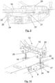
Figure 10 shows a detail view of the first support of the drawbar of the system of the invention, open, showing the upper portion of the support free with respect to the lower portion. -
Figure 11 shows a detail view of the anchoring of the second support to the frame of the trailer, in its free position, i.e., with the upper portion not being fitted in the lower portion, loading/unloading position. -
Figure 12 shows a detail view of the first support. -
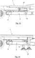
Figure 14 shows a detail view of the trailer-elevating mechanism of the system object of the invention when the road train is in the running position. - Figure 15 shows a detail view of the trailer-elevating mechanism of the system object of the invention when the road train is in the loading/unloading position.
- The different reference numbers shown in the figures correspond to the following elements:
- 1.
- trailer
- 2.
- truck
- 3.
- drawbar
- 4.
- first tubular body
- 5.
- second tubular body
- 6.
- central body
- 7.
- flanges
- 8.
- side housing
- 9.
- first support
- 10.
- drawbar attachment part of the first support
- 11.
- trailer attachment part of the first support
- 12.
- second support
- 13.
- drawbar attachment part of the second support
- 14.
- trailer attachment part of the second support
- 15.
- lug
- 16.
- lower plate
- 17.
- upper plate
- 18.
- opening
- 19.
- main beam
- 20.
- side flat
- 21.
- support element
- 22.
- protrusion
- 23.
- rotation shaft
- 24.
- pin
- 25.
- housing of the protrusion
- 26.
- trailer-elevating mechanism
- 27.
- telescopic supports
- 28.
- attachment means between the drawbar attachment part and the trailer attachment part of the second support
- The system for connecting a trailer (1) and a truck (2) object of the invention comprises a drawbar (3) for connecting the truck (2) and the trailer (1), said drawbar (3) comprising a first tubular body (4) and a second tubular body (5) housed inside the first tubular body (4), such that the second tubular body (5) has ability to move linearly relative to the first tubular body (4), i.e., the drawbar (3) has a telescopic configuration.
- In the preferred embodiment of the invention, the first tubular body (4) comprises four flat parts identical to each other in pairs, which parts are connected forming a box beam, comprising:
- a central housing (6) having a complementary section relative to the second tubular body (5), which is housed inside the first tubular body (4),
- two protrusions (7) on each side of the central housing (6), such that between two protrusions a side housing (8) is configured on each side of the central housing (6).
- For attaching the drawbar (3) to the trailer (1), the system object of the invention comprises:
- a first support (9) comprising a drawbar attachment part (10) and a trailer attachment part (11), such that between the drawbar attachment part (10) and the trailer attachment part (11) the first support (9) comprises a rotation shaft (23) around which the drawbar (3) has the ability to rotate, and
- a second support (12) comprising a drawbar attachment part (13) and a trailer attachment part (14), and attachment means (28) between the drawbar attachment part (13) and the trailer attachment part (14), such that by connecting the drawbar attachment part (13) and the trailer attachment part (14), the drawbar (3) is connected to the trailer (1) by the two supports (9, 12) and the drawbar (3) is positioned parallel with the running plane of the truck (2) and trailer (1) assembly.
- The attachment of the drawbar (3) to the truck (2) is performed by attachment means known in the state of the art.
- In the preferred embodiment of the second support (12), the drawbar attachment part (13) comprises two lugs (15) connected by a lower plate (16) and an upper plate (17) in each side housing (8) of the first tubular body (4), such that each upper plate (17) comprises an opening (18). Likewise, the trailer attachment part (14) comprises a main beam (19) with two side flats (20) and a support element (21) connected to the side flats (20) such that the support element (21) has a frustoconical-shaped protrusion (22) configured for being housed in the opening (18) of the upper plate (17).
- In the preferred embodiment of the invention, the attachment means (28) between the drawbar attachment part (13) and the trailer attachment part (14) of the second support (12) comprise a pin (24) which is introduced in a housing (25) of the frustoconical-shaped protrusion (22) of the support element (21) of the trailer attachment part (14) and abuts with the lower plate (16) of the drawbar attachment part (13), such that the frustoconical-shaped protrusion (22) is housed between the lower plate (16) and the upper plate (17) with the support element (21) against the upper plate (17) and the pin (24) attaching the trailer attachment part (14) to the drawbar attachment part (13).
- In another embodiment of the invention, the attachment means (28) between the drawbar attachment part (13) and the trailer attachment part (14) of the second support (12) comprise pneumatic attachment means which act similarly to the pin (24).
- The system object of the invention also comprises a trailer-elevating mechanism (26) configured for elevating the height of the trailer (1) with respect to the ground, such that the floor of the trailer (1) and the floor of the truck (2) are flush with one another.
- In the preferred embodiment of the invention, the trailer-elevating mechanism (26) comprises telescopic supports (27) with the ability to rotate with respect to the connection with the trailer (1).
- The telescopic supports (27) of the trailer-elevating mechanism (26) of the system object of the invention are to be chosen from pneumatic, hydraulic, mechanical, and a combination thereof.
- Therefore, the system for connecting a truck and a trailer object of the invention has two positions:
- a truck loading position, in which the drawbar is disconnected from the second support (12), with the trailer-elevating mechanism (26) elevating said trailer (1) and with the second tubular body (5) inside the first tubular body (4), i.e., the trailer (1) is in a position close to the truck (2), with the loading platforms at the same level and therefore facilitating the loading of the truck plus trailer assembly from the rear part thereof with a forklift truck that can go from the trailer to the truck without interruption.
- a travel position, in which the drawbar (3) is attached both to the first support (9) and to the second support (12) and is in a position parallel to the running plane of the truck (2) plus trailer (1) assembly, the trailer-elevating mechanism (26) is switched off, and the second tubular body (5) is in the extended position, i.e., with most of said second tubular body outside of the first tubular body (4).
- In the travel position, since the trailer (1) has been lowered, its upper portion is flush with the upper portion of the truck, but it has additional load height since the loading platform is located thereunder, and the distance between a trailer (1) and a truck (2) is the standard distance between same for safe travel.
Claims (6)
- A system for connecting a trailer (1) with a loading platform and a truck (2) with a loading platform, which comprises a drawbar (3) configured to be attached to the truck (2) and to the trailer (1), characterized in that:- the drawbar (3) comprises a first tubular body (4) and a second tubular body (5) with the ability to move linearly with respect to the first tubular body (4),- to attach the drawbar (3) to the trailer (1), the system comprises:- a first support (9) comprising a drawbar attachment part (10) and a trailer attachment part (11), such that between the drawbar attachment part (10) and the trailer attachment part (11) the first support (9) comprises a rotation shaft (23) for the drawbar (3), and- a second support (12) comprising a drawbar attachment part (13) and a trailer attachment part (14), and attachment means (28) between the drawbar attachment part (13) and the trailer attachment part (14),- the system further comprises a trailer-elevating mechanism (26) configured for elevating the height of the trailer (1) with respect to the ground,such that when the drawbar attachment part (13) and the trailer attachment part (14) of the second support (12) are not connected and the elevating mechanism is switched on, the system levels the height of the loading platforms of the truck and the trailer (1), and such that when the drawbar attachment part (13) and the trailer attachment part (14) of the second support (12) are connected, the drawbar (3) is connected to the trailer (1) in a rigid manner, and the trailer-elevating mechanism (26) does not act, the system for connecting provides a connection between the trailer (1) and the truck under safe conditions for travel.
- The system for connecting a trailer (1) and a truck (2) according to claim 1, characterized in that:- the first tubular body (4) comprises four flat parts identical to each other in pairs, which are connected configuring a box beam comprising a central housing (6) having a complementary section relative to the second tubular body (5) and two protrusions (7) on each side of the central housing (6),- in the second support (12):such that the support element (21) comprises a frustoconical-shaped protrusion (22) configured for being housed in the opening (18) of the upper plate (17).- the drawbar attachment part (10) comprises two lugs (15) connected by a lower plate (16) and an upper plate (17) in each side housing (8) of the first tubular body (4), such that each upper plate (17) comprises an opening (18);- the trailer attachment part (11) comprises a main beam (19) with two side flats (20) and a support element (21) connected to the side flats (20),
- The system for connecting a trailer (1) and a truck (2) according to claim 2, characterized in that the attachment means (28) between the drawbar attachment part (13) and the trailer attachment part (14) of the second support (12) comprise a pin (24) configured for being introduced in a housing (25) of the frustoconical-shaped protrusion (22) of the support element (21) of the trailer attachment part (14) and abutting with the lower plate (16) of the drawbar attachment part (13), such that with the frustoconical-shaped protrusion (22) housed between the lower plate (16) and the upper plate (17), the pin (24) attaches the trailer attachment part (14) to the drawbar attachment part (13).
- The system for connecting a trailer (1) and a truck (2) according to claim 2, characterized in that the attachment means (28) between the drawbar attachment part (13) and the trailer attachment part (14) of the second support (12) comprise pneumatic attachment means.
- The system for connecting a trailer (1) and a truck (2) according to any of claims 1 to 4, characterized in that the trailer-elevating mechanism (26) comprises telescopic supports (27) with the ability to rotate with respect to the trailer (1).
- The system for connecting a trailer (1) and a truck (2) according to claim 5, characterized in that the telescopic supports (27) are to be chosen from pneumatic, hydraulic, mechanical, and a combination thereof.
Applications Claiming Priority (2)
| Application Number | Priority Date | Filing Date | Title |
|---|---|---|---|
| ES201930358A ES2788685B2 (en) | 2019-04-22 | 2019-04-22 | JOINT SYSTEM BETWEEN TRAILER AND TRUCK |
| PCT/ES2020/070251 WO2020216974A1 (en) | 2019-04-22 | 2020-04-21 | System for connecting a trailer and a truck |
Publications (4)
| Publication Number | Publication Date |
|---|---|
| EP3960508A1 true EP3960508A1 (en) | 2022-03-02 |
| EP3960508A4 EP3960508A4 (en) | 2022-12-21 |
| EP3960508C0 EP3960508C0 (en) | 2025-04-02 |
| EP3960508B1 EP3960508B1 (en) | 2025-04-02 |
Family
ID=72843531
Family Applications (1)
| Application Number | Title | Priority Date | Filing Date |
|---|---|---|---|
| EP20795332.4A Active EP3960508B1 (en) | 2019-04-22 | 2020-04-21 | System for connecting a trailer and a truck |
Country Status (3)
| Country | Link |
|---|---|
| EP (1) | EP3960508B1 (en) |
| ES (1) | ES2788685B2 (en) |
| WO (1) | WO2020216974A1 (en) |
Family Cites Families (8)
| Publication number | Priority date | Publication date | Assignee | Title |
|---|---|---|---|---|
| US1894320A (en) * | 1931-01-08 | 1933-01-17 | Muchenberger-Wittlin Karl | Single axle tipping trailer |
| US2628126A (en) * | 1948-03-18 | 1953-02-10 | Trailmobile Inc | Two-wheel dump trailer |
| US4589670A (en) * | 1983-06-10 | 1986-05-20 | Sweetin Willard L | Convertible truck/trailer assembly and method |
| FR2636011A1 (en) | 1988-09-06 | 1990-03-09 | Trouillet Carrosserie | Device for hitching between a trailer and a towing vehicle in particular |
| DE4301055A1 (en) * | 1993-01-16 | 1994-07-21 | Hoffmann Heinz Rainer Dr Ing | Drawbar for loading roller container onto trailer |
| US7004548B1 (en) * | 1999-01-12 | 2006-02-28 | James W. Bride | Transfer trailer systems and methods for dump trucks |
| DE10065161A1 (en) * | 2000-12-23 | 2002-07-04 | Deere & Co | Trailer hitch for a work vehicle |
| US20120013093A1 (en) * | 2007-04-17 | 2012-01-19 | A Noy Development Ii, Llc | Modular and collapsible storage and/or transport container apparatus and method and utility trailer system |
-
2019
- 2019-04-22 ES ES201930358A patent/ES2788685B2/en active Active
-
2020
- 2020-04-21 WO PCT/ES2020/070251 patent/WO2020216974A1/en not_active Ceased
- 2020-04-21 EP EP20795332.4A patent/EP3960508B1/en active Active
Also Published As
| Publication number | Publication date |
|---|---|
| EP3960508C0 (en) | 2025-04-02 |
| WO2020216974A1 (en) | 2020-10-29 |
| ES2788685A1 (en) | 2020-10-22 |
| EP3960508B1 (en) | 2025-04-02 |
| ES2788685B2 (en) | 2021-10-05 |
| EP3960508A4 (en) | 2022-12-21 |
Similar Documents
| Publication | Publication Date | Title |
|---|---|---|
| US5489111A (en) | Hidden trailer hitch | |
| US20100213427A1 (en) | Adjustable jack mount | |
| US11007836B2 (en) | Trailer with height-adjusting axle assembly | |
| CN101855106B (en) | Heavy-duty transport modular vehicles especially for ports | |
| JP2007537089A (en) | Plug-in connection | |
| EP1706288A2 (en) | Improved wheel-lift assembly for wreckers | |
| US10676010B2 (en) | Outer guard for transport refrigeration systems | |
| US9511638B2 (en) | Transport hitch system and method | |
| US3253840A (en) | Pneumatic lift system for a tractortrailer hitch | |
| US20170106926A1 (en) | Modular extension tube | |
| EP3960508B1 (en) | System for connecting a trailer and a truck | |
| CN113056410A (en) | Driverless transport vehicle and method for moving a fifth wheel by means of a driverless transport vehicle | |
| US20080003088A1 (en) | Adjustable Schnable | |
| CN217100232U (en) | Logistics vehicle | |
| AU748381B2 (en) | Vehicle with loading boxes for receiving loads | |
| WO2024205541A1 (en) | Mechanical (support) leg mounted on loading ramps | |
| US8075013B2 (en) | Mounting apparatus | |
| EP2873558B1 (en) | Semi-trailer for transporting goods | |
| US7207587B1 (en) | Remote controlled hydraulic gooseneck for tractor trailers | |
| US20230264764A1 (en) | Lifting System for a Semitrailer of an Articulated Lorry, Logistics Depot for a Lorry Fleet, as Well as a Logistics System | |
| EP2139720B1 (en) | Vehicle structure for transporting vehicles and goods | |
| US12195111B2 (en) | Robotized tractor unit | |
| TR201507203A3 (en) | Level adapter | |
| US20190009703A1 (en) | System and method of transporting | |
| EP2669147A1 (en) | An extendable trailer and a combination comprising the trailer for transporting containers of different sizes |
Legal Events
| Date | Code | Title | Description |
|---|---|---|---|
| STAA | Information on the status of an ep patent application or granted ep patent |
Free format text: STATUS: THE INTERNATIONAL PUBLICATION HAS BEEN MADE |
|
| PUAI | Public reference made under article 153(3) epc to a published international application that has entered the european phase |
Free format text: ORIGINAL CODE: 0009012 |
|
| STAA | Information on the status of an ep patent application or granted ep patent |
Free format text: STATUS: REQUEST FOR EXAMINATION WAS MADE |
|
| 17P | Request for examination filed |
Effective date: 20211119 |
|
| AK | Designated contracting states |
Kind code of ref document: A1 Designated state(s): AL AT BE BG CH CY CZ DE DK EE ES FI FR GB GR HR HU IE IS IT LI LT LU LV MC MK MT NL NO PL PT RO RS SE SI SK SM TR |
|
| DAV | Request for validation of the european patent (deleted) | ||
| DAX | Request for extension of the european patent (deleted) | ||
| A4 | Supplementary search report drawn up and despatched |
Effective date: 20221121 |
|
| RIC1 | Information provided on ipc code assigned before grant |
Ipc: B60D 1/66 20060101ALI20221115BHEP Ipc: B60D 1/145 20060101ALI20221115BHEP Ipc: B60D 1/46 20060101ALI20221115BHEP Ipc: B60D 1/155 20060101AFI20221115BHEP |
|
| GRAP | Despatch of communication of intention to grant a patent |
Free format text: ORIGINAL CODE: EPIDOSNIGR1 |
|
| STAA | Information on the status of an ep patent application or granted ep patent |
Free format text: STATUS: GRANT OF PATENT IS INTENDED |
|
| INTG | Intention to grant announced |
Effective date: 20240522 |
|
| GRAJ | Information related to disapproval of communication of intention to grant by the applicant or resumption of examination proceedings by the epo deleted |
Free format text: ORIGINAL CODE: EPIDOSDIGR1 |
|
| STAA | Information on the status of an ep patent application or granted ep patent |
Free format text: STATUS: REQUEST FOR EXAMINATION WAS MADE |
|
| GRAP | Despatch of communication of intention to grant a patent |
Free format text: ORIGINAL CODE: EPIDOSNIGR1 |
|
| STAA | Information on the status of an ep patent application or granted ep patent |
Free format text: STATUS: GRANT OF PATENT IS INTENDED |
|
| INTC | Intention to grant announced (deleted) | ||
| INTG | Intention to grant announced |
Effective date: 20241023 |
|
| GRAS | Grant fee paid |
Free format text: ORIGINAL CODE: EPIDOSNIGR3 |
|
| GRAA | (expected) grant |
Free format text: ORIGINAL CODE: 0009210 |
|
| STAA | Information on the status of an ep patent application or granted ep patent |
Free format text: STATUS: THE PATENT HAS BEEN GRANTED |
|
| AK | Designated contracting states |
Kind code of ref document: B1 Designated state(s): AL AT BE BG CH CY CZ DE DK EE ES FI FR GB GR HR HU IE IS IT LI LT LU LV MC MK MT NL NO PL PT RO RS SE SI SK SM TR |
|
| REG | Reference to a national code |
Ref country code: GB Ref legal event code: FG4D |
|
| REG | Reference to a national code |
Ref country code: CH Ref legal event code: EP |
|
| REG | Reference to a national code |
Ref country code: DE Ref legal event code: R096 Ref document number: 602020048806 Country of ref document: DE |
|
| REG | Reference to a national code |
Ref country code: IE Ref legal event code: FG4D |
|
| U01 | Request for unitary effect filed |
Effective date: 20250430 |
|
| U07 | Unitary effect registered |
Designated state(s): AT BE BG DE DK EE FI FR IT LT LU LV MT NL PT RO SE SI Effective date: 20250512 |
|
| U20 | Renewal fee for the european patent with unitary effect paid |
Year of fee payment: 6 Effective date: 20250527 |
|
| PG25 | Lapsed in a contracting state [announced via postgrant information from national office to epo] |
Ref country code: ES Free format text: LAPSE BECAUSE OF FAILURE TO SUBMIT A TRANSLATION OF THE DESCRIPTION OR TO PAY THE FEE WITHIN THE PRESCRIBED TIME-LIMIT Effective date: 20250402 |
|
| PG25 | Lapsed in a contracting state [announced via postgrant information from national office to epo] |
Ref country code: NO Free format text: LAPSE BECAUSE OF FAILURE TO SUBMIT A TRANSLATION OF THE DESCRIPTION OR TO PAY THE FEE WITHIN THE PRESCRIBED TIME-LIMIT Effective date: 20250702 |
|
| PG25 | Lapsed in a contracting state [announced via postgrant information from national office to epo] |
Ref country code: PL Free format text: LAPSE BECAUSE OF FAILURE TO SUBMIT A TRANSLATION OF THE DESCRIPTION OR TO PAY THE FEE WITHIN THE PRESCRIBED TIME-LIMIT Effective date: 20250402 |
|
| PG25 | Lapsed in a contracting state [announced via postgrant information from national office to epo] |
Ref country code: HR Free format text: LAPSE BECAUSE OF FAILURE TO SUBMIT A TRANSLATION OF THE DESCRIPTION OR TO PAY THE FEE WITHIN THE PRESCRIBED TIME-LIMIT Effective date: 20250402 |
|
| PG25 | Lapsed in a contracting state [announced via postgrant information from national office to epo] |
Ref country code: RS Free format text: LAPSE BECAUSE OF FAILURE TO SUBMIT A TRANSLATION OF THE DESCRIPTION OR TO PAY THE FEE WITHIN THE PRESCRIBED TIME-LIMIT Effective date: 20250702 |
|
| PG25 | Lapsed in a contracting state [announced via postgrant information from national office to epo] |
Ref country code: IS Free format text: LAPSE BECAUSE OF FAILURE TO SUBMIT A TRANSLATION OF THE DESCRIPTION OR TO PAY THE FEE WITHIN THE PRESCRIBED TIME-LIMIT Effective date: 20250802 |
|
| REG | Reference to a national code |
Ref country code: CH Ref legal event code: H13 Free format text: ST27 STATUS EVENT CODE: U-0-0-H10-H13 (AS PROVIDED BY THE NATIONAL OFFICE) Effective date: 20251125 |
|
| PG25 | Lapsed in a contracting state [announced via postgrant information from national office to epo] |
Ref country code: SM Free format text: LAPSE BECAUSE OF FAILURE TO SUBMIT A TRANSLATION OF THE DESCRIPTION OR TO PAY THE FEE WITHIN THE PRESCRIBED TIME-LIMIT Effective date: 20250402 |
|
| PG25 | Lapsed in a contracting state [announced via postgrant information from national office to epo] |
Ref country code: CH Free format text: LAPSE BECAUSE OF NON-PAYMENT OF DUE FEES Effective date: 20250430 |
|
| PG25 | Lapsed in a contracting state [announced via postgrant information from national office to epo] |
Ref country code: CZ Free format text: LAPSE BECAUSE OF FAILURE TO SUBMIT A TRANSLATION OF THE DESCRIPTION OR TO PAY THE FEE WITHIN THE PRESCRIBED TIME-LIMIT Effective date: 20250402 |
|
| PG25 | Lapsed in a contracting state [announced via postgrant information from national office to epo] |
Ref country code: SK Free format text: LAPSE BECAUSE OF FAILURE TO SUBMIT A TRANSLATION OF THE DESCRIPTION OR TO PAY THE FEE WITHIN THE PRESCRIBED TIME-LIMIT Effective date: 20250402 |
|
| PG25 | Lapsed in a contracting state [announced via postgrant information from national office to epo] |
Ref country code: MC Free format text: LAPSE BECAUSE OF FAILURE TO SUBMIT A TRANSLATION OF THE DESCRIPTION OR TO PAY THE FEE WITHIN THE PRESCRIBED TIME-LIMIT Effective date: 20250402 |
|
| PLBE | No opposition filed within time limit |
Free format text: ORIGINAL CODE: 0009261 |
|
| STAA | Information on the status of an ep patent application or granted ep patent |
Free format text: STATUS: NO OPPOSITION FILED WITHIN TIME LIMIT |
|
| REG | Reference to a national code |
Ref country code: CH Ref legal event code: L10 Free format text: ST27 STATUS EVENT CODE: U-0-0-L10-L00 (AS PROVIDED BY THE NATIONAL OFFICE) Effective date: 20260211 |
|
| 26N | No opposition filed |
Effective date: 20260105 |
|
| GBPC | Gb: european patent ceased through non-payment of renewal fee |
Effective date: 20250702 |
|
| PG25 | Lapsed in a contracting state [announced via postgrant information from national office to epo] |
Ref country code: GB Free format text: LAPSE BECAUSE OF NON-PAYMENT OF DUE FEES Effective date: 20250702 |
|
| PG25 | Lapsed in a contracting state [announced via postgrant information from national office to epo] |
Ref country code: IE Free format text: LAPSE BECAUSE OF NON-PAYMENT OF DUE FEES Effective date: 20250421 |