EP3960346A1 - Milling tool and workpiece machining method?flight - Google Patents
Milling tool and workpiece machining method?flight Download PDFInfo
- Publication number
- EP3960346A1 EP3960346A1 EP20795554.3A EP20795554A EP3960346A1 EP 3960346 A1 EP3960346 A1 EP 3960346A1 EP 20795554 A EP20795554 A EP 20795554A EP 3960346 A1 EP3960346 A1 EP 3960346A1
- Authority
- EP
- European Patent Office
- Prior art keywords
- insert
- tip end
- milling tool
- cutting edge
- diameter section
- Prior art date
- Legal status (The legal status is an assumption and is not a legal conclusion. Google has not performed a legal analysis and makes no representation as to the accuracy of the status listed.)
- Pending
Links
Images
















Classifications
-
- B—PERFORMING OPERATIONS; TRANSPORTING
- B23—MACHINE TOOLS; METAL-WORKING NOT OTHERWISE PROVIDED FOR
- B23C—MILLING
- B23C5/00—Milling-cutters
- B23C5/02—Milling-cutters characterised by the shape of the cutter
- B23C5/10—Shank-type cutters, i.e. with an integral shaft
- B23C5/1081—Shank-type cutters, i.e. with an integral shaft with permanently fixed cutting inserts
-
- B—PERFORMING OPERATIONS; TRANSPORTING
- B23—MACHINE TOOLS; METAL-WORKING NOT OTHERWISE PROVIDED FOR
- B23C—MILLING
- B23C5/00—Milling-cutters
- B23C5/02—Milling-cutters characterised by the shape of the cutter
- B23C5/10—Shank-type cutters, i.e. with an integral shaft
- B23C5/109—Shank-type cutters, i.e. with an integral shaft with removable cutting inserts
-
- B—PERFORMING OPERATIONS; TRANSPORTING
- B23—MACHINE TOOLS; METAL-WORKING NOT OTHERWISE PROVIDED FOR
- B23C—MILLING
- B23C3/00—Milling particular work; Special milling operations; Machines therefor
- B23C3/10—Relieving by milling
-
- B—PERFORMING OPERATIONS; TRANSPORTING
- B23—MACHINE TOOLS; METAL-WORKING NOT OTHERWISE PROVIDED FOR
- B23C—MILLING
- B23C2220/00—Details of milling processes
- B23C2220/04—Milling with the axis of the cutter inclined to the surface being machined
-
- B—PERFORMING OPERATIONS; TRANSPORTING
- B23—MACHINE TOOLS; METAL-WORKING NOT OTHERWISE PROVIDED FOR
- B23C—MILLING
- B23C2240/00—Details of connections of tools or workpieces
- B23C2240/08—Brazed connections
-
- B—PERFORMING OPERATIONS; TRANSPORTING
- B23—MACHINE TOOLS; METAL-WORKING NOT OTHERWISE PROVIDED FOR
- B23C—MILLING
- B23C2265/00—Details of general geometric configurations
- B23C2265/08—Conical
Definitions
- the present invention relates to a milling tool which is capable of machining an undercut section such as a rib having a return flange with high efficiency and high accuracy, and a workpiece machining method.
- Patent Literature 1 describes a T-shaped cutter for forming an undercut in a workpiece side surface.
- the T-shaped cutter has a head which is joined to one end of a shank, a plurality of bottom edge parts which have cutting edges on a distal end side of the head and a plurality of upper edge parts which have cutting edges on a proximal end side are alternately arranged in a peripheral direction, and the cutting edges of the bottom edge parts and the top edge parts are formed integral with the shank and the head.
- the cutter since the bottom edge parts, the upper edge parts, the shank, and the head are integrally formed, the cutter has a high rigidity, and accordingly, undercut machining can be performed with high efficiency.
- the higher the rib height the greater the necessary length of the shank, and there is a problem that a large lateral force (bending stress) acts on the shank, deforming the shank, which reduces machining speed and machining accuracy.
- the present invention aims to solve such problems of the prior art and to provide a milling tool and a workpiece machining method with which an undercut section such as a rib having a return flange can be machined high efficiency and high accuracy.
- a milling tool comprising a shank section and a head which is provided on a tip end side of the shank section and which has a cutting edge
- the head has an expanding diameter section which gradually increases in diameter from a base end portion adjoining the shank section in a tip end direction, and a contracting diameter section which gradually decreases in diameter from a maximum diameter section in the tip end direction
- the milling tool comprises at least one cutting edge provided on the expanding diameter section and at least one cutting edge provided the contracting diameter section, and at least one tip end cutting edge which extends from the contracting diameter section to a center axis of the milling tool in a tip end section of the head.
- a workpiece machining method for undercutting inner portions of a rib and a return flange connected thereto, of a workpiece affixed to a table of a machine tool, the method comprising the steps of attaching the milling tool according to claim 1 to a spindle of the machine tool and rotating, machining an inside of the return flange with a cutting edge of the expanding diameter section of the milling tool, and machining a side surface of the rib and a corner between the inside of the return flange and the side surface of the rib with a cutting edge of the contracting diameter section of the milling tool and a tip end cutting edge.
- the head of the milling tool has an expanding diameter section which gradually increases in diameter from a base end portion in a tip end direction, and a contracting diameter section which gradually decreases in diameter from a maximum diameter section in the tip end direction, and cutting edges are provided on the expanding diameter section and the contracting diameter section, by moving the milling tool diagonally toward the undercut section of the workpiece, it is possible to machine the workpiece without interfering with the return flange, whereby the protrusion length of the shank can be shortened.
- the undercut section can be machined efficiently, with high precision and high quality under high machining conditions.
- the tip end cutting edge extending to the center axis of the milling tool enables machining of corners between the inside of the return flange and the side surface of the rib with one tool, reducing the machining time of the workpiece.
- the at least one tip end cutting edge extends from the contracting diameter section to the center axis of the milling tool in the tip end section of the head, corner machining between the bottom wall and the rib and corner machining between the rib and the return flange can be performed at the same time as flat machining, such as the bottom wall, the rib, and the return flange, whereby the undercut section can be machined more efficiently.
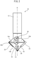
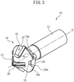
- a milling tool 10 according to a first embodiment of the milling tool of the present invention comprises a cylindrical shank 12 and a head 14 which is integrally formed on the tip end of the shank 12.
- the head 14 has a substantially frustoconical expanding diameter section 14a which increases in diameter from a base end side adjoining the shank 12 in the tip end direction, and a substantially frustoconical contracting diameter section 14b which decreases in diameter from the expanding diameter section 14a in the tip end direction, and the head 14 is formed in a substantially two-sided conical shape.
- a transition section 14c as a maximum diameter section, in which the diameter is maximum, is formed between the expanding diameter section 14a and the contracting diameter section 14b.
- the head 14 has upper grooves 16 formed in the expanding diameter section 14a, lower grooves 18 formed in the contracting diameter section 14b, and a tip end groove 13 for attachment of a tip end insert 30.
- the upper grooves 16 and lower grooves 18 are alternately arranged at equal angles about the central axis O of the head 14.
- the head 14 has two upper grooves 16 and two lower grooves 18. Note that though the upper grooves 16 and lower grooves 18 are arranged at equal angles in the present embodiment, they may be arranged at non-equal angles in order to prevent chatter.
- an upper seat (not illustrated) for attachment of an upper insert 20 is formed in each upper groove 16, and a lower seat (not illustrated) for attachment of a lower insert 22 is formed in each lower groove 18.
- the number of upper inserts 20 and lower inserts 22 is not limited to two in the present invention, and it is sufficient that at least one upper insert 20 and at least one lower insert 22 be arranged.
- each of the expanding diameter section 14a and the contracting diameter section 14b comprise at least one upper groove 16 or lower groove 18.
- the upper seat is formed such that a linear first cutting edge 20c ( FIGS. 6 to 10 ) of the upper insert 20 attached to the upper seat extends diagonally in the direction of rotation of the milling tool 10 gradually approaching the transition section 14c.
- the lower seat is formed so that a linear first cutting edge 22c ( FIG. 11 ) of the lower insert 22 attached to the lower seat extends diagonally in the direction of rotation of the milling tool 10 gradually approaching the transition section 14c.
- a coolant passage for supplying coolant to a machining region can be formed in the milling tool 10.
- the coolant passage can have an inlet passage 24 which penetrates the shank 12 along the central axis O of the milling tool 10, upper radial passages 26a which penetrate the head 14 in the radial direction from the inlet passage 24 and which open into the respective upper grooves 16, and lower radial passages 26b which open into the respective lower grooves 18.
- each upper insert 20 has an upper end section 20a and a lower end section 20b.
- the upper insert 20 is attached to the upper seat so that the lower end section 20b is arranged in the vicinity of the transition section 14c.
- the upper insert 20, when attached to the upper seat, has a rake face 20e which is arranged on the side opposite the upper seat and a first flank face 20d which faces the radially outer side.
- an upper surface 20k is arranged so as to face the shank 12, a rear surface 20f on the side opposite the rake face 20e and a side surface 20g on the side opposite the first flank face 20d adjoin the head 14, and the upper insert 20 is positioned relative to the head 14 by these two surfaces.
- the first cutting edge 20c which extends substantially linearly from the upper surface 20k to a lower surface 20h, is formed by the rake face 20e and the first flank face 20d. Furthermore, the lower surface 20h is upwardly inclined from the rake face 20e side to the rear surface 20f side, and forms a second flank face of the upper insert 20, and a second cutting edge 20j which extends substantially linearly along the lower edge of the upper insert 20 is formed by the rake face 20e and the second flank face 20h.
- the lower insert 22 is formed in substantially the same manner as the upper insert 20, and has an upper end section 22a and a lower end section 22b.
- the lower insert 22 is attached to the lower seat so that the upper end section 22a is arranged in the vicinity of the transition section 14c.
- the lower insert 22 when attached to the lower seat, has a rake face (not illustrated) which is arranged on the side opposite the lower seat, and a first flank face 22d which faces the radially outer side.
- a lower surface 22k faces the tip end direction of the milling tool 10
- a rear surface 22f on the side opposite the rake face and a side surface 22g on the side opposite the first flank face 22d adjoin the head 14, and the lower insert 22 is positioned relative to the head 14 by these two surfaces.
- a first cutting edge 22c which extends substantially linearly from the upper surface 22h to the lower surface 22k, is formed by the rake face and the first flank face 22d. Furthermore, the upper surface 22h is downwardly inclined from the rake face side to the rear surface 22f side, and forms a second flank face of the lower insert 22, and a second cutting edge 22j which extends substantially linearly along the upper edge of the lower insert 22 is formed by the rake face and the second flank face 22h.
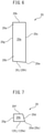
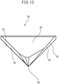
- the tip end insert 30 is formed in a substantially triangular plate shape having a vertex 38 in a plan view (the view from the side surface of the milling tool 10 in FIG. 1 ), as illustrated in FIG. 13 .
- the tip end insert 30 rotates in the direction of arrow 40 centered on the vertex 38.
- the tip end insert 30 has two cutting edges 32 which linearly extend from the vertex 38 along two edges of the triangular shape described above.
- the two cutting edges 32 are arranged on substantially the same straight line when the tip end insert 30 is viewed (in a front view) from the tip end side (the vertex 38 side).
- the cutting edges 32 are formed by the intersections between the rake faces 36 and the flank faces 34.
- one of the two rake faces 36 (the rake face on the right side in FIG. 12 ) is arranged on the upper side of the cutting edge 32 formed by the rake face, and the other rake face 36 (the rake face on the left side in FIG. 12 ) is arranged on the lower side of the cutting edge 32 formed by the rake face.
- the two rake faces 36 are formed so as to face in the same direction relative to the direction of rotation of the milling tool 10.
- one of the two flank faces 34 (the flank face on the right side in FIG. 12 ) is arranged on the lower side of the cutting edge 32 formed by the flank face
- the other flank face 34 (the flank face on the left side in FIG. 12 ) is arranged on the upper side of the cutting edge 32 formed by the flank face.
- the upper insert 20 and the lower insert 22 are attached to the upper seat and the lower seat respectively so that the respective first cutting edges 20c, 22c are aligned with the central axis O of the milling tool 10 in a side surface view.
- the upper inserts 20 are attached to the upper seats so that the first cutting edges 20c of all upper inserts 20 rotate along one conical surface when the milling tool 10 rotates about the central axis O.
- the lower inserts 22 are attached to the lower seats so that the first cutting edges of all lower inserts 22 rotate along one conical surface when the milling tool 10 rotates about the central axis O.
- the upper inserts 20 and the lower inserts 22 are attached to the upper seats and the lower seats respectively so that the intersections 20m, 22m of the first and second cutting edges 20c, 20j; 22c, 22j are arranged on the same circumference centered on the central axis O of the milling tool 10.
- first cutting edges 20c, 22c of the upper insert 20 and the lower insert 22 may not be aligned with the central axis O of the milling tool 10 in a side surface view.
- the upper insert 20 and the lower insert 22 may be attached to the upper seat and the lower seat such that, in a side surface view, the first cutting edge 20c of the upper insert 20 is inclined relative to the direction of rotation of the milling tool 10 so as to extend diagonally rearwardly from the intersection 20m, and the first cutting edge 22c of the lower insert 22 is inclined relative to the direction of rotation of the milling tool 10 so as to extend diagonally rearwardly from the intersection 22m.
- the upper insert 20 and the lower insert 22 may be attached so as to be alternatingly inclined relative to each other.
- the first cutting edge 20c of the upper insert 20 may be inclined relative to the direction of rotation of the milling tool 10 so as to extend diagonally forward from the intersection 20m
- the first cutting edge 22c of the lower insert 22 may be inclined relative to the direction of rotation of the milling tool 10 so as to extend diagonally forwardly from the intersection 22m
- the upper insert 20 and the lower insert 22 may be attached to the upper seat and the lower seat, respectively.
- the upper insert 20 and the lower insert 22 may be attached so as to be alternatingly inclined relative to each other.
- the tip end insert 30 is attached in the tip end groove 13 formed in the tip end section of the head 14 so that the vertex 38 is arranged on the central axis O of the milling tool 10. Furthermore, the cutting edges 32 of the tip end insert 30 are arranged so as to be aligned with a straight line connecting the intersections 20m between the first and second cutting edges 20c, 20j of the two upper inserts 20.
- the two cutting edges 32 of the tip end insert 30 are attached to the tip end groove 13 of the head 14 so as to rotate along a conical surface traced by the first cutting edge of the lower insert 22 and so that the vertex 38 becomes the vertex of this conical surface when the milling tool 10 rotates about the central axis O.
- the angle between the two cutting edges 32 interposing the vertex 38 of the tip end insert 30 is equal to the angle between the two generatrices where the plane containing the central axis of the conical surface (central axis O of the milling tool 10) traced by the first cutting edges 22c of the two lower inserts 22 intersects the conical surface.
- the two conical surfaces traced by the first cutting edges 20c, 22c of the upper insert 20 and the lower insert 22 when the milling tool 10 rotates are symmetrical with respect to the plane defined by the line of intersection between the two conical surfaces, but they may be asymmetric depending on the target machining process and workpiece shape.
- the lines of intersection (the generatrix of each conical surface) of the two conical surfaces described above with the plane containing the central axis O intersect at a predetermined angle. This angle can be any of various values depending on the target machining process.
- the angle formed by the two lines of intersection described above can be, for example, an angle which matches the angle between the rib, which is described later, and the return flange overhanging from the top of the rib, and is preferably an angle which is 90° or less than 90°.
- the first cutting edge 20c of the upper insert 20 is formed so as to be longer than the overhang dimension (width) of the return flange described above.
- shank 12 and the head 14 can be integrally formed using tool steel, and the upper insert 20, the lower insert 22, and the tip end insert 30 can be attached to the upper seat and the lower seat of the head 14 using a suitable joining technique such as brazing.
- the upper insert 20, the lower insert 22, and the tip end insert 30 may be affixed to the head 14 using set screws (not illustrated).
- the upper insert 20, the lower insert 22, and the tip end insert 30 are subjected to grinding, so that the two first cutting edges 20c of the upper insert 20 trace the same conical surface, the two first cutting edges 22c of the lower insert 22 and the two cutting edges 32 of the tip end insert 30 trace the same conical surface, and the intersection 20m of the first and second cutting edges 20c, 20j of the upper insert 20 and the intersection 22m of the first and second cutting edges 22c, 22j of the lower insert 22 trace the same circle.
- FIGS. 16 to 27 An example of a rib machining (undercutting) method using the milling tool 10 will be described below referring to FIGS. 16 to 27 .
- FIGS. 16 to 18 show an example of a workpiece on which rib machining is performed.
- the workpiece 70 serving as the machined product, has a bottom wall 72, a rib 74 forming a thin wall extending perpendicularly from the bottom wall 72, and a return flange 76 protruding from the upper end of the rib 74 substantially in parallel to the bottom wall 72.
- the workpiece 70 is machined from a thick plate composed of a metal material such as an aluminum alloy by attaching the milling tool 10 to the tip end of a spindle (not illustrated) of a machine tool (not illustrated) such as, for example, a 4-axis machining center having three orthogonal linear feed axes and at least one rotational feed axis, and preferably a 5-axis machining center having three orthogonal linear feed axes and two rotational feed axes.
- a machine tool such as, for example, a 4-axis machining center having three orthogonal linear feed axes and at least one rotational feed axis, and preferably a 5-axis machining center having three orthogonal linear feed axes and two rotational feed axes.
- the milling tool 10 is attached to the tip end of the spindle of the machine tool via a tool holder (not illustrated).
- the workpiece 70 is affixed to a table (not illustrated) of the machine tool.
- material is removed from the thick plate, leaving the bottom wall 72, the thin wall serving as the rib 74, the return flange 76, and the portion to be removed (hereinafter referred to as the removal region) 78 between the return flange 76 and the bottom wall 72 in accordance with the width dimension of the return flange 76, as shown in FIG. 18 , using, for example, a rotary tool such as a square end mill which is capable of cutting with the side surface of the tool ( FIG. 18 ).
- a rotary tool such as a square end mill which is capable of cutting with the side surface of the tool ( FIG. 18 ).
- the milling tool 10 which has been positioned in the Z-axis direction so that a finishing allowance ⁇ 1 with respect to the finished surface of the return flange 76 remains and which has been positioned in the X-axis direction so that the amount cut from the surface of the removal region 78 is ⁇ X1, is fed in the Y-axis direction (the direction orthogonal to the sheet of the drawing), whereby a part of the removal region 78 on the lower side of the return flange 76 is removed by first rough machining ( FIG. 19 ). This first rough machining is performed by all of the cutting edges of the upper inserts 20, the lower inserts 22, and tip end insert 30.
- the milling tool 10 When the milling tool 10 is fed in the Y-axis direction (the direction orthogonal to the sheet of the drawing) over the entire length of the workpiece 70 and the first rough machining is completed, without changing the inclination of the spindle, a pick feed corresponding to the finishing allowance ⁇ 1 is imparted to the spindle in the direction approaching the return flange 76 along the Z axis, and first finishing machining for removing the finishing allowance ⁇ 1 remaining on the lower surface of the return flange 76 of the workpiece 70 is executed while feeding the milling tool 10 in the Y-axis direction ( FIG. 20 ).
- the finishing machining can be performed at a higher spindle rotation speed than the rough machining using the same milling tool 10 without replacing the milling tool 10.
- the first finishing machining is primarily performed by the upper inserts 20.
- the milling tool 10 which has been repositioned in the Z-axis direction so that the finishing allowance ⁇ 1 with respect to the finished surface of the return flange 76 remains and which has been imparted in the X-axis direction with a further cutting amount ⁇ X2, is fed in the Y-axis direction, whereby a further portion of the removal region 78 is removed by second rough machining ( FIG. 21 ).
- the further cutting amount ⁇ X2 is determined so that a finishing allowance ⁇ 2 with respect to the finished surface of the rib 74 remains.
- This second rough machining is performed with the upper insert 20, the lower insert 22, and the tip end insert 30.
- a pick feed corresponding to the finishing allowance ⁇ 1 is imparted to the spindle in the direction approaching the return flange 76 along the Z axis, and second finishing machining for removing the finishing allowance ⁇ 1 remaining on the lower surface of the return flange 76 of the workpiece 70 is executed while feeding the milling tool 10 in the Y-axis direction ( FIG. 22 ).
- the second finishing machining is performed by the upper insert 20.
- a pick feed corresponding to the finishing allowance ⁇ 2 is imparted to the spindle in the direction approaching the rib 74 along the X-axis, and a third finishing machining for removing the finishing allowance ⁇ 2 remaining on the surface of the rib 74 of the workpiece 70 is executed while feeding the milling tool 10 (in the illustrated embodiment, the milling tool 10 is fed to the left) in the Y-axis direction ( FIG. 23 ).
- the third finishing machining is performed by the lower inserts 22 and the tip end insert 30.
- the milling tool 10 is repositioned in the Z-axis direction so that a finishing allowance ⁇ 3 with respect to the finished surface of the bottom wall 72 remains, a cutting amount ⁇ X3 is given in the X-axis direction with respect to the surface of the removal region 78, and the milling tool 10 is fed in the Y-axis direction, whereby third rough machining which further removes the removal region 78 is executed.
- the third rough machining is performed by the lower inserts 22 and the tip end insert 30.
- a further cutting amount ⁇ X4 ( FIG. 24 ) is imparted along the X-axis and the milling tool 10 is fed in the Y-axis direction, thereby fourth rough machining which further removes the removal region 78 is executed.
- the fourth rough machining is performed by the lower inserts 22 and the tip end insert 30 ( FIG. 25 ).
- the cutting amount ⁇ X4 is determined so that a finishing allowance ⁇ 4 with respect to the finished surface of the rib 74 remains.
- a pick feed corresponding to the finishing allowance ⁇ 4 is imparted to the spindle in the direction approaching the rib 74 along the X-axis, and fourth finishing machining for removing the finishing allowance ⁇ 4 remaining on the surface of the rib 74 of the workpiece 70 is executed while feeding the milling tool 10 in the Y-axis direction ( FIG. 26 ).
- the fourth finishing machining is performed by the lower inserts 22 and the tip end insert 30.
- a pick feed corresponding to the finishing allowance ⁇ 3 is imparted to the spindle in the direction approaching the bottom wall 72 along the Z axis, and fifth finishing machining for removing the finishing allowance ⁇ 3 remaining on the surface of the rib 74 of the workpiece 70 is executed while feeding the milling tool 10 in the Y-axis direction ( FIG. 27 ).
- the fifth finishing machining is performed by the lower inserts 22 and the tip end insert 30.
- the portion 74a remaining in the corner between the bottom wall 72 and the rib 74 is removed by the tip end insert 30 of the milling tool 10.
- the workpiece 70 having the bottom wall 72, the rib 74 extending vertically from the bottom wall 72, and the return flange 76 protruding substantially parallel to the bottom wall 72 from the top edge of the rib 74 can be machined from a thick metal plate material such as an aluminum alloy.
- the workpiece 70 can be, for example, a component of an aircraft wing.
- the present embodiment is particularly advantageous for the machining of corners not including the corner R, such as the corner between the rib 74 and the return flange 76, or between the bottom wall 72 and the rib 74.
- the milling tool 10 is mounted on the spindle with a short protrusion length, whereby machining of the rib 74 having the return flange 76 can be performed.
- the tool By shortening the protrusion length, the tool conventionally has high static rigidity against bending and distortion and dynamic rigidity against vibration, whereby it is possible to increase the rotational speed and feed rate of the tool.
- chatter is less likely to occur, whereby machined surface quality is improved.
- the present invention is not limited thereto.
- intersection angle of the first cutting edges of the upper insert 20 and the lower insert 22 be equal to or less than the intersection angle of the finished surfaces of the rib 74 and the return flange 76. Furthermore, it is sufficient that the apex angle of the tip end insert 30 be an angle equal to or less than the intersection angle of the finished surfaces of the bottom wall 72 and the rib 74.
- FIGS. 28 to 40 A second embodiment of the present invention will be described with reference to FIGS. 28 to 40 .
- a milling tool 100 comprises a cylindrical shank 102 and a head 104 integrally formed on the tip end of the shank 102.
- the head 104 has a substantially frustoconical expanding diameter section 104a which increases in diameter from a base end side adjoining the shank 102 in the tip end direction, and a substantially frustoconical contracting diameter section 104b which decreases in diameter from the expanding diameter section 104a in the tip end direction, and the head 104 is formed in a substantially two-sided conical shape.
- a transition section 104c as a maximum diameter section, in which the diameter is maximum, is formed between the expanding diameter section 104a and the contracting diameter section 104b.
- the head 104 has upper grooves 106 formed in the expanding diameter section 104a, lower grooves 108 formed in the contracting diameter section 104b, and a tip end groove 103 for attachment of a tip end insert 50.
- the upper grooves 106 and lower grooves 108 are alternately arranged at equal angles about the central axis O of the head 104.
- the head 104 has two upper grooves 106 and two lower grooves 108. Note that though the upper grooves 106 and lower grooves 108 are arranged at equal angles in the present embodiment, they may be arranged at non-equal angles in order to prevent chatter.
- An upper seat (not illustrated) is formed in each upper groove 106, and a lower seat (not illustrated) is formed in each lower groove 108.
- An upper insert 120 is attached to each upper seat and a lower insert 122 is attached to each lower seat.
- the number of upper inserts 120 and lower inserts 122 is not limited to two in the present invention, and it is sufficient that at least one upper insert 120 and at least one lower insert 122 be arranged.
- each of the expanding diameter section 104a and the contracting diameter section 104b comprise at least one upper groove 106 or lower groove 108.
- a coolant passage for supplying coolant to a machining region can be formed in the milling tool 100.
- the coolant passage can have an inlet passage (not illustrated) which penetrates the shank 102 along the central axis O of the milling tool 100, upper radial passages 126a which penetrate the head 104 in the radial directions from the inlet passage 24 and which open into the respective upper grooves 106, and lower radial passages 126b which open into the respective lower grooves 108.
- each upper insert 120 has an upper end section 120a and a lower end section 120b.
- the upper insert 120 is attached to the upper seat so that the lower end section 120b is arranged in the vicinity of the transition section 104c.
- the upper insert 120 when attached to the upper seat, has a flank face 120d which is arranged on the side opposite the upper seat.
- an upper surface 120k is arranged so as to face the shank 102, a rear surface 120f on the side opposite the rake face 120e and a side surface 120g on the side opposite the flank face 120d adjoin the head 104, and the upper insert 120 is positioned relative to the head 104 by these two surfaces.
- a first cutting edge 120c which extends substantially linearly from the upper end section 120a, and an arcuate second cutting edge 120j provided adjacent to the lower end section 120b and connected to the first cutting edge 120c are formed by the rake face 120e and the flank face 120d.
- the lower insert 122 is formed in substantially the same manner.
- the upper inserts 120 are attached to the upper seats so that the first cutting edges 120c of all upper inserts 120 rotate along one conical surface when the milling tool 100 rotates about the central axis O.
- the lower inserts 122 are attached to the lower seats so that the first cutting edges 122c of all lower inserts 122 rotate along one conical surface when the milling tool 100 rotates about the central axis O.
- the tip end insert 50 is formed in a substantially triangular plate shape having a vertex 62 in a plan view (the side surface view of the milling tool 100 in FIG. 28 ).
- the tip end insert 50 has two cutting edges extending linearly from the vertex 62 along two sides of the triangle.
- the two cutting edges each include a main cutting edge 52a extending substantially linearly, and an arcuate secondary cutting edge 52b provided between the vertex 62 and the main cutting edge 52a in a plan view (the side surface view of the milling tool 100 in FIG. 28 ).
- Each of the two sets of cutting edges 52a and 52b is formed by the line of intersection of the rake face 56 and the flank face 54.
- one of the two rake faces 56 (the rake face on the right side in FIG. 37 ) is arranged on the upper side of the cutting edges 52a, 52b formed by the rake face, and the other rake face 56 (the rake face on the left side in FIG. 37 ) is arranged on the lower side of the cutting edges 52a, 52b formed by the rake face.
- the two rake faces 36 are formed so as to face in the same direction with respect to the direction of rotation of the milling tool 10.
- one of the two flank faces 54 (the flank face on the right side in FIG.
- flank face 54 (the flank face on the left side in FIG. 37 ) is arranged on the upper side of the cutting edges 52a, 52b formed by the flank face.
- the two linear main cutting edges 52a extend parallel to each other and do not intersect at vertex 62.
- Each of the two arcuate secondary cutting edges 52b is formed so as to adjoin the linear main cutting edges 52a.
- the two arcuate secondary cutting edges 52b are formed so as to trace a common sphere in the vicinity of the vertex 62 when the milling tool 100 rotates about the central axis O.
- the two secondary cutting edges 52b are arranged on a common arc.
- the tip end insert 50 has one swarf discharge groove 58 provided adjacent to each of the main cutting edges 52a.
- the tip end insert 50 also has two clearance grooves 60 provided in the vicinity of the vertex 62.
- the two secondary cutting edges 52b are arranged between the two clearance grooves 60.
- the tip end insert 50 is attached in the tip end groove 103 formed in the tip end section of the head 104 so that the vertex 62 is arranged on the central axis O of the milling tool 100. Further, the two main cutting edges 52a of the tip end insert 50 are attached in the tip end groove 103 of the head 104 so as to rotate along the conical surface traced by the first cutting edge 122c of the lower insert 122 when the milling tool 100 rotates about the central axis O.
- the angle between the two main cutting edges 52a interposing the vertex 62 of the tip end insert 50 is equal to the angle between the two generatrices where the plane containing the central axis of the conical surface (central axis O of the milling tool 100) traced by the first cutting edges 122c of the two lower inserts 122 intersects the conical surface.
- the two conical surfaces traced by the first cutting edges 120c, 122c of the upper inserts 120 and the lower inserts 122 when the milling tool 100 rotates are symmetrical with respect to the plane defined by the line of intersection between the two conical surfaces, but they may be asymmetric depending on the target machining process or workpiece shape.
- the lines of intersection (the generatrix of each conical surface) of the two conical surfaces described above with the plane containing the central axis O intersect at a predetermined angle. This angle can be any of various values depending on the target machining process.
- the angle formed by the two lines of intersection described above can be, for example, an angle which matches the angle between the rib, which is described later, and the return flange overhanging from the top of the rib, and is preferably an angle which is 90° or less than 90°.
- the first cutting edge 120c of the upper insert 120 is formed so as to be longer than the overhang dimension (width) of the return flange described above.
- the upper insert 120 and the lower insert 122 are attached to the upper seat and the lower seat so that the second cutting edges 120j, 122j move along a rotating body shape which is a locus when one arc which protrudes in the radial direction of the head 104 rotates about the central axis O of the milling tool 100 when the milling tool 100 rotates about the central axis O.
- This rotating body shape can be inscribed in both of the two conical surfaces traced by the first cutting edges 120c, 122c of the upper insert 120 and the lower insert 122 when the milling tool 100 rotates.
- shank 102 and the head 104 can be integrally formed using tool steel, and the upper inserts 120, the lower inserts 122, and the tip end insert 50 can be attached to the upper seats and the lower seats of the head 104 using a suitable joining technique such as brazing.
- the upper inserts 120, the lower inserts 122, and the tip end insert 50 may be affixed to the head 104 using set screws (not illustrated).
- the upper insert 120, the lower insert 122, and the tip end insert 50 are subjected to grinding, so that the two first cutting edges 120c of the upper insert 20 trace the same conical surface, and the two first cutting edges 122c of the lower insert 122 and the two cutting edges 32 of the tip end insert 30 trace the same conical surface.
- the generatrix of each of the two conical surfaces traced by the first cutting edge 120c of the upper insert 120 and the first cutting edge 122c of the lower insert 122 described above assume an angle which matches the angle between the rib of the workpiece and the return flange protruding from the upper end of the rib, and the rotating body shape traced by the second cutting edges 120j, 122j can be inscribed in both of the two conical surfaces.
- the milling tool 100 can perform machining of a rib having a return flange by the same procedure as the milling tool 10 described with reference to FIGS. 16 to 27 .
- the milling tool 10 is suitable for machining corners not including the corner R, as described above, the milling tool 100 is suitable for machining corners including the corner R, as shown in FIG. 41 .
- the workpiece 80 has a bottom wall 82, a rib 84 forming a thin wall extending vertically from the bottom wall 82, and a return flange 86 protruding from the upper end of the rib 84 to both sides substantially in parallel to the bottom wall 82.
- the corners between the bottom wall 82 and the rib 84 and the corners between the rib 84 and the return flange 86 become corners R.
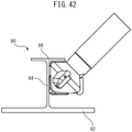
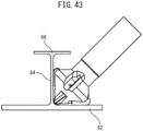
- the corners R between the bottom wall 82 and the rib 84 are machined by the secondary cutting edges 52b of the tip end insert 50, and the corners R between the rib 84 and the return flange 86 are machined by the second cutting edges 120j, 122j of the upper inserts 120 and the lower inserts 122.
- the milling tool 200 according to the third embodiment is configured in substantially the same manner as the milling tool 100 according to the second embodiment, and comprises a cylindrical shank 202 and a head 204 integrally formed on the tip end of the shank 202.
- the head 204 has a substantially frustoconical expanding diameter section 204a which increases in diameter from a base end side adjoining the shank 202 in the tip end direction, and a substantially frustoconical contracting diameter section 204b which decreases in diameter from the expanding diameter section 204a in the tip end direction, and the head 204 is formed in a substantially two-sided conical shape.
- the head 204 has upper grooves 206 formed in the expanding diameter section 204a, lower grooves 208 formed in the contracting diameter section 204b, and a tip end groove 203 for attachment of a tip end insert 230.
- the upper grooves 206 and lower grooves 208 are alternately arranged at equal angles about the central axis O of the head 204.
- the head 204 has two upper grooves 206 and two lower grooves 208.
- the upper grooves 206 and lower grooves 208 are arranged at equal angles about the central axis O of the head 204.
- the head 204 has two upper grooves 206 and two lower grooves 208.
- the upper grooves 206 and lower grooves 208 are arranged at equal angles in the present embodiment, they may be arranged at non-equal angles in order to prevent chatter.
- An upper insert 220 is attached in each upper groove 206, and a lower insert 222 is attached in each lower groove 208.
- the upper inserts 220 and lower inserts 222 are identical to the upper inserts 120 and lower inserts 122 of the second embodiment.
- the tip end insert 230 is formed in a substantially triangular plate shape having a vertex 242.
- the tip end insert 230 has two cutting edges extending linearly from the vertex 242 along two sides of the triangle.
- the two cutting edges each include a first cutting edge 232a extending substantially linearly, and an arcuate second cutting edge 232b provided between the vertex 242 and the first cutting edge 232a in a plan view (the side surface view of the milling tool 200 in FIG. 44 ).
- Each of the two sets of cutting edges 232a and 232b is formed by the line of intersection of a rake face 236 and a flank face 234.
- the tip end insert 230 is affixed to the head 204 with set screws 212.
- the head 204 has a notch 210 in the tip end section thereof. Threaded holes (not illustrated) for threading of the set screws 212 are formed in the notch 210, and the tip end insert 230 has recesses 240 similar to the tip end shape of the set screws 212.
- the present invention is not limited thereto, and at least one upper insert and at least one lower insert may be provided.
- the present invention may be applied to an insert tool or a solid tool with cutting edges in which the respective roles of the main cutting edges of the upper inserts, the secondary cutting edges in the vicinity of the maximum diameter, the main cutting edges of the lower insert, the main cutting edges of the tip end insert, and the tip end cutting edge are split or integrated.
Landscapes
- Engineering & Computer Science (AREA)
- Mechanical Engineering (AREA)
- Milling Processes (AREA)
Abstract
Description
- The present invention relates to a milling tool which is capable of machining an undercut section such as a rib having a return flange with high efficiency and high accuracy, and a workpiece machining method.
-
Patent Literature 1 describes a T-shaped cutter for forming an undercut in a workpiece side surface. The T-shaped cutter has a head which is joined to one end of a shank, a plurality of bottom edge parts which have cutting edges on a distal end side of the head and a plurality of upper edge parts which have cutting edges on a proximal end side are alternately arranged in a peripheral direction, and the cutting edges of the bottom edge parts and the top edge parts are formed integral with the shank and the head. - [PTL 1]
WO 2014/068710 - In the T-shaped cutter of
Patent Literature 1, since the bottom edge parts, the upper edge parts, the shank, and the head are integrally formed, the cutter has a high rigidity, and accordingly, undercut machining can be performed with high efficiency. However, the higher the rib height, the greater the necessary length of the shank, and there is a problem that a large lateral force (bending stress) acts on the shank, deforming the shank, which reduces machining speed and machining accuracy. - The present invention aims to solve such problems of the prior art and to provide a milling tool and a workpiece machining method with which an undercut section such as a rib having a return flange can be machined high efficiency and high accuracy.
- In order to achieve the object described above, according to the present invention, there is provided a milling tool comprising a shank section and a head which is provided on a tip end side of the shank section and which has a cutting edge, wherein the head has an expanding diameter section which gradually increases in diameter from a base end portion adjoining the shank section in a tip end direction, and a contracting diameter section which gradually decreases in diameter from a maximum diameter section in the tip end direction, and the milling tool comprises at least one cutting edge provided on the expanding diameter section and at least one cutting edge provided the contracting diameter section, and at least one tip end cutting edge which extends from the contracting diameter section to a center axis of the milling tool in a tip end section of the head.
- Furthermore, according to the present invention, there is provided a workpiece machining method for undercutting inner portions of a rib and a return flange connected thereto, of a workpiece affixed to a table of a machine tool, the method comprising the steps of attaching the milling tool according to claim 1 to a spindle of the machine tool and rotating, machining an inside of the return flange with a cutting edge of the expanding diameter section of the milling tool, and machining a side surface of the rib and a corner between the inside of the return flange and the side surface of the rib with a cutting edge of the contracting diameter section of the milling tool and a tip end cutting edge.
- According to the present invention, since the head of the milling tool has an expanding diameter section which gradually increases in diameter from a base end portion in a tip end direction, and a contracting diameter section which gradually decreases in diameter from a maximum diameter section in the tip end direction, and cutting edges are provided on the expanding diameter section and the contracting diameter section, by moving the milling tool diagonally toward the undercut section of the workpiece, it is possible to machine the workpiece without interfering with the return flange, whereby the protrusion length of the shank can be shortened. Thus, the undercut section can be machined efficiently, with high precision and high quality under high machining conditions. Furthermore, the tip end cutting edge extending to the center axis of the milling tool enables machining of corners between the inside of the return flange and the side surface of the rib with one tool, reducing the machining time of the workpiece.
- Furthermore, since the at least one tip end cutting edge extends from the contracting diameter section to the center axis of the milling tool in the tip end section of the head, corner machining between the bottom wall and the rib and corner machining between the rib and the return flange can be performed at the same time as flat machining, such as the bottom wall, the rib, and the return flange, whereby the undercut section can be machined more efficiently.
-
-
FIG. 1 is a front view of a milling tool according to a first embodiment of the present invention. -
FIG. 2 is a side view of the milling tool as viewed from a direction differing by 90° fromFIG. 1 -
FIG. 3 is a perspective view of the milling tool ofFIG. 1 . -
FIG. 4 is a bottom view of the milling tool ofFIG. 1 as viewed from the head side. -
FIG. 5 is a plan view of the milling tool ofFIG. 1 as viewed from the shank side. -
FIG. 6 is a front view of an upper insert used in the milling tool ofFIG. 1 . -
FIG. 7 is a bottom view of the upper insert ofFIG. 6 . -
FIG. 8 is a side view of the upper insert ofFIG. 6 . -
FIG. 9 is a rear view of the upper insert ofFIG. 6 . -
FIG. 10 is a perspective view of the upper insert ofFIG. 6 . -
FIG. 11 is a rear view of a lower insert used in the milling tool ofFIG. 1 . -
FIG. 12 is a front view of a tip end insert used in the milling tool ofFIG. 1 . -
FIG. 13 is a perspective view of the tip end insert ofFIG. 12 as viewed from the tip end side. -
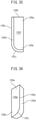
FIG. 14 is a side view of the tip end insert ofFIG. 12 . -
FIG. 15 is a perspective view of the tip end insert ofFIG. 12 as viewed from another angle. -
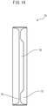
FIG. 16 is a plan view showing an example of a workpiece having a return flange to be machined with the milling tool ofFIG. 1 . -
FIG. 17 is a cross-sectional view of the workpiece ofFIG. 16 . -
FIG. 18 is a schematic diagram detailing a method for machining a rib having a return flange. -
FIG. 19 is a schematic diagram detailing the method for machining the rib having a return flange. -
FIG. 20 is a schematic diagram detailing the method for machining the rib having a return flange. -
FIG. 21 is a schematic diagram detailing the method for machining the rib having a return flange. -
FIG. 22 is a schematic diagram detailing the method for machining the rib having a return flange. -
FIG. 23 is a schematic diagram detailing the method for machining the rib having a return flange. -
FIG. 24 is a schematic diagram detailing the method for machining the rib having a return flange. -
FIG. 25 is a schematic diagram detailing the method for machining the rib having a return flange. -
FIG. 26 is a schematic diagram detailing the method for machining the rib having a return flange. -
FIG. 27 is a schematic diagram detailing the method for machining the rib having a return flange. -
FIG. 28 is a front view of a milling tool according to a second embodiment of the present invention. -
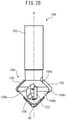
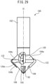
FIG. 29 is a side view of the milling tool as viewed from a direction differing by 90° fromFIG. 28 . -
FIG. 30 is a perspective view of the milling tool ofFIG. 28 . -
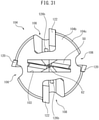
FIG. 31 is a bottom view of the milling tool ofFIG. 28 as viewed from the head side. -
FIG. 32 is a front view of an upper insert used in the milling tool ofFIG. 28 . -
FIG. 33 is a bottom view of the upper insert ofFIG. 32 . -
FIG. 34 is a side view of the upper insert ofFIG. 32 . -
FIG. 35 is a rear view of the upper insert ofFIG. 32 . -
FIG. 36 is a perspective view of the upper insert ofFIG. 32 . -
FIG. 37 is a front view of a tip end insert used in the milling tool ofFIG. 28 . -
FIG. 38 is a perspective view of the tip end insert ofFIG. 37 as viewed from the tip end side. -
FIG. 39 is a side view of the tip end insert ofFIG. 37 . -
FIG. 40 is a perspective view of the tip end insert ofFIG. 37 as viewed from another angle. -
FIG. 41 is an end view showing an example of a workpiece having a return flange machined with the milling tool ofFIG. 28 , which has corners R between the bottom wall and the rib and the rib and the return flange. -
FIG. 42 is a schematic diagram detailing the machining of the corners R of the workpiece ofFIG. 41 with the milling tool according to the second embodiment. -
Fig. 43 is a schematic diagram detailing the machining of the corners R of the workpiece ofFIG. 41 with the milling tool according to the second embodiment. -
FIG. 44 is a front view of a milling tool according to a third embodiment of the present invention. -
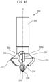
FIG. 45 is a side view of the milling tool as viewed from a direction differing by 90° fromFIG. 44 . -
FIG. 46 is a perspective view of the milling tool ofFIG. 44 . -
FIG. 47 is a perspective view of a tip end insert used in the milling tool ofFIG. 44 . - Preferred embodiments of the present invention will be described below with reference to the attached drawings.
- Referring to
FIGS. 1 to 15 , amilling tool 10 according to a first embodiment of the milling tool of the present invention comprises acylindrical shank 12 and ahead 14 which is integrally formed on the tip end of theshank 12. Thehead 14 has a substantially frustoconical expandingdiameter section 14a which increases in diameter from a base end side adjoining theshank 12 in the tip end direction, and a substantially frustoconicalcontracting diameter section 14b which decreases in diameter from the expandingdiameter section 14a in the tip end direction, and thehead 14 is formed in a substantially two-sided conical shape. Atransition section 14c as a maximum diameter section, in which the diameter is maximum, is formed between the expandingdiameter section 14a and thecontracting diameter section 14b. Thehead 14 hasupper grooves 16 formed in the expandingdiameter section 14a,lower grooves 18 formed in thecontracting diameter section 14b, and atip end groove 13 for attachment of atip end insert 30. - The
upper grooves 16 andlower grooves 18 are alternately arranged at equal angles about the central axis O of thehead 14. In the illustrated embodiment, thehead 14 has twoupper grooves 16 and twolower grooves 18. Note that though theupper grooves 16 andlower grooves 18 are arranged at equal angles in the present embodiment, they may be arranged at non-equal angles in order to prevent chatter. - An upper seat (not illustrated) for attachment of an
upper insert 20 is formed in eachupper groove 16, and a lower seat (not illustrated) for attachment of alower insert 22 is formed in eachlower groove 18. Though twoupper inserts 20 are arranged in the expandingdiameter section 14a and twolower inserts 22 are arranged in thecontracting diameter section 14b in the illustrated embodiment, the number ofupper inserts 20 andlower inserts 22 is not limited to two in the present invention, and it is sufficient that at least oneupper insert 20 and at least onelower insert 22 be arranged. Thus, it is sufficient that each of the expandingdiameter section 14a and thecontracting diameter section 14b comprise at least oneupper groove 16 orlower groove 18. - The upper seat is formed such that a linear
first cutting edge 20c (FIGS. 6 to 10 ) of theupper insert 20 attached to the upper seat extends diagonally in the direction of rotation of themilling tool 10 gradually approaching thetransition section 14c. The lower seat is formed so that a linearfirst cutting edge 22c (FIG. 11 ) of thelower insert 22 attached to the lower seat extends diagonally in the direction of rotation of themilling tool 10 gradually approaching thetransition section 14c. - Further, a coolant passage for supplying coolant to a machining region can be formed in the
milling tool 10. The coolant passage can have aninlet passage 24 which penetrates theshank 12 along the central axis O of themilling tool 10, upperradial passages 26a which penetrate thehead 14 in the radial direction from theinlet passage 24 and which open into the respectiveupper grooves 16, and lowerradial passages 26b which open into the respectivelower grooves 18. - Referring to
FIGS. 6 to 10 , eachupper insert 20 has anupper end section 20a and alower end section 20b. Theupper insert 20 is attached to the upper seat so that thelower end section 20b is arranged in the vicinity of thetransition section 14c. Theupper insert 20, when attached to the upper seat, has arake face 20e which is arranged on the side opposite the upper seat and afirst flank face 20d which faces the radially outer side. In this manner, when theupper insert 20 is attached to thehead 14, anupper surface 20k is arranged so as to face theshank 12, arear surface 20f on the side opposite therake face 20e and aside surface 20g on the side opposite thefirst flank face 20d adjoin thehead 14, and theupper insert 20 is positioned relative to thehead 14 by these two surfaces. - The
first cutting edge 20c, which extends substantially linearly from theupper surface 20k to alower surface 20h, is formed by therake face 20e and thefirst flank face 20d. Furthermore, thelower surface 20h is upwardly inclined from therake face 20e side to therear surface 20f side, and forms a second flank face of theupper insert 20, and asecond cutting edge 20j which extends substantially linearly along the lower edge of theupper insert 20 is formed by therake face 20e and thesecond flank face 20h. - Referring to
FIG. 11 , thelower insert 22 is formed in substantially the same manner as theupper insert 20, and has anupper end section 22a and alower end section 22b. Thelower insert 22 is attached to the lower seat so that theupper end section 22a is arranged in the vicinity of thetransition section 14c. Furthermore, thelower insert 22, when attached to the lower seat, has a rake face (not illustrated) which is arranged on the side opposite the lower seat, and afirst flank face 22d which faces the radially outer side. In this manner, when thelower insert 22 is attached to thehead 14, alower surface 22k faces the tip end direction of themilling tool 10, and arear surface 22f on the side opposite the rake face and aside surface 22g on the side opposite thefirst flank face 22d adjoin thehead 14, and thelower insert 22 is positioned relative to thehead 14 by these two surfaces. - A
first cutting edge 22c, which extends substantially linearly from the upper surface 22h to thelower surface 22k, is formed by the rake face and thefirst flank face 22d. Furthermore, the upper surface 22h is downwardly inclined from the rake face side to therear surface 22f side, and forms a second flank face of thelower insert 22, and asecond cutting edge 22j which extends substantially linearly along the upper edge of thelower insert 22 is formed by the rake face and the second flank face 22h. - The
tip end insert 30 is formed in a substantially triangular plate shape having avertex 38 in a plan view (the view from the side surface of themilling tool 10 inFIG. 1 ), as illustrated inFIG. 13 . Thetip end insert 30 rotates in the direction ofarrow 40 centered on thevertex 38. Thetip end insert 30 has twocutting edges 32 which linearly extend from thevertex 38 along two edges of the triangular shape described above. The twocutting edges 32 are arranged on substantially the same straight line when thetip end insert 30 is viewed (in a front view) from the tip end side (thevertex 38 side). The cutting edges 32 are formed by the intersections between the rake faces 36 and the flank faces 34. When the tip end insert is viewed from the tip end side, one of the two rake faces 36 (the rake face on the right side inFIG. 12 ) is arranged on the upper side of thecutting edge 32 formed by the rake face, and the other rake face 36 (the rake face on the left side inFIG. 12 ) is arranged on the lower side of thecutting edge 32 formed by the rake face. In this manner, the two rake faces 36 are formed so as to face in the same direction relative to the direction of rotation of themilling tool 10. Furthermore, when the tip end insert is viewed from the tip end side, one of the two flank faces 34 (the flank face on the right side inFIG. 12 ) is arranged on the lower side of thecutting edge 32 formed by the flank face, and the other flank face 34 (the flank face on the left side inFIG. 12 ) is arranged on the upper side of thecutting edge 32 formed by the flank face. - In the present embodiment, the
upper insert 20 and thelower insert 22 are attached to the upper seat and the lower seat respectively so that the respectivefirst cutting edges milling tool 10 in a side surface view. Further, theupper inserts 20 are attached to the upper seats so that thefirst cutting edges 20c of allupper inserts 20 rotate along one conical surface when themilling tool 10 rotates about the central axis O. Likewise, thelower inserts 22 are attached to the lower seats so that the first cutting edges of alllower inserts 22 rotate along one conical surface when themilling tool 10 rotates about the central axis O. Furthermore, theupper inserts 20 and thelower inserts 22 are attached to the upper seats and the lower seats respectively so that theintersections second cutting edges milling tool 10. - Note that the
first cutting edges upper insert 20 and thelower insert 22 may not be aligned with the central axis O of themilling tool 10 in a side surface view. For example, theupper insert 20 and thelower insert 22 may be attached to the upper seat and the lower seat such that, in a side surface view, thefirst cutting edge 20c of theupper insert 20 is inclined relative to the direction of rotation of themilling tool 10 so as to extend diagonally rearwardly from theintersection 20m, and thefirst cutting edge 22c of thelower insert 22 is inclined relative to the direction of rotation of themilling tool 10 so as to extend diagonally rearwardly from theintersection 22m. In this case, theupper insert 20 and thelower insert 22 may be attached so as to be alternatingly inclined relative to each other. - Further, in a side surface view of the
milling tool 10, thefirst cutting edge 20c of theupper insert 20 may be inclined relative to the direction of rotation of themilling tool 10 so as to extend diagonally forward from theintersection 20m, thefirst cutting edge 22c of thelower insert 22 may be inclined relative to the direction of rotation of themilling tool 10 so as to extend diagonally forwardly from theintersection 22m, and theupper insert 20 and thelower insert 22 may be attached to the upper seat and the lower seat, respectively. In this case as well, theupper insert 20 and thelower insert 22 may be attached so as to be alternatingly inclined relative to each other. - As shown in
FIG. 4 , thetip end insert 30 is attached in thetip end groove 13 formed in the tip end section of thehead 14 so that thevertex 38 is arranged on the central axis O of themilling tool 10. Furthermore, the cutting edges 32 of thetip end insert 30 are arranged so as to be aligned with a straight line connecting theintersections 20m between the first andsecond cutting edges upper inserts 20. - Further, the two
cutting edges 32 of thetip end insert 30 are attached to thetip end groove 13 of thehead 14 so as to rotate along a conical surface traced by the first cutting edge of thelower insert 22 and so that thevertex 38 becomes the vertex of this conical surface when themilling tool 10 rotates about the central axis O. Specifically, the angle between the twocutting edges 32 interposing thevertex 38 of thetip end insert 30 is equal to the angle between the two generatrices where the plane containing the central axis of the conical surface (central axis O of the milling tool 10) traced by thefirst cutting edges 22c of the twolower inserts 22 intersects the conical surface. - In the illustrated embodiment, the two conical surfaces traced by the
first cutting edges upper insert 20 and thelower insert 22 when themilling tool 10 rotates are symmetrical with respect to the plane defined by the line of intersection between the two conical surfaces, but they may be asymmetric depending on the target machining process and workpiece shape. Furthermore, the lines of intersection (the generatrix of each conical surface) of the two conical surfaces described above with the plane containing the central axis O intersect at a predetermined angle. This angle can be any of various values depending on the target machining process. The angle formed by the two lines of intersection described above can be, for example, an angle which matches the angle between the rib, which is described later, and the return flange overhanging from the top of the rib, and is preferably an angle which is 90° or less than 90°. Furthermore, thefirst cutting edge 20c of theupper insert 20 is formed so as to be longer than the overhang dimension (width) of the return flange described above. - Furthermore, the
shank 12 and thehead 14 can be integrally formed using tool steel, and theupper insert 20, thelower insert 22, and thetip end insert 30 can be attached to the upper seat and the lower seat of thehead 14 using a suitable joining technique such as brazing. Theupper insert 20, thelower insert 22, and thetip end insert 30 may be affixed to thehead 14 using set screws (not illustrated). - After the
upper insert 20, thelower insert 22, and thetip end insert 30 have been attached, theupper insert 20, thelower insert 22, and thetip end insert 30 are subjected to grinding, so that the twofirst cutting edges 20c of theupper insert 20 trace the same conical surface, the twofirst cutting edges 22c of thelower insert 22 and the twocutting edges 32 of thetip end insert 30 trace the same conical surface, and theintersection 20m of the first andsecond cutting edges upper insert 20 and theintersection 22m of the first andsecond cutting edges lower insert 22 trace the same circle. - An example of a rib machining (undercutting) method using the
milling tool 10 will be described below referring toFIGS. 16 to 27 . -
FIGS. 16 to 18 show an example of a workpiece on which rib machining is performed. Theworkpiece 70, serving as the machined product, has abottom wall 72, arib 74 forming a thin wall extending perpendicularly from thebottom wall 72, and areturn flange 76 protruding from the upper end of therib 74 substantially in parallel to thebottom wall 72. Theworkpiece 70 is machined from a thick plate composed of a metal material such as an aluminum alloy by attaching themilling tool 10 to the tip end of a spindle (not illustrated) of a machine tool (not illustrated) such as, for example, a 4-axis machining center having three orthogonal linear feed axes and at least one rotational feed axis, and preferably a 5-axis machining center having three orthogonal linear feed axes and two rotational feed axes. Note that themilling tool 10 is attached to the tip end of the spindle of the machine tool via a tool holder (not illustrated). Furthermore, theworkpiece 70 is affixed to a table (not illustrated) of the machine tool. - First, material is removed from the thick plate, leaving the
bottom wall 72, the thin wall serving as therib 74, thereturn flange 76, and the portion to be removed (hereinafter referred to as the removal region) 78 between thereturn flange 76 and thebottom wall 72 in accordance with the width dimension of thereturn flange 76, as shown inFIG. 18 , using, for example, a rotary tool such as a square end mill which is capable of cutting with the side surface of the tool (FIG. 18 ). - Next, the
milling tool 10, which has been positioned in the Z-axis direction so that a finishing allowance δ1 with respect to the finished surface of thereturn flange 76 remains and which has been positioned in the X-axis direction so that the amount cut from the surface of theremoval region 78 is ΔX1, is fed in the Y-axis direction (the direction orthogonal to the sheet of the drawing), whereby a part of theremoval region 78 on the lower side of thereturn flange 76 is removed by first rough machining (FIG. 19 ). This first rough machining is performed by all of the cutting edges of theupper inserts 20, thelower inserts 22, andtip end insert 30. - When the
milling tool 10 is fed in the Y-axis direction (the direction orthogonal to the sheet of the drawing) over the entire length of theworkpiece 70 and the first rough machining is completed, without changing the inclination of the spindle, a pick feed corresponding to the finishing allowance δ1 is imparted to the spindle in the direction approaching thereturn flange 76 along the Z axis, and first finishing machining for removing the finishing allowance δ1 remaining on the lower surface of thereturn flange 76 of theworkpiece 70 is executed while feeding themilling tool 10 in the Y-axis direction (FIG. 20 ). The finishing machining can be performed at a higher spindle rotation speed than the rough machining using thesame milling tool 10 without replacing themilling tool 10. Furthermore, the first finishing machining is primarily performed by the upper inserts 20. - Next, as shown in
FIG. 21 , themilling tool 10, which has been repositioned in the Z-axis direction so that the finishing allowance δ1 with respect to the finished surface of thereturn flange 76 remains and which has been imparted in the X-axis direction with a further cutting amount ΔX2, is fed in the Y-axis direction, whereby a further portion of theremoval region 78 is removed by second rough machining (FIG. 21 ). At this time, the further cutting amount ΔX2 is determined so that a finishing allowance δ2 with respect to the finished surface of therib 74 remains. This second rough machining is performed with theupper insert 20, thelower insert 22, and thetip end insert 30. - After the second rough machining is complete, without changing the inclination of the spindle, a pick feed corresponding to the finishing allowance δ1 is imparted to the spindle in the direction approaching the
return flange 76 along the Z axis, and second finishing machining for removing the finishing allowance δ1 remaining on the lower surface of thereturn flange 76 of theworkpiece 70 is executed while feeding themilling tool 10 in the Y-axis direction (FIG. 22 ). The second finishing machining is performed by theupper insert 20. - Next, a pick feed corresponding to the finishing allowance δ2 is imparted to the spindle in the direction approaching the
rib 74 along the X-axis, and a third finishing machining for removing the finishing allowance δ2 remaining on the surface of therib 74 of theworkpiece 70 is executed while feeding the milling tool 10 (in the illustrated embodiment, themilling tool 10 is fed to the left) in the Y-axis direction (FIG. 23 ). The third finishing machining is performed by thelower inserts 22 and thetip end insert 30. - Next, as shown in
FIG. 24 , themilling tool 10 is repositioned in the Z-axis direction so that a finishing allowance δ3 with respect to the finished surface of thebottom wall 72 remains, a cutting amount ΔX3 is given in the X-axis direction with respect to the surface of theremoval region 78, and themilling tool 10 is fed in the Y-axis direction, whereby third rough machining which further removes theremoval region 78 is executed. At this time, the third rough machining is performed by thelower inserts 22 and thetip end insert 30. - Next, a further cutting amount ΔX4 (
FIG. 24 ) is imparted along the X-axis and themilling tool 10 is fed in the Y-axis direction, thereby fourth rough machining which further removes theremoval region 78 is executed. At this time, the fourth rough machining is performed by thelower inserts 22 and the tip end insert 30 (FIG. 25 ). The cutting amount ΔX4 is determined so that a finishing allowance δ4 with respect to the finished surface of therib 74 remains. - After the fourth rough machining is complete, a pick feed corresponding to the finishing allowance δ4 is imparted to the spindle in the direction approaching the
rib 74 along the X-axis, and fourth finishing machining for removing the finishing allowance δ4 remaining on the surface of therib 74 of theworkpiece 70 is executed while feeding themilling tool 10 in the Y-axis direction (FIG. 26 ). The fourth finishing machining is performed by thelower inserts 22 and thetip end insert 30. - Next, after the spindle is imparted with a pick feed corresponding to the finishing allowance δ4 in the direction away from the
rib 74 along the X axis, a pick feed corresponding to the finishing allowance δ3 is imparted to the spindle in the direction approaching thebottom wall 72 along the Z axis, and fifth finishing machining for removing the finishing allowance δ3 remaining on the surface of therib 74 of theworkpiece 70 is executed while feeding themilling tool 10 in the Y-axis direction (FIG. 27 ). The fifth finishing machining is performed by thelower inserts 22 and thetip end insert 30. Finally, theportion 74a remaining in the corner between thebottom wall 72 and therib 74 is removed by thetip end insert 30 of themilling tool 10. - In this manner, the
workpiece 70 having thebottom wall 72, therib 74 extending vertically from thebottom wall 72, and thereturn flange 76 protruding substantially parallel to thebottom wall 72 from the top edge of therib 74 can be machined from a thick metal plate material such as an aluminum alloy. Theworkpiece 70 can be, for example, a component of an aircraft wing. - In the machining method described above, in the machining (undercutting) of the
rib 74 having thereturn flange 76, by gradually machining theremoval region 78 from the tip end side of therib 74, the rigidity of therib 74 is maintained to the greatest extent possible during the rib machining, and vibration of therib 74 is prevented. - Thus, since the two
cutting edges 32 of the triangular columnartip end insert 30 are formed in a straight line and intersect at onevertex 38, the present embodiment is particularly advantageous for the machining of corners not including the corner R, such as the corner between therib 74 and thereturn flange 76, or between thebottom wall 72 and therib 74. - Furthermore, according to the present embodiment, the
milling tool 10 is mounted on the spindle with a short protrusion length, whereby machining of therib 74 having thereturn flange 76 can be performed. By shortening the protrusion length, the tool conventionally has high static rigidity against bending and distortion and dynamic rigidity against vibration, whereby it is possible to increase the rotational speed and feed rate of the tool. Thus, by using themilling tool 10 according to the present embodiment, it is possible to machine theworkpiece 70 with higher efficiency than when a tool such as a conventional T-shaped cutter is used. Furthermore, chatter is less likely to occur, whereby machined surface quality is improved. - In the present embodiment, though the angle between the generatrix of the conical surface traced by the
first cutting edge 20c of theupper insert 20 and the generatrix of the conical surface traced by thefirst cutting edge 22c of thelower insert 22 and the intersection angle of the finished surfaces of therib 74 and the return flange 76 (the intersection angle of the first cutting edges of theupper insert 20 and the lower insert 22) are equal and the angle formed by the twocutting edges 32 of the tip end insert 30 (the apex angle of the tip end insert 30) is equal to the intersection angle of the finished surfaces of thebottom wall 72 and therib 74, the present invention is not limited thereto. It is sufficient that the intersection angle of the first cutting edges of theupper insert 20 and thelower insert 22 be equal to or less than the intersection angle of the finished surfaces of therib 74 and thereturn flange 76. Furthermore, it is sufficient that the apex angle of thetip end insert 30 be an angle equal to or less than the intersection angle of the finished surfaces of thebottom wall 72 and therib 74. - A second embodiment of the present invention will be described with reference to
FIGS. 28 to 40 . - A
milling tool 100 comprises acylindrical shank 102 and ahead 104 integrally formed on the tip end of theshank 102. Thehead 104 has a substantially frustoconical expandingdiameter section 104a which increases in diameter from a base end side adjoining theshank 102 in the tip end direction, and a substantially frustoconicalcontracting diameter section 104b which decreases in diameter from the expandingdiameter section 104a in the tip end direction, and thehead 104 is formed in a substantially two-sided conical shape. Atransition section 104c as a maximum diameter section, in which the diameter is maximum, is formed between the expandingdiameter section 104a and thecontracting diameter section 104b. Thehead 104 hasupper grooves 106 formed in the expandingdiameter section 104a,lower grooves 108 formed in thecontracting diameter section 104b, and atip end groove 103 for attachment of atip end insert 50. - The
upper grooves 106 andlower grooves 108 are alternately arranged at equal angles about the central axis O of thehead 104. In the illustrated embodiment, thehead 104 has twoupper grooves 106 and twolower grooves 108. Note that though theupper grooves 106 andlower grooves 108 are arranged at equal angles in the present embodiment, they may be arranged at non-equal angles in order to prevent chatter. - An upper seat (not illustrated) is formed in each
upper groove 106, and a lower seat (not illustrated) is formed in eachlower groove 108. Anupper insert 120 is attached to each upper seat and alower insert 122 is attached to each lower seat. Though twoupper inserts 120 are arranged in the expandingdiameter section 104a and twolower inserts 122 are arranged in thecontracting diameter section 104b in the illustrated embodiment, the number ofupper inserts 120 andlower inserts 122 is not limited to two in the present invention, and it is sufficient that at least oneupper insert 120 and at least onelower insert 122 be arranged. Thus, it is sufficient that each of the expandingdiameter section 104a and thecontracting diameter section 104b comprise at least oneupper groove 106 orlower groove 108. - Further, a coolant passage for supplying coolant to a machining region can be formed in the
milling tool 100. The coolant passage can have an inlet passage (not illustrated) which penetrates theshank 102 along the central axis O of themilling tool 100, upperradial passages 126a which penetrate thehead 104 in the radial directions from theinlet passage 24 and which open into the respectiveupper grooves 106, and lowerradial passages 126b which open into the respectivelower grooves 108. - Referring to
FIGS. 32 to 36 , eachupper insert 120 has anupper end section 120a and alower end section 120b. Theupper insert 120 is attached to the upper seat so that thelower end section 120b is arranged in the vicinity of thetransition section 104c. Theupper insert 120, when attached to the upper seat, has aflank face 120d which is arranged on the side opposite the upper seat. - In this manner, when the
upper insert 120 is attached to thehead 104, anupper surface 120k is arranged so as to face theshank 102, arear surface 120f on the side opposite therake face 120e and aside surface 120g on the side opposite theflank face 120d adjoin thehead 104, and theupper insert 120 is positioned relative to thehead 104 by these two surfaces. - A
first cutting edge 120c, which extends substantially linearly from theupper end section 120a, and an arcuatesecond cutting edge 120j provided adjacent to thelower end section 120b and connected to thefirst cutting edge 120c are formed by therake face 120e and theflank face 120d. - The
lower insert 122 is formed in substantially the same manner. - Referring to
FIGS. 29 and30 , theupper inserts 120 are attached to the upper seats so that thefirst cutting edges 120c of allupper inserts 120 rotate along one conical surface when themilling tool 100 rotates about the central axis O. Likewise, thelower inserts 122 are attached to the lower seats so that the first cutting edges 122c of alllower inserts 122 rotate along one conical surface when themilling tool 100 rotates about the central axis O. - As shown in
FIG. 38 , thetip end insert 50 is formed in a substantially triangular plate shape having avertex 62 in a plan view (the side surface view of themilling tool 100 inFIG. 28 ). Thetip end insert 50 has two cutting edges extending linearly from thevertex 62 along two sides of the triangle. The two cutting edges each include amain cutting edge 52a extending substantially linearly, and an arcuatesecondary cutting edge 52b provided between thevertex 62 and themain cutting edge 52a in a plan view (the side surface view of themilling tool 100 inFIG. 28 ). Each of the two sets of cuttingedges rake face 56 and theflank face 54. - When the
tip end insert 50, which rotates in the direction ofarrow 40, is viewed from the tip end side, one of the two rake faces 56 (the rake face on the right side inFIG. 37 ) is arranged on the upper side of thecutting edges FIG. 37 ) is arranged on the lower side of thecutting edges milling tool 10. Furthermore, when the tip end insert is viewed from the tip end side, one of the two flank faces 54 (the flank face on the right side inFIG. 37 ) is arranged on the lower side of thecutting edges FIG. 37 ) is arranged on the upper side of thecutting edges - Furthermore, the two linear
main cutting edges 52a extend parallel to each other and do not intersect atvertex 62. Each of the two arcuatesecondary cutting edges 52b is formed so as to adjoin the linearmain cutting edges 52a. The two arcuatesecondary cutting edges 52b are formed so as to trace a common sphere in the vicinity of thevertex 62 when themilling tool 100 rotates about the central axis O. Specifically, in a plan view of thetip end insert 50, the twosecondary cutting edges 52b are arranged on a common arc. - The
tip end insert 50 has oneswarf discharge groove 58 provided adjacent to each of themain cutting edges 52a. Thetip end insert 50 also has twoclearance grooves 60 provided in the vicinity of thevertex 62. The twosecondary cutting edges 52b are arranged between the twoclearance grooves 60. - As shown in
FIGS. 28 and29 , thetip end insert 50 is attached in thetip end groove 103 formed in the tip end section of thehead 104 so that thevertex 62 is arranged on the central axis O of themilling tool 100. Further, the twomain cutting edges 52a of thetip end insert 50 are attached in thetip end groove 103 of thehead 104 so as to rotate along the conical surface traced by the first cutting edge 122c of thelower insert 122 when themilling tool 100 rotates about the central axis O. Specifically, the angle between the twomain cutting edges 52a interposing thevertex 62 of thetip end insert 50 is equal to the angle between the two generatrices where the plane containing the central axis of the conical surface (central axis O of the milling tool 100) traced by the first cutting edges 122c of the twolower inserts 122 intersects the conical surface. - In the illustrated embodiment, the two conical surfaces traced by the
first cutting edges 120c, 122c of theupper inserts 120 and thelower inserts 122 when themilling tool 100 rotates are symmetrical with respect to the plane defined by the line of intersection between the two conical surfaces, but they may be asymmetric depending on the target machining process or workpiece shape. Furthermore, the lines of intersection (the generatrix of each conical surface) of the two conical surfaces described above with the plane containing the central axis O intersect at a predetermined angle. This angle can be any of various values depending on the target machining process. The angle formed by the two lines of intersection described above can be, for example, an angle which matches the angle between the rib, which is described later, and the return flange overhanging from the top of the rib, and is preferably an angle which is 90° or less than 90°. Furthermore, thefirst cutting edge 120c of theupper insert 120 is formed so as to be longer than the overhang dimension (width) of the return flange described above. - Further, the
upper insert 120 and thelower insert 122 are attached to the upper seat and the lower seat so that thesecond cutting edges 120j, 122j move along a rotating body shape which is a locus when one arc which protrudes in the radial direction of thehead 104 rotates about the central axis O of themilling tool 100 when themilling tool 100 rotates about the central axis O. This rotating body shape can be inscribed in both of the two conical surfaces traced by thefirst cutting edges 120c, 122c of theupper insert 120 and thelower insert 122 when themilling tool 100 rotates. - Furthermore, the
shank 102 and thehead 104 can be integrally formed using tool steel, and theupper inserts 120, thelower inserts 122, and thetip end insert 50 can be attached to the upper seats and the lower seats of thehead 104 using a suitable joining technique such as brazing. Theupper inserts 120, thelower inserts 122, and thetip end insert 50 may be affixed to thehead 104 using set screws (not illustrated). - After the
upper insert 120, thelower insert 122, and thetip end insert 50 have been attached, theupper insert 120, thelower insert 122, and thetip end insert 50 are subjected to grinding, so that the twofirst cutting edges 120c of theupper insert 20 trace the same conical surface, and the two first cutting edges 122c of thelower insert 122 and the twocutting edges 32 of thetip end insert 30 trace the same conical surface. Furthermore, the generatrix of each of the two conical surfaces traced by thefirst cutting edge 120c of theupper insert 120 and the first cutting edge 122c of thelower insert 122 described above assume an angle which matches the angle between the rib of the workpiece and the return flange protruding from the upper end of the rib, and the rotating body shape traced by thesecond cutting edges 120j, 122j can be inscribed in both of the two conical surfaces. - The
milling tool 100 can perform machining of a rib having a return flange by the same procedure as themilling tool 10 described with reference toFIGS. 16 to 27 . Though themilling tool 10 is suitable for machining corners not including the corner R, as described above, themilling tool 100 is suitable for machining corners including the corner R, as shown inFIG. 41 . - In
FIG. 41 , theworkpiece 80 has abottom wall 82, arib 84 forming a thin wall extending vertically from thebottom wall 82, and areturn flange 86 protruding from the upper end of therib 84 to both sides substantially in parallel to thebottom wall 82. The corners between thebottom wall 82 and therib 84 and the corners between therib 84 and thereturn flange 86 become corners R. - In the present embodiment, the corners R between the
bottom wall 82 and therib 84 are machined by thesecondary cutting edges 52b of thetip end insert 50, and the corners R between therib 84 and thereturn flange 86 are machined by thesecond cutting edges 120j, 122j of theupper inserts 120 and the lower inserts 122. - Next, a third embodiment of the present invention will be described with reference to
FIGS. 44 to 47 . - Referring to
FIGS. 44 to 46 , themilling tool 200 according to the third embodiment is configured in substantially the same manner as themilling tool 100 according to the second embodiment, and comprises acylindrical shank 202 and ahead 204 integrally formed on the tip end of theshank 202. Thehead 204 has a substantially frustoconical expandingdiameter section 204a which increases in diameter from a base end side adjoining theshank 202 in the tip end direction, and a substantially frustoconicalcontracting diameter section 204b which decreases in diameter from the expandingdiameter section 204a in the tip end direction, and thehead 204 is formed in a substantially two-sided conical shape. - A
transition section 204c as a maximum diameter section, in which the diameter is maximum, is formed between the expandingdiameter section 204a and thecontracting diameter section 204b. Thehead 204 hasupper grooves 206 formed in the expandingdiameter section 204a,lower grooves 208 formed in thecontracting diameter section 204b, and atip end groove 203 for attachment of atip end insert 230. Theupper grooves 206 andlower grooves 208 are alternately arranged at equal angles about the central axis O of thehead 204. In the illustrated embodiment, thehead 204 has twoupper grooves 206 and twolower grooves 208. - The
upper grooves 206 andlower grooves 208 are arranged at equal angles about the central axis O of thehead 204. In the illustrated embodiment, thehead 204 has twoupper grooves 206 and twolower grooves 208. Note that though theupper grooves 206 andlower grooves 208 are arranged at equal angles in the present embodiment, they may be arranged at non-equal angles in order to prevent chatter. Anupper insert 220 is attached in eachupper groove 206, and alower insert 222 is attached in eachlower groove 208. Theupper inserts 220 andlower inserts 222 are identical to theupper inserts 120 andlower inserts 122 of the second embodiment. - As shown in
FIG. 47 , thetip end insert 230 is formed in a substantially triangular plate shape having avertex 242. Thetip end insert 230 has two cutting edges extending linearly from thevertex 242 along two sides of the triangle. The two cutting edges each include afirst cutting edge 232a extending substantially linearly, and an arcuatesecond cutting edge 232b provided between thevertex 242 and thefirst cutting edge 232a in a plan view (the side surface view of themilling tool 200 inFIG. 44 ). Each of the two sets of cuttingedges rake face 236 and aflank face 234. - In the present embodiment, the
tip end insert 230 is affixed to thehead 204 with setscrews 212. To this end, thehead 204 has anotch 210 in the tip end section thereof. Threaded holes (not illustrated) for threading of theset screws 212 are formed in thenotch 210, and thetip end insert 230 hasrecesses 240 similar to the tip end shape of the set screws 212. - Note that in the embodiments described above, regarding the
milling tools upper inserts lower inserts tip end insert -
- 10
- Milling Tool
- 12
- Shank
- 14
- Head
- 14a
- Expanding Diameter Section
- 14b
- Contracting Diameter Section
- 14c
- Transition Section
- 20
- Upper Insert
- 20c
- First Cutting Edge
- 20j
- Second Cutting Edge
- 22
- Lower Insert
- 22c
- First Cutting Edge
- 22j
- Second Cutting Edge
- 30
- Tip End Insert
- 32a
- First Cutting Edge
- 38
- Vertex
- 70
- Workpiece
- 72
- Bottom Wall
- 74
- Rib
- 76
- Return Flange
Claims (5)
- A milling tool comprising a shank section and a head which is provided on a tip end side of the shank section and which has a cutting edge, whereinthe head has an expanding diameter section which gradually increases in diameter from a base end portion adjoining the shank section in a tip end direction, and a contracting diameter section which gradually decreases in diameter from a maximum diameter section in the tip end direction, andthe milling tool comprises:at least one cutting edge provided on the expanding diameter section and at least one cutting edge provided the contracting diameter section, andat least one tip end cutting edge which extends from the contracting diameter section to a center axis of the milling tool in a tip end section of the head.
- The milling tool according to claim 1, wherein the cutting edge of the expanding diameter section is formed on an upper insert attached to the expanding diameter section and the cutting edge of the contracting diameter section is formed on a lower insert attached to the contracting diameter section, and
each of the upper insert and the lower insert has a first cutting edge linearly extending from one end thereof, the tip end insert having a linear main cutting edge along a conical surface traced by the first cutting edge of the lower insert when the milling tool rotates. - The milling tool according to claim 2, wherein the upper insert and the lower insert each further have a second cutting edge which is connected to the first cutting edge and which is curved in a convex shape arranged at the other end of the upper insert or the lower insert, the upper insert and the lower insert are arranged so that the respective second cutting edges are adjacent to a joint of the expanding diameter section and the contracting diameter section, and the tip end insert has a linear main cutting edge along the conical surface traced by the first cutting edge of the lower insert when the milling tool rotates.
- The milling tool according to claim 3, wherein the tip end insert further comprises an arcuate secondary cutting edge which is connected to a tip end central section so as to adjoin the main cutting edge.
- A workpiece machining method for undercutting inner portions of a rib and a return flange connected thereto, of a workpiece affixed to a table of a machine tool, the method comprising the steps of attaching the milling tool according to claim 1 to a spindle of the machine tool and rotating,
machining an inside of the return flange with a cutting edge of the expanding diameter section of the milling tool, and machining a side surface of the rib and a corner between the inside of the return flange and the side surface of the rib with a cutting edge of the contracting diameter section of the milling tool and the tip end cutting edge.
Applications Claiming Priority (2)
| Application Number | Priority Date | Filing Date | Title |
|---|---|---|---|
| JP2019086565A JP6861755B2 (en) | 2019-04-26 | 2019-04-26 | How to machine milling tools and workpieces |
| PCT/JP2020/017330 WO2020218333A1 (en) | 2019-04-26 | 2020-04-22 | Milling tool and workpiece machining method flight |
Publications (2)
| Publication Number | Publication Date |
|---|---|
| EP3960346A1 true EP3960346A1 (en) | 2022-03-02 |
| EP3960346A4 EP3960346A4 (en) | 2023-01-25 |
Family
ID=72942193
Family Applications (1)
| Application Number | Title | Priority Date | Filing Date |
|---|---|---|---|
| EP20795554.3A Pending EP3960346A4 (en) | 2019-04-26 | 2020-04-22 | MILLING TOOL AND METHOD FOR MACHINING A WORKPIECE |
Country Status (6)
| Country | Link |
|---|---|
| US (1) | US12214430B2 (en) |
| EP (1) | EP3960346A4 (en) |
| JP (1) | JP6861755B2 (en) |
| CN (1) | CN113747991B (en) |
| CA (1) | CA3138082C (en) |
| WO (1) | WO2020218333A1 (en) |
Families Citing this family (2)
| Publication number | Priority date | Publication date | Assignee | Title |
|---|---|---|---|---|
| CN117399687A (en) * | 2023-11-10 | 2024-01-16 | 中铁宝桥集团有限公司 | An inlaid wing rail processing combination tool and its processing method |
| HUP2400283A1 (en) * | 2024-05-27 | 2025-11-28 | Budapesti Mueszaki Es Gazdasagtudomanyi Egyetem | Milling tool and related technology for minimizing cutting-induced edge delamination and interlayer burr in multilayer metal/fibre reinforced polymer composite structures |
Family Cites Families (68)
| Publication number | Priority date | Publication date | Assignee | Title |
|---|---|---|---|---|
| US1499818A (en) * | 1922-09-27 | 1924-07-01 | Franconetti August | Gem-seat-grooving tool |
| US3283663A (en) * | 1964-10-29 | 1966-11-08 | Charles E Davis | High speed milling apparatus |
| US4032251A (en) * | 1975-05-05 | 1977-06-28 | The Weldon Tool Company | Countersinking and deburring tool |
| US4197042A (en) * | 1977-12-15 | 1980-04-08 | Everede Tool Company | Countersinking tool |
| US4293254A (en) * | 1979-09-17 | 1981-10-06 | Everede Tool Company | Countersinking tool with removable cutting inserts |
| JPS5943049Y2 (en) * | 1979-11-22 | 1984-12-19 | ダイジヱツト工業株式会社 | T-slot milling cutter |
| US4527643A (en) * | 1983-02-07 | 1985-07-09 | Megadiamond Industries Inc. | Rotary cutting member for drilling holes |
| US4591302A (en) * | 1984-08-22 | 1986-05-27 | Lovendahl Norman H | Countersink with disposable insert |
| US4799834A (en) * | 1985-11-04 | 1989-01-24 | Mcdonnell Douglas | Cutter insert for KEVLAR |
| JPS6285812U (en) * | 1985-11-19 | 1987-06-01 | ||
| JPS6295812U (en) * | 1985-12-03 | 1987-06-18 | ||
| CH672084A5 (en) * | 1986-10-08 | 1989-10-31 | Starrfraesmaschinen Ag | |
| JP2515024Y2 (en) * | 1989-05-22 | 1996-10-23 | 東芝タンガロイ株式会社 | Cutting tools |
| US4988241A (en) * | 1989-09-15 | 1991-01-29 | The Boeing Company | Cutter with angled diamond inserts |
| GB8925360D0 (en) * | 1989-11-09 | 1989-12-28 | Sandvik Ltd | Milling cutters |
| JPH04300107A (en) * | 1991-03-28 | 1992-10-23 | Mitsubishi Materials Corp | Method and tool for machining tip mounting surface |
| US5259707A (en) * | 1992-08-17 | 1993-11-09 | Keller Dale L | Spot drill with indexable replaceable insert |
| ES2110019T3 (en) * | 1993-04-14 | 1998-02-01 | Stellram Gmbh | STRAWBERRY. |
| IL108659A (en) * | 1994-02-16 | 1997-11-20 | Noga Eng Ltd | Reversible countersink |
| US5478178A (en) * | 1994-06-29 | 1995-12-26 | Valenite Inc. | High speed rotary boring tool |
| US5647699A (en) * | 1995-07-17 | 1997-07-15 | Great Lakes Carbide Tool Manufacturing, Inc. | Rotary cutter head |
| US5893683A (en) * | 1997-04-29 | 1999-04-13 | Ingersoll Cutting Tool Company | Indexable insert router |
| JPH11320232A (en) * | 1998-05-20 | 1999-11-24 | Toshiba Tungaloy Co Ltd | Chambering cutter |
| US6149354A (en) * | 1998-12-16 | 2000-11-21 | Walters; Jayce P. | Tool and method for cutting a seat in the setting of stones in jewelry |
| US6095723A (en) * | 1999-01-19 | 2000-08-01 | Nemco Medical | Engraving tool and method for forming |
| JP2000288823A (en) * | 1999-04-02 | 2000-10-17 | Mitsubishi Materials Corp | Indexable end mill |
| US6220795B1 (en) * | 1999-04-05 | 2001-04-24 | Vermont Indexable Tooling, Inc. | Spotting drill and milling cutter |
| JP3474489B2 (en) * | 1999-08-30 | 2003-12-08 | 株式会社信栄製作所 | cutter |
| DE19956592A1 (en) * | 1999-11-25 | 2001-06-13 | Sandvik Ab | Ball track milling cutter and cutting insert therefor |
| IL150783A0 (en) * | 2001-10-16 | 2003-02-12 | Iscar Ltd | Cutting tool and cutting insert therefor |
| US7052214B2 (en) * | 2002-07-02 | 2006-05-30 | Janness Daniel L | Cutting insert and tool holder |
| DE10349334B4 (en) * | 2003-10-23 | 2006-11-02 | Depo Gmbh & Co.Kg. | Einschraubfräser |
| US7287937B2 (en) * | 2004-08-09 | 2007-10-30 | Hsin-Tien Chang | Multi-function milling cutter |
| JP2007276010A (en) * | 2006-04-03 | 2007-10-25 | Tatsuno Metate Kakosho:Kk | Rotary cutting tool and manufacturing method thereof |
| US20080298917A1 (en) * | 2007-06-04 | 2008-12-04 | Hsin-Tien Chang | Disposable Cutter |
| JP5239471B2 (en) * | 2008-04-11 | 2013-07-17 | 三菱マテリアル株式会社 | Plunge cutter and plunge machining method |
| DE102008056682B4 (en) * | 2008-09-03 | 2010-10-28 | Gbz Mannheim Gmbh & Co. Kg | Milling and deburring tool |
| ITGE20080098A1 (en) * | 2008-11-24 | 2010-05-25 | Delta Tools Srl | TOOL FOR MACHINING BY CHANGING CHIP, WITH REMOVABLE INSERTS |
| DE102009011195B4 (en) * | 2009-03-04 | 2016-09-15 | Schneider Gmbh & Co. Kg | Milling head for a milling machine for the production of spectacle lenses made of plastic |
| DE102009012670A1 (en) * | 2009-03-13 | 2010-09-16 | Busch & Co. Kg | Double cone cutter for e.g. processing support of piece of jewelry made of e.g. platinum, has cutting cone rotated around given degree relative to another cutting cone, where cutting edges of one cone are made up of hard metal |
| US8961077B2 (en) * | 2009-10-26 | 2015-02-24 | Illlinois Tool Works Inc. | Severing and beveling tool |
| KR20120083499A (en) * | 2009-12-08 | 2012-07-25 | 가부시키가이샤 탕가로이 | Cutting tool with a replaceable blade edge |
| DE102010005580A1 (en) * | 2010-01-22 | 2011-07-28 | Gühring OHG, 72458 | Cutting tool f, particularly for trimming of abutting edges of holes, has shaft with rotational central axis and cutting elements which are plugged-on in series on shaft, where one cutting element forms cutting section with multiple cutters |
| JP2011148072A (en) * | 2010-01-23 | 2011-08-04 | Segawa Tool Service Co Ltd | Cutting tool |
| DE102010000640A1 (en) * | 2010-03-04 | 2011-09-08 | Gühring Ohg | end mill |
| FR2967086B1 (en) * | 2010-11-05 | 2013-07-12 | Dassault Aviat | ROTATING TOOL FOR DRILLING A HOLE IN A MECHANICAL PART, DEVICE AND METHOD FOR DRILLING THEREFOR |
| CA2889088C (en) * | 2012-10-31 | 2017-09-26 | Makino Milling Machine Co., Ltd. | T-shaped cutter, rib-machining method and airplane part |
| JP6313287B2 (en) * | 2013-04-30 | 2018-04-18 | シチズン時計株式会社 | Chamfering method |
| JP6247807B2 (en) * | 2014-12-12 | 2017-12-13 | 株式会社 東陽 | Cutting tool and cutting apparatus equipped with this cutting tool |
| JP2016190299A (en) * | 2015-03-31 | 2016-11-10 | 三菱マテリアル株式会社 | Total end mill |
| CN205270981U (en) * | 2015-12-30 | 2016-06-01 | 东莞市翔通光电技术有限公司 | Two -sided toper chamfer sword |
| US11351620B2 (en) * | 2016-04-15 | 2022-06-07 | Mapal Fabrik für Praäzisionswerkzeuge Dr. Kress KG | Milling head for a ball track milling cutter, ball track milling cutter having a milling head of this type, method for producing a cutting edge for a ball track milling cutter, computer program product for carrying out a method of this type, data carrier having a computer program product of this type, and grinding machine for carrying out the method |
| JP2016129932A (en) * | 2016-04-25 | 2016-07-21 | 国立大学法人名古屋大学 | Milling tool used for trimming composite moldings |
| CN109641293B (en) | 2016-08-26 | 2020-10-20 | 三菱日立工具株式会社 | Cutting insert and indexable insert type rotary cutting tool |
| DE102017214622A1 (en) * | 2017-02-24 | 2018-08-30 | Gühring KG | CONE COUNTERSINKS |
| CN206882872U (en) * | 2017-04-17 | 2018-01-16 | 铁科(北京)轨道装备技术有限公司 | Fish tail slotting cutter is used in a kind of web of the rail shaping |
| TWI825040B (en) * | 2017-11-30 | 2023-12-11 | 以色列商艾斯卡公司 | Single-sided three-way indexable milling insert, tool holder and insert mill comprising the insert and the tool holder |
| JP6896101B2 (en) * | 2017-12-13 | 2021-06-30 | 株式会社牧野フライス製作所 | How to process milling tools and workpieces |
| CN110248754B (en) * | 2018-01-08 | 2021-02-05 | Osg株式会社 | Insert and machine body |
| CN208067391U (en) * | 2018-03-20 | 2018-11-09 | 德阳杰创科技有限公司 | A kind of brill milling compound tool |
| CN208230938U (en) * | 2018-04-18 | 2018-12-14 | 河源龙记金属制品有限公司 | A kind of milling cutter and the mould bases with sled mould position |
| KR102601952B1 (en) * | 2018-04-18 | 2023-11-14 | 가네후사 가부시키가이샤 | Workpiece with dimples formed and dimple processing method |
| DE102018119927A1 (en) * | 2018-08-16 | 2020-02-20 | Hartmetall-Werkzeugfabrik Paul Horn Gmbh | chamfering tool |
| DE102019202458B4 (en) * | 2019-02-22 | 2021-10-14 | Glen Dimplex Deutschland Gmbh | Method of maintaining a valve, valve milling cutter and using a valve milling cutter |
| PL3708282T3 (en) * | 2019-03-14 | 2022-09-12 | Haertel Meiko | Annular tool for machining a workpiece |
| KR102840280B1 (en) * | 2019-05-20 | 2025-07-30 | 이스카 엘티디. | High-speed turning tool assembly |
| DE102019214041A1 (en) * | 2019-09-16 | 2021-03-18 | Gühring KG | MILLING TOOL |
| US11731204B2 (en) * | 2020-10-19 | 2023-08-22 | Iscar, Ltd. | High-feed milling tool |
-
2019
- 2019-04-26 JP JP2019086565A patent/JP6861755B2/en active Active
-
2020
- 2020-04-22 US US17/606,526 patent/US12214430B2/en active Active
- 2020-04-22 WO PCT/JP2020/017330 patent/WO2020218333A1/en not_active Ceased
- 2020-04-22 CA CA3138082A patent/CA3138082C/en active Active
- 2020-04-22 EP EP20795554.3A patent/EP3960346A4/en active Pending
- 2020-04-22 CN CN202080030975.2A patent/CN113747991B/en active Active
Also Published As
| Publication number | Publication date |
|---|---|
| EP3960346A4 (en) | 2023-01-25 |
| CN113747991A (en) | 2021-12-03 |
| US20220203462A1 (en) | 2022-06-30 |
| WO2020218333A1 (en) | 2020-10-29 |
| JP2020182981A (en) | 2020-11-12 |
| US12214430B2 (en) | 2025-02-04 |
| CN113747991B (en) | 2024-10-01 |
| CA3138082A1 (en) | 2020-10-29 |
| JP6861755B2 (en) | 2021-04-21 |
| CA3138082C (en) | 2024-10-15 |
Similar Documents
| Publication | Publication Date | Title |
|---|---|---|
| EP2915616B1 (en) | Rib-machining method | |
| EP3536425B1 (en) | Turning method for a cnc-lathe | |
| US11890687B2 (en) | Milling tool and workpiece machining method | |
| CN102089106A (en) | Method of cutting tree-shaped groove and rotary cutting tool | |
| CN113369551A (en) | End mill and double-curved-surface milling method for wing surface of rotating shaft beam based on end mill | |
| CA3138082C (en) | Milling tool and workpiece machining method | |
| US11597017B2 (en) | Turning tool and turning method for CNC-machines | |
| CN108176884B (en) | Multiple material blade inlet edge titanium alloy is reinforced synchronizing symmetrical milling method inside and outside side | |
| CN116457125B (en) | Turning method for metal cutting | |
| JP2023552874A (en) | metal cutting turning tools | |
| JPH09192930A (en) | Thread cutter | |
| CN110039129A (en) | A kind of processing method of steam turbine valve disc steep-pitch thread | |
| EP4015118A1 (en) | A metal cutting turning tool | |
| CN210412738U (en) | Stepped reamer capable of adjusting flange taper | |
| EP2897749B1 (en) | Milling cutter and method of use | |
| EP4624078A1 (en) | A turning tool for metal cutting | |
| US20240051036A1 (en) | Metal cutting turning tool | |
| CN118875338A (en) | A tool and method for machining multi-head closed inner spherical spiral grooves | |
| CN119910230A (en) | Drilling and milling composite tool and processing method for compressor stator casing connection hole | |
| JPH0740035U (en) | Indexable cutting tool |
Legal Events
| Date | Code | Title | Description |
|---|---|---|---|
| STAA | Information on the status of an ep patent application or granted ep patent |
Free format text: STATUS: THE INTERNATIONAL PUBLICATION HAS BEEN MADE |
|
| PUAI | Public reference made under article 153(3) epc to a published international application that has entered the european phase |
Free format text: ORIGINAL CODE: 0009012 |
|
| STAA | Information on the status of an ep patent application or granted ep patent |
Free format text: STATUS: REQUEST FOR EXAMINATION WAS MADE |
|
| 17P | Request for examination filed |
Effective date: 20211112 |
|
| AK | Designated contracting states |
Kind code of ref document: A1 Designated state(s): AL AT BE BG CH CY CZ DE DK EE ES FI FR GB GR HR HU IE IS IT LI LT LU LV MC MK MT NL NO PL PT RO RS SE SI SK SM TR |
|
| DAV | Request for validation of the european patent (deleted) | ||
| DAX | Request for extension of the european patent (deleted) | ||
| RIN1 | Information on inventor provided before grant (corrected) |
Inventor name: UENO, HIROSHI Inventor name: MIYAMOTO, RYOICHI Inventor name: NAGATA, FUKUHITO |
|
| REG | Reference to a national code |
Ref country code: DE Ref legal event code: R079 Free format text: PREVIOUS MAIN CLASS: B23C0005120000 Ipc: B23C0003100000 |
|
| A4 | Supplementary search report drawn up and despatched |
Effective date: 20221223 |
|
| RIC1 | Information provided on ipc code assigned before grant |
Ipc: B23C 5/10 20060101ALI20221219BHEP Ipc: B23C 3/10 20060101AFI20221219BHEP |
|
| STAA | Information on the status of an ep patent application or granted ep patent |
Free format text: STATUS: EXAMINATION IS IN PROGRESS |
|
| 17Q | First examination report despatched |
Effective date: 20251204 |