EP3960339A1 - Additive manufacturing systems and methods including rotating binder jet print head - Google Patents
Additive manufacturing systems and methods including rotating binder jet print head Download PDFInfo
- Publication number
- EP3960339A1 EP3960339A1 EP21193285.0A EP21193285A EP3960339A1 EP 3960339 A1 EP3960339 A1 EP 3960339A1 EP 21193285 A EP21193285 A EP 21193285A EP 3960339 A1 EP3960339 A1 EP 3960339A1
- Authority
- EP
- European Patent Office
- Prior art keywords
- particulate
- additive manufacturing
- build platform
- binder
- component
- Prior art date
- Legal status (The legal status is an assumption and is not a legal conclusion. Google has not performed a legal analysis and makes no representation as to the accuracy of the status listed.)
- Pending
Links
Images







Classifications
-
- B—PERFORMING OPERATIONS; TRANSPORTING
- B22—CASTING; POWDER METALLURGY
- B22F—WORKING METALLIC POWDER; MANUFACTURE OF ARTICLES FROM METALLIC POWDER; MAKING METALLIC POWDER; APPARATUS OR DEVICES SPECIALLY ADAPTED FOR METALLIC POWDER
- B22F12/00—Apparatus or devices specially adapted for additive manufacturing; Auxiliary means for additive manufacturing; Combinations of additive manufacturing apparatus or devices with other processing apparatus or devices
-
- B—PERFORMING OPERATIONS; TRANSPORTING
- B29—WORKING OF PLASTICS; WORKING OF SUBSTANCES IN A PLASTIC STATE IN GENERAL
- B29C—SHAPING OR JOINING OF PLASTICS; SHAPING OF MATERIAL IN A PLASTIC STATE, NOT OTHERWISE PROVIDED FOR; AFTER-TREATMENT OF THE SHAPED PRODUCTS, e.g. REPAIRING
- B29C64/00—Additive manufacturing, i.e. manufacturing of three-dimensional [3D] objects by additive deposition, additive agglomeration or additive layering, e.g. by 3D printing, stereolithography or selective laser sintering
- B29C64/10—Processes of additive manufacturing
- B29C64/165—Processes of additive manufacturing using a combination of solid and fluid materials, e.g. a powder selectively bound by a liquid binder, catalyst, inhibitor or energy absorber
-
- B—PERFORMING OPERATIONS; TRANSPORTING
- B22—CASTING; POWDER METALLURGY
- B22C—FOUNDRY MOULDING
- B22C3/00—Selection of compositions for coating the surfaces of moulds, cores, or patterns
-
- B—PERFORMING OPERATIONS; TRANSPORTING
- B22—CASTING; POWDER METALLURGY
- B22C—FOUNDRY MOULDING
- B22C9/00—Moulds or cores; Moulding processes
- B22C9/02—Sand moulds or like moulds for shaped castings
-
- B—PERFORMING OPERATIONS; TRANSPORTING
- B22—CASTING; POWDER METALLURGY
- B22F—WORKING METALLIC POWDER; MANUFACTURE OF ARTICLES FROM METALLIC POWDER; MAKING METALLIC POWDER; APPARATUS OR DEVICES SPECIALLY ADAPTED FOR METALLIC POWDER
- B22F10/00—Additive manufacturing of workpieces or articles from metallic powder
- B22F10/10—Formation of a green body
- B22F10/14—Formation of a green body by jetting of binder onto a bed of metal powder
-
- B—PERFORMING OPERATIONS; TRANSPORTING
- B22—CASTING; POWDER METALLURGY
- B22F—WORKING METALLIC POWDER; MANUFACTURE OF ARTICLES FROM METALLIC POWDER; MAKING METALLIC POWDER; APPARATUS OR DEVICES SPECIALLY ADAPTED FOR METALLIC POWDER
- B22F10/00—Additive manufacturing of workpieces or articles from metallic powder
- B22F10/30—Process control
-
- B—PERFORMING OPERATIONS; TRANSPORTING
- B22—CASTING; POWDER METALLURGY
- B22F—WORKING METALLIC POWDER; MANUFACTURE OF ARTICLES FROM METALLIC POWDER; MAKING METALLIC POWDER; APPARATUS OR DEVICES SPECIALLY ADAPTED FOR METALLIC POWDER
- B22F10/00—Additive manufacturing of workpieces or articles from metallic powder
- B22F10/40—Structures for supporting workpieces or articles during manufacture and removed afterwards
-
- B—PERFORMING OPERATIONS; TRANSPORTING
- B22—CASTING; POWDER METALLURGY
- B22F—WORKING METALLIC POWDER; MANUFACTURE OF ARTICLES FROM METALLIC POWDER; MAKING METALLIC POWDER; APPARATUS OR DEVICES SPECIALLY ADAPTED FOR METALLIC POWDER
- B22F12/00—Apparatus or devices specially adapted for additive manufacturing; Auxiliary means for additive manufacturing; Combinations of additive manufacturing apparatus or devices with other processing apparatus or devices
- B22F12/22—Driving means
- B22F12/222—Driving means for motion along a direction orthogonal to the plane of a layer
-
- B—PERFORMING OPERATIONS; TRANSPORTING
- B22—CASTING; POWDER METALLURGY
- B22F—WORKING METALLIC POWDER; MANUFACTURE OF ARTICLES FROM METALLIC POWDER; MAKING METALLIC POWDER; APPARATUS OR DEVICES SPECIALLY ADAPTED FOR METALLIC POWDER
- B22F12/00—Apparatus or devices specially adapted for additive manufacturing; Auxiliary means for additive manufacturing; Combinations of additive manufacturing apparatus or devices with other processing apparatus or devices
- B22F12/22—Driving means
- B22F12/226—Driving means for rotary motion
-
- B—PERFORMING OPERATIONS; TRANSPORTING
- B22—CASTING; POWDER METALLURGY
- B22F—WORKING METALLIC POWDER; MANUFACTURE OF ARTICLES FROM METALLIC POWDER; MAKING METALLIC POWDER; APPARATUS OR DEVICES SPECIALLY ADAPTED FOR METALLIC POWDER
- B22F12/00—Apparatus or devices specially adapted for additive manufacturing; Auxiliary means for additive manufacturing; Combinations of additive manufacturing apparatus or devices with other processing apparatus or devices
- B22F12/30—Platforms or substrates
-
- B—PERFORMING OPERATIONS; TRANSPORTING
- B22—CASTING; POWDER METALLURGY
- B22F—WORKING METALLIC POWDER; MANUFACTURE OF ARTICLES FROM METALLIC POWDER; MAKING METALLIC POWDER; APPARATUS OR DEVICES SPECIALLY ADAPTED FOR METALLIC POWDER
- B22F12/00—Apparatus or devices specially adapted for additive manufacturing; Auxiliary means for additive manufacturing; Combinations of additive manufacturing apparatus or devices with other processing apparatus or devices
- B22F12/30—Platforms or substrates
- B22F12/37—Rotatable
-
- B—PERFORMING OPERATIONS; TRANSPORTING
- B22—CASTING; POWDER METALLURGY
- B22F—WORKING METALLIC POWDER; MANUFACTURE OF ARTICLES FROM METALLIC POWDER; MAKING METALLIC POWDER; APPARATUS OR DEVICES SPECIALLY ADAPTED FOR METALLIC POWDER
- B22F12/00—Apparatus or devices specially adapted for additive manufacturing; Auxiliary means for additive manufacturing; Combinations of additive manufacturing apparatus or devices with other processing apparatus or devices
- B22F12/50—Means for feeding of material, e.g. heads
-
- B—PERFORMING OPERATIONS; TRANSPORTING
- B22—CASTING; POWDER METALLURGY
- B22F—WORKING METALLIC POWDER; MANUFACTURE OF ARTICLES FROM METALLIC POWDER; MAKING METALLIC POWDER; APPARATUS OR DEVICES SPECIALLY ADAPTED FOR METALLIC POWDER
- B22F12/00—Apparatus or devices specially adapted for additive manufacturing; Auxiliary means for additive manufacturing; Combinations of additive manufacturing apparatus or devices with other processing apparatus or devices
- B22F12/50—Means for feeding of material, e.g. heads
- B22F12/53—Nozzles
-
- B—PERFORMING OPERATIONS; TRANSPORTING
- B22—CASTING; POWDER METALLURGY
- B22F—WORKING METALLIC POWDER; MANUFACTURE OF ARTICLES FROM METALLIC POWDER; MAKING METALLIC POWDER; APPARATUS OR DEVICES SPECIALLY ADAPTED FOR METALLIC POWDER
- B22F12/00—Apparatus or devices specially adapted for additive manufacturing; Auxiliary means for additive manufacturing; Combinations of additive manufacturing apparatus or devices with other processing apparatus or devices
- B22F12/50—Means for feeding of material, e.g. heads
- B22F12/55—Two or more means for feeding material
-
- B—PERFORMING OPERATIONS; TRANSPORTING
- B22—CASTING; POWDER METALLURGY
- B22F—WORKING METALLIC POWDER; MANUFACTURE OF ARTICLES FROM METALLIC POWDER; MAKING METALLIC POWDER; APPARATUS OR DEVICES SPECIALLY ADAPTED FOR METALLIC POWDER
- B22F12/00—Apparatus or devices specially adapted for additive manufacturing; Auxiliary means for additive manufacturing; Combinations of additive manufacturing apparatus or devices with other processing apparatus or devices
- B22F12/60—Planarisation devices; Compression devices
- B22F12/67—Blades
-
- B—PERFORMING OPERATIONS; TRANSPORTING
- B22—CASTING; POWDER METALLURGY
- B22F—WORKING METALLIC POWDER; MANUFACTURE OF ARTICLES FROM METALLIC POWDER; MAKING METALLIC POWDER; APPARATUS OR DEVICES SPECIALLY ADAPTED FOR METALLIC POWDER
- B22F5/00—Manufacture of workpieces or articles from metallic powder characterised by the special shape of the product
- B22F5/007—Manufacture of workpieces or articles from metallic powder characterised by the special shape of the product of moulds
-
- B—PERFORMING OPERATIONS; TRANSPORTING
- B29—WORKING OF PLASTICS; WORKING OF SUBSTANCES IN A PLASTIC STATE IN GENERAL
- B29C—SHAPING OR JOINING OF PLASTICS; SHAPING OF MATERIAL IN A PLASTIC STATE, NOT OTHERWISE PROVIDED FOR; AFTER-TREATMENT OF THE SHAPED PRODUCTS, e.g. REPAIRING
- B29C64/00—Additive manufacturing, i.e. manufacturing of three-dimensional [3D] objects by additive deposition, additive agglomeration or additive layering, e.g. by 3D printing, stereolithography or selective laser sintering
- B29C64/20—Apparatus for additive manufacturing; Details thereof or accessories therefor
- B29C64/205—Means for applying layers
- B29C64/209—Heads; Nozzles
-
- B—PERFORMING OPERATIONS; TRANSPORTING
- B29—WORKING OF PLASTICS; WORKING OF SUBSTANCES IN A PLASTIC STATE IN GENERAL
- B29C—SHAPING OR JOINING OF PLASTICS; SHAPING OF MATERIAL IN A PLASTIC STATE, NOT OTHERWISE PROVIDED FOR; AFTER-TREATMENT OF THE SHAPED PRODUCTS, e.g. REPAIRING
- B29C64/00—Additive manufacturing, i.e. manufacturing of three-dimensional [3D] objects by additive deposition, additive agglomeration or additive layering, e.g. by 3D printing, stereolithography or selective laser sintering
- B29C64/20—Apparatus for additive manufacturing; Details thereof or accessories therefor
- B29C64/205—Means for applying layers
- B29C64/214—Doctor blades
-
- B—PERFORMING OPERATIONS; TRANSPORTING
- B29—WORKING OF PLASTICS; WORKING OF SUBSTANCES IN A PLASTIC STATE IN GENERAL
- B29C—SHAPING OR JOINING OF PLASTICS; SHAPING OF MATERIAL IN A PLASTIC STATE, NOT OTHERWISE PROVIDED FOR; AFTER-TREATMENT OF THE SHAPED PRODUCTS, e.g. REPAIRING
- B29C64/00—Additive manufacturing, i.e. manufacturing of three-dimensional [3D] objects by additive deposition, additive agglomeration or additive layering, e.g. by 3D printing, stereolithography or selective laser sintering
- B29C64/20—Apparatus for additive manufacturing; Details thereof or accessories therefor
- B29C64/227—Driving means
-
- B—PERFORMING OPERATIONS; TRANSPORTING
- B29—WORKING OF PLASTICS; WORKING OF SUBSTANCES IN A PLASTIC STATE IN GENERAL
- B29C—SHAPING OR JOINING OF PLASTICS; SHAPING OF MATERIAL IN A PLASTIC STATE, NOT OTHERWISE PROVIDED FOR; AFTER-TREATMENT OF THE SHAPED PRODUCTS, e.g. REPAIRING
- B29C64/00—Additive manufacturing, i.e. manufacturing of three-dimensional [3D] objects by additive deposition, additive agglomeration or additive layering, e.g. by 3D printing, stereolithography or selective laser sintering
- B29C64/20—Apparatus for additive manufacturing; Details thereof or accessories therefor
- B29C64/227—Driving means
- B29C64/241—Driving means for rotary motion
-
- B—PERFORMING OPERATIONS; TRANSPORTING
- B33—ADDITIVE MANUFACTURING TECHNOLOGY
- B33Y—ADDITIVE MANUFACTURING, i.e. MANUFACTURING OF THREE-DIMENSIONAL [3D] OBJECTS BY ADDITIVE DEPOSITION, ADDITIVE AGGLOMERATION OR ADDITIVE LAYERING, e.g. BY 3D PRINTING, STEREOLITHOGRAPHY OR SELECTIVE LASER SINTERING
- B33Y10/00—Processes of additive manufacturing
-
- B—PERFORMING OPERATIONS; TRANSPORTING
- B33—ADDITIVE MANUFACTURING TECHNOLOGY
- B33Y—ADDITIVE MANUFACTURING, i.e. MANUFACTURING OF THREE-DIMENSIONAL [3D] OBJECTS BY ADDITIVE DEPOSITION, ADDITIVE AGGLOMERATION OR ADDITIVE LAYERING, e.g. BY 3D PRINTING, STEREOLITHOGRAPHY OR SELECTIVE LASER SINTERING
- B33Y30/00—Apparatus for additive manufacturing; Details thereof or accessories therefor
-
- B—PERFORMING OPERATIONS; TRANSPORTING
- B33—ADDITIVE MANUFACTURING TECHNOLOGY
- B33Y—ADDITIVE MANUFACTURING, i.e. MANUFACTURING OF THREE-DIMENSIONAL [3D] OBJECTS BY ADDITIVE DEPOSITION, ADDITIVE AGGLOMERATION OR ADDITIVE LAYERING, e.g. BY 3D PRINTING, STEREOLITHOGRAPHY OR SELECTIVE LASER SINTERING
- B33Y80/00—Products made by additive manufacturing
-
- B—PERFORMING OPERATIONS; TRANSPORTING
- B22—CASTING; POWDER METALLURGY
- B22F—WORKING METALLIC POWDER; MANUFACTURE OF ARTICLES FROM METALLIC POWDER; MAKING METALLIC POWDER; APPARATUS OR DEVICES SPECIALLY ADAPTED FOR METALLIC POWDER
- B22F10/00—Additive manufacturing of workpieces or articles from metallic powder
- B22F10/40—Structures for supporting workpieces or articles during manufacture and removed afterwards
- B22F10/47—Structures for supporting workpieces or articles during manufacture and removed afterwards characterised by structural features
-
- B—PERFORMING OPERATIONS; TRANSPORTING
- B22—CASTING; POWDER METALLURGY
- B22F—WORKING METALLIC POWDER; MANUFACTURE OF ARTICLES FROM METALLIC POWDER; MAKING METALLIC POWDER; APPARATUS OR DEVICES SPECIALLY ADAPTED FOR METALLIC POWDER
- B22F2999/00—Aspects linked to processes or compositions used in powder metallurgy
-
- Y—GENERAL TAGGING OF NEW TECHNOLOGICAL DEVELOPMENTS; GENERAL TAGGING OF CROSS-SECTIONAL TECHNOLOGIES SPANNING OVER SEVERAL SECTIONS OF THE IPC; TECHNICAL SUBJECTS COVERED BY FORMER USPC CROSS-REFERENCE ART COLLECTIONS [XRACs] AND DIGESTS
- Y02—TECHNOLOGIES OR APPLICATIONS FOR MITIGATION OR ADAPTATION AGAINST CLIMATE CHANGE
- Y02P—CLIMATE CHANGE MITIGATION TECHNOLOGIES IN THE PRODUCTION OR PROCESSING OF GOODS
- Y02P10/00—Technologies related to metal processing
- Y02P10/25—Process efficiency
Definitions
- the present disclosure relates in general to additive manufacturing systems and, more particularly, to additive manufacturing systems including a binder jet print head that rotates relative to a build platform.
- At least some known additive manufacturing systems involve the consolidation of a particulate to fabricate a component. Such techniques facilitate producing complex components from particulate materials at a reduced cost and with improved manufacturing efficiency. At least some known additive manufacturing systems fabricate components using one or more binder jet print heads that dispense a binder onto a particulate. In addition, in at least some additive manufacturing systems, one or more actuators are used to move the build platform during fabrication of the component. However, the size of the fabricated components is limited by the configuration of the binder jet print heads, the actuators, and the build platform.
- a recoater is used to distribute the particulate on the build platform.
- a recoater moves the particulate from a container onto and across the build platform.
- the recoater and the binder jet print head are operated at separate times, because the binder jet print head cannot consolidate the particulate while the recoater is spreading the particulate.
- the time required for fabricating the components is increased to accommodate sequential operation of the recoater and the binder jet print head.
- an additive manufacturing system that includes a binder jet print head that allows for fabrication of components of any size and having varying characteristics (e.g. strength, stiffness, materials, etc.) throughout in a reduced time would be welcomed in the art.
- the present disclosure is directed to an additive manufacturing system.
- the additive manufacturing system includes a build platform configured to receive a particulate, a particulate dispenser assembly configured to dispense or remove the particulate to or from the build platform, and a plurality of print heads each having at least one binder jet.
- the binder jets of the plurality of print heads are configured to dispense at least one binder in varying densities onto the particulate in multiple locations to consolidate at least a portion of the particulate to form the component having a variable binder density throughout.
- the additive manufacturing system also includes a plurality of arms extending at least partially across the build platform and configured to support the plurality of print heads and at least one actuator assembly configured to rotate at least one of the plurality of print heads and the build platform about a rotation axis extending through the build platform and move at least one of the plurality of print heads and the build platform in a build direction perpendicular to the build platform as part of a helical build process for the component.
- the present disclosure is directed to a method of fabricating a component using an additive manufacturing system.
- the method includes depositing a particulate on a build platform, rotating at least one recoater blade relative to the build platform about a rotation axis extending through the build platform so as to disperse the particulate onto the build platform, rotating a plurality of print heads relative to the build platform about the rotation axis, the plurality of print heads each including at least one nozzle, and dispensing, via a plurality of binder jets of a plurality of print heads, at least one of binder in varying densities onto the particulate in multiple locations to consolidate at least a portion of the particulate to form the component having a variable binder density throughout.
- Approximating language may be applied to modify any quantitative representation that could permissibly vary without resulting in a change in the basic function to which it is related. Accordingly, a value modified by a term or terms, such as “about,” “substantially,” and “approximately,” are not to be limited to the precise value specified. In at least some instances, the approximating language may correspond to the precision of an instrument for measuring the value.
- range limitations may be combined and/or interchanged, such ranges are identified and include all the sub-ranges contained therein unless context or language indicates otherwise.
- Additive manufacturing processes and systems include, for example, and without limitation, vat photopolymerization, powder bed fusion, binder jetting, material jetting, sheet lamination, material extrusion, directed energy deposition and hybrid systems. These processes and systems include, for example, and without limitation, SLA - Stereolithography Apparatus, DLP - Digital Light Processing, 3SP - Scan, Spin, and Selectively Photocure, CLIP - Continuous Liquid Interface Production, SLS - Selective Laser Sintering, DMLS - Direct Metal Laser Sintering, SLM - Selective Laser Melting, EBM - Electron Beam Melting, SHS - Selective Heat Sintering, MJF - Multi-Jet Fusion, 3D Printing, Voxeljet, Polyjet, SCP - Smooth Curvatures Printing, MJM - Multi-Jet Modeling ProJet, LOM - Laminated Object Manufacture, SDL - Selective Deposition Lamination, UAM - Ultrasonic Addi
- Additive manufacturing processes and systems employ materials including, for example, and without limitation, polymers, plastics, metals, ceramics, sand, glass, waxes, fibers, biological matter, composites, and hybrids of these materials. These materials may be used in these processes and systems in a variety of forms as appropriate for a given material and the process or system, including, for example, and without limitation, as liquids, solids, powders, sheets, foils, tapes, filaments, pellets, liquids, slurries, wires, atomized, pastes, and combinations of these forms.
- the systems and methods described herein include an additive manufacturing system including a rotating binder jet print head.
- the binder jet print head is configured to rotate relative to a build platform and dispense a binder onto a particulate to consolidate the particulate.
- a particulate dispenser and a recoater assembly are configured to dispense and spread particulate on the build platform to provide a continuous fabrication process.
- the additive manufacturing system includes a support structure that supports the binder jet print head, the particulate dispenser, and the recoater assembly.
- An actuator is configured to rotate and raise the binder jet print head, the particulate dispenser, and the recoater assembly relative to the build platform as the additive manufacturing system fabricates a component on the build platform.
- the additive manufacturing system is able to fabricate objects of any geometric complexity within the size of the printing system.
- the additive manufacturing system is able to provide a multiple helix fabrication process which may fabricate the objects in less time than at least some known additive manufacturing systems.
- the additive manufacturing system is able to be shipped to remote sites and assembled because the support structure, binder jet print heads, particulate dispensers, recoater assemblies, and actuators are modular components.
- FIG. 1 illustrates a perspective view of an embodiment of an additive manufacturing system 100 including at least one rotating binder jet print head 102 according to the present disclosure.
- FIG. 2 illustrates a perspective view of another embodiment of an additive manufacturing system 100 including at least one rotating binder jet print head 102 according to the present disclosure.
- FIG. 3 illustrates an enlarged perspective view of a portion of additive manufacturing system 100 of FIG. 1 .
- FIG. 4 illustrates a block diagram of an embodiment of the additive manufacturing system 100 according to the present disclosure.
- a coordinate system of the additive manufacturing system 100 includes an X-axis, a Y-axis, and a Z-axis.
- the additive manufacturing system 100 is configured to build objects, for example, a mold 500 (shown in FIG. 10 ) for casting a component 516 (shown in FIG. 11 ).
- a mold 500 shown in FIG. 10
- a component 516 shown in FIG. 11
- the system 100 described herein may be used to form any suitable component, it should be understood that the system 100 may be particularly useful for forming various wind turbine components.
- the additive manufacturing system 100 includes at least one binder jet print head 102 for consolidating particulate. Further, the additive manufacturing system 100 is configured for fabricating an object or component using an additive manufacturing process by depositing a binder onto particulate from binder jet print heads 102. For example, each binder jet print head 102 includes a plurality of outlets or jets 108 and is configured to dispense a binder through jets 108 onto the particulate. Alternatively, the additive manufacturing system 100 may include any consolidation device that facilitates consolidation of a material using any of the processes and systems described herein.
- the additive manufacturing system 100 further includes at least one recoater assembly 110 and at least one particulate dispenser 112. Each recoater assembly 110 and particulate dispenser 112 may be associated with a respective rotating binder jet print head 102.
- the additive manufacturing system 100 includes three recoater assemblies 110, three particulate dispensers 112, and three binder jet print heads 102.
- the additive manufacturing system 100 may include any number of binder jet print heads 102, recoater assemblies 110, and/or particulate dispensers 112 that enables the additive manufacturing system 100 to operate as described herein.
- a single recoater assembly 110 and/or particulate dispenser 112 may be associated with a plurality of binder jet print heads 102.
- the additive manufacturing system 100 includes a single binder jet print head 102.
- the binder jet print heads 102, the recoater assemblies 110, and the particulate dispensers 112 may be coupled to and supported by a support structure 114.
- the support structure 114 may include at least one arm 116 extending at least partially across build platform 104 and configured to support at least one binder jet print head 102.
- the support structure 114 may include a center support 118 and three arms 116 equally spaced about center support 118. The arms 116 extend radially outward from center support 118.
- the recoater assemblies 110 and the particulate dispensers 112 may be coupled to arms 116 and positioned adjacent associated binder jet print heads 102 on arms 116.
- each arm 116 supports one binder jet print head 102, one recoater assembly 110, and one particulate dispenser 112.
- support structure 114 includes any arm 116 that enables additive manufacturing system 100 to operate as described herein.
- the support structure 114 includes arms that support recoater assemblies 110 and/or particulate dispensers 112 and are distinct from arms 116 that support binder jet print heads 102.
- the support structure 114 may further include a track 120 and a plurality of legs 122 that support track 120 at an adjustable height above build platform 104.
- the track 120 extends around the circumference of the build platform 104 and is configured to support arms 116 as arms 116 are rotated about a rotation axis 124.
- the legs 122 are positionable to adjust the height of support structure 114 relative to build platform 104 during operation of the additive manufacturing system 100.
- the angle of each leg 122 relative to rotation axis 124 is adjustable to change the height of support structure 114 and therefore the distance between build platform 104 and binder jet print heads 102, recoater assemblies 110, and particulate dispensers 112.
- a vertical actuator may be used to extend/shorten the length of each leg 122.
- the additive manufacturing system 100 includes any support structure 114 that enables the additive manufacturing system 100 to operate as described herein.
- the additive manufacturing system 100 may be secured to a lifting system 115 for lifting and/or lowering the additive manufacturing system 100 relative to build platform 104 such that a component having any suitable height can be manufactured.
- the lifting system 115 may include opposing support structures 117, 119 with a support beam 121 extending therebetween.
- each of the support structures 117, 119 may include a rail or track system 123, 125.
- the support beam 121 may be secured to each of the tracks 123, 125 and the additive manufacturing system 100 can be secured to the support beam 121. Accordingly, by raising or lower the support beam 121, the additive manufacturing system 100 can also be raised or lowered to any suitable height. It should be further understood that operation of the lifting system 115 can be accomplished using any suitable control system to automate the system.
- particulate is supplied by particulate dispensers 112 and spread evenly over the build platform 104 using the recoater assemblies 110.
- the recoater assemblies 110 are configured to control the height of the particulate relative to the height of the previous revolution of the helix and facilitate removal of excess particulate material.
- the binder jet print heads 102 consolidate a first portion of particulate to form a cross-sectional layer of a component. Further, the recoater assemblies 110 and the binder jet print heads 102 are able to operate simultaneously to distribute and consolidate particulate because the recoater assemblies 110 are positioned in front of and rotate in coordination with respective binder jet print heads 102.
- the support structure 114 is raised to elevate the binder jet print heads 102, the recoater assemblies 110, and the particulate dispensers 112 as particulate is spread over the build platform 104 and the partial component to allow continuous consolidation of particulate by the binder jet print heads 102. The process is continued until the component is completely built up from the consolidated portion of particulate.
- the actuator system 126 includes a first actuator assembly 128 and a second actuator assembly 130.
- the first actuator assembly 128 is configured to rotate the arm 116 of the support structure 114 about the rotation axis 124 and the second actuator assembly 130 is configured to move arm 116 in the Z-direction (i.e., normal to a top surface of the build platform 104), also referred to as the build direction.
- the actuator system 126 is configured to move at least one binder jet print head 102 in a radial direction relative to rotation axis 124.
- the binder jet print heads 102 are movable along the length of arms 116 during operation of the additive manufacturing system 100.
- each actuator assembly 128, 130 includes, for example and without limitation, a linear motor(s), a hydraulic and/or pneumatic piston(s), a screw drive mechanism(s), rotational stages, and/or a conveyor system.
- the additive manufacturing system 100 includes any actuator system 126 that enables the additive manufacturing system 100 to operate as described herein.
- actuator system 126 is configured to rotate build platform 104 about rotation axis 124 and/or move build platform 104 in the build direction.
- particulate dispenser 112 is positioned to deposit particulate in front of recoater assembly 110.
- particulate is deposited onto the build platform 104 in any manner that enables the additive manufacturing system 100 to operate as described herein.
- At least one recoater blade 132 of recoater assembly 110 is positioned to contact particulate in front of the respective binder jet print head 102 and distribute particulate across build platform 104.
- the recoater blade 132 may extend at least partially along a radius of the build platform 104.
- the recoater blade 132 is rotated with the binder jet print head 102 relative to the build platform 104. As a result, the recoater blade 132 contacts particulate and directs particulate along the length of the recoater blade 132 across the build platform 104 during operation of the additive manufacturing system 100.
- the recoater assembly 110 is configured to maintain a uniform thickness of each layer of particulate on the build platform 104 above the prior consolidated layer.
- each layer may have a thickness in a range of about 10 microns to about 2000 microns.
- recoater assembly 110 includes any recoater blade 132 that enables the additive manufacturing system 100 to operate as described herein.
- the additive manufacturing system 100 further includes a wall 134 extending around build platform 104 to define a build container.
- the build platform 104 may have a generally circular shape.
- the wall 134 may be generally cylindrical and fully surrounds particulate on the build platform 104.
- the build platform 104 and/or the wall 134 may be any shapes that facilitate operation of the additive manufacturing system 100 as described herein.
- the wall 134 may surround a portion of particulate and/or may be coupled to any other wall or component that facilitates operation of the additive manufacturing system 100 as described herein.
- the additive manufacturing system 100 includes an inner particulate containment wall (not shown) that reduces the amount of particulate required to assemble the component.
- the inner particulate containment wall may be cylindrical.
- particulate may be dispensed adjacent the inner particulate containment wall and consolidated to form a shape such as a pipe shape having a cavity near the central region of build platform 104.
- the binder jet print heads 102 are configured to consolidate particulate on different areas of build platform 104 and are configured to consolidate different portions of particulate simultaneously.
- the support structure 114 and the binder jet print heads 102 are able to rotate at an increased speed during fabrication of a component because a plurality of binder jet print heads 102 are used to consolidate particulate.
- the additive manufacturing system 100 includes any number of binder jet print heads 102 including a single binder jet print head 102.
- the additive manufacturing system 100 may include a computer control system, or controller 136. More specifically, as shown, the controller 136 includes a processor 138, a memory 140, and a user interface 142 including an input device 144 and a display 146. Further, the controller 136 controls operation of the binder jet print head 102 to facilitate directing binder onto the surface of particulate of a build layer to form a layer of the component. For example, the controller 136 controls the amount of binder that is dispensed through each nozzle or jet 108 of the binder jet print heads 102.
- the additive manufacturing system 100 may be operated to fabricate a component from a computer modeled representation of the 3D geometry of the component.
- the computer modeled representation may be produced in a computer aided design (CAD) or similar file.
- the CAD file of the component is converted into a format that includes a plurality of build parameters for one or more helical layers of the component.
- a build layer of the component includes a particulate to be consolidated (or a particulate slurry) by the additive manufacturing system 100.
- the component is modeled in a desired orientation relative to the origin of the coordinate system used in the additive manufacturing system 100.
- the geometry of the component is sliced into one or more helical layers.
- Inkjet firing sequences are generated across the geometry of a respective layer.
- the build parameters are applied for each firing sequence to fabricate that layer of the component from particulate.
- an electronic computer build file (or files) is generated, including all of the layers.
- the build file is loaded into the controller 136 of the additive manufacturing system 100 to control the system during fabrication of each layer.
- the additive manufacturing system 100 is operated to generate the component by implementing the additive manufacturing process, such as a binder jet printing method.
- the exemplary additive manufacturing process does not use a pre-existing article as the precursor to the final component, rather the process produces components from a raw material in a configurable form, such as particulate.
- a mold can be additively manufactured using sand that is consolidated using a binder.
- the additive manufacturing system 100 enables fabrication of components using a broad range of materials, for example, and without limitation, metals, ceramics, glass, and polymers.
- the controller 136 is able to control the position of support structure 114 (or the support beam 121) to adjust the height of binder jet print head 102.
- FIG. 1 shows support structure 114 in an initial position with the binder jet print head 102 positioned adjacent the build platform 104.
- FIG. 3 shows the support structure 114 in an elevated position with the binder jet print head 102 located a distance from the build platform 104.
- the support structure 114 is moved vertically by adjusting the positions or lengths of legs 122 using the actuator system 126.
- the support structure 114 is moved in any manner that enables the additive manufacturing system 100 to operate as described herein.
- FIG. 2 shows the support beam 121 in an elevated position.
- the controller 136 controls the rotational speed and/or vertical movement speed of the binder jet print heads 102, the particulate dispensers 112, and/or the recoater blades 132 based on operating parameters of the additive manufacturing system 100.
- Operating parameters of the additive manufacturing system 100 include, for example and without limitation, the configuration of the particulate dispensers 112, the configuration of recoater assembly 110, number and types of the binder jet print heads 102, and size of the build platform 104.
- the controller 136 coordinates the rotational speeds of the binder jet print heads 102, the recoater blades 132, and/or the particulate dispensers 112 to accommodate local variations in build time requirements. For example, the controller 136 determines layers or sections of layers that require more or less build time due to variations in the thickness of angular sectors of the component and the controller 136 adjusts the rotation rate of the binder jet print heads 102, the recoater blades 132, and/or the particulate dispensers 112 to maintain the sections within the build area for the required time for the binder jet print head 102 to complete consolidation of each section.
- the additive manufacturing system 100 may include a cleaning assembly 148 positionable adjacent each binder jet print head 102 and configured to clean the binder jet print head 102.
- the cleaning assembly 148 is coupled to arm 116 and is able to clean the binder jet print head 102 without requiring disassembly of the additive manufacturing system 100.
- the additive manufacturing system 200 includes at least one rotating binder jet print head 202 and a feed system 204. Further, the additive manufacturing system 200 includes binder jet print heads 202, a feed system 204, at least one particulate dispenser 206, at least one recoater assembly 208, a build platform 210, and a support structure 212.
- the support structure 212 includes a plurality of arms 214 that support binder jet print heads 202, particulate dispensers 206, and recoater assemblies 208. Binder jet print heads 202, particulate dispensers 206, and recoater assemblies 208 rotate relative to build platform 210 about a rotation axis 216 extending through the build platform 210.
- particulate dispensers 206 deposit particulate 218 on the build platform 210 and recoater assemblies 208 spread particulate 218 evenly over the build platform 210 as particulate dispensers 206 and recoater assemblies 208 rotate relative to build platform 210.
- the recoater assemblies 208 are configured to control the height of particulate 218 relative to the height of the previous revolution of the helix and facilitate removal of excess particulate 218.
- the binder jet print heads 202 selectively consolidate particulate 218 to form a cross-sectional layer of a component.
- arms 214 of support structure 212 are raised to elevate binder jet print heads 202, recoater assemblies 208, and particulate dispensers 206 as particulate 218 is spread over build platform 210 and the partial component to allow continuous consolidation of particulate 218 by binder jet print heads 202. The process is continued until the component is completely built up from the consolidated portion of particulate 218.
- each particulate dispenser 206 may include an upper hopper or reservoir 220, a conduit 222 coupled to an outlet 224 of upper hopper 220, a lower hopper or reservoir 226 coupled to conduit 222, and a valve 228 configured to regulate flow of the particulate from upper hopper 220 and through conduit 222 to lower hopper 226.
- the upper hopper 220 and the conduit 222 are positioned above the lower hopper 226 and particulate is gravity fed to the lower hopper 226.
- a sensor such as a weight scale or proximity switch provides feedback for use in controlling particulate dispenser 206.
- the particulate dispenser 206 may be controlled to provide appropriate feed rates of particulate 218 to the build platform 210 and regulate the amount of particulate 218 on the build platform 210.
- each particulate dispenser 206 may include a trough or conduit 230 extending along the respective arm 214 and a conveyor apparatus 232 configured to convey particulate 218 through trough 230.
- Each trough 230 is in flow communication with and receives particulate from the respective lower hopper 226 of particulate dispenser 206.
- Conveyor apparatus 232 includes, for example and without limitation, a belt conveyor, an auger, and/or any other conveyor apparatus. Conveyor apparatus 232 carries particulate 218 along a length of trough 230 so that particulate 218 is dispensed in a desired manner.
- Trough 230 includes a plurality of outlets 234 for particulate 218 to exit trough 230 as conveyor apparatus 232 carries particulate 218 along trough 230.
- Conveyor apparatus 232 also carries excess particulate 218, i.e., particulate that is not dispensed through outlets 234, back along the length of trough 230 towards lower hopper 226.
- additive manufacturing system 200 includes any particulate dispenser 206 that enables particulate dispenser 206 to operate as described herein.
- feed system 204 is configured to deliver particulate to each particulate dispenser 206.
- Feed system 204 includes a supply reservoir 236 and a particulate transfer assembly 238 that is configured to transfer particulate from supply reservoir 236 to each particulate dispenser 206.
- transfer assembly 238 includes a lift or conveyor apparatus 240 to carry particulate 218 to upper hopper 220.
- feed system 204 is stationary relative to build platform 210. Accordingly, the feed system 204 is positioned to align with each particulate dispenser 206 at a specific angular position along the rotational path of particulate dispensers 206. In some embodiments, particulate dispenser 206 pauses or stops at the designated rotational location to receive particulate 218.
- feed system 204 delivers particulate 218 to particulate dispenser 206 as particulate dispenser 206 rotates.
- additive manufacturing system 200 includes any feed system 204 that enables additive manufacturing system 200 to operate as described herein.
- particulate dispenser 206 may be positioned at the center of support structure 212 rather than at the outer circumference of support structure 212.
- the additive manufacturing system 200 includes an actuator system 242 configured to rotate support structure 212 about rotation axis 216 and raise support structure 212 in a direction perpendicular to build platform 210.
- actuator system 242 includes a rotary actuator (not shown) configured to rotate support structure 212 on a track 244.
- actuator system 242 includes a vertical actuator 246 configured to raise track 244, and therefore support structure 212 positioned on track 244, relative to build platform 210.
- Vertical actuator 246 includes a hydraulic actuator or any other actuator that enables actuator system 242 to function as described herein.
- the additive manufacturing system 200 includes any actuator system 242 that enables the additive manufacturing system 200 to operate as described herein.
- additive manufacturing system 248 is similar to the additive manufacturing system 200 (shown in FIGS. 4 and 5 ) except additive manufacturing system 248 includes a particulate dispenser 250 positioned in a center of support structure 212 and aligned with a center of build platform 210.
- the particulate dispenser 250 is mounted to and rotates with support structure 212.
- the particulate dispenser 250 includes a conduit 252, a central hopper or reservoir 254 coupled to conduit 252, a trough or conduit 256 extending along each arm 214, and a conveyor apparatus 258 configured to convey particulate 218 through each trough 256.
- Each trough 256 is in flow communication with and receives particulate from central hopper 254 of particulate dispenser 250.
- the additive manufacturing system 200 includes any particulate dispenser 206 that enables particulate dispenser 206 to operate as described herein.
- the feed system 204 is configured to deliver particulate 218 to particulate dispenser 250.
- particulate transfer assembly 238 extends from supply reservoir 236 across a radius of build platform 210 to conduit 252 of particulate dispenser 250.
- Conduit 252 is configured to receive particulate 218 and direct particulate to central hopper 254 as particulate dispenser 250 rotates relative to feed system 204.
- conduit 252 includes an inlet for particulate 218 to enter conduit 252 from transfer assembly 238 and an outlet for particulate 218 to be dispensed into central hopper 254.
- conduit 252 includes a seal or valve such as a bellows seal to prevent leakage of particulate 218 from conduit 252 and/or control particulate flow through dispenser 250.
- additive manufacturing system 248 includes any feed system 204 that enables the additive manufacturing system 200 to operate as described herein.
- supply reservoir 236 is positioned at a center of build platform 210.
- FIG. 7 a perspective view of an embodiment of an additive manufacturing system 300 including at least one rotating first nozzle, e.g. binder jet print head 302, and a plurality of articulated arms is illustrated.
- the additive manufacturing system 300 includes a support structure 304 including a central support 306 and a plurality of first articulated arms 308 extending at least partly radially outward from central support 306.
- the binder jet print heads 302 and recoater assemblies 312 are coupled to ends of first articulated arms 308.
- the first articulated arms 308 are positionable to adjust the location of binder jet print heads 302 and recoater assemblies 312 relative to a build platform 316.
- first articulated arms 308 may be rotatably coupled to central support 306 such that the binder jet print heads 302 and recoater assemblies 312 are rotatable relative to build platform 316.
- the recoater assemblies 312 are coupled to the first articulated arms 308 adjacent binder jet print heads 302 such that recoater assemblies 312 spread particulate in front of binder jet print heads 302 as first articulated arms 308 rotate relative to build platform 316 about central support 306.
- the additive manufacturing system 300 may include at least one particulate dispenser assembly 314.
- the particulate dispenser assembly 314 may optionally include a bulk dispenser 313 and/or a vacuum nozzle 315.
- the particulate dispenser assembly 314 may be coupled to a second articulated arm 318 that allows positioning of the particulate dispenser assembly 314 relative to the build platform 316. As such, the particulate dispenser assembly 314 is able to move radially relative to build platform by the positioning second articulated arm 318.
- the bulk dispenser 313 may be configured to dispense particulate material in bulk therethrough, whereas the vacuum nozzle 315 is configured to remove particulate to and from the build platform.
- the bulk dispenser 313 and the vacuum nozzle 315 may also be mounted to an end 319 of the second arm 318 at a hinge point 317. Accordingly, as shown in FIG. 8 , the bulk dispenser 313 and the vacuum nozzle 315 may be rotatable about the hinge point 317.
- the bulk dispenser 313 and the vacuum nozzle 315 may be spaced about by at least about 90 degrees as well as any other suitable angle to allow for the nozzle to operate as desired.
- the bulk dispenser 313 can be fixed as the binder jet print heads 302 and the recoater assemblies 312 rotate relative to the build platform 316. Accordingly, particulate dispenser is able to deposit particulate for each recoater assembly 312 to spread across build platform 316 for the binder jet print heads 302 to consolidate.
- the additive manufacturing system 300 may include any particulate dispenser that enables the additive manufacturing system 300 to operate as described herein.
- the additive manufacturing system 300 includes a plurality of particulate dispensers.
- the method 400 includes depositing 402 particulate on build platform 104.
- particulate is deposited on build platform 104 using particulate dispenser 112.
- Particulate dispenser 112 is rotated relative to build platform 104 and deposits particulate in front of recoater blade 132 and binder jet print heads 102 relative to the direction of rotation of particulate dispenser 112.
- particulate dispenser 112 receives particulate from feed system 204 (shown in FIGS. 5 and 6 ). In alternative embodiments, particulate is deposited on build platform 104 in any manner that enables the additive manufacturing system 100 to operate as described herein.
- the method 400 includes rotating 404 at least one recoater blade 132 relative to build platform 104 and contacting 406 particulate on build platform 104 using at least one recoater blade 132 to distribute particulate across build platform 104.
- the method 400 includes rotating 408 at least one binder jet print head 102 relative to build platform 104 about rotation axis 124 extending through build platform 104.
- arms 116 supporting binder jet prints head 102 and recoater blades 132 are rotated about rotation axis 124 using actuator system 126.
- recoater blades 132 and/or recoater blades 132 are rotated in any manner that enables the additive manufacturing system 100 to operate as described herein.
- the method 400 includes dispensing 410 a binder through jet 108 onto particulate to consolidate at least a portion of particulate.
- the particulate described herein may include sand and the binder may be configured to bind the sand together to form a component such as a portion of a mold.
- the particulate may also include a slurry.
- the particular may include sand that is pre-impregnated with a catalyst, a ceramic slurry, or any suitable combinations.
- the method 400 includes moving 412 at least one binder jet print head 102 in a direction perpendicular to build platform 104.
- support structure 114 supports binder jet print heads 102, recoater blades 132, and particulate dispensers 112 and is rotated and raised by actuator system 126 during operation of the additive manufacturing system 100.
- the build platform 104 is rotated relative to binder jet print head 102 and/or moved in the build direction during fabrication of the component. For example, in some embodiments, build platform 104 is rotated relative to binder jet print heads 102. In further embodiments, build platform 104 is lowered as binder jet print heads 102 or build platform 104 is rotated.
- the method 400 allows binder jet print heads 102 and recoater blades 132 to operate simultaneously and provide a helical build process in which a component is fabricated using a plurality of helical build layers.
- the time required to fabricate components using the additive manufacturing system 100 (shown in FIGS. 1-4 ), the additive manufacturing system 200 (shown in FIGS. 5 and 6 ), and/or the additive manufacturing system 300 (shown in FIG. 7 ) is reduced.
- FIG. 10 a schematic perspective view of an embodiment of a mold 500 assembled from components fabricated using the additive manufacturing system 100 (shown in FIGS. 1-4 ), the additive manufacturing system 200 (shown in FIGS. 5 and 6 ), and/or the additive manufacturing system 300 (shown in FIGS. 7 and 8 ) according to the present disclosure is illustrated.
- the additive manufacturing system 100, 200, 300 is used to fabricate a plurality of mold portions or layers 502 which are assembled into mold 500.
- mold 500 is a sand mold and each mold portion 502 is formed from sand.
- mold 500 may have an increased size and a reduced cost in comparison to molds formed from other materials.
- the method 504 may include fabricating 506 first mold portion 502 using the additive manufacturing system 100, 200, 300 including rotating binder jet print heads 102, 202, 302 and fabricating 508 second mold portion 502 using the additive manufacturing system 100, 200, 300 including rotating binder jet print heads 102, 202, 302.
- the method 504 includes supporting 510 first mold portion 502 and second mold portion 502 with filler, such as sand.
- filler such as sand.
- unconsolidated particulate 218 shown in FIG. 6
- filler sand which may be less expensive than particulate 218, can be positioned around the mold portions 502.
- each mold portion 502 may also be surrounded by a cask or flask 512.
- one or more chills may be positioned on, adjacent, and/or in mold portions 502 to control the solidification of a component formed using mold 500. Further discussion of the chills are provide herein below.
- a coating may also be applied to at least a portion of the mold portions 502, which is also discussed in more detail herein below.
- the mold portions 502 may be supported and treated in any manner that enables the mold 500 to function as described herein.
- the method 504 includes coupling 514 first mold portion 502 and second mold portion 502 together to assemble mold 500.
- mold portions 502 may be stacked in a vertical arrangement.
- the mold portions 502 may be assembled in any manner that enables mold 500 to function as described herein.
- the method 504 optionally includes repeating any of steps 508, 510, and 514 for any number of iterations to assemble mold 500 from any number of mold portions 502.
- the method 504 may include casting 516 a component 518 using the mold 500.
- cavities in the mold 500 may be filled with one or more precursor materials in liquid form and the materials are solidified to form component 518.
- FIG. 12 a perspective view of one embodiment of a particulate feed and dispenser system 600 according to the present disclosure is illustrated.
- the particulate feed and dispenser system 600 may be used with the additive manufacturing system 100 (shown in FIGS. 1-3 ), the additive manufacturing system 200 (shown in FIGS. 4 and 5 ), and/or the additive manufacturing system 300 (shown in FIGS. 7 and 8 ).
- the feed and dispenser system 600 may be used with any additive manufacturing system that enables feed and dispenser system 600 to function as described herein.
- the feed and dispenser system 600 includes a plurality of feed assemblies 602 and a plurality of dispenser assemblies 604. Each dispenser assembly 604 is coupled to and receives particulate from a respective feed assembly 602. In addition, each dispenser assembly 604 extends radially across build platform 606 and is configured to dispense particulate onto build platform 606. In addition, feed and dispenser system 600 includes a recoater assembly 608 coupled to each dispenser assembly 604. Recoater assembly 608 is configured to spread particulate across build platform 606. In some embodiments, at least a portion of feed and dispenser system 600 is configured to rotate relative to build platform 606 as dispenser assemblies 604 dispense particulate and as recoater assemblies 608 spread particulate across build platform 606. In alternative embodiments, feed and dispenser system 600 includes any dispenser assembly 604 and/or recoater assembly 608 that enables particulate feed and dispenser system 600 to operate as described herein.
- FIG. 13 illustrates an enlarged perspective view of a portion of particulate feed and dispenser system 600.
- each dispenser assembly 604 includes a conduit 610 that receives particulate from feed assembly 602 and dispenses the particulate.
- Recoater assemblies 608 are coupled to conduit 610.
- Each recoater assembly 608 includes a return conduit 612 and a recoater blade 614 coupled to return conduit 612.
- Return conduit 612 defines a cavity to receive excess particulate as recoater blade 614 spreads the particulate across build platform 606.
- a conveyor apparatus 616 is configured to carry particulate through return conduit 612 towards feed assemblies 602.
- conveyor apparatus 616 includes an auger (not shown) positioned within return conduit 612 and a motor configured to rotate the auger.
- feed and dispenser system 600 includes any dispenser assembly 604 that enables feed and dispenser system 600 to operate as described herein.
- each feed assembly 602 includes an upper hopper 618, a conduit 620 coupled to an outlet 622 of upper hopper 618, a lower hopper 624 coupled to conduit 620, and a valve 626 configured to regulate flow of the particulate from upper hopper 618 and through conduit 620 to lower hopper 624.
- particulate feed and dispenser system 600 particulate is directed from feed assembly 602 into conduit 610 of dispenser assembly 604 and particulate is dispensed through outlets onto build platform 606.
- conveyor apparatus 616 or a separate conveyor apparatus is configured to direct particulate through conduit 610.
- an auger may be positioned in conduit 610 to direct and dispense particulate along the length of conduit 610.
- the distal end of conduit 610 is at least partially open to allow particulate to exit conduit 610.
- a container or collection device is positioned to collect particulate as particulate exits conduit 610.
- feed and dispenser system 600 includes any feed assembly 602 that enables feed and dispenser system 600 to operate as described herein.
- the recoater blade 614 contacts particulate and spreads particulate across build platform 606 in a layer having a desired thickness. Excess particulate is received in conduit 612 and directed towards feed assembly 602 by conveyor apparatus 616.
- the articulate feed and dispenser system 600 is configured to provide one or more layers of particulate for consolidation by binder jet print heads 102 (shown in FIGS. 1-4 ), binder jet print heads 202 (shown in FIGS. 5 and 6 ), or binder jet print heads 302 (shown in FIGS. 7 and 8 ).
- the particulate feed and dispenser system 600 is rotated relative to build platform 606 in coordination with binder jet print heads 102, 202, 302.
- at least a portion of particulate feed and dispenser system 600, such as feed assembly 602 is stationary relative to build platform 606.
- FIGS. 12 and 15 various views of a recoater assembly 700 according to the present disclosure are illustrated.
- FIG. 14 illustrates a perspective view of a portion of the recoater assembly 700
- FIG. 15 illustrates an enlarged perspective view of a portion of the recoater assembly 700.
- the recoater assembly 700 may be used with the additive manufacturing system 100 (shown in FIGS. 1-3 ), the additive manufacturing system 200 (shown in FIGS. 4 and 5 ), and/or the additive manufacturing system 300 (shown in FIGS. 7 and 8 ).
- the recoater assembly 700 may be used with any additive manufacturing system that enables recoater assembly 700 to function as described herein.
- the recoater assembly 700 includes a trough 702 extending across a build platform 704.
- Trough 702 includes a top 706, a bottom 708 opposite top 706, and opposed walls 710 extending between top 706 and bottom 708.
- the top 706 is substantially open.
- the bottom 708 includes angled walls 712 forming a funnel shape.
- the bottom 708 defines an outlet 714 adjacent build platform 704. Particulate received within trough 702 is funneled downward towards outlet 714 and is dispensed from trough 702 through outlet 714.
- recoater assembly 700 includes any trough 702 that enables recoater assembly 700 to operate as described herein.
- the outlet 714 is sized to restrict the amount of particulate that flows out of trough 702. For example, a width of the outlet 714 is less than the width of top 706 through which particulate may be received in trough 702. Accordingly, in an embodiment, particulate fills trough 702 as particulate is provided to trough 702 at a greater rate than particulate exits outlet 714. Particulate is provided to and directed through recoater assembly 700 in any manner that enables recoater assembly 700 to operate as described herein.
- recoater assembly 700 includes a valve (not shown) to control the flow of particulate provided to trough 702.
- recoater assembly 700 includes a conveyor apparatus (not shown in FIGS. 14 and 15 ) to direct particulate in at least one direction along the length of trough 702.
- a recoater blade 716 is coupled to trough 702 adjacent outlet 714.
- Recoater blade 716 is configured to spread particulate across build platform 704 as particulate exits trough 702 through outlet 714.
- Recoater blade 716 is removably coupled to trough 702 to allow removal and replacement of recoater blade 716.
- recoater assembly 700 includes any recoater blade 716 that enables recoater assembly 700 to operate as described herein.
- FIGS. 17-25 further embodiments of the additive manufacturing systems described herein are illustrated.
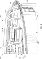
- FIGS. 17-25 illustrate additional features of the system that can be included to provide, as an example, variable or different binder density throughout a component, coatings of the component, certain detailed features printed into the component (such as cooling features and/or venting capabilities), as well as structural features.
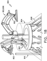
- the additive manufacturing system 800 includes a plurality of print heads 802 capable of dispensing at least one binder, such as a plurality of different binders, in varying densities onto the particulate in multiple locations to consolidate at least a portion of the particulate to form the component having a variable binder density throughout.
- the print heads 802 are configured to form a mold 804 that can be used in a casting process as described herein. Accordingly, in certain embodiments, the print heads 802 are capable of ejecting a programmed amount of binder that can vary in density throughout the printed part.
- the varying amount of binder can effectively create a gray-scale of binder rather than black and white.
- the binder density can be varied at multiple locations within the printed part such that, as an example, dense binder can be applied where structural strength is required, whereas sparse binder can be applied where strength is not needed.
- the cost of the mold 804 can be reduced since the binder is a costly component thereof.
- the strength, thermal conductivity, and gas permeability may be tailored to specific locations in the mold 804 using this technique.
- local weak spots may be intentionally incorporated in the mold 804, creating a line of weakness therein that allows for easier breakout of the part after casting.
- the print heads 802 illustrated in FIGS. 17 and 18 can be configured to operate similar to the system 300 described in FIGS 7 and 8 .
- certain of the print head(s) 802 can be configured to dispense a first binder through respective binder jet(s) onto the particulate to consolidate at least a portion of the particulate to form the component.
- such print head(s) 802 can be used to form details of the component.
- other of the print heads 802 may be configured for dispensing a second binder (which can be the same or different from the first binder as needed) for forming other, less detailed portions of the component.
- At least one of the print heads 102 can be configured for a variety of printing functions to form a variety of useful features into the component (e.g. the mold 804).
- at least one of the print heads 102 can be configured for dispensing the at least one binder onto the particulate to form a support structure 808 for the component, one or more chills 810 in the component, one or more vents 812 in the component, one or more channels 814 in the component, one or more tubes in the component, one or more protrusions, one or more holes, and/or any suitable feature that can be formed using the methods described herein, which can vary based on a desired design of the component.
- the component may be the mold 804 that can be used to form a casted metal part.
- Sand casting molds such as mold 804 are often coated with refractory materials prior to casting the metal to form the final part. Such coatings are needed because the friction and temperature of the molten metal poured into the mold would otherwise destroy the particulate used to form the mold. For conventional systems, these coatings are often sprayed on.
- one of the print heads 802 described herein can be configured to apply or otherwise form a coating 828 onto to the mold 804 before casting the metal part.
- the print heads 102 described herein may be different such that different print heads can be configured to dispense different binders, at least one of which being capable of forming the coating 828.
- the materials needed to form the coating 828 may include, as an example, ceramic.
- any additional materials may also be used for forming the coatings described herein.
- At least one of the print heads 102 is configured to dispense at least one binder onto the particulate to form a feeding system 816 for receiving a molten metal for forming the casted metal part.
- at least one of the print heads 102 of the additive manufacturing system 800 can form the one or more chills 810, the one or more vents 812, and/or the feeding system 816 (and associated channels 814) as part of or into the mold 804.
- FIG. 19A illustrates a conventional system for casting a component
- FIG. 19B illustrates the additive manufacturing system 800 according to the present disclosure
- the conventional system utilizes off-the-shelf ceramic piping for the molten metal feeding system, that include hard turns at the pipe corners
- the additive manufacturing system 800 according to the present disclosure is capable of printing the mold 804 to include the feeding system 816 for the molten metal, the support structure 808 of the mold, and/or any required vents 812.
- certain disadvantages of the conventional system (such as hard turns in the piping) can be eliminated.
- the customized shape improves metal flow and speed control, reduces splashes and erosion, and provides numerous other benefits.
- pre-assembly is eliminated.
- At least one of the print heads 102 can be configured to dispense the binder(s) to form the support structure 808 for the mold 804.
- Example support structures 808 for the mold 804 are illustrated, at least, in FIGS. 17-20 , 22 , 24 , and 25 . More specifically, in an embodiment, the support structure 808 of the mold 804 may have any suitable configuration, such as a lattice configuration as shown throughout the figures.
- the system 800 does not require sand packing to support the printed mold in place. Rather, the additive manufacturing system 800 is configured to print an optimized structure using, at least one of the print heads 102 as an example, that includes a stronger binder material. Accordingly, the stronger binder material is configured to withstand the weight of the mold 804 and the pressures of the casting process.
- the additive manufacturing system 800 may also be configured to print one or more three-dimensional chills 810 of various materials, sizes and/or shapes into the component.
- Conventional chills generally refer to metal or graphite blocks or bricks that are placed in a mold in locations where it is desired to cool the liquid metal more effectively than sand alone. Thus, the liquid metal contacts, either directly or indirectly, the chill(s) and loses heat more quickly in that area.
- the desired locations are determined, for example, via modeling.
- the chills can be printed directly into the mold. More specifically, as shown, an example printed chill assembly 810 arranged in the mold 804 is illustrated. Thus, with the additive manufacturing system 800 described herein, the chills 810 can be printed in place to improve cooling efficiency of the casted part. Furthermore, in certain embodiments, the chills 810 may be printed using the particulate dispenser assembly 314, which includes the bulk dispenser 313 and the vacuum nozzle 315 described herein (described in reference to FIGS. 7 and 8 ). Thus, in such embodiments, when the component (e.g.
- the print heads 102 may skip over certain locations where a chill needs to be located such that the binder does not consolidate the particulate in such locations.
- the vacuum nozzle 315 can be used to remove particulate in these locations.
- Another print head capable of dispensing a different binder can then dispense the chill material into the locations to form the chills.
- the chill material may include a graphene powder mixed with a binder in a slurry. Accordingly, the present disclosure allows for custom chills to be printed in place.
- the chill 810 may have one or more features, such as fingers, for improving cooling efficiency thereof.
- one or more channels 818 can also be built into the printed mold 804 through which a cooling medium 820 can be driven.
- a cooling medium 820 can be driven.
- Such channels 818 are configured to reduce cooling time of the casted part.
- Such cooling channels 818 can be easily tailored to the local needs inside the mold 804 and can be as complex as necessary.
- the cooling medium can be supplied to the chills or to any specific sections of the casting via the channels 818.
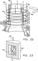
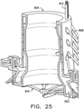
- FIGS. 23-25 various views of a complete printed mold 804 for use in a casting process as described herein is illustrated.
- FIG. 23 illustrates a partial view of a mold wall of the mold 804 according to the present disclosure
- FIG. 24 illustrates an example of one embodiment of a printed layer of the mold 804 according to the present disclosure
- FIG. 25 illustrates a partial, internal perspective view of the mold 804 according to the present disclosure.
- molten metal is poured into the feeding system 816 to fill the cavity 822 of the mold 804.
- Gases may be given off as the molten metal comes into contact with the sand/binder composite. Such gases must be vented to avoid buildup of pressure within the mold 804 to avoid failure of the mold 804.
- the printed vents 812 and/or certain areas of more porous material can be included in the mold 804 using the techniques described herein. These vents 812 may also be tailored to direct the venting gases from specific locations to safe location on the mold surface.
- the mold walls of the mold 804 can be at least partially hollowed out and provided with a lattice structure 824 therein (e.g. which may be printed therein) to maintain structural integrity thereof, while leaving unbound sand inside, thereby improving gas permeability (e.g. gas flow 826) through the mold 804.
- the additive manufacturing system is able to fabricate objects of any complexity and having various binder densities, shapes, etc.
- the additive manufacturing system is able to provide a multiple helical fabrication process which may fabricate the objects in less time than at least some known additive manufacturing systems.
- the additive manufacturing system is able to be shipped to remote sites and assembled because the support structure, binder jet print heads, particulate dispensers, recoater assemblies, and actuators are modular components. The mold described herein can then be formed onsite and does not require shipping.
- An exemplary technical effect of the methods, systems, and apparatus described herein includes at least one of: a) reducing the time required to fabricate components using an additive manufacturing system, b) providing an additive manufacturing system that is able to fabricate components of any complexity, c) providing an additive manufacturing system that allows a consolidation device and a recoater assembly to operate simultaneously during fabrication of a component, d) simplifying the mechanisms required to deposit particulate onto the build platform, e) reducing the cost of additively manufacturing a component, and f) providing additive manufacturing systems that are modular and able to fabricate components in situ.
- additive manufacturing systems are described above in detail.
- the additive manufacturing systems, and methods of using and manufacturing such systems are not limited to the specific embodiments described herein, but rather, components of systems and/or steps of the methods may be utilized independently and separately from other components and/or steps described herein.
- the methods may also be used in combination with other additive manufacturing systems, and are not limited to practice with only the additive manufacturing systems, and methods as described herein. Rather, an embodiment can be implemented and utilized in connection with many other additive manufacturing systems.
Landscapes
- Engineering & Computer Science (AREA)
- Chemical & Material Sciences (AREA)
- Materials Engineering (AREA)
- Manufacturing & Machinery (AREA)
- Mechanical Engineering (AREA)
- Physics & Mathematics (AREA)
- Optics & Photonics (AREA)
- Automation & Control Theory (AREA)
- Powder Metallurgy (AREA)
Abstract
Description
- The present disclosure relates in general to additive manufacturing systems and, more particularly, to additive manufacturing systems including a binder jet print head that rotates relative to a build platform.
- At least some known additive manufacturing systems involve the consolidation of a particulate to fabricate a component. Such techniques facilitate producing complex components from particulate materials at a reduced cost and with improved manufacturing efficiency. At least some known additive manufacturing systems fabricate components using one or more binder jet print heads that dispense a binder onto a particulate. In addition, in at least some additive manufacturing systems, one or more actuators are used to move the build platform during fabrication of the component. However, the size of the fabricated components is limited by the configuration of the binder jet print heads, the actuators, and the build platform.
- In addition, in at least some known additive manufacturing systems, a recoater is used to distribute the particulate on the build platform. For example, in some embodiments, a recoater moves the particulate from a container onto and across the build platform. The recoater and the binder jet print head are operated at separate times, because the binder jet print head cannot consolidate the particulate while the recoater is spreading the particulate. As a result, the time required for fabricating the components is increased to accommodate sequential operation of the recoater and the binder jet print head.
- Accordingly, there is a need for an improved additive manufacturing system and methods of operating same. In particular, an additive manufacturing system that includes a binder jet print head that allows for fabrication of components of any size and having varying characteristics (e.g. strength, stiffness, materials, etc.) throughout in a reduced time would be welcomed in the art.
- Aspects and advantages of the disclosure will be set forth in part in the following description, or may be obvious from the description, or may be learned through practice of the disclosure.
- In one aspect, the present disclosure is directed to an additive manufacturing system. The additive manufacturing system includes a build platform configured to receive a particulate, a particulate dispenser assembly configured to dispense or remove the particulate to or from the build platform, and a plurality of print heads each having at least one binder jet. The binder jets of the plurality of print heads are configured to dispense at least one binder in varying densities onto the particulate in multiple locations to consolidate at least a portion of the particulate to form the component having a variable binder density throughout. The additive manufacturing system also includes a plurality of arms extending at least partially across the build platform and configured to support the plurality of print heads and at least one actuator assembly configured to rotate at least one of the plurality of print heads and the build platform about a rotation axis extending through the build platform and move at least one of the plurality of print heads and the build platform in a build direction perpendicular to the build platform as part of a helical build process for the component.
- In another aspect, the present disclosure is directed to a method of fabricating a component using an additive manufacturing system. The method includes depositing a particulate on a build platform, rotating at least one recoater blade relative to the build platform about a rotation axis extending through the build platform so as to disperse the particulate onto the build platform, rotating a plurality of print heads relative to the build platform about the rotation axis, the plurality of print heads each including at least one nozzle, and dispensing, via a plurality of binder jets of a plurality of print heads, at least one of binder in varying densities onto the particulate in multiple locations to consolidate at least a portion of the particulate to form the component having a variable binder density throughout.
- These and other features, aspects and advantages of the present disclosure will become better understood with reference to the following description and appended claims. The accompanying drawings, which are incorporated in and constitute a part of this specification, illustrate embodiments of the disclosure and, together with the description, serve to explain the principles of the disclosure.
- A full and enabling disclosure of the present disclosure, including the best mode thereof, directed to one of ordinary skill in the art, is set forth in the specification, which makes reference to the appended figures, in which:
-
FIG. 1 illustrates a perspective view of one embodiment of an additive manufacturing system including at least one rotating binder jet print head according to the present disclosure; -
FIG. 2 illustrates a perspective view of another embodiment of an additive manufacturing system including at least one rotating binder jet print head according to the present disclosure; -
FIG. 3 illustrates an enlarged perspective view of a portion of the additive manufacturing system shown inFIG. 1 ; -
FIG. 4 illustrates a block diagram of the additive manufacturing system shown inFIGS. 1 and3 ; -
FIG. 5 illustrates a schematic plan view of an embodiment of an additive manufacturing system including at least one rotating binder jet print head and a feed system according to the present disclosure; -
FIG. 6 illustrates a schematic side view of the additive manufacturing system shown inFIG. 5 ; -
FIG. 7 illustrates a perspective view of an embodiment of an additive manufacturing system including a rotating binder jet print head and a plurality of articulated arms according to the present disclosure; -
FIG. 8 illustrates a detailed, perspective view of an embodiment of particulate dispenser assembly of an additive manufacturing system according to the present disclosure; -
FIG. 9 illustrates a flow chart of an exemplary method of fabricating a component using an additive manufacturing system including a rotating binder jet print head; -
FIG. 10 illustrates a schematic perspective view of a mold assembled from mold portions fabricated using an additive manufacturing system including a rotating binder jet print head; -
FIG. 11 illustrates a flow chart of an exemplary method of casting a component using the mold shown inFIG. 10 ; -
FIG. 12 illustrates a perspective view of an exemplary embodiment of a particulate feed and dispenser system for an additive manufacturing system including a rotating binder jet print head; -
FIG. 13 illustrates an enlarged perspective view of a portion of the particulate feed and dispenser system shown inFIG. 12 ; -
FIG. 14 illustrates a perspective view of an exemplary embodiment of a recoater assembly for an additive manufacturing system including a rotating binder jet print head; -
FIG. 15 illustrates an enlarged perspective view of a portion of the recoater assembly shown inFIG. 14 ; -
FIG. 16 illustrates a schematic side view of an additive manufacturing system including a rotating feed system; -
FIG. 17 illustrates a perspective view of another embodiment of an additive manufacturing system including a rotating binder jet print head and a plurality of articulated arms according to the present disclosure; -
FIG. 18 illustrates a perspective view of yet another embodiment of an additive manufacturing system according to the present disclosure, particularly illustrating the system as it forms a component; -
FIGS 19A-19B illustrate a conventional casting system for forming a component and one embodiment of an additive manufacturing system according to the present disclosure, respectively; -
FIG. 20 illustrates a perspective view of an embodiment of a casting mold formed via an additive manufacturing system according to the present disclosure; -
FIG. 21 illustrates a perspective view of an embodiment of a chill printed into a casting mold formed via an additive manufacturing system according to the present disclosure; -
FIG. 22 illustrates a perspective view of an embodiment of a casting mold formed via an additive manufacturing system according to the present disclosure, particularly illustrating channels formed into the mold; -
FIG. 23 illustrates a partial, perspective view of an embodiment of a hollowed mold wall of a casting mold formed via an additive manufacturing system according to the present disclosure; -
FIG. 24 illustrates a partial, perspective view of an embodiment of a layer of a casting mold formed via an additive manufacturing system according to the present disclosure; and -
FIG. 25 illustrates a partial, perspective view of an embodiment of a casting mold formed via an additive manufacturing system according to the present disclosure. - Reference now will be made in detail to embodiments of the disclosure, one or more examples of which are illustrated in the drawings. Each example is provided by way of explanation of the disclosure, not limitation of the disclosure. In fact, it will be apparent to those skilled in the art that various modifications and variations can be made in the present disclosure without departing from the scope or spirit of the disclosure. For instance, features illustrated or described as part of one embodiment can be used with another embodiment to yield a still further embodiment. Thus, it is intended that the present disclosure covers such modifications and variations as come within the scope of the appended claims and their equivalents.
- In the following specification and the claims, reference will be made to a number of terms, which shall be defined to have the following meanings.
- "Optional" or "optionally" means that the subsequently described event or circumstance may or may not occur, and that the description includes instances where the event occurs and instances where it does not.
- Approximating language, as used herein throughout the specification and claims, may be applied to modify any quantitative representation that could permissibly vary without resulting in a change in the basic function to which it is related. Accordingly, a value modified by a term or terms, such as "about," "substantially," and "approximately," are not to be limited to the precise value specified. In at least some instances, the approximating language may correspond to the precision of an instrument for measuring the value. Here and throughout the specification and claims, range limitations may be combined and/or interchanged, such ranges are identified and include all the sub-ranges contained therein unless context or language indicates otherwise.
- Additive manufacturing processes and systems include, for example, and without limitation, vat photopolymerization, powder bed fusion, binder jetting, material jetting, sheet lamination, material extrusion, directed energy deposition and hybrid systems. These processes and systems include, for example, and without limitation, SLA - Stereolithography Apparatus, DLP - Digital Light Processing, 3SP - Scan, Spin, and Selectively Photocure, CLIP - Continuous Liquid Interface Production, SLS - Selective Laser Sintering, DMLS - Direct Metal Laser Sintering, SLM - Selective Laser Melting, EBM - Electron Beam Melting, SHS - Selective Heat Sintering, MJF - Multi-Jet Fusion, 3D Printing, Voxeljet, Polyjet, SCP - Smooth Curvatures Printing, MJM - Multi-Jet Modeling ProJet, LOM - Laminated Object Manufacture, SDL - Selective Deposition Lamination, UAM - Ultrasonic Additive Manufacturing, FFF - Fused Filament Fabrication, FDM - Fused Deposition Modeling, LMD - Laser Metal Deposition, LENS - Laser Engineered Net Shaping, DMD - Direct Metal Deposition, Hybrid Systems, and combinations of these processes and systems. These processes and systems may employ, for example, and without limitation, all forms of electromagnetic radiation, heating, sintering, melting, curing, binding, consolidating, pressing, embedding, and combinations thereof.
- Additive manufacturing processes and systems employ materials including, for example, and without limitation, polymers, plastics, metals, ceramics, sand, glass, waxes, fibers, biological matter, composites, and hybrids of these materials. These materials may be used in these processes and systems in a variety of forms as appropriate for a given material and the process or system, including, for example, and without limitation, as liquids, solids, powders, sheets, foils, tapes, filaments, pellets, liquids, slurries, wires, atomized, pastes, and combinations of these forms.
- In general, the systems and methods described herein include an additive manufacturing system including a rotating binder jet print head. The binder jet print head is configured to rotate relative to a build platform and dispense a binder onto a particulate to consolidate the particulate. As the binder jet print head operates, a particulate dispenser and a recoater assembly are configured to dispense and spread particulate on the build platform to provide a continuous fabrication process. In addition, the additive manufacturing system includes a support structure that supports the binder jet print head, the particulate dispenser, and the recoater assembly. An actuator is configured to rotate and raise the binder jet print head, the particulate dispenser, and the recoater assembly relative to the build platform as the additive manufacturing system fabricates a component on the build platform. As a result, the additive manufacturing system is able to fabricate objects of any geometric complexity within the size of the printing system. In addition, the additive manufacturing system is able to provide a multiple helix fabrication process which may fabricate the objects in less time than at least some known additive manufacturing systems. Moreover, the additive manufacturing system is able to be shipped to remote sites and assembled because the support structure, binder jet print heads, particulate dispensers, recoater assemblies, and actuators are modular components.
- Referring now to the drawings,
FIG. 1 illustrates a perspective view of an embodiment of anadditive manufacturing system 100 including at least one rotating binderjet print head 102 according to the present disclosure.FIG. 2 illustrates a perspective view of another embodiment of anadditive manufacturing system 100 including at least one rotating binderjet print head 102 according to the present disclosure.FIG. 3 illustrates an enlarged perspective view of a portion ofadditive manufacturing system 100 ofFIG. 1 .FIG. 4 illustrates a block diagram of an embodiment of theadditive manufacturing system 100 according to the present disclosure. As shown particularly inFIG. 1 , a coordinate system of theadditive manufacturing system 100 includes an X-axis, a Y-axis, and a Z-axis. Thus, theadditive manufacturing system 100 is configured to build objects, for example, a mold 500 (shown inFIG. 10 ) for casting a component 516 (shown inFIG. 11 ). Though thesystem 100 described herein may be used to form any suitable component, it should be understood that thesystem 100 may be particularly useful for forming various wind turbine components. - In an embodiment, the
additive manufacturing system 100 includes at least one binderjet print head 102 for consolidating particulate. Further, theadditive manufacturing system 100 is configured for fabricating an object or component using an additive manufacturing process by depositing a binder onto particulate from binder jet print heads 102. For example, each binderjet print head 102 includes a plurality of outlets orjets 108 and is configured to dispense a binder throughjets 108 onto the particulate. Alternatively, theadditive manufacturing system 100 may include any consolidation device that facilitates consolidation of a material using any of the processes and systems described herein. - In an embodiment, the
additive manufacturing system 100 further includes at least onerecoater assembly 110 and at least oneparticulate dispenser 112. Eachrecoater assembly 110 andparticulate dispenser 112 may be associated with a respective rotating binderjet print head 102. In one embodiment, theadditive manufacturing system 100 includes threerecoater assemblies 110, threeparticulate dispensers 112, and three binder jet print heads 102. In alternative embodiments, theadditive manufacturing system 100 may include any number of binder jet print heads 102,recoater assemblies 110, and/orparticulate dispensers 112 that enables theadditive manufacturing system 100 to operate as described herein. For example, in some embodiments, asingle recoater assembly 110 and/orparticulate dispenser 112 may be associated with a plurality of binder jet print heads 102. In further embodiments, theadditive manufacturing system 100 includes a single binderjet print head 102. - Also, in an embodiment, the binder jet print heads 102, the
recoater assemblies 110, and theparticulate dispensers 112 may be coupled to and supported by asupport structure 114. Further, as shown, thesupport structure 114 may include at least onearm 116 extending at least partially acrossbuild platform 104 and configured to support at least one binderjet print head 102. In an embodiment, thesupport structure 114 may include acenter support 118 and threearms 116 equally spaced aboutcenter support 118. Thearms 116 extend radially outward fromcenter support 118. Further, therecoater assemblies 110 and theparticulate dispensers 112 may be coupled toarms 116 and positioned adjacent associated binder jet print heads 102 onarms 116. In an embodiment, eacharm 116 supports one binderjet print head 102, onerecoater assembly 110, and oneparticulate dispenser 112. In alternative embodiments,support structure 114 includes anyarm 116 that enablesadditive manufacturing system 100 to operate as described herein. For example, in some embodiments, thesupport structure 114 includes arms that supportrecoater assemblies 110 and/orparticulate dispensers 112 and are distinct fromarms 116 that support binder jet print heads 102. - Moreover, in an embodiment, as shown in
FIGS. 1 and3 , thesupport structure 114 may further include atrack 120 and a plurality oflegs 122 that supporttrack 120 at an adjustable height abovebuild platform 104. Thetrack 120 extends around the circumference of thebuild platform 104 and is configured to supportarms 116 asarms 116 are rotated about arotation axis 124. In addition, thelegs 122 are positionable to adjust the height ofsupport structure 114 relative to buildplatform 104 during operation of theadditive manufacturing system 100. For example, the angle of eachleg 122 relative torotation axis 124 is adjustable to change the height ofsupport structure 114 and therefore the distance betweenbuild platform 104 and binder jet print heads 102,recoater assemblies 110, andparticulate dispensers 112. In some embodiments, a vertical actuator may be used to extend/shorten the length of eachleg 122. In alternative embodiments, theadditive manufacturing system 100 includes anysupport structure 114 that enables theadditive manufacturing system 100 to operate as described herein. - More specifically, in another embodiment, as shown in
FIG. 2 , theadditive manufacturing system 100 may be secured to alifting system 115 for lifting and/or lowering theadditive manufacturing system 100 relative to buildplatform 104 such that a component having any suitable height can be manufactured. In particular, as shown, thelifting system 115 may include opposingsupport structures support beam 121 extending therebetween. Further, as shown, each of thesupport structures track system support beam 121 may be secured to each of thetracks additive manufacturing system 100 can be secured to thesupport beam 121. Accordingly, by raising or lower thesupport beam 121, theadditive manufacturing system 100 can also be raised or lowered to any suitable height. It should be further understood that operation of thelifting system 115 can be accomplished using any suitable control system to automate the system. - During operation of the
additive manufacturing system 100, particulate is supplied byparticulate dispensers 112 and spread evenly over thebuild platform 104 using therecoater assemblies 110. Thus, therecoater assemblies 110 are configured to control the height of the particulate relative to the height of the previous revolution of the helix and facilitate removal of excess particulate material. The binder jet print heads 102 consolidate a first portion of particulate to form a cross-sectional layer of a component. Further, therecoater assemblies 110 and the binder jet print heads 102 are able to operate simultaneously to distribute and consolidate particulate because therecoater assemblies 110 are positioned in front of and rotate in coordination with respective binder jet print heads 102. During selective consolidation of the layer of particulate, thesupport structure 114 is raised to elevate the binder jet print heads 102, therecoater assemblies 110, and theparticulate dispensers 112 as particulate is spread over thebuild platform 104 and the partial component to allow continuous consolidation of particulate by the binder jet print heads 102. The process is continued until the component is completely built up from the consolidated portion of particulate. - Also, in an embodiment, as shown particularly in
FIG. 4 , at least a portion of thesupport structure 114 may be moved by anactuator system 126. In an embodiment, theactuator system 126 includes afirst actuator assembly 128 and asecond actuator assembly 130. For example, in an embodiment, thefirst actuator assembly 128 is configured to rotate thearm 116 of thesupport structure 114 about therotation axis 124 and thesecond actuator assembly 130 is configured to movearm 116 in the Z-direction (i.e., normal to a top surface of the build platform 104), also referred to as the build direction. In some embodiments, theactuator system 126 is configured to move at least one binderjet print head 102 in a radial direction relative torotation axis 124. For example, in some embodiments, the binder jet print heads 102 are movable along the length ofarms 116 during operation of theadditive manufacturing system 100. - In particular embodiments, each
actuator assembly additive manufacturing system 100 includes anyactuator system 126 that enables theadditive manufacturing system 100 to operate as described herein. For example, in some embodiments,actuator system 126 is configured to rotatebuild platform 104 aboutrotation axis 124 and/or movebuild platform 104 in the build direction. - In addition, in an embodiment, the
particulate dispenser 112 is positioned to deposit particulate in front ofrecoater assembly 110. In alternative embodiments, particulate is deposited onto thebuild platform 104 in any manner that enables theadditive manufacturing system 100 to operate as described herein. - Also, in an embodiment, at least one
recoater blade 132 ofrecoater assembly 110 is positioned to contact particulate in front of the respective binderjet print head 102 and distribute particulate acrossbuild platform 104. For example, therecoater blade 132 may extend at least partially along a radius of thebuild platform 104. In an embodiment, therecoater blade 132 is rotated with the binderjet print head 102 relative to thebuild platform 104. As a result, therecoater blade 132 contacts particulate and directs particulate along the length of therecoater blade 132 across thebuild platform 104 during operation of theadditive manufacturing system 100. In addition, therecoater assembly 110 is configured to maintain a uniform thickness of each layer of particulate on thebuild platform 104 above the prior consolidated layer. In some embodiments, each layer may have a thickness in a range of about 10 microns to about 2000 microns. In alternative embodiments,recoater assembly 110 includes anyrecoater blade 132 that enables theadditive manufacturing system 100 to operate as described herein. - Moreover, in an embodiment, the
additive manufacturing system 100 further includes awall 134 extending aroundbuild platform 104 to define a build container. In an embodiment, as shown inFIG. 1 , thebuild platform 104 may have a generally circular shape. Further, as shown, thewall 134 may be generally cylindrical and fully surrounds particulate on thebuild platform 104. In alternative embodiments, thebuild platform 104 and/or thewall 134 may be any shapes that facilitate operation of theadditive manufacturing system 100 as described herein. In further embodiments, thewall 134 may surround a portion of particulate and/or may be coupled to any other wall or component that facilitates operation of theadditive manufacturing system 100 as described herein. In addition, in some embodiments, theadditive manufacturing system 100 includes an inner particulate containment wall (not shown) that reduces the amount of particulate required to assemble the component. The inner particulate containment wall may be cylindrical. In embodiments including an inner particulate containment wall, particulate may be dispensed adjacent the inner particulate containment wall and consolidated to form a shape such as a pipe shape having a cavity near the central region ofbuild platform 104. - Also, in an embodiment, the binder jet print heads 102 are configured to consolidate particulate on different areas of
build platform 104 and are configured to consolidate different portions of particulate simultaneously. Thesupport structure 114 and the binder jet print heads 102 are able to rotate at an increased speed during fabrication of a component because a plurality of binder jet print heads 102 are used to consolidate particulate. In alternative embodiments, theadditive manufacturing system 100 includes any number of binder jet print heads 102 including a single binderjet print head 102. - Moreover, in an embodiment, as shown in
FIG. 4 , theadditive manufacturing system 100 may include a computer control system, orcontroller 136. More specifically, as shown, thecontroller 136 includes aprocessor 138, amemory 140, and auser interface 142 including aninput device 144 and adisplay 146. Further, thecontroller 136 controls operation of the binderjet print head 102 to facilitate directing binder onto the surface of particulate of a build layer to form a layer of the component. For example, thecontroller 136 controls the amount of binder that is dispensed through each nozzle orjet 108 of the binder jet print heads 102. - In an embodiment, the
additive manufacturing system 100 may be operated to fabricate a component from a computer modeled representation of the 3D geometry of the component. The computer modeled representation may be produced in a computer aided design (CAD) or similar file. The CAD file of the component is converted into a format that includes a plurality of build parameters for one or more helical layers of the component. For example, a build layer of the component includes a particulate to be consolidated (or a particulate slurry) by theadditive manufacturing system 100. In an embodiment, the component is modeled in a desired orientation relative to the origin of the coordinate system used in theadditive manufacturing system 100. The geometry of the component is sliced into one or more helical layers. Inkjet firing sequences are generated across the geometry of a respective layer. The build parameters are applied for each firing sequence to fabricate that layer of the component from particulate. Once the process is completed, an electronic computer build file (or files) is generated, including all of the layers. The build file is loaded into thecontroller 136 of theadditive manufacturing system 100 to control the system during fabrication of each layer. - After the build file is loaded into the
controller 136, theadditive manufacturing system 100 is operated to generate the component by implementing the additive manufacturing process, such as a binder jet printing method. The exemplary additive manufacturing process does not use a pre-existing article as the precursor to the final component, rather the process produces components from a raw material in a configurable form, such as particulate. For example, and without limitation, a mold can be additively manufactured using sand that is consolidated using a binder. Theadditive manufacturing system 100 enables fabrication of components using a broad range of materials, for example, and without limitation, metals, ceramics, glass, and polymers. - Moreover, in an embodiment, during operation of the
additive manufacturing system 100, thecontroller 136 is able to control the position of support structure 114 (or the support beam 121) to adjust the height of binderjet print head 102. For example,FIG. 1 showssupport structure 114 in an initial position with the binderjet print head 102 positioned adjacent thebuild platform 104.FIG. 3 shows thesupport structure 114 in an elevated position with the binderjet print head 102 located a distance from thebuild platform 104. In an embodiment, thesupport structure 114 is moved vertically by adjusting the positions or lengths oflegs 122 using theactuator system 126. In alternative embodiments, thesupport structure 114 is moved in any manner that enables theadditive manufacturing system 100 to operate as described herein. In an alterative embodiment,FIG. 2 shows thesupport beam 121 in an elevated position. - In some embodiments, the
controller 136 controls the rotational speed and/or vertical movement speed of the binder jet print heads 102, theparticulate dispensers 112, and/or therecoater blades 132 based on operating parameters of theadditive manufacturing system 100. Operating parameters of theadditive manufacturing system 100 include, for example and without limitation, the configuration of theparticulate dispensers 112, the configuration ofrecoater assembly 110, number and types of the binder jet print heads 102, and size of thebuild platform 104. - In addition, in an embodiment, the
controller 136 coordinates the rotational speeds of the binder jet print heads 102, therecoater blades 132, and/or theparticulate dispensers 112 to accommodate local variations in build time requirements. For example, thecontroller 136 determines layers or sections of layers that require more or less build time due to variations in the thickness of angular sectors of the component and thecontroller 136 adjusts the rotation rate of the binder jet print heads 102, therecoater blades 132, and/or theparticulate dispensers 112 to maintain the sections within the build area for the required time for the binderjet print head 102 to complete consolidation of each section. - Also, in an embodiment, as shown in
FIGS. 1 and3 , theadditive manufacturing system 100 may include acleaning assembly 148 positionable adjacent each binderjet print head 102 and configured to clean the binderjet print head 102. For example, the cleaningassembly 148 is coupled toarm 116 and is able to clean the binderjet print head 102 without requiring disassembly of theadditive manufacturing system 100. - Referring now to
FIG. 5 , a schematic plan view of another embodiment of anadditive manufacturing system 200 according to the present disclosure is illustrated. As shown, theadditive manufacturing system 200 includes at least one rotating binderjet print head 202 and afeed system 204. Further, theadditive manufacturing system 200 includes binder jet print heads 202, afeed system 204, at least oneparticulate dispenser 206, at least onerecoater assembly 208, abuild platform 210, and asupport structure 212. Thesupport structure 212 includes a plurality ofarms 214 that support binder jet print heads 202,particulate dispensers 206, andrecoater assemblies 208. Binder jet print heads 202,particulate dispensers 206, andrecoater assemblies 208 rotate relative to buildplatform 210 about arotation axis 216 extending through thebuild platform 210. - Referring now to
FIG. 6 , a schematic side view of one embodiment of theadditive manufacturing system 200 ofFIG. 5 is illustrated. During operation of theadditive manufacturing system 200,particulate dispensers 206deposit particulate 218 on thebuild platform 210 andrecoater assemblies 208spread particulate 218 evenly over thebuild platform 210 asparticulate dispensers 206 andrecoater assemblies 208 rotate relative to buildplatform 210. Therecoater assemblies 208 are configured to control the height ofparticulate 218 relative to the height of the previous revolution of the helix and facilitate removal ofexcess particulate 218. The binder jet print heads 202 selectively consolidate particulate 218 to form a cross-sectional layer of a component. During selective consolidation of the layer ofparticulate 218,arms 214 ofsupport structure 212 are raised to elevate binder jet print heads 202,recoater assemblies 208, andparticulate dispensers 206 asparticulate 218 is spread overbuild platform 210 and the partial component to allow continuous consolidation ofparticulate 218 by binder jet print heads 202. The process is continued until the component is completely built up from the consolidated portion ofparticulate 218. - In addition, in an embodiment, each
particulate dispenser 206 may include an upper hopper orreservoir 220, aconduit 222 coupled to anoutlet 224 ofupper hopper 220, a lower hopper orreservoir 226 coupled toconduit 222, and avalve 228 configured to regulate flow of the particulate fromupper hopper 220 and throughconduit 222 tolower hopper 226. In an embodiment, theupper hopper 220 and theconduit 222 are positioned above thelower hopper 226 and particulate is gravity fed to thelower hopper 226. In some embodiments, a sensor (not shown) such as a weight scale or proximity switch provides feedback for use in controllingparticulate dispenser 206. For example, theparticulate dispenser 206 may be controlled to provide appropriate feed rates ofparticulate 218 to thebuild platform 210 and regulate the amount ofparticulate 218 on thebuild platform 210. - In addition, in an embodiment, each
particulate dispenser 206 may include a trough orconduit 230 extending along therespective arm 214 and aconveyor apparatus 232 configured to convey particulate 218 throughtrough 230. Eachtrough 230 is in flow communication with and receives particulate from the respectivelower hopper 226 ofparticulate dispenser 206.Conveyor apparatus 232 includes, for example and without limitation, a belt conveyor, an auger, and/or any other conveyor apparatus.Conveyor apparatus 232 carriesparticulate 218 along a length oftrough 230 so thatparticulate 218 is dispensed in a desired manner. For example, in some embodiments,additional particulate 218 is dispensed at locations spaced from the center ofbuild platform 210 because of the greater relative rotational speed ofparticulate dispenser 206 at distances spaced from the axis of rotation.Trough 230 includes a plurality ofoutlets 234 forparticulate 218 to exittrough 230 asconveyor apparatus 232 carriesparticulate 218 alongtrough 230.Conveyor apparatus 232 also carriesexcess particulate 218, i.e., particulate that is not dispensed throughoutlets 234, back along the length oftrough 230 towardslower hopper 226. In alternative embodiments,additive manufacturing system 200 includes anyparticulate dispenser 206 that enablesparticulate dispenser 206 to operate as described herein. - In an embodiment,
feed system 204 is configured to deliver particulate to eachparticulate dispenser 206.Feed system 204 includes asupply reservoir 236 and aparticulate transfer assembly 238 that is configured to transfer particulate fromsupply reservoir 236 to eachparticulate dispenser 206. For example,transfer assembly 238 includes a lift orconveyor apparatus 240 to carry particulate 218 toupper hopper 220. In an embodiment,feed system 204 is stationary relative to buildplatform 210. Accordingly, thefeed system 204 is positioned to align with eachparticulate dispenser 206 at a specific angular position along the rotational path ofparticulate dispensers 206. In some embodiments,particulate dispenser 206 pauses or stops at the designated rotational location to receiveparticulate 218. In further embodiments,feed system 204 delivers particulate 218 toparticulate dispenser 206 asparticulate dispenser 206 rotates. In alternative embodiments,additive manufacturing system 200 includes anyfeed system 204 that enablesadditive manufacturing system 200 to operate as described herein. For example, in some embodiments such as the embodiment shown inFIG. 15 ,particulate dispenser 206 may be positioned at the center ofsupport structure 212 rather than at the outer circumference ofsupport structure 212. - Also, in an embodiment, the
additive manufacturing system 200 includes anactuator system 242 configured to rotatesupport structure 212 aboutrotation axis 216 and raisesupport structure 212 in a direction perpendicular to buildplatform 210. For example,actuator system 242 includes a rotary actuator (not shown) configured to rotatesupport structure 212 on atrack 244. In addition, in an embodiment,actuator system 242 includes avertical actuator 246 configured to raisetrack 244, and thereforesupport structure 212 positioned ontrack 244, relative to buildplatform 210.Vertical actuator 246 includes a hydraulic actuator or any other actuator that enablesactuator system 242 to function as described herein. In alternative embodiments, theadditive manufacturing system 200 includes anyactuator system 242 that enables theadditive manufacturing system 200 to operate as described herein. - Referring now to
FIG. 15 , a schematic side view of another embodiment of anadditive manufacturing system 248 according to the present disclosure is illustrated. For example, as shown, theadditive manufacturing system 248 is similar to the additive manufacturing system 200 (shown inFIGS. 4 and5 ) exceptadditive manufacturing system 248 includes aparticulate dispenser 250 positioned in a center ofsupport structure 212 and aligned with a center ofbuild platform 210. In an embodiment, theparticulate dispenser 250 is mounted to and rotates withsupport structure 212. - In addition, in an embodiment, the
particulate dispenser 250 includes aconduit 252, a central hopper orreservoir 254 coupled toconduit 252, a trough orconduit 256 extending along eacharm 214, and aconveyor apparatus 258 configured to convey particulate 218 through eachtrough 256. Eachtrough 256 is in flow communication with and receives particulate fromcentral hopper 254 ofparticulate dispenser 250. In alternative embodiments, theadditive manufacturing system 200 includes anyparticulate dispenser 206 that enablesparticulate dispenser 206 to operate as described herein. - In an embodiment, the
feed system 204 is configured to deliver particulate 218 toparticulate dispenser 250. Specifically,particulate transfer assembly 238 extends fromsupply reservoir 236 across a radius ofbuild platform 210 toconduit 252 ofparticulate dispenser 250.Conduit 252 is configured to receiveparticulate 218 and direct particulate tocentral hopper 254 asparticulate dispenser 250 rotates relative to feedsystem 204. For example, in some embodiments,conduit 252 includes an inlet forparticulate 218 to enterconduit 252 fromtransfer assembly 238 and an outlet forparticulate 218 to be dispensed intocentral hopper 254. Also,conduit 252 includes a seal or valve such as a bellows seal to prevent leakage of particulate 218 fromconduit 252 and/or control particulate flow throughdispenser 250. In alternative embodiments,additive manufacturing system 248 includes anyfeed system 204 that enables theadditive manufacturing system 200 to operate as described herein. For example, in some embodiments,supply reservoir 236 is positioned at a center ofbuild platform 210. - Referring now to
FIG. 7 , a perspective view of an embodiment of anadditive manufacturing system 300 including at least one rotating first nozzle, e.g. binderjet print head 302, and a plurality of articulated arms is illustrated. As shown, theadditive manufacturing system 300 includes asupport structure 304 including acentral support 306 and a plurality of first articulatedarms 308 extending at least partly radially outward fromcentral support 306. The binder jet print heads 302 andrecoater assemblies 312 are coupled to ends of first articulatedarms 308. The first articulatedarms 308 are positionable to adjust the location of binder jet print heads 302 andrecoater assemblies 312 relative to abuild platform 316. In addition, the first articulatedarms 308 may be rotatably coupled tocentral support 306 such that the binder jet print heads 302 andrecoater assemblies 312 are rotatable relative to buildplatform 316. Therecoater assemblies 312 are coupled to the first articulatedarms 308 adjacent binder jet print heads 302 such thatrecoater assemblies 312 spread particulate in front of binder jet print heads 302 as first articulatedarms 308 rotate relative to buildplatform 316 aboutcentral support 306. - Also, in an embodiment, the
additive manufacturing system 300 may include at least oneparticulate dispenser assembly 314. In particular, as shown inFIGS. 7 and8 , theparticulate dispenser assembly 314 may optionally include abulk dispenser 313 and/or avacuum nozzle 315. Further, as shown, theparticulate dispenser assembly 314 may be coupled to a second articulatedarm 318 that allows positioning of theparticulate dispenser assembly 314 relative to thebuild platform 316. As such, theparticulate dispenser assembly 314 is able to move radially relative to build platform by the positioning second articulatedarm 318. Thus, in such embodiments, thebulk dispenser 313 may be configured to dispense particulate material in bulk therethrough, whereas thevacuum nozzle 315 is configured to remove particulate to and from the build platform. In such embodiments, thebulk dispenser 313 and thevacuum nozzle 315 may also be mounted to anend 319 of thesecond arm 318 at ahinge point 317. Accordingly, as shown inFIG. 8 , thebulk dispenser 313 and thevacuum nozzle 315 may be rotatable about thehinge point 317. Moreover, in an embodiment, thebulk dispenser 313 and thevacuum nozzle 315 may be spaced about by at least about 90 degrees as well as any other suitable angle to allow for the nozzle to operate as desired. - In some embodiments, the
bulk dispenser 313 can be fixed as the binder jet print heads 302 and therecoater assemblies 312 rotate relative to thebuild platform 316. Accordingly, particulate dispenser is able to deposit particulate for eachrecoater assembly 312 to spread acrossbuild platform 316 for the binder jet print heads 302 to consolidate. In alternative embodiments, theadditive manufacturing system 300 may include any particulate dispenser that enables theadditive manufacturing system 300 to operate as described herein. For example, in some embodiments, theadditive manufacturing system 300 includes a plurality of particulate dispensers. - Referring now to
FIG. 9 , a flow chart of an embodiment of amethod 400 of fabricating a component using the additive manufacturing system 100 (shown inFIGS. 1-4 ), the additive manufacturing system 200 (shown inFIGS. 5 and 6 ), or the additive manufacturing system 300 (shown inFIGS. 7-8 ) is illustrated. In reference toFIGS. 1-4 and9 , themethod 400 includes depositing 402 particulate onbuild platform 104. For example, particulate is deposited onbuild platform 104 usingparticulate dispenser 112.Particulate dispenser 112 is rotated relative to buildplatform 104 and deposits particulate in front ofrecoater blade 132 and binder jet print heads 102 relative to the direction of rotation ofparticulate dispenser 112. In some embodiments,particulate dispenser 112 receives particulate from feed system 204 (shown inFIGS. 5 and 6 ). In alternative embodiments, particulate is deposited onbuild platform 104 in any manner that enables theadditive manufacturing system 100 to operate as described herein. - In addition, the
method 400 includes rotating 404 at least onerecoater blade 132 relative to buildplatform 104 and contacting 406 particulate onbuild platform 104 using at least onerecoater blade 132 to distribute particulate acrossbuild platform 104. Also, themethod 400 includes rotating 408 at least one binderjet print head 102 relative to buildplatform 104 aboutrotation axis 124 extending throughbuild platform 104. For example, in some embodiments,arms 116 supporting binder jet prints head 102 andrecoater blades 132 are rotated aboutrotation axis 124 usingactuator system 126. In alternative embodiments,recoater blades 132 and/orrecoater blades 132 are rotated in any manner that enables theadditive manufacturing system 100 to operate as described herein. - Also, the
method 400 includes dispensing 410 a binder throughjet 108 onto particulate to consolidate at least a portion of particulate. In some embodiments, the particulate described herein may include sand and the binder may be configured to bind the sand together to form a component such as a portion of a mold. In further embodiments, the particulate may also include a slurry. For example, in an embodiment, the particular may include sand that is pre-impregnated with a catalyst, a ceramic slurry, or any suitable combinations. - Moreover, the
method 400 includes moving 412 at least one binderjet print head 102 in a direction perpendicular to buildplatform 104. For example,support structure 114 supports binder jet print heads 102,recoater blades 132, andparticulate dispensers 112 and is rotated and raised byactuator system 126 during operation of theadditive manufacturing system 100. - In some embodiments, the
build platform 104 is rotated relative to binderjet print head 102 and/or moved in the build direction during fabrication of the component. For example, in some embodiments,build platform 104 is rotated relative to binder jet print heads 102. In further embodiments,build platform 104 is lowered as binder jet print heads 102 or buildplatform 104 is rotated. - In an embodiment, the
method 400 allows binder jet print heads 102 andrecoater blades 132 to operate simultaneously and provide a helical build process in which a component is fabricated using a plurality of helical build layers. As a result, the time required to fabricate components using the additive manufacturing system 100 (shown inFIGS. 1-4 ), the additive manufacturing system 200 (shown inFIGS. 5 and 6 ), and/or the additive manufacturing system 300 (shown inFIG. 7 ) is reduced. - Referring now to
FIG. 10 , a schematic perspective view of an embodiment of amold 500 assembled from components fabricated using the additive manufacturing system 100 (shown inFIGS. 1-4 ), the additive manufacturing system 200 (shown inFIGS. 5 and 6 ), and/or the additive manufacturing system 300 (shown inFIGS. 7 and8 ) according to the present disclosure is illustrated. For example, as shown, theadditive manufacturing system layers 502 which are assembled intomold 500. In an embodiment,mold 500 is a sand mold and eachmold portion 502 is formed from sand. As a result,mold 500 may have an increased size and a reduced cost in comparison to molds formed from other materials. - Referring now to
FIG. 11 , a flow chart of one embodiment of amethod 504 of casting a component using the mold 500 (shown inFIG. 9 ) is illustrated. In reference toFIGS. 1 ,5 ,7 ,10 , and11 , themethod 504 may include fabricating 506first mold portion 502 using theadditive manufacturing system second mold portion 502 using theadditive manufacturing system - Also, the
method 504 includes supporting 510first mold portion 502 andsecond mold portion 502 with filler, such as sand. In some embodiments, unconsolidated particulate 218 (shown inFIG. 6 ) can be removed and filler sand, which may be less expensive than particulate 218, can be positioned around themold portions 502. In addition, in some embodiments, eachmold portion 502 may also be surrounded by a cask orflask 512. Also, in some embodiments, one or more chills (not shown) may be positioned on, adjacent, and/or inmold portions 502 to control the solidification of a component formed usingmold 500. Further discussion of the chills are provide herein below. In further embodiments, a coating may also be applied to at least a portion of themold portions 502, which is also discussed in more detail herein below. In alternative embodiments, themold portions 502 may be supported and treated in any manner that enables themold 500 to function as described herein. - In addition, the
method 504 includescoupling 514first mold portion 502 andsecond mold portion 502 together to assemblemold 500. In an embodiment,mold portions 502 may be stacked in a vertical arrangement. In alternative embodiments, themold portions 502 may be assembled in any manner that enablesmold 500 to function as described herein. Also, themethod 504 optionally includes repeating any ofsteps mold 500 from any number ofmold portions 502. Moreover, themethod 504 may include casting 516 acomponent 518 using themold 500. For example, in some embodiments, cavities in themold 500 may be filled with one or more precursor materials in liquid form and the materials are solidified to formcomponent 518. - Referring now to
FIG. 12 , a perspective view of one embodiment of a particulate feed anddispenser system 600 according to the present disclosure is illustrated. As shown, the particulate feed anddispenser system 600 may be used with the additive manufacturing system 100 (shown inFIGS. 1-3 ), the additive manufacturing system 200 (shown inFIGS. 4 and5 ), and/or the additive manufacturing system 300 (shown inFIGS. 7 and8 ). In alternative embodiments, the feed anddispenser system 600 may be used with any additive manufacturing system that enables feed anddispenser system 600 to function as described herein. - In an embodiment, the feed and
dispenser system 600 includes a plurality offeed assemblies 602 and a plurality ofdispenser assemblies 604. Eachdispenser assembly 604 is coupled to and receives particulate from arespective feed assembly 602. In addition, eachdispenser assembly 604 extends radially acrossbuild platform 606 and is configured to dispense particulate ontobuild platform 606. In addition, feed anddispenser system 600 includes arecoater assembly 608 coupled to eachdispenser assembly 604.Recoater assembly 608 is configured to spread particulate acrossbuild platform 606. In some embodiments, at least a portion of feed anddispenser system 600 is configured to rotate relative to buildplatform 606 asdispenser assemblies 604 dispense particulate and asrecoater assemblies 608 spread particulate acrossbuild platform 606. In alternative embodiments, feed anddispenser system 600 includes anydispenser assembly 604 and/orrecoater assembly 608 that enables particulate feed anddispenser system 600 to operate as described herein. -
FIG. 13 illustrates an enlarged perspective view of a portion of particulate feed anddispenser system 600. In an embodiment, eachdispenser assembly 604 includes aconduit 610 that receives particulate fromfeed assembly 602 and dispenses the particulate.Recoater assemblies 608 are coupled toconduit 610. Eachrecoater assembly 608 includes areturn conduit 612 and arecoater blade 614 coupled to returnconduit 612. Returnconduit 612 defines a cavity to receive excess particulate asrecoater blade 614 spreads the particulate acrossbuild platform 606. Aconveyor apparatus 616 is configured to carry particulate throughreturn conduit 612 towardsfeed assemblies 602. In some embodiments,conveyor apparatus 616 includes an auger (not shown) positioned withinreturn conduit 612 and a motor configured to rotate the auger. In alternative embodiments, feed anddispenser system 600 includes anydispenser assembly 604 that enables feed anddispenser system 600 to operate as described herein. - Also, in an embodiment, each
feed assembly 602 includes anupper hopper 618, aconduit 620 coupled to anoutlet 622 ofupper hopper 618, alower hopper 624 coupled toconduit 620, and avalve 626 configured to regulate flow of the particulate fromupper hopper 618 and throughconduit 620 tolower hopper 624. During operation of particulate feed anddispenser system 600, particulate is directed fromfeed assembly 602 intoconduit 610 ofdispenser assembly 604 and particulate is dispensed through outlets ontobuild platform 606. In some embodiments,conveyor apparatus 616 or a separate conveyor apparatus (not shown inFIG. 13 ) is configured to direct particulate throughconduit 610. For example, an auger may be positioned inconduit 610 to direct and dispense particulate along the length ofconduit 610. In such embodiments, the distal end ofconduit 610 is at least partially open to allow particulate to exitconduit 610. In some embodiments, a container or collection device is positioned to collect particulate as particulate exitsconduit 610. In alternative embodiments, feed anddispenser system 600 includes anyfeed assembly 602 that enables feed anddispenser system 600 to operate as described herein. - In addition, in an embodiment, the
recoater blade 614 contacts particulate and spreads particulate acrossbuild platform 606 in a layer having a desired thickness. Excess particulate is received inconduit 612 and directed towardsfeed assembly 602 byconveyor apparatus 616. - The articulate feed and
dispenser system 600 is configured to provide one or more layers of particulate for consolidation by binder jet print heads 102 (shown inFIGS. 1-4 ), binder jet print heads 202 (shown inFIGS. 5 and 6 ), or binder jet print heads 302 (shown inFIGS. 7 and8 ). In some embodiments, the particulate feed anddispenser system 600 is rotated relative to buildplatform 606 in coordination with binder jet print heads 102, 202, 302. In further embodiments, at least a portion of particulate feed anddispenser system 600, such asfeed assembly 602, is stationary relative to buildplatform 606. - Referring now to
FIGS. 12 and15 , various views of arecoater assembly 700 according to the present disclosure are illustrated. In particular,FIG. 14 illustrates a perspective view of a portion of therecoater assembly 700, whereasFIG. 15 illustrates an enlarged perspective view of a portion of therecoater assembly 700. Therecoater assembly 700 may be used with the additive manufacturing system 100 (shown inFIGS. 1-3 ), the additive manufacturing system 200 (shown inFIGS. 4 and5 ), and/or the additive manufacturing system 300 (shown inFIGS. 7 and8 ). In alternative embodiments, therecoater assembly 700 may be used with any additive manufacturing system that enablesrecoater assembly 700 to function as described herein. - In an embodiment, the
recoater assembly 700 includes atrough 702 extending across abuild platform 704.Trough 702 includes a top 706, a bottom 708 opposite top 706, and opposedwalls 710 extending betweentop 706 andbottom 708. The top 706 is substantially open. The bottom 708 includes angledwalls 712 forming a funnel shape. The bottom 708 defines anoutlet 714adjacent build platform 704. Particulate received withintrough 702 is funneled downward towardsoutlet 714 and is dispensed fromtrough 702 throughoutlet 714. In alternative embodiments,recoater assembly 700 includes anytrough 702 that enablesrecoater assembly 700 to operate as described herein. - In addition, in an embodiment, the
outlet 714 is sized to restrict the amount of particulate that flows out oftrough 702. For example, a width of theoutlet 714 is less than the width of top 706 through which particulate may be received intrough 702. Accordingly, in an embodiment, particulate fillstrough 702 as particulate is provided totrough 702 at a greater rate thanparticulate exits outlet 714. Particulate is provided to and directed throughrecoater assembly 700 in any manner that enablesrecoater assembly 700 to operate as described herein. In some embodiments,recoater assembly 700 includes a valve (not shown) to control the flow of particulate provided totrough 702. In further embodiments,recoater assembly 700 includes a conveyor apparatus (not shown inFIGS. 14 and 15 ) to direct particulate in at least one direction along the length oftrough 702. - Also, in an embodiment, a
recoater blade 716 is coupled totrough 702adjacent outlet 714.Recoater blade 716 is configured to spread particulate acrossbuild platform 704 as particulate exitstrough 702 throughoutlet 714.Recoater blade 716 is removably coupled totrough 702 to allow removal and replacement ofrecoater blade 716. In alternative embodiments,recoater assembly 700 includes anyrecoater blade 716 that enablesrecoater assembly 700 to operate as described herein. - Referring now to
FIGS. 17-25 , further embodiments of the additive manufacturing systems described herein are illustrated. In particular,FIGS. 17-25 illustrate additional features of the system that can be included to provide, as an example, variable or different binder density throughout a component, coatings of the component, certain detailed features printed into the component (such as cooling features and/or venting capabilities), as well as structural features. - For example, as shown in
FIGS. 17 and18, a perspective view of one embodiment of another embodiment of anadditive manufacturing system 800 according to the present disclosure is illustrated. As shown, theadditive manufacturing system 800 includes a plurality ofprint heads 802 capable of dispensing at least one binder, such as a plurality of different binders, in varying densities onto the particulate in multiple locations to consolidate at least a portion of the particulate to form the component having a variable binder density throughout. For example, in an embodiment, the print heads 802 are configured to form amold 804 that can be used in a casting process as described herein. Accordingly, in certain embodiments, the print heads 802 are capable of ejecting a programmed amount of binder that can vary in density throughout the printed part. - In such embodiments, the varying amount of binder can effectively create a gray-scale of binder rather than black and white. Accordingly, in certain embodiments, the binder density can be varied at multiple locations within the printed part such that, as an example, dense binder can be applied where structural strength is required, whereas sparse binder can be applied where strength is not needed. As such, the cost of the
mold 804 can be reduced since the binder is a costly component thereof. Accordingly, the strength, thermal conductivity, and gas permeability may be tailored to specific locations in themold 804 using this technique. Furthermore, local weak spots may be intentionally incorporated in themold 804, creating a line of weakness therein that allows for easier breakout of the part after casting. - As an example, in one embodiment, the print heads 802 illustrated in
FIGS. 17 and18 can be configured to operate similar to thesystem 300 described inFIGS 7 and8 . In particular, in one embodiment, certain of the print head(s) 802 can be configured to dispense a first binder through respective binder jet(s) onto the particulate to consolidate at least a portion of the particulate to form the component. Accordingly, such print head(s) 802 can be used to form details of the component. Furthermore, other of the print heads 802 may be configured for dispensing a second binder (which can be the same or different from the first binder as needed) for forming other, less detailed portions of the component. - In particular embodiments, for example, at least one of the print heads 102 can be configured for a variety of printing functions to form a variety of useful features into the component (e.g. the mold 804). For example, in certain embodiments, at least one of the print heads 102 can be configured for dispensing the at least one binder onto the particulate to form a
support structure 808 for the component, one ormore chills 810 in the component, one ormore vents 812 in the component, one or more channels 814 in the component, one or more tubes in the component, one or more protrusions, one or more holes, and/or any suitable feature that can be formed using the methods described herein, which can vary based on a desired design of the component. - In certain embodiments, as mentioned, the component may be the
mold 804 that can be used to form a casted metal part. Sand casting molds, such asmold 804, are often coated with refractory materials prior to casting the metal to form the final part. Such coatings are needed because the friction and temperature of the molten metal poured into the mold would otherwise destroy the particulate used to form the mold. For conventional systems, these coatings are often sprayed on. For theadditive manufacturing system 800 according to the present disclosure, however, one of the print heads 802 described herein can be configured to apply or otherwise form acoating 828 onto to themold 804 before casting the metal part. In such embodiments, the print heads 102 described herein may be different such that different print heads can be configured to dispense different binders, at least one of which being capable of forming thecoating 828. In particular, the materials needed to form thecoating 828 may include, as an example, ceramic. One of ordinary skill in the art would appreciate that any additional materials may also be used for forming the coatings described herein. - Moreover, in such embodiments, at least one of the print heads 102 is configured to dispense at least one binder onto the particulate to form a
feeding system 816 for receiving a molten metal for forming the casted metal part. In addition, in certain embodiments, as shown particularly inFIGS. 17-23 , at least one of the print heads 102 of theadditive manufacturing system 800 can form the one ormore chills 810, the one ormore vents 812, and/or the feeding system 816 (and associated channels 814) as part of or into themold 804. - Advantages of the present disclosure can be further understood with respect to
FIGS. 19A and 19B . In particular, as shown,FIG. 19A illustrates a conventional system for casting a component, whereasFIG. 19B illustrates theadditive manufacturing system 800 according to the present disclosure. As shown inFIG. 19A , the conventional system utilizes off-the-shelf ceramic piping for the molten metal feeding system, that include hard turns at the pipe corners. In contrast, as shown inFIG. 19B , theadditive manufacturing system 800 according to the present disclosure is capable of printing themold 804 to include thefeeding system 816 for the molten metal, thesupport structure 808 of the mold, and/or any requiredvents 812. Thus, certain disadvantages of the conventional system (such as hard turns in the piping) can be eliminated. By printing themold 804 with the desired features formed therein, the customized shape improves metal flow and speed control, reduces splashes and erosion, and provides numerous other benefits. Moreover, by incorporating such features directly into themold 804, pre-assembly is eliminated. - In addition, as mentioned, at least one of the print heads 102 can be configured to dispense the binder(s) to form the
support structure 808 for themold 804.Example support structures 808 for themold 804 are illustrated, at least, inFIGS. 17-20 ,22 ,24 , and25 . More specifically, in an embodiment, thesupport structure 808 of themold 804 may have any suitable configuration, such as a lattice configuration as shown throughout the figures. Thus, in such embodiments, thesystem 800 does not require sand packing to support the printed mold in place. Rather, theadditive manufacturing system 800 is configured to print an optimized structure using, at least one of the print heads 102 as an example, that includes a stronger binder material. Accordingly, the stronger binder material is configured to withstand the weight of themold 804 and the pressures of the casting process. - As mentioned, the
additive manufacturing system 800 may also be configured to print one or more three-dimensional chills 810 of various materials, sizes and/or shapes into the component. Conventional chills generally refer to metal or graphite blocks or bricks that are placed in a mold in locations where it is desired to cool the liquid metal more effectively than sand alone. Thus, the liquid metal contacts, either directly or indirectly, the chill(s) and loses heat more quickly in that area. For conventional chills, the desired locations are determined, for example, via modeling. - In the present disclosure, however, as shown particularly in
FIG. 21 , the chills can be printed directly into the mold. More specifically, as shown, an example printedchill assembly 810 arranged in themold 804 is illustrated. Thus, with theadditive manufacturing system 800 described herein, thechills 810 can be printed in place to improve cooling efficiency of the casted part. Furthermore, in certain embodiments, thechills 810 may be printed using theparticulate dispenser assembly 314, which includes thebulk dispenser 313 and thevacuum nozzle 315 described herein (described in reference toFIGS. 7 and8 ). Thus, in such embodiments, when the component (e.g. the mold) is being formed, the print heads 102 may skip over certain locations where a chill needs to be located such that the binder does not consolidate the particulate in such locations. As such, thevacuum nozzle 315 can be used to remove particulate in these locations. Another print head capable of dispensing a different binder can then dispense the chill material into the locations to form the chills. In an embodiment, as an example, the chill material may include a graphene powder mixed with a binder in a slurry. Accordingly, the present disclosure allows for custom chills to be printed in place. Further, as shown inFIG. 21 , thechill 810 may have one or more features, such as fingers, for improving cooling efficiency thereof. - Referring now to
FIG. 22 , one ormore channels 818 can also be built into the printedmold 804 through which acooling medium 820 can be driven. Thus,such channels 818 are configured to reduce cooling time of the casted part.Such cooling channels 818 can be easily tailored to the local needs inside themold 804 and can be as complex as necessary. As an example, the cooling medium can be supplied to the chills or to any specific sections of the casting via thechannels 818. - Referring specifically to
FIGS. 23-25 , various views of a complete printedmold 804 for use in a casting process as described herein is illustrated. In particular,FIG. 23 illustrates a partial view of a mold wall of themold 804 according to the present disclosure;FIG. 24 illustrates an example of one embodiment of a printed layer of themold 804 according to the present disclosure; andFIG. 25 illustrates a partial, internal perspective view of themold 804 according to the present disclosure. - Thus, in certain embodiments, molten metal is poured into the
feeding system 816 to fill thecavity 822 of themold 804. Gases may be given off as the molten metal comes into contact with the sand/binder composite. Such gases must be vented to avoid buildup of pressure within themold 804 to avoid failure of themold 804. Thus, the printedvents 812 and/or certain areas of more porous material can be included in themold 804 using the techniques described herein. Thesevents 812 may also be tailored to direct the venting gases from specific locations to safe location on the mold surface. Moreover, as shown particularly inFIG. 23 , the mold walls of themold 804 can be at least partially hollowed out and provided with alattice structure 824 therein (e.g. which may be printed therein) to maintain structural integrity thereof, while leaving unbound sand inside, thereby improving gas permeability (e.g. gas flow 826) through themold 804. - As a result of the features described herein, the additive manufacturing system according to the present disclosure is able to fabricate objects of any complexity and having various binder densities, shapes, etc. In addition, the additive manufacturing system is able to provide a multiple helical fabrication process which may fabricate the objects in less time than at least some known additive manufacturing systems. Moreover, the additive manufacturing system is able to be shipped to remote sites and assembled because the support structure, binder jet print heads, particulate dispensers, recoater assemblies, and actuators are modular components. The mold described herein can then be formed onsite and does not require shipping.
- An exemplary technical effect of the methods, systems, and apparatus described herein includes at least one of: a) reducing the time required to fabricate components using an additive manufacturing system, b) providing an additive manufacturing system that is able to fabricate components of any complexity, c) providing an additive manufacturing system that allows a consolidation device and a recoater assembly to operate simultaneously during fabrication of a component, d) simplifying the mechanisms required to deposit particulate onto the build platform, e) reducing the cost of additively manufacturing a component, and f) providing additive manufacturing systems that are modular and able to fabricate components in situ.
- Exemplary embodiments of additive manufacturing systems are described above in detail. The additive manufacturing systems, and methods of using and manufacturing such systems are not limited to the specific embodiments described herein, but rather, components of systems and/or steps of the methods may be utilized independently and separately from other components and/or steps described herein. For example, the methods may also be used in combination with other additive manufacturing systems, and are not limited to practice with only the additive manufacturing systems, and methods as described herein. Rather, an embodiment can be implemented and utilized in connection with many other additive manufacturing systems.
- Although specific features of various embodiments of the disclosure may be shown in some drawings and not in others, this is for convenience only. In accordance with the principles of the disclosure, any feature of a drawing may be referenced and/or claimed in combination with any feature of any other drawing.
- Aspects and embodiments of the present invention are summarized by the following numbered clauses:
- 1. An additive manufacturing system for forming a component, the additive manufacturing system comprising:
- a build platform configured to receive a particulate;
- a particulate dispenser assembly configured to dispense or remove the particulate to or from the build platform;
- a plurality of print heads each comprising at least one binder jet, the binder jets of the plurality of print heads configured to dispense at least one binder in varying densities onto the particulate in multiple locations to consolidate at least a portion of the particulate to form the component having a variable binder density throughout;
- a plurality of arms extending at least partially across the build platform and configured to support the plurality of print heads; and
- at least one actuator assembly configured to rotate at least one of the plurality of print heads and the build platform about a rotation axis extending through the build platform and move at least one of the plurality of print heads and the build platform in a build direction perpendicular to the build platform as part of a helical build process for the component.
- 2. The additive manufacturing system of
clause 1, wherein the particulate dispenser comprises a bulk dispenser for dispensing the particulate in bulk and a vacuum nozzle configured for removing the particulate. - 3. The additive manufacturing system of clause 2, wherein the bulk dispenser and the vacuum nozzle are mounted to an end of an arm of the plurality of arms at a hinge point, the bulk dispenser and the vacuum nozzle rotatable about the hinge point.
- 4. The additive manufacturing system of clause 3, wherein one or more of the plurality of print heads skips over one or more locations in the component containing the particulate such that the at least one binder does consolidate the particulate in the one or more locations, and wherein the vacuum nozzle removes the particulate in the one or more locations, and wherein another one of the plurality of print heads dispenses a different binder into the one or more locations to form one or more chills in the component.
- 5. The additive manufacturing system of any preceding clause, wherein one or more of the plurality of print heads is configured for dispensing the at least one binder onto the particulate to form at least one of: a support structure for the component, one or more vents in the component, one or more channels in the component, one or more tubes in the component, one or more protrusions in the component, or one or more holes in the component.
- 6. The additive manufacturing system of any preceding clause, wherein the component is a mold used to form a casted metal part.
- 7. The additive manufacturing system of clause 6, wherein one or more of the plurality of print heads is configured to provide a coating to the mold before casting the metal part.
- 8. The additive manufacturing system of clause 6 or 7, wherein one or more of the plurality of print heads is configured for dispensing the at least one binder onto the particulate to form a feeding system for receiving a molten metal for forming the casted metal part.
- 9. The additive manufacturing system of any of the preceding clauses, further comprising at least one recoater blade positioned adjacent the build platform and configured to contact the particulate deposited on the build platform and to distribute the particulate across the build platform, wherein the at least one recoater blade is coupled to a first arm of the plurality of arms, and wherein the at least one actuator assembly is further configured to rotate the first arm and the at least one recoater blade relative to the build platform.
- 10. The additive manufacturing system of any of the preceding clauses, wherein the build platform is circular, and wherein the additive manufacturing system further comprises a cylindrical wall extending around the build platform to define a build container, the rotation axis extending through a center of the build platform.
- 11. A method of fabricating a component using an additive manufacturing system, the method comprising:
- depositing a particulate on a build platform;
- rotating at least one recoater blade relative to the build platform about a rotation axis extending through the build platform so as to disperse the particulate onto the build platform;
- rotating a plurality of print heads relative to the build platform about the rotation axis, the plurality of print heads each including at least one nozzle; and
- dispensing, via a plurality of binder jets of a plurality of print heads, at least one of binder in varying densities onto the particulate in multiple locations to consolidate at least a portion of the particulate to form the component having a variable binder density throughout.
- 12. The method of clause 11, further comprising depositing the particulate on the build platform via a particulate dispenser.
- 13. The method of clause 12, wherein the particulate dispenser comprises a bulk dispenser for dispensing the particulate in bulk and a vacuum nozzle configured for removing the particulate.
- 14. The method of clause 13, wherein the bulk dispenser and the vacuum nozzle are mounted to an end of an arm of the plurality of arms at a hinge point, the bulk dispenser and the vacuum nozzle rotatable about the hinge point.
- 15. The method of clause 13 or 14, further comprising:
- skipping over, via one or more of the plurality of print heads, one or more locations in the component containing the particulate such that the at least one binder does consolidate the particulate in the one or more locations;
- removing, via the vacuum nozzle, particulate in the one or more locations; and
- dispensing, via another one of the plurality of print heads, a different binder into the one or more locations to form one or more chills in the component.
- 16. The method of any of clauses 11 to 15, wherein dispensing, via the plurality of binder jets of the plurality of print heads, the at least one of binder in varying densities onto the particulate in multiple locations to consolidate at least a portion of the particulate to form the component having a variable binder density throughout further comprises forming at least one of a support structure for the component, one or more vents in the component, one or more channels in the component, one or more tubes in the component, one or more protrusions, or one or more holes.
- 17. The method of any of clauses 11 to 16, wherein the component is a mold used to form a casted metal part.
- 18. The method of clause 15, further comprising forming, via at least one of the plurality of print heads, a coating onto the mold before casting the metal part.
- 19. The method of clause 18, wherein dispensing, via the plurality of binder jets of the plurality of print heads, the at least one of binder in varying densities onto the particulate in multiple locations to consolidate at least a portion of the particulate to form the component having a variable binder density throughout further comprises:
dispensing the at least one binder onto the particulate to form a feeding system for receiving a molten metal for forming the casted metal part. - 20. The method of any of clauses 11 to 19, wherein the build platform is circular, and wherein the additive manufacturing system further comprises a cylindrical wall extending around the build platform to define a build container, the rotation axis extending through a center of the build platform.
- This written description uses examples to disclose the disclosure, including the best mode, and also to enable any person skilled in the art to practice the disclosure, including making and using any devices or systems and performing any incorporated methods. The patentable scope of the disclosure is defined by the claims, and may include other examples that occur to those skilled in the art. Such other examples are intended to be within the scope of the claims if they include structural elements that do not differ from the literal language of the claims, or if they include equivalent structural elements with insubstantial differences from the literal languages of the claims.
Claims (15)
- An additive manufacturing system for forming a component, the additive manufacturing system comprising:a build platform configured to receive a particulate;a particulate dispenser assembly configured to dispense or remove the particulate to or from the build platform;a plurality of print heads each comprising at least one binder jet, the binder jets of the plurality of print heads configured to dispense at least one binder in varying densities onto the particulate in multiple locations to consolidate at least a portion of the particulate to form the component having a variable binder density throughout;a plurality of arms extending at least partially across the build platform and configured to support the plurality of print heads; andat least one actuator assembly configured to rotate at least one of the plurality of print heads and the build platform about a rotation axis extending through the build platform and move at least one of the plurality of print heads and the build platform in a build direction perpendicular to the build platform as part of a helical build process for the component. 3
- The additive manufacturing system of claim 1, wherein the particulate dispenser comprises a bulk dispenser for dispensing the particulate in bulk and a vacuum nozzle configured for removing the particulate.
- The additive manufacturing system of claim 2, wherein the bulk dispenser and the vacuum nozzle are mounted to an end of an arm of the plurality of arms at a hinge point, the bulk dispenser and the vacuum nozzle rotatable about the hinge point.
- The additive manufacturing system of claim 1, 2 or 3, wherein one or more of the plurality of print heads is configured for dispensing the at least one binder onto the particulate to form at least one of: a support structure for the component, one or more vents in the component, one or more channels in the component, one or more tubes in the component, one or more protrusions in the component, or one or more holes in the component.
- The additive manufacturing system of any of claims 1-4, wherein the component is a mold used to form a casted metal part.
- The additive manufacturing system of claim 5, wherein one or more of the plurality of print heads is configured to provide a coating to the mold before casting the metal part.
- The additive manufacturing system of any of claims 1-6, further comprising at least one recoater blade positioned adjacent the build platform and configured to contact the particulate deposited on the build platform and to distribute the particulate across the build platform, wherein the at least one recoater blade is coupled to a first arm of the plurality of arms, and wherein the at least one actuator assembly is further configured to rotate the first arm and the at least one recoater blade relative to the build platform.
- The additive manufacturing system of any of claims 1-7, wherein the build platform is circular, and wherein the additive manufacturing system further comprises a cylindrical wall extending around the build platform to define a build container, the rotation axis extending through a center of the build platform.
- A method of fabricating a component using an additive manufacturing system, the method comprising:depositing a particulate on a build platform;rotating at least one recoater blade relative to the build platform about a rotation axis extending through the build platform so as to disperse the particulate onto the build platform;rotating a plurality of print heads relative to the build platform about the rotation axis, the plurality of print heads each including at least one nozzle; anddispensing, via a plurality of binder jets of a plurality of print heads, at least one of binder in varying densities onto the particulate in multiple locations to consolidate at least a portion of the particulate to form the component having a variable binder density throughout.
- The method of claim 9, further comprising depositing the particulate on the build platform via a particulate dispenser.
- The method of claim 9 or 10, wherein the particulate dispenser comprises a bulk dispenser for dispensing the particulate in bulk and a vacuum nozzle configured for removing the particulate.
- The method of claim 11, further comprising:skipping over, via one or more of the plurality of print heads, one or more locations in the component containing the particulate such that the at least one binder does consolidate the particulate in the one or more locations;removing, via the vacuum nozzle, particulate in the one or more locations; anddispensing, via another one of the plurality of print heads, a different binder into the one or more locations to form one or more chills in the component.
- The method of claim 9, 10, 11 or 12, wherein dispensing, via the plurality of binder jets of the plurality of print heads, the at least one of binder in varying densities onto the particulate in multiple locations to consolidate at least a portion of the particulate to form the component having a variable binder density throughout further comprises forming at least one of a support structure for the component, one or more vents in the component, one or more channels in the component, one or more tubes in the component, one or more protrusions, or one or more holes.
- The method of any of claims 9 to 13, further comprising forming, via at least one of the plurality of print heads, a coating onto the mold before casting the metal part.
- The method of any of claims 12 to 14, wherein dispensing, via the plurality of binder jets of the plurality of print heads, the at least one of binder in varying densities onto the particulate in multiple locations to consolidate at least a portion of the particulate to form the component having a variable binder density throughout further comprises:
dispensing the at least one binder onto the particulate to form a feeding system for receiving a molten metal for forming the casted metal part.
Applications Claiming Priority (1)
| Application Number | Priority Date | Filing Date | Title |
|---|---|---|---|
| US17/007,345 US11618216B2 (en) | 2020-08-31 | 2020-08-31 | Additive manufacturing systems and methods including rotating binder jet print head |
Publications (1)
| Publication Number | Publication Date |
|---|---|
| EP3960339A1 true EP3960339A1 (en) | 2022-03-02 |
Family
ID=77519024
Family Applications (1)
| Application Number | Title | Priority Date | Filing Date |
|---|---|---|---|
| EP21193285.0A Pending EP3960339A1 (en) | 2020-08-31 | 2021-08-26 | Additive manufacturing systems and methods including rotating binder jet print head |
Country Status (3)
| Country | Link |
|---|---|
| US (1) | US11618216B2 (en) |
| EP (1) | EP3960339A1 (en) |
| CN (1) | CN114101710A (en) |
Families Citing this family (6)
| Publication number | Priority date | Publication date | Assignee | Title |
|---|---|---|---|---|
| CN115008735B (en) * | 2022-05-31 | 2023-10-27 | 安徽省春谷3D打印智能装备产业技术研究院有限公司 | A 3D printer based on DLP technology |
| WO2023235370A1 (en) * | 2022-06-01 | 2023-12-07 | Vulcanforms Inc. | Continuous and semi-continuous additive manufacturing systems and methods |
| CN114850508A (en) * | 2022-07-11 | 2022-08-05 | 常州金襄新材料科技有限公司 | Additive manufacturing conveying equipment convenient for controlling flow rate of bimetallic material |
| CN117161313B (en) * | 2023-09-14 | 2026-04-17 | 南京航空航天大学 | Sand mold additive manufacturing multi-stage cyclic forming method and apparatus |
| AU2024371596A1 (en) * | 2023-11-01 | 2026-01-29 | Lincoln Global, Inc. | Multi-agent motion control |
| CN117325454A (en) * | 2023-11-29 | 2024-01-02 | 杭州云栖交叉技术研究院 | Molded components for a rotary manufacturing system |
Citations (3)
| Publication number | Priority date | Publication date | Assignee | Title |
|---|---|---|---|---|
| WO2004106041A2 (en) * | 2003-05-23 | 2004-12-09 | Z Corporation | Apparatus and methods for 3d printing |
| WO2020002951A1 (en) * | 2018-06-29 | 2020-01-02 | The University Of Manchester | Powder deposition |
| US20200038952A1 (en) * | 2018-08-02 | 2020-02-06 | American Axle & Manufacturing, Inc. | System And Method For Additive Manufacturing |
Family Cites Families (10)
| Publication number | Priority date | Publication date | Assignee | Title |
|---|---|---|---|---|
| US5626919A (en) * | 1990-03-01 | 1997-05-06 | E. I. Du Pont De Nemours And Company | Solid imaging apparatus and method with coating station |
| US20150183161A1 (en) | 2013-12-31 | 2015-07-02 | Nike, Inc. | 3d print head |
| EP3266592A4 (en) | 2015-03-10 | 2018-11-14 | Orisol Asia Ltd. | Vamp 3d-printing system |
| DE102015008860A1 (en) | 2015-07-14 | 2017-01-19 | Voxeljet Ag | Device for adjusting a printhead |
| US20170056970A1 (en) * | 2015-08-24 | 2017-03-02 | Desktop Metal, Inc. | Control of a three-dimensional printing process using estimated thermal parameters |
| US10384435B2 (en) * | 2016-01-04 | 2019-08-20 | Caterpillar Inc. | 3D printing |
| CN105710309A (en) | 2016-03-16 | 2016-06-29 | 上海交通大学 | Rotary type sand mold three-dimensional printer |
| US10821718B2 (en) * | 2017-06-23 | 2020-11-03 | General Electric Company | Selective powder processing during powder bed additive manufacturing |
| CN207859497U (en) | 2017-12-21 | 2018-09-14 | 广州谦辉信息科技有限公司 | A kind of polar coordinates 3D printer |
| US20190217385A1 (en) * | 2018-01-12 | 2019-07-18 | General Electric Company | Large-scale binder jet additive manufacturing system and method |
-
2020
- 2020-08-31 US US17/007,345 patent/US11618216B2/en active Active
-
2021
- 2021-08-26 EP EP21193285.0A patent/EP3960339A1/en active Pending
- 2021-08-31 CN CN202111011628.8A patent/CN114101710A/en active Pending
Patent Citations (3)
| Publication number | Priority date | Publication date | Assignee | Title |
|---|---|---|---|---|
| WO2004106041A2 (en) * | 2003-05-23 | 2004-12-09 | Z Corporation | Apparatus and methods for 3d printing |
| WO2020002951A1 (en) * | 2018-06-29 | 2020-01-02 | The University Of Manchester | Powder deposition |
| US20200038952A1 (en) * | 2018-08-02 | 2020-02-06 | American Axle & Manufacturing, Inc. | System And Method For Additive Manufacturing |
Also Published As
| Publication number | Publication date |
|---|---|
| CN114101710A (en) | 2022-03-01 |
| US20220063188A1 (en) | 2022-03-03 |
| US11618216B2 (en) | 2023-04-04 |
Similar Documents
| Publication | Publication Date | Title |
|---|---|---|
| US11618216B2 (en) | Additive manufacturing systems and methods including rotating binder jet print head | |
| US11117192B2 (en) | Systems and methods for calibration feedback for additive manufacturing | |
| US5738817A (en) | Solid freeform fabrication methods | |
| US20180297272A1 (en) | High density 3d printing | |
| US10589467B2 (en) | Systems and methods for calibration feedback for additive manufacturing | |
| US11554418B2 (en) | Base plate in additive manufacturing | |
| US11420254B2 (en) | Method of forming an object using 3D printing | |
| CN105618756B (en) | A kind of metal 3D printing adds the device of supporting construction | |
| US5893404A (en) | Method and apparatus for metal solid freeform fabrication utilizing partially solidified metal slurry | |
| US20180297114A1 (en) | Printed object correction via computer vision | |
| US11745289B2 (en) | Additive manufacturing systems and methods including rotating build platform | |
| CN205020808U (en) | Metal 3D prints device that adds bearing structure | |
| JP2019511968A (en) | Solid modeling method and apparatus for applying in-situ injection | |
| WO2018191627A1 (en) | Calibration of 3d printer via computer vision | |
| EP3639952A1 (en) | Additive manufacturing systems and methods including louvered particulate containment wall | |
| US11247393B2 (en) | Additive manufacturing systems and methods including rotating binder jet print head | |
| CN106182772A (en) | Multiple material rapid prototyping shaped device and method | |
| EP3944951A1 (en) | Additive manufacturing systems and methods including rotating binder jet print head | |
| CN114103110B (en) | Additive manufacturing systems and methods including rotary adhesive jet printheads | |
| CN109396432A (en) | The method and machine of ceramic material or metal material are manufactured by increases material manufacturing technology | |
| US20250319519A1 (en) | De-powdering of additive manufacturing build | |
| CN119057075A (en) | A multi-material powder laying component based on SLM additive manufacturing and a powder laying method thereof |
Legal Events
| Date | Code | Title | Description |
|---|---|---|---|
| PUAI | Public reference made under article 153(3) epc to a published international application that has entered the european phase |
Free format text: ORIGINAL CODE: 0009012 |
|
| STAA | Information on the status of an ep patent application or granted ep patent |
Free format text: STATUS: THE APPLICATION HAS BEEN PUBLISHED |
|
| AK | Designated contracting states |
Kind code of ref document: A1 Designated state(s): AL AT BE BG CH CY CZ DE DK EE ES FI FR GB GR HR HU IE IS IT LI LT LU LV MC MK MT NL NO PL PT RO RS SE SI SK SM TR |
|
| STAA | Information on the status of an ep patent application or granted ep patent |
Free format text: STATUS: REQUEST FOR EXAMINATION WAS MADE |
|
| 17P | Request for examination filed |
Effective date: 20220706 |
|
| RBV | Designated contracting states (corrected) |
Designated state(s): AL AT BE BG CH CY CZ DE DK EE ES FI FR GB GR HR HU IE IS IT LI LT LU LV MC MK MT NL NO PL PT RO RS SE SI SK SM TR |
|
| P01 | Opt-out of the competence of the unified patent court (upc) registered |
Effective date: 20230529 |
|
| RAP1 | Party data changed (applicant data changed or rights of an application transferred) |
Owner name: GENERAL ELECTRIC RENOVABLES ESPANA, S.L. |
|
| RAP3 | Party data changed (applicant data changed or rights of an application transferred) |
Owner name: GE VERNOVA RENOVABLES ESPANA, S.L. |
|
| RAP3 | Party data changed (applicant data changed or rights of an application transferred) |
Owner name: GE VERNOVA RENOVABLES ESPANA, S.L. |