EP3960248A1 - Oxygen mask and system - Google Patents
Oxygen mask and system Download PDFInfo
- Publication number
- EP3960248A1 EP3960248A1 EP21193076.3A EP21193076A EP3960248A1 EP 3960248 A1 EP3960248 A1 EP 3960248A1 EP 21193076 A EP21193076 A EP 21193076A EP 3960248 A1 EP3960248 A1 EP 3960248A1
- Authority
- EP
- European Patent Office
- Prior art keywords
- seal
- face
- oxygen
- oxygen mask
- mask
- Prior art date
- Legal status (The legal status is an assumption and is not a legal conclusion. Google has not performed a legal analysis and makes no representation as to the accuracy of the status listed.)
- Withdrawn
Links
Images



Classifications
-
- A—HUMAN NECESSITIES
- A62—LIFE-SAVING; FIRE-FIGHTING
- A62B—DEVICES, APPARATUS OR METHODS FOR LIFE-SAVING
- A62B7/00—Respiratory apparatus
- A62B7/14—Respiratory apparatus for high-altitude aircraft
-
- A—HUMAN NECESSITIES
- A62—LIFE-SAVING; FIRE-FIGHTING
- A62B—DEVICES, APPARATUS OR METHODS FOR LIFE-SAVING
- A62B18/00—Breathing masks or helmets, e.g. affording protection against chemical agents or for use at high altitudes or incorporating a pump or compressor for reducing the inhalation effort
- A62B18/02—Masks
- A62B18/025—Halfmasks
-
- A—HUMAN NECESSITIES
- A62—LIFE-SAVING; FIRE-FIGHTING
- A62B—DEVICES, APPARATUS OR METHODS FOR LIFE-SAVING
- A62B7/00—Respiratory apparatus
-
- A—HUMAN NECESSITIES
- A62—LIFE-SAVING; FIRE-FIGHTING
- A62B—DEVICES, APPARATUS OR METHODS FOR LIFE-SAVING
- A62B9/00—Component parts for respiratory or breathing apparatus
- A62B9/02—Valves
Definitions
- inventions of the inventive concepts disclosed herein are directed to a system.
- the system may include an oxygen mask.
- the oxygen mask may include an oxygen supply structure.
- the oxygen mask may include a face seal extending away from the oxygen supply structure, wherein the face seal forms an outer opening configured to seal around a first portion of a first face of a first user of the oxygen mask, wherein a channel is formed by the face seal between the outer opening and the oxygen supply structure.
- the oxygen mask may include a lip seal positioned within the channel and positioned between the outer opening and the oxygen supply structure, wherein the lip seal forms a second opening configured to seal around a second portion of a second face of a second user of the oxygen mask, wherein the second opening is smaller than the outer opening, wherein the second face is smaller than the first face.
- inventions of the inventive concepts disclosed herein are directed to an oxygen mask.
- the oxygen mask may include an oxygen supply structure.
- the oxygen mask may include a face seal extending away from the oxygen supply structure, wherein the face seal forms an outer opening configured to seal around a first portion of a first face of a first user of the oxygen mask, wherein a channel is formed by the face seal between the outer opening and the oxygen supply structure.
- the oxygen mask may include a lip seal positioned within the channel and positioned between the outer opening and the oxygen supply structure, wherein the lip seal forms a second opening configured to seal around a second portion of a second face of a second user of the oxygen mask, wherein the second opening is smaller than the outer opening, wherein the second face is smaller than the first face.
- inventive concepts are not limited in their application to the details of construction and the arrangement of the components or steps or methodologies set forth in the following description or illustrated in the drawings.
- inventive concepts disclosed herein may be practiced without these specific details.
- well-known features may not be described in detail to avoid unnecessarily complicating the instant disclosure.
- inventive concepts disclosed herein are capable of other embodiments or of being practiced or carried out in various ways. Also, it is to be understood that the phraseology and terminology employed herein is for the purpose of description and should not be regarded as limiting.
- a letter following a reference numeral is intended to reference an embodiment of the feature or element that may be similar, but not necessarily identical, to a previously described element or feature bearing the same reference numeral (e.g., 1, 1a, 1b).
- reference numeral e.g. 1, 1a, 1b
- Such shorthand notations are used for purposes of convenience only, and should not be construed to limit the inventive concepts disclosed herein in any way unless expressly stated to the contrary.
- any reference to "one embodiment,” or “some embodiments” means that a particular element, feature, structure, or characteristic described in connection with the embodiment is included in at least one embodiment of the inventive concepts disclosed herein.
- the appearances of the phrase “in some embodiments” in various places in the specification are not necessarily all referring to the same embodiment, and embodiments of the inventive concepts disclosed may include one or more of the features expressly described or inherently present herein, or any combination of sub-combination of two or more such features, along with any other features which may not necessarily be expressly described or inherently present in the instant disclosure.
- embodiments of the inventive concepts disclosed herein are directed to a system including an oxygen mask.
- Some embodiments may include a supplemental and/or first-aid type of oxygen mask.
- Some embodiments may improve air travel safety by providing an oxygen mask that can accommodate adults and children (e.g., children and/or infants).
- the oxygen mask may include sealing portions (e.g., a face seal and a lip seal) and an inhalation and exhalation valve suitable for use in pulse oxygen systems.
- the sealing portions may not significantly affect installation, deployment, or use of the oxygen system as currently certified for pulse oxygen systems, continuous flow oxygen systems, and first aid oxygen systems.
- the lip seal may be designed to maintain a vacuum in a mask cavity during inhalation no less than that of a cracking pressure of the inhalation valve of the mask while ensuring that the system is able to sense a breath and thus deliver a pulse of oxygen.
- the lip seal can support a typical adult without undue discomfort or compromise of system effectiveness, and therefore, can facilitate wide scale use.
- the oxygen mask may be used as a first aid oxygen mask and systems.
- the oxygen mask may be a continuous flow oxygen mask.
- a pulse oxygen system may deliver oxygen on-demand.
- the system may sense a breath by measuring or sensing against vacuum conditions that result inside the mask cavity.
- the system may respond to inhalation by delivering a precisely metered volume (i.e., a pulse) of oxygen to the mask.
- a precisely metered volume i.e., a pulse
- the mask can help ensure that the inhalation is detected in a reliable and timely manner.
- the oxygen mask may include unique sealing portions while retaining the inhalation and exhalation valve design of existing masks.
- the oxygen mask may have a size, shape, and function such that the mask does not significantly affect the installation, deployment, or use of the oxygen system as currently certified.
- FIG. 1 a cross-sectional view of an exemplary embodiment of a system 100 including a vehicle (e.g., aircraft 102, watercraft, automobile, train, etc.) including at least one oxygen mask 104 (e.g., a pulse oxygen mask or a continuous flow oxygen mask) is depicted according to the inventive concepts.
- the oxygen mask 104 may include an oxygen supply structure 106, a face seal 108, and/or a lip seal 110.
- the oxygen mask 104 may be configured to accommodate a user of any age (e.g., adults and children of all ages) and any size.
- the oxygen supply structure 106 may include at least one valve 118 (e.g., an inhalation and exhalation valve).
- the oxygen supply structure 106 may be rigid, semi rigid or flexible.
- the face seal 108 may extend away from the oxygen supply structure 106.
- the face seal 108 may form an outer opening 112 configured to seal around a first portion of a first face of a first user of the oxygen mask 104.
- a channel 114 may be formed by the face seal 108 between the outer opening 112 and the oxygen supply structure 106.
- the face seal 108 may be shaped as a first portion of a first cone surface; however, in some embodiments, the face seal 108 may have any suitable shape.
- the outer opening 112 may be circular with a diameter of between 3 inches and 4 inches (between 7.62 centimeter (cm) and 10.16 cm); however, in some embodiments, the outer opening 112 may have any suitable shape.
- the face seal 108 may be formed of at least one conformable flexible material (e.g., at least one thermoplastic elastomer, latex, and/or silicone).
- the lip seal 110 may be positioned within the channel 114 and positioned between the outer opening 112 and the oxygen supply structure 106.
- the lip seal 110 may form a second opening 116 configured to seal around a second portion of a second face of a second user of the oxygen mask 104.
- the second opening 116 may be smaller than the outer opening 112, and the second face may be smaller than the first face.
- the lip seal 110 may be shaped as a second portion of a second cone surface; however, in some embodiments, the lip seal 110 may have any suitable shape.
- the lip seal 110 may extend away from the face seal 108 at an angle between 70 and 110 degrees.
- the second opening 116 may be circular with a diameter of between 1.5 inches and 2.5 inches (between 3.81 cm and 6.35 cm); however, in some embodiments, the second opening 116 may have any suitable shape.
- the lip seal 110 may be conformable and flexible and positioned so as to define the second opening 116 appropriate for use by an infant and or child.
- the second opening 116 may be of a size that if necessary, can support the breathing of a typical adult without undue discomfort or compromise of system effectiveness and therefore facilitate wide scale use with both pulse and constant flow oxygen systems.
- the lip seal 110 may have mechanical and section characteristics so as to form a seal between the user and the oxygen mask 104.
- the lip seal 110 may be designed to ensure a vacuum can be maintained in the mask cavity during inhalation that is no less than the cracking pressure of the inhalation valve of the mask.
- the lip seal 110 may be formed of at least one conformable flexible material (e.g., at least one thermoplastic elastomer, latex, and/or silicone).
- the lip seal 110 and the face seal 108 may be formed of a same or similar material.
- the face seal 108 and the lip seal 110 are formed of an integral material. In some embodiments, the face seal 108 and the lip seal 110 may be separate components, wherein the lip seal 110 may abut an interior surface of the face seal 108.
- the lip seal 110 may be an insert that is inserted into an existing certified oxygen mask.
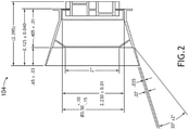
- FIG. 2 a cross-sectional view of an exemplary embodiment of the oxygen mask 104 of FIG. 1 is depicted according to the inventive concepts.
- FIG. 2 depicts exemplary suitable dimensions (e.g., in inches) and angular orientations (e.g., in degrees) of various components of the oxygen mask 104.
- FIG. 3 an isometric view of an exemplary embodiment of the oxygen mask 104 of FIG. 1 is depicted according to the inventive concepts.
- FIG. 4 an isometric view of an exemplary embodiment of the oxygen mask 104 of FIG. 1 is depicted according to the inventive concepts.
- FIG. 5 a front view of an exemplary embodiment of the oxygen mask 104 of FIG. 1 is depicted according to the inventive concepts.
- FIG. 6 a side view of an exemplary embodiment of the oxygen mask 104 of FIG. 1 is depicted according to the inventive concepts.
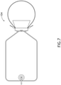
- the oxygen mask 104 may be a continuous flow oxygen mask.
- embodiments of the inventive concepts disclosed herein may be directed to a system including an oxygen mask.
- At least one means one or a plurality of; for example, “at least one” may comprise one, two, three, ..., one hundred, or more.
- one or more means one or a plurality of; for example, “one or more” may comprise one, two, three, ..., one hundred, or more.
- zero or more means zero, one, or a plurality of; for example, “zero or more” may comprise zero, one, two, three, ..., one hundred, or more.
- the methods, operations, and/or functionality disclosed may be implemented as sets of instructions or software readable by a device. Further, it is understood that the specific order or hierarchy of steps in the methods, operations, and/or functionality disclosed are examples of exemplary approaches. Based upon design preferences, it is understood that the specific order or hierarchy of steps in the methods, operations, and/or functionality can be rearranged while remaining within the scope of the inventive concepts disclosed herein.
- the accompanying claims may present elements of the various steps in a sample order, and are not necessarily meant to be limited to the specific order or hierarchy presented.
- embodiments of the methods according to the inventive concepts disclosed herein may include one or more of the steps described herein. Further, such steps may be carried out in any desired order and two or more of the steps may be carried out simultaneously with one another. Two or more of the steps disclosed herein may be combined in a single step, and in some embodiments, one or more of the steps may be carried out as two or more sub-steps. Further, other steps or sub-steps may be carried in addition to, or as substitutes to one or more of the steps disclosed herein.
Landscapes
- Health & Medical Sciences (AREA)
- Pulmonology (AREA)
- General Health & Medical Sciences (AREA)
- Business, Economics & Management (AREA)
- Emergency Management (AREA)
- Life Sciences & Earth Sciences (AREA)
- Zoology (AREA)
- Respiratory Apparatuses And Protective Means (AREA)
Abstract
Description
- Existing certified passenger oxygen masks utilized for pulse type supplemental and first-aid oxygen systems are designed to fit adults rather than infants and children. Existing certified pulse oxygen masks may be too large for infants and small children. In a civilian aviation environment, currently no oxygen mask accommodation regulation is made specifically for infants and children below the age of five.
- In one aspect, embodiments of the inventive concepts disclosed herein are directed to a system. The system may include an oxygen mask. The oxygen mask may include an oxygen supply structure. The oxygen mask may include a face seal extending away from the oxygen supply structure, wherein the face seal forms an outer opening configured to seal around a first portion of a first face of a first user of the oxygen mask, wherein a channel is formed by the face seal between the outer opening and the oxygen supply structure. The oxygen mask may include a lip seal positioned within the channel and positioned between the outer opening and the oxygen supply structure, wherein the lip seal forms a second opening configured to seal around a second portion of a second face of a second user of the oxygen mask, wherein the second opening is smaller than the outer opening, wherein the second face is smaller than the first face.
- In a further aspect, embodiments of the inventive concepts disclosed herein are directed to an oxygen mask. The oxygen mask may include an oxygen supply structure. The oxygen mask may include a face seal extending away from the oxygen supply structure, wherein the face seal forms an outer opening configured to seal around a first portion of a first face of a first user of the oxygen mask, wherein a channel is formed by the face seal between the outer opening and the oxygen supply structure. The oxygen mask may include a lip seal positioned within the channel and positioned between the outer opening and the oxygen supply structure, wherein the lip seal forms a second opening configured to seal around a second portion of a second face of a second user of the oxygen mask, wherein the second opening is smaller than the outer opening, wherein the second face is smaller than the first face.
- Implementations of the inventive concepts disclosed herein may be better understood when consideration is given to the following detailed description thereof. Such description makes reference to the included drawings, which are not necessarily to scale, and in which some features may be exaggerated and some features may be omitted or may be represented schematically in the interest of clarity. Like reference numerals in the drawings may represent and refer to the same or similar element, feature, or function. In the drawings:
-
FIG. 1 a cross-sectional view of an exemplary embodiment of a system including a vehicle including an oxygen mask according to the inventive concepts disclosed herein. -
FIG. 2 is a cross-sectional view of an exemplary embodiment of the oxygen mask ofFIG. 1 according to the inventive concepts disclosed herein. -
FIG. 3 is an isometric view of an exemplary embodiment of the oxygen mask ofFIG. 1 according to the inventive concepts disclosed herein. -
FIG. 4 is an isometric view of an exemplary embodiment of the oxygen mask ofFIG. 1 according to the inventive concepts disclosed herein. -
FIG. 5 is a front view of an exemplary embodiment of the oxygen mask ofFIG. 1 according to the inventive concepts disclosed herein. -
FIG. 6 is a side view of an exemplary embodiment of the oxygen mask ofFIG. 1 according to the inventive concepts disclosed herein. -
FIG. 7 is a view of an exemplary embodiment of the oxygen mask ofFIG. 1 according to the inventive concepts disclosed herein. - Before explaining at least one embodiment of the inventive concepts disclosed herein in detail, it is to be understood that the inventive concepts are not limited in their application to the details of construction and the arrangement of the components or steps or methodologies set forth in the following description or illustrated in the drawings. In the following detailed description of embodiments of the instant inventive concepts, numerous specific details are set forth in order to provide a more thorough understanding of the inventive concepts. However, it will be apparent to one of ordinary skill in the art having the benefit of the instant disclosure that the inventive concepts disclosed herein may be practiced without these specific details. In other instances, well-known features may not be described in detail to avoid unnecessarily complicating the instant disclosure. The inventive concepts disclosed herein are capable of other embodiments or of being practiced or carried out in various ways. Also, it is to be understood that the phraseology and terminology employed herein is for the purpose of description and should not be regarded as limiting.
- As used herein a letter following a reference numeral is intended to reference an embodiment of the feature or element that may be similar, but not necessarily identical, to a previously described element or feature bearing the same reference numeral (e.g., 1, 1a, 1b). Such shorthand notations are used for purposes of convenience only, and should not be construed to limit the inventive concepts disclosed herein in any way unless expressly stated to the contrary.
- Further, unless expressly stated to the contrary, "or" refers to an inclusive or and not to an exclusive or. For example, a condition A or B is satisfied by anyone of the following: A is true (or present) and B is false (or not present), A is false (or not present) and B is true (or present), and both A and B are true (or present).
- In addition, use of the "a" or "an" are employed to describe elements and components of embodiments of the instant inventive concepts. This is done merely for convenience and to give a general sense of the inventive concepts, and "a" and "an" are intended to include one or at least one and the singular also includes the plural unless it is obvious that it is meant otherwise.
- Finally, as used herein any reference to "one embodiment," or "some embodiments" means that a particular element, feature, structure, or characteristic described in connection with the embodiment is included in at least one embodiment of the inventive concepts disclosed herein. The appearances of the phrase "in some embodiments" in various places in the specification are not necessarily all referring to the same embodiment, and embodiments of the inventive concepts disclosed may include one or more of the features expressly described or inherently present herein, or any combination of sub-combination of two or more such features, along with any other features which may not necessarily be expressly described or inherently present in the instant disclosure.
- Broadly, embodiments of the inventive concepts disclosed herein are directed to a system including an oxygen mask. Some embodiments may include a supplemental and/or first-aid type of oxygen mask. Some embodiments may improve air travel safety by providing an oxygen mask that can accommodate adults and children (e.g., children and/or infants).
- In some embodiments, the oxygen mask may include sealing portions (e.g., a face seal and a lip seal) and an inhalation and exhalation valve suitable for use in pulse oxygen systems. The sealing portions may not significantly affect installation, deployment, or use of the oxygen system as currently certified for pulse oxygen systems, continuous flow oxygen systems, and first aid oxygen systems. For example, the lip seal may be designed to maintain a vacuum in a mask cavity during inhalation no less than that of a cracking pressure of the inhalation valve of the mask while ensuring that the system is able to sense a breath and thus deliver a pulse of oxygen. The lip seal can support a typical adult without undue discomfort or compromise of system effectiveness, and therefore, can facilitate wide scale use. In some embodiments, the oxygen mask may be used as a first aid oxygen mask and systems. In some embodiments, the oxygen mask may be a continuous flow oxygen mask.
- In some embodiments, a pulse oxygen system may deliver oxygen on-demand. When the user inhales, the system may sense a breath by measuring or sensing against vacuum conditions that result inside the mask cavity. The system may respond to inhalation by delivering a precisely metered volume (i.e., a pulse) of oxygen to the mask. As the effectiveness and efficiency of the pulse system can depend on delivering the pulse of oxygen early in the inhalation cycle, the mask can help ensure that the inhalation is detected in a reliable and timely manner.
- Existing certified pulse oxygen masks and continuous flow oxygen masks account for a certain amount of inward leakage into the mask for certain individuals; however, if the existing mask is found to be too large for an individual (e.g., too large for an infant or young child) to establish an effective seal between the mask and face, this could compromise the system such that a pulse is not delivered or the timing of such delivery may not be of an expected benefit. In some embodiments, the oxygen mask may include unique sealing portions while retaining the inhalation and exhalation valve design of existing masks. In some embodiments, the oxygen mask may have a size, shape, and function such that the mask does not significantly affect the installation, deployment, or use of the oxygen system as currently certified.
- Referring now to
FIG. 1 , a cross-sectional view of an exemplary embodiment of asystem 100 including a vehicle (e.g.,aircraft 102, watercraft, automobile, train, etc.) including at least one oxygen mask 104 (e.g., a pulse oxygen mask or a continuous flow oxygen mask) is depicted according to the inventive concepts. In some embodiments, theoxygen mask 104 may include anoxygen supply structure 106, aface seal 108, and/or alip seal 110. Theoxygen mask 104 may be configured to accommodate a user of any age (e.g., adults and children of all ages) and any size. - The
oxygen supply structure 106 may include at least one valve 118 (e.g., an inhalation and exhalation valve). In some embodiments, theoxygen supply structure 106 may be rigid, semi rigid or flexible. - The
face seal 108 may extend away from theoxygen supply structure 106. Theface seal 108 may form anouter opening 112 configured to seal around a first portion of a first face of a first user of theoxygen mask 104. Achannel 114 may be formed by theface seal 108 between theouter opening 112 and theoxygen supply structure 106. Theface seal 108 may be shaped as a first portion of a first cone surface; however, in some embodiments, theface seal 108 may have any suitable shape. In some embodiments, theouter opening 112 may be circular with a diameter of between 3 inches and 4 inches (between 7.62 centimeter (cm) and 10.16 cm); however, in some embodiments, theouter opening 112 may have any suitable shape. In some embodiments, theface seal 108 may be formed of at least one conformable flexible material (e.g., at least one thermoplastic elastomer, latex, and/or silicone). - The
lip seal 110 may be positioned within thechannel 114 and positioned between theouter opening 112 and theoxygen supply structure 106. Thelip seal 110 may form asecond opening 116 configured to seal around a second portion of a second face of a second user of theoxygen mask 104. Thesecond opening 116 may be smaller than theouter opening 112, and the second face may be smaller than the first face. Thelip seal 110 may be shaped as a second portion of a second cone surface; however, in some embodiments, thelip seal 110 may have any suitable shape. In some embodiments, thelip seal 110 may extend away from theface seal 108 at an angle between 70 and 110 degrees. In some embodiments, thesecond opening 116 may be circular with a diameter of between 1.5 inches and 2.5 inches (between 3.81 cm and 6.35 cm); however, in some embodiments, thesecond opening 116 may have any suitable shape. For example, thelip seal 110 may be conformable and flexible and positioned so as to define thesecond opening 116 appropriate for use by an infant and or child. In some embodiments, thesecond opening 116 may be of a size that if necessary, can support the breathing of a typical adult without undue discomfort or compromise of system effectiveness and therefore facilitate wide scale use with both pulse and constant flow oxygen systems. In some embodiments, thelip seal 110 may have mechanical and section characteristics so as to form a seal between the user and theoxygen mask 104. Thelip seal 110 may be designed to ensure a vacuum can be maintained in the mask cavity during inhalation that is no less than the cracking pressure of the inhalation valve of the mask. In some embodiments, thelip seal 110 may be formed of at least one conformable flexible material (e.g., at least one thermoplastic elastomer, latex, and/or silicone). In some embodiments, thelip seal 110 and theface seal 108 may be formed of a same or similar material. - In some embodiments, the
face seal 108 and thelip seal 110 are formed of an integral material. In some embodiments, theface seal 108 and thelip seal 110 may be separate components, wherein thelip seal 110 may abut an interior surface of theface seal 108. For example, thelip seal 110 may be an insert that is inserted into an existing certified oxygen mask. - Referring now to
FIG. 2 , a cross-sectional view of an exemplary embodiment of theoxygen mask 104 ofFIG. 1 is depicted according to the inventive concepts.FIG. 2 depicts exemplary suitable dimensions (e.g., in inches) and angular orientations (e.g., in degrees) of various components of theoxygen mask 104. - Referring now to
FIG. 3 , an isometric view of an exemplary embodiment of theoxygen mask 104 ofFIG. 1 is depicted according to the inventive concepts. - Referring now to
FIG. 4 , an isometric view of an exemplary embodiment of theoxygen mask 104 ofFIG. 1 is depicted according to the inventive concepts. - Referring now to
FIG. 5 , a front view of an exemplary embodiment of theoxygen mask 104 ofFIG. 1 is depicted according to the inventive concepts. - Referring now to
FIG. 6 , a side view of an exemplary embodiment of theoxygen mask 104 ofFIG. 1 is depicted according to the inventive concepts. - Referring now to
FIG. 7 , a view of an exemplary embodiment of theoxygen mask 104 ofFIG. 1 is depicted according to the inventive concepts. As shown inFIG. 7 , theoxygen mask 104 may be a continuous flow oxygen mask. - As will be appreciated from the above, embodiments of the inventive concepts disclosed herein may be directed to a system including an oxygen mask.
- As used throughout, "at least one" means one or a plurality of; for example, "at least one" may comprise one, two, three, ..., one hundred, or more. Similarly, as used throughout, "one or more" means one or a plurality of; for example, "one or more" may comprise one, two, three, ..., one hundred, or more. Further, as used throughout, "zero or more" means zero, one, or a plurality of; for example, "zero or more" may comprise zero, one, two, three, ..., one hundred, or more.
- In the present disclosure, the methods, operations, and/or functionality disclosed may be implemented as sets of instructions or software readable by a device. Further, it is understood that the specific order or hierarchy of steps in the methods, operations, and/or functionality disclosed are examples of exemplary approaches. Based upon design preferences, it is understood that the specific order or hierarchy of steps in the methods, operations, and/or functionality can be rearranged while remaining within the scope of the inventive concepts disclosed herein. The accompanying claims may present elements of the various steps in a sample order, and are not necessarily meant to be limited to the specific order or hierarchy presented.
- It is to be understood that embodiments of the methods according to the inventive concepts disclosed herein may include one or more of the steps described herein. Further, such steps may be carried out in any desired order and two or more of the steps may be carried out simultaneously with one another. Two or more of the steps disclosed herein may be combined in a single step, and in some embodiments, one or more of the steps may be carried out as two or more sub-steps. Further, other steps or sub-steps may be carried in addition to, or as substitutes to one or more of the steps disclosed herein.
- From the above description, it is clear that the inventive concepts disclosed herein are well adapted to carry out the objects and to attain the advantages mentioned herein as well as those inherent in the inventive concepts disclosed herein. While presently preferred embodiments of the inventive concepts disclosed herein have been described for purposes of this disclosure, it will be understood that numerous changes may be made which will readily suggest themselves to those skilled in the art and which are accomplished within the scope of the invention as defined by the claims.
Claims (15)
- A system, comprising:
an oxygen mask (104), comprising:an oxygen supply structure (106);a face seal (108) extending away from the oxygen supply structure, wherein the face seal forms an outer opening (112) configured to seal around a first portion of a first face of a first user of the oxygen mask, wherein a channel (114) is formed by the face seal between the outer opening and the oxygen supply structure; anda lip seal (110) positioned within the channel and positioned between the outer opening and the oxygen supply structure, wherein the lip seal forms a second opening (116) configured to seal around a second portion of a second face of a second user of the oxygen mask, wherein the second opening is smaller than the outer opening, wherein the second face is smaller than the first face. - The system of claim 1, wherein the face seal (108) is shaped as a first portion of a first cone surface, wherein the lip seal (110) is shaped as a second portion of a second cone surface.
- The system of claim 2, wherein the lip seal (110) extends away from the face seal at an angle between 70 and 110 degrees.
- The system of claim 3, wherein the second opening (116) has a diameter of between 1.5 inches and 2.5 inches (3.81 - 6.35cm), wherein the outer opening (112) has a diameter of between 3 inches and 4 inches (7.62 - 10.16cm).
- The system of claim 4, wherein the face seal (108) and the lip seal (110) are formed of a thermoplastic elastomer.
- The system of claim 5, wherein the oxygen mask is configured to accommodate a user of any age.
- The system of any preceding claim, wherein the face seal (108) and the lip seal (110) are formed of at least one conformable flexible material.
- The system of any preceding claim, wherein the face seal (108) and the lip seal (110) are formed of a thermoplastic elastomer.
- The system of any preceding claim, wherein the face seal and the lip seal are formed of an integral material.
- The system of any of claims 1 to 8, wherein the face seal (108) and the lip seal (110) are separate components, wherein the lip seal abuts an interior surface of the face seal.
- The system of any preceding claim, wherein the oxygen mask (104) is a pulse oxygen mask.
- The system of claim 11, wherein the oxygen supply structure includes a valve.
- The system of any of claims 1 to 10, wherein the oxygen mask is a continuous flow oxygen mask.
- The system of any preceding claim, further comprising an aircraft (102), the aircraft comprising the oxygen mask.
- An oxygen mask, comprisingan oxygen supply structure (106);a face seal (108) extending away from the oxygen supply structure, wherein the face seal forms an outer opening (112) configured to seal around a first portion of a first face of a first user of the oxygen mask, wherein a channel (114) is formed by the face seal between the outer opening and the oxygen supply structure; anda lip seal (110) positioned within the channel and positioned between the outer opening and the oxygen supply structure, wherein the lip seal forms a second opening (116) configured to seal around a second portion of a second face of a second user of the oxygen mask, wherein the second opening is smaller than the outer opening, wherein the second face is smaller than the first face.
Applications Claiming Priority (1)
| Application Number | Priority Date | Filing Date | Title |
|---|---|---|---|
| US17/006,069 US20220062667A1 (en) | 2020-08-28 | 2020-08-28 | Oxygen Mask And System |
Publications (1)
| Publication Number | Publication Date |
|---|---|
| EP3960248A1 true EP3960248A1 (en) | 2022-03-02 |
Family
ID=77499752
Family Applications (1)
| Application Number | Title | Priority Date | Filing Date |
|---|---|---|---|
| EP21193076.3A Withdrawn EP3960248A1 (en) | 2020-08-28 | 2021-08-25 | Oxygen mask and system |
Country Status (2)
| Country | Link |
|---|---|
| US (1) | US20220062667A1 (en) |
| EP (1) | EP3960248A1 (en) |
Citations (7)
| Publication number | Priority date | Publication date | Assignee | Title |
|---|---|---|---|---|
| US5265597A (en) * | 1992-07-01 | 1993-11-30 | Puritan-Bennett Corporation | Passenger oxygen mask having a plurality of fingers and recesses for mounting the mask to an oxygen bag |
| US20010035188A1 (en) * | 2000-04-17 | 2001-11-01 | Gleason Colin M. | Respiratory mask and service module |
| WO2006113321A2 (en) * | 2005-04-13 | 2006-10-26 | Ric Investments, Llc | Cushion inside a cushion patient interface |
| US20080230068A1 (en) * | 2007-03-19 | 2008-09-25 | Hans, Rudolph, Inc. | Ventilation mask with continuous seal connected by resilient cushion |
| WO2011077254A2 (en) * | 2009-12-23 | 2011-06-30 | Fisher & Paykel Healthcare Limited | Patient interface and headgear |
| US20180289913A1 (en) * | 2012-09-04 | 2018-10-11 | Fisher & Paykel Healthcare Limited | Valsalva mask |
| US20200230341A1 (en) * | 2011-04-15 | 2020-07-23 | Fisher & Paykel Healthcare Limited | Interface comprising a nasal sealing portion |
Family Cites Families (12)
| Publication number | Priority date | Publication date | Assignee | Title |
|---|---|---|---|---|
| US2939458A (en) * | 1957-04-29 | 1960-06-07 | Bendix Aviat Corp | Respiratory masks |
| US4414973A (en) * | 1981-03-10 | 1983-11-15 | U.S.D. Corp. | Respirator face mask |
| US4677977A (en) * | 1984-08-03 | 1987-07-07 | Gentex Corporation | Mask for pressure breathing |
| US4739755A (en) * | 1986-10-17 | 1988-04-26 | American Cyanamid Company | Respirator |
| US5408995A (en) * | 1993-04-16 | 1995-04-25 | Figgie International Inc. | Continuous flow passenger oxygen dispensing unit |
| US6412488B1 (en) * | 1999-05-12 | 2002-07-02 | Respironics, Inc. | Low contact nasal mask and system using same |
| US8851072B2 (en) * | 2007-02-16 | 2014-10-07 | Wasatch Manufacturing, Llc | Supplemental air diffusion devices, kits and methods |
| EP2144657B1 (en) * | 2007-05-02 | 2020-03-04 | RIC Investments, LLC. | Cushion for a patient interface |
| EP2219719B1 (en) * | 2007-11-15 | 2017-12-27 | ResMed Limited | A cushioning structure |
| US8539953B2 (en) * | 2008-11-19 | 2013-09-24 | John E. Moenning, Jr. | Combination anesthesia and scavenger surgical mask |
| EP3229925A2 (en) * | 2014-12-11 | 2017-10-18 | Zodiac Aerotechnics | Crystalline salts of organometallic complexes for oxygen supply in aircrafts |
| US10507298B2 (en) * | 2017-07-05 | 2019-12-17 | Orel Yehuda SWENSON | Respiration mask and seal therefor |
-
2020
- 2020-08-28 US US17/006,069 patent/US20220062667A1/en not_active Abandoned
-
2021
- 2021-08-25 EP EP21193076.3A patent/EP3960248A1/en not_active Withdrawn
Patent Citations (7)
| Publication number | Priority date | Publication date | Assignee | Title |
|---|---|---|---|---|
| US5265597A (en) * | 1992-07-01 | 1993-11-30 | Puritan-Bennett Corporation | Passenger oxygen mask having a plurality of fingers and recesses for mounting the mask to an oxygen bag |
| US20010035188A1 (en) * | 2000-04-17 | 2001-11-01 | Gleason Colin M. | Respiratory mask and service module |
| WO2006113321A2 (en) * | 2005-04-13 | 2006-10-26 | Ric Investments, Llc | Cushion inside a cushion patient interface |
| US20080230068A1 (en) * | 2007-03-19 | 2008-09-25 | Hans, Rudolph, Inc. | Ventilation mask with continuous seal connected by resilient cushion |
| WO2011077254A2 (en) * | 2009-12-23 | 2011-06-30 | Fisher & Paykel Healthcare Limited | Patient interface and headgear |
| US20200230341A1 (en) * | 2011-04-15 | 2020-07-23 | Fisher & Paykel Healthcare Limited | Interface comprising a nasal sealing portion |
| US20180289913A1 (en) * | 2012-09-04 | 2018-10-11 | Fisher & Paykel Healthcare Limited | Valsalva mask |
Also Published As
| Publication number | Publication date |
|---|---|
| US20220062667A1 (en) | 2022-03-03 |
Similar Documents
| Publication | Publication Date | Title |
|---|---|---|
| EP3082925B1 (en) | Customizable facial sealing segment for respiratory device and method of customizing | |
| EP2968820B1 (en) | Subnasal sealing cushion | |
| US6412488B1 (en) | Low contact nasal mask and system using same | |
| US5765553A (en) | Aerosol medication delivery facemask adapter | |
| EP2849828B1 (en) | Sealing cushion and patient interface device employing same | |
| US9604023B2 (en) | Respiratory mask with ribbed contacting surface | |
| US10926049B2 (en) | Patient interface device with frame and clips | |
| US8215305B2 (en) | Cushion for ventilation interface | |
| US9433741B2 (en) | Custom adjustable patient interface device | |
| US20150013685A1 (en) | Patient interface with expandable nasal prongs | |
| JP2002533174A (en) | Suffocation prevention valve | |
| US20190282839A1 (en) | System and a method for delivering breathing gas to passengers on-board an aircraft | |
| US20170333658A1 (en) | Headgear tubing assembly and integrated pressure sensing | |
| EP2552525B1 (en) | Exhaust valve and method of manufacture therefore | |
| EP2903675B1 (en) | Customizable cushion utilizing fitted plug inserts | |
| US20160263339A1 (en) | Convertible patient interface device | |
| US20110297158A1 (en) | Cpap mask frame | |
| US20220096768A1 (en) | Exhaust arrangement for patient interface device and patient interface including same | |
| US20220062667A1 (en) | Oxygen Mask And System | |
| US3467093A (en) | Oxygen mask and valve structure | |
| CA2646361A1 (en) | Supplemental passenger oxygen mask | |
| US20140305438A1 (en) | Patient interface device with cushion sealing arrangement | |
| EP3174587B1 (en) | Fluid coupling conduit for a patient interface device |
Legal Events
| Date | Code | Title | Description |
|---|---|---|---|
| PUAI | Public reference made under article 153(3) epc to a published international application that has entered the european phase |
Free format text: ORIGINAL CODE: 0009012 |
|
| STAA | Information on the status of an ep patent application or granted ep patent |
Free format text: STATUS: THE APPLICATION HAS BEEN PUBLISHED |
|
| AK | Designated contracting states |
Kind code of ref document: A1 Designated state(s): AL AT BE BG CH CY CZ DE DK EE ES FI FR GB GR HR HU IE IS IT LI LT LU LV MC MK MT NL NO PL PT RO RS SE SI SK SM TR |
|
| STAA | Information on the status of an ep patent application or granted ep patent |
Free format text: STATUS: REQUEST FOR EXAMINATION WAS MADE |
|
| 17P | Request for examination filed |
Effective date: 20220902 |
|
| RBV | Designated contracting states (corrected) |
Designated state(s): AL AT BE BG CH CY CZ DE DK EE ES FI FR GB GR HR HU IE IS IT LI LT LU LV MC MK MT NL NO PL PT RO RS SE SI SK SM TR |
|
| P01 | Opt-out of the competence of the unified patent court (upc) registered |
Effective date: 20230922 |
|
| STAA | Information on the status of an ep patent application or granted ep patent |
Free format text: STATUS: EXAMINATION IS IN PROGRESS |
|
| 17Q | First examination report despatched |
Effective date: 20240912 |
|
| STAA | Information on the status of an ep patent application or granted ep patent |
Free format text: STATUS: THE APPLICATION IS DEEMED TO BE WITHDRAWN |
|
| 18D | Application deemed to be withdrawn |
Effective date: 20250114 |