EP3960140A1 - Composite stretchable member manufacturing apparatus - Google Patents
Composite stretchable member manufacturing apparatus Download PDFInfo
- Publication number
- EP3960140A1 EP3960140A1 EP20805033.6A EP20805033A EP3960140A1 EP 3960140 A1 EP3960140 A1 EP 3960140A1 EP 20805033 A EP20805033 A EP 20805033A EP 3960140 A1 EP3960140 A1 EP 3960140A1
- Authority
- EP
- European Patent Office
- Prior art keywords
- guide
- sheets
- conveying roller
- elastic members
- elastic member
- Prior art date
- Legal status (The legal status is an assumption and is not a legal conclusion. Google has not performed a legal analysis and makes no representation as to the accuracy of the status listed.)
- Granted
Links
Images








Classifications
-
- A—HUMAN NECESSITIES
- A61—MEDICAL OR VETERINARY SCIENCE; HYGIENE
- A61F—FILTERS IMPLANTABLE INTO BLOOD VESSELS; PROSTHESES; DEVICES PROVIDING PATENCY TO, OR PREVENTING COLLAPSING OF, TUBULAR STRUCTURES OF THE BODY, e.g. STENTS; ORTHOPAEDIC, NURSING OR CONTRACEPTIVE DEVICES; FOMENTATION; TREATMENT OR PROTECTION OF EYES OR EARS; BANDAGES, DRESSINGS OR ABSORBENT PADS; FIRST-AID KITS
- A61F13/00—Bandages or dressings; Absorbent pads
- A61F13/15—Absorbent pads, e.g. sanitary towels, swabs or tampons for external or internal application to the body; Supporting or fastening means therefor; Tampon applicators
- A61F13/15577—Apparatus or processes for manufacturing
- A61F13/15585—Apparatus or processes for manufacturing of babies' napkins, e.g. diapers
- A61F13/15593—Apparatus or processes for manufacturing of babies' napkins, e.g. diapers having elastic ribbons fixed thereto; Devices for applying the ribbons
-
- A—HUMAN NECESSITIES
- A61—MEDICAL OR VETERINARY SCIENCE; HYGIENE
- A61F—FILTERS IMPLANTABLE INTO BLOOD VESSELS; PROSTHESES; DEVICES PROVIDING PATENCY TO, OR PREVENTING COLLAPSING OF, TUBULAR STRUCTURES OF THE BODY, e.g. STENTS; ORTHOPAEDIC, NURSING OR CONTRACEPTIVE DEVICES; FOMENTATION; TREATMENT OR PROTECTION OF EYES OR EARS; BANDAGES, DRESSINGS OR ABSORBENT PADS; FIRST-AID KITS
- A61F13/00—Bandages or dressings; Absorbent pads
- A61F13/15—Absorbent pads, e.g. sanitary towels, swabs or tampons for external or internal application to the body; Supporting or fastening means therefor; Tampon applicators
- A61F13/45—Absorbent pads, e.g. sanitary towels, swabs or tampons for external or internal application to the body; Supporting or fastening means therefor; Tampon applicators characterised by the shape
- A61F13/49—Absorbent pads, e.g. sanitary towels, swabs or tampons for external or internal application to the body; Supporting or fastening means therefor; Tampon applicators characterised by the shape specially adapted to be worn around the waist, e.g. diapers, nappies
- A61F13/49007—Form-fitting, self-adjusting disposable diapers
- A61F13/49009—Form-fitting, self-adjusting disposable diapers with elastic means
- A61F13/49011—Form-fitting, self-adjusting disposable diapers with elastic means the elastic means is located at the waist region
-
- A—HUMAN NECESSITIES
- A61—MEDICAL OR VETERINARY SCIENCE; HYGIENE
- A61F—FILTERS IMPLANTABLE INTO BLOOD VESSELS; PROSTHESES; DEVICES PROVIDING PATENCY TO, OR PREVENTING COLLAPSING OF, TUBULAR STRUCTURES OF THE BODY, e.g. STENTS; ORTHOPAEDIC, NURSING OR CONTRACEPTIVE DEVICES; FOMENTATION; TREATMENT OR PROTECTION OF EYES OR EARS; BANDAGES, DRESSINGS OR ABSORBENT PADS; FIRST-AID KITS
- A61F13/00—Bandages or dressings; Absorbent pads
- A61F13/15—Absorbent pads, e.g. sanitary towels, swabs or tampons for external or internal application to the body; Supporting or fastening means therefor; Tampon applicators
- A61F13/15577—Apparatus or processes for manufacturing
- A61F13/15699—Forming webs by bringing together several webs, e.g. by laminating or folding several webs, with or without additional treatment of the webs
-
- A—HUMAN NECESSITIES
- A61—MEDICAL OR VETERINARY SCIENCE; HYGIENE
- A61F—FILTERS IMPLANTABLE INTO BLOOD VESSELS; PROSTHESES; DEVICES PROVIDING PATENCY TO, OR PREVENTING COLLAPSING OF, TUBULAR STRUCTURES OF THE BODY, e.g. STENTS; ORTHOPAEDIC, NURSING OR CONTRACEPTIVE DEVICES; FOMENTATION; TREATMENT OR PROTECTION OF EYES OR EARS; BANDAGES, DRESSINGS OR ABSORBENT PADS; FIRST-AID KITS
- A61F13/00—Bandages or dressings; Absorbent pads
- A61F13/15—Absorbent pads, e.g. sanitary towels, swabs or tampons for external or internal application to the body; Supporting or fastening means therefor; Tampon applicators
- A61F13/45—Absorbent pads, e.g. sanitary towels, swabs or tampons for external or internal application to the body; Supporting or fastening means therefor; Tampon applicators characterised by the shape
- A61F13/49—Absorbent pads, e.g. sanitary towels, swabs or tampons for external or internal application to the body; Supporting or fastening means therefor; Tampon applicators characterised by the shape specially adapted to be worn around the waist, e.g. diapers, nappies
- A61F13/49007—Form-fitting, self-adjusting disposable diapers
- A61F13/49009—Form-fitting, self-adjusting disposable diapers with elastic means
- A61F13/4902—Form-fitting, self-adjusting disposable diapers with elastic means characterised by the elastic material
-
- B—PERFORMING OPERATIONS; TRANSPORTING
- B29—WORKING OF PLASTICS; WORKING OF SUBSTANCES IN A PLASTIC STATE IN GENERAL
- B29C—SHAPING OR JOINING OF PLASTICS; SHAPING OF MATERIAL IN A PLASTIC STATE, NOT OTHERWISE PROVIDED FOR; AFTER-TREATMENT OF THE SHAPED PRODUCTS, e.g. REPAIRING
- B29C66/00—General aspects of processes or apparatus for joining preformed parts
- B29C66/01—General aspects dealing with the joint area or with the area to be joined
- B29C66/05—Particular design of joint configurations
- B29C66/10—Particular design of joint configurations particular design of the joint cross-sections
- B29C66/11—Joint cross-sections comprising a single joint-segment, i.e. one of the parts to be joined comprising a single joint-segment in the joint cross-section
- B29C66/112—Single lapped joints
- B29C66/1122—Single lap to lap joints, i.e. overlap joints
-
- B—PERFORMING OPERATIONS; TRANSPORTING
- B29—WORKING OF PLASTICS; WORKING OF SUBSTANCES IN A PLASTIC STATE IN GENERAL
- B29L—INDEXING SCHEME ASSOCIATED WITH SUBCLASS B29C, RELATING TO PARTICULAR ARTICLES
- B29L2031/00—Other particular articles
- B29L2031/48—Wearing apparel
- B29L2031/4871—Underwear
- B29L2031/4878—Diapers, napkins
Definitions
- the present invention relates to a manufacturing apparatus for manufacturing a composite stretchable member.
- Wearing articles such as a disposable diaper having a waistline portion and a crotch portion have been known.
- the waistline portion of the wearing article may be formed of a composite stretchable member, which is stretchable, to improve wearing comfort.
- Patent Literature 1 As an apparatus for manufacturing a composite stretchable member, for example, an apparatus described in Patent Literature 1 is known.
- Patent Literature 1 performs welding processing with an elastically stretchable member sandwiched between two sheets made of a nonwoven fabric or the like by feeding these two sheets and the elastically stretchable member to a nip between an ultrasonic welding horn and an anvil roll for conveying sheets.
- the anvil roll is provided on its outer periphery with a seal pattern protruding section, and a welding portion is formed on each of the two sheets corresponding to the seal pattern protruding section.
- the seal pattern protruding section is provided with a groove formed corresponding to a portion where the elastically stretchable member is disposed.
- the groove has a depth that is set to cause a part of the elastically stretchable member to protrude from the groove when the elastically stretchable member is inserted into the groove.
- Inserting a part of the elastically stretchable member into the groove reduces pressure for sandwiching the elastically stretchable member when the two sheets and the elastically stretchable member are ultrasonically welded while being sandwiched between the ultrasonic welding horn and the seal pattern protruding section of the anvil roll. This enables the two sheets and the elastically stretchable member to be welded without cutting the elastically stretchable member.
- Patent Literature 1 is provided with a guide member upstream of the anvil roll in a direction of supplying the elastically stretchable member to the anvil roll.
- the guide member is disposed away from an outer peripheral surface of the anvil roll, and guides the elastically stretchable member into the groove of the seal pattern protruding section on the anvil roll.
- Patent Literature 1 is configured to guide the elastically stretchable member into the groove of the seal pattern protruding section on the anvil roll using the guide member, and the elastically stretchable member may be detached from the groove due to influence of vibration of the apparatus or the like. This requires to improve a function of preventing cutting by reducing a defect in which the elastically stretchable member is detached from the groove.
- Patent Literature 1 International Publication WO 2016/208502 A
- a manufacturing apparatus for manufacturing a composite stretchable member is configured to bond two sheets to each other and bond the sheets to multiple elastic members while conveying each of the sheets in a longitudinal direction to manufacture a composite stretchable member including the two sheets, and the multiple elastic members sandwiched between the two sheets
- the manufacturing apparatus for manufacturing a composite stretchable member including: a bonding device that welds and bonds the multiple elastic members to the two sheets, and the two sheets to each other, while the multiple elastic members are sandwiched between the two sheets being conveyed; and a guide device that guides the two sheets and the multiple elastic members to the bonding device in such a manner that each of the multiple elastic members extends in a longitudinal direction thereof and is sandwiched between the two sheets
- the bonding device having: a conveying roller that has an outer peripheral surface used for conveying the two sheets sandwiching the multiple elastic members in the longitudinal direction of each of the two sheets and that rotates about an axis predetermined; and a compressing device that faces the outer peripheral surface of the convey
- FIG. 1 is a plan view of a composite stretchable member manufactured by a manufacturing apparatus according to an embodiment of the present invention.
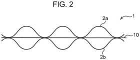
- FIG. 2 is a part of a sectional view taken along line II-II in FIG. 1 .
- a composite stretchable member 1 includes two elongated sheets 2a, 2b facing each other, and multiple elongated elastic members 10 stretchable in a longitudinal direction A.
- Each of the elastic members 10 is disposed between the sheets 2a, 2b so as to be stretchable in the longitudinal direction A (the left-right direction in FIG. 1 ) of each of the sheets 2a, 2b, i.e., so as to extend and contract in the longitudinal direction A of each of the sheets 2a, 2b along the longitudinal direction A.
- the elastic members 10 are disposed at equal intervals in a width direction B (a direction orthogonal to the longitudinal direction A of the sheets 2a, 2b) of the sheets 2a, 2b, and extend parallel to the longitudinal direction A of the sheets 2a, 2b.
- a sheet-like material such as a nonwoven fabric is used as the sheets 2a, 2b.
- An elastic member 10 is made of a material that is more elastic than the material (nonwoven fabric or the like) of the sheets 2a, 2b, and the material of the elastic member 10 is not particularly limited in the present invention.
- the elastic member 10 is a multi-strand provided with multiple rubber threads (fibrous elastic bodies) 10a collected in a bundle, and includes at least some of the rubber threads 10a each having the periphery covered with a covering layer 10b, for example.
- the rubber threads 10a disposed particularly in an outer peripheral portion among the multiple rubber threads 10a are each covered with the covering layer 10b. Every rubber thread 10a may be covered with the covering layer 10b.
- Examples of the material of the rubber thread 10a include polyurethane.
- Examples of the material of the covering layer 10b include a lubricant such as silicon oil or magnesium stearate.
- FIG. 1 illustrates a bonding section 4 in a lattice shape on which the sheets 2a, 2b are bonded to each other, and the sheets 2a, 2b are bonded to the elastic members 10.
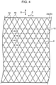
- FIG. 4 schematically illustrates the bonding section of FIG. 1 .
- the bonding section 4 includes multiple first bonding portions 4a and multiple second bonding portions 4b.
- the first bonding portions 4a are disposed at equal intervals in the longitudinal direction A of the sheets 2a, 2b, and extend parallel to each other in the width direction B of the sheets 2a, 2b.
- the second bonding portions 4b are also disposed at equal intervals in the longitudinal direction A of the sheets 2a, 2b, and extend parallel to each other in the width direction B of the sheets 2a, 2b.
- the second bonding portions 4b extend intersecting the corresponding first bonding portions 4a, thereby forming the bonding section 4 in a lattice shape.
- both a first bonding portion 4a and a second bonding portion 4b are inclined with respect to the width direction B of the sheets 2a, 2b.
- the inclination angle is smaller than 45 degrees.
- the inclination angle is set to 30 degrees.
- the first bonding portion 4a and the second bonding portion 4b each have a symmetrical shape with respect to both straight lines extending in the longitudinal direction A and the width direction B of the sheets 2a, 2b.
- the first bonding portions 4a and the second bonding portions 4b are disposed such that a clearance between two adjacent first bonding portions 4a is equal to a clearance between two adjacent second bonding portions 4b. This causes the bonding section 4 to have multiple defined rhombuses each having diagonals extend along the longitudinal direction A and the width direction B of the sheets 2a, 2b.
- first bonding portion 4a and the second bonding portion 4b are each inclined with respect to the width direction B of the sheets 2a, 2b at an angle smaller than 45 degrees, and thus the first bonding portion 4a and the second bonding portion 4b form a rhombus extending in the width direction B.
- Intersections 4c between the first bonding portions 4a and the corresponding second bonding portions 4b which may be referred to below as bonding-portion side intersections, are arranged at equal intervals on a straight line extending in the longitudinal direction A of the sheets 2a, 2b, and are arranged at equal intervals on a straight line extending in the width direction B of the sheets 2a, 2b.
- Each bonding section 4 intersects all the elastic members 10 and extends along a line intersecting an extending direction (i.e., the longitudinal direction A) of the elastic members 10. Specifically, each bonding section 4 extends between opposite outer portions of the sheets 2a, 2b in the width direction B across a region where the elastic members 10 are disposed.
- Each of the elastic members 10 and the bonding section 4 intersect at a portion excluding the bonding-portion side intersection 4c, i.e., at a position away from the bonding-portion side intersection 4c, and each of the elastic members 10 is bonded to the sheets 2a, 2b at this position.
- FIG. 5 is an enlarged view of a part of FIG. 1 , the configuration will be specifically described.
- Each elastic member 10 is disposed passing through between two adjacent bonding-portion side intersections 4c on each first bonding portion 4a (e.g., between a bonding-portion side intersection 4c_1 and a bonding-portion side intersection 4c_2, and between a bonding-portion side intersection 4c_2 and a bonding-portion side intersection 4c_3 illustrated in FIG. 5 ). That is, a first elastic-member side intersection 4d, which is an intersection between each elastic member 10 and the corresponding one of the first bonding portions 4a, is positioned between two adjacent bonding-portion side intersections 4c on the first bonding portion 4a, and the elastic member 10 is bonded to the sheets 2a, 2b at this position 4d.
- each elastic member 10 is disposed passing through between adjacent bonding-portion side intersections 4c on each second bonding portion 4b (e.g., between a bonding-portion side intersection 4c_4 and a bonding-portion side intersection 4c_2, and between a bonding-portion side intersection 4c_2 and a bonding-portion side intersection 4c_5 illustrated in FIG. 5 ). That is, a second elastic-member side intersection 4e, which is an intersection between each elastic member 10 and the corresponding one of the second bonding portions 4b, is positioned between two adjacent bonding-portion side intersections 4c on the second bonding portion 4b, and the elastic member 10 is bonded to the sheets 2a, 2b at this position 4e.
- each elastic member 10 passes through the center of the adjacent bonding-portion side intersections 4c and 4c on each first bonding portion 4a, and the center of the adjacent bonding-portion side intersections 4c and 4c on each second bonding portion 4b, and intersects the first bonding portion 4a and the second bonding portion 4b at the center position to be bonded to the sheets 2a, 2b.
- first elastic-member side intersection 4d and the second elastic-member side intersection 4e are alternately arranged on a straight line extending in the width direction B of both the sheets 2a, 2b.
- Intersections between the respective elastic members 10 and the bonding section 4, i.e., bonding points 4d and 4e between the elastic members 10 and the sheets 2a, 2b are disposed at equal intervals in the longitudinal direction A of the sheets 2a, 2b.
- the sheets 2a, 2b as well as the sheets 2a, 2b and the elastic member 10 are bonded to each other by welding. In the present embodiment, these are ultrasonically welded.
- the sheets 2a, 2b are bonded to each other by being partially melted and welded.
- the elastic member 10 and the sheets 2a, 2b are welded to each other when the sheets 2a, 2b are partially melted and the covering layer 10b of the elastic member 10 is melted.
- a rubber thread having a melting point of about 200°C is used as the rubber thread 10a
- the covering layer 10b is made of magnesium stearate (melting point: about 120°C) having a lower melting point than the rubber thread.
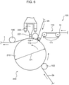
- FIG. 6 is a schematic view of a manufacturing apparatus 100 according to an embodiment of the present invention.
- the manufacturing apparatus 100 includes: a bonding device 200 that ultrasonically welds and bonds the elastic member 10 to the sheets 2a, 2b, and the sheets 2a, 2b to each other while the elastic member 10 is sandwiched between the sheets 2a, 2b; a first guide roller 102 that guides the sheet 2a to the bonding device 200 (specifically, an anvil roll 210 described later); an elastic member guide device (guide device) 110 that supplies the elastic member 10 to the bonding device 200; a nip roll (second guide roller) 104 that guides the sheet 2b to the bonding device 200 and presses the two sheets 2a, 2b, and the elastic member 10; and a third guide roller 106 that guides a bonded sheet or the like, i.e., the composite stretchable member 1.
- a bonding device 200 that ultrasonically welds and bonds the elastic member 10 to the sheets 2a, 2b, and the sheets 2a, 2b to each other while the elastic member 10 is sandwiched between the sheets 2a, 2b
- the bonding device 200 includes the anvil roll (conveying roller) 210 and a horn (compressing device) 220.
- the anvil roll 210 is a rotating member that rotates about an axis extending in a direction orthogonal to the paper surface of FIG. 6 .
- the direction orthogonal to the paper surface of FIG. 6 is referred to as a "front-back direction".
- the anvil roll 210 is rotatably attached to a rotation shaft, as a rotation center, extending horizontally with respect to a vertical wall portion of an apparatus, such as a panel (not illustrated).
- the anvil roll 210 rotates to convey the elastic member 10 guided by the elastic member guide device 110 while the elastic member 10 is sandwiched between the sheets 2a, 2b guided by the rollers 102 and 104, respectively, on the outer peripheral surface of the anvil roll 210.
- the anvil roll 210 rotates counterclockwise in FIG. 6 .
- the sheets 2a, 2b sandwiching the elastic member 10 may be referred to as pre-bonding sheets.
- the outer peripheral surface of the anvil roll 210 is provided with a protruding section 212 protruding radially outward.
- the protruding section 212 is provided on the outer peripheral surface of the anvil roll 210 throughout the outer peripheral surface in its circumferential direction.
- the protruding section 212 has a shape corresponding to that of the bonding section 4.
- the bonding section 4 has a rhombic lattice shape as described above, and the protruding section 212 has a rhombic lattice shape correspondingly.
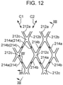
- the protruding section 212 includes first protruding portions 212a for forming the first bonding portions 4a and second protruding portions 212b for forming the second bonding portions 4b.
- the first protruding portions 212a extend along a direction (first direction C1) intersecting the circumferential direction of the anvil roll 210 (conveying direction of the anvil roll 210), i.e., along a line intersecting the circumferential direction, and are disposed parallel to each other at equal intervals in the circumferential direction.
- the second protruding portions 212b extend along a direction (second direction C2) intersecting the circumferential direction of the anvil roll 210 and the first direction C1, i.e., along a line intersecting the circumferential direction, and are disposed parallel to each other at equal intervals in the circumferential direction of the anvil roll 210.
- the first protruding portions 212a and the second protruding portions 212b are each symmetrically inclined at an angle smaller than 45 degrees with respect to the front-back direction, and are provided such that a clearance between two adjacent first protruding portions 212a is equal to a clearance between two adjacent second protruding portions 212b, and intersections 212c of the first protruding portions 212a and the corresponding second protruding portions 212b are arranged at equal intervals on a line extending in the front-back direction and the circumferential direction of the anvil roll 210.
- the first protruding portion 212a and the second protruding portion 212b are each provided with a groove 214 (214a or 214b) recessed inward in a radial direction of the anvil roll 210.
- the first protruding portions 212a and the second protruding portions 212b are each provided with multiple grooves 214 at respective positions away from each other in the longitudinal directions C1 and C2 thereof.
- the first protruding portions 212a are each provided with the grooves (first grooves) 214a extending in the circumferential direction of the anvil roll 210, being each formed in a portion between intersections 212c with the corresponding second protruding portions 212b, more specifically, in a central portion of adjacent intersections 212c.
- the second protruding portions 212b are each provided with the grooves (second grooves) 214b that are each formed in a portion between intersections 212c with the corresponding first protruding portions 212a, more specifically, in a central portion of adjacent intersections 212c.
- These grooves 214 are provided at equal intervals on a line extending along the circumferential direction of the anvil roll 210, and are provided at equal intervals on a straight line extending along the front-back direction (i.e., a direction parallel to the rotation shaft of the anvil roll 210, in other words, the same direction as the extending direction of the rotation shaft).
- the sheet 2a is conveyed by the anvil roll 210 while having a portion where the elastic member 10 is disposed, the portion being inserted into the corresponding grooves 214.
- the elastic members 10 are guided into the corresponding grooves 214 by a guide plate 112 provided with guide grooves 114b at positions corresponding to the respective grooves 214, so that the elastic members 10 are each stably disposed at an appropriate position on the sheet 2a.
- the sheet 2a together with the elastic members 10 that are partially inserted into the corresponding grooves 214 are conveyed by the anvil roll 210. Only the sheet 2a with portions inserted into the grooves may be conveyed.
- the grooves 214 are formed in the protruding section 212 at portions where the respective elastic members 10 are disposed as described above, so that at least a part of each of the elastic members 10 disposed on a pre-bonding sheet is retracted in the corresponding grooves when the pre-bonding sheet is compressed during bonding. Thus, an elastic member 10 is prevented from being cut when being compressed.
- the elastic member 10 may be less likely to be appropriately bonded to the sheets 2a, 2b.
- the elastic member 10 with a natural length is disposed in the groove 214, a part of the elastic member 10 protrudes outward from the groove 214, and the rest of the elastic member 10 is accommodated in the groove 214.
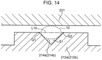
- the groove 214 is configured to have a section taken along a plane orthogonal to the circumferential direction (conveying direction) of the anvil roll 210, the section having a shape in which when the elastic member 10 is disposed in the groove 214 with the natural length, a part of the elastic member 10 protrudes outward in the radial direction of the anvil roll 210 from a linear imaginary line L10 connecting open ends (Q1, Q2) of the groove 214.
- the groove 214 is also configured to have the sectional shape in which when the elastic member 10 is extended from a natural state (e.g., when being elongated 300%) is disposed in the groove 214, a part of the elastic member 10 protrudes outward in the radial direction of the anvil roll 210 from the linear imaginary line L10 connecting the open ends (Q1, Q2) of the groove 214.
- the groove 214 described above preferably has a sectional shape of a substantially V-shape as illustrated in FIG. 14 .
- the groove 214 described above preferably has a sectional area S1 smaller than a sectional area of the elastic member 10 to be disposed.
- the sectional shape of the groove 214 is not limited to a V-shape, and may be another shape such as a U-shape.
- the elastic member 10 disposed in the groove and the sheets 2a, 2b can be appropriately compressed and bonded to each other during ultrasonic welding while the elastic member 10 is retracted into the groove 214.
- the sheets 2a, 2b and the elastic members 10 can be more reliably bonded to each other while the elastic members 10 is prevented from being damaged.
- a portion of the elastic member 10 inside the imaginary line L10 i.e., the portion accommodated in the groove 214, can be retracted inside the groove 214 (a side away from the horn 220) while pressure is appropriately applied to a portion of the elastic member 10, protruding outside the imaginary line L10 connecting the open ends Q1 and Q2 of the groove 214, and the sheets 2a, 2b.
- This enables preventing the elastic member 10 from being damaged while securing bonding force between the elastic member 10 and the sheets 2a, 2b.
- the sectional shape of the groove 214 is set such that the elastic member 10 partially protrudes outward in the radial direction of the anvil roll 210 from the linear imaginary line L10 connecting the open ends (Q1, Q2) of the groove 214 when the elastic member 10 elongated 300% is disposed in the groove 214, the sheets 2a, 2b and the elastic member 10 can be more reliably bonded to each other by being appropriately subjected to pressure while the elastic member 10 is prevented from being damaged.
- the horn 220 illustrated in FIGS. 6 and 10A is a device that applies ultrasonic vibration to a pre-bonding sheet conveyed by the anvil roll 210 while compressing (pressurizing while sandwiching) the pre-bonding sheet with the outer peripheral surface of the anvil roll 210.
- the horn 220 is disposed to face the outer peripheral surface of the anvil roll 210.
- the horn 220 is disposed to face an upper portion of the outer peripheral surface of the anvil roll 210.
- the horn 220 is provided at its leading end with an output unit 221 that applies ultrasonic vibration toward the outer peripheral surface of the anvil roll 210.
- the horn 220 applies ultrasonic vibration to a pre-bonding sheet with the output unit 221 pressing against the pre-bonding sheet and compressing the pre-bonding sheet together with the anvil roll 210. This causes the sheets 2a, 2b to be melted and welded to each other. The elastic member 10 is also melted, so that the elastic member 10 and the sheets 2a, 2b are welded to each other. Specifically, the output unit 221 compresses the pre-bonding sheet together with the protruding section 212, and bonds the sheets 2a, 2b to each other and bonds the elastic member 10 to the sheets 2a, 2b in a portion of the pre-bonding sheet disposed on the protruding section 212.
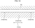
- the leading end of the output unit 221 has a planar shape (See FIGS. 13 and 14 ).
- the covering layer 10b is made of magnesium stearate having a lower melting point than the rubber thread 10a.
- the covering layer 10b is melted to weld the covering layer 10b to the sheets 2a, 2b without melting of the rubber thread 10a.
- the output unit 221 at the leading end of the horn 220 extends in the front-back direction, and the horn 220 applies ultrasonic vibration to the outer peripheral surface of the anvil roll 210 throughout in a rotation axis direction of the anvil roll 210. While a pre-bonding sheet is conveyed by the anvil roll 210, the horn 220 always applies ultrasonic vibration. Thus, as the pre-bonding sheet is conveyed by the anvil roll 210, the pre-bonding sheet is continuously bonded.
- the sheet 2a is guided by the first guide roller 102 to a position separated upstream from the horn 220 on the outer peripheral surface of the anvil roll 210.
- the sheet 2a is conveyed toward the horn 220 along the outer peripheral surface of the anvil roll 210 along with rotation of the anvil roll 210.
- the sheet 2b is introduced into a portion of the outer peripheral surface of the anvil roll 210, being near the horn 220 and upstream of the horn 220 in the conveying direction, by the nip roll 104.
- the elastic member 10 is introduced onto the outer peripheral surface of the anvil roll 210 at a position between a position where the sheet 2a is introduced onto the anvil roll 210 and a position where the sheet 2b is introduced onto the anvil roll 210 by the elastic member guide device 110. As a result, the elastic member 10 is conveyed to a position facing the horn 220 while being sandwiched between the sheets 2a, 2b.
- the sheet 2b may be introduced onto the anvil roll 210 from the nip roll 104 at any position between a position where the elastic member 10 is introduced and a position facing the horn 220, the position is preferably on a side close to the position facing the horn 220, and more preferably near the position facing the horn 220.
- the nip roll 104 is disposed at a position closest upstream of the horn 220 in the conveying direction of the sheets 2a, 2b, i.e., the rotation direction of the anvil roll 210 (counterclockwise direction in FIG. 10A ). This configuration enables preventing the elastic member 10 introduced onto the outer peripheral surface of the anvil roll 210 from being covered with the sheet 2b at an early stage and from causing positional deviation.
- the elastic members 10 are introduced onto the outer peripheral surface of the anvil roll 210 while being arranged parallel to each other in the front-back direction, and are placed on the sheet 2a, which is previously introduced onto the outer peripheral surface of the anvil roll 210, parallel to each other in the width direction B, on the outer peripheral surface of the anvil roll 210.
- the elastic members 10 are each introduced onto the anvil roll 210 while being elongated in the circumferential direction of the anvil roll 210.
- the elastic members 10 are each introduced onto the anvil roll 210 while being elongated 300% of the natural state when the natural state is set to 100%.
- the elastic member guide device 110 (in particular, the guide plate 112) of the present embodiment will be described in detail.
- the elastic member guide device 110 includes multiple guide rolls 111 and a guide plate 112 in a plate-like shape as a guide member.
- Each of the guide rolls 111 is a rotary member rotatable about its axis extending in the front-back direction, and guides the elastic member 10 toward the anvil roll 210 while the elastic member 10 is elongated (e.g., elongated 300%).
- the guide plate 112 is a tabular member that guides the elastic members 10 to the corresponding grooves 214 (see FIG. 11 to 14 ) formed on the outer peripheral surface of the anvil roll 210 while the elastic members 10 are separated from each other in the front-back direction, i.e., in a direction parallel to the axis of the anvil roll 210.
- the guide plate 112 has a leading end 114a, which is an edge closest to the outer peripheral surface of the anvil roll 210, and a proximal end disposed farther away from the anvil roll 210 than the leading end 114a.
- the guide plate 112 is disposed to extend not only in a direction of coming into contact with and separating from the anvil roll 210 but also in the front-back direction.
- the guide plate 112 has a thickness t (dimension in a vertical direction illustrated in FIG. 8 ) that is set to be small, and has a thin plate shape.
- the leading end 114a of the guide plate 112 has a tapered shape.
- the guide plate 112 is provided in its leading end portion (portion close to the anvil roll 210) with an inclined surface 114c that is inclined toward the leading end 114a to approach a bottom surface 114d of the guide plate 112.
- the inclined surface 114c and the bottom surface 114d form the leading end 114a tapered.
- the inclined surface 114c and the bottom surface 114d form an angle ⁇ 2 that is set to about 10 degrees.
- the leading end 114a of the guide plate 112 is disposed upstream (right side in FIG. 10 ) of a contact point P2 at which the guide plate 112 is in contact with the elastic member 10 on the outer peripheral surface of the anvil roll 210 in the rotation direction (counterclockwise direction in FIG. 10 ) of the anvil roll 210 while facing upstream.
- the guide plate 112 is fixed in a stationary manner at a predetermined position facing the outer peripheral surface of the anvil roll 210.
- the guide plate 112 is fixed to a fixing member 113, which is fixed to a panel or the like inside the apparatus, by screwing or the like to be prevented from being displaced.
- the leading end 114a tapered of the guide plate 112 is provided with multiple guide grooves 114b.
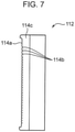
- the guide grooves 114b are formed at respective positions away from each other at equal intervals in the front-back direction (direction parallel to the axis of the anvil roll 210) at the leading end 114a of the guide plate 112, and individually hold the respective elastic members 10 to guide the elastic members 10 into the respective grooves 214 of the anvil roll 210.
- FIG. 9 that illustrates a part of the guide grooves 114b in FIG.
- each of the guide grooves 114b is recessed from the leading end 114a of the inclined surface 114c toward the proximal end, and has a V-shape having an opening angle of 90 degrees.
- the guide grooves 114b each have a sectional shape that is not limited to the V-shape, and that may be another shape such as a U-shape. These guide grooves 114b reliably position and hold the respective elastic members 10 to guide the elastic members 10 onto the outer peripheral surface of the anvil roll 210 while separating the elastic members 10 from each other in the front-back direction.
- the guide grooves 114b face the respective grooves 214 formed in the anvil roll 210 and are provided at the same intervals as the grooves 214 to guide the elastic members 10 into the respective grooves 214.
- the leading end 114a of the guide plate 112 and the guide grooves 114b formed at the leading end 114a face in an opposite direction (i.e., a clockwise direction) to the rotation direction of the anvil roll 210 (the counterclockwise direction in FIGS. 6 and 10A ).
- the elastic members 10 engaged into the respective guide grooves 114b are pulled by the anvil roll 210 rotating in the counterclockwise direction, and are bent at bottoms PI of the respective guide groove 114b.
- Each of the elastic members 10 then extends in a tangential direction of the contact P2 on the outer peripheral surface of the anvil roll 210, and is inserted into the corresponding one of the grooves 214 (see FIG. 11 to 14 ) at the contact P2 on the outer peripheral surface of the anvil roll 210.
- the rubber thread Even when having a free distance L1 of 15 mm to 30 mm or less in the range larger than 15 mm, the rubber thread has a probability of vibration of 4.66% that falls within the allowable probability (5%), and thus it can be seen that the vibration suppression effect of the rubber thread is a pass or a pass mark (triangle).
- the rubber thread When having a free distance L1 within a range of more than 30 mm, e.g., 30 mm to 50 mm or less, the rubber thread has a probability of vibration of 10% or more that greatly exceeds the allowable probability (5%), and thus it can be seen that the vibration suppression effect of the rubber thread is unacceptable (cross).
- the guide plate 112 of the present embodiment is preferably disposed such that the elastic member 10 positioned between the guide groove 114b and the groove 214 of the anvil roll 210 has a length L1 of 30 mm or less, preferably of 15 mm or less, and practically within a range of 1 mm to 30 mm, preferably within a range of 1 mm to 15 mm.
- the distance L1 is set to be larger than zero to prevent the guide plate 112 from coming into contact with the anvil roll 210 (specifically, the sheet 2a wound around the outer peripheral surface of the anvil roll 210), i.e., to allow the guide plate 112 to be separated by a thickness of the sheet 2a or more.
- the guide plate 112 is disposed such that a gap ⁇ 1 between the bottom PI of the guide groove 114b and the outer peripheral surface of the protruding section 212 of the anvil roll 210 is 1 mm or less, preferably is 0.3 mm or less, and practically within a range of 0.1 mm to 1 mm, preferably within a range of 0.1 mm to 0.3 mm.
- the guide plate 112 is disposed such that the bottom surface 114d facing the anvil roll 210 forms an angle ⁇ 1 of 30 degrees or less (practically, an angle within a range of 1 to 30 degrees) with respect to a tangent line of the anvil roll 210 at the contact point P2 where the anvil roll 210 and the elastic member 10 are in contact with each other.
- the multiple guide rolls 111 is disposed upstream of the guide plate 112 in the conveying direction of the elastic member 10, and guides the elastic member 10 into the guide groove 114b.
- Each of the guide rolls 111 is provided in its outer peripheral surface with grooves (not illustrated) away from each other in an extending direction of a rotation shaft of the guide roll 111 to guide the elastic members 10 into the respective guide grooves 114b.
- a guide roll 111A positioned most downstream of the multiple guide rolls 111 is disposed to have a distance L2 of 50 mm or more in which the elastic member 10 is separated from the guide roll from the guide roll 111 and inserted into the guide groove 114b to prevent influence due to rotation unevenness and rattling of the guide roll 111A (e.g., a slack of the elastic member 10 and the like).
- the nip roll 104 is disposed upstream of the horn 220.
- the nip roll 104 can sandwich two sheets and the elastic member 10 in cooperation with the anvil roll 210 in a region where the elastic member 10 is inserted into the groove 214 of the anvil roll 210, i.e., a section from a first position (i.e., a contact point between the anvil roll 210 and the elastic member 10) P2 (see FIG. 10B ) where the elastic member 10 is inserted into the groove 214 in the outer peripheral surface of the anvil roll 210 to the output unit 221 (see FIG. 10A ) of the horn 220.
- a conveying distance L3 in which the elastic member is compressed by the horn 220 after coming into contact with the groove 214 of the anvil roll 210 is set to 150 mm or less (practically, a range of 1 mm to 150 mm) to reduce a defect in which the elastic member 10 is detached from the groove 214 of the anvil roll 210 while the elastic member 10 is compressed by the horn 220 after coming into contact with the groove 214 of the anvil roll 210.
- Table 2 show that when the conveying distance L3 of the rubber thread is 150 mm, the probability of vibration of the rubber thread under conditions where the free distance L1 is 11 mm is 0.16%, and the probability of vibration of the rubber thread under conditions where the free distance L1 is 19 mm is 3.66%, which fall within an allowable probability (5%), and thus the vibration suppression effect of the rubber thread is sufficiently exhibited (passed).
- Table 2 also shows that when the conveying distance L3 is 20 mm, the probability of vibration of the rubber thread under the conditions where the free distance L1 is 11 mm decreases to 0.08%, and the probability of vibration of the rubber thread under the conditions where the free distance L1 is 19 mm decreases to 1.12%.
- the conveying distance L3 is preferably set to 150 mm or less to reduce a defect in which the elastic member 10 is detached from the groove 214 of the anvil roll 210 while the elastic member 10 is compressed by the horn 220 after coming into contact with the groove 214 of the anvil roll 210.
- FIG. 15 is a schematic view illustrating a disposable diaper (wearing article) 20 using the composite stretchable member 1 as a usage example of the composite stretchable member 1 configured as described above.
- the disposable diaper 20 includes a waistline portion 21 having a front abdomen portion 21a disposed on the front of the abdomen of a wearer and a rear back portion 21b disposed on the buttocks of the wearer, and a crotch portion 22 disposed at the crotch of the wearer.
- the composite stretchable member 1 of the present embodiment is used for the front abdomen portion 21a and the rear back portion 21b.
- the composite stretchable member 1 is applied to the front abdomen portion 21a and the rear back portion 21b such that the extending direction of the composite stretchable member 1 aligns with a waistline direction (left-right direction in FIG. 15 ) at the time of wearing.
- FIG. 16 is a view illustrating an example of a method for manufacturing the disposable diaper 20, and the present invention is not limited thereto.
- the manufacturing method illustrated in FIG. 16 includes stages 1 to 3.
- a pair of continuous bodies 101 in which composite stretchable members 1 are connected in the conveying direction is prepared. That is, a continuous body 101 for forming the front abdomen portion 21a and a continuous body 101 for forming the rear back portion 21b are prepared.
- both the continuous bodies 101 are conveyed in the longitudinal direction of the continuous bodies 101 while being disposed parallel to each other, and the crotch portion 22 is placed on the continuous bodies 101 such that the longitudinal direction of the crotch portion is orthogonal to the longitudinal direction of the continuous bodies 101.
- crotch portions 22 are placed away from each other in the conveying direction.
- the crotch portions 22 are bonded the continuous bodies 101 to form a bonded body 102 (step of forming a bonded body).
- a hole serving as a leg opening is formed between the crotch portions 22 adjacent to each other.
- the bonded body 102 is folded in two along a center line CL1 in the width direction (direction orthogonal to the longitudinal direction of the continuous bodies 101) as a fold such that the crotch portion 22 is positioned inside (step of folding in two).
- portions of the respective continuous bodies 101 positioned in the middle of the adjacent crotch portions 22, which overlap each other, are bonded to each other along a direction orthogonal to the longitudinal direction of the continuous bodies 101 to form a side seal SS (step of sealing a side), and the continuous bodies 101 are cut along a cutting line K in the side seal portion (step of cutting).
- the disposable diaper 20 including the waistline portion 21 (the front abdomen portion 21a and the rear back portion 21b) that is formed of the composite stretchable member 1 to stretch and contract in the waistline direction is manufactured.
- the step of opening the hole serving as the leg opening may or may not be performed before the crotch portions 22 are bonded to the continuous bodies 101.
- each elastic member 10 of the composite stretchable member 1 may be bonded to two sheets 2a, 2b with a hot melt adhesive near a portion corresponding to the cutting line K. In this way, coming off of each elastic member 10 due to cutting along the cutting line K can be prevented.
- the manufacturing apparatus 100 for manufacturing a composite stretchable member of the present embodiment is configured such that as illustrated in FIG. 6 to 10 , the elastic member guide device 110 includes the guide plate 112 in a plate-like shape as a guide member that guides elastic members 10 to the respective grooves 214 in the outer peripheral surface of the anvil roll 210.
- the guide plate 112 includes the leading end 114a closest to the outer peripheral surface of the anvil roll 210, and the guide grooves 114b provided at the leading end 114a and holding the respective elastic members 10 in a state away from each other in a direction parallel to the axis of the anvil roll 210 to guide the elastic members 10 to the respective grooves 214 in the outer peripheral surface of the anvil roll 210 in the state away from each other in the direction parallel to the axis of the anvil roll 210.
- the guide plate 112 is disposed to allow the elastic member 10 positioned between the guide groove 114b and the groove 214 of the anvil roll 210 to have a length L1 (free distance L1) of 30 mm or less.
- disposing the guide plate 112 to allow the elastic member 10 positioned between the guide groove 114b and the groove 214 of the anvil roll 210 to have the length L1 of 30 mm or less enables reducing a defect in which the elastic member 10 is detached from the groove 214 of the anvil roll 210 when the elastic member 10 is fed from the guide groove 114b to the groove 214 of the anvil roll 210. As a result, a function of preventing cutting of the elastic member 10 can be improved.
- the guide plate 112 is preferably disposed to allow the elastic member 10 positioned between the guide groove 114b and the groove 214 of the anvil roll 210 to have a length L1 of 15 mm or less. This case enables further reducing the defect in which the elastic member 10 is detached from the groove 214 of the anvil roll 210 when the elastic member 10 is fed from the guide groove 114b to the groove 214 of the anvil roll 210. As a result, the function of preventing cutting of the elastic member 10 can be further improved.
- the manufacturing apparatus 100 for manufacturing a composite stretchable member is configured such that the guide plate 112 is disposed to allow the gap ⁇ 1 between the bottom PI of the guide groove 114b and the outer peripheral surface of the protruding section 212 of the anvil roll 210 to be 1 mm or less, preferably 0.3 mm or less.
- This configuration enables the guide groove 114b to approach the outer peripheral surface of the protruding section of the anvil roll 210, so that the distance L1, in which the elastic member 10 leaves the guide groove 114b and is inserted into the groove 214 of the anvil roll 210, can be shortened. This enables further reducing the defect in which the elastic member 10 is detached from the groove 214 of the anvil roll 210. As a result, the function of preventing cutting of the elastic member 10 can be further improved.
- the manufacturing apparatus 100 for manufacturing a composite stretchable member of the present embodiment includes a guide member that guides the elastic members 10 onto the outer peripheral surface of the anvil roll 210 in a state where the elastic members 10 are away from each other in a direction parallel to the axis of the anvil roll 210, and that is formed of the guide plate 112 in a plate-like shape.
- the leading end 114a of the guide plate 112 is an edge of the guide plate 112 closest to the outer peripheral surface of the anvil roll 210 and has a tapered shape.
- the multiple guide grooves 114b is formed at the leading end 114a tapered.
- This configuration enables the guide plate 112 to be disposed close to the outer peripheral surface of the anvil roll 210 without interfering with the anvil roll 210 and the sheets 2a, 2b wound around the outer peripheral surface of the anvil roll 210, by using the guide plate 112 in a plate-like shape with the leading end 114a tapered.
- This enables further reducing the defect in which the elastic member 10 is detached from the groove 214 of the anvil roll 210, by shortening the distance L1 between the guide groove 114b and the groove 214 of the anvil roll 210.
- the guide groove 114b is formed at the leading end 114a tapered, so that frictional resistance between the elastic member 10 and the guide plate 112 when the elastic member 10 passes through the guide groove 114b can be reduced. As a result, the function of preventing cutting of the elastic member 10 can be further improved.
- the manufacturing apparatus 100 for manufacturing a composite stretchable member of the present embodiment is configured such that the leading end 114a of the guide plate 112 is disposed upstream (right side in FIG. 10 ) of the contact point P2 at which the guide plate 112 is in contact with the elastic member 10 on the outer peripheral surface of the anvil roll 210 in the rotation direction (counterclockwise direction in FIG. 10 ) of the anvil roll 210 while facing upstream.
- the guide plate 112 is disposed such that the bottom surface 114d facing the anvil roll 210 forms an angle ⁇ 1 of 30 degrees or less with respect to the tangent line of the anvil roll 210 at the contact point P2 where the anvil roll 210 and the elastic member 10 are in contact with each other.
- This configuration enables the bottom of the guide groove 114b to approach the outer peripheral surface of the anvil roll 210, so that the distance L1, in which the elastic member 10 leaves the guide groove 114b and is inserted into the groove 214 of the anvil roll 210, can be shortened. This enables further reducing the defect in which the elastic member 10 is detached from the groove 214 of the anvil roll 210. As a result, the function of preventing cutting of the elastic member 10 can be further improved.
- the manufacturing apparatus 100 for manufacturing a composite stretchable member of the present embodiment further includes the nip roll 104 that is disposed on upstream of the horn 220 in the conveying direction of the sheets 2a, 2b (the rotation direction of the anvil roll 210) and sandwiches two sheets and the elastic member 10 in cooperation with the anvil roll 210 in the region where the elastic member 10 is inserted into the groove 214 of the anvil roll 210, i.e., the section from the contact point P2 (see FIG. 10B ) that is the first position where the elastic member 10 is inserted into the groove 214 in the outer peripheral surface of the anvil roll 210 to the output unit 221 (see FIG. 10A ) of the horn 220.
- the nip roll 104 that is disposed on upstream of the horn 220 in the conveying direction of the sheets 2a, 2b (the rotation direction of the anvil roll 210) and sandwiches two sheets and the elastic member 10 in cooperation with the anvil roll 210 in the region where the elastic member 10 is inserted
- This configuration enables further reducing a defect in which the elastic member 10 inserted into the groove 214 of the anvil roll 210 is detached from the groove 214 of the anvil roll 210 before reaching the horn 220.
- the function of preventing cutting of the elastic member 10 can be further improved. Additionally, even when the elastic member 10 contracts and tries to return when the elastic member 10 is cut downstream of the nip roll 104, return of the elastic member 10 is prevented because an end portion of the elastic member 10 is sandwiched between the nip roll 104 and the anvil roll 210. This facilitates restoration work of the manufacturing apparatus 100.
- the manufacturing apparatus 100 for manufacturing a composite stretchable member of the present embodiment is configured such that the elastic member guide device 110 further includes the guide roll 111 that is disposed upstream of the guide plate 112 in the conveying direction of the elastic member 10 to guide the elastic member 10 into the guide groove 114b.
- This configuration enables the elastic member 10 to be reliably guided into the guide groove 114b, so that the defect in which the elastic member 10 is detached from the guide groove 114b can be prevented.
- the manufacturing apparatus 100 for manufacturing a composite stretchable member according to the present embodiment is configured such that the guide roll 111 (specifically, the guide roll 111A positioned most downstream of the multiple guide rolls 111) is disposed to allow the distance L2 in which the elastic member 10 is separated from the guide roll 111 and inserted into the guide groove 114b to be 50 mm or more.
- This configuration enables eliminating influence on the elastic member 10 due to rotation unevenness and rattling of the guide roll 111, such as a slack of the elastic member 10.
- the manufacturing apparatus 100 for manufacturing a composite stretchable member of the present embodiment is configured such that the conveying distance L3, in which the elastic member 10 is compressed by the horn 220 after coming into contact with the groove 214 of the anvil roll 210, is 150 mm or less.
- This configuration allows the vibration suppression effect of the elastic member 10 to be sufficiently exerted as shown in Table 2 above, and thus enables reducing the defect in which the elastic member 10 is detached from the groove 214 of the anvil roll 210 during a period from when the elastic member 10 comes into contact with the groove 214 of the anvil roll 210 to when the elastic member 10 is compressed by the horn 220.
- the function of preventing cutting of the elastic member 10 can be further improved.
- the guide plate 112 in a plate-like shape has been described as an example of the guide member that guides the elastic members 10 onto the outer peripheral surface of the anvil roll 210 while the elastic members 10 are separated from each other in the direction parallel to the axis of the anvil roll 210, the present invention is not limited thereto.
- a guide roller or the like having multiple guide grooves in its outer peripheral surface may be used as another guide member. Even the guide roller enables the elastic members 10 to be guided into the respective grooves 214 in the outer peripheral surface of the anvil roll 210 while the elastic members 10 are separated from each other in the direction parallel to the axis of the anvil roll 210.
- the bonding device that performs ultrasonic welding and generates frictional heat by applying ultrasonic vibration to the sheets 2a, 2b to heat the sheets 2a, 2b
- a specific configuration of heating and welding the sheets 2a, 2b is not limited thereto.
- a device that heats and welds the sheets 2a, 2b without vibrating them may be used as a bonding device to heat and weld the sheets 2a, 2b in the step of bonding without vibrating them, as in so-called heat sealing.
- the guide plate 112 is fixed to a fixing member 113, which is fixed to a panel or the like inside the apparatus, by screwing or the like to be prevented from being displaced as illustrated in FIGS. 10A and 10B , the present invention is not limited thereto.
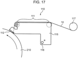
- the guide plate 112 may be configured to be movable between a position close to the anvil roll 210 (conveying roller) illustrated in FIG. 17 and a position away from the anvil roll 210 illustrated in FIG. 18 .
- the elastic member guide device 110 illustrated in FIG. 17 to 18 includes not only the multiple guide rolls 111 and the guide plate 112, but also a holding member 115 that holds both of the guide rolls 111 and the guide plate 112, a support shaft 116 that supports the holding member 115 to be swingable vertically, and a supply roll 117 disposed on upstream of the guide rolls 111 in the conveying direction of the elastic member 10.
- the support shaft 116 and a rotation shaft of the supply roll 117 are fixed at a predetermined position inside the manufacturing apparatus 100 to be prevented from being displaced.
- the multiple guide rolls 111 and the supply roll 117 are each provided in its outer peripheral surface with a groove for guiding the elastic member 10.
- the guide plate 112 can move between a position close to the anvil roll 210 (conveying roller) illustrated in FIG. 17 and a position away from the anvil roll 210 illustrated in FIG. 18 .
- the elastic member 10 is pressed by the guide plate 112 from above and moved from the supply roll 117 to the multiple guide rolls 111, and the guide plate 112 in this order to be fed onto the outer peripheral surface of the anvil roll 210.
- the manufacturing apparatus for manufacturing a composite stretchable member is a manufacturing apparatus for manufacturing a composite stretchable member including the two sheets and the multiple elastic members sandwiched between the two sheets by bonding the two sheets to each other and bonding the sheets to the multiple elastic members while conveying each of the sheets in a longitudinal direction thereof, the manufacturing apparatus comprising: a bonding device that welds and bonds the multiple elastic members to the two sheets, and the two sheets to each other, while the multiple elastic members are sandwiched between the two sheets being conveyed; and a guide device that guides the two sheets and the multiple elastic members to the bonding device in such a manner that each of the multiple elastic members extends in a longitudinal direction thereof and is sandwiched between the two sheets, wherein: the bonding device includes: a conveying roller that has an outer peripheral surface used for conveying the two sheets sandwiching the multiple elastic members in the longitudinal direction of each of the two sheets and that rotates about an axis predetermined; and a compressing device that faces the outer peripheral surface of the conveying roller to compress
- the present inventors have found that when a distance in which the elastic member moves in the air between the guide groove of the guide member and the groove of the conveying roller, i.e., a free distance of the elastic member, is reduced to a predetermined distance or less, the elastic member can be reliably guided to the groove of the conveying roller and can be prevented from being detached from the groove, and thus having fabricated the manufacturing apparatus.
- the manufacturing apparatus described above is configured such that disposing the guide member to allow the elastic member positioned between the guide groove and the groove of the conveying roller to have a length of 30 mm or less enables reducing the defect in which the elastic member is detached from the groove of the conveying roller when the elastic member is fed from the guide groove to the groove of the conveying roller. As a result, the function of preventing cutting of the elastic member 10 can be improved.
- the manufacturing apparatus for manufacturing a composite stretchable member described above is preferably configured such that the guide member is disposed to allow the elastic members positioned between the guide grooves and the corresponding grooves of the conveying roller to each have a length of 15 mm or less.
- the configuration described above enables reducing the defect in which the elastic member is detached from the groove of the conveying roller when the elastic member is fed from the guide groove to the groove of the conveying roller by disposing the guide member to allow the elastic member positioned between the guide groove and the groove of the conveying roller to have a length of 15 mm or less. As a result, the function of preventing cutting of the elastic member 10 can be further improved.
- the manufacturing apparatus for manufacturing a composite stretchable member described above is preferably configured such that the guide member is disposed to allow a shortest distance between a bottom of each of the guide grooves and an outer peripheral surface of the protruding section of the conveying roller to be 1 mm or less.
- the configuration described above enables the guide groove to approach the outer peripheral surface of the protruding section of the conveying roller, and thus enables shortening a distance in which the elastic member leaves the guide groove and is inserted into the groove of the conveying roller. This enables further reducing the defect in which the elastic member is detached from the groove of the conveying roller. As a result, the function of preventing cutting of the elastic member can be further improved.
- the manufacturing apparatus for manufacturing a composite stretchable member described above is preferably configured such that the guide member is formed in a plate-like shape, the leading end is an edge of the guide member in a plate-like shape, the edge being closest to the outer peripheral surface of the conveying roller and having a tapered shape, and the multiple guide grooves are formed at the leading end tapered.
- the configuration described above enables the guide member to be disposed close to the outer peripheral surface of the conveying roller without interfering with the conveying roller and the sheet wound around the outer peripheral surface of the conveying roller, by using the guide member in a plate-like shape with the leading end tapered. This enables further reducing the defect in which the elastic member is detached from the groove of the conveying roller, by shortening the distance between the guide groove and the groove of the anvil roll.
- the guide groove is formed at the leading end tapered, so that frictional resistance between the elastic member and the guide member when the elastic member passes through the guide groove can be reduced. As a result, the function of preventing cutting of the elastic member can be further improved.
- the manufacturing apparatus for manufacturing a composite stretchable member described above is preferably configured such that the leading end of the guide member is disposed upstream of a contact point at which the elastic members are in contact with the outer peripheral surface of the conveying roller in a rotation direction of the conveying roller, the leading end of the guide member facing upstream, and the guide plate is disposed to allow a surface of the guide plate facing the conveying roller to form an angle of 30 degrees or less with respect to a tangent line of the conveying roller at the contact point.
- the configuration described above enables the bottom of the guide groove to approach the outer peripheral surface of the conveying roller, and thus enables shortening a distance in which the elastic member leaves the guide groove and is inserted into the groove of the conveying roller. This enables further reducing the defect in which the elastic member is detached from the groove of the conveying roller. As a result, the function of preventing cutting of the elastic member can be further improved.
- the manufacturing apparatus for manufacturing a composite stretchable member described above preferably further includes a nip roll that is disposed upstream of the compressing device in the conveying direction of the sheet to sandwich the two sheets and the elastic members in cooperation with the conveying roller in a region where the elastic members are inserted into the corresponding grooves of the conveying roller.
- the configuration described above enables further reducing a defect in which the elastic member inserted into the groove of the conveying roller is detached from the groove of the conveying roller before reaching the compressing device. As a result, the function of preventing cutting of the elastic member can be further improved. Additionally, even when the elastic member contracts and tries to return when the elastic member is cut downstream of the nip roll, return of the elastic member is prevented because an end portion of the elastic member is sandwiched between the nip roll and the conveying roller. This facilitates restoration work of the manufacturing apparatus.
- the manufacturing apparatus for manufacturing a composite stretchable member described above preferably further includes a guide roll that is disposed upstream of the guide member in the conveying direction of the elastic members to guide the elastic members into the corresponding guide grooves.
- the configuration described above enables the elastic member to be reliably guided to the guide groove, so that the defect in which the elastic member is detached from the guide groove can be prevented.
- the manufacturing apparatus for manufacturing a composite stretchable member described above is preferably configured such that the guide roll is disposed to allow a distance in which the elastic members are separated from the guide roll and inserted into the corresponding guide grooves to be 50 mm or more.
- the configuration described above enables eliminating influence on the elastic member due to rotation unevenness and rattling of the guide roll, such as a slack of the elastic member.
- the manufacturing apparatus for manufacturing a composite stretchable member described above is preferably configured such that a conveying distance from a position where the guide member comes into contact with the corresponding grooves of the conveying roller to a position where the guide member is compressed by the compressing device is 150 mm or less.
- the configuration described above enables reducing a defect in which the elastic member is detached from the groove of the conveying roller while the elastic member is compressed by the compressing device after coming into contact with the groove of the conveying roller. As a result, the function of preventing cutting of the elastic member can be further improved.
- the manufacturing apparatus for manufacturing a composite stretchable member described above is preferably configured such that the guide member is movable between a position close to the conveying roller and a position away from the conveying roller.
- the configuration described above enables facilitating work of setting the elastic member in the guide device by moving the guide member to the position away from the conveying roller.
- the manufacturing apparatus for manufacturing a composite stretchable member of the present embodiment enables improving the function of preventing cutting by reducing the defect in which the elastic member is detached from the groove of the conveying roller.
Landscapes
- Health & Medical Sciences (AREA)
- Engineering & Computer Science (AREA)
- Vascular Medicine (AREA)
- Epidemiology (AREA)
- Biomedical Technology (AREA)
- Heart & Thoracic Surgery (AREA)
- Life Sciences & Earth Sciences (AREA)
- Animal Behavior & Ethology (AREA)
- General Health & Medical Sciences (AREA)
- Public Health (AREA)
- Veterinary Medicine (AREA)
- Manufacturing & Machinery (AREA)
- Absorbent Articles And Supports Therefor (AREA)
- Laminated Bodies (AREA)
Abstract
Description
- The present invention relates to a manufacturing apparatus for manufacturing a composite stretchable member.
- Wearing articles such as a disposable diaper having a waistline portion and a crotch portion have been known. In the wearing article such as the disposable diaper, the waistline portion of the wearing article may be formed of a composite stretchable member, which is stretchable, to improve wearing comfort.
- As an apparatus for manufacturing a composite stretchable member, for example, an apparatus described in
Patent Literature 1 is known. - The apparatus described in
Patent Literature 1 performs welding processing with an elastically stretchable member sandwiched between two sheets made of a nonwoven fabric or the like by feeding these two sheets and the elastically stretchable member to a nip between an ultrasonic welding horn and an anvil roll for conveying sheets. - The anvil roll is provided on its outer periphery with a seal pattern protruding section, and a welding portion is formed on each of the two sheets corresponding to the seal pattern protruding section. The seal pattern protruding section is provided with a groove formed corresponding to a portion where the elastically stretchable member is disposed. The groove has a depth that is set to cause a part of the elastically stretchable member to protrude from the groove when the elastically stretchable member is inserted into the groove.
- Inserting a part of the elastically stretchable member into the groove reduces pressure for sandwiching the elastically stretchable member when the two sheets and the elastically stretchable member are ultrasonically welded while being sandwiched between the ultrasonic welding horn and the seal pattern protruding section of the anvil roll. This enables the two sheets and the elastically stretchable member to be welded without cutting the elastically stretchable member.
- Thus, welding the elastically stretchable member to two sheets without cutting the elastically stretchable member requires the elastically stretchable member to be prevented from being detached from the groove of the seal pattern protruding section. For this reason, the apparatus described in
Patent Literature 1 is provided with a guide member upstream of the anvil roll in a direction of supplying the elastically stretchable member to the anvil roll. The guide member is disposed away from an outer peripheral surface of the anvil roll, and guides the elastically stretchable member into the groove of the seal pattern protruding section on the anvil roll. - The apparatus of
Patent Literature 1 is configured to guide the elastically stretchable member into the groove of the seal pattern protruding section on the anvil roll using the guide member, and the elastically stretchable member may be detached from the groove due to influence of vibration of the apparatus or the like. This requires to improve a function of preventing cutting by reducing a defect in which the elastically stretchable member is detached from the groove. - Patent Literature 1: International Publication
WO 2016/208502 A - It is an object of the present invention to provide a manufacturing apparatus for manufacturing a composite stretchable member capable of improving a function of preventing cutting by reducing a defect in which an elastic member is detached from a groove of a conveying roller.
- To solve the problem above, a manufacturing apparatus for manufacturing a composite stretchable member according to the present invention is configured to bond two sheets to each other and bond the sheets to multiple elastic members while conveying each of the sheets in a longitudinal direction to manufacture a composite stretchable member including the two sheets, and the multiple elastic members sandwiched between the two sheets, the manufacturing apparatus for manufacturing a composite stretchable member including: a bonding device that welds and bonds the multiple elastic members to the two sheets, and the two sheets to each other, while the multiple elastic members are sandwiched between the two sheets being conveyed; and a guide device that guides the two sheets and the multiple elastic members to the bonding device in such a manner that each of the multiple elastic members extends in a longitudinal direction thereof and is sandwiched between the two sheets, the bonding device having: a conveying roller that has an outer peripheral surface used for conveying the two sheets sandwiching the multiple elastic members in the longitudinal direction of each of the two sheets and that rotates about an axis predetermined; and a compressing device that faces the outer peripheral surface of the conveying roller to compress the two sheets sandwiching the multiple elastic members between the outer peripheral surface of the conveying roller and the compressing device, the bonding device is configured to apply heat to the two sheets between the conveying roller and the compressing device, the outer peripheral surface of the conveying roller is provided with at least one protruding section formed protruding radially outward from the outer peripheral surface, the at least one protruding section includes multiple grooves extending in a conveying direction of the conveying roller and is away from each other in a direction parallel to the axis, the guide device having a guide member provided with a leading end closest to the outer peripheral surface of the conveying roller, the leading end being provided with the multiple guide grooves that hold the corresponding multiple elastic members, while being away from each other in a direction parallel to the axis of the conveying roller, to guide the multiple elastic members into the corresponding multiple grooves of the conveying roller, and the guide member being disposed to allow each of the multiple elastic members positioned between the guide grooves and the corresponding grooves of the conveying roller to have a length of 30 mm or less.
-
-
FIG. 1 is a plan view of a composite stretchable member manufactured by a manufacturing apparatus according to an embodiment of the present invention. -
FIG. 2 is a part of a sectional view taken along line II-II inFIG. 1 . -
FIG. 3 is a schematic sectional view illustrating a section of an elastic member. -
FIG. 4 is a view corresponding toFIG. 1 and schematically illustrating a bonding section. -
FIG. 5 is an enlarged view of a part ofFIG. 1 . -
FIG. 6 is a schematic view illustrating a configuration of a manufacturing apparatus for manufacturing a composite stretchable member according to an embodiment of the present invention. -
FIG. 7 is a plan view of the guide plate ofFIG. 6 . -
FIG. 8 is a side view of the guide plate ofFIG. 7 . -
FIG. 9 is an enlarged view of a guide groove of the guide plate ofFIG. 7 . -
FIG. 10A is an enlarged view of the guide plate and a peripheral portion thereof of the manufacturing apparatus ofFIG. 6 , andFIG. 10B is an enlarged view of a portion where an elastic member is fed from a guide groove of the guide plate ofFIG. 10A to an anvil roll. -
FIG. 11 is a view illustrating an outer peripheral surface of the anvil roll ofFIG. 6 . -
FIG. 12 is an enlarged view illustrating protruding sections and grooves on the outer peripheral surface of the anvil roll inFIG. 11 . -
FIG. 13 is a sectional view taken along line XIII-XIII inFIG. 12 . -
FIG. 14 is a sectional view taken along line XIV-XIV inFIG. 12 . -
FIG. 15 is a developed view of a disposable diaper using a composite stretchable member. -
FIG. 16 is a view schematically illustratingstages 1 to 3 for illustrating a method for manufacturing the disposable diaper illustrated inFIG. 15 . -
FIG. 17 is a view illustrating a manufacturing apparatus according to a modification of the present invention, being configured such that a guide plate is movable between a position close to an anvil roll and a position away from the anvil roll, and is a view illustrating a state in which the guide plate is at the position close to the anvil roll (position during operation of the manufacturing apparatus). -
FIG. 18 is a view illustrating a state in which the guide plate ofFIG. 17 is at the position away from the anvil roll (a position when an elastic member such as a rubber thread is allowed to pass). - Hereinafter, embodiments of the present invention will be described with reference to the accompanying drawings. The following embodiments are merely examples embodying the present invention, and do not limit the technical scope of the present invention.
-
FIG. 1 is a plan view of a composite stretchable member manufactured by a manufacturing apparatus according to an embodiment of the present invention.FIG. 2 is a part of a sectional view taken along line II-II inFIG. 1 . - A composite
stretchable member 1 includes twoelongated sheets elastic members 10 stretchable in a longitudinal direction A. Each of theelastic members 10 is disposed between thesheets FIG. 1 ) of each of thesheets sheets elastic members 10 are disposed at equal intervals in a width direction B (a direction orthogonal to the longitudinal direction A of thesheets sheets sheets - In the present embodiment, a sheet-like material such as a nonwoven fabric is used as the
sheets - An
elastic member 10 is made of a material that is more elastic than the material (nonwoven fabric or the like) of thesheets elastic member 10 is not particularly limited in the present invention. As an example of the present embodiment is illustrated inFIG. 3 , theelastic member 10 is a multi-strand provided with multiple rubber threads (fibrous elastic bodies) 10a collected in a bundle, and includes at least some of therubber threads 10a each having the periphery covered with a coveringlayer 10b, for example. Specifically, therubber threads 10a disposed particularly in an outer peripheral portion among themultiple rubber threads 10a are each covered with the coveringlayer 10b. Everyrubber thread 10a may be covered with the coveringlayer 10b. - Examples of the material of the
rubber thread 10a include polyurethane. Examples of the material of the coveringlayer 10b include a lubricant such as silicon oil or magnesium stearate. -
FIG. 1 illustrates abonding section 4 in a lattice shape on which thesheets sheets elastic members 10. -
FIG. 4 schematically illustrates the bonding section ofFIG. 1 . As illustrated inFIGS. 1 and4 , thebonding section 4 includes multiplefirst bonding portions 4a and multiplesecond bonding portions 4b. - The
first bonding portions 4a are disposed at equal intervals in the longitudinal direction A of thesheets sheets - The
second bonding portions 4b are also disposed at equal intervals in the longitudinal direction A of thesheets sheets second bonding portions 4b extend intersecting the correspondingfirst bonding portions 4a, thereby forming thebonding section 4 in a lattice shape. - In the present embodiment, both a
first bonding portion 4a and asecond bonding portion 4b are inclined with respect to the width direction B of thesheets - The
first bonding portion 4a and thesecond bonding portion 4b each have a symmetrical shape with respect to both straight lines extending in the longitudinal direction A and the width direction B of thesheets first bonding portions 4a and thesecond bonding portions 4b are disposed such that a clearance between two adjacentfirst bonding portions 4a is equal to a clearance between two adjacentsecond bonding portions 4b. This causes thebonding section 4 to have multiple defined rhombuses each having diagonals extend along the longitudinal direction A and the width direction B of thesheets first bonding portion 4a and thesecond bonding portion 4b are each inclined with respect to the width direction B of thesheets first bonding portion 4a and thesecond bonding portion 4b form a rhombus extending in the widthdirection B. Intersections 4c between thefirst bonding portions 4a and the correspondingsecond bonding portions 4b, which may be referred to below as bonding-portion side intersections, are arranged at equal intervals on a straight line extending in the longitudinal direction A of thesheets sheets - Each
bonding section 4 intersects all theelastic members 10 and extends along a line intersecting an extending direction (i.e., the longitudinal direction A) of theelastic members 10. Specifically, eachbonding section 4 extends between opposite outer portions of thesheets elastic members 10 are disposed. - Each of the
elastic members 10 and thebonding section 4 intersect at a portion excluding the bonding-portion side intersection 4c, i.e., at a position away from the bonding-portion side intersection 4c, and each of theelastic members 10 is bonded to thesheets - With reference to
FIG. 5 that is an enlarged view of a part ofFIG. 1 , the configuration will be specifically described. - Each
elastic member 10 is disposed passing through between two adjacent bonding-portion side intersections 4c on eachfirst bonding portion 4a (e.g., between a bonding-portion side intersection 4c_1 and a bonding-portion side intersection 4c_2, and between a bonding-portion side intersection 4c_2 and a bonding-portion side intersection 4c_3 illustrated inFIG. 5 ). That is, a first elastic-member side intersection 4d, which is an intersection between eachelastic member 10 and the corresponding one of thefirst bonding portions 4a, is positioned between two adjacent bonding-portion side intersections 4c on thefirst bonding portion 4a, and theelastic member 10 is bonded to thesheets position 4d. - Similarly, each
elastic member 10 is disposed passing through between adjacent bonding-portion side intersections 4c on eachsecond bonding portion 4b (e.g., between a bonding-portion side intersection 4c_4 and a bonding-portion side intersection 4c_2, and between a bonding-portion side intersection 4c_2 and a bonding-portion side intersection 4c_5 illustrated inFIG. 5 ). That is, a second elastic-member side intersection 4e, which is an intersection between eachelastic member 10 and the corresponding one of thesecond bonding portions 4b, is positioned between two adjacent bonding-portion side intersections 4c on thesecond bonding portion 4b, and theelastic member 10 is bonded to thesheets position 4e. - In the present embodiment, each
elastic member 10 passes through the center of the adjacent bonding-portion side intersections first bonding portion 4a, and the center of the adjacent bonding-portion side intersections second bonding portion 4b, and intersects thefirst bonding portion 4a and thesecond bonding portion 4b at the center position to be bonded to thesheets - This causes the first elastic-
member side intersection 4d and the second elastic-member side intersection 4e to be alternately arranged on a straight line extending in the width direction B of both thesheets elastic members 10 and thebonding section 4, i.e.,bonding points elastic members 10 and thesheets sheets - In the
bonding section 4, thesheets sheets elastic member 10 are bonded to each other by welding. In the present embodiment, these are ultrasonically welded. - The
sheets elastic member 10 and thesheets sheets covering layer 10b of theelastic member 10 is melted. - Specifically, in the present embodiment, a rubber thread having a melting point of about 200°C is used as the
rubber thread 10a, and thecovering layer 10b is made of magnesium stearate (melting point: about 120°C) having a lower melting point than the rubber thread. When theelastic member 10 and thesheets covering layer 10b is melted to weld thecovering layer 10b to thesheets rubber thread 10a. - Next, a manufacturing apparatus for manufacturing the composite
stretchable member 1 will be described. -
FIG. 6 is a schematic view of amanufacturing apparatus 100 according to an embodiment of the present invention. - The
manufacturing apparatus 100 includes: abonding device 200 that ultrasonically welds and bonds theelastic member 10 to thesheets sheets elastic member 10 is sandwiched between thesheets first guide roller 102 that guides thesheet 2a to the bonding device 200 (specifically, ananvil roll 210 described later); an elastic member guide device (guide device) 110 that supplies theelastic member 10 to thebonding device 200; a nip roll (second guide roller) 104 that guides thesheet 2b to thebonding device 200 and presses the twosheets elastic member 10; and athird guide roller 106 that guides a bonded sheet or the like, i.e., the compositestretchable member 1. - The
bonding device 200 includes the anvil roll (conveying roller) 210 and a horn (compressing device) 220. - The
anvil roll 210 is a rotating member that rotates about an axis extending in a direction orthogonal to the paper surface ofFIG. 6 . Hereinafter, the direction orthogonal to the paper surface ofFIG. 6 is referred to as a "front-back direction". Theanvil roll 210 is rotatably attached to a rotation shaft, as a rotation center, extending horizontally with respect to a vertical wall portion of an apparatus, such as a panel (not illustrated). Theanvil roll 210 rotates to convey theelastic member 10 guided by the elasticmember guide device 110 while theelastic member 10 is sandwiched between thesheets rollers anvil roll 210. In the example illustrated inFIG. 6 , theanvil roll 210 rotates counterclockwise inFIG. 6 . Hereinafter, thesheets elastic member 10 may be referred to as pre-bonding sheets. - As illustrated in
FIG. 11 , the outer peripheral surface of theanvil roll 210 is provided with a protrudingsection 212 protruding radially outward. The protrudingsection 212 is provided on the outer peripheral surface of theanvil roll 210 throughout the outer peripheral surface in its circumferential direction. The protrudingsection 212 has a shape corresponding to that of thebonding section 4. In the present embodiment, thebonding section 4 has a rhombic lattice shape as described above, and the protrudingsection 212 has a rhombic lattice shape correspondingly. - Specifically, the protruding
section 212 includes first protrudingportions 212a for forming thefirst bonding portions 4a and second protrudingportions 212b for forming thesecond bonding portions 4b. - The first protruding
portions 212a extend along a direction (first direction C1) intersecting the circumferential direction of the anvil roll 210 (conveying direction of the anvil roll 210), i.e., along a line intersecting the circumferential direction, and are disposed parallel to each other at equal intervals in the circumferential direction. The second protrudingportions 212b extend along a direction (second direction C2) intersecting the circumferential direction of theanvil roll 210 and the first direction C1, i.e., along a line intersecting the circumferential direction, and are disposed parallel to each other at equal intervals in the circumferential direction of theanvil roll 210. - The first protruding
portions 212a and the second protrudingportions 212b are each symmetrically inclined at an angle smaller than 45 degrees with respect to the front-back direction, and are provided such that a clearance between two adjacent first protrudingportions 212a is equal to a clearance between two adjacent second protrudingportions 212b, andintersections 212c of the first protrudingportions 212a and the corresponding second protrudingportions 212b are arranged at equal intervals on a line extending in the front-back direction and the circumferential direction of theanvil roll 210. - As illustrated in
FIG. 12 that is an enlarged view of a part ofFIG. 11 ,FIG. 13 that is a sectional view taken along line XIII-XIII ofFIG. 12 , andFIG. 14 that is a sectional view taken along line XIV-XIV ofFIG. 12 , the first protrudingportion 212a and the second protrudingportion 212b are each provided with a groove 214 (214a or 214b) recessed inward in a radial direction of theanvil roll 210. As illustrated inFIG. 13 and the like, the first protrudingportions 212a and the second protrudingportions 212b are each provided withmultiple grooves 214 at respective positions away from each other in the longitudinal directions C1 and C2 thereof. - Into these
grooves 214, a portion of thesheet 2a (sheet disposed on the anvil roll 210) with theelastic member 10 disposed is inserted. Thus, placement of theelastic members 10 for thebonding section 4 coincides with placement of the grooves for the protrudingsection 212. - Specifically, in the present embodiment, as illustrated in
FIG. 12 , the first protrudingportions 212a are each provided with the grooves (first grooves) 214a extending in the circumferential direction of theanvil roll 210, being each formed in a portion betweenintersections 212c with the corresponding second protrudingportions 212b, more specifically, in a central portion ofadjacent intersections 212c. The second protrudingportions 212b are each provided with the grooves (second grooves) 214b that are each formed in a portion betweenintersections 212c with the corresponding first protrudingportions 212a, more specifically, in a central portion ofadjacent intersections 212c. Thesegrooves 214 are provided at equal intervals on a line extending along the circumferential direction of theanvil roll 210, and are provided at equal intervals on a straight line extending along the front-back direction (i.e., a direction parallel to the rotation shaft of theanvil roll 210, in other words, the same direction as the extending direction of the rotation shaft). - The
sheet 2a is conveyed by theanvil roll 210 while having a portion where theelastic member 10 is disposed, the portion being inserted into thecorresponding grooves 214. As described above, in the present embodiment, theelastic members 10 are guided into thecorresponding grooves 214 by aguide plate 112 provided withguide grooves 114b at positions corresponding to therespective grooves 214, so that theelastic members 10 are each stably disposed at an appropriate position on thesheet 2a. - In the present embodiment, the
sheet 2a together with theelastic members 10 that are partially inserted into thecorresponding grooves 214 are conveyed by theanvil roll 210. Only thesheet 2a with portions inserted into the grooves may be conveyed. - The
grooves 214 are formed in the protrudingsection 212 at portions where the respectiveelastic members 10 are disposed as described above, so that at least a part of each of theelastic members 10 disposed on a pre-bonding sheet is retracted in the corresponding grooves when the pre-bonding sheet is compressed during bonding. Thus, anelastic member 10 is prevented from being cut when being compressed. - However, when the
groove 214 has an excessive sectional area, theelastic member 10 may be less likely to be appropriately bonded to thesheets FIG. 14 , when theelastic member 10 with a natural length is disposed in thegroove 214, a part of theelastic member 10 protrudes outward from thegroove 214, and the rest of theelastic member 10 is accommodated in thegroove 214. Specifically, thegroove 214 is configured to have a section taken along a plane orthogonal to the circumferential direction (conveying direction) of theanvil roll 210, the section having a shape in which when theelastic member 10 is disposed in thegroove 214 with the natural length, a part of theelastic member 10 protrudes outward in the radial direction of theanvil roll 210 from a linear imaginary line L10 connecting open ends (Q1, Q2) of thegroove 214. Thegroove 214 is also configured to have the sectional shape in which when theelastic member 10 is extended from a natural state (e.g., when being elongated 300%) is disposed in thegroove 214, a part of theelastic member 10 protrudes outward in the radial direction of theanvil roll 210 from the linear imaginary line L10 connecting the open ends (Q1, Q2) of thegroove 214. Thegroove 214 described above preferably has a sectional shape of a substantially V-shape as illustrated inFIG. 14 . Thegroove 214 described above preferably has a sectional area S1 smaller than a sectional area of theelastic member 10 to be disposed. The sectional shape of thegroove 214 is not limited to a V-shape, and may be another shape such as a U-shape. - As described above, when the
groove 214 is formed with a sectional shape allowing theelastic member 10 to partially protrude, theelastic member 10 disposed in the groove and thesheets elastic member 10 is retracted into thegroove 214. Thus, thesheets elastic members 10 can be more reliably bonded to each other while theelastic members 10 is prevented from being damaged. Specifically, a portion of theelastic member 10 inside the imaginary line L10, i.e., the portion accommodated in thegroove 214, can be retracted inside the groove 214 (a side away from the horn 220) while pressure is appropriately applied to a portion of theelastic member 10, protruding outside the imaginary line L10 connecting the open ends Q1 and Q2 of thegroove 214, and thesheets elastic member 10 from being damaged while securing bonding force between theelastic member 10 and thesheets - In particular, when the sectional shape of the
groove 214 is set such that theelastic member 10 partially protrudes outward in the radial direction of theanvil roll 210 from the linear imaginary line L10 connecting the open ends (Q1, Q2) of thegroove 214 when theelastic member 10 elongated 300% is disposed in thegroove 214, thesheets elastic member 10 can be more reliably bonded to each other by being appropriately subjected to pressure while theelastic member 10 is prevented from being damaged. - The
horn 220 illustrated inFIGS. 6 and10A is a device that applies ultrasonic vibration to a pre-bonding sheet conveyed by theanvil roll 210 while compressing (pressurizing while sandwiching) the pre-bonding sheet with the outer peripheral surface of theanvil roll 210. Thehorn 220 is disposed to face the outer peripheral surface of theanvil roll 210. In the example ofFIG. 6 , thehorn 220 is disposed to face an upper portion of the outer peripheral surface of theanvil roll 210. Thehorn 220 is provided at its leading end with anoutput unit 221 that applies ultrasonic vibration toward the outer peripheral surface of theanvil roll 210. - The
horn 220 applies ultrasonic vibration to a pre-bonding sheet with theoutput unit 221 pressing against the pre-bonding sheet and compressing the pre-bonding sheet together with theanvil roll 210. This causes thesheets elastic member 10 is also melted, so that theelastic member 10 and thesheets output unit 221 compresses the pre-bonding sheet together with the protrudingsection 212, and bonds thesheets elastic member 10 to thesheets section 212. The leading end of theoutput unit 221 has a planar shape (SeeFIGS. 13 and14 ). - As described above, in the present embodiment, the
covering layer 10b is made of magnesium stearate having a lower melting point than therubber thread 10a. Thus, during welding between theelastic member 10 and thesheets covering layer 10b is melted to weld thecovering layer 10b to thesheets rubber thread 10a. - The
output unit 221 at the leading end of thehorn 220 extends in the front-back direction, and thehorn 220 applies ultrasonic vibration to the outer peripheral surface of theanvil roll 210 throughout in a rotation axis direction of theanvil roll 210. While a pre-bonding sheet is conveyed by theanvil roll 210, thehorn 220 always applies ultrasonic vibration. Thus, as the pre-bonding sheet is conveyed by theanvil roll 210, the pre-bonding sheet is continuously bonded. - As illustrated in
FIG. 6 , in the present embodiment, thesheet 2a is guided by thefirst guide roller 102 to a position separated upstream from thehorn 220 on the outer peripheral surface of theanvil roll 210. Thesheet 2a is conveyed toward thehorn 220 along the outer peripheral surface of theanvil roll 210 along with rotation of theanvil roll 210. - The
sheet 2b is introduced into a portion of the outer peripheral surface of theanvil roll 210, being near thehorn 220 and upstream of thehorn 220 in the conveying direction, by thenip roll 104. - The
elastic member 10 is introduced onto the outer peripheral surface of theanvil roll 210 at a position between a position where thesheet 2a is introduced onto theanvil roll 210 and a position where thesheet 2b is introduced onto theanvil roll 210 by the elasticmember guide device 110. As a result, theelastic member 10 is conveyed to a position facing thehorn 220 while being sandwiched between thesheets - Although the
sheet 2b may be introduced onto theanvil roll 210 from thenip roll 104 at any position between a position where theelastic member 10 is introduced and a position facing thehorn 220, the position is preferably on a side close to the position facing thehorn 220, and more preferably near the position facing thehorn 220. In the present embodiment, as illustrated inFIGS. 6 and10A , thenip roll 104 is disposed at a position closest upstream of thehorn 220 in the conveying direction of thesheets FIG. 10A ). This configuration enables preventing theelastic member 10 introduced onto the outer peripheral surface of theanvil roll 210 from being covered with thesheet 2b at an early stage and from causing positional deviation. - The
elastic members 10 are introduced onto the outer peripheral surface of theanvil roll 210 while being arranged parallel to each other in the front-back direction, and are placed on thesheet 2a, which is previously introduced onto the outer peripheral surface of theanvil roll 210, parallel to each other in the width direction B, on the outer peripheral surface of theanvil roll 210. Theelastic members 10 are each introduced onto theanvil roll 210 while being elongated in the circumferential direction of theanvil roll 210. In the present embodiment, theelastic members 10 are each introduced onto theanvil roll 210 while being elongated 300% of the natural state when the natural state is set to 100%. - Next, the elastic member guide device 110 (in particular, the guide plate 112) of the present embodiment will be described in detail.
- As illustrated in
FIGS. 6 and10 , the elasticmember guide device 110 includes multiple guide rolls 111 and aguide plate 112 in a plate-like shape as a guide member. - Each of the guide rolls 111 is a rotary member rotatable about its axis extending in the front-back direction, and guides the
elastic member 10 toward theanvil roll 210 while theelastic member 10 is elongated (e.g., elongated 300%). - As illustrated in
FIG. 6 to 10 , theguide plate 112 is a tabular member that guides theelastic members 10 to the corresponding grooves 214 (seeFIG. 11 to 14 ) formed on the outer peripheral surface of theanvil roll 210 while theelastic members 10 are separated from each other in the front-back direction, i.e., in a direction parallel to the axis of theanvil roll 210. - The
guide plate 112 has aleading end 114a, which is an edge closest to the outer peripheral surface of theanvil roll 210, and a proximal end disposed farther away from theanvil roll 210 than theleading end 114a. Theguide plate 112 is disposed to extend not only in a direction of coming into contact with and separating from theanvil roll 210 but also in the front-back direction. In the present embodiment, to prevent theguide plate 112 from interfering with thesheets guide plate 112 has a thickness t (dimension in a vertical direction illustrated inFIG. 8 ) that is set to be small, and has a thin plate shape. - The
leading end 114a of theguide plate 112 has a tapered shape. Specifically, as illustrated inFIG. 8 , theguide plate 112 is provided in its leading end portion (portion close to the anvil roll 210) with aninclined surface 114c that is inclined toward theleading end 114a to approach abottom surface 114d of theguide plate 112. Theinclined surface 114c and thebottom surface 114d form theleading end 114a tapered. In the present embodiment, theinclined surface 114c and thebottom surface 114d form an angle θ2 that is set to about 10 degrees. - As illustrated in
FIGS. 10A and 10B , theleading end 114a of theguide plate 112 is disposed upstream (right side inFIG. 10 ) of a contact point P2 at which theguide plate 112 is in contact with theelastic member 10 on the outer peripheral surface of theanvil roll 210 in the rotation direction (counterclockwise direction inFIG. 10 ) of theanvil roll 210 while facing upstream. Theguide plate 112 is fixed in a stationary manner at a predetermined position facing the outer peripheral surface of theanvil roll 210. InFIGS. 10A and 10B , theguide plate 112 is fixed to a fixingmember 113, which is fixed to a panel or the like inside the apparatus, by screwing or the like to be prevented from being displaced. - The
leading end 114a tapered of theguide plate 112 is provided withmultiple guide grooves 114b. Specifically, theguide grooves 114b are formed at respective positions away from each other at equal intervals in the front-back direction (direction parallel to the axis of the anvil roll 210) at theleading end 114a of theguide plate 112, and individually hold the respectiveelastic members 10 to guide theelastic members 10 into therespective grooves 214 of theanvil roll 210. As illustrated inFIG. 9 that illustrates a part of theguide grooves 114b inFIG. 7 in an enlarged manner, each of theguide grooves 114b is recessed from theleading end 114a of theinclined surface 114c toward the proximal end, and has a V-shape having an opening angle of 90 degrees. Theguide grooves 114b each have a sectional shape that is not limited to the V-shape, and that may be another shape such as a U-shape. These guidegrooves 114b reliably position and hold the respectiveelastic members 10 to guide theelastic members 10 onto the outer peripheral surface of theanvil roll 210 while separating theelastic members 10 from each other in the front-back direction. Theguide grooves 114b face therespective grooves 214 formed in theanvil roll 210 and are provided at the same intervals as thegrooves 214 to guide theelastic members 10 into therespective grooves 214. - The
leading end 114a of theguide plate 112 and theguide grooves 114b formed at theleading end 114a face in an opposite direction (i.e., a clockwise direction) to the rotation direction of the anvil roll 210 (the counterclockwise direction inFIGS. 6 and10A ). Thus, theelastic members 10 engaged into therespective guide grooves 114b are pulled by theanvil roll 210 rotating in the counterclockwise direction, and are bent at bottoms PI of therespective guide groove 114b. Each of theelastic members 10 then extends in a tangential direction of the contact P2 on the outer peripheral surface of theanvil roll 210, and is inserted into the corresponding one of the grooves 214 (seeFIG. 11 to 14 ) at the contact P2 on the outer peripheral surface of theanvil roll 210. - As illustrated in
FIGS. 10A and 10B , it is conceivable that as a length L1 (specifically, a distance L1 from the bottom PI of aguide groove 114b to the contact point P2 at which anelastic member 10 is in contact with the anvil roll 210) of theelastic member 10 positioned between theguide groove 114b and agroove 214 of theanvil roll 210 decreases in theguide plate 112, theelastic member 10 tends to be less likely to be detached from thegroove 214 of theanvil roll 210. - As a result of experimentally examining a correlation between the length L1 (i.e., a free distance L1 with which the
elastic member 10 moves in the air without being restrained) of theelastic member 10 positioned between theguide groove 114b and thegroove 214 of theanvil roll 210 and probability of vibration of theelastic member 10, the present inventors have found that there is a correlation as shown in Table 1 below. In the experiment, a linear rubber thread having a diameter of 0.1 mm or more was used as theelastic member 10, and a frequency of touches of the rubber thread and the amount of vibration of the rubber thread were observed for a certain period of time by continuously inserting the rubber thread from theguide groove 114b of theguide plate 112 into thegroove 214 of theanvil roll 210 in themanufacturing apparatus 100. Results of the experiment are shown in Table 1 below.[Table 1] FREE DISTANCE L1 15 mm OR LESS 15~30 mm OR LESS 30∼50 mm OR LESS VIBRATION SUPPRESSION EFFECT OF ELASTIC MEMBER (RUBBER THREAD) ⊚ △ × PROBABILITY OF VIBRATION OF RUBBER THREAD WITH DIAMETER OF 0.1 mm OR MORE 0.08% 4.66% 10% OR MORE - The experimental results in Table 1 show that when the free distance L1 of the rubber thread is 15 mm or less, the rubber thread having a diameter of 0.1 mm or more has a probability of vibration of 0.08%, resulting in good (double circle) in vibration suppression effect of the rubber thread.
- Even when having a free distance L1 of 15 mm to 30 mm or less in the range larger than 15 mm, the rubber thread has a probability of vibration of 4.66% that falls within the allowable probability (5%), and thus it can be seen that the vibration suppression effect of the rubber thread is a pass or a pass mark (triangle).
- When having a free distance L1 within a range of more than 30 mm, e.g., 30 mm to 50 mm or less, the rubber thread has a probability of vibration of 10% or more that greatly exceeds the allowable probability (5%), and thus it can be seen that the vibration suppression effect of the rubber thread is unacceptable (cross).
- To reduce a defect in which the
elastic member 10 such as a rubber thread is detached from thegroove 214 of theanvil roll 210 based on the above experimental results, theguide plate 112 of the present embodiment is preferably disposed such that theelastic member 10 positioned between theguide groove 114b and thegroove 214 of theanvil roll 210 has a length L1 of 30 mm or less, preferably of 15 mm or less, and practically within a range of 1 mm to 30 mm, preferably within a range of 1 mm to 15 mm. The distance L1 is set to be larger than zero to prevent theguide plate 112 from coming into contact with the anvil roll 210 (specifically, thesheet 2a wound around the outer peripheral surface of the anvil roll 210), i.e., to allow theguide plate 112 to be separated by a thickness of thesheet 2a or more. - As illustrated in
FIG. 10B , theguide plate 112 is disposed such that a gap δ1 between the bottom PI of theguide groove 114b and the outer peripheral surface of the protrudingsection 212 of theanvil roll 210 is 1 mm or less, preferably is 0.3 mm or less, and practically within a range of 0.1 mm to 1 mm, preferably within a range of 0.1 mm to 0.3 mm. - As illustrated in
FIG. 10B , theguide plate 112 is disposed such that thebottom surface 114d facing theanvil roll 210 forms an angle θ1 of 30 degrees or less (practically, an angle within a range of 1 to 30 degrees) with respect to a tangent line of theanvil roll 210 at the contact point P2 where theanvil roll 210 and theelastic member 10 are in contact with each other. - As illustrated in
FIGS. 6 and10A , the multiple guide rolls 111 is disposed upstream of theguide plate 112 in the conveying direction of theelastic member 10, and guides theelastic member 10 into theguide groove 114b. Each of the guide rolls 111 is provided in its outer peripheral surface with grooves (not illustrated) away from each other in an extending direction of a rotation shaft of theguide roll 111 to guide theelastic members 10 into therespective guide grooves 114b. - As illustrated in
FIG. 10A , aguide roll 111A positioned most downstream of the multiple guide rolls 111 is disposed to have a distance L2 of 50 mm or more in which theelastic member 10 is separated from the guide roll from theguide roll 111 and inserted into theguide groove 114b to prevent influence due to rotation unevenness and rattling of theguide roll 111A (e.g., a slack of theelastic member 10 and the like). - As illustrated in
FIGS. 6 and10A , thenip roll 104 is disposed upstream of thehorn 220. The niproll 104 can sandwich two sheets and theelastic member 10 in cooperation with theanvil roll 210 in a region where theelastic member 10 is inserted into thegroove 214 of theanvil roll 210, i.e., a section from a first position (i.e., a contact point between theanvil roll 210 and the elastic member 10) P2 (seeFIG. 10B ) where theelastic member 10 is inserted into thegroove 214 in the outer peripheral surface of theanvil roll 210 to the output unit 221 (seeFIG. 10A ) of thehorn 220. - As illustrated in
FIG. 10A , in the present embodiment, a conveying distance L3, in which the elastic member is compressed by thehorn 220 after coming into contact with thegroove 214 of theanvil roll 210, is set to 150 mm or less (practically, a range of 1 mm to 150 mm) to reduce a defect in which theelastic member 10 is detached from thegroove 214 of theanvil roll 210 while theelastic member 10 is compressed by thehorn 220 after coming into contact with thegroove 214 of theanvil roll 210. - The conveying distance L3 described above has an optimum numerical value derived from experiments performed by the present inventors. Specifically, as shown in Table 2 below, when a linear rubber thread having a diameter of 0.1 mm or more was used as the
elastic member 10, a relationship between the conveying distance L3, in which the rubber thread is compressed by thehorn 220 after coming into contact with thegroove 214 of theanvil roll 210, and the probability of vibration of the rubber thread, was examined through experiments.[Table 2] CONVEYING DISTANCE L3 FREE DISTANCE L1 = 11 mm FREE DISTANCE L1 = 19 mm 20 mm 0.08% 1.12% 150 mm 0.16% 3.66% 300 mm 5.73% 9.62% - The experimental results in Table 2 show that when the conveying distance L3 of the rubber thread is 150 mm, the probability of vibration of the rubber thread under conditions where the free distance L1 is 11 mm is 0.16%, and the probability of vibration of the rubber thread under conditions where the free distance L1 is 19 mm is 3.66%, which fall within an allowable probability (5%), and thus the vibration suppression effect of the rubber thread is sufficiently exhibited (passed). Table 2 also shows that when the conveying distance L3 is 20 mm, the probability of vibration of the rubber thread under the conditions where the free distance L1 is 11 mm decreases to 0.08%, and the probability of vibration of the rubber thread under the conditions where the free distance L1 is 19 mm decreases to 1.12%.
- In contrast, when the conveying distance L3 of the rubber thread is 300 mm, the probability of vibration of the rubber thread under the conditions where the free distance L1 is 11 mm is 5.73%, and the probability of vibration of the rubber thread under the conditions where the free distance L1 is 19 mm is 9.62%, which greatly exceeds the allowable probability (5%), and thus the vibration suppression effect of the rubber thread is insufficient (failed).
- The experimental results in Table 2 above show that the conveying distance L3 is preferably set to 150 mm or less to reduce a defect in which the
elastic member 10 is detached from thegroove 214 of theanvil roll 210 while theelastic member 10 is compressed by thehorn 220 after coming into contact with thegroove 214 of theanvil roll 210. -
FIG. 15 is a schematic view illustrating a disposable diaper (wearing article) 20 using the compositestretchable member 1 as a usage example of the compositestretchable member 1 configured as described above. - The
disposable diaper 20 includes awaistline portion 21 having a frontabdomen portion 21a disposed on the front of the abdomen of a wearer and arear back portion 21b disposed on the buttocks of the wearer, and acrotch portion 22 disposed at the crotch of the wearer. The compositestretchable member 1 of the present embodiment is used for the frontabdomen portion 21a and therear back portion 21b. For example, the compositestretchable member 1 is applied to the frontabdomen portion 21a and therear back portion 21b such that the extending direction of the compositestretchable member 1 aligns with a waistline direction (left-right direction inFIG. 15 ) at the time of wearing. -
FIG. 16 is a view illustrating an example of a method for manufacturing thedisposable diaper 20, and the present invention is not limited thereto. The manufacturing method illustrated inFIG. 16 includesstages 1 to 3. First, in thestage 1, a pair ofcontinuous bodies 101 in which compositestretchable members 1 are connected in the conveying direction is prepared. That is, acontinuous body 101 for forming the frontabdomen portion 21a and acontinuous body 101 for forming therear back portion 21b are prepared. Then, both thecontinuous bodies 101 are conveyed in the longitudinal direction of thecontinuous bodies 101 while being disposed parallel to each other, and thecrotch portion 22 is placed on thecontinuous bodies 101 such that the longitudinal direction of the crotch portion is orthogonal to the longitudinal direction of thecontinuous bodies 101. For example,crotch portions 22 are placed away from each other in the conveying direction. Then, thecrotch portions 22 are bonded thecontinuous bodies 101 to form a bonded body 102 (step of forming a bonded body). - Next, in the
stage 2, a hole serving as a leg opening is formed between thecrotch portions 22 adjacent to each other. After that, the bondedbody 102 is folded in two along a center line CL1 in the width direction (direction orthogonal to the longitudinal direction of the continuous bodies 101) as a fold such that thecrotch portion 22 is positioned inside (step of folding in two). - Next, in the
stage 3, portions of the respectivecontinuous bodies 101 positioned in the middle of theadjacent crotch portions 22, which overlap each other, are bonded to each other along a direction orthogonal to the longitudinal direction of thecontinuous bodies 101 to form a side seal SS (step of sealing a side), and thecontinuous bodies 101 are cut along a cutting line K in the side seal portion (step of cutting). - In this manner, the
disposable diaper 20 including the waistline portion 21 (the frontabdomen portion 21a and therear back portion 21b) that is formed of the compositestretchable member 1 to stretch and contract in the waistline direction is manufactured. - In the present embodiment, the step of opening the hole serving as the leg opening may or may not be performed before the
crotch portions 22 are bonded to thecontinuous bodies 101. Additionally, eachelastic member 10 of the compositestretchable member 1 may be bonded to twosheets elastic member 10 due to cutting along the cutting line K can be prevented. - The
manufacturing apparatus 100 for manufacturing a composite stretchable member of the present embodiment is configured such that as illustrated inFIG. 6 to 10 , the elasticmember guide device 110 includes theguide plate 112 in a plate-like shape as a guide member that guideselastic members 10 to therespective grooves 214 in the outer peripheral surface of theanvil roll 210. Theguide plate 112 includes theleading end 114a closest to the outer peripheral surface of theanvil roll 210, and theguide grooves 114b provided at theleading end 114a and holding the respectiveelastic members 10 in a state away from each other in a direction parallel to the axis of theanvil roll 210 to guide theelastic members 10 to therespective grooves 214 in the outer peripheral surface of theanvil roll 210 in the state away from each other in the direction parallel to the axis of theanvil roll 210. Theguide plate 112 is disposed to allow theelastic member 10 positioned between theguide groove 114b and thegroove 214 of theanvil roll 210 to have a length L1 (free distance L1) of 30 mm or less. - As described above, disposing the
guide plate 112 to allow theelastic member 10 positioned between theguide groove 114b and thegroove 214 of theanvil roll 210 to have the length L1 of 30 mm or less enables reducing a defect in which theelastic member 10 is detached from thegroove 214 of theanvil roll 210 when theelastic member 10 is fed from theguide groove 114b to thegroove 214 of theanvil roll 210. As a result, a function of preventing cutting of theelastic member 10 can be improved. - The
guide plate 112 is preferably disposed to allow theelastic member 10 positioned between theguide groove 114b and thegroove 214 of theanvil roll 210 to have a length L1 of 15 mm or less. This case enables further reducing the defect in which theelastic member 10 is detached from thegroove 214 of theanvil roll 210 when theelastic member 10 is fed from theguide groove 114b to thegroove 214 of theanvil roll 210. As a result, the function of preventing cutting of theelastic member 10 can be further improved. - The
manufacturing apparatus 100 for manufacturing a composite stretchable member according to the present embodiment is configured such that theguide plate 112 is disposed to allow the gap δ1 between the bottom PI of theguide groove 114b and the outer peripheral surface of the protrudingsection 212 of theanvil roll 210 to be 1 mm or less, preferably 0.3 mm or less. This configuration enables theguide groove 114b to approach the outer peripheral surface of the protruding section of theanvil roll 210, so that the distance L1, in which theelastic member 10 leaves theguide groove 114b and is inserted into thegroove 214 of theanvil roll 210, can be shortened. This enables further reducing the defect in which theelastic member 10 is detached from thegroove 214 of theanvil roll 210. As a result, the function of preventing cutting of theelastic member 10 can be further improved. - The
manufacturing apparatus 100 for manufacturing a composite stretchable member of the present embodiment includes a guide member that guides theelastic members 10 onto the outer peripheral surface of theanvil roll 210 in a state where theelastic members 10 are away from each other in a direction parallel to the axis of theanvil roll 210, and that is formed of theguide plate 112 in a plate-like shape. Theleading end 114a of theguide plate 112 is an edge of theguide plate 112 closest to the outer peripheral surface of theanvil roll 210 and has a tapered shape. Themultiple guide grooves 114b is formed at theleading end 114a tapered. This configuration enables theguide plate 112 to be disposed close to the outer peripheral surface of theanvil roll 210 without interfering with theanvil roll 210 and thesheets anvil roll 210, by using theguide plate 112 in a plate-like shape with theleading end 114a tapered. This enables further reducing the defect in which theelastic member 10 is detached from thegroove 214 of theanvil roll 210, by shortening the distance L1 between theguide groove 114b and thegroove 214 of theanvil roll 210. Theguide groove 114b is formed at theleading end 114a tapered, so that frictional resistance between theelastic member 10 and theguide plate 112 when theelastic member 10 passes through theguide groove 114b can be reduced. As a result, the function of preventing cutting of theelastic member 10 can be further improved. - The
manufacturing apparatus 100 for manufacturing a composite stretchable member of the present embodiment is configured such that theleading end 114a of theguide plate 112 is disposed upstream (right side inFIG. 10 ) of the contact point P2 at which theguide plate 112 is in contact with theelastic member 10 on the outer peripheral surface of theanvil roll 210 in the rotation direction (counterclockwise direction inFIG. 10 ) of theanvil roll 210 while facing upstream. Theguide plate 112 is disposed such that thebottom surface 114d facing theanvil roll 210 forms an angle θ1 of 30 degrees or less with respect to the tangent line of theanvil roll 210 at the contact point P2 where theanvil roll 210 and theelastic member 10 are in contact with each other. - This configuration enables the bottom of the
guide groove 114b to approach the outer peripheral surface of theanvil roll 210, so that the distance L1, in which theelastic member 10 leaves theguide groove 114b and is inserted into thegroove 214 of theanvil roll 210, can be shortened. This enables further reducing the defect in which theelastic member 10 is detached from thegroove 214 of theanvil roll 210. As a result, the function of preventing cutting of theelastic member 10 can be further improved. - The
manufacturing apparatus 100 for manufacturing a composite stretchable member of the present embodiment further includes thenip roll 104 that is disposed on upstream of thehorn 220 in the conveying direction of thesheets elastic member 10 in cooperation with theanvil roll 210 in the region where theelastic member 10 is inserted into thegroove 214 of theanvil roll 210, i.e., the section from the contact point P2 (seeFIG. 10B ) that is the first position where theelastic member 10 is inserted into thegroove 214 in the outer peripheral surface of theanvil roll 210 to the output unit 221 (seeFIG. 10A ) of thehorn 220. - This configuration enables further reducing a defect in which the
elastic member 10 inserted into thegroove 214 of theanvil roll 210 is detached from thegroove 214 of theanvil roll 210 before reaching thehorn 220. As a result, the function of preventing cutting of theelastic member 10 can be further improved. Additionally, even when theelastic member 10 contracts and tries to return when theelastic member 10 is cut downstream of thenip roll 104, return of theelastic member 10 is prevented because an end portion of theelastic member 10 is sandwiched between thenip roll 104 and theanvil roll 210. This facilitates restoration work of themanufacturing apparatus 100. - The
manufacturing apparatus 100 for manufacturing a composite stretchable member of the present embodiment is configured such that the elasticmember guide device 110 further includes theguide roll 111 that is disposed upstream of theguide plate 112 in the conveying direction of theelastic member 10 to guide theelastic member 10 into theguide groove 114b. - This configuration enables the
elastic member 10 to be reliably guided into theguide groove 114b, so that the defect in which theelastic member 10 is detached from theguide groove 114b can be prevented. - The
manufacturing apparatus 100 for manufacturing a composite stretchable member according to the present embodiment is configured such that the guide roll 111 (specifically, theguide roll 111A positioned most downstream of the multiple guide rolls 111) is disposed to allow the distance L2 in which theelastic member 10 is separated from theguide roll 111 and inserted into theguide groove 114b to be 50 mm or more. This configuration enables eliminating influence on theelastic member 10 due to rotation unevenness and rattling of theguide roll 111, such as a slack of theelastic member 10. - The
manufacturing apparatus 100 for manufacturing a composite stretchable member of the present embodiment is configured such that the conveying distance L3, in which theelastic member 10 is compressed by thehorn 220 after coming into contact with thegroove 214 of theanvil roll 210, is 150 mm or less. This configuration allows the vibration suppression effect of theelastic member 10 to be sufficiently exerted as shown in Table 2 above, and thus enables reducing the defect in which theelastic member 10 is detached from thegroove 214 of theanvil roll 210 during a period from when theelastic member 10 comes into contact with thegroove 214 of theanvil roll 210 to when theelastic member 10 is compressed by thehorn 220. As a result, the function of preventing cutting of theelastic member 10 can be further improved. - Although in the present embodiment, the
guide plate 112 in a plate-like shape has been described as an example of the guide member that guides theelastic members 10 onto the outer peripheral surface of theanvil roll 210 while theelastic members 10 are separated from each other in the direction parallel to the axis of theanvil roll 210, the present invention is not limited thereto. - As a modification of the present invention, instead of the
guide plate 112 in a plate-like shape, a guide roller or the like having multiple guide grooves in its outer peripheral surface may be used as another guide member. Even the guide roller enables theelastic members 10 to be guided into therespective grooves 214 in the outer peripheral surface of theanvil roll 210 while theelastic members 10 are separated from each other in the direction parallel to the axis of theanvil roll 210. Even this configuration enables reducing the defect in which theelastic member 10 is detached from thegroove 214 of theanvil roll 210 when theelastic member 10 is fed from the guide groove to thegroove 214 of theanvil roll 210 by disposing the guide roller to allow the distance L1, in which theelastic member 10 is separated from theguide groove 114b and inserted into thegroove 214 of theanvil roll 210, to be 30 mm or less. As a result, the function of preventing cutting of theelastic member 10 can be improved. - Although in the above embodiment, there is described the bonding device that performs ultrasonic welding and generates frictional heat by applying ultrasonic vibration to the
sheets sheets sheets sheets sheets - Although in the above embodiment, the
guide plate 112 is fixed to a fixingmember 113, which is fixed to a panel or the like inside the apparatus, by screwing or the like to be prevented from being displaced as illustrated inFIGS. 10A and 10B , the present invention is not limited thereto. - As still another modification of the present invention, the
guide plate 112 may be configured to be movable between a position close to the anvil roll 210 (conveying roller) illustrated inFIG. 17 and a position away from theanvil roll 210 illustrated inFIG. 18 . - Specifically, the elastic
member guide device 110 illustrated inFIG. 17 to 18 includes not only the multiple guide rolls 111 and theguide plate 112, but also a holdingmember 115 that holds both of the guide rolls 111 and theguide plate 112, asupport shaft 116 that supports the holdingmember 115 to be swingable vertically, and asupply roll 117 disposed on upstream of the guide rolls 111 in the conveying direction of theelastic member 10. Thesupport shaft 116 and a rotation shaft of thesupply roll 117 are fixed at a predetermined position inside themanufacturing apparatus 100 to be prevented from being displaced. The multiple guide rolls 111 and thesupply roll 117 are each provided in its outer peripheral surface with a groove for guiding theelastic member 10. - As illustrated in
FIGS. 17 to 18 , when the holdingmember 115 holding the guide rolls 111 and theguide plate 112 swings vertically on thesupport shaft 116 as a rotation center, theguide plate 112 can move between a position close to the anvil roll 210 (conveying roller) illustrated inFIG. 17 and a position away from theanvil roll 210 illustrated inFIG. 18 . - As illustrated in
FIG. 17 , when theguide plate 112 is at the position close to the anvil roll 210 (i.e., the position during operation of the manufacturing apparatus 100), theelastic member 10 is pressed by theguide plate 112 from above and moved from thesupply roll 117 to the multiple guide rolls 111, and theguide plate 112 in this order to be fed onto the outer peripheral surface of theanvil roll 210. - In contrast, as illustrated in
FIG. 18 , when theguide plate 112 is at the position away from the anvil roll 210 (the position allowing theelastic member 10 such as a rubber thread to pass), theguide plate 112 is retracted upward from theelastic member 10. This enables facilitating work of setting theelastic member 10 in theguide device 110, specifically, work of stretching theelastic member 10 between the groove of theguide roll 111A positioned most downstream of the multiple guide rolls 111 and the outer periphery of theanvil roll 210. When theguide plate 112 is returned to the position close to theanvil roll 210 illustrated inFIG. 17 again after theelastic member 10 is set in theguide device 110, theelastic member 10 is inserted into thegroove 114b (seeFIG. 10B ) of theguide plate 112 and is placed in the groove of each of the guide rolls 111. This enables theguide device 110 to return to the state illustrated inFIG. 17 . - The above embodiment is summarized as follows.
- The manufacturing apparatus for manufacturing a composite stretchable member according to the above embodiment is a manufacturing apparatus for manufacturing a composite stretchable member including the two sheets and the multiple elastic members sandwiched between the two sheets by bonding the two sheets to each other and bonding the sheets to the multiple elastic members while conveying each of the sheets in a longitudinal direction thereof, the manufacturing apparatus comprising: a bonding device that welds and bonds the multiple elastic members to the two sheets, and the two sheets to each other, while the multiple elastic members are sandwiched between the two sheets being conveyed; and a guide device that guides the two sheets and the multiple elastic members to the bonding device in such a manner that each of the multiple elastic members extends in a longitudinal direction thereof and is sandwiched between the two sheets, wherein: the bonding device includes: a conveying roller that has an outer peripheral surface used for conveying the two sheets sandwiching the multiple elastic members in the longitudinal direction of each of the two sheets and that rotates about an axis predetermined; and a compressing device that faces the outer peripheral surface of the conveying roller to compress the two sheets sandwiching the multiple elastic members between the outer peripheral surface of the conveying roller and the compressing device; the bonding device is configured to apply heat to the two sheets between the conveying roller and the compressing device; the outer peripheral surface of the conveying roller is provided with at least one protruding section formed protruding radially outward from the outer peripheral surface; the at least one protruding section includes multiple grooves extending in a conveying direction of the conveying roller and being away from each other in a direction parallel to the axis; the guide device includes a guide member provided with a leading end closest to the outer peripheral surface of the conveying roller, and the multiple guide grooves, provided in the leading end, for holding the corresponding multiple elastic members, in a state where the multiple elastic members are away from each other in a direction parallel to the axis of the conveying roller, to guide the multiple elastic members into the corresponding multiple grooves of the conveying roller, and the guide member is disposed to allow each of the multiple elastic members positioned between the guide grooves and the corresponding grooves of the conveying roller to have a length of 30 mm or less.
- As a result of intensive studies on a technique in which the elastic member is reliably guided by the guide member without being detached from the groove in the outer peripheral surface of the conveying roller, the present inventors have found that when a distance in which the elastic member moves in the air between the guide groove of the guide member and the groove of the conveying roller, i.e., a free distance of the elastic member, is reduced to a predetermined distance or less, the elastic member can be reliably guided to the groove of the conveying roller and can be prevented from being detached from the groove, and thus having fabricated the manufacturing apparatus.
- That is, the manufacturing apparatus described above is configured such that disposing the guide member to allow the elastic member positioned between the guide groove and the groove of the conveying roller to have a length of 30 mm or less enables reducing the defect in which the elastic member is detached from the groove of the conveying roller when the elastic member is fed from the guide groove to the groove of the conveying roller. As a result, the function of preventing cutting of the
elastic member 10 can be improved. - The manufacturing apparatus for manufacturing a composite stretchable member described above is preferably configured such that the guide member is disposed to allow the elastic members positioned between the guide grooves and the corresponding grooves of the conveying roller to each have a length of 15 mm or less.
- The configuration described above enables reducing the defect in which the elastic member is detached from the groove of the conveying roller when the elastic member is fed from the guide groove to the groove of the conveying roller by disposing the guide member to allow the elastic member positioned between the guide groove and the groove of the conveying roller to have a length of 15 mm or less. As a result, the function of preventing cutting of the
elastic member 10 can be further improved. - The manufacturing apparatus for manufacturing a composite stretchable member described above is preferably configured such that the guide member is disposed to allow a shortest distance between a bottom of each of the guide grooves and an outer peripheral surface of the protruding section of the conveying roller to be 1 mm or less.
- The configuration described above enables the guide groove to approach the outer peripheral surface of the protruding section of the conveying roller, and thus enables shortening a distance in which the elastic member leaves the guide groove and is inserted into the groove of the conveying roller. This enables further reducing the defect in which the elastic member is detached from the groove of the conveying roller. As a result, the function of preventing cutting of the elastic member can be further improved.
- The manufacturing apparatus for manufacturing a composite stretchable member described above is preferably configured such that the guide member is formed in a plate-like shape, the leading end is an edge of the guide member in a plate-like shape, the edge being closest to the outer peripheral surface of the conveying roller and having a tapered shape, and the multiple guide grooves are formed at the leading end tapered.
- The configuration described above enables the guide member to be disposed close to the outer peripheral surface of the conveying roller without interfering with the conveying roller and the sheet wound around the outer peripheral surface of the conveying roller, by using the guide member in a plate-like shape with the leading end tapered. This enables further reducing the defect in which the elastic member is detached from the groove of the conveying roller, by shortening the distance between the guide groove and the groove of the anvil roll. The guide groove is formed at the leading end tapered, so that frictional resistance between the elastic member and the guide member when the elastic member passes through the guide groove can be reduced. As a result, the function of preventing cutting of the elastic member can be further improved.
- The manufacturing apparatus for manufacturing a composite stretchable member described above is preferably configured such that the leading end of the guide member is disposed upstream of a contact point at which the elastic members are in contact with the outer peripheral surface of the conveying roller in a rotation direction of the conveying roller, the leading end of the guide member facing upstream, and the guide plate is disposed to allow a surface of the guide plate facing the conveying roller to form an angle of 30 degrees or less with respect to a tangent line of the conveying roller at the contact point.
- The configuration described above enables the bottom of the guide groove to approach the outer peripheral surface of the conveying roller, and thus enables shortening a distance in which the elastic member leaves the guide groove and is inserted into the groove of the conveying roller. This enables further reducing the defect in which the elastic member is detached from the groove of the conveying roller. As a result, the function of preventing cutting of the elastic member can be further improved.
- The manufacturing apparatus for manufacturing a composite stretchable member described above preferably further includes a nip roll that is disposed upstream of the compressing device in the conveying direction of the sheet to sandwich the two sheets and the elastic members in cooperation with the conveying roller in a region where the elastic members are inserted into the corresponding grooves of the conveying roller.
- The configuration described above enables further reducing a defect in which the elastic member inserted into the groove of the conveying roller is detached from the groove of the conveying roller before reaching the compressing device. As a result, the function of preventing cutting of the elastic member can be further improved. Additionally, even when the elastic member contracts and tries to return when the elastic member is cut downstream of the nip roll, return of the elastic member is prevented because an end portion of the elastic member is sandwiched between the nip roll and the conveying roller. This facilitates restoration work of the manufacturing apparatus.
- The manufacturing apparatus for manufacturing a composite stretchable member described above preferably further includes a guide roll that is disposed upstream of the guide member in the conveying direction of the elastic members to guide the elastic members into the corresponding guide grooves.
- The configuration described above enables the elastic member to be reliably guided to the guide groove, so that the defect in which the elastic member is detached from the guide groove can be prevented.
- The manufacturing apparatus for manufacturing a composite stretchable member described above is preferably configured such that the guide roll is disposed to allow a distance in which the elastic members are separated from the guide roll and inserted into the corresponding guide grooves to be 50 mm or more.
- The configuration described above enables eliminating influence on the elastic member due to rotation unevenness and rattling of the guide roll, such as a slack of the elastic member.
- The manufacturing apparatus for manufacturing a composite stretchable member described above is preferably configured such that a conveying distance from a position where the guide member comes into contact with the corresponding grooves of the conveying roller to a position where the guide member is compressed by the compressing device is 150 mm or less.
- The configuration described above enables reducing a defect in which the elastic member is detached from the groove of the conveying roller while the elastic member is compressed by the compressing device after coming into contact with the groove of the conveying roller. As a result, the function of preventing cutting of the elastic member can be further improved.
- The manufacturing apparatus for manufacturing a composite stretchable member described above is preferably configured such that the guide member is movable between a position close to the conveying roller and a position away from the conveying roller.
- The configuration described above enables facilitating work of setting the elastic member in the guide device by moving the guide member to the position away from the conveying roller.
- As described above, the manufacturing apparatus for manufacturing a composite stretchable member of the present embodiment enables improving the function of preventing cutting by reducing the defect in which the elastic member is detached from the groove of the conveying roller.
Claims (10)
- A manufacturing apparatus for manufacturing a composite stretchable member including the two sheets and the multiple elastic members sandwiched between the two sheets by bonding the two sheets to each other and bonding the sheets to the multiple elastic members while conveying each of the sheets in a longitudinal direction thereof, the manufacturing apparatus comprising:a bonding device that welds and bonds the multiple elastic members to the two sheets, and the two sheets to each other, while the multiple elastic members are sandwiched between the two sheets being conveyed; anda guide device that guides the two sheets and the multiple elastic members to the bonding device in such a manner that each of the multiple elastic members extends in a longitudinal direction thereof and is sandwiched between the two sheets, wherein:
the bonding device includes:a conveying roller that has an outer peripheral surface used for conveying the two sheets sandwiching the multiple elastic members in the longitudinal direction of each of the two sheets and that rotates about an axis predetermined; anda compressing device that faces the outer peripheral surface of the conveying roller to compress the two sheets sandwiching the multiple elastic members between the outer peripheral surface of the conveying roller and the compressing device;the bonding device is configured to apply heat to the two sheets between the conveying roller and the compressing device;the outer peripheral surface of the conveying roller is provided with at least one protruding section formed protruding radially outward from the outer peripheral surface;the at least one protruding section includes multiple grooves extending in a conveying direction of the conveying roller and being away from each other in a direction parallel to the axis;the guide device includes a guide member provided with a leading end closest to the outer peripheral surface of the conveying roller, and the multiple guide grooves, provided in the leading end, for holding the corresponding multiple elastic members, in a state where the multiple elastic members are away from each other in a direction parallel to the axis of the conveying roller, to guide the multiple elastic members into the corresponding multiple grooves of the conveying roller, andthe guide member is disposed to allow each of the multiple elastic members positioned between the guide grooves and the corresponding grooves of the conveying roller to have a length of 30 mm or less. - The manufacturing apparatus for manufacturing a composite stretchable member according to claim 1, wherein
the guide member is disposed to allow the elastic members positioned between the guide grooves and the corresponding grooves of the conveying roller to each have a length of 15 mm or less. - The manufacturing apparatus for manufacturing a composite stretchable member according to claim 1 or 2, wherein
the guide member is disposed to allow a shortest distance between a bottom of each of the guide grooves and an outer peripheral surface of the protruding section of the conveying roller to be 1 mm or less. - The manufacturing apparatus for manufacturing a composite stretchable member according to any one of claims 1 to 3, whereinthe guide member is formed in a plate-like shape,the leading end is an edge of the guide member in a plate-like shape, the edge being closest to the outer peripheral surface of the conveying roller and having a tapered shape, andthe multiple guide grooves are formed at the leading end tapered.
- The manufacturing apparatus for manufacturing a composite stretchable member according to claim 4, whereinthe leading end of the guide member is disposed upstream of a contact point at which the elastic members are in contact with the outer peripheral surface of the conveying roller in a rotation direction of the conveying roller, the leading end of the guide member facing upstream, andthe guide plate is disposed to allow a surface of the guide plate facing the conveying roller to form an angle of 30 degrees or less with respect to a tangent line of the conveying roller at the contact point.
- The manufacturing apparatus for manufacturing a composite stretchable member according to any one of claims 1 to 5, further comprising:
a nip roll that is disposed upstream of the compressing device in the conveying direction of the sheet to sandwich the two sheets and the elastic members in cooperation with the conveying roller in a region where the elastic members are inserted into the corresponding grooves of the conveying roller. - The manufacturing apparatus for manufacturing a composite stretchable member according to any one of claims 1 to 6, further comprising:
a guide roll that is disposed upstream of the guide member in the conveying direction of the elastic members to guide the elastic members into the corresponding guide grooves. - The manufacturing apparatus for manufacturing a composite stretchable member according to claim 7, wherein
the guide roll is disposed to allow a distance in which the elastic members are separated from the guide roll and inserted into the corresponding guide grooves to be 50 mm or more. - The manufacturing apparatus for manufacturing a composite stretchable member according to any one of claims 1 to 8, wherein
a conveying distance from a position where the guide member comes into contact with the corresponding grooves of the conveying roller to a position where the guide member is compressed by the compressing device is 150 mm or less. - The manufacturing apparatus for manufacturing a composite stretchable member according to any one of claims 1 to 9, wherein
the guide member is movable between a position close to the conveying roller and a position away from the conveying roller.
Applications Claiming Priority (2)
| Application Number | Priority Date | Filing Date | Title |
|---|---|---|---|
| JP2019090798 | 2019-05-13 | ||
| PCT/JP2020/015713 WO2020230479A1 (en) | 2019-05-13 | 2020-04-07 | Composite stretchable member manufacturing apparatus |
Publications (4)
| Publication Number | Publication Date |
|---|---|
| EP3960140A1 true EP3960140A1 (en) | 2022-03-02 |
| EP3960140A4 EP3960140A4 (en) | 2022-07-06 |
| EP3960140B1 EP3960140B1 (en) | 2025-06-04 |
| EP3960140C0 EP3960140C0 (en) | 2025-06-04 |
Family
ID=73289391
Family Applications (1)
| Application Number | Title | Priority Date | Filing Date |
|---|---|---|---|
| EP20805033.6A Active EP3960140B1 (en) | 2019-05-13 | 2020-04-07 | Composite stretchable member manufacturing apparatus |
Country Status (5)
| Country | Link |
|---|---|
| US (1) | US12115044B2 (en) |
| EP (1) | EP3960140B1 (en) |
| JP (1) | JP7827458B2 (en) |
| CN (1) | CN113993489B (en) |
| WO (1) | WO2020230479A1 (en) |
Cited By (7)
| Publication number | Priority date | Publication date | Assignee | Title |
|---|---|---|---|---|
| US11690767B2 (en) | 2014-08-26 | 2023-07-04 | Curt G. Joa, Inc. | Apparatus and methods for securing elastic to a carrier web |
| US11701268B2 (en) | 2018-01-29 | 2023-07-18 | Curt G. Joa, Inc. | Apparatus and method of manufacturing an elastic composite structure for an absorbent sanitary product |
| US11744744B2 (en) | 2019-09-05 | 2023-09-05 | Curt G. Joa, Inc. | Curved elastic with entrapment |
| US11925538B2 (en) | 2019-01-07 | 2024-03-12 | Curt G. Joa, Inc. | Apparatus and method of manufacturing an elastic composite structure for an absorbent sanitary product |
| US12336889B2 (en) | 2020-02-17 | 2025-06-24 | Curt G. Joa, Inc. | Elastic composite structure for an absorbent sanitary product and an apparatus and method for making said elastic composite structure |
| US12433797B2 (en) | 2019-09-04 | 2025-10-07 | Curt G. Joa, Inc. | Elastic entrapment with waist cap bonding |
| US12616617B2 (en) | 2018-12-31 | 2026-05-05 | Curt G. Joa, Inc. | Apparatus and method of manufacturing an elastic composite structure for an absorbent sanitary product |
Family Cites Families (11)
| Publication number | Priority date | Publication date | Assignee | Title |
|---|---|---|---|---|
| JP3254154B2 (en) | 1996-12-26 | 2002-02-04 | 花王株式会社 | Equipment for manufacturing absorbent articles |
| JP2006230834A (en) | 2005-02-28 | 2006-09-07 | Kao Corp | Disposable diaper manufacturing method |
| JP5303244B2 (en) | 2008-11-11 | 2013-10-02 | ユニ・チャーム株式会社 | Absorbent article manufacturing apparatus and absorbent article manufacturing method |
| JP5358298B2 (en) | 2009-06-05 | 2013-12-04 | ユニ・チャーム株式会社 | Method and apparatus for producing composite sheet for absorbent article |
| EP3067204B1 (en) | 2013-10-10 | 2018-01-31 | Zuiko Corporation | Device for manufacturing elastic laminate and method for manufacturing elastic laminate |
| CN203524862U (en) | 2013-10-10 | 2014-04-09 | 株式会社瑞光 | Manufacturing device of elastic layer pressing body |
| JP6281465B2 (en) | 2014-10-17 | 2018-02-21 | 王子ホールディングス株式会社 | Elastic sheet manufacturing method and manufacturing apparatus |
| US10786398B2 (en) | 2015-06-22 | 2020-09-29 | Zuiko Corporation | Production device and production method for composite stretchable member |
| WO2016208513A1 (en) | 2015-06-22 | 2016-12-29 | 株式会社瑞光 | Composite stretching/contracting member, wearable article, and method for producing wearable article |
| US11191676B2 (en) | 2017-06-29 | 2021-12-07 | Zuiko Corporation | Device and method for producing stretchable laminate for wearable article |
| JP6926800B2 (en) | 2017-08-07 | 2021-08-25 | 王子ホールディングス株式会社 | Composite telescopic member and its manufacturing equipment |
-
2020
- 2020-04-07 EP EP20805033.6A patent/EP3960140B1/en active Active
- 2020-04-07 WO PCT/JP2020/015713 patent/WO2020230479A1/en not_active Ceased
- 2020-04-07 JP JP2021519304A patent/JP7827458B2/en active Active
- 2020-04-07 US US17/610,209 patent/US12115044B2/en active Active
- 2020-04-07 CN CN202080035780.7A patent/CN113993489B/en active Active
Cited By (7)
| Publication number | Priority date | Publication date | Assignee | Title |
|---|---|---|---|---|
| US11690767B2 (en) | 2014-08-26 | 2023-07-04 | Curt G. Joa, Inc. | Apparatus and methods for securing elastic to a carrier web |
| US11701268B2 (en) | 2018-01-29 | 2023-07-18 | Curt G. Joa, Inc. | Apparatus and method of manufacturing an elastic composite structure for an absorbent sanitary product |
| US12616617B2 (en) | 2018-12-31 | 2026-05-05 | Curt G. Joa, Inc. | Apparatus and method of manufacturing an elastic composite structure for an absorbent sanitary product |
| US11925538B2 (en) | 2019-01-07 | 2024-03-12 | Curt G. Joa, Inc. | Apparatus and method of manufacturing an elastic composite structure for an absorbent sanitary product |
| US12433797B2 (en) | 2019-09-04 | 2025-10-07 | Curt G. Joa, Inc. | Elastic entrapment with waist cap bonding |
| US11744744B2 (en) | 2019-09-05 | 2023-09-05 | Curt G. Joa, Inc. | Curved elastic with entrapment |
| US12336889B2 (en) | 2020-02-17 | 2025-06-24 | Curt G. Joa, Inc. | Elastic composite structure for an absorbent sanitary product and an apparatus and method for making said elastic composite structure |
Also Published As
| Publication number | Publication date |
|---|---|
| CN113993489B (en) | 2023-05-05 |
| US12115044B2 (en) | 2024-10-15 |
| JP7827458B2 (en) | 2026-03-10 |
| US20220218534A1 (en) | 2022-07-14 |
| EP3960140A4 (en) | 2022-07-06 |
| BR112021022628A2 (en) | 2022-01-04 |
| WO2020230479A1 (en) | 2020-11-19 |
| EP3960140B1 (en) | 2025-06-04 |
| CN113993489A (en) | 2022-01-28 |
| JPWO2020230479A1 (en) | 2020-11-19 |
| EP3960140C0 (en) | 2025-06-04 |
Similar Documents
| Publication | Publication Date | Title |
|---|---|---|
| EP3960140B1 (en) | Composite stretchable member manufacturing apparatus | |
| EP3960439A1 (en) | Composite stretchable member and wearable article using same | |
| EP3299167B1 (en) | Production device and production method for composite stretchable member | |
| JP6625126B2 (en) | Composite elastic member, wearing article, and method of manufacturing wearing article | |
| JP5498082B2 (en) | Web transport device | |
| JP7602321B2 (en) | Apparatus and method for manufacturing worn articles | |
| EP3527182A1 (en) | Stretchable sheet, wearable article using same, and stretchable sheet production device | |
| EP3015096A1 (en) | Pants-type wearing article, and method for producing same | |
| CN104470710A (en) | Composite stretchable part and production method thereof, and wearable article provided with composite stretchable part and production method thereof | |
| JP6442267B2 (en) | Method for manufacturing composite sheet having aperture and manufacturing apparatus therefor | |
| EP3466381B1 (en) | Production method for absorbent article | |
| RU2602483C2 (en) | Device and method for fabric treatment | |
| CN106999318B (en) | Manufacturing apparatus and manufacturing method of pant-type disposable diaper | |
| CN108430410B (en) | Absorbent article manufacturing method | |
| CN108472162B (en) | The manufacturing method of absorbent commodity | |
| CN114845673A (en) | Method for manufacturing disposable wearing article | |
| BR112021022628B1 (en) | MANUFACTURING APPARATUS FOR MANUFACTURING A COMPOSITE STRETCHABLE MEMBER | |
| KR20230167170A (en) | Control method of mask manufacturing apparatus | |
| BR112021023272B1 (en) | COMPOSITE EXTENSIBLE MEMBER AND WEARABLE ARTICLE USING THE SAME | |
| JP2015008951A (en) | Pants-type disposable diapers |
Legal Events
| Date | Code | Title | Description |
|---|---|---|---|
| STAA | Information on the status of an ep patent application or granted ep patent |
Free format text: STATUS: THE INTERNATIONAL PUBLICATION HAS BEEN MADE |
|
| PUAI | Public reference made under article 153(3) epc to a published international application that has entered the european phase |
Free format text: ORIGINAL CODE: 0009012 |
|
| STAA | Information on the status of an ep patent application or granted ep patent |
Free format text: STATUS: REQUEST FOR EXAMINATION WAS MADE |
|
| 17P | Request for examination filed |
Effective date: 20211125 |
|
| AK | Designated contracting states |
Kind code of ref document: A1 Designated state(s): AL AT BE BG CH CY CZ DE DK EE ES FI FR GB GR HR HU IE IS IT LI LT LU LV MC MK MT NL NO PL PT RO RS SE SI SK SM TR |
|
| A4 | Supplementary search report drawn up and despatched |
Effective date: 20220602 |
|
| RIC1 | Information provided on ipc code assigned before grant |
Ipc: A61F 13/51 20060101ALI20220527BHEP Ipc: A61F 13/49 20060101ALI20220527BHEP Ipc: A61F 13/15 20060101AFI20220527BHEP |
|
| DAV | Request for validation of the european patent (deleted) | ||
| DAX | Request for extension of the european patent (deleted) | ||
| GRAP | Despatch of communication of intention to grant a patent |
Free format text: ORIGINAL CODE: EPIDOSNIGR1 |
|
| STAA | Information on the status of an ep patent application or granted ep patent |
Free format text: STATUS: GRANT OF PATENT IS INTENDED |
|
| INTG | Intention to grant announced |
Effective date: 20241128 |
|
| GRAS | Grant fee paid |
Free format text: ORIGINAL CODE: EPIDOSNIGR3 |
|
| GRAA | (expected) grant |
Free format text: ORIGINAL CODE: 0009210 |
|
| STAA | Information on the status of an ep patent application or granted ep patent |
Free format text: STATUS: THE PATENT HAS BEEN GRANTED |
|
| AK | Designated contracting states |
Kind code of ref document: B1 Designated state(s): AL AT BE BG CH CY CZ DE DK EE ES FI FR GB GR HR HU IE IS IT LI LT LU LV MC MK MT NL NO PL PT RO RS SE SI SK SM TR |
|
| REG | Reference to a national code |
Ref country code: GB Ref legal event code: FG4D |
|
| REG | Reference to a national code |
Ref country code: CH Ref legal event code: EP |
|
| REG | Reference to a national code |
Ref country code: DE Ref legal event code: R096 Ref document number: 602020052373 Country of ref document: DE |
|
| REG | Reference to a national code |
Ref country code: IE Ref legal event code: FG4D |
|
| U01 | Request for unitary effect filed |
Effective date: 20250612 |
|
| U07 | Unitary effect registered |
Designated state(s): AT BE BG DE DK EE FI FR IT LT LU LV MT NL PT RO SE SI Effective date: 20250623 |
|
| PG25 | Lapsed in a contracting state [announced via postgrant information from national office to epo] |
Ref country code: ES Free format text: LAPSE BECAUSE OF FAILURE TO SUBMIT A TRANSLATION OF THE DESCRIPTION OR TO PAY THE FEE WITHIN THE PRESCRIBED TIME-LIMIT Effective date: 20250604 |
|
| PG25 | Lapsed in a contracting state [announced via postgrant information from national office to epo] |
Ref country code: GR Free format text: LAPSE BECAUSE OF FAILURE TO SUBMIT A TRANSLATION OF THE DESCRIPTION OR TO PAY THE FEE WITHIN THE PRESCRIBED TIME-LIMIT Effective date: 20250905 Ref country code: NO Free format text: LAPSE BECAUSE OF FAILURE TO SUBMIT A TRANSLATION OF THE DESCRIPTION OR TO PAY THE FEE WITHIN THE PRESCRIBED TIME-LIMIT Effective date: 20250904 |
|
| PG25 | Lapsed in a contracting state [announced via postgrant information from national office to epo] |
Ref country code: PL Free format text: LAPSE BECAUSE OF FAILURE TO SUBMIT A TRANSLATION OF THE DESCRIPTION OR TO PAY THE FEE WITHIN THE PRESCRIBED TIME-LIMIT Effective date: 20250604 |
|
| PG25 | Lapsed in a contracting state [announced via postgrant information from national office to epo] |
Ref country code: HR Free format text: LAPSE BECAUSE OF FAILURE TO SUBMIT A TRANSLATION OF THE DESCRIPTION OR TO PAY THE FEE WITHIN THE PRESCRIBED TIME-LIMIT Effective date: 20250604 |
|
| PG25 | Lapsed in a contracting state [announced via postgrant information from national office to epo] |
Ref country code: RS Free format text: LAPSE BECAUSE OF FAILURE TO SUBMIT A TRANSLATION OF THE DESCRIPTION OR TO PAY THE FEE WITHIN THE PRESCRIBED TIME-LIMIT Effective date: 20250904 |
|
| PG25 | Lapsed in a contracting state [announced via postgrant information from national office to epo] |
Ref country code: IS Free format text: LAPSE BECAUSE OF FAILURE TO SUBMIT A TRANSLATION OF THE DESCRIPTION OR TO PAY THE FEE WITHIN THE PRESCRIBED TIME-LIMIT Effective date: 20251004 |
|
| PG25 | Lapsed in a contracting state [announced via postgrant information from national office to epo] |
Ref country code: SM Free format text: LAPSE BECAUSE OF FAILURE TO SUBMIT A TRANSLATION OF THE DESCRIPTION OR TO PAY THE FEE WITHIN THE PRESCRIBED TIME-LIMIT Effective date: 20250604 |
|
| PG25 | Lapsed in a contracting state [announced via postgrant information from national office to epo] |
Ref country code: CZ Free format text: LAPSE BECAUSE OF FAILURE TO SUBMIT A TRANSLATION OF THE DESCRIPTION OR TO PAY THE FEE WITHIN THE PRESCRIBED TIME-LIMIT Effective date: 20250604 |
|
| PG25 | Lapsed in a contracting state [announced via postgrant information from national office to epo] |
Ref country code: SK Free format text: LAPSE BECAUSE OF FAILURE TO SUBMIT A TRANSLATION OF THE DESCRIPTION OR TO PAY THE FEE WITHIN THE PRESCRIBED TIME-LIMIT Effective date: 20250604 |
|
| PLBE | No opposition filed within time limit |
Free format text: ORIGINAL CODE: 0009261 |
|
| STAA | Information on the status of an ep patent application or granted ep patent |
Free format text: STATUS: NO OPPOSITION FILED WITHIN TIME LIMIT |
|
| REG | Reference to a national code |
Ref country code: CH Ref legal event code: L10 Free format text: ST27 STATUS EVENT CODE: U-0-0-L10-L00 (AS PROVIDED BY THE NATIONAL OFFICE) Effective date: 20260416 |
|
| 26N | No opposition filed |
Effective date: 20260305 |