EP3959865B1 - Roll-slide mobile terminal - Google Patents
Roll-slide mobile terminal Download PDFInfo
- Publication number
- EP3959865B1 EP3959865B1 EP19926535.6A EP19926535A EP3959865B1 EP 3959865 B1 EP3959865 B1 EP 3959865B1 EP 19926535 A EP19926535 A EP 19926535A EP 3959865 B1 EP3959865 B1 EP 3959865B1
- Authority
- EP
- European Patent Office
- Prior art keywords
- frame
- slide
- mobile terminal
- roll
- state
- Prior art date
- Legal status (The legal status is an assumption and is not a legal conclusion. Google has not performed a legal analysis and makes no representation as to the accuracy of the status listed.)
- Active
Links
Images






Classifications
-
- H—ELECTRICITY
- H04—ELECTRIC COMMUNICATION TECHNIQUE
- H04M—TELEPHONIC COMMUNICATION
- H04M1/00—Substation equipment, e.g. for use by subscribers
- H04M1/02—Constructional features of telephone sets
- H04M1/0202—Portable telephone sets, e.g. cordless phones, mobile phones or bar type handsets
- H04M1/0206—Portable telephones comprising a plurality of mechanically joined movable body parts, e.g. hinged housings
- H04M1/0208—Portable telephones comprising a plurality of mechanically joined movable body parts, e.g. hinged housings characterized by the relative motions of the body parts
- H04M1/0235—Slidable or telescopic telephones, i.e. with a relative translation movement of the body parts; Telephones using a combination of translation and other relative motions of the body parts
- H04M1/0237—Sliding mechanism with one degree of freedom
-
- H—ELECTRICITY
- H04—ELECTRIC COMMUNICATION TECHNIQUE
- H04M—TELEPHONIC COMMUNICATION
- H04M1/00—Substation equipment, e.g. for use by subscribers
- H04M1/02—Constructional features of telephone sets
- H04M1/0202—Portable telephone sets, e.g. cordless phones, mobile phones or bar type handsets
- H04M1/0206—Portable telephones comprising a plurality of mechanically joined movable body parts, e.g. hinged housings
- H04M1/0208—Portable telephones comprising a plurality of mechanically joined movable body parts, e.g. hinged housings characterized by the relative motions of the body parts
- H04M1/0235—Slidable or telescopic telephones, i.e. with a relative translation movement of the body parts; Telephones using a combination of translation and other relative motions of the body parts
- H04M1/0239—Sliding mechanism with two degree of freedom, e.g. translation in two different directions
-
- G—PHYSICS
- G06—COMPUTING OR CALCULATING; COUNTING
- G06F—ELECTRIC DIGITAL DATA PROCESSING
- G06F1/00—Details not covered by groups G06F3/00 - G06F13/00 and G06F21/00
- G06F1/16—Constructional details or arrangements
- G06F1/1613—Constructional details or arrangements for portable computers
- G06F1/1615—Constructional details or arrangements for portable computers with several enclosures having relative motions, each enclosure supporting at least one I/O or computing function
- G06F1/1624—Constructional details or arrangements for portable computers with several enclosures having relative motions, each enclosure supporting at least one I/O or computing function with sliding enclosures, e.g. sliding keyboard or display
-
- G—PHYSICS
- G06—COMPUTING OR CALCULATING; COUNTING
- G06F—ELECTRIC DIGITAL DATA PROCESSING
- G06F1/00—Details not covered by groups G06F3/00 - G06F13/00 and G06F21/00
- G06F1/16—Constructional details or arrangements
- G06F1/1613—Constructional details or arrangements for portable computers
- G06F1/1633—Constructional details or arrangements of portable computers not specific to the type of enclosures covered by groups G06F1/1615 - G06F1/1626
- G06F1/1637—Details related to the display arrangement, including those related to the mounting of the display in the housing
- G06F1/1652—Details related to the display arrangement, including those related to the mounting of the display in the housing the display being flexible, e.g. mimicking a sheet of paper, or rollable
-
- H—ELECTRICITY
- H04—ELECTRIC COMMUNICATION TECHNIQUE
- H04M—TELEPHONIC COMMUNICATION
- H04M1/00—Substation equipment, e.g. for use by subscribers
- H04M1/02—Constructional features of telephone sets
- H04M1/0202—Portable telephone sets, e.g. cordless phones, mobile phones or bar type handsets
- H04M1/026—Details of the structure or mounting of specific components
- H04M1/0266—Details of the structure or mounting of specific components for a display module assembly
- H04M1/0268—Details of the structure or mounting of specific components for a display module assembly including a flexible display panel
Definitions
- Embodiments of the present disclosure relate to a roll-slide mobile terminal that has a flexible display and of which a screen is expandable.
- Terminals may be generally classified as mobile/portable terminals or stationary terminals.
- Mobile terminals may also be classified as handheld terminals or vehicle mounted terminals.
- a display device is equipped with functions of receiving, processing and displaying user-viewable images.
- the display device for example, receives broadcasting selected by a user from broadcast signals broadcasted by a broadcasting station, splits video signals from the received signals, and displays the split video signals on a display.
- the display device has been developed so as to provide a user with various contents as well as simply broadcasted contents.
- the display device can provide game play, listening to music, Internet shopping, user-customized information and the like using various applications as well as programs received from broadcasting stations.
- the display device is basically connected to other devices or a network using various communication protocols and can provide ubiquitous computing environments to a user.
- the display device has been evolved into a smart device that enables connectivity to a network and ubiquitous computing.
- the flexible display may be deformed to be rolled.
- a mobile terminal receives the rolled flexible display and may protrude the display to the outside of its body at a desired size. Therefore, the mobile terminal can have a more compact size in accordance with a use of the flexible display. Also, as the mobile terminal includes such a rollable display, the mobile terminal can be referred to as a rollable mobile terminal.
- a user can eject the display from a body of the mobile terminal and at the same time the display can be extended to a size desired by the user.
- the display may be extended to various directions by the user, and relative alignment or arrangement of the display for the user may be varied depending on the extended direction. Therefore, in order to allow the user to view intended contents or screen, the mobile terminal needs to align contents or screen on the display in consideration of the varied display or relative alignment of the user. Moreover, the mobile terminal additionally needs to adjust the aligned contents in consideration of the extended direction and alignment.
- KR 2106 0141255 A discloses a slidable display capable of expanding a screen.
- the display includes a roller at an end of a bottom cover, which is movable relative to a top cover. The display rolls around the roller and is supported by the top cover and/or the bottom cover in different states.
- US 2009/149229 A1 discloses a sliding mechanism used for a portable electronic device with two or more housings.
- CN 108 259 649 A discloses a display including a plurality of support slats as a support mechanism moving around a chain wheel.
- US 2009/051830 A1 discloses a mobile terminal unit by which a pullout display to be pulled out from a body is utilized efficiently.
- the mobile terminal includes two rollers that are at the same housing and configured to maintain the tension of the display.
- US 2014/211399 A1 discloses a mobile device including housing parts that slide-engage relative to each other to extend and retract the device.
- the mobile device includes a plurality of rollers that are placed at the same housing and configured for maintaining the tension of the display.
- an object of the present invention is to address the above-noted and other problems and provide a roll-slide mobile terminal capable of improving durability of a flexible display unit as a point where the flexible display unit is folded is limited to a specific position.
- Another object of the present invention is to provide a roll-slide mobile terminal including a support structure of a flexible display unit, in which the flexible display unit may stably be supported when it is extended.
- a further object of the present invention is to provide a roll-slide mobile terminal including a drive unit configured to guide the movements of a frame and a flexible display unit in communication which can prevent a corrugation generated in the flexible display unit separated from the frame, when the roll-slide mobile terminal is transited from a second state to a first state.
- a sill further object of the present invention is to provide a roll-slide mobile terminal that prevents a flexible display unit from being damaged by external impact at a side where the flexible display is folded.
- the area of the front surface of the roll-slide mobile terminal that is occupied by the flexible display unit may be larger in the second state than the first state.
- the bending portion may comprise a plurality of support bars extended in a third direction that is perpendicular to the first direction and arranged in parallel with the second direction.
- the first frame may comprise a gap formed between the edge portion and the middle portion, with the bending portion penetrating there through.
- the drive unit may comprise a first drive unit arranged in a rear surface of the middle portion and configured to guide the first and second direction movements of the second frame.
- the drive unit may comprise a first control bar having a center rotatably coupled to the first frame; a first slide slot extended from one end of the bending portion in a third direction that is perpendicular to the first direction and configured to insert a first slide projection, that is projected from one end of the first control bar, therein; and a second slide slot extended from the flat portion in the third direction and configured to insert a second slide projection, that is projected from the other end of the first control bar, therein.
- the second drive unit may comprise a second drive unit provided in a front surface of the middle portion and configured to guide the first and second direction movements of the third frame.
- the second drive unit may comprise a fourth slide slot extended in a third direction that is perpendicular to the first direction and formed in the third frame; and a second control bar having one end rotataly coupled to the middle portion and a third slide projection projected from the other end, and the third slide projection may be inserted in the fourth slide slot to slide.
- the second drive unit may further comprise an elastic unit having one end fixed to the first or second frame and the other end connected with the second control bar or the third frame, and the elastic unit may provide a predetermined elasticity to pull the third frame in the second direction when the roll-slide mobile terminal is transited from the second state to the first state.
- the first frame may further comprise a rear portion configured to cover a rear surface of the bending portion.
- the roll-slide mobile terminal may further comprise a third roller provided adjacent to the first roller in the second direction and configured to support the flexible display unit located on the rear surface of the roll-slide mobile terminal.
- the flexible display unit may comprise a display panel; and a back plate configured to support a rear surface of the display panel and coupled to the first frame and the third frame.
- FIG. 1 is a block diagram of a mobile terminal in accordance with the present disclosure.
- the mobile terminal 100 is shown having components such as a wireless communication unit 110, an input unit 120, a sensing unit 140, an output unit 150, an interface unit 160, a memory 170, a controller 180, and a power supply unit 190.
- a wireless communication unit 110 such as a Wi-Fi connection
- an input unit 120 such as a Wi-Fi connection to a wireless connection
- a sensing unit 140 such as a Wi-Fi Protected Access 2
- an interface unit 160 such as a Wi-Fi Protected Access (WPA) reader, or a power supply unit 190.
- the wireless communication unit 110 typically includes one or more modules which permit communications such as wireless communications between the mobile terminal 100 and a wireless communication system, communications between the mobile terminal 100 and another mobile terminal, communications between the mobile terminal 100 and an external server. Further, the wireless communication unit 110 typically includes one or more modules which connect the mobile terminal 100 to one or more networks.
- the wireless communication unit 110 includes one or more of a broadcast receiving module 111, a mobile communication module 112, a wireless Internet module 113, a short-range communication module 114, and a location information module 115.
- the broadcast receiving module 111 is typically configured to receive a broadcast signal and/or broadcast associated information from an external broadcast managing entity via a broadcast channel.
- the broadcast channel may include a satellite channel, a terrestrial channel, or both.
- two or more broadcast receiving modules 111 may be utilized to facilitate simultaneously receiving of two or more broadcast channels, or to support switching among broadcast channels.
- the mobile communication module 112 can transmit and/or receive wireless signals to and from one or more network entities.
- a network entity include a base station, an external mobile terminal, a server, and the like.
- Such network entities form part of a mobile communication network, which is constructed according to technical standards or communication methods for mobile communications (for example, Global System for Mobile Communication (GSM), Code Division Multi Access (CDMA), CDMA2000 (Code Division Multi Access 2000), EV-DO (Enhanced Voice-Data Optimized or Enhanced Voice-Data Only), Wideband CDMA (WCDMA), High Speed Downlink Packet access (HSDPA), HSUPA (High Speed Uplink Packet Access), Long Term Evolution (LTE) , LTE-A (Long Term Evolution-Advanced), and the like).
- GSM Global System for Mobile Communication
- CDMA Code Division Multi Access
- CDMA2000 Code Division Multi Access 2000
- EV-DO Enhanced Voice-Data Optimized or Enhanced Voice-Data Only
- WCDMA Wideband CDMA
- HSDPA High Speed
- the user input unit 123 is a component that permits input by a user. Such user input may enable the controller 180 to control operation of the mobile terminal 100.
- the user input unit 123 may include one or more of a mechanical input element (for example, a key, a button located on a front and/or rear surface or a side surface of the mobile terminal 100, a dome switch, a jog wheel, a jog switch, and the like), or a touch-sensitive input, among others.
- the touch-sensitive input may be a virtual key or a soft key, which is displayed on a touch screen through software processing, or a touch key which is located on the mobile terminal at a location that is other than the touch screen.
- the virtual key or the visual key may be displayed on the touch screen in various shapes, for example, graphic, text, icon, video, or a combination thereof.
- a haptic module 153 can be configured to generate various tactile effects that a user feels, perceive, or otherwise experience.
- a typical example of a tactile effect generated by the haptic module 153 is vibration.
- the strength, pattern and the like of the vibration generated by the haptic module 153 can be controlled by user selection or setting by the controller. For example, the haptic module 153 may output different vibrations in a combining manner or a sequential manner.
- An optical output module 154 can output a signal for indicating an event generation using light of a light source. Examples of events generated in the mobile terminal 100 may include message reception, call signal reception, a missed call, an alarm, a schedule notice, an email reception, information reception through an application, and the like.
- the interface unit 160 serves as an interface with various types of external devices that can be coupled to the mobile terminal 100.
- the interface unit 160 may include any of wired or wireless ports, external power supply ports, wired or wireless data ports, memory card ports, ports for connecting a device having an identification module, audio input/output (I/O) ports, video I/O ports, earphone ports, and the like.
- the mobile terminal 100 may perform assorted control functions associated with a connected external device, in response to the external device being connected to the interface unit 160.
- the memory 170 is typically implemented to store data to support various functions or features of the mobile terminal 100.
- the memory 170 may be configured to store application programs executed in the mobile terminal 100, data or instructions for operations of the mobile terminal 100, and the like. Some of these application programs may be downloaded from an external server via wireless communication. Other application programs may be installed within the mobile terminal 100 at time of manufacturing or shipping, which is typically the case for basic functions of the mobile terminal 100 (for example, receiving a call, placing a call, receiving a message, sending a message, and the like). It is common for application programs to be stored in the memory 170, installed in the mobile terminal 100, and executed by the controller 180 to perform an operation (or function) for the mobile terminal 100.
- the controller 180 typically functions to control overall operation of the mobile terminal 100, in addition to the operations associated with the application programs.
- the controller 180 can provide or process information or functions appropriate for a user by processing signals, data, information and the like, which are input or output, or activating application programs stored in the memory 170.
- the controller 180 can be implemented to control a predetermined number of the components mentioned above in reference with FIG. 1A. Moreover, the controller 180 can be implemented to combinedly operate two or more of the components provided in the mobile terminal 100 to drive the application programs.
- the power supply unit 190 can be configured to receive external power or provide internal power in order to supply appropriate power required for operating elements and components included in the mobile terminal 100.
- the power supply unit 190 may include a battery, and the battery may be configured to be embedded in the terminal body, or configured to be detachable from the terminal body.
- Some or more of the components may be operated cooperatively to embody an operation, control or a control method of the mobile terminal in accordance with embodiments of the present disclosure. Also, the operation, control or control method of the mobile terminal may be realized on the mobile terminal by driving of one or more application problems stored in the memory 170.
- FIG. 2 is a perspective view illustrating a first state and a second state when a roll-slide mobile terminal according to an embodiment of the present invention is viewed at one side
- FIG. 3 is a rear view illustrating a first state and a second state of a roll-slide mobile terminal according to an embodiment of the present invention.
- FIGS. 2(a) and 3(a) illustrate a first state of the roll-slide mobile terminal 100 according to one embodiment of the present invention
- FIGS. 2(b) and 3(b) illustrate a second state of a roll-slide mobile terminal 100 according to one embodiment of the present invention.
- the roll-slide mobile terminal 100 of the first state has a size smaller than that of the roll-slide mobile terminal 100 of the second state in a first direction.
- the size of the first direction is extended and a size of a display unit 151 arranged on a front surface becomes greater than the first state.
- a direction along which the roll-slide mobile terminal 100 is extended is referred to as a first direction
- a direction along which the roll-slide mobile terminal 100 is contracted to be shifted from the second state to the first state is referred to as a second direction
- a direction vertical to the second direction is referred to as a third direction.
- a screen is expanded and changed into a second state.
- the area of the display unit 151 arranged in the front surface is expanded in a first direction and the area of the display unit arranged in the rear surface as shown in FIG. 3 (b) is reduced.
- the display unit located in the rear surface in the first state is moved towards the front surface in the second state.
- the area of the display unit 151 that is located in the front surface of the roll-slide mobile terminal 100 is defined as the first area and the area located in the rear surface of the roll-slide mobile terminal 100 is defined as the second area.
- the first area and the second can be changed based on the current state of the roll-slide mobile terminal 100.
- an electronic paper is based on a display technique to which a feature of a general ink is applied, and is different from the existing flat panel display in that it uses reflective light.
- the electronic paper can change information by using electrophoresis that uses a twist ball or capsule.
- a display area of the flexible display unit 151 becomes a plane.
- a state for example, the state having a finite curvature radius, hereinafter, referred to as a deformation state
- the display area has a curved surface.
- information displayed in the deformation state may be visual information output to the curved surface.
- This visual information is implemented as luminescence of unit sub-pixels arranged in a matrix arrangement is controlled independently.
- the unit sub-pixel means a minimum unit for implementing one color.
- the flexible display unit 151 can be arranged in a bent state (for example, the state bent in a vertical or horizontal direction) not a flat state in the base state. In this instance, if an external force is applied to the flexible display unit 151, the flexible display unit 151 can be deformed in a flat state (or less bent state) or a more bent state.
- the flexible display unit 151 may implement a flexible touch screen in combination with a touch sensor. If a touch is performed for a flexible touch screen, the controller 180 can perform a control corresponding to such a touch input.
- the flexible touch screen may be configured to sense a touch input even in the deformation state as well as the base state.
- the touch sensor senses a touch (or touch input) applied to the touch screen by using at least one of various touch modes such as a resistive film mode, a capacitance mode, an infrared mode, an ultrasonic mode, and a magnetic field mode.
- the touch sensor can be configured to convert a change of a pressure applied to a specific portion of the touch screen or a change of capacitance occurring in the specific portion to an electric input signal.
- the touch sensor can also be configured to allow a touch target, which performs a touch on the touch screen, to detect a touch position, a touch area, a touch pressure and touch capacitance on the touch sensor.
- the roll-slide mobile terminal 100 may include a deformation sensing mechanism capable of sensing deformation of the flexible display unit 151.
- the deformation sensing mechanism may be included in the sensing unit 140.
- the deformation sensing mechanism may be provided in the flexible display unit 151 or a case 201 to sense information related to deformation of the flexible display unit 151.
- the information related to deformation may include a direction of the flexible display unit 151 which is modified, a modified level, a modified position, a modified time and restored acceleration of the deformed flexible display unit 151.
- the information related to deformation may include various kinds of information to be sensed by bending of the flexible display unit 151.
- the controller 180 can modify information displayed on the flexible display unit 151 or generate a control signal for controlling functions of the roll-slide mobile terminal 100, based on the information related to deformation of the flexible display unit 151 sensed by the deformation sensing means.
- State deformation of the flexible display unit 151 is not limited to deformation caused by an external force.
- the flexible display unit 151 may include a driving unit.
- the flexible display unit 151 may be bent 180 degrees. Some area of the flexible display unit 151 may also be positioned on the front surface and the other area may be positioned on the rear surface of the roll-slide mobile terminal 100. The overall area of the flexible display unit 151 is fixed such that the extent of the area located in the rear surface (the second area) may decrease if the extent of the area located in the front surface (the first area) increases.
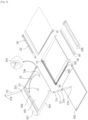
- FIG. 4 is an exploded perspective view of the roll-slide mobile terminal 100viewed in a front direction
- FIG. 5 is an exploded perspective view of the roll-slide mobile terminal 100viewed in a rear direction.
- the roll-slide mobile terminal 100 includes a first frame 101; a second frame 102 that can slide with respect to the first frame 101; and a third frame 103 that can slide in a first direction with respect to the second frame 102.
- the first frame 101 is provided as a basic frame of the roll-slide mobile terminal 100.
- One end of the flexible display unit 151 is coupled to the first frame 101 and a drive unit configured to guide the sliding movement of the second and third frames 102 and 103 is coupled to the first frame 101.
- the first frame 101 may include an edge portion 1011 provided in a predetermined edge area of the mobile terminal; and a middle portion 1013 formed in a plate shape.
- the middle portion 1013 and the edge portion 1011 may be integrally formed with each other or coupled to each other by an auxiliary member.
- the edge portion 1011 may be provided in a second-direction end of the roll-slide mobile terminal 100 and the middle portion 1013 may form a flat plate.
- the edge portion 1011 may be exposed outside and the middle portion 1013 may be covered by flexible display unit 151 and the second frame 102 not to be exposed outside.
- the first frame 101 may also include a side portion 1014 defining a lateral surface of the mobile terminal 100.
- the interface unit, the user input unit and a USIM card inserting slot may be arranged in the side portion 1014.
- An antenna can also be realized by using the side portion 1014.
- the second frame 102 is coupled to the first frame 101 and slides in the first or second direction.
- the second frame 102 may include a flat portion 1021 provided in a front surface of the middle portion 1013 of the first frame; and a bending portion 1022 that is bendable at the flat portion 1021 in the second direction.
- the bending portion 1022 may be insertedly bendable towards a rear surface of the middle portion 1013.
- FIG. 6 is a cross-sectional view taken along line A-A of FIG. 2
- FIG. 7 is a cross-sectional view taken along line B-B of FIG. 2
- the bending portion 1022 may be movable from the front surface towards the rear surface or vice versa based on the current state of the mobile terminal 100. Accordingly, the bending portion 1022 occupies a large area on the rear surface of the middle portion 1013 in the first state and a large area on the front surface of the middle portion 1013 in the second state.
- the flat portion 1021 may be always located on the front surface of the middle portion 1013 and the bending portion 1022 may be located on the front or rear surface of the middle portion 1013 based on the state of the mobile terminal.
- the bending portion 1022 may be configured of a plurality of support bars 1022a (see FIG. 5 ) extended in a third direction that is perpendicular to the first direction.
- the support bars 1022a may have a predetermined thickness or be bent to enhance the strength.
- the support bars may also be partially rolled in a ring shape and a hinge pin may be inserted in a rolled area to couple each two neighboring support bars 1022a.
- Each support bar 1022a may be rotatable with respect to its neighboring support bar and the hinge pin such that an angle between each two neighboring support bars 1022a is variable. Accordingly, the bending portion 1022 can be bent to overlap with the front surface and the rear surface.
- a slide portion 1023 may be further provided in one end of the bending portion 1022 to guide the sliding movement of the bending portion 1022.
- the slide portion 1023 may be one end of the bending portion such that it may move in the reverse direction, compared with the moving direction of the flat portion 1021.
- the flat portion 1021 moves in the first direction and the slide portion 1023 moves in the second direction.
- the bending portion 1022 may occupy a larger area on the front surface of the middle portion 1013.
- the flexible display unit 151 may have one end coupled to the first frame 101 and be extended in the first direction that is the reverse direction of the bending portion 1022 provided in the second frame 102.
- the flexible display unit 151 can be bent with rolling a first roller 105 coupled to the flat portion 1021 and then extended towards the rear surface of the flat portion 1021.
- the other end of the flexible display unit 151 is located on the rear surface of the flat portion 1021 and coupled to the third frame 103 so as to slide in the first and second directions.
- the third frame 103 and the flexible display unit 151 may be located on the front surface of the middle portion 1013 of the first frame 101 and the rear surface of the flat portion of the second frame 102, respectively.
- the slide portion 1023 located in the end of the bending portion 1022 may be located on the rear surface of the middle portion 1013.
- the layer structure in the first state may be configured of the first area of the flexible display unit 151.
- the flat portion 1021, the second area and the third frame 103 of the flexible display unit 151, the middle portion 1013 of the first frame, the bending portion 1022, the slide portion 1023 and the rear portion 1012 of the first frame defining the rear surface that is located in the most backward direction from the front surface.
- the flexible display unit 151 may include a display panel 151b configured to output an image; and a back plate 151c configured to support a rear surface of the display panel 151b.
- the display panel 151b may be a flexible image display device (e.g., OLED).
- the back plate 151c may be provided in the rear surface of the display p0anel 151b and a metal plate that is bendable together with the display panel 151b when it is bending, with a predetermined strength enough to support the display panel 151b.
- a groove may also be formed in a surface of the bending area of the back plate 151c in the third direction to naturally facilitate the bending, when the flexible display panel 151 is bending.
- the bending portion 1022 and the flexible display unit 151 are rolled in the reverse directions.
- the slide portion 1023 located in the end of the bending portion 1022 and the third frame 103 located in the end of the flexible display unit 151 moves in the reverse directions.
- the third frame 103 moves in the first direction and occupy a larger area of the front surface of the flexible display panel 151 provided in the mobile terminal 100.
- a first roller 105 may be further provided in the second frame 102 and configured to have the flexible display unit 151 rolled there around.
- a second roller 106 may be further provided in the first frame 101 and have the bending portion 1022 rolled there around. As shown in FIG. 6 , the second roller 106 may be located in a gap 1016 formed between the edge portion 1011 and the middle portion 1013 and rotatably coupled to the first frame 101.
- the first roller 105 and the second roller 106 may also be rotated in the reverse directions. When the second area of the flexible display unit 151 is moved in the first direction, the end of the bending portion 1022 also moves in the reverse direction (the second direction).
- the bending portion 1022 is advantageous so as to provide a structure that supports the expanded first area when the current state of the roll-slide mobile terminal 100 is changed into the second state. Unless the bending portion 1022 is provided as shown in FIG. 8 , an empty space might be generated in the rear surface of the first area of the flexible display unit 151 supported by the second frame 102 moving in the first direction and the empty space might cause corrugation in the flexible display unit 151.
- the second frame 102 may be configured to keep the height of one surface, that contacts with the rear surface of the flexible display unit 151, equal to the heights of the flat portion 1021 and the bending portions 1022 such that in the second state, the bending portion 1022 can support the first area supported by the flat portion 1021 in the first state.
- the bending portion 1022 may be movable along a rail 1015 formed in the first frame 101.
- the rail 1015 may be provided in both sides of the middle portion 1013 provided in the first frame 101 and have a corresponding width to the thickness of the bending portion 1022, with a groove shape extended in the first direction.
- the rail 1015 may be formed in an inner surface of the side portion defining the lateral surface of the first frame 101.
- the rail 1015 may be configured to guide the first-direction movement of the bending portion 1022 so as to prevent the deflection of the bending portion 1022.
- the drive unit may include a first drive unit 210 configured to guide the sliding movement of the third frame 103 coupled to the other end of the flexible display unit 151; and a second drive unit 220 configured to guide the sliding movement of the bending portion 1022.
- the first and second drive units may be arranged in both sides of the first frame 101 to realize the reverse-direction movements with respect to the first frame 101 coupled thereto.
- the first drive unit 210 may be arranged in a front surface of the first frame and the second drive unit 220 may be arranged in a rear surface of the first frame 101. Accordingly, the third frame 103 coupled to the first drive unit 210 may be located on the front surface of the first frame 101 and one end of the bending portion 1022 may be located on the rear surface of the first frame 101.
- the distance between the first and second areas of the flexible display unit 151 has to be narrow.
- the curvature of the bending flexible display unit 151 has to be very small disadvantageously. As the curvature of the bending flexible display unit 151 is getting smaller, the stress applied to the flexible display unit 151 is getting larger enough to heighten the possibility of damage to the flexible display unit 151.
- the roll-slide mobile terminal 100 may further include a third roller 107 configured to support the second area to bend towards the front surface so as to narrow the distance between the first area and the second area even though the flexible display unit 151 is bending along a gentle curve.
- a roll cover 1028 may be further provided to cover the third roller 107 and allow the user to pull the second frame 102 in the first direction.
- the roll cover 1028 shown in FIG. 6 may define the rear portion 1012 of the first frame 101 and the rear surface of the roll-slide mobile terminal 100. It is shown in the drawing that the roller cover 1028 is located on the rear surface of the roll-slide mobile terminal 100 but the roll cover may be extended even to the lateral surface to protect the curved area of the flexible display unit 151 rolled around the first roller 105.
- the flat portion 1021 of the second frame 102 is moving in the first direction and the slide portion 1023 of the second frame 102 is moving in the second direction.
- the flat portion 1021 located on the front surface of the middle portion 1013 of the first frame 101 and the slide portion 1023 located on the rear surface of the middle portion 1013 of the first frame 101 may move the same distance in the reverse directions, respectively.
- the first 210 may be provided to synchronize the moving distance of the flat portion 1021 and the moving distance of the slide portion so as to perform such symmetric movement stably.
- the first drive unit 210 may be configured to guide the flat portion 1021 and the slide portion 1023 to move the same distances in the reverse directions, respectively.
- a distance from the coupled center 211a to the end 211b may be equal to a distance from the coupled center 211a to the other end 211c.
- the end 211b and the other end 211c of the control bar 211 moves in arcs when the first control bar 211 is rotated such that the third-direction positions of the ends are changed based on the angle of the first control bar 211.
- a first slide slot 212 may be extended in the third direction from the slide portion 1023 to which the end of the first control bar is coupled and a second slide slot 213 may be extended in the third direction from the flat portion 1021 to which the other end 211c of the first control bar is coupled.
Landscapes
- Engineering & Computer Science (AREA)
- Signal Processing (AREA)
- Theoretical Computer Science (AREA)
- Computer Hardware Design (AREA)
- Physics & Mathematics (AREA)
- Human Computer Interaction (AREA)
- General Engineering & Computer Science (AREA)
- General Physics & Mathematics (AREA)
- Mathematical Physics (AREA)
- Telephone Set Structure (AREA)
Description
- Embodiments of the present disclosure relate to a roll-slide mobile terminal that has a flexible display and of which a screen is expandable.
- Terminals may be generally classified as mobile/portable terminals or stationary terminals. Mobile terminals may also be classified as handheld terminals or vehicle mounted terminals.
- A display device is equipped with functions of receiving, processing and displaying user-viewable images. The display device, for example, receives broadcasting selected by a user from broadcast signals broadcasted by a broadcasting station, splits video signals from the received signals, and displays the split video signals on a display.
- Recently, owing to the developments of broadcast and network technologies, functions of a display device have been considerably diversified and performance of the device has been improved correspondingly. Namely, the display device has been developed so as to provide a user with various contents as well as simply broadcasted contents. For example, the display device can provide game play, listening to music, Internet shopping, user-customized information and the like using various applications as well as programs received from broadcasting stations. In order to perform such extended functions, the display device is basically connected to other devices or a network using various communication protocols and can provide ubiquitous computing environments to a user. Namely, the display device has been evolved into a smart device that enables connectivity to a network and ubiquitous computing.
- Recently, a flexible display having sufficient elasticity to enable big deformation has been developed. The flexible display may be deformed to be rolled. A mobile terminal receives the rolled flexible display and may protrude the display to the outside of its body at a desired size. Therefore, the mobile terminal can have a more compact size in accordance with a use of the flexible display. Also, as the mobile terminal includes such a rollable display, the mobile terminal can be referred to as a rollable mobile terminal.
- In order to use the rollable mobile terminal, a user can eject the display from a body of the mobile terminal and at the same time the display can be extended to a size desired by the user. However, the display may be extended to various directions by the user, and relative alignment or arrangement of the display for the user may be varied depending on the extended direction. Therefore, in order to allow the user to view intended contents or screen, the mobile terminal needs to align contents or screen on the display in consideration of the varied display or relative alignment of the user. Moreover, the mobile terminal additionally needs to adjust the aligned contents in consideration of the extended direction and alignment.
-
KR 2106 0141255 A -
US 2009/149229 A1 discloses a sliding mechanism used for a portable electronic device with two or more housings. -
CN 108 259 649 A discloses a display including a plurality of support slats as a support mechanism moving around a chain wheel. -
US 2009/051830 A1 discloses a mobile terminal unit by which a pullout display to be pulled out from a body is utilized efficiently. The mobile terminal includes two rollers that are at the same housing and configured to maintain the tension of the display. -
US 2014/211399 A1 discloses a mobile device including housing parts that slide-engage relative to each other to extend and retract the device. The mobile device includes a plurality of rollers that are placed at the same housing and configured for maintaining the tension of the display. - Accordingly, an object of the present invention is to address the above-noted and other problems and provide a roll-slide mobile terminal capable of improving durability of a flexible display unit as a point where the flexible display unit is folded is limited to a specific position.
- Another object of the present invention is to provide a roll-slide mobile terminal including a support structure of a flexible display unit, in which the flexible display unit may stably be supported when it is extended.
- A further object of the present invention is to provide a roll-slide mobile terminal including a drive unit configured to guide the movements of a frame and a flexible display unit in communication which can prevent a corrugation generated in the flexible display unit separated from the frame, when the roll-slide mobile terminal is transited from a second state to a first state.
- A sill further object of the present invention is to provide a roll-slide mobile terminal that prevents a flexible display unit from being damaged by external impact at a side where the flexible display is folded.
- A roll-slide mobile terminal according to the present invention is set forth in claim 1. Preferred embodiments of the present invention are provided in dependent claims.
- The area of the front surface of the roll-slide mobile terminal that is occupied by the flexible display unit may be larger in the second state than the first state.
- The first frame may comprise an edge portion to which one end of the flexible display unit is coupled; and a middle portion in which the drive unit is provided.
- The second frame may comprise a flat portion provided on a front surface of the middle portion; and a bending portion provided in the second direction of the flat portion and configured to be partially located on a rear surface of the middle portion even when bending.
- The bending portion may comprise a plurality of support bars extended in a third direction that is perpendicular to the first direction and arranged in parallel with the second direction.
- The bending portion may slide along a rail formed in the first frame.
- The roll-slide mobile terminal further comprises a second roller coupled to the first frame and having the bending portion rolled there around.
- The first frame may comprise a gap formed between the edge portion and the middle portion, with the bending portion penetrating there through.
- The drive unit may comprise a first drive unit arranged in a rear surface of the middle portion and configured to guide the first and second direction movements of the second frame.
- The drive unit may comprise a first control bar having a center rotatably coupled to the first frame; a first slide slot extended from one end of the bending portion in a third direction that is perpendicular to the first direction and configured to insert a first slide projection, that is projected from one end of the first control bar, therein; and a second slide slot extended from the flat portion in the third direction and configured to insert a second slide projection, that is projected from the other end of the first control bar, therein.
- The first drive unit may further comprise a third slide slot formed in the first frame in an arc shape with respect the center of the first control bar, and the second slide projection may be coupled to the second slide slot through the third slide slot.
- The roll-slide mobile terminal may further comprise a securing slot extended from the first-direction end of the third slide slot in a third direction, wherein the second slide projection is located in the securing slot in the second state.
- The second drive unit may comprise a second drive unit provided in a front surface of the middle portion and configured to guide the first and second direction movements of the third frame.
- The second drive unit may comprise a fourth slide slot extended in a third direction that is perpendicular to the first direction and formed in the third frame; and a second control bar having one end rotataly coupled to the middle portion and a third slide projection projected from the other end, and the third slide projection may be inserted in the fourth slide slot to slide.
- The second drive unit may further comprise an elastic unit having one end fixed to the first or second frame and the other end connected with the second control bar or the third frame, and the elastic unit may provide a predetermined elasticity to pull the third frame in the second direction when the roll-slide mobile terminal is transited from the second state to the first state.
- The first frame may further comprise a rear portion configured to cover a rear surface of the bending portion.
- The roll-slide mobile terminal may further comprise a third roller provided adjacent to the first roller in the second direction and configured to support the flexible display unit located on the rear surface of the roll-slide mobile terminal.
- The flexible display unit may comprise a display panel; and a back plate configured to support a rear surface of the display panel and coupled to the first frame and the third frame.
- Since the roll-slide mobile terminal of the present invention does not limit a point where the flexible display unit is folded to a specific position, durability of the flexible display unit may be improved. Also, since the flexible display unit may stably be supported when it is extended, it is possible to minimize difficulty in a touch input. Also, the flexible display unit from may be prevented from being damaged by external impact at a side where the flexible display is folded.
- Further scope of applicability of the present invention will become apparent from the detailed description given hereinafter. However, it should be understood that the detailed description and specific examples, while indicating preferred embodiments of the invention, are given by illustration only, since various changes and modifications within the scope of the invention defined by the claims will become apparent to those skilled in the art from this detailed description.
- The present invention will become more fully understood from the detailed description given herein below and the accompanying drawings, which are given by illustration only, and thus are not limitative of the present invention, and wherein:
-
FIG. 1 is a block diagram of a role-slide mobile terminal according to an embodiment of the present disclosure; -
FIG. 2 is a perspective view illustrating a first state and a second state when a roll-slide mobile terminal according to an embodiment of the present invention is viewed at one side; -
FIG. 3 is a rear view illustrating a first state and a second state of a roll-slide mobile terminal according to an embodiment of the present invention; -
FIG. 4 is an exploded perspective view of the roll-slide mobile terminal according to an embodiment of the present invention, viewed in a front direction; -
FIG. 5 is an exploded perspective view of the roll-slide mobile terminal according to an embodiment of the present invention, viewed in a rear direction; -
FIG. 6 is a cross-sectional view taken along line A-A ofFIG. 2 ; -
FIG. 7 is a cross-sectional view taken along line B-B ofFIG. 2 ; -
FIG. 8 is a diagram illustrating a problem that could occur if there is no bending portion; -
FIG. 9 is a conceptual diagram illustrating the roll-slide mobile terminal according to an embodiment of the present invention; -
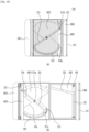
FIG. 10 is a diagram illustrating a first drive unit provided in the roll-slide mobile terminal; -
FIG. 11 is a diagram illustrating a second drive unit provided in the roll-slide mobile terminal; and -
FIGS. 12 and13 are diagrams illustrating another embodiment of the second drive unit provided in the roll-slide mobile terminal. - Description will now be given in detail according to exemplary embodiments disclosed herein, with reference to the accompanying drawings. For the sake of brief description with reference to the drawings, the same or equivalent components may be provided with the same reference numbers, and description thereof will not be repeated. In general, a suffix such as "module" and "unit" may be used to refer to elements or components. Use of such a suffix herein is merely intended to facilitate description of the specification, and the suffix itself is not intended to give any special meaning or function. The accompanying drawings are used to help easily understand various technical features and it should be understood that the embodiments presented herein are not limited by the accompanying drawings. As such, the present disclosure should be construed to extend to any alterations, equivalents and substitutes in addition to those which are particularly set out in the accompanying drawings.
- Although the terms first, second, etc. may be used herein to describe various elements, these elements should not be limited by these terms. These terms are generally only used to distinguish one element from another.
- When an element is referred to as being "connected with" another element, the element can be directly connected with the other element or intervening elements may also be present. In contrast, when an element is referred to as being "directly connected with" another element, there are no intervening elements present.
- A singular representation may include a plural representation unless it represents a definitely different meaning from the context. Terms such as "include" or "has" are used herein and should be understood that they are intended to indicate an existence of several components, functions or steps, disclosed in the specification, and it is also understood that greater or fewer components, functions, or steps may likewise be utilized.
-
FIG. 1 is a block diagram of a mobile terminal in accordance with the present disclosure. Themobile terminal 100 is shown having components such as awireless communication unit 110, aninput unit 120, asensing unit 140, anoutput unit 150, aninterface unit 160, amemory 170, acontroller 180, and apower supply unit 190. Implementing all of the illustrated components in The Fig. 1A is not a requirement, and that greater or fewer components may alternatively be implemented. - More specifically, the
wireless communication unit 110 typically includes one or more modules which permit communications such as wireless communications between themobile terminal 100 and a wireless communication system, communications between themobile terminal 100 and another mobile terminal, communications between themobile terminal 100 and an external server. Further, thewireless communication unit 110 typically includes one or more modules which connect themobile terminal 100 to one or more networks. - To facilitate such communications, the
wireless communication unit 110 includes one or more of abroadcast receiving module 111, amobile communication module 112, awireless Internet module 113, a short-range communication module 114, and alocation information module 115. Regarding thewireless communication unit 110, thebroadcast receiving module 111 is typically configured to receive a broadcast signal and/or broadcast associated information from an external broadcast managing entity via a broadcast channel. The broadcast channel may include a satellite channel, a terrestrial channel, or both. In some embodiments, two or morebroadcast receiving modules 111 may be utilized to facilitate simultaneously receiving of two or more broadcast channels, or to support switching among broadcast channels. - The
mobile communication module 112 can transmit and/or receive wireless signals to and from one or more network entities. Typical examples of a network entity include a base station, an external mobile terminal, a server, and the like. Such network entities form part of a mobile communication network, which is constructed according to technical standards or communication methods for mobile communications (for example, Global System for Mobile Communication (GSM), Code Division Multi Access (CDMA), CDMA2000 (Code Division Multi Access 2000), EV-DO (Enhanced Voice-Data Optimized or Enhanced Voice-Data Only), Wideband CDMA (WCDMA), High Speed Downlink Packet access (HSDPA), HSUPA (High Speed Uplink Packet Access), Long Term Evolution (LTE) , LTE-A (Long Term Evolution-Advanced), and the like). - Examples of wireless signals transmitted and/or received via the
mobile communication module 112 include audio call signals, video (telephony) call signals, or various formats of data to support communication of text and multimedia messages. - The
wireless Internet module 113 is configured to facilitate wireless Internet access. This module may be internally or externally coupled to themobile terminal 100. Thewireless Internet module 113 may transmit and/or receive wireless signals via communication networks according to wireless Internet technologies. - Examples of such wireless Internet access include Wireless LAN (WLAN), Wireless Fidelity (Wi-Fi), Wi-Fi Direct, Digital Living Network Alliance (DLNA), Wireless Broadband (WiBro), Worldwide Interoperability for Microwave Access (WiMAX), High Speed Downlink Packet Access (HSDPA), HSUPA (High Speed Uplink Packet Access), Long Term Evolution (LTE), LTE-A (Long Term Evolution-Advanced), and the like. The
wireless Internet module 113 may transmit/receive data according to one or more of such wireless Internet technologies, and other Internet technologies as well. - In some embodiments, when the wireless Internet access is implemented according to, for example, WiBro, HSDPA, HSUPA, GSM, CDMA, WCDMA, LTE, LTE-A and the like, as part of a mobile communication network, the
wireless Internet module 113 performs such wireless Internet access. As such, theInternet module 113 may cooperate with, or function as, themobile communication module 112. - The short-
range communication module 114 is configured to facilitate short-range communications. Suitable technologies for implementing such short-range communications include BLUETOOTHTM, Radio Frequency IDentification (RFID), Infrared Data Association (IrDA), Ultra-WideBand (UWB), ZigBee, Near Field Communication (NFC), Wireless-Fidelity (Wi-Fi), Wi-Fi Direct, Wireless USB (Wireless Universal Serial Bus), and the like. The short-range communication module 114 in general supports wireless communications between themobile terminal 100 and a wireless communication system, communications between themobile terminal 100 and anothermobile terminal 100, or communications between the mobile terminal and a network where another mobile terminal 100 (or an external server) is located, via wireless area networks. One example of the wireless area networks is a wireless personal area networks. - The
location information module 115 is generally configured to detect, calculate, derive or otherwise identify a position of the mobile terminal. As an example, thelocation information module 115 includes a Global Position System (GPS) module, a Wi-Fi module, or both. If desired, thelocation information module 115 may alternatively or additionally function with any of the other modules of thewireless communication unit 110 to obtain data related to the position of the mobile terminal. As one example, when the mobile terminal uses a GPS module, a position of the mobile terminal may be acquired using a signal sent from a GPS satellite. As another example, when the mobile terminal uses the Wi-Fi module, a position of the mobile terminal can be acquired based on information related to a wireless access point (AP) which transmits or receives a wireless signal to or from the Wi-Fi module. - The
input unit 120 includes acamera 121 for obtaining images or video, amicrophone 122, which is one type of audio input device for inputting an audio signal, and a user input unit 123 (for example, a touch key, a push key, a mechanical key, a soft key, and the like) for allowing a user to input information. Data (for example, audio, video, image, and the like) is obtained by theinput unit 120 and may be analyzed and processed bycontroller 180 according to device parameters, user commands, and combinations thereof. -
Cameras 121 may process image frames of still pictures or video obtained by image sensors in a video or image capture mode. The processed image frames can be displayed on thedisplay unit 151 or stored inmemory 170. In some cases, thecameras 121 may be arranged in a matrix configuration to permit a plurality of images having various angles or focal points to be input to themobile terminal 100. As another example, thecameras 121 may be located in a stereoscopic arrangement to acquire left and right images for implementing a stereoscopic image. - The
microphone 122 is generally implemented to permit audio input to themobile terminal 100. The audio input can be processed in various manners according to a function being executed in themobile terminal 100. If desired, themicrophone 122 may include assorted noise removing algorithms to remove unwanted noise generated in the course of receiving the external audio. - The
user input unit 123 is a component that permits input by a user. Such user input may enable thecontroller 180 to control operation of themobile terminal 100. Theuser input unit 123 may include one or more of a mechanical input element (for example, a key, a button located on a front and/or rear surface or a side surface of themobile terminal 100, a dome switch, a jog wheel, a jog switch, and the like), or a touch-sensitive input, among others. As one example, the touch-sensitive input may be a virtual key or a soft key, which is displayed on a touch screen through software processing, or a touch key which is located on the mobile terminal at a location that is other than the touch screen. Further, the virtual key or the visual key may be displayed on the touch screen in various shapes, for example, graphic, text, icon, video, or a combination thereof. - The
sensing unit 140 is typically implemented using one or more sensors configured to sense internal information of the mobile terminal, the surrounding environment of the mobile terminal, user information, and the like. For example,, thesensing unit 140 may alternatively or additionally include other types of sensors or devices, such as aproximity sensor 141 and anillumination sensor 142, a touch sensor, an acceleration sensor, a magnetic sensor, a G-sensor, a gyroscope sensor, a motion sensor, an RGB sensor, an infrared (IR) sensor, a finger scan sensor, a ultrasonic sensor, an optical sensor (for example, camera 121), amicrophone 122, a battery gauge, an environment sensor (for example, a barometer, a hygrometer, a thermometer, a radiation detection sensor, a thermal sensor, and a gas sensor, among others), and a chemical sensor (for example, an electronic nose, a health care sensor, a biometric sensor, and the like), to name a few. Themobile terminal 100 may be configured to utilize information obtained from sensingunit 140, and in particular, information obtained from one or more sensors of thesensing unit 140, and combinations thereof. - The
output unit 150 is typically configured to output various types of information, such as audio, video, tactile output, and the like. Theoutput unit 150 is shown having adisplay unit 151, anaudio output module 152, ahaptic module 153, and anoptical output module 154. Thedisplay unit 151 may have an inter-layered structure or an integrated structure with a touch sensor in order to facilitate a touch screen. The touch screen may provide an output interface between themobile terminal 100 and a user, as well as function as theuser input unit 123 which provides an input interface between themobile terminal 100 and the user. - The
audio output module 152 is generally configured to output audio data. Such audio data may be obtained from any of a number of different sources, such that the audio data may be received from thewireless communication unit 110 or may have been stored in thememory 170. The audio data may be output during modes such as a signal reception mode, a call mode, a record mode, a voice recognition mode, a broadcast reception mode, and the like. Theaudio output module 152 can provide audible output related to a particular function (e.g., a call signal reception sound, a message reception sound, etc.) performed by themobile terminal 100. Theaudio output module 152 may also be implemented as a receiver, a speaker, a buzzer, or the like. - A
haptic module 153 can be configured to generate various tactile effects that a user feels, perceive, or otherwise experience. A typical example of a tactile effect generated by thehaptic module 153 is vibration. The strength, pattern and the like of the vibration generated by thehaptic module 153 can be controlled by user selection or setting by the controller. For example, thehaptic module 153 may output different vibrations in a combining manner or a sequential manner. - An
optical output module 154 can output a signal for indicating an event generation using light of a light source. Examples of events generated in themobile terminal 100 may include message reception, call signal reception, a missed call, an alarm, a schedule notice, an email reception, information reception through an application, and the like. - The
interface unit 160 serves as an interface with various types of external devices that can be coupled to themobile terminal 100. Theinterface unit 160, for example, may include any of wired or wireless ports, external power supply ports, wired or wireless data ports, memory card ports, ports for connecting a device having an identification module, audio input/output (I/O) ports, video I/O ports, earphone ports, and the like. In some cases, themobile terminal 100 may perform assorted control functions associated with a connected external device, in response to the external device being connected to theinterface unit 160. - The
memory 170 is typically implemented to store data to support various functions or features of themobile terminal 100. For instance, thememory 170 may be configured to store application programs executed in themobile terminal 100, data or instructions for operations of themobile terminal 100, and the like. Some of these application programs may be downloaded from an external server via wireless communication. Other application programs may be installed within themobile terminal 100 at time of manufacturing or shipping, which is typically the case for basic functions of the mobile terminal 100 (for example, receiving a call, placing a call, receiving a message, sending a message, and the like). It is common for application programs to be stored in thememory 170, installed in themobile terminal 100, and executed by thecontroller 180 to perform an operation (or function) for themobile terminal 100. - The
controller 180 typically functions to control overall operation of themobile terminal 100, in addition to the operations associated with the application programs. Thecontroller 180 can provide or process information or functions appropriate for a user by processing signals, data, information and the like, which are input or output, or activating application programs stored in thememory 170. - To drive the application programs stored in the
memory 170, thecontroller 180 can be implemented to control a predetermined number of the components mentioned above in reference with FIG. 1A. Moreover, thecontroller 180 can be implemented to combinedly operate two or more of the components provided in themobile terminal 100 to drive the application programs. - The
power supply unit 190 can be configured to receive external power or provide internal power in order to supply appropriate power required for operating elements and components included in themobile terminal 100. Thepower supply unit 190 may include a battery, and the battery may be configured to be embedded in the terminal body, or configured to be detachable from the terminal body. - Some or more of the components may be operated cooperatively to embody an operation, control or a control method of the mobile terminal in accordance with embodiments of the present disclosure. Also, the operation, control or control method of the mobile terminal may be realized on the mobile terminal by driving of one or more application problems stored in the
memory 170. - Next,
FIG. 2 is a perspective view illustrating a first state and a second state when a roll-slide mobile terminal according to an embodiment of the present invention is viewed at one side, andFIG. 3 is a rear view illustrating a first state and a second state of a roll-slide mobile terminal according to an embodiment of the present invention. In particular,FIGS. 2(a) and3(a) illustrate a first state of the roll-slidemobile terminal 100 according to one embodiment of the present invention, andFIGS. 2(b) and3(b) illustrate a second state of a roll-slidemobile terminal 100 according to one embodiment of the present invention. - As shown, the roll-slide
mobile terminal 100 of the first state has a size smaller than that of the roll-slidemobile terminal 100 of the second state in a first direction. In the roll-slidemobile terminal 100 of the second state, the size of the first direction is extended and a size of adisplay unit 151 arranged on a front surface becomes greater than the first state. In addition, a direction along which the roll-slidemobile terminal 100 is extended is referred to as a first direction, a direction along which the roll-slidemobile terminal 100 is contracted to be shifted from the second state to the first state is referred to as a second direction, and a direction vertical to the second direction is referred to as a third direction. - In a first state of the roll-slide
mobile terminal 100 according to an embodiment of the present invention like a bar-type mobile terminal, a screen is expanded and changed into a second state. In the second state, the area of thedisplay unit 151 arranged in the front surface is expanded in a first direction and the area of the display unit arranged in the rear surface as shown inFIG. 3 (b) is reduced. In other words, the display unit located in the rear surface in the first state is moved towards the front surface in the second state. For easy and convenient description sake, the area of thedisplay unit 151 that is located in the front surface of the roll-slidemobile terminal 100 is defined as the first area and the area located in the rear surface of the roll-slidemobile terminal 100 is defined as the second area. The first area and the second can be changed based on the current state of the roll-slidemobile terminal 100. - In this way, a
flexible display unit 151 which is bent may be used as the display unit such that the position of the display unit can be varied. In more detail, the flexible display means a display, which is manufactured on a thin and flexible substrate capable of being curved, bent, folded, twisted or rolled like a paper, and is lightweight and robust not to be easily broken while maintaining characteristics of the existing flat panel display. - Also, an electronic paper is based on a display technique to which a feature of a general ink is applied, and is different from the existing flat panel display in that it uses reflective light. The electronic paper can change information by using electrophoresis that uses a twist ball or capsule.
- When the
flexible display unit 151 is not deformed (for example, the state that theflexible display unit 151 has an infinite curvature radius, hereinafter, referred to as base state), a display area of theflexible display unit 151 becomes a plane. In a state (for example, the state having a finite curvature radius, hereinafter, referred to as a deformation state) deformed by an external force from the base state, the display area has a curved surface. As shown, information displayed in the deformation state may be visual information output to the curved surface. This visual information is implemented as luminescence of unit sub-pixels arranged in a matrix arrangement is controlled independently. The unit sub-pixel means a minimum unit for implementing one color. - In addition, the
flexible display unit 151 can be arranged in a bent state (for example, the state bent in a vertical or horizontal direction) not a flat state in the base state. In this instance, if an external force is applied to theflexible display unit 151, theflexible display unit 151 can be deformed in a flat state (or less bent state) or a more bent state. - Further, the
flexible display unit 151 may implement a flexible touch screen in combination with a touch sensor. If a touch is performed for a flexible touch screen, thecontroller 180 can perform a control corresponding to such a touch input. The flexible touch screen may be configured to sense a touch input even in the deformation state as well as the base state. - In addition, the touch sensor senses a touch (or touch input) applied to the touch screen by using at least one of various touch modes such as a resistive film mode, a capacitance mode, an infrared mode, an ultrasonic mode, and a magnetic field mode. As an example, the touch sensor can be configured to convert a change of a pressure applied to a specific portion of the touch screen or a change of capacitance occurring in the specific portion to an electric input signal. The touch sensor can also be configured to allow a touch target, which performs a touch on the touch screen, to detect a touch position, a touch area, a touch pressure and touch capacitance on the touch sensor.
- Further, the roll-slide
mobile terminal 100 according to this modified embodiment may include a deformation sensing mechanism capable of sensing deformation of theflexible display unit 151. The deformation sensing mechanism may be included in thesensing unit 140. - The deformation sensing mechanism may be provided in the
flexible display unit 151 or a case 201 to sense information related to deformation of theflexible display unit 151. In this instance, the information related to deformation may include a direction of theflexible display unit 151 which is modified, a modified level, a modified position, a modified time and restored acceleration of the deformedflexible display unit 151. In addition, the information related to deformation may include various kinds of information to be sensed by bending of theflexible display unit 151. - Also, the
controller 180 can modify information displayed on theflexible display unit 151 or generate a control signal for controlling functions of the roll-slidemobile terminal 100, based on the information related to deformation of theflexible display unit 151 sensed by the deformation sensing means. State deformation of theflexible display unit 151 is not limited to deformation caused by an external force. For example, when theflexible display unit 151 has the first state, the first state can be modified to the second state by a command of a user or an application. In this way, in order that theflexible display unit 151 is modified without external force, theflexible display unit 151 may include a driving unit. - In addition, the
flexible display unit 151 may be bent 180 degrees. Some area of theflexible display unit 151 may also be positioned on the front surface and the other area may be positioned on the rear surface of the roll-slidemobile terminal 100. The overall area of theflexible display unit 151 is fixed such that the extent of the area located in the rear surface (the second area) may decrease if the extent of the area located in the front surface (the first area) increases. - Next,
FIG. 4 is an exploded perspective view of the roll-slide mobile terminal 100viewed in a front direction, andFIG. 5 is an exploded perspective view of the roll-slide mobile terminal 100viewed in a rear direction. As shown inFIGS. 2 and3 , the roll-slidemobile terminal 100 includes afirst frame 101; asecond frame 102 that can slide with respect to thefirst frame 101; and athird frame 103 that can slide in a first direction with respect to thesecond frame 102. - The
first frame 101 is provided as a basic frame of the roll-slidemobile terminal 100. One end of theflexible display unit 151 is coupled to thefirst frame 101 and a drive unit configured to guide the sliding movement of the second andthird frames first frame 101. As shown inFIG. 4 , thefirst frame 101 may include anedge portion 1011 provided in a predetermined edge area of the mobile terminal; and amiddle portion 1013 formed in a plate shape. Themiddle portion 1013 and theedge portion 1011 may be integrally formed with each other or coupled to each other by an auxiliary member. Theedge portion 1011 may be provided in a second-direction end of the roll-slidemobile terminal 100 and themiddle portion 1013 may form a flat plate. Theedge portion 1011 may be exposed outside and themiddle portion 1013 may be covered byflexible display unit 151 and thesecond frame 102 not to be exposed outside. - As shown in
FIG. 4 , thefirst frame 101 may also include aside portion 1014 defining a lateral surface of themobile terminal 100. The interface unit, the user input unit and a USIM card inserting slot may be arranged in theside portion 1014. An antenna can also be realized by using theside portion 1014. - Further, the
second frame 102 is coupled to thefirst frame 101 and slides in the first or second direction. As shown, thesecond frame 102 may include aflat portion 1021 provided in a front surface of themiddle portion 1013 of the first frame; and abending portion 1022 that is bendable at theflat portion 1021 in the second direction. The bendingportion 1022 may be insertedly bendable towards a rear surface of themiddle portion 1013. - Next,
FIG. 6 is a cross-sectional view taken along line A-A ofFIG. 2 , andFIG. 7 is a cross-sectional view taken along line B-B ofFIG. 2 . The bendingportion 1022 may be movable from the front surface towards the rear surface or vice versa based on the current state of themobile terminal 100. Accordingly, the bendingportion 1022 occupies a large area on the rear surface of themiddle portion 1013 in the first state and a large area on the front surface of themiddle portion 1013 in the second state. Theflat portion 1021 may be always located on the front surface of themiddle portion 1013 and the bendingportion 1022 may be located on the front or rear surface of themiddle portion 1013 based on the state of the mobile terminal. - The bending
portion 1022 may be configured of a plurality ofsupport bars 1022a (seeFIG. 5 ) extended in a third direction that is perpendicular to the first direction. The support bars 1022a may have a predetermined thickness or be bent to enhance the strength. The support bars may also be partially rolled in a ring shape and a hinge pin may be inserted in a rolled area to couple each two neighboringsupport bars 1022a. Eachsupport bar 1022a may be rotatable with respect to its neighboring support bar and the hinge pin such that an angle between each two neighboringsupport bars 1022a is variable. Accordingly, the bendingportion 1022 can be bent to overlap with the front surface and the rear surface. - A
slide portion 1023 may be further provided in one end of the bendingportion 1022 to guide the sliding movement of the bendingportion 1022. Aslide slot 212, to which oneend 211b of a first control bar of the first drive unit which will be described later is coupled, is formed in theslide portion 1023 such that theslide portion 1023 can guide the sliding movement of thesecond frame 102. - The
slide portion 1023 may be one end of the bending portion such that it may move in the reverse direction, compared with the moving direction of theflat portion 1021. When the first state is changed into the second state in the roll-slidemobile terminal 100, theflat portion 1021 moves in the first direction and theslide portion 1023 moves in the second direction. At this time, the bendingportion 1022 may occupy a larger area on the front surface of themiddle portion 1013. - In addition, the
flexible display unit 151 may have one end coupled to thefirst frame 101 and be extended in the first direction that is the reverse direction of the bendingportion 1022 provided in thesecond frame 102. Theflexible display unit 151 can be bent with rolling afirst roller 105 coupled to theflat portion 1021 and then extended towards the rear surface of theflat portion 1021. The other end of theflexible display unit 151 is located on the rear surface of theflat portion 1021 and coupled to thethird frame 103 so as to slide in the first and second directions. - Referring to
FIGS. 6 and7 , thethird frame 103 and theflexible display unit 151 may be located on the front surface of themiddle portion 1013 of thefirst frame 101 and the rear surface of the flat portion of thesecond frame 102, respectively. Theslide portion 1023 located in the end of the bendingportion 1022 may be located on the rear surface of themiddle portion 1013. - Referring to
FIG. 6 , the layer structure in the first state may be configured of the first area of theflexible display unit 151. Theflat portion 1021, the second area and thethird frame 103 of theflexible display unit 151, themiddle portion 1013 of the first frame, the bendingportion 1022, theslide portion 1023 and therear portion 1012 of the first frame defining the rear surface that is located in the most backward direction from the front surface. - Referring to
FIG. 7 , one end of theflexible display unit 151 coupled to themiddle portion 1013 and theedge portion 1011 of thefirst frame 101, therear portion 1012 and thesecond roller 106 having the bendingportion 1022 rolled there around are located on the left side shown in the drawing in the second state. Theflat portion 1021 of the second frame, thefirst roller 105 and thethird roller 107, and thethird frame 103 move to right side. - The
flexible display unit 151 may include a display panel 151b configured to output an image; and aback plate 151c configured to support a rear surface of the display panel 151b. - The display panel 151b may be a flexible image display device (e.g., OLED). The
back plate 151c may be provided in the rear surface of the display p0anel 151b and a metal plate that is bendable together with the display panel 151b when it is bending, with a predetermined strength enough to support the display panel 151b. - Further, the
back plate 151c and the display panel 151b may be bonded to each other, using an adhesive material. Examples of the adhesive material may include a double-sided tape (e.g., OCA) that is extendible in a preset range such as a foam material. Accordingly, the adhesive material may offset a slip phenomenon that might be caused by a difference between the curvature radius of theback plate 151c and that of the display panel 151b. - A groove may also be formed in a surface of the bending area of the
back plate 151c in the third direction to naturally facilitate the bending, when theflexible display panel 151 is bending. In addition, the bendingportion 1022 and theflexible display unit 151 are rolled in the reverse directions. When the current state of the roll-slide mobile terminal is changed into the first state or second state, theslide portion 1023 located in the end of the bendingportion 1022 and thethird frame 103 located in the end of theflexible display unit 151 moves in the reverse directions. Specifically, when the first state is changed into the second state, thethird frame 103 moves in the first direction and occupy a larger area of the front surface of theflexible display panel 151 provided in themobile terminal 100. - A
first roller 105 may be further provided in thesecond frame 102 and configured to have theflexible display unit 151 rolled there around. Also, asecond roller 106 may be further provided in thefirst frame 101 and have the bendingportion 1022 rolled there around. As shown inFIG. 6 , thesecond roller 106 may be located in agap 1016 formed between theedge portion 1011 and themiddle portion 1013 and rotatably coupled to thefirst frame 101. Thefirst roller 105 and thesecond roller 106 may also be rotated in the reverse directions. When the second area of theflexible display unit 151 is moved in the first direction, the end of the bendingportion 1022 also moves in the reverse direction (the second direction). - Further, the bending
portion 1022 is advantageous so as to provide a structure that supports the expanded first area when the current state of the roll-slidemobile terminal 100 is changed into the second state. Unless the bendingportion 1022 is provided as shown inFIG. 8 , an empty space might be generated in the rear surface of the first area of theflexible display unit 151 supported by thesecond frame 102 moving in the first direction and the empty space might cause corrugation in theflexible display unit 151. - Even if a support structure is provided in the rear surface of the
second frame 102, the empty space as large as the thickness of thesecond frame 102 might be generated to cause deflection in the display unit. accordingly, as shown inFIG. 9 , thesecond frame 102 may be configured to keep the height of one surface, that contacts with the rear surface of theflexible display unit 151, equal to the heights of theflat portion 1021 and thebending portions 1022 such that in the second state, the bendingportion 1022 can support the first area supported by theflat portion 1021 in the first state. - In addition, the bending
portion 1022 may be movable along arail 1015 formed in thefirst frame 101. As shown inFIG. 4 , therail 1015 may be provided in both sides of themiddle portion 1013 provided in thefirst frame 101 and have a corresponding width to the thickness of the bendingportion 1022, with a groove shape extended in the first direction. Therail 1015 may be formed in an inner surface of the side portion defining the lateral surface of thefirst frame 101. Therail 1015 may be configured to guide the first-direction movement of the bendingportion 1022 so as to prevent the deflection of the bendingportion 1022. - The
first frame 101 may further include arear portion 1012 defining an external design of the rear surface as shown inFIG. 3 . Therear portion 1012 may form the external rear design of the roll-slidemobile terminal 100 and cover the drive unit and the bendingportion 1022 of thesecond frame 102 not to expose the drive unit to the rear surface in the first state. - The drive unit may include a
first drive unit 210 configured to guide the sliding movement of thethird frame 103 coupled to the other end of theflexible display unit 151; and a second drive unit 220 configured to guide the sliding movement of the bendingportion 1022. The first and second drive units may be arranged in both sides of thefirst frame 101 to realize the reverse-direction movements with respect to thefirst frame 101 coupled thereto. Thefirst drive unit 210 may be arranged in a front surface of the first frame and the second drive unit 220 may be arranged in a rear surface of thefirst frame 101. Accordingly, thethird frame 103 coupled to thefirst drive unit 210 may be located on the front surface of thefirst frame 101 and one end of the bendingportion 1022 may be located on the rear surface of thefirst frame 101. - To locate the other end of the
flexible display unit 151 on the front surface of thefirst frame 101, the distance between the first and second areas of theflexible display unit 151 has to be narrow. In other words, to space the first and second areas a distance as far as the thickness of theflat portion 1021 of thesecond frame 102, the curvature of the bendingflexible display unit 151 has to be very small disadvantageously. As the curvature of the bendingflexible display unit 151 is getting smaller, the stress applied to theflexible display unit 151 is getting larger enough to heighten the possibility of damage to theflexible display unit 151. - Accordingly, the roll-slide
mobile terminal 100 may further include athird roller 107 configured to support the second area to bend towards the front surface so as to narrow the distance between the first area and the second area even though theflexible display unit 151 is bending along a gentle curve. - A
roll cover 1028 may be further provided to cover thethird roller 107 and allow the user to pull thesecond frame 102 in the first direction. Theroll cover 1028 shown inFIG. 6 may define therear portion 1012 of thefirst frame 101 and the rear surface of the roll-slidemobile terminal 100. It is shown in the drawing that theroller cover 1028 is located on the rear surface of the roll-slidemobile terminal 100 but the roll cover may be extended even to the lateral surface to protect the curved area of theflexible display unit 151 rolled around thefirst roller 105. - When the roll-slide
mobile terminal 100 is transited from the first state into the second state, theflat portion 1021 of thesecond frame 102 is moving in the first direction and theslide portion 1023 of thesecond frame 102 is moving in the second direction. Theflat portion 1021 located on the front surface of themiddle portion 1013 of thefirst frame 101 and theslide portion 1023 located on the rear surface of themiddle portion 1013 of thefirst frame 101 may move the same distance in the reverse directions, respectively. The first 210 may be provided to synchronize the moving distance of theflat portion 1021 and the moving distance of the slide portion so as to perform such symmetric movement stably. Thefirst drive unit 210 may be configured to guide theflat portion 1021 and theslide portion 1023 to move the same distances in the reverse directions, respectively. - Next,
FIG. 10 is a diagram illustrating thefirst drive unit 210 provided in the roll-slidemobile terminal 100. In particular,FIG. 10 (a) is a sectional diagram along C-C ofFIG. 6 andFIG. 10 (b) is a sectional diagram along D-D ofFIG. 7 as a view illustrating a state where only therear portion 1012 of thefirst frame 101 is removed from a state viewing the rear surface of themobile terminal 100 ofFIG. 3 . In the first state, thefirst drive unit 210 is hidden by the bendingportion 1022 of thesecond frame 102 and is shown as a dotted line. - The
first drive unit 210 includes afirst control bar 211 provided in a rear surface of themiddle portion 1013 provided in thefirst frame 101. Thefirst control bar 211 has acenter 211a rotatably coupled to a center of themiddle portion 1013 of thefirst frame 101. Oneend 211b of the first control bar is coupled to theslide portion 1023 of thesecond frame 102 and theother end 211c is coupled to theflat portion 1021. When the first state is transited into the second state in themobile terminal 100, theflat portion 1021 is moving from the front surface of themiddle portion 1013 in the first direction and theslide portion 1023 is moving from the rear surface of themiddle portion 1013 in the second direction. In other words, the moving directions of theflat portion 1021 and theslide portion 1023 are reverse such that thefirst controller bar 211 is rotatable on thecenter 211a rotatably coupled to themiddle portion 1013. - In the
control bar 211, a distance from the coupledcenter 211a to theend 211b may be equal to a distance from the coupledcenter 211a to theother end 211c. Theend 211b and theother end 211c of thecontrol bar 211 moves in arcs when thefirst control bar 211 is rotated such that the third-direction positions of the ends are changed based on the angle of thefirst control bar 211. To compensate a difference between the rotational movement and the linear movement, afirst slide slot 212 may be extended in the third direction from theslide portion 1023 to which the end of the first control bar is coupled and asecond slide slot 213 may be extended in the third direction from theflat portion 1021 to which theother end 211c of the first control bar is coupled. - In addition, the
first slide slot 212 is coupled to thefirst control bar 211 towards the front surface and thesecond slide slot 213 is coupled thereto towards the rear surface. Thefirst slide slot 212 and thesecond slide slot 213 may be as long as a distance where thefirst control bar 211 moves in the third direction when the first state is transited into the second state. - As the
flat portion 1021 is directed to the front surface of the middle frame, athird slide slot 214 may be formed in themiddle potion 1013 in an arc shape as shown inFIG. 10 (b) , so as to couple theflat portion 1021 and thefirst control bar 211 to each other. Theother end 211c of the first control bar may be inserted in thesecond slide slot 213 of theflat portion 1021 through thethird slide slot 214. - The
third slide slot 214 may further include a securingslot 225a (seeFIG. 12 ) extended from the area, where theother end 211c of the first control bar is located in the second state, in the third direction as shown inFIG. 10 (a) . The securingslot 225a restricts the rotation of thefirst control bar 211 to secure the second state transited by the user pulling thesecond frame 102 in the first direction. A ribbon-shapedgroove 216 may be formed in themiddle portion 1013 to guide the rotation of thefirst control bar 211 as shown inFIG. 10 (b) . - Next,
FIG. 11 is a diagram illustrating the second drive unit 220 provided in the roll-slidemobile terminal 100. While theflat portion 1021 of thesecond frame 102 is moving in the first direction, the first area of theflexible display unit 151 is expanded and thethird frame 103 to which the other end of theflexible display unit 151 is coupled is moving in the first direction. The second drive unit 220 may be configured to guide the first-direction movement of thethird frame 103. The second drive unit may include asecond control bar 221 and afourth slide slot 222. - In particular,
FIG. 11 (a) is a sectional diagram along E-E ofFIG. 6 andFIG. 11 (b) is a sectional diagram along F-F illustrating only a member located towards the front surface of themiddle portion 1013. Oneend 221a of the second control bar is rotatably coupled to themiddle portion 1013 and theother end 221b thereof is coupled to thefourth slide slot 222 formed in thethird frame 103. When thesecond control bar 221 is rotated on theend 221a coupled to themiddle portion 1013, theother end 221b is moving in arcs. During the moving of theother end 221b of the second control bar, only the first and second direction moving may affect thethird frame 103 and the third direction moving may use thefourth slide slot 222 extended in the third direction for the offsetting of the movement. When a state ofFIG. 11 (a) is transited to a state ofFIG. 11 (b) or vice versa in thesecond control bar 221, theother end 221b is moving along thefourth slide slot 222 formed in thethird frame 103. - When the first state is transited into the second state, the user pulls the second control bar in a direction where the first and
second frames flat portion 1021 of thesecond frame 102 moves in the first direction, while theslide portion 1023 and thethird frame 103 moves in the second direction and the first direction, respectively. At this time, the state shown inFIG. 11 (a) is naturally transited intoFIG. 11 (b) state in thesecond control bar 221. - In contrast, when user pushes the
second frame 102 to thefirst frame 101. In other words, pushing thesecond frame 102 in the second direction, the second area of theflexible display unit 151 has to be wide and thethird frame 103 has to move in the second direction accordingly. When theflat portion 1021 of thesecond frame 102 moves in the second direction, thefirst control bar 211 is rotated as shown inFIG. 10(a) from a state shown inFIG. 10 (b) . At this time, theother 3end 211c of the first control bar is rotated in the second direction to pull theother end 221b of the second control bar. - Specifically, the force used in pulling the
second control bar 221 in the second direction is needed to move it in the direction where the second area of theflexible display unit 151 is getting wide when the first state is transited to the second state. The sliding movement of thethird frame 103 could be facilitated by using electric power of a motor. However, one embodiment of the present invention may provide anelastic unit 225 configured to support the rotational movement of thesecond control bar 221, without the motor. - As shown in
FIG. 11 , the elastic unit according to the embodiment may be acoil spring 225 having oneend 225a coupled to thefirst frame 101 and theother end 225b coupled to thesecond control bar 221. To make the coil spring tensile, a predetermined force is needed and a tensile spring may be used for that tensile. When the user pulls thesecond frame 102 in the first direction to transit the first state into the second state, thethird frame 103 also moves in the first direction and the coil spring is lengthened to be given tension. - Once the
first control bar 211 is secured to the securingslot 214a mentioned above, the second state is secured and thecoil spring 225 is secured in a state of being tensioned. When the user transits the second state into the first state of the roll-slidemobile terminal 100 by pushing thesecond frame 102 in the second direction, thefirst control bar 211 is separated from the securingslot 214a and rotated along thethird slide slot 214. Hence, thesecond control bar 221 is rotated by the elasticity of theelastic unit 225 as shown inFIG. 11 (b) and FIG. 11 (c) to move thethird frame 103 in the second direction. - Next,
FIGS. 12 and13 are diagrams illustrating another embodiment of the second drive unit 220 provided in the roll-slidemobile terminal 100. Theelastic unit 225 of the second drive unit 220 may be configured to apply an elastic force to rotate thesecond control bar 221 when the mobile terminal is switched from the second state into the first state. - Rather than the above-noted
coil spring 225, atorsion spring 225 may be used as shown inFIG. 12 . Thetorsion spring 225 may have one metal fan-shapedend 225a and theother end 225b that form a preset angle, with a coil wounded around the spring between the ends, and be configured to provide a predetermined elasticity applied to restore the angle between the ends in a preset angle. The ends of thetorsion spring 225 are arranged at a preset angle in the first state of themobile terminal 100. One end is coupled to thefirst frame 101 and the other end is coupled to thesecond control bar 221. When the user pushes thesecond frame 102 in the second direction in the second state of the mobile terminal, thefirst control bar 211 is released from the securingslot 214a and thesecond control bar 221 is rotated by the elasticity of thetorsion spring 225. After that, thethird frame 103 is moved in the second direction and the roll-slidemobile terminal 100 is transited into the first state as shown inFIG. 12 (b) . -
FIG. 13 shows one embodiment using acompound spring 225. Theelastic unit 225 is not limited to the specific types such as thecoil spring 225 or thetorsion spring 225 but it may be diverse types. As shown inFIG. 13 , one end the other end of theelastic unit 225 may be coupled to thesecond frame 102 and thethird frame 103, respectively, as shown inFIG. 13 . In other words, theelastic unit 225 may be the member configured to provide a predetermined force for moving thethird frame 103 with respect to thesecond frame 102 or thefirst frame 101 in the second direction such that oneend 225a thereof may be coupled to thefirst frame 101 or thesecond frame 102 and theother end 225b thereof may be coupled to thesecond control bar 221 or thethird frame 103. - As described above, since the roll-slide mobile terminal of the present invention does not limit a point where the
flexible display unit 151 is folded to a specific position, the durability of theflexible display unit 151 is improved. Also, since theflexible display unit 151 can stably be supported when it is extended, it is possible to minimize the difficulty in a touch input. Further, theflexible display unit 151 can be prevented from being damaged by external impact at the side where theflexible display unit 151 is folded. - It will be apparent to those skilled in the art that the present specification can be embodied in other specific forms . Thus, the above embodiments are to be considered in all respects as illustrative and not restrictive. The scope of the present invention should be determined by reasonable interpretation of the appended claims.
Claims (14)
- A roll-slide mobile terminal comprising:a first frame (101);a second frame (102) configured to slide with respect to the first frame (101) in a first direction along which the roll-slide mobile terminal is extended or a second direction opposite the first direction;a first roller (105) provided in a first end of the second frame (102) in the first direction;a second roller (106) provided at the first frame (101);a third frame (103) provided in a rear surface of the second frame (102);a flexible display unit (151) rolled around the first roller and having a first end fixed to the first frame (101) and a second end coupled to the third frame (103) and placed on the rear surface; anda drive unit (210, 220) configured to guide a sliding movement of the second frame (102) with respect to the first frame (101) in the first direction to transition the roll-slide mobile terminal from a first state to a second state , and to guide a sliding movement of the second frame (102) with respect to the first frame (101) in the second direction to transition the roll-slide mobile terminal from the second state to the first state,wherein the second frame (102) comprises:a flat portion (1021) on a rear surface of the flexible display unit; anda bending portion (1022) rolled around the second roller (106) and having a front bending portion located in the second direction of the flat portion and a rear bending portion, andwherein the third frame (103) is configured to slide with respect to the flat portion (1021) of the second frame (102) in the first direction when the flat portion (1021) of the second frame (102) moves in the first direction and the rear bending portion moves in the second direction.
- The roll-slide mobile terminal of claim 1, wherein the first frame (101) comprises:an edge portion (1011) to which the first end of the flexible display unit (151) is coupled; anda middle portion (1012) in which the drive unit (200) is provided.
- The roll-slide mobile terminal of claim 2, wherein the rear bending portion is located on a rear surface of the middle portion.
- The roll-slide mobile terminal of one of claims 1 to 3, wherein the bending portion (1022) comprises a plurality of support bars (1022a) extended in a third direction that is perpendicular to the first direction and arranged in parallel with the second direction.
- The roll-slide mobile terminal of one of claims 1 to 4, wherein the bending portion (1022) is configured to slide along a rail (1015) formed in the first frame (101).
- The roll-slide mobile terminal of one of claim 2 to 5, wherein the first frame (101) comprises a gap formed between the edge portion (1011) and the middle portion (1012), with the bending portion (1022) penetrating there through.
- The roll-slide mobile terminal of one of claim 2 to 6, wherein the drive unit comprises a first drive unit (210) arranged in a rear surface of the middle portion and configured to guide movements of the first frame (101) with respect to the second frame (102).
- The roll-slide mobile terminal of one of claim 1 to 7, wherein the first drive unit (210) comprises:a first control bar (211) having a center rotatably coupled to the first frame;a first slide slot (212) extended from one end of the bending portion (1022) in a third direction perpendicular to the first direction and configured to receive a first slide projection projected from one end (211a) of the first control bar (211); anda second slide slot (213) extended from the flat portion in the third direction and configured to receive a second slide projection projected from the other end (221b) of the first control bar (211).
- The roll-slide mobile terminal of claim 8, wherein the first drive unit further comprises:a third slide slot (214) formed in the first frame in an arc shape with respect the center of the first control bar (211), andwherein the second slide projection is coupled to the second slide slot (213) through the third slide slot.
- The roll-slide mobile terminal of claim 9, further comprising:a securing slot (214a) extended from an end of the third slide slot (214) in the third direction,wherein the second slide projection is located in the securing slot (214a) in the second state.
- The roll-slide mobile terminal of claim 1, wherein the drive unit further comprises a second drive unit (220) provided in a front surface of the middle portion and configured to guide the movements of the first frame (101) with respect to the second frame (102).
- The roll-slide mobile terminal of claim 11, wherein the second drive unit comprises:a fourth slide slot (222) extended in the third direction and formed in the third frame; anda second control bar (221) having one end (221a) rotatably coupled to the middle portion and a third slide projection projected from the other end (221b), andwherein the third slide projection is inserted in the fourth slide slot (222) to slide the second control bar (221) with respect to the third frame (103) in the third direction.
- The roll-slide mobile terminal of claim 12, wherein the second drive unit (220) further comprises an elastic unit (225) having one end fixed to the first or second frame (102) and the other end connected with the second control bar (221) or the third frame (103), and
wherein the elastic unit (225) provides a predetermined elasticity to pull the third frame (103) in the second direction when the roll-slide mobile terminal is transited from the second state to the first state. - The roll-slide mobile terminal of one of claim 1 to 13, further comprising:
a third roller (107) provided adjacent to the first roller in the second direction and configured to support the flexible display unit (151) located on the rear surface of the roll-slide mobile terminal.
Applications Claiming Priority (2)
| Application Number | Priority Date | Filing Date | Title |
|---|---|---|---|
| KR1020190048567A KR102859226B1 (en) | 2019-04-25 | 2019-04-25 | Roll-slide mobile terminal |
| PCT/KR2019/010313 WO2020218681A1 (en) | 2019-04-25 | 2019-08-13 | Roll-slide mobile terminal |
Publications (3)
| Publication Number | Publication Date |
|---|---|
| EP3959865A1 EP3959865A1 (en) | 2022-03-02 |
| EP3959865A4 EP3959865A4 (en) | 2023-01-11 |
| EP3959865B1 true EP3959865B1 (en) | 2025-07-02 |
Family
ID=71993812
Family Applications (1)
| Application Number | Title | Priority Date | Filing Date |
|---|---|---|---|
| EP19926535.6A Active EP3959865B1 (en) | 2019-04-25 | 2019-08-13 | Roll-slide mobile terminal |
Country Status (4)
| Country | Link |
|---|---|
| US (1) | US10742784B1 (en) |
| EP (1) | EP3959865B1 (en) |
| KR (1) | KR102859226B1 (en) |
| WO (1) | WO2020218681A1 (en) |
Families Citing this family (44)
| Publication number | Priority date | Publication date | Assignee | Title |
|---|---|---|---|---|
| USD915320S1 (en) * | 2018-03-15 | 2021-04-06 | Huawei Technologies Co., Ltd. | Mobile phone |
| KR102707459B1 (en) * | 2019-07-29 | 2024-09-20 | 엘지전자 주식회사 | Rollable display device |
| KR102281347B1 (en) * | 2019-09-27 | 2021-07-23 | 엘지전자 주식회사 | Mobile terminal |
| CN110634408B (en) * | 2019-09-27 | 2021-08-03 | 武汉华星光电半导体显示技术有限公司 | Display module and display device |
| WO2021125391A1 (en) * | 2019-12-19 | 2021-06-24 | 엘지전자 주식회사 | Roll-slide mobile terminal |
| KR102931239B1 (en) * | 2020-03-19 | 2026-02-26 | 엘지전자 주식회사 | mobile terminal |
| WO2021251774A1 (en) | 2020-06-10 | 2021-12-16 | 삼성전자 주식회사 | Electronic device capable of folding and sliding operations |
| WO2021251775A1 (en) * | 2020-06-10 | 2021-12-16 | 삼성전자 주식회사 | Electronic device capable of folding and sliding operations |
| WO2022014740A1 (en) * | 2020-07-15 | 2022-01-20 | 엘지전자 주식회사 | Mobile terminal and control method therefor |
| US10893130B1 (en) * | 2020-07-25 | 2021-01-12 | Lg Electronics Inc. | Mobile terminal |
| CN111968515B (en) * | 2020-08-28 | 2022-06-24 | 维信诺科技股份有限公司 | display screen |
| KR102875433B1 (en) * | 2020-09-01 | 2025-10-24 | 삼성전자주식회사 | electronic device having a flexible display |
| WO2022054970A1 (en) | 2020-09-08 | 2022-03-17 | 엘지전자 주식회사 | Mobile terminal |
| KR102970088B1 (en) * | 2020-10-12 | 2026-05-28 | 삼성전자 주식회사 | Electronic device including flexible display |
| WO2022080785A1 (en) * | 2020-10-12 | 2022-04-21 | 삼성전자 주식회사 | Electronic apparatus comprising flexible display |
| WO2022080694A1 (en) | 2020-10-12 | 2022-04-21 | 삼성전자 주식회사 | Electronic device comprising flexible display |
| KR102916531B1 (en) | 2020-10-12 | 2026-01-22 | 삼성전자주식회사 | Electronic device including flexible display |
| KR102890042B1 (en) | 2020-11-05 | 2025-11-25 | 삼성전자주식회사 | Electronic device comprising flexible display |
| EP4707993A1 (en) * | 2020-11-06 | 2026-03-11 | Samsung Electronics Co., Ltd. | Electronic device comprising flexible display |
| CN112331085B (en) * | 2020-11-20 | 2023-07-18 | 京东方科技集团股份有限公司 | A flexible screen display device |
| KR102892173B1 (en) * | 2020-11-25 | 2025-12-01 | 삼성전자주식회사 | Electronic device including display support member |
| WO2022114494A1 (en) * | 2020-11-25 | 2022-06-02 | 삼성전자 주식회사 | Electronic device comprising display support member |
| EP4224278B1 (en) * | 2020-11-26 | 2025-03-12 | Samsung Electronics Co., Ltd. | Electronic device comprising foreign material blocking structure |
| WO2022114498A1 (en) * | 2020-11-30 | 2022-06-02 | 삼성전자 주식회사 | Electronic device comprising flexible display |
| KR102893053B1 (en) * | 2020-12-01 | 2025-12-01 | 삼성전자 주식회사 | Electronic device including rollable display |
| WO2022119166A1 (en) | 2020-12-02 | 2022-06-09 | 삼성전자 주식회사 | Electronic device comprising flexible display |
| WO2022119351A1 (en) * | 2020-12-02 | 2022-06-09 | 삼성전자 주식회사 | Rollable electronic device comprising flexible display |
| KR102876796B1 (en) | 2020-12-04 | 2025-10-29 | 삼성전자주식회사 | Electronic device including speaker module |
| CN114596772B (en) | 2020-12-07 | 2024-05-24 | 北京小米移动软件有限公司 | Display screen telescopic driving mechanism and electronic device |
| US12581000B2 (en) * | 2020-12-21 | 2026-03-17 | Lg Electronics Inc. | Mobile terminal |
| WO2022139504A1 (en) | 2020-12-23 | 2022-06-30 | 삼성전자 주식회사 | Rollable electronic device |
| US12581001B2 (en) | 2021-01-25 | 2026-03-17 | Lg Electronics Inc. | Mobile terminal |
| CN112983941B (en) * | 2021-03-31 | 2022-08-05 | Oppo广东移动通信有限公司 | Supporting device and electronic equipment |
| CN115143348B (en) * | 2021-03-31 | 2024-05-28 | 北京小米移动软件有限公司 | Support device, display module and terminal equipment |
| KR20220163672A (en) * | 2021-06-03 | 2022-12-12 | 삼성전자주식회사 | Electronic device including flexible display |
| KR20230007741A (en) * | 2021-07-06 | 2023-01-13 | 삼성전자주식회사 | Support member supporting slidable display and electronic device including the same |
| KR20230016830A (en) * | 2021-07-27 | 2023-02-03 | 삼성전자주식회사 | Electronic device comprising acoustic output module |
| WO2023038203A1 (en) * | 2021-09-10 | 2023-03-16 | 삼성전자 주식회사 | Electronic apparatus including orientation sensor, and method for controlling relative movement of component thereof |
| KR20230058942A (en) | 2021-10-25 | 2023-05-03 | 삼성전자주식회사 | Electronic device including link structure and capable of sliding action |
| CN116464708B (en) * | 2021-11-29 | 2025-08-15 | 荣耀终端股份有限公司 | Rotating mechanism and electronic equipment |
| US11723163B1 (en) * | 2022-03-01 | 2023-08-08 | Motorola Mobility Llc | Sliding electronic devices with translating flexible displays having rigidly coupled foldable substrates and corresponding methods |
| WO2023171970A1 (en) * | 2022-03-07 | 2023-09-14 | 삼성전자주식회사 | Rollable electronic device comprising guide assembly |
| CN115331555B (en) * | 2022-08-18 | 2023-10-31 | 深圳市华星光电半导体显示技术有限公司 | display device |
| KR102663417B1 (en) * | 2022-10-12 | 2024-05-08 | 주식회사 파인엠텍 | Semiautomatic roll-slide module and roll-slide mobile terminal including the same |
Family Cites Families (37)
| Publication number | Priority date | Publication date | Assignee | Title |
|---|---|---|---|---|
| JP2003054205A (en) * | 2001-08-10 | 2003-02-26 | Tokai Rika Co Ltd | Wheel cover |
| JP2003174495A (en) * | 2001-09-28 | 2003-06-20 | Nec Corp | Foldable portable information terminal |
| JP2003238757A (en) * | 2002-02-22 | 2003-08-27 | Kuraray Co Ltd | Gas barrier thermoplastic polymer composition |
| JP4061473B2 (en) * | 2002-04-26 | 2008-03-19 | 日本電気株式会社 | Folding mobile phone |
| KR100465961B1 (en) * | 2002-07-23 | 2005-01-13 | 삼성전자주식회사 | Portable wireless terminal with hinge device |
| KR100484732B1 (en) * | 2002-11-19 | 2005-04-22 | 삼성전자주식회사 | Sliding type portable wireless terminal |
| US6845546B1 (en) * | 2003-06-20 | 2005-01-25 | Shin Zu Shing Co., Ltd. | Hinge assembly with a rotation seat available to rotate in both latitudinal and longitudinal directions with respect to a fixing seat |
| US7529571B2 (en) * | 2003-09-03 | 2009-05-05 | Samsung Electronics Co., Ltd. | Sliding/hinge apparatus for sliding/rotating type mobile terminals |
| US8155718B2 (en) * | 2003-09-03 | 2012-04-10 | Samsung Electronics Co., Ltd. | Sliding/hinge apparatus for sliding/rotating type mobile terminals |
| KR100575947B1 (en) * | 2004-09-17 | 2006-05-02 | 삼성전자주식회사 | Sliding swing device for portable device |
| EP2919226B1 (en) | 2006-01-06 | 2020-04-01 | Unified Innovative Technology, LLC | Mobile terminal unit comprising a flexible display |
| JP4484859B2 (en) * | 2006-10-19 | 2010-06-16 | シャープ株式会社 | Sliding mobile device |
| KR100842626B1 (en) * | 2007-04-10 | 2008-06-30 | 삼성전자주식회사 | Locking device for sliding swing type mobile terminal |
| KR101309315B1 (en) * | 2007-04-23 | 2013-09-13 | 엘지전자 주식회사 | Mobile communication terminal |
| CN101460033A (en) * | 2007-12-11 | 2009-06-17 | 鸿富锦精密工业(深圳)有限公司 | Sliding mechanism |
| US7752712B2 (en) * | 2008-01-21 | 2010-07-13 | Shin Zu Shing Co., Ltd. | Hinge |
| US7991443B2 (en) * | 2008-02-04 | 2011-08-02 | Shin Zu Shing Co., Ltd. | Sliding hinge |
| US8593801B2 (en) * | 2008-08-29 | 2013-11-26 | Nec Corporation | Slide mechanism and portable communication terminal provided with same, and slide movement method |
| JP2012508402A (en) * | 2008-11-10 | 2012-04-05 | ピックス2オー コーポレイション | Large screen portable LED display |
| US8463326B2 (en) * | 2009-02-23 | 2013-06-11 | Research In Motion Limited | Handheld electronic device transitionable between different configurations |
| US8355755B2 (en) * | 2009-03-03 | 2013-01-15 | Lg Electronics Inc. | Mobile terminal |
| US8019783B2 (en) * | 2009-05-19 | 2011-09-13 | Oracle International Corporation | Search interface for finding data items of interest from a database system |
| KR101594179B1 (en) * | 2009-07-30 | 2016-02-16 | 삼성전자주식회사 | A portable terminal having a hinge device |
| US8437814B2 (en) * | 2010-02-10 | 2013-05-07 | Sony Corporation | Slide opening/closing device, method of restricting sliding movement of slide member, electronic apparatus, and mobile terminal device |
| US8471820B2 (en) * | 2011-03-28 | 2013-06-25 | Research In Motion Limited | Pivotable display guide mechanism for an electronic mobile device |
| US8711566B2 (en) * | 2011-09-02 | 2014-04-29 | Microsoft Corporation | Expandable mobile device |
| KR101870889B1 (en) * | 2011-11-18 | 2018-06-26 | 삼성디스플레이 주식회사 | Display |
| CN103153011B (en) * | 2011-12-07 | 2017-02-15 | 富泰华工业(深圳)有限公司 | Sliding mechanism and device with the same |
| KR20150110848A (en) * | 2014-03-20 | 2015-10-05 | 삼성디스플레이 주식회사 | Display device |
| KR102252032B1 (en) * | 2014-09-04 | 2021-05-14 | 엘지전자 주식회사 | Mobile terminal |
| KR102319543B1 (en) * | 2014-10-22 | 2021-11-02 | 삼성디스플레이 주식회사 | Rollable display device, fabrication method of rollable display device and flexable display device |
| KR102306982B1 (en) * | 2015-05-29 | 2021-10-01 | 엘지디스플레이 주식회사 | Slidable display |
| KR101759950B1 (en) * | 2016-06-24 | 2017-07-20 | 엘지전자 주식회사 | Mobile terminal |
| KR101951677B1 (en) * | 2017-08-22 | 2019-02-25 | 엘지전자 주식회사 | Connector water proof housing and mobile terminal |
| US10340622B2 (en) * | 2017-10-15 | 2019-07-02 | Lg Electronics Inc. | Input-output port and mobile terminal having the same |
| CN108259649B (en) * | 2018-02-09 | 2021-07-30 | 西安中兴新软件有限责任公司 | Mobile terminal, control system and control method |
| KR102468709B1 (en) * | 2018-03-19 | 2022-11-21 | 엘지전자 주식회사 | Key module and mobile terminal having the same, and method for assembling the key module |
-
2019
- 2019-04-25 KR KR1020190048567A patent/KR102859226B1/en active Active
- 2019-08-13 EP EP19926535.6A patent/EP3959865B1/en active Active
- 2019-08-13 WO PCT/KR2019/010313 patent/WO2020218681A1/en not_active Ceased
- 2019-08-20 US US16/545,476 patent/US10742784B1/en active Active
Also Published As
| Publication number | Publication date |
|---|---|
| EP3959865A1 (en) | 2022-03-02 |
| US10742784B1 (en) | 2020-08-11 |
| EP3959865A4 (en) | 2023-01-11 |
| WO2020218681A1 (en) | 2020-10-29 |
| KR20200124989A (en) | 2020-11-04 |
| KR102859226B1 (en) | 2025-09-12 |
Similar Documents
| Publication | Publication Date | Title |
|---|---|---|
| US10742784B1 (en) | Roll-slide mobile terminal | |
| EP3925199B1 (en) | Roll-slide mobile terminal | |
| EP3942786B1 (en) | Mobile terminal | |
| EP4089984B1 (en) | Mobile terminal | |
| EP3926933B1 (en) | Mobile terminal | |
| EP3869297B1 (en) | Mobile terminal | |
| US11042195B1 (en) | Mobile terminal | |
| EP4013021B1 (en) | Roll-slide mobile terminal | |
| EP3832990A1 (en) | Mobile terminal | |
| US12273476B2 (en) | Mobile terminal | |
| EP4096201B1 (en) | Mobile terminal | |
| EP3846423B1 (en) | Mobile terminal | |
| EP4246502B1 (en) | Mobile terminal | |
| US12107978B2 (en) | Mobile terminal including frames and optical tracking sensor | |
| US12155783B2 (en) | Mobile terminal having a slide bar disposed between a first side surface and a second side surface | |
| EP4007245B1 (en) | Mobile terminal | |
| US12149647B2 (en) | Roll-slide mobile terminal | |
| KR102662327B1 (en) | mobile terminal | |
| US20210329106A1 (en) | Mobile terminal | |
| US12126746B2 (en) | Mobile terminal capable of maintaining display tension | |
| US12284307B2 (en) | Mobile terminal |
Legal Events
| Date | Code | Title | Description |
|---|---|---|---|
| STAA | Information on the status of an ep patent application or granted ep patent |
Free format text: STATUS: THE INTERNATIONAL PUBLICATION HAS BEEN MADE |
|
| PUAI | Public reference made under article 153(3) epc to a published international application that has entered the european phase |
Free format text: ORIGINAL CODE: 0009012 |
|
| STAA | Information on the status of an ep patent application or granted ep patent |
Free format text: STATUS: REQUEST FOR EXAMINATION WAS MADE |
|
| 17P | Request for examination filed |
Effective date: 20210908 |
|
| AK | Designated contracting states |
Kind code of ref document: A1 Designated state(s): AL AT BE BG CH CY CZ DE DK EE ES FI FR GB GR HR HU IE IS IT LI LT LU LV MC MK MT NL NO PL PT RO RS SE SI SK SM TR |
|
| DAV | Request for validation of the european patent (deleted) | ||
| DAX | Request for extension of the european patent (deleted) | ||
| A4 | Supplementary search report drawn up and despatched |
Effective date: 20221209 |
|
| RIC1 | Information provided on ipc code assigned before grant |
Ipc: H04M 1/02 20060101AFI20221205BHEP |
|
| GRAP | Despatch of communication of intention to grant a patent |
Free format text: ORIGINAL CODE: EPIDOSNIGR1 |
|
| STAA | Information on the status of an ep patent application or granted ep patent |
Free format text: STATUS: GRANT OF PATENT IS INTENDED |
|
| RIC1 | Information provided on ipc code assigned before grant |
Ipc: G06F 1/16 20060101ALI20250122BHEP Ipc: H04M 1/02 20060101AFI20250122BHEP |
|
| INTG | Intention to grant announced |
Effective date: 20250203 |
|
| GRAS | Grant fee paid |
Free format text: ORIGINAL CODE: EPIDOSNIGR3 |
|
| GRAA | (expected) grant |
Free format text: ORIGINAL CODE: 0009210 |
|
| STAA | Information on the status of an ep patent application or granted ep patent |
Free format text: STATUS: THE PATENT HAS BEEN GRANTED |
|
| AK | Designated contracting states |
Kind code of ref document: B1 Designated state(s): AL AT BE BG CH CY CZ DE DK EE ES FI FR GB GR HR HU IE IS IT LI LT LU LV MC MK MT NL NO PL PT RO RS SE SI SK SM TR |
|
| REG | Reference to a national code |
Ref country code: GB Ref legal event code: FG4D |
|
| REG | Reference to a national code |
Ref country code: CH Ref legal event code: EP |
|
| REG | Reference to a national code |
Ref country code: DE Ref legal event code: R096 Ref document number: 602019072146 Country of ref document: DE |
|
| REG | Reference to a national code |
Ref country code: IE Ref legal event code: FG4D |
|
| PGFP | Annual fee paid to national office [announced via postgrant information from national office to epo] |
Ref country code: DE Payment date: 20250805 Year of fee payment: 7 |
|
| PGFP | Annual fee paid to national office [announced via postgrant information from national office to epo] |
Ref country code: FR Payment date: 20250807 Year of fee payment: 7 |
|
| REG | Reference to a national code |
Ref country code: NL Ref legal event code: MP Effective date: 20250702 |
|
| PG25 | Lapsed in a contracting state [announced via postgrant information from national office to epo] |
Ref country code: PT Free format text: LAPSE BECAUSE OF FAILURE TO SUBMIT A TRANSLATION OF THE DESCRIPTION OR TO PAY THE FEE WITHIN THE PRESCRIBED TIME-LIMIT Effective date: 20251103 |
|
| PG25 | Lapsed in a contracting state [announced via postgrant information from national office to epo] |
Ref country code: NL Free format text: LAPSE BECAUSE OF FAILURE TO SUBMIT A TRANSLATION OF THE DESCRIPTION OR TO PAY THE FEE WITHIN THE PRESCRIBED TIME-LIMIT Effective date: 20250702 |
|
| REG | Reference to a national code |
Ref country code: AT Ref legal event code: MK05 Ref document number: 1810613 Country of ref document: AT Kind code of ref document: T Effective date: 20250702 |
|
| PG25 | Lapsed in a contracting state [announced via postgrant information from national office to epo] |
Ref country code: IS Free format text: LAPSE BECAUSE OF FAILURE TO SUBMIT A TRANSLATION OF THE DESCRIPTION OR TO PAY THE FEE WITHIN THE PRESCRIBED TIME-LIMIT Effective date: 20251102 |
|
| PG25 | Lapsed in a contracting state [announced via postgrant information from national office to epo] |
Ref country code: NO Free format text: LAPSE BECAUSE OF FAILURE TO SUBMIT A TRANSLATION OF THE DESCRIPTION OR TO PAY THE FEE WITHIN THE PRESCRIBED TIME-LIMIT Effective date: 20251002 |
|
| REG | Reference to a national code |
Ref country code: LT Ref legal event code: MG9D |
|
| PG25 | Lapsed in a contracting state [announced via postgrant information from national office to epo] |
Ref country code: AT Free format text: LAPSE BECAUSE OF FAILURE TO SUBMIT A TRANSLATION OF THE DESCRIPTION OR TO PAY THE FEE WITHIN THE PRESCRIBED TIME-LIMIT Effective date: 20250702 |
|
| PG25 | Lapsed in a contracting state [announced via postgrant information from national office to epo] |
Ref country code: FI Free format text: LAPSE BECAUSE OF FAILURE TO SUBMIT A TRANSLATION OF THE DESCRIPTION OR TO PAY THE FEE WITHIN THE PRESCRIBED TIME-LIMIT Effective date: 20250702 |
|
| PG25 | Lapsed in a contracting state [announced via postgrant information from national office to epo] |
Ref country code: HR Free format text: LAPSE BECAUSE OF FAILURE TO SUBMIT A TRANSLATION OF THE DESCRIPTION OR TO PAY THE FEE WITHIN THE PRESCRIBED TIME-LIMIT Effective date: 20250702 |
|
| PG25 | Lapsed in a contracting state [announced via postgrant information from national office to epo] |
Ref country code: GR Free format text: LAPSE BECAUSE OF FAILURE TO SUBMIT A TRANSLATION OF THE DESCRIPTION OR TO PAY THE FEE WITHIN THE PRESCRIBED TIME-LIMIT Effective date: 20251003 |
|
| PG25 | Lapsed in a contracting state [announced via postgrant information from national office to epo] |
Ref country code: CZ Free format text: LAPSE BECAUSE OF FAILURE TO SUBMIT A TRANSLATION OF THE DESCRIPTION OR TO PAY THE FEE WITHIN THE PRESCRIBED TIME-LIMIT Effective date: 20250702 Ref country code: SE Free format text: LAPSE BECAUSE OF FAILURE TO SUBMIT A TRANSLATION OF THE DESCRIPTION OR TO PAY THE FEE WITHIN THE PRESCRIBED TIME-LIMIT Effective date: 20250702 |
|
| PG25 | Lapsed in a contracting state [announced via postgrant information from national office to epo] |
Ref country code: LV Free format text: LAPSE BECAUSE OF FAILURE TO SUBMIT A TRANSLATION OF THE DESCRIPTION OR TO PAY THE FEE WITHIN THE PRESCRIBED TIME-LIMIT Effective date: 20250702 |
|
| PG25 | Lapsed in a contracting state [announced via postgrant information from national office to epo] |
Ref country code: PL Free format text: LAPSE BECAUSE OF FAILURE TO SUBMIT A TRANSLATION OF THE DESCRIPTION OR TO PAY THE FEE WITHIN THE PRESCRIBED TIME-LIMIT Effective date: 20250702 Ref country code: BG Free format text: LAPSE BECAUSE OF FAILURE TO SUBMIT A TRANSLATION OF THE DESCRIPTION OR TO PAY THE FEE WITHIN THE PRESCRIBED TIME-LIMIT Effective date: 20250702 |
|
| PG25 | Lapsed in a contracting state [announced via postgrant information from national office to epo] |
Ref country code: RS Free format text: LAPSE BECAUSE OF FAILURE TO SUBMIT A TRANSLATION OF THE DESCRIPTION OR TO PAY THE FEE WITHIN THE PRESCRIBED TIME-LIMIT Effective date: 20251002 |
|
| PG25 | Lapsed in a contracting state [announced via postgrant information from national office to epo] |
Ref country code: ES Free format text: LAPSE BECAUSE OF FAILURE TO SUBMIT A TRANSLATION OF THE DESCRIPTION OR TO PAY THE FEE WITHIN THE PRESCRIBED TIME-LIMIT Effective date: 20250702 |
|
| PG25 | Lapsed in a contracting state [announced via postgrant information from national office to epo] |
Ref country code: RO Free format text: LAPSE BECAUSE OF FAILURE TO SUBMIT A TRANSLATION OF THE DESCRIPTION OR TO PAY THE FEE WITHIN THE PRESCRIBED TIME-LIMIT Effective date: 20250702 |
|
| REG | Reference to a national code |
Ref country code: CH Ref legal event code: H13 Free format text: ST27 STATUS EVENT CODE: U-0-0-H10-H13 (AS PROVIDED BY THE NATIONAL OFFICE) Effective date: 20260324 |
|
| PG25 | Lapsed in a contracting state [announced via postgrant information from national office to epo] |
Ref country code: SM Free format text: LAPSE BECAUSE OF FAILURE TO SUBMIT A TRANSLATION OF THE DESCRIPTION OR TO PAY THE FEE WITHIN THE PRESCRIBED TIME-LIMIT Effective date: 20250702 |
|
| REG | Reference to a national code |
Ref country code: DE Ref legal event code: R097 Ref document number: 602019072146 Country of ref document: DE |
|
| PG25 | Lapsed in a contracting state [announced via postgrant information from national office to epo] |
Ref country code: DK Free format text: LAPSE BECAUSE OF FAILURE TO SUBMIT A TRANSLATION OF THE DESCRIPTION OR TO PAY THE FEE WITHIN THE PRESCRIBED TIME-LIMIT Effective date: 20250702 |
|
| PG25 | Lapsed in a contracting state [announced via postgrant information from national office to epo] |
Ref country code: LU Free format text: LAPSE BECAUSE OF NON-PAYMENT OF DUE FEES Effective date: 20250813 Ref country code: IT Free format text: LAPSE BECAUSE OF FAILURE TO SUBMIT A TRANSLATION OF THE DESCRIPTION OR TO PAY THE FEE WITHIN THE PRESCRIBED TIME-LIMIT Effective date: 20250702 |
|
| PG25 | Lapsed in a contracting state [announced via postgrant information from national office to epo] |
Ref country code: CH Free format text: LAPSE BECAUSE OF NON-PAYMENT OF DUE FEES Effective date: 20250831 |
|
| PG25 | Lapsed in a contracting state [announced via postgrant information from national office to epo] |
Ref country code: EE Free format text: LAPSE BECAUSE OF FAILURE TO SUBMIT A TRANSLATION OF THE DESCRIPTION OR TO PAY THE FEE WITHIN THE PRESCRIBED TIME-LIMIT Effective date: 20250702 Ref country code: SK Free format text: LAPSE BECAUSE OF FAILURE TO SUBMIT A TRANSLATION OF THE DESCRIPTION OR TO PAY THE FEE WITHIN THE PRESCRIBED TIME-LIMIT Effective date: 20250702 |
|
| REG | Reference to a national code |
Ref country code: BE Ref legal event code: MM Effective date: 20250831 |
|
| PLBE | No opposition filed within time limit |
Free format text: ORIGINAL CODE: 0009261 |
|
| STAA | Information on the status of an ep patent application or granted ep patent |
Free format text: STATUS: NO OPPOSITION FILED WITHIN TIME LIMIT |
|
| REG | Reference to a national code |
Ref country code: CH Ref legal event code: L10 Free format text: ST27 STATUS EVENT CODE: U-0-0-L10-L00 (AS PROVIDED BY THE NATIONAL OFFICE) Effective date: 20260518 |
|
| 26N | No opposition filed |
Effective date: 20260407 |
|
| GBPC | Gb: european patent ceased through non-payment of renewal fee |
Effective date: 20251002 |
|
| PG25 | Lapsed in a contracting state [announced via postgrant information from national office to epo] |
Ref country code: MC Free format text: LAPSE BECAUSE OF FAILURE TO SUBMIT A TRANSLATION OF THE DESCRIPTION OR TO PAY THE FEE WITHIN THE PRESCRIBED TIME-LIMIT Effective date: 20250702 Ref country code: LT Free format text: LAPSE BECAUSE OF FAILURE TO SUBMIT A TRANSLATION OF THE DESCRIPTION OR TO PAY THE FEE WITHIN THE PRESCRIBED TIME-LIMIT Effective date: 20250702 |
|
| PG25 | Lapsed in a contracting state [announced via postgrant information from national office to epo] |
Ref country code: GB Free format text: LAPSE BECAUSE OF NON-PAYMENT OF DUE FEES Effective date: 20251002 |
|
| PG25 | Lapsed in a contracting state [announced via postgrant information from national office to epo] |
Ref country code: BE Free format text: LAPSE BECAUSE OF NON-PAYMENT OF DUE FEES Effective date: 20250831 Ref country code: IE Free format text: LAPSE BECAUSE OF NON-PAYMENT OF DUE FEES Effective date: 20250813 |