EP3959754B1 - Homogeneous transparent coated greenhouse electrical generating devices, and internal and external electrical interconnections - Google Patents
Homogeneous transparent coated greenhouse electrical generating devices, and internal and external electrical interconnections Download PDFInfo
- Publication number
- EP3959754B1 EP3959754B1 EP20814433.7A EP20814433A EP3959754B1 EP 3959754 B1 EP3959754 B1 EP 3959754B1 EP 20814433 A EP20814433 A EP 20814433A EP 3959754 B1 EP3959754 B1 EP 3959754B1
- Authority
- EP
- European Patent Office
- Prior art keywords
- electrical
- junction box
- connectors
- transfer device
- homogeneous
- Prior art date
- Legal status (The legal status is an assumption and is not a legal conclusion. Google has not performed a legal analysis and makes no representation as to the accuracy of the status listed.)
- Active
Links
Images



Classifications
-
- H—ELECTRICITY
- H02—GENERATION; CONVERSION OR DISTRIBUTION OF ELECTRIC POWER
- H02S—GENERATION OF ELECTRIC POWER BY CONVERSION OF INFRARED RADIATION, VISIBLE LIGHT OR ULTRAVIOLET LIGHT, e.g. USING PHOTOVOLTAIC [PV] MODULES
- H02S40/00—Components or accessories in combination with PV modules, not provided for in groups H02S10/00 - H02S30/00
- H02S40/30—Electrical components
- H02S40/34—Electrical components comprising specially adapted electrical connection means to be structurally associated with the PV module, e.g. junction boxes
-
- H—ELECTRICITY
- H02—GENERATION; CONVERSION OR DISTRIBUTION OF ELECTRIC POWER
- H02S—GENERATION OF ELECTRIC POWER BY CONVERSION OF INFRARED RADIATION, VISIBLE LIGHT OR ULTRAVIOLET LIGHT, e.g. USING PHOTOVOLTAIC [PV] MODULES
- H02S20/00—Supporting structures for PV modules
- H02S20/20—Supporting structures directly fixed to an immovable object
- H02S20/22—Supporting structures directly fixed to an immovable object specially adapted for buildings
-
- H—ELECTRICITY
- H02—GENERATION; CONVERSION OR DISTRIBUTION OF ELECTRIC POWER
- H02S—GENERATION OF ELECTRIC POWER BY CONVERSION OF INFRARED RADIATION, VISIBLE LIGHT OR ULTRAVIOLET LIGHT, e.g. USING PHOTOVOLTAIC [PV] MODULES
- H02S20/00—Supporting structures for PV modules
- H02S20/20—Supporting structures directly fixed to an immovable object
- H02S20/22—Supporting structures directly fixed to an immovable object specially adapted for buildings
- H02S20/23—Supporting structures directly fixed to an immovable object specially adapted for buildings specially adapted for roof structures
-
- H—ELECTRICITY
- H02—GENERATION; CONVERSION OR DISTRIBUTION OF ELECTRIC POWER
- H02S—GENERATION OF ELECTRIC POWER BY CONVERSION OF INFRARED RADIATION, VISIBLE LIGHT OR ULTRAVIOLET LIGHT, e.g. USING PHOTOVOLTAIC [PV] MODULES
- H02S40/00—Components or accessories in combination with PV modules, not provided for in groups H02S10/00 - H02S30/00
- H02S40/30—Electrical components
- H02S40/36—Electrical components characterised by special electrical interconnection means between two or more PV modules, e.g. electrical module-to-module connection
-
- H—ELECTRICITY
- H10—SEMICONDUCTOR DEVICES; ELECTRIC SOLID-STATE DEVICES NOT OTHERWISE PROVIDED FOR
- H10F—INORGANIC SEMICONDUCTOR DEVICES SENSITIVE TO INFRARED RADIATION, LIGHT, ELECTROMAGNETIC RADIATION OF SHORTER WAVELENGTH OR CORPUSCULAR RADIATION
- H10F19/00—Integrated devices, or assemblies of multiple devices, comprising at least one photovoltaic cell covered by group H10F10/00, e.g. photovoltaic modules
- H10F19/80—Encapsulations or containers for integrated devices, or assemblies of multiple devices, having photovoltaic cells
- H10F19/807—Double-glass encapsulation, e.g. photovoltaic cells arranged between front and rear glass sheets
-
- H—ELECTRICITY
- H02—GENERATION; CONVERSION OR DISTRIBUTION OF ELECTRIC POWER
- H02S—GENERATION OF ELECTRIC POWER BY CONVERSION OF INFRARED RADIATION, VISIBLE LIGHT OR ULTRAVIOLET LIGHT, e.g. USING PHOTOVOLTAIC [PV] MODULES
- H02S40/00—Components or accessories in combination with PV modules, not provided for in groups H02S10/00 - H02S30/00
- H02S40/30—Electrical components
-
- H—ELECTRICITY
- H10—SEMICONDUCTOR DEVICES; ELECTRIC SOLID-STATE DEVICES NOT OTHERWISE PROVIDED FOR
- H10F—INORGANIC SEMICONDUCTOR DEVICES SENSITIVE TO INFRARED RADIATION, LIGHT, ELECTROMAGNETIC RADIATION OF SHORTER WAVELENGTH OR CORPUSCULAR RADIATION
- H10F77/00—Constructional details of devices covered by this subclass
- H10F77/93—Interconnections
- H10F77/933—Interconnections for devices having potential barriers
- H10F77/935—Interconnections for devices having potential barriers for photovoltaic devices or modules
- H10F77/939—Output lead wires or elements
-
- H—ELECTRICITY
- H10—SEMICONDUCTOR DEVICES; ELECTRIC SOLID-STATE DEVICES NOT OTHERWISE PROVIDED FOR
- H10K—ORGANIC ELECTRIC SOLID-STATE DEVICES
- H10K30/00—Organic devices sensitive to infrared radiation, light, electromagnetic radiation of shorter wavelength or corpuscular radiation
-
- H—ELECTRICITY
- H10—SEMICONDUCTOR DEVICES; ELECTRIC SOLID-STATE DEVICES NOT OTHERWISE PROVIDED FOR
- H10K—ORGANIC ELECTRIC SOLID-STATE DEVICES
- H10K30/00—Organic devices sensitive to infrared radiation, light, electromagnetic radiation of shorter wavelength or corpuscular radiation
- H10K30/50—Photovoltaic [PV] devices
-
- Y—GENERAL TAGGING OF NEW TECHNOLOGICAL DEVELOPMENTS; GENERAL TAGGING OF CROSS-SECTIONAL TECHNOLOGIES SPANNING OVER SEVERAL SECTIONS OF THE IPC; TECHNICAL SUBJECTS COVERED BY FORMER USPC CROSS-REFERENCE ART COLLECTIONS [XRACs] AND DIGESTS
- Y02—TECHNOLOGIES OR APPLICATIONS FOR MITIGATION OR ADAPTATION AGAINST CLIMATE CHANGE
- Y02B—CLIMATE CHANGE MITIGATION TECHNOLOGIES RELATED TO BUILDINGS, e.g. HOUSING, HOUSE APPLIANCES OR RELATED END-USER APPLICATIONS
- Y02B10/00—Integration of renewable energy sources in buildings
- Y02B10/10—Photovoltaic [PV]
-
- Y—GENERAL TAGGING OF NEW TECHNOLOGICAL DEVELOPMENTS; GENERAL TAGGING OF CROSS-SECTIONAL TECHNOLOGIES SPANNING OVER SEVERAL SECTIONS OF THE IPC; TECHNICAL SUBJECTS COVERED BY FORMER USPC CROSS-REFERENCE ART COLLECTIONS [XRACs] AND DIGESTS
- Y02—TECHNOLOGIES OR APPLICATIONS FOR MITIGATION OR ADAPTATION AGAINST CLIMATE CHANGE
- Y02E—REDUCTION OF GREENHOUSE GAS [GHG] EMISSIONS, RELATED TO ENERGY GENERATION, TRANSMISSION OR DISTRIBUTION
- Y02E10/00—Energy generation through renewable energy sources
- Y02E10/50—Photovoltaic [PV] energy
Definitions
- the present invention is directed to a system for collecting electrical energy produced by a homogeneous transparent electricity-generating glass or plastic devices (TEGD) in greenhouse environments, and more particularly, to a system for a greenhouse including a homogeneous transparent electricity-generating glass or plastic devices (TEGD) and an associated internal electrical module junction box transfer device (E-JBTD), and more particularly, to a greenhouse including a system having a homogeneous transparent electricity-generating glass or plastic devices (TEGD) and an associated internal electrical module junction box transfer device (E-JBTD).
- TEGD homogeneous transparent electricity-generating glass or plastic devices
- E-JBTD internal electrical module junction box transfer device
- Modern commercial greenhouses are becoming increasingly technologically advanced buildings that are desirably capable of operating in ever-increasing efficient manners.
- the modern greenhouse demands energy efficiency and reduced energy consumption to produce in-demand products.
- a typical greenhouse is a structure with walls and roof made chiefly of transparent material, such as glass or plastic, in which plants requiring regulated climatic conditions are grown. These greenhouse structures range in size from small sheds to industrial-sized buildings occupying acres of space.
- a typical greenhouse utilizing conventional mono- or poly-crystalline silicon, thin-film, etc. may include Solar Photovoltaic (PV) modules that are either ground-mounted or placed on rack systems mounted directly to the frame, which may shade natural light required for optimum plant or vegetable growth.
- PV Solar Photovoltaic
- the current conventional non-transparent black body electricity generating PV module while being capable of manufacturing electricity may not be capable of permitting enough light to pass into the greenhouse to enable electricity generation and plant growth at the same time.
- the typical PV module is not designed to let required light for plant growth to move through the module, but instead, is designed to block almost all light, thereby allowing for electricity generation only.
- US 2016/013433 A1 describes the application of transparent organic solar cells in a greenhouse, which includes an enclosing structure including transparent organic photo-voltaic cell being that is at least 10% transparent to sun light.
- the present invention provides a system according to claim 1 and a greenhouse electricity-generating system comprising an organic photovoltaic homogeneous coated electrical generating laminated device as defined in the appended claims
- the present invention recognizes that it is desirable that greenhouses permit as much visible light as possible to pass completely through an electricity-generating device, such as an electricity-generating device that replaces typical greenhouse glass or plastic materials, so that the electricity-generating device appears as either transparent, or mostly transparent with only a moderate visible tint.
- an electricity-generating device such as an electricity-generating device that replaces typical greenhouse glass or plastic materials
- transparent or semitransparent organic photovoltaic devices may be innocuously used in conjunction with greenhouse glass or plastic windows to avoid installation of light blocking traditional photovoltaic greenhouse frame mounted array systems.
- the embodiments of the present invention provide methods and systems for transparent organic photovoltaic devices and will be understood by reading and studying the following specification.
- the present invention also recognizes that the discrete points of contacts or connections in conventional electrical wiring connection systems present challenges for the installation of homogeneous transparent electricity-generating glass or plastic devices (TEGD) that have limited or constrained access by space or location.
- TEGD homogeneous transparent electricity-generating glass or plastic devices
- the present invention also recognizes that current greenhouse framing systems present a challenge in safely securing transparent electricity-generating glass or plastic devices (TEGD) to typical greenhouse structures, while at the same time allowing for easy unimpaired wiring configurations.
- TEGD homogeneous transparent electricity-generating glass or plastic device
- the current conventional art renewable products and devices are not configured to permit, and are not capable of permitting, even, required light to pass through the module into the greenhouse in order to allow for plant growth, while at the same time providing ample amounts of electricity generation simultaneously by the same device.
- FIG. 1B and 1C the current conventional art renewable products and devices are not configured to permit, and are not capable of permitting, even, required light to pass through the module into the greenhouse in order to allow for plant growth, while at the same time providing ample amounts of electricity generation simultaneously by the same device.
- conventional or transparent photovoltaic (PV) devices have lines of uncoated glass or plastic that has visually and light distorting lines and semitransparent wide coated lines that may interfere with, obstruct, or limit light transmission through the coatings into the interior of the greenhouse, thereby resulting in blocked light transmission into the greenhouse and onto plants within the greenhouse, which may have a detrimental negative effect on the growing of such plants.
- PV photovoltaic
- the associated electrical J-Box is mounted to the back of a module attached to the back of drilled glass or plastic and is oriented in such a way that the system, or parts thereof, cast undesirable shadows on surfaces within the greenhouse.
- the conventional systems and arrangements also may suffer from improper wire management allowing for flawed aesthetics and imperfections and further affecting light transmission, shadows, etc.
- the present invention recognizes that there is a need for this art in the industry for replacing passive uncoated glass or plastic systems and conventional PV electricity-generating devices and associated J-Box electrical connections with improved homogeneous transparent electricity-generating devices (TEGD) and associated and simplified internal- and external-connection systems for collecting the electrical energy produced by the homogeneous transparent electricity-generating glass or plastic devices (TEGD), in greenhouse environments.
- TEGD homogeneous transparent electricity-generating devices
- TEGD homogeneous transparent electricity-generating devices
- the present invention provides a system including a novel homogeneous transparent electricity-generating device and associated internal electrical module junction box transfer device (E-JBTD) that reduces costs, increases needed light, improves efficiency, safety and electrical connectivity, and improves and simplifies the installation process, thereby providing important advantages for electricity production for homogeneous transparent electricity-generating glass or plastic devices (TEGD) needed by the modern efficient greenhouse.
- E-JBTD internal electrical module junction box transfer device
- the present invention further provides a novel homogeneously, uniform, applied Organic Photovoltaic (OPV) coating that is even across the whole expanse of the entire, edge-to-edge, surface of the glass or plastic, allowing for even light transmittance.
- OCV Organic Photovoltaic
- the OPV coating allowing even light across the entire module comes in various colors and visual light transmittance (VLT) levels.
- VLT visual light transmittance
- the present invention also provides an internal electrical module junction box transfer device (E-JBTD) that allows homogeneous transparent electricity-generating glass or plastic devices (TEGD) to maintain connection tightness, structural integrity, function, and purpose of a module, laminated veneer, etc., and all other glass or plastic fabricated products and devices, to function as designed and fabricated while allowing effective electricity transfer from the electricity-generating surface(s) or coatings of the transparent electricity-generating glass or plastic devices (TEGD) to the internal and external elements of the electrical module junction box transfer device (E-JBTD).
- the exemplary embodiments of the invention allow for maximum light transmittance, and efficient electricity transfer using homogeneous transparent electricity-generating glass or plastic devices (TEGD), while at the same time maintaining all of the performance properties regarding light transfer, electricity and power generation, and required plant growth.
- an electrical module junction box transfer device can be configured as an integral part of any electricity-generating glass or plastic (EGP) or homogeneous transparent electricity-generating glass or plastic device (TEGD) module. It is desirable, and in some cases critical, that electron transfer from the electrical coating and/or connections on the inside of the electricity-generating glass or plastic devices (TEGD) be safely, efficiently, and/or effectively interconnected to the external frame mounted wiring systems for electricity transfer.
- the homogeneous electricity-generating glass or plastic device (TEGD) and the electrical module junction box transfer device (E-JBTD) can include engagement devices at opposite electrical series or parallel string terminal connections configured to maximize voltage and current for effective power levels needed for proper connection to other balance of systems (BOS) components.
- BOS balance of systems
- the homogeneous electricity-generating glass or plastic device (TEGD) and the electrical module junction box transfer device (E-JBTD) can be integrated into a typical double lite laminated glass or plastic product or device.
- the OPV electricity-generating coating can be evenly applied to the second surface of the first low iron lite, laminated utilizing typical lamination films, and sandwiched between the second lite of low iron glass or plastic.
- the electricity-generating OPV coating is novel in inception and the connecting of the coating and the electrical module junction box transfer device (E-JBTD) can include one or more rigidly mounted in place electrical connector(s), which are physically separated by a non-conductive dielectric insulating material protecting and insulating the electrical contacts.
- the interconnection between the module and electrical module junction box transfer device is also novel in inception, and the completion of the connection is utilized by pressing the electrical module junction box transfer device (E-JBTD) on to the existing OPV module electrical tabs and firmly seating the electrical module junction box transfer device (E-JBTD) on the bottom of the homogeneous electricity-generating glass or plastic device (TEGD).
- the internal electrical connections are then translated to typical or standardized MC-4 connections, similar to common conventional electrical connections shown, for example, in FIG. 1A .
- the MC-4 connections are single-contact electrical connectors commonly used for connecting solar panels and the typical industry standard with regard to module-to-module, or module-to-balance of systems (BOS) terminal wire connections.
- An exemplary embodiment of the invention is directed to a homogeneous electricity-generating glass or plastic device (TEGD) and associated electrical module junction box transfer device (E-JBTD) for a transparent greenhouse electrical generating module.
- the homogeneous electricity-generating device (TEGD) including two or more low iron glass or plastic lites, a homogeneous applied OPV coating, and lamination film, and an electrical module junction box transfer device (E-JBTD) including one or more electrical connectors, and a non-conductive dielectric insulating material protecting the one or more electrical connectors.
- the homogeneous electricity-generating glass or plastic device (TEGD) and an electrical module junction box transfer device (E-JBTD) can include one or more single-contact electrical connectors electrically connected to the one or more electrical connectors.
- the one or more single-contact electrical connectors can include MC-4 connections.
- TEGD homogeneous transparent electricity-generating device
- E-JBTD electrical module junction box transfer device
- FIG. 1A illustrates an example of a conventional MC-4 connector that is configured to fasten and connect an electricity-generating glass or plastic device (EGD) outside rated insulated conductor to a module or other device.
- EGD electricity-generating glass or plastic device
- FIG. 1B illustrates an example of a conventional c-Si (Black Body) photovoltaic (PV) module
- FIG. 1C illustrates an example of a conventional transparent lane coated photovoltaic (PV) module.
- FIGS. 2A - 2B illustrate a side and top view of an example of an electrical module junction box transfer device (E-JBTD) 200.
- the electrical module junction box transfer device (E-JBTD) 200 can have a body 201 including internal connection clips 202 (e.g., electron transfer clips; CLIP A 202 in FIGS. 3A, 3B ) that are configured to be pressed on to the electrical tabs (e.g., TAB A 302 in FIGS. 3A, 3B ) emerging from the front leading edge of the homogeneous transparent electricity-generating glass or plastic device (TEGD) 300.
- internal connection clips 202 e.g., electron transfer clips; CLIP A 202 in FIGS. 3A, 3B
- the electrical tabs e.g., TAB A 302 in FIGS. 3A, 3B
- TEGD homogeneous transparent electricity-generating glass or plastic device
- the electron transfer clips (CLIP A 202) are connected internally within the body 201 to the outside integrated MC-4 connectors 208, 210 that will allow for seamless connection to the universally used electrical connectors (e.g., electrical connectors commonly used for connecting solar panels in compliance with typical industry standards with regard to module to module, or module to balance of systems (BOS) terminal wire connections).
- the electrical module junction box transfer device (E-JBTD) 200 can include a non-conductive dielectric insulating material 204 that isolates the electrical contact points between the positive and negative conductor terminals to prevent arcing.
- the non-conductive dielectric insulating material 204 can be a separate component provided to isolate the electrical contact points between the positive and negative conductor terminals to prevent arcing, or the non-conductive dielectric insulating material 204 can be integrally formed with the body 201, or a portion thereof, to isolate the electrical contact points between the positive and negative conductor terminals to prevent arcing.
- a leading edge of the body 201 of the electrical module junction box transfer device (E-JBTD) 200 can be capped with an insulating silicone material 206 and 207, or the like, allowing for a liquid-tight connection.
- the top view FIG.
- the electrical module junction box transfer device (E-JBTD) 200 illustrates an example in which the electrical conductor points of contact are completely encased in non-conductive dielectric insulating material 204.
- the top view illustrates an example of an internal bus bar 212 or the like, that is encapsulated with a non-conductive dielectric material 204 and runs from the internal clip 202 to the output wire connections (e.g., 208, 210).
- the MC-4 male 208 and female 210 connections are connections typically used to secure the output of positive and negative conductor terminal connections.
- the female connector 210 is typically positive (+) and the male connector 208 is typically negative (-). This plug and socket connection is designed to prevent accidental conductor connections.
- FIGS. 4 illustrates a top-down view of the homogeneous transparent electricity-generating glass or plastic device (TEGD) with an electrical module junction box transfer device (E-JBTD) 200 connected.
- FIG. 4 illustrates an example of a fully connected electrical module junction box transfer device (E-JBTD) 200 on an TEGD or module 300.
- the size of the homogeneous transparent electricity-generating glass or plastic device (TEGD) is based upon the typical art used today for mounting greenhouse glass or plastic. The size, however, is not limited to the size shown in this example, and other examples can be configured differently with different sizing.
- the size of the homogeneous transparent electricity-generating glass or plastic device (TEGD) 300 can be reduced or enlarged based upon the design of the greenhouse opening.
- FIG. 3B illustrates an example in which the fixture connection of the (E-JBTD) 200 can be configured to be secured with one click (i.e., a single click connection) to the TEGD or module 300.
- the electrical module junction box transfer device (E-JBTD) 200 can be configured to be easily applied to the module or homogeneous electricity-generating glass or plastic device (TEGD) 300 allowing for a safe and secure connection.
- the electrical module junction box transfer devices (E-JBTD) 200 can be such that it is not reusable, and is not intended to be removed (e.g., is not capable of being removed) once installed at the factory.
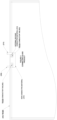
- FIGS. 5A and 5B illustrate an example of a greenhouse electricity-generating system 500 according to an embodiment of the invention.
- a portion of a greenhouse can include a module having a frame 502 (i.e., a greenhouse frame) supporting one or more homogeneous transparent panels permitting sunlight to enter or pass through the module into an interior of the greenhouse.
- a frame 502 i.e., a greenhouse frame
- homogeneous transparent panels permitting sunlight to enter or pass through the module into an interior of the greenhouse.
- One of ordinary skill in the art will recognize that other configurations of a greenhouse or a greenhouse module can be provided.
- the embodiments of the invention are not limited to any particular type of greenhouse arrangement or configuration.
- the exemplary greenhouse electricity-generating system can include a homogeneous coated transparent electricity-generating glass or plastic device (TEGD) 300 and an electrical junction box transfer device (E-JBTD) 200.
- the homogeneous coated transparent electricity-generating glass or plastic device (TEGD) 300 can permit transmission of light into the greenhouse and onto plants within the greenhouse.
- conventional transparent c-Si (Black Body) photovoltaic (PV) modules for example, as shown in FIG. 1B
- conventional transparent photovoltaic (PV) modules with lane coated lines for example as shown in FIG.
- the exemplary embodiments of the invention can permit a larger amount of light to pass through the system, as well as a homogeneous transmission of light through the system, thereby enabling transmission of sufficient amounts of even and uniform homogeneous light for proper or desired plant growth.
- the electrical junction box transfer device (E-JBTD) 200 in the example of FIGS. 5A and 5B can include a body, one or more electrical connectors on the body, and a non-conductive dielectric insulating material protecting the one or more electrical connectors. As shown in FIGS.
- the exemplary electrical junction box transfer device (E-JBTD) 200 can be located on the homogeneous transparent electricity-generating glass or plastic device (TEGD) 300 such that interference or obstruction of light transmission through the coatings into the interior of the greenhouse can be prevented or minimized, thereby resulting in a larger amount of light and transmission of light into the greenhouse and onto plants within the greenhouse to improve, even and efficient growth of such plants, while at the same time providing desired amounts of electricity generation.
- TEGD homogeneous transparent electricity-generating glass or plastic device
Landscapes
- Engineering & Computer Science (AREA)
- Architecture (AREA)
- Civil Engineering (AREA)
- Structural Engineering (AREA)
- Photovoltaic Devices (AREA)
- Life Sciences & Earth Sciences (AREA)
- Connection Or Junction Boxes (AREA)
- Chemical & Material Sciences (AREA)
- Materials Engineering (AREA)
- Soil Sciences (AREA)
- Environmental Sciences (AREA)
- Lining Or Joining Of Plastics Or The Like (AREA)
Description
- The present invention is directed to a system for collecting electrical energy produced by a homogeneous transparent electricity-generating glass or plastic devices (TEGD) in greenhouse environments, and more particularly, to a system for a greenhouse including a homogeneous transparent electricity-generating glass or plastic devices (TEGD) and an associated internal electrical module junction box transfer device (E-JBTD), and more particularly, to a greenhouse including a system having a homogeneous transparent electricity-generating glass or plastic devices (TEGD) and an associated internal electrical module junction box transfer device (E-JBTD).
- Modern commercial greenhouses (aka glasshouse or a hothouse) are becoming increasingly technologically advanced buildings that are desirably capable of operating in ever-increasing efficient manners. The modern greenhouse demands energy efficiency and reduced energy consumption to produce in-demand products. A typical greenhouse is a structure with walls and roof made chiefly of transparent material, such as glass or plastic, in which plants requiring regulated climatic conditions are grown. These greenhouse structures range in size from small sheds to industrial-sized buildings occupying acres of space.
- A typical greenhouse utilizing conventional mono- or poly-crystalline silicon, thin-film, etc. may include Solar Photovoltaic (PV) modules that are either ground-mounted or placed on rack systems mounted directly to the frame, which may shade natural light required for optimum plant or vegetable growth. The current conventional non-transparent black body electricity generating PV module, while being capable of manufacturing electricity may not be capable of permitting enough light to pass into the greenhouse to enable electricity generation and plant growth at the same time. The typical PV module is not designed to let required light for plant growth to move through the module, but instead, is designed to block almost all light, thereby allowing for electricity generation only.
-
US 2019/089294 A1 describes module connectors for flexible photovoltaic modules. -
US 2016/013433 A1 describes the application of transparent organic solar cells in a greenhouse, which includes an enclosing structure including transparent organic photo-voltaic cell being that is at least 10% transparent to sun light. - The present invention provides a system according to claim 1 and a greenhouse electricity-generating system comprising an organic photovoltaic homogeneous coated electrical generating laminated device as defined in the appended claims
- The present invention recognizes that it is desirable that greenhouses permit as much visible light as possible to pass completely through an electricity-generating device, such as an electricity-generating device that replaces typical greenhouse glass or plastic materials, so that the electricity-generating device appears as either transparent, or mostly transparent with only a moderate visible tint. The present invention further recognizes that transparent or semitransparent organic photovoltaic devices may be innocuously used in conjunction with greenhouse glass or plastic windows to avoid installation of light blocking traditional photovoltaic greenhouse frame mounted array systems.
- For the reasons stated above and for other reasons stated below which will become apparent to those skilled in the art upon reading and understanding the specification, there is a need in the art for transparent organic photovoltaic greenhouse structures and devices.
- The embodiments of the present invention provide methods and systems for transparent organic photovoltaic devices and will be understood by reading and studying the following specification.
- The present invention also recognizes that the discrete points of contacts or connections in conventional electrical wiring connection systems present challenges for the installation of homogeneous transparent electricity-generating glass or plastic devices (TEGD) that have limited or constrained access by space or location. The present invention also recognizes that current greenhouse framing systems present a challenge in safely securing transparent electricity-generating glass or plastic devices (TEGD) to typical greenhouse structures, while at the same time allowing for easy unimpaired wiring configurations.
- In the conventional art, the installation of a homogeneous transparent electricity-generating glass or plastic device (TEGD) and associated with the use of a conventional electrical J-Box device may be compromised or prohibited by difficult, if not impossible, installations due to space, fixture, building and mounting constraints that do not allow proper or secure module mounting, or electrical connection.
- As shown for example in
FIGS. 1B and 1C , the current conventional art renewable products and devices are not configured to permit, and are not capable of permitting, even, required light to pass through the module into the greenhouse in order to allow for plant growth, while at the same time providing ample amounts of electricity generation simultaneously by the same device. For example, as illustrated inFIG. 1C , conventional or transparent photovoltaic (PV) devices, bi-facial lane coated modules, and amorphous silica type PV modules have lines of uncoated glass or plastic that has visually and light distorting lines and semitransparent wide coated lines that may interfere with, obstruct, or limit light transmission through the coatings into the interior of the greenhouse, thereby resulting in blocked light transmission into the greenhouse and onto plants within the greenhouse, which may have a detrimental negative effect on the growing of such plants. - Moreover, as illustrated in
FIG. 1B , the current art of non-transparent c-Si (Black Body) photovoltaic (PV) modules will only allow a small portion of light to pass through the module, between the black body semiconductors which results in the plants receiving very limited, insufficient amounts of light for proper or desired plant growth. - In addition, in conventional PV interconnected systems and arrangements, the associated electrical J-Box is mounted to the back of a module attached to the back of drilled glass or plastic and is oriented in such a way that the system, or parts thereof, cast undesirable shadows on surfaces within the greenhouse. The conventional systems and arrangements also may suffer from improper wire management allowing for flawed aesthetics and imperfections and further affecting light transmission, shadows, etc.
- The present invention recognizes that there is a need for this art in the industry for replacing passive uncoated glass or plastic systems and conventional PV electricity-generating devices and associated J-Box electrical connections with improved homogeneous transparent electricity-generating devices (TEGD) and associated and simplified internal- and external-connection systems for collecting the electrical energy produced by the homogeneous transparent electricity-generating glass or plastic devices (TEGD), in greenhouse environments.
- To solve these and other related mounting, light transmittance and electrical connection issues, the present invention provides a system including a novel homogeneous transparent electricity-generating device and associated internal electrical module junction box transfer device (E-JBTD) that reduces costs, increases needed light, improves efficiency, safety and electrical connectivity, and improves and simplifies the installation process, thereby providing important advantages for electricity production for homogeneous transparent electricity-generating glass or plastic devices (TEGD) needed by the modern efficient greenhouse.
- The present invention further provides a novel homogeneously, uniform, applied Organic Photovoltaic (OPV) coating that is even across the whole expanse of the entire, edge-to-edge, surface of the glass or plastic, allowing for even light transmittance. The OPV coating allowing even light across the entire module comes in various colors and visual light transmittance (VLT) levels. The ability in modifying color and VLT will allow the greenhouse to be specifically designed in the most efficient way based upon the product being grown. The present invention also provides an internal electrical module junction box transfer device (E-JBTD) that allows homogeneous transparent electricity-generating glass or plastic devices (TEGD) to maintain connection tightness, structural integrity, function, and purpose of a module, laminated veneer, etc., and all other glass or plastic fabricated products and devices, to function as designed and fabricated while allowing effective electricity transfer from the electricity-generating surface(s) or coatings of the transparent electricity-generating glass or plastic devices (TEGD) to the internal and external elements of the electrical module junction box transfer device (E-JBTD). The exemplary embodiments of the invention allow for maximum light transmittance, and efficient electricity transfer using homogeneous transparent electricity-generating glass or plastic devices (TEGD), while at the same time maintaining all of the performance properties regarding light transfer, electricity and power generation, and required plant growth.
- The present invention further recognizes that the combining of an exemplary homogeneous coated transparent electricity-generating glass or plastic device (TEGD) and an electrical module junction box transfer device (E-JBTD) will allow productive, efficient, and effective electricity transfer from the device for use in a greenhouse environment. According to example embodiments of the invention, an electrical module junction box transfer device (E-JBTD) can be configured as an integral part of any electricity-generating glass or plastic (EGP) or homogeneous transparent electricity-generating glass or plastic device (TEGD) module. It is desirable, and in some cases critical, that electron transfer from the electrical coating and/or connections on the inside of the electricity-generating glass or plastic devices (TEGD) be safely, efficiently, and/or effectively interconnected to the external frame mounted wiring systems for electricity transfer.
- The homogeneous electricity-generating glass or plastic device (TEGD) and the electrical module junction box transfer device (E-JBTD) can include engagement devices at opposite electrical series or parallel string terminal connections configured to maximize voltage and current for effective power levels needed for proper connection to other balance of systems (BOS) components.
- The homogeneous electricity-generating glass or plastic device (TEGD) and the electrical module junction box transfer device (E-JBTD) can be integrated into a typical double lite laminated glass or plastic product or device. In some examples, the OPV electricity-generating coating can be evenly applied to the second surface of the first low iron lite, laminated utilizing typical lamination films, and sandwiched between the second lite of low iron glass or plastic. The electricity-generating OPV coating is novel in inception and the connecting of the coating and the electrical module junction box transfer device (E-JBTD) can include one or more rigidly mounted in place electrical connector(s), which are physically separated by a non-conductive dielectric insulating material protecting and insulating the electrical contacts. The interconnection between the module and electrical module junction box transfer device (E-JBTD) is also novel in inception, and the completion of the connection is utilized by pressing the electrical module junction box transfer device (E-JBTD) on to the existing OPV module electrical tabs and firmly seating the electrical module junction box transfer device (E-JBTD) on the bottom of the homogeneous electricity-generating glass or plastic device (TEGD). The internal electrical connections are then translated to typical or standardized MC-4 connections, similar to common conventional electrical connections shown, for example, in
FIG. 1A . The MC-4 connections are single-contact electrical connectors commonly used for connecting solar panels and the typical industry standard with regard to module-to-module, or module-to-balance of systems (BOS) terminal wire connections. - An exemplary embodiment of the invention is directed to a homogeneous electricity-generating glass or plastic device (TEGD) and associated electrical module junction box transfer device (E-JBTD) for a transparent greenhouse electrical generating module. The homogeneous electricity-generating device (TEGD) including two or more low iron glass or plastic lites, a homogeneous applied OPV coating, and lamination film, and an electrical module junction box transfer device (E-JBTD) including one or more electrical connectors, and a non-conductive dielectric insulating material protecting the one or more electrical connectors. The homogeneous electricity-generating glass or plastic device (TEGD) and an electrical module junction box transfer device (E-JBTD) can include one or more single-contact electrical connectors electrically connected to the one or more electrical connectors. The one or more single-contact electrical connectors can include MC-4 connections.
- Other features and advantages of the present invention will become apparent to those skilled in the art upon review of the following detailed description and drawings.
- These and other aspects and features embodiments of the present invention will be better understood after reading the following detailed description, together with the attached drawings, contained herein:
-
FIG. 1A illustrates an example of a conventional male and female MC-4 connector of a photovoltaic (PV) module; -
FIG. 1B illustrates an example of a conventional bi-facial photovoltaic (PV) module; -
FIG. 1C illustrates an example of a conventional transparent photovoltaic (PV) module; -
FIG. 2A illustrates a schematic side view of an electrical module junction box transfer device (E-JBTD) according to an exemplary embodiment of the invention; -
FIG. 2B illustrates a schematic top view of an electrical module junction box transfer device (E-JBTD) according to an exemplary embodiment of the invention; -
FIG. 3A illustrates a schematic left side view of an electrical module junction box transfer device (E-JBTD) connected with a homogeneous electricity-generating glass or plastic device (TEGD) according to an exemplary embodiment of the invention; -
FIG. 3B illustrates a schematic front side view of an electrical module junction box transfer device (E-JBTD) connected with a homogeneous electricity-generating glass or plastic device (TEGD) according to an exemplary embodiment of the invention; -
FIG. 4 illustrates the bottom view of a homogeneous transparent electricity-generating device (TEGD) system including the electrical module junction box transfer device (E-JBTD) according to an exemplary embodiment of the invention; -
FIG. 5A illustrates a schematic bottom view of a greenhouse electricity-generating system according to an exemplary embodiment of the invention; and -
FIG. 5B illustrates a side view of a greenhouse electricity-generating system according to the exemplary embodiment ofFIG. 5A . - The present invention now is described more fully hereinafter with reference to the accompanying drawings, in which embodiments of the invention are shown. This invention, however, may be embodied in many different forms and should not be construed as limited to the embodiments set forth herein; rather, these embodiments are provided so that this disclosure will be thorough and complete, and will fully convey the scope of the invention to those skilled in the art.
- Referring now to the drawings, exemplary embodiments of a homogeneous transparent electricity-generating device (TEGD) and electrical module junction box transfer device (E-JBTD) will now be described.
- For background and purposes of comparison,
FIG. 1A illustrates an example of a conventional MC-4 connector that is configured to fasten and connect an electricity-generating glass or plastic device (EGD) outside rated insulated conductor to a module or other device. As explained, such MC-4 connections are single-contact electrical connectors commonly used for connecting solar panels and the typical industry standard with regard to module-to-module, or module-to-balance of systems (BOS) terminal wire connections.FIG. 1B illustrates an example of a conventional c-Si (Black Body) photovoltaic (PV) module andFIG. 1C illustrates an example of a conventional transparent lane coated photovoltaic (PV) module. -
FIGS. 2A - 5B illustrate exemplary embodiments of a system for a transparent greenhouse electrical generating module (GEGM) including an electrical module junction box transfer device (E-JBTD) 200 and a homogeneous transparent electricity-generating glass or plastic device (TEGD) 300 according to exemplary embodiments of the invention. - Particularly,
FIGS. 2A - 2B illustrate a side and top view of an example of an electrical module junction box transfer device (E-JBTD) 200. As shown in the front side (FIG. 2A ) of the electrical module junction box transfer device (E-JBTD) 200, the electrical module junction box transfer device (E-JBTD) 200 can have abody 201 including internal connection clips 202 (e.g., electron transfer clips;CLIP A 202 inFIGS. 3A, 3B ) that are configured to be pressed on to the electrical tabs (e.g.,TAB A 302 inFIGS. 3A, 3B ) emerging from the front leading edge of the homogeneous transparent electricity-generating glass or plastic device (TEGD) 300. The electron transfer clips (CLIP A 202) are connected internally within thebody 201 to the outside integrated MC-4connectors material 204 that isolates the electrical contact points between the positive and negative conductor terminals to prevent arcing. For example, the non-conductive dielectric insulatingmaterial 204 can be a separate component provided to isolate the electrical contact points between the positive and negative conductor terminals to prevent arcing, or the non-conductive dielectric insulatingmaterial 204 can be integrally formed with thebody 201, or a portion thereof, to isolate the electrical contact points between the positive and negative conductor terminals to prevent arcing. In an example, a leading edge of thebody 201 of the electrical module junction box transfer device (E-JBTD) 200 can be capped with an insulatingsilicone material FIG. 2B ) of the electrical module junction box transfer device (E-JBTD) 200 illustrates an example in which the electrical conductor points of contact are completely encased in non-conductive dielectric insulatingmaterial 204. Also, the top view illustrates an example of an internal bus bar 212 or the like, that is encapsulated with a non-conductivedielectric material 204 and runs from theinternal clip 202 to the output wire connections (e.g., 208, 210). The MC-4male 208 and female 210 connections are connections typically used to secure the output of positive and negative conductor terminal connections. In industry, thefemale connector 210 is typically positive (+) and themale connector 208 is typically negative (-). This plug and socket connection is designed to prevent accidental conductor connections. -
FIGS. 3A - 3B illustrate exemplary side and front views of an electrical module junction box transfer device (E-JBTD) 200 as it fits onto a laminated homogeneous transparent electricity-generating glass or plastic device (TEGD) ormodule 300.FIGS. 3A - 3B illustrate examples of both the side and front views and how theelectrical tab 302 extending from the EGP device/module 300 connects seamlessly to theelectrical connector clip 202 of theE-JBTD 200. Also,FIGS. 3A - 3B illustrate examples including a silicone insulating,watertight seal body 201, or a portion thereof, of the E-JBTD 200 and the glass/glass or plastic/plastic laminate of the TEGD or module 300). -
FIGS. 4 illustrates a top-down view of the homogeneous transparent electricity-generating glass or plastic device (TEGD) with an electrical module junction box transfer device (E-JBTD) 200 connected.FIG. 4 illustrates an example of a fully connected electrical module junction box transfer device (E-JBTD) 200 on an TEGD ormodule 300. In the illustrated examples, the size of the homogeneous transparent electricity-generating glass or plastic device (TEGD) is based upon the typical art used today for mounting greenhouse glass or plastic. The size, however, is not limited to the size shown in this example, and other examples can be configured differently with different sizing. For example, the size of the homogeneous transparent electricity-generating glass or plastic device (TEGD) 300 can be reduced or enlarged based upon the design of the greenhouse opening.FIG. 3B illustrates an example in which the fixture connection of the (E-JBTD) 200 can be configured to be secured with one click (i.e., a single click connection) to the TEGD ormodule 300. The electrical module junction box transfer device (E-JBTD) 200 can be configured to be easily applied to the module or homogeneous electricity-generating glass or plastic device (TEGD) 300 allowing for a safe and secure connection. In an example, once a connection between the electrical module junction box transfer devices (E-JBTD) 200 is made with the homogeneous electricity-generating glass or plastic device (TEGD) 300, it is not to be removed and reinstalled on another module or transparent electricity-generating glass or plastic device (TEGD) 300. In some examples, the electrical module junction box transfer device (E-JBTD) 200 can be such that it is not reusable, and is not intended to be removed (e.g., is not capable of being removed) once installed at the factory. -
FIGS. 5A and 5B illustrate an example of a greenhouse electricity-generatingsystem 500 according to an embodiment of the invention. As shown inFIGS. 5A and 5B , a portion of a greenhouse can include a module having a frame 502 (i.e., a greenhouse frame) supporting one or more homogeneous transparent panels permitting sunlight to enter or pass through the module into an interior of the greenhouse. One of ordinary skill in the art will recognize that other configurations of a greenhouse or a greenhouse module can be provided. The embodiments of the invention are not limited to any particular type of greenhouse arrangement or configuration. - The exemplary greenhouse electricity-generating system can include a homogeneous coated transparent electricity-generating glass or plastic device (TEGD) 300 and an electrical junction box transfer device (E-JBTD) 200. The homogeneous coated transparent electricity-generating glass or plastic device (TEGD) 300 can permit transmission of light into the greenhouse and onto plants within the greenhouse. In contrast with conventional transparent c-Si (Black Body) photovoltaic (PV) modules, for example, as shown in
FIG. 1B and conventional transparent photovoltaic (PV) modules with lane coated lines, for example as shown inFIG. 1C , the exemplary embodiments of the invention can permit a larger amount of light to pass through the system, as well as a homogeneous transmission of light through the system, thereby enabling transmission of sufficient amounts of even and uniform homogeneous light for proper or desired plant growth. - Similar to the example embodiments described with reference to
FIGS. 2A - 4 , the electrical junction box transfer device (E-JBTD) 200 in the example ofFIGS. 5A and 5B can include a body, one or more electrical connectors on the body, and a non-conductive dielectric insulating material protecting the one or more electrical connectors. As shown inFIGS. 5A and 5B , the exemplary electrical junction box transfer device (E-JBTD) 200 can be located on the homogeneous transparent electricity-generating glass or plastic device (TEGD) 300 such that interference or obstruction of light transmission through the coatings into the interior of the greenhouse can be prevented or minimized, thereby resulting in a larger amount of light and transmission of light into the greenhouse and onto plants within the greenhouse to improve, even and efficient growth of such plants, while at the same time providing desired amounts of electricity generation. - The present invention has been described herein in terms of several preferred embodiments. However, modifications and additions to these embodiments will become apparent to those of ordinary skill in the art upon a reading of the foregoing description. It is intended that all such modifications and additions comprise a part of the present invention to the extent that they fall within the scope of the several claims appended hereto.
Claims (14)
- A system comprising:an organic photovoltaic homogeneous coated electrical generating laminated device (300) including a double laminated coated electrical device; andan electrical module junction box transfer device (200) integrated into an edge of the organic photovoltaic homogeneous coated electrical generating laminated device, the electrical module junction box transfer device (200) including:a body (201);one or more electrical connectors (208, 210) on the body wherein the one or more electrical connectors (208, 210) include at least one connection clip (202) internally within the body (201); andan internal bus bar (212), which runs from the connection clip (202) to the one or more output electrical connectors (208, 210), wherein the internal bus bar (212) is encapsulated with a non-conductive dielectric insulating material (204) and the non-conductive dielectric insulating material (204) encases the one or more electrical connectors (208, 210).
- The system of claim 1, wherein the organic photovoltaic homogeneous coated electrical generating laminated device (300) includes one low iron lite coated with a homogeneous organic photovoltaic coating and laminated between one or more lites utilizing a laminate film.
- The system of claim 1, wherein the organic photovoltaic homogeneous coated electrical generating laminated device (300) further comprises:
two electrical bus bars (212) contained between two lites of laminated glass or plastic egressing out of two openings in a bottom lite of glass or plastic. - The system of claim 1, wherein the organic photovoltaic (OPV) homogeneous coated electrical generating laminated device further comprises:
a glass or plastic portion having two drilled holes and capped with an insulating material (206, 207) that is configured to provide a liquid-tight connection. - The system of claim 1, wherein the one or more electrical connectors (208, 210) of the electrical module junction box transfer device (200) includes at least two electrical connectors (208, 210), and
wherein the non-conductive dielectric insulating material (204) physically separates the at least two electrical conductor connectors (208, 210). - The system of claim 1, wherein the electrical module junction box transfer device (200) further comprises:
one or more single-contact electrical conductor connectors electrically connected to the one or more electrical connectors. - The system of claim 6, wherein the one or more single-contact electrical conductor connectors includes an MC-4 connection.
- The system of claim 5, further comprising at least two single-contact electrical connectors electrically connected to the at least two electrical connectors, wherein the at least two single-contact electrical conductor connectors include MC-4 connections.
- The system of claim 8, wherein one of the MC-4 connections includes a male MC-4 connection (208) and another of the MC-4 connections includes a female MC-4 connection (210).
- The system of claim 1, wherein an edge of the body of the electrical module junction box transfer device (200) is capped with an insulating material that is configured to provide a liquid-tight connection to the organic photovoltaic homogeneous coated electrical generating laminated device.
- The system of claim 1, wherein the one or more electrical connectors (208, 210) are completely isolated from each other by the non-conductive dielectric insulating material (204).
- The system of claim 6, further comprising:
an internal bus-bar (212) electrically connecting the one or more single-contact electrical connectors to the one or more electrical connectors and encapsulated within the non-conductive dielectric insulating material (204). - A greenhouse electricity-generating system comprising:the organic photovoltaic homogeneous coated electrical generating laminated device (300) and the electrical module junction box transfer device (200) of claim 1,wherein the electrical module junction box transfer device (200) is on the organic photovoltaic homogeneous coated electrical generating laminated device (300).
- The system of claim 13, further comprising:
an insulating material between the organic photovoltaic homogeneous coated electrical generating laminated device and the electrical module junction box transfer device and configured to provide a liquid-tight connection between the organic photovoltaic homogeneous coated electrical generating laminated device and electrical module junction box transfer device.
Applications Claiming Priority (3)
| Application Number | Priority Date | Filing Date | Title |
|---|---|---|---|
| US201962854276P | 2019-05-29 | 2019-05-29 | |
| US16/660,388 US20200382052A1 (en) | 2019-05-29 | 2019-10-22 | Homogeneous transparent coated greenhouse electrical generating devices, and internal and external electrical interconnections |
| PCT/US2020/034845 WO2020243251A1 (en) | 2019-05-29 | 2020-05-28 | Homogeneous transparent coated greenhouse electrical generating devices, and internal and external electrical interconnections |
Publications (4)
| Publication Number | Publication Date |
|---|---|
| EP3959754A1 EP3959754A1 (en) | 2022-03-02 |
| EP3959754A4 EP3959754A4 (en) | 2023-01-18 |
| EP3959754C0 EP3959754C0 (en) | 2024-12-25 |
| EP3959754B1 true EP3959754B1 (en) | 2024-12-25 |
Family
ID=73549655
Family Applications (2)
| Application Number | Title | Priority Date | Filing Date |
|---|---|---|---|
| EP20814433.7A Active EP3959754B1 (en) | 2019-05-29 | 2020-05-28 | Homogeneous transparent coated greenhouse electrical generating devices, and internal and external electrical interconnections |
| EP20813869.3A Withdrawn EP3959813A4 (en) | 2019-05-29 | 2020-05-28 | ELECTRICAL MODULE JUNCTION BOX TRANSFER DEVICE SYSTEM (E-JBTD) HAVING INTERNAL AND EXTERNAL ELECTRICAL POWER CONNECTIONS |
Family Applications After (1)
| Application Number | Title | Priority Date | Filing Date |
|---|---|---|---|
| EP20813869.3A Withdrawn EP3959813A4 (en) | 2019-05-29 | 2020-05-28 | ELECTRICAL MODULE JUNCTION BOX TRANSFER DEVICE SYSTEM (E-JBTD) HAVING INTERNAL AND EXTERNAL ELECTRICAL POWER CONNECTIONS |
Country Status (6)
| Country | Link |
|---|---|
| US (1) | US20200382052A1 (en) |
| EP (2) | EP3959754B1 (en) |
| CN (2) | CN114270553B (en) |
| CA (1) | CA3140005A1 (en) |
| MX (1) | MX2021014559A (en) |
| WO (1) | WO2020243251A1 (en) |
Family Cites Families (23)
| Publication number | Priority date | Publication date | Assignee | Title |
|---|---|---|---|---|
| JP3443029B2 (en) * | 1999-03-30 | 2003-09-02 | 鐘淵化学工業株式会社 | Solar cell module, power generation device, and method of manufacturing solar cell module |
| DE10358140B4 (en) * | 2003-12-10 | 2006-01-05 | Günther Spelsberg GmbH & Co. KG | Electrical connection and connection box for a solar cell module |
| EP2058867A3 (en) * | 2007-11-12 | 2009-07-22 | Multi-Holding AG | Junction box for a photovoltaic solar panel |
| EP2232577A1 (en) * | 2007-12-18 | 2010-09-29 | Day4 Energy Inc. | Photovoltaic module with edge access to pv strings, interconnection method, apparatus, and system |
| CN102047432B (en) * | 2007-12-21 | 2013-07-17 | 纳幕尔杜邦公司 | Photovoltaic array, framework, and methods of installation and use |
| EP2253023B2 (en) * | 2008-03-11 | 2022-11-09 | (CNBM) Bengbu Design & Research Institute for Glass Industry Co., Ltd. | Solar module |
| WO2010014941A1 (en) * | 2008-07-31 | 2010-02-04 | Daystar Technologies, Inc. | Solar modules, solar module junction boxes, and methods for mounting junction boxes to solar modules |
| DE102008052348B4 (en) * | 2008-10-20 | 2016-12-29 | Te Connectivity Germany Gmbh | Connecting device for connecting an electrical conductor with a solar module, and solar module with such a connection device |
| US20100116325A1 (en) * | 2008-11-12 | 2010-05-13 | Mehrdad Nikoonahad | High efficiency solar panel and system |
| US20120048349A1 (en) * | 2009-01-09 | 2012-03-01 | Solopower, Inc. | Flexible solar modules and manufacturing the same |
| TW201034562A (en) * | 2009-03-18 | 2010-10-01 | Lite On Technology Corp | Photovoltaic greenhouse structure |
| CN102388461B (en) * | 2009-06-29 | 2014-06-25 | 京瓷株式会社 | Terminal box for solar cell modules, and solar cell module using same |
| US20110114149A1 (en) * | 2009-11-13 | 2011-05-19 | Du Pont Apollo Limited | Junction box and photovoltaic module having junction box |
| DE202009017451U1 (en) * | 2009-12-23 | 2010-03-18 | Yamaichi Electronics Deutschland Gmbh | Solar module, junction box and solar module connector assembly |
| US8962998B2 (en) * | 2012-02-08 | 2015-02-24 | Shoals Technologies Group, Llc | Solar panel junction box capable of integrating with a variety of accessory modules, and method of use |
| DE102012106241A1 (en) * | 2012-07-11 | 2014-05-22 | Phoenix Contact Gmbh & Co. Kg | Edge connector for photovoltaic solar modules |
| US9899955B2 (en) * | 2012-09-02 | 2018-02-20 | Pv Solutions, Llc | Integrated electrical and mechanical photovoltaic array interconnection system |
| US20160013433A1 (en) * | 2013-02-25 | 2016-01-14 | The Regents Of The University Of California | Transparent organic solar cells for agronomic applications |
| US9985580B2 (en) * | 2015-06-03 | 2018-05-29 | Te Connectivity Corporation | Solar junction box for solar panel |
| US20170194900A1 (en) * | 2015-12-30 | 2017-07-06 | Solarcity Corporation | Methods for mounting a junction box on a glass solar module with cutout |
| CN105634389B (en) | 2016-03-15 | 2018-09-14 | 苏州腾晖光伏技术有限公司 | photovoltaic module unit and photovoltaic ecological greenhouse |
| US20170317305A1 (en) * | 2016-04-28 | 2017-11-02 | Solarwindow Technologies, Inc. | Systems and methods for transparent organic photovoltaic devices |
| US10425035B2 (en) * | 2017-09-15 | 2019-09-24 | Miasolé Hi-Tech Corp. | Module connector for flexible photovoltaic module |
-
2019
- 2019-10-22 US US16/660,388 patent/US20200382052A1/en not_active Abandoned
-
2020
- 2020-05-28 CN CN202080039670.8A patent/CN114270553B/en active Active
- 2020-05-28 CA CA3140005A patent/CA3140005A1/en active Pending
- 2020-05-28 CN CN202080039587.0A patent/CN114287106A/en active Pending
- 2020-05-28 WO PCT/US2020/034845 patent/WO2020243251A1/en not_active Ceased
- 2020-05-28 MX MX2021014559A patent/MX2021014559A/en unknown
- 2020-05-28 EP EP20814433.7A patent/EP3959754B1/en active Active
- 2020-05-28 EP EP20813869.3A patent/EP3959813A4/en not_active Withdrawn
Also Published As
| Publication number | Publication date |
|---|---|
| WO2020243251A1 (en) | 2020-12-03 |
| CN114270553B (en) | 2025-08-01 |
| CN114270553A (en) | 2022-04-01 |
| US20200382052A1 (en) | 2020-12-03 |
| EP3959754C0 (en) | 2024-12-25 |
| EP3959813A4 (en) | 2023-04-26 |
| EP3959754A4 (en) | 2023-01-18 |
| CA3140005A1 (en) | 2020-12-03 |
| EP3959813A1 (en) | 2022-03-02 |
| EP3959754A1 (en) | 2022-03-02 |
| CN114287106A (en) | 2022-04-05 |
| MX2021014559A (en) | 2022-05-19 |
Similar Documents
| Publication | Publication Date | Title |
|---|---|---|
| US9331213B2 (en) | Integrated power connectors for PV modules and their methods of manufacture | |
| EP2652794B1 (en) | Diode-included connector and photovoltaic assembly using same | |
| KR101305863B1 (en) | Photovoltaic modules | |
| US20100275976A1 (en) | Photovoltaic module with edge access to pv strings, interconnection method, apparatus, and system | |
| EP3314747B1 (en) | Solar junction box | |
| EP3304602B1 (en) | Solar junction box for solar panel | |
| US10256769B2 (en) | Terminal for solar junction box | |
| US20140352754A1 (en) | Connector and solar cell module comprising the same | |
| US20140182651A1 (en) | Integrated junction insulation for photovoltaic module | |
| US9184326B2 (en) | Solar cell module | |
| US20200382052A1 (en) | Homogeneous transparent coated greenhouse electrical generating devices, and internal and external electrical interconnections | |
| EP3314749A1 (en) | Cable termination for solar junction box | |
| US20190074794A1 (en) | Photovoltaic module, trunk cable, and photovoltaic module including the same | |
| HK40072210A (en) | Homogeneous transparent coated greenhouse electrical generating devices, and internal and external electrical interconnections | |
| US9685574B2 (en) | Solar cell module | |
| CN223109970U (en) | Thin-film solar cells and solar cell modules | |
| US20150075586A1 (en) | Solar cell module | |
| US20210044096A1 (en) | Electrical module junction box transfer device (e-jbtd) system having electrical energy internal and external connections | |
| HK40072757A (en) | Electrical module junction box transfer device (e-jbtd) system having electrical energy internal and external connections |
Legal Events
| Date | Code | Title | Description |
|---|---|---|---|
| STAA | Information on the status of an ep patent application or granted ep patent |
Free format text: STATUS: THE INTERNATIONAL PUBLICATION HAS BEEN MADE |
|
| PUAI | Public reference made under article 153(3) epc to a published international application that has entered the european phase |
Free format text: ORIGINAL CODE: 0009012 |
|
| STAA | Information on the status of an ep patent application or granted ep patent |
Free format text: STATUS: REQUEST FOR EXAMINATION WAS MADE |
|
| 17P | Request for examination filed |
Effective date: 20211124 |
|
| AK | Designated contracting states |
Kind code of ref document: A1 Designated state(s): AL AT BE BG CH CY CZ DE DK EE ES FI FR GB GR HR HU IE IS IT LI LT LU LV MC MK MT NL NO PL PT RO RS SE SI SK SM TR |
|
| DAV | Request for validation of the european patent (deleted) | ||
| DAX | Request for extension of the european patent (deleted) | ||
| A4 | Supplementary search report drawn up and despatched |
Effective date: 20221220 |
|
| RIC1 | Information provided on ipc code assigned before grant |
Ipc: H02S 40/34 20140101ALI20221214BHEP Ipc: H01L 51/42 20060101AFI20221214BHEP |
|
| REG | Reference to a national code |
Ref country code: DE Ref country code: DE Ref legal event code: R079 Ref document number: 602020043770 Country of ref document: DE Free format text: PREVIOUS MAIN CLASS: H01L0051000000 Ipc: H02S0040340000 |
|
| GRAP | Despatch of communication of intention to grant a patent |
Free format text: ORIGINAL CODE: EPIDOSNIGR1 |
|
| STAA | Information on the status of an ep patent application or granted ep patent |
Free format text: STATUS: GRANT OF PATENT IS INTENDED |
|
| RIC1 | Information provided on ipc code assigned before grant |
Ipc: H02S 20/23 20140101ALI20240618BHEP Ipc: H02S 40/36 20140101ALI20240618BHEP Ipc: H02S 40/34 20140101AFI20240618BHEP |
|
| INTG | Intention to grant announced |
Effective date: 20240719 |
|
| GRAS | Grant fee paid |
Free format text: ORIGINAL CODE: EPIDOSNIGR3 |
|
| GRAA | (expected) grant |
Free format text: ORIGINAL CODE: 0009210 |
|
| STAA | Information on the status of an ep patent application or granted ep patent |
Free format text: STATUS: THE PATENT HAS BEEN GRANTED |
|
| AK | Designated contracting states |
Kind code of ref document: B1 Designated state(s): AL AT BE BG CH CY CZ DE DK EE ES FI FR GB GR HR HU IE IS IT LI LT LU LV MC MK MT NL NO PL PT RO RS SE SI SK SM TR |
|
| REG | Reference to a national code |
Ref country code: GB Ref legal event code: FG4D |
|
| REG | Reference to a national code |
Ref country code: CH Ref legal event code: EP |
|
| REG | Reference to a national code |
Ref country code: DE Ref legal event code: R096 Ref document number: 602020043770 Country of ref document: DE |
|
| REG | Reference to a national code |
Ref country code: IE Ref legal event code: FG4D |
|
| U01 | Request for unitary effect filed |
Effective date: 20241225 |
|
| U07 | Unitary effect registered |
Designated state(s): AT BE BG DE DK EE FI FR IT LT LU LV MT NL PT RO SE SI Effective date: 20250110 |
|
| PG25 | Lapsed in a contracting state [announced via postgrant information from national office to epo] |
Ref country code: HR Free format text: LAPSE BECAUSE OF FAILURE TO SUBMIT A TRANSLATION OF THE DESCRIPTION OR TO PAY THE FEE WITHIN THE PRESCRIBED TIME-LIMIT Effective date: 20241225 |
|
| PG25 | Lapsed in a contracting state [announced via postgrant information from national office to epo] |
Ref country code: NO Free format text: LAPSE BECAUSE OF FAILURE TO SUBMIT A TRANSLATION OF THE DESCRIPTION OR TO PAY THE FEE WITHIN THE PRESCRIBED TIME-LIMIT Effective date: 20250325 |
|
| PG25 | Lapsed in a contracting state [announced via postgrant information from national office to epo] |
Ref country code: GR Free format text: LAPSE BECAUSE OF FAILURE TO SUBMIT A TRANSLATION OF THE DESCRIPTION OR TO PAY THE FEE WITHIN THE PRESCRIBED TIME-LIMIT Effective date: 20250326 |
|
| PG25 | Lapsed in a contracting state [announced via postgrant information from national office to epo] |
Ref country code: RS Free format text: LAPSE BECAUSE OF FAILURE TO SUBMIT A TRANSLATION OF THE DESCRIPTION OR TO PAY THE FEE WITHIN THE PRESCRIBED TIME-LIMIT Effective date: 20250325 |
|
| U20 | Renewal fee for the european patent with unitary effect paid |
Year of fee payment: 6 Effective date: 20250416 |
|
| PG25 | Lapsed in a contracting state [announced via postgrant information from national office to epo] |
Ref country code: SM Free format text: LAPSE BECAUSE OF FAILURE TO SUBMIT A TRANSLATION OF THE DESCRIPTION OR TO PAY THE FEE WITHIN THE PRESCRIBED TIME-LIMIT Effective date: 20241225 |
|
| PG25 | Lapsed in a contracting state [announced via postgrant information from national office to epo] |
Ref country code: PL Free format text: LAPSE BECAUSE OF FAILURE TO SUBMIT A TRANSLATION OF THE DESCRIPTION OR TO PAY THE FEE WITHIN THE PRESCRIBED TIME-LIMIT Effective date: 20241225 |
|
| PG25 | Lapsed in a contracting state [announced via postgrant information from national office to epo] |
Ref country code: ES Free format text: LAPSE BECAUSE OF FAILURE TO SUBMIT A TRANSLATION OF THE DESCRIPTION OR TO PAY THE FEE WITHIN THE PRESCRIBED TIME-LIMIT Effective date: 20241225 |
|
| PGFP | Annual fee paid to national office [announced via postgrant information from national office to epo] |
Ref country code: GB Payment date: 20250411 Year of fee payment: 6 |
|
| PG25 | Lapsed in a contracting state [announced via postgrant information from national office to epo] |
Ref country code: IS Free format text: LAPSE BECAUSE OF FAILURE TO SUBMIT A TRANSLATION OF THE DESCRIPTION OR TO PAY THE FEE WITHIN THE PRESCRIBED TIME-LIMIT Effective date: 20250425 |
|
| PG25 | Lapsed in a contracting state [announced via postgrant information from national office to epo] |
Ref country code: SK Free format text: LAPSE BECAUSE OF FAILURE TO SUBMIT A TRANSLATION OF THE DESCRIPTION OR TO PAY THE FEE WITHIN THE PRESCRIBED TIME-LIMIT Effective date: 20241225 |
|
| PG25 | Lapsed in a contracting state [announced via postgrant information from national office to epo] |
Ref country code: CZ Free format text: LAPSE BECAUSE OF FAILURE TO SUBMIT A TRANSLATION OF THE DESCRIPTION OR TO PAY THE FEE WITHIN THE PRESCRIBED TIME-LIMIT Effective date: 20241225 |
|
| PLBE | No opposition filed within time limit |
Free format text: ORIGINAL CODE: 0009261 |
|
| STAA | Information on the status of an ep patent application or granted ep patent |
Free format text: STATUS: NO OPPOSITION FILED WITHIN TIME LIMIT |
|
| REG | Reference to a national code |
Ref country code: CH Ref legal event code: L10 Free format text: ST27 STATUS EVENT CODE: U-0-0-L10-L00 (AS PROVIDED BY THE NATIONAL OFFICE) Effective date: 20251105 |
|
| 26N | No opposition filed |
Effective date: 20250926 |
|
| REG | Reference to a national code |
Ref country code: CH Ref legal event code: H13 Free format text: ST27 STATUS EVENT CODE: U-0-0-H10-H13 (AS PROVIDED BY THE NATIONAL OFFICE) Effective date: 20251223 |
|
| PG25 | Lapsed in a contracting state [announced via postgrant information from national office to epo] |
Ref country code: CH Free format text: LAPSE BECAUSE OF NON-PAYMENT OF DUE FEES Effective date: 20250531 |
|
| PG25 | Lapsed in a contracting state [announced via postgrant information from national office to epo] |
Ref country code: MC Free format text: LAPSE BECAUSE OF FAILURE TO SUBMIT A TRANSLATION OF THE DESCRIPTION OR TO PAY THE FEE WITHIN THE PRESCRIBED TIME-LIMIT Effective date: 20241225 |
|
| PG25 | Lapsed in a contracting state [announced via postgrant information from national office to epo] |
Ref country code: IE Free format text: LAPSE BECAUSE OF NON-PAYMENT OF DUE FEES Effective date: 20250528 |