EP3959359B1 - Electrochemical system for the selective reduction of carbon monoxide into methanol - Google Patents
Electrochemical system for the selective reduction of carbon monoxide into methanol Download PDFInfo
- Publication number
- EP3959359B1 EP3959359B1 EP20719666.8A EP20719666A EP3959359B1 EP 3959359 B1 EP3959359 B1 EP 3959359B1 EP 20719666 A EP20719666 A EP 20719666A EP 3959359 B1 EP3959359 B1 EP 3959359B1
- Authority
- EP
- European Patent Office
- Prior art keywords
- cathodic
- anodic
- electrolyte solution
- solvent
- electrochemical system
- Prior art date
- Legal status (The legal status is an assumption and is not a legal conclusion. Google has not performed a legal analysis and makes no representation as to the accuracy of the status listed.)
- Active
Links
Images


Classifications
-
- C—CHEMISTRY; METALLURGY
- C25—ELECTROLYTIC OR ELECTROPHORETIC PROCESSES; APPARATUS THEREFOR
- C25B—ELECTROLYTIC OR ELECTROPHORETIC PROCESSES FOR THE PRODUCTION OF COMPOUNDS OR NON-METALS; APPARATUS THEREFOR
- C25B1/00—Electrolytic production of inorganic compounds or non-metals
- C25B1/01—Products
-
- C—CHEMISTRY; METALLURGY
- C25—ELECTROLYTIC OR ELECTROPHORETIC PROCESSES; APPARATUS THEREFOR
- C25B—ELECTROLYTIC OR ELECTROPHORETIC PROCESSES FOR THE PRODUCTION OF COMPOUNDS OR NON-METALS; APPARATUS THEREFOR
- C25B1/00—Electrolytic production of inorganic compounds or non-metals
- C25B1/01—Products
- C25B1/02—Hydrogen or oxygen
- C25B1/04—Hydrogen or oxygen by electrolysis of water
-
- C—CHEMISTRY; METALLURGY
- C25—ELECTROLYTIC OR ELECTROPHORETIC PROCESSES; APPARATUS THEREFOR
- C25B—ELECTROLYTIC OR ELECTROPHORETIC PROCESSES FOR THE PRODUCTION OF COMPOUNDS OR NON-METALS; APPARATUS THEREFOR
- C25B1/00—Electrolytic production of inorganic compounds or non-metals
- C25B1/01—Products
- C25B1/23—Carbon monoxide or syngas
-
- C—CHEMISTRY; METALLURGY
- C25—ELECTROLYTIC OR ELECTROPHORETIC PROCESSES; APPARATUS THEREFOR
- C25B—ELECTROLYTIC OR ELECTROPHORETIC PROCESSES FOR THE PRODUCTION OF COMPOUNDS OR NON-METALS; APPARATUS THEREFOR
- C25B11/00—Electrodes; Manufacture thereof not otherwise provided for
- C25B11/02—Electrodes; Manufacture thereof not otherwise provided for characterised by shape or form
- C25B11/03—Electrodes; Manufacture thereof not otherwise provided for characterised by shape or form perforated or foraminous
- C25B11/031—Porous electrodes
- C25B11/032—Gas diffusion electrodes
-
- C—CHEMISTRY; METALLURGY
- C25—ELECTROLYTIC OR ELECTROPHORETIC PROCESSES; APPARATUS THEREFOR
- C25B—ELECTROLYTIC OR ELECTROPHORETIC PROCESSES FOR THE PRODUCTION OF COMPOUNDS OR NON-METALS; APPARATUS THEREFOR
- C25B11/00—Electrodes; Manufacture thereof not otherwise provided for
- C25B11/04—Electrodes; Manufacture thereof not otherwise provided for characterised by the material
- C25B11/051—Electrodes formed of electrocatalysts on a substrate or carrier
- C25B11/073—Electrodes formed of electrocatalysts on a substrate or carrier characterised by the electrocatalyst material
- C25B11/075—Electrodes formed of electrocatalysts on a substrate or carrier characterised by the electrocatalyst material consisting of a single catalytic element or catalytic compound
- C25B11/085—Organic compound
-
- C—CHEMISTRY; METALLURGY
- C25—ELECTROLYTIC OR ELECTROPHORETIC PROCESSES; APPARATUS THEREFOR
- C25B—ELECTROLYTIC OR ELECTROPHORETIC PROCESSES FOR THE PRODUCTION OF COMPOUNDS OR NON-METALS; APPARATUS THEREFOR
- C25B15/00—Operating or servicing cells
- C25B15/02—Process control or regulation
- C25B15/023—Measuring, analysing or testing during electrolytic production
- C25B15/025—Measuring, analysing or testing during electrolytic production of electrolyte parameters
-
- C—CHEMISTRY; METALLURGY
- C25—ELECTROLYTIC OR ELECTROPHORETIC PROCESSES; APPARATUS THEREFOR
- C25B—ELECTROLYTIC OR ELECTROPHORETIC PROCESSES FOR THE PRODUCTION OF COMPOUNDS OR NON-METALS; APPARATUS THEREFOR
- C25B3/00—Electrolytic production of organic compounds
- C25B3/01—Products
- C25B3/07—Oxygen containing compounds
-
- C—CHEMISTRY; METALLURGY
- C25—ELECTROLYTIC OR ELECTROPHORETIC PROCESSES; APPARATUS THEREFOR
- C25B—ELECTROLYTIC OR ELECTROPHORETIC PROCESSES FOR THE PRODUCTION OF COMPOUNDS OR NON-METALS; APPARATUS THEREFOR
- C25B3/00—Electrolytic production of organic compounds
- C25B3/20—Processes
-
- C—CHEMISTRY; METALLURGY
- C25—ELECTROLYTIC OR ELECTROPHORETIC PROCESSES; APPARATUS THEREFOR
- C25B—ELECTROLYTIC OR ELECTROPHORETIC PROCESSES FOR THE PRODUCTION OF COMPOUNDS OR NON-METALS; APPARATUS THEREFOR
- C25B3/00—Electrolytic production of organic compounds
- C25B3/20—Processes
- C25B3/25—Reduction
-
- C—CHEMISTRY; METALLURGY
- C25—ELECTROLYTIC OR ELECTROPHORETIC PROCESSES; APPARATUS THEREFOR
- C25B—ELECTROLYTIC OR ELECTROPHORETIC PROCESSES FOR THE PRODUCTION OF COMPOUNDS OR NON-METALS; APPARATUS THEREFOR
- C25B3/00—Electrolytic production of organic compounds
- C25B3/20—Processes
- C25B3/25—Reduction
- C25B3/26—Reduction of carbon dioxide
-
- C—CHEMISTRY; METALLURGY
- C25—ELECTROLYTIC OR ELECTROPHORETIC PROCESSES; APPARATUS THEREFOR
- C25B—ELECTROLYTIC OR ELECTROPHORETIC PROCESSES FOR THE PRODUCTION OF COMPOUNDS OR NON-METALS; APPARATUS THEREFOR
- C25B9/00—Cells or assemblies of cells; Constructional parts of cells; Assemblies of constructional parts, e.g. electrode-diaphragm assemblies; Process-related cell features
- C25B9/05—Pressure cells
-
- B—PERFORMING OPERATIONS; TRANSPORTING
- B01—PHYSICAL OR CHEMICAL PROCESSES OR APPARATUS IN GENERAL
- B01J—CHEMICAL OR PHYSICAL PROCESSES, e.g. CATALYSIS OR COLLOID CHEMISTRY; THEIR RELEVANT APPARATUS
- B01J2231/00—Catalytic reactions performed with catalysts classified in B01J31/00
- B01J2231/60—Reduction reactions, e.g. hydrogenation
- B01J2231/62—Reductions in general of inorganic substrates, e.g. formal hydrogenation, e.g. of N2
-
- B—PERFORMING OPERATIONS; TRANSPORTING
- B01—PHYSICAL OR CHEMICAL PROCESSES OR APPARATUS IN GENERAL
- B01J—CHEMICAL OR PHYSICAL PROCESSES, e.g. CATALYSIS OR COLLOID CHEMISTRY; THEIR RELEVANT APPARATUS
- B01J2531/00—Additional information regarding catalytic systems classified in B01J31/00
- B01J2531/02—Compositional aspects of complexes used, e.g. polynuclearity
- B01J2531/0238—Complexes comprising multidentate ligands, i.e. more than 2 ionic or coordinative bonds from the central metal to the ligand, the latter having at least two donor atoms, e.g. N, O, S, P
- B01J2531/0241—Rigid ligands, e.g. extended sp2-carbon frameworks or geminal di- or trisubstitution
- B01J2531/025—Ligands with a porphyrin ring system or analogues thereof, e.g. phthalocyanines, corroles
-
- B—PERFORMING OPERATIONS; TRANSPORTING
- B01—PHYSICAL OR CHEMICAL PROCESSES OR APPARATUS IN GENERAL
- B01J—CHEMICAL OR PHYSICAL PROCESSES, e.g. CATALYSIS OR COLLOID CHEMISTRY; THEIR RELEVANT APPARATUS
- B01J2531/00—Additional information regarding catalytic systems classified in B01J31/00
- B01J2531/80—Complexes comprising metals of Group VIII as the central metal
- B01J2531/84—Metals of the iron group
- B01J2531/845—Cobalt
-
- C—CHEMISTRY; METALLURGY
- C25—ELECTROLYTIC OR ELECTROPHORETIC PROCESSES; APPARATUS THEREFOR
- C25B—ELECTROLYTIC OR ELECTROPHORETIC PROCESSES FOR THE PRODUCTION OF COMPOUNDS OR NON-METALS; APPARATUS THEREFOR
- C25B15/00—Operating or servicing cells
- C25B15/08—Supplying or removing reactants or electrolytes; Regeneration of electrolytes
Definitions
- the invention concerns a system that electrochemically reduces carbon monoxide (CO) into liquid methanol and gaseous H 2 , with a molecular catalyst.
- CO carbon monoxide
- the invention presents an electrochemical system to electrochemically reduce carbon monoxide, preferably dissolved in water, into methanol at an electrode coated with a specific ink.
- Applied potential and pH of the electrolyte are of high importance to get better Faradaic Efficiency (FE) and are described in this invention.
- the electrochemical system to electrochemically reduce CO into liquid methanol and gaseous H 2 comprises an electrochemical cell with:
- Electrochemical system to electrochemically reduce CO into liquid methanol and gaseous H 2 .
- An object of present invention is the electrochemical system to electrochemically reduce CO into liquid methanol and gaseous H 2 , comprises an electrochemical cell with:
- an electrochemical system 1 to electrochemically reduce CO into liquid methanol and gaseous H 2 comprising an electrochemical cell with:
- the cathode 4 comprises on the current collector 4A an electrode film deposit which contains: the molecular catalyst 4B, at least a binder, and optionally conductive materials as additives.
- the molecular catalyst 4B in the electrode film deposit can be in a concentration of between 1 nmol.cm -2 and 100 ⁇ mol.cm -2 .
- the cathodic current collector 4A is carbon paper
- the binder is Nafion resin
- the conductive material (additives) are made of carbon nanotubes, or carbon powder, or reduced graphene oxide or graphite powder.
- the molecular catalyst 4B comprises at least 1 and at most 8 groups among R 1 to R 16 being independently + N(C 1 -C 4 alkyl) 3 , and the other groups among R 1 to R 16 are H.
- the molecular catalyst 4B can be a cobalt phthalocyanine CoPc2 of formula (II): or a cobalt phthalocyanine CoPc3 of formula (III):
- the molecular catalyst 4B comprises at least 1 to 16 groups among R 1 to R 16 being independently F, and the other groups among R 1 to R 16 are H.
- the molecular catalyst 4B comprises at least 1 and at most 8 groups among R 1 , R 4 , R 5 , R 8 , R 9 , R 12 , R 13 and R 16 being independently a phenyl group bearing + N(C 1 -C 4 alkyl) 3 group in ortho position, and the other groups among R 1 to R 16 are H.
- R 1 to R 16 are H and the molecular catalyst 4B is a cobalt phthalocyanine CoPc of formula (I):
- the solvent 3 of the anodic electrolyte solution and of the cathodic electrolyte solution has a pH between 10.5 and 13.5.
- the solvent 3 has a pH between 12 and 13.
- the cathodic supporting electrolyte can comprise a phosphate buffer or potassium hydroxide, and the anodic supporting electrolyte can comprise a phosphate buffer or potassium hydroxide.
- the potential applied to the cathode 4 is between -0.50 V and -0.70 V versus RHE.
- the electrochemical reduction of the reagent into methanol and H 2 is carried out at room temperature.
- the electrochemical reduction of the CO reagent into methanol and H 2 can be carried out at 1 bar of CO.
- the electrochemical reduction of the CO reagent into methanol and H 2 can be carried out at several bars of CO.
- the electrochemical cell 1 can be advantageously a flow cell to electrochemically reduce a gas reactant comprising CO, passing through a gas diffusion electrode 19, into methanol.
- This flow cell presents an anodic compartment comprising:
- This flow cell presents also a cathodic compartment comprising:
- This flow cell presents also :
- the molecular catalyst 19a is defined in previous pages (molecular catalyst 4B).
- the solvent of the anodic electrolyte solution and of the cathodic electrolyte solution has a pH between 10.5 and 13.5.
- the solvent 3 has a pH between 12 and 13.
- the flow cell allows to have a higher selectivity and higher current densities.
- Electrochemical device to electrochemically reduce CO 2 into methanol and gaseous H 2 . (not according to the present invention)
- the present disclosure concerns also an electrochemical device to electrochemically reduce CO 2 into methanol and gaseous H 2 , comprising:
- the first electrochemical system 1' to electrochemically reduce CO 2 into CO can comprises an electrochemical cell with:
- the first electrochemical system 1' to electrochemically reduce CO 2 into CO presents the same molecular catalyst 4B' than the molecular catalyst 4B of the second electrochemical system 1 to electrochemically reduce CO into methanol and gaseous H 2 , as previously described.
- the solvent of the anodic electrolyte solution 3' and of the cathodic electrolyte solution has a pH between 10.5 and 13.5.
- the solvent 3' has a pH between 12 and 13.
- the first electrochemical system 1' to electrochemically reduce CO 2 into CO can present a complex of a porphyrin of formula below: wherein R 1 to R 10 and R 1' to R 10' are independently selected from the group consisting of H, F and + N(C1-C4 alkyl) 3 , and wherein:
- all the systems known from the state of the art can be used to to electrochemically reduce CO 2 into CO, such as: gold Nanoneedles or silver nanoparticules for materials, iron porphyrins or cobalt quaterpyridine or cobalt phthalocyanine as concerns molecular catalysts.
- the electrochemical system (1') to electrochemically reduce CO 2 into CO comprises an electrochemical cell with:
- cobalt phthalocyanine (CoPc, Figure 1 ) and its substituted forms as a molecular catalyst 4B for the electrochemical reduction of CO into MeOH in aqueous solutions.
- the sequential process starting from CO leads successively to HCHO and then CHsOH.
- conductive material that could be multi-wall carbon nanotubes (MWCNT) and a binder that could be Nafion resin in organic solvent 3 that could be a mixture of ethanol (EtOH) and ethylene glycol
- EtOH ethanol
- ethylene glycol ethylene glycol
- Electrolysis can then be conducted in aqueous solutions under a series of various pH conditions and CO atmosphere, or even inert gases if HCHO is used as the substrate (see Table 1 for a full description). Presence of methanol and hydrogen can then be analysed by 1 H NMR and gas chromatography (GC) respectively following electrolysis.
- GC gas chromatography
- the present patent reveals two major information:
- Cannizzaro reaction is taking place during electrolysis, accounting from some formate and a proportion of the analysed methanol.
- CoPc efficiently catalyzes the electrochemical CO 2 -to-CO conversion with high FE (92%) in aqueous solution at pH 7.2 with high current densities up to 14 mA.cm -2 .
- CO can then be used as a reactant and reduced to MeOH in aqueous solution at basic pH with up to 14.3 % efficiency (740 mV overpotential). From the total number of electrons used, the global Faradaic efficiency thus amounts to 19.5% and the chemical selectivity is equal to ca. 7.5% (see Figure 9 for details).
- Catalyst concentration was typically 15.7 ⁇ 0.7 nmol.cm -2 after dropcasting.
- the above procedure was also followed without adding any catalyst. Then, the electrode was dipped into a 50 mM solution of CoCl 2 (CoCl 2 ⁇ (H 2 O) 6 , Sigma Aldrich) under argon and a negative potential was applied (-0.624 V vs. SCE) until the desired charge was passed (2 x 16.33 nmol.cm -2 ).
- CoCl 2 CoCl 2 ⁇ (H 2 O) 6
- Sigma Aldrich argon
- a negative potential was applied (-0.624 V vs. SCE) until the desired charge was passed (2 x 16.33 nmol.cm -2 ).
- the amount of Co deposited on the film was controlled by dissolving the film (electrode surface 0.825 cm 2 ) in a 3% HNOs solution followed by filtration and ICP analysis of the solution. It led to 329 ppb of mass cobalt (calc. 318 ppb).
- Controlled potential electrolysis and cyclic voltrammetry (CVs) were performed using a PARSTAT 4000 or a PARSTAT 2273 potentiostat (Princeton Applied Research).
- the catalytic film on carbon paper is connected with a clip protected by PTFE tape (Roth).
- the reference electrodes was a Saturated Calomel Electrode (Hach) positioned as close as possible from the working electrode.
- Counter electrode was a Platinum grid (Goodfellow) immersed in the same electrolyte but separated by a glass frit bridge (Hach).
- Electrolyte was prepared on the day of the experiment by diluting potassium phosphate monobasic (analytical reagent, Prolabo), potassium phosphate dibasic (analytical reagent, Prolabo), potassium phosphate tribasic (analytical reagent, Prolabo), potassium hydroxide (Normapur, Prolabo) were used as received at the concentration mentioned in the main text.
- potassium phosphate monobasic analytical reagent, Prolabo
- potassium phosphate dibasic analytical reagent, Prolabo
- potassium phosphate tribasic analytical reagent, Prolabo
- potassium hydroxide Normal, Prolabo
- formaldehyde as the substrate were further conducted with a starting concentration of 20 mM formaldehyde.
- Electrolysis with CO as the substrate were performed under 1 atmosphere of the concerned gas, resulting in a respective concentration of 1 mM at 20°C. Electrolysis with HCOO - , HCHO or MeOH as the substrate were performed under 1 atmosphere of Argon.
- Injection was performed via a 250 ⁇ L gas-tight (Hamilton) syringe previously degassed with the gas of the experiment (CO 2 , CO or Argon). These conditions allowed for simultaneous detection of both H 2 , O 2 , N 2 , CO, CO 2 and CH 4 . Calibration curves for H 2 and CO were determined separately by injecting known quantities of pure gas.
- Liquid phase analysis was made with a Bruker AC 400 MHz NMR. Tubes were filled with 480 ⁇ L solution (392 ⁇ L of the solution of interest to which was added 40 ⁇ L of 4mM DMSO (Sigma Aldrich, Anhydrous 99.8%) and 48 ⁇ L of D 2 O (Sigma Aldrich, 99% atoms D) as internal standard). A minimum of 128 scans were accumulated with water pre-saturation method and using a relaxation time of 25 s. Quantification was made relative to the DMSO peak.
- TON product n product / n catalyst
- E CO 2 / CH 3 OH 0 ⁇ E H + / H 2 0 ⁇ 1 / nF ⁇ ⁇ f G CH 3 OH , aq 0 + ⁇ f G H 2 O , l 0 ⁇ ⁇ f G CO 2 , g 0 ⁇ ⁇ f G H 2 , g 0
- SEM Scanning electron microscopy
- XPS X-Ray Photoelectron Spectrometer analyses
- Xray absorption spectra were collected at the LUCIA beamline of SOLEIL with a ring energy of 2.75 GeV and a current of 490 mA. The energy was monochromatized by means of a Si 311 double crystal monochromator. Data were collected in a primary vacuum chamber as fluorescence spectra with an outgoing angle of 10° using a Bruker silicon drift detector. The data were normalized to the intensity of the incoming incident energy and processed with the Athena software from the IFEFFIT package. An E0 value of 7709.0 eV was used for the cobalt K-edge energy which was measured at the first inflection point. Table 1.
- Electrolysis results and Faradaic efficiencies for methanol production using CoPc as catalyst except for entries 10 (deposited metallic cobalt) and 11 (cobalt quaterpyridine).
- CO 2 and CO were used as reactant substrates upon saturation in water at 25°C and 1 atm (leading to concentration of 34 and 1 mM respectively at neutral pH).
- Concentration of HCOO - and HCHO were 10 and 20 mM respectively.
Landscapes
- Chemical & Material Sciences (AREA)
- Organic Chemistry (AREA)
- Engineering & Computer Science (AREA)
- Chemical Kinetics & Catalysis (AREA)
- Electrochemistry (AREA)
- Materials Engineering (AREA)
- Metallurgy (AREA)
- Inorganic Chemistry (AREA)
- Analytical Chemistry (AREA)
- Automation & Control Theory (AREA)
- Electrolytic Production Of Non-Metals, Compounds, Apparatuses Therefor (AREA)
Description
- The invention concerns a system that electrochemically reduces carbon monoxide (CO) into liquid methanol and gaseous H2, with a molecular catalyst.
- In the perspective of switching from fossil fuels to renewable fuels, electrochemical reduction of carbon dioxide (CO2) into methanol (MeOH) is considered as a major target. To catalyze the 6 electron, 6 proton reduction of CO2 to MeOH, efforts have been devoted to the use of metal oxides, metal alloys or chalcogenide based catalytic electrodes 1-4. Most of these materials suffer from a lack of selectivity with the generation of more reduced products (e.g. methane or C2 molecules) or require the use of rare metals 5,6. Additional stability issues arise when working outside the thermodynamic stability window of the oxides 7 leading back to the low activity observed with metal electrodes for MeOH production 8. One promising strategy to achieve high selectivity is to use molecular catalysts so as to precisely control the structure of the active site. Even though such strategy has been successfully implemented for CO2 to carbon monoxide (CO) production 9,10, no molecular catalyst has been yet shown to perform the reaction up to MeOH. Only a series of reports have been published in the 80s' with transition metal complexes but which needed assistance from heterogeneous co-catalyst (Everitt's salt) deposited on a platinum electrode to show some methanol evolution 11-13. Because the reduction of CO2 into CO can be considered as almost mature, 14-16, the present patent focuses on the subsequent and challenging reduction of CO into methanol.
- Here, the invention presents an electrochemical system to electrochemically reduce carbon monoxide, preferably dissolved in water, into methanol at an electrode coated with a specific ink. Applied potential and pH of the electrolyte are of high importance to get better Faradaic Efficiency (FE) and are described in this invention.
- The electrochemical system to electrochemically reduce CO into liquid methanol and gaseous H2, comprises an electrochemical cell with:
- an anodic compartment with:
- an anode with a current collector, and on the current collector, at least a catalyst to electrochemically oxidize H2O to O2,
- an anodic electrolyte solution comprising a solvent, and an anodic supporting electrolyte, the solvent being water, at a basic pH of between 10.5 and 13.5
- a cathodic compartment with:
- a cathodic electrolyte solution comprising the solvent, and a cathodic supporting electrolyte, the solvent being water, at a basic pH of between 10.5 and 13.5,
- the reagent CO;
- a cathode which comprises, on a current collector which is electrochemically inert, at least a molecular catalyst to electrochemically reduce CO into liquid methanol and gaseous H2, the molecular catalyst being selected :
- from the compounds of having the formula:

- R1 to R16 are independently selected from the groups consisting of H, F, +N(C1-C4 alkyl)3 group, or
- one or several of the specific following R1, R4, R5, R8, R9, R12, R13 and R16 groups being a phenyl group bearing +N(C1-C4 alkyl)3substituent in ortho position, the others groups R1 to R16 being H;
- Or the compound of formula:

- from the compounds of having the formula:
- a power supply providing the energy necessary to trigger the electrochemical reactions involving the reagent.
- Other advantages and characteristics of the disclosed devices and methods will become apparent from reading the description, illustrated by the following figures, where:
-
Figure 1 represents the possible sequences for CO2 electrochemical reduction to methanol, starting from CO2 itself, CO or HCHO with one of the possible molecular catalysts, the unsubstituted cobalt phthalocyanine (CoPc) in the center. -
Figure 2 represents Current density and charge vs. time for:a) a 1 h electrolysis with 20 mM HCHO (argon atm.) at - 0.64 V vs. RHE
b) a 2h electrolysis under CO atm. (pH 12) at -0.70 V vs. RHE, -
Figure 3 represents 1H NMR spectra of the solution after controlled potential electrolysis (E = - 0.64 V vs. RHE, t = 2 h) in 12CO (grey trace) and 13CO (black trace) saturated solutions atpH 13. -
Figure 4 represents SEM image of a CoPc/MWCNT/Nafion film. -
Figure 5 represents XANES spectra at the energy of cobalt for a film before (grey) and after (black) two hours electrolysis at E = -0.64 V vs. RHE under CO atmosphere (pH 13) that shows absence of degradation of the catalyst metallic center. -
Figure 6 represents 1H NMR spectra of the solution after controlled potential electrolysis (E = -0.70 V vs. RHE, t = 2 h) under CO atmosphere atpH 12. -
Figure 7 represents CVs of CoPc/Nafion/MWCNT film (cobalt catalyst concentration = 15 nmoles.cm-2) in a 0.1 M KOH solution under Ar atmosphere without HCHO (grey trace) and with 20 mM HCHO (black trace).Scan rate = 20 mV.s-1, geometric electrode surface SWE = 0.30 cm2. -
Figure 8 represents oxidative scan (200 mV.s-1) after 2 h controlled potential electrolysis (E = -0.64 V vs. RHE) under CO atmosphere atpH 13. -
Figure 9 represents overall faradic efficiency and chemical selectivity for sequential reduction of CO2 to MeOH. -
Figure 10 represents the electrochemical system of the invention to electrochemically reduce CO into liquid methanol and gaseous H2. -
Figures 11 and12 represent the electrochemical device to electrochemically reduce CO2 into methanol and gaseous H2, comprising:- a first electrochemical system to electrochemically reduce CO2 into CO, with a molecular catalyst;
- a second electrochemical system to electrochemically reduce CO into liquid methanol and gaseous H2, with the Cobalt molecular catalyst of the present invention.
-
Figure 13 represents a flow cell which can be used to reduce CO into methanol. -
Figure 14 represents the reactions involved in the present application. - An object of present invention is the electrochemical system to electrochemically reduce CO into liquid methanol and gaseous H2, comprises an electrochemical cell with:
- an anodic compartment with:
- an anode with a current collector, and on the current collector, at least a catalyst to electrochemically oxidize H2O to O2,
- an anodic electrolyte solution comprising a solvent, and an anodic supporting electrolyte, the solvent being water, at a basic pH of between 10.5 and 13.5
- a cathodic compartment with:
- a cathodic electrolyte solution comprising the solvent, and a cathodic supporting electrolyte, the solvent being water, at a basic pH of between 10.5 and 13.5,
- the reagent CO;
- a cathode which comprises, on a current collector which is electrochemically inert, at least a molecular catalyst to electrochemically reduce CO into liquid methanol and gaseous H2, the molecular catalyst being selected :
- from the compounds of having the formula:

- R1 to R16 are independently selected from the groups consisting of H, F, +N(C1-C4 alkyl)3 group, or
- one or several of the specific following R1, R4, R5, R8, R9, R12, R13 and R16 groups being a phenyl group bearing +N(C1-C4 alkyl)3 substituent in ortho position, the others groups R1 to R16 are H;
- Or the compound of formula:

- from the compounds of having the formula:
- a power supply providing the energy necessary to trigger the electrochemical reactions involving the reagent.
- This object is illustrated in the figures as follows: an
electrochemical system 1 to electrochemically reduce CO into liquid methanol and gaseous H2, comprising an electrochemical cell with: - an anodic compartment with:
- an
anode 2 with acurrent collector 2A, and on thecurrent collector 2A, at least acatalyst 2B (for instance, Pt/Ti alloy, Iridium oxide nanoparticles), or other non-noble metal oxides (Co, mixed Co/Ni for example) to electrochemically oxidize H2O to O2, - an anodic electrolyte solution comprising a solvent 3, and an anodic supporting electrolyte, the solvent 3 being water at basic pH;
- an
- a cathodic compartment with:
- a cathodic electrolyte solution comprising the solvent 3, and a cathodic supporting electrolyte, the solvent 3 being water at basic pH,
- the reagent CO;
- a
cathode 4 which comprises on acurrent collector 4A, which is electrochemically inert, at least amolecular catalyst 4B to electrochemically reduce CO into liquid methanol and the gas H2,- > the
molecular catalyst 4B with the formula:
- > the
- R2, R3, R6, R7, R10, R11, R14 and R15 are independently selected from the elements consisting of H or F, or the groups consisting of +N(C1-C4 alkyl)3 group or C(C1-C4 alkyl)3 group, or
- R1 R4, R5, R8, R9, R12, R13 and R16 are independently selected from the elements H or F, or groups consisting of +N(C1-C4 alkyl)3 group, C(C1-C4 alkyl)3 group, or phenyl group bearing itself a +N(C1-C4 alkyl)3 group in ortho position,
- a
power supply 5 providing the energy necessary to trigger the electrochemical reactions involving the reagent. - The
cathode 4 comprises on thecurrent collector 4A an electrode film deposit which contains: themolecular catalyst 4B, at least a binder, and optionally conductive materials as additives. - The
molecular catalyst 4B in the electrode film deposit can be in a concentration of between 1 nmol.cm-2 and 100 µmol.cm-2. - In a realization, the cathodic
current collector 4A is carbon paper, the binder is Nafion resin, the conductive material (additives) are made of carbon nanotubes, or carbon powder, or reduced graphene oxide or graphite powder. - In a first embodiment, the
molecular catalyst 4B comprises at least 1 and at most 8 groups among R1 to R16 being independently +N(C1-C4 alkyl)3, and the other groups among R1 to R16 are H. - For instance, the
molecular catalyst 4B can be a cobalt phthalocyanine CoPc2 of formula (II):

- In a second embodiment, the
molecular catalyst 4B comprises at least 1 to 16 groups among R1 to R16 being independently F, and the other groups among R1 to R16 are H. - In a third embodiment, the
molecular catalyst 4B comprises at least 1 and at most 8 groups among R1, R4, R5, R8, R9, R12, R13 and R16 being independently a phenyl group bearing +N(C1-C4 alkyl)3 group in ortho position, and the other groups among R1 to R16 are H. - In a fourth embodiment, R1 to R16 are H and the
molecular catalyst 4B is a cobalt phthalocyanine CoPc of formula (I):
- Advantageously, the solvent 3 of the anodic electrolyte solution and of the cathodic electrolyte solution has a pH between 10.5 and 13.5. In particular, the solvent 3 has a pH between 12 and 13.
- The cathodic supporting electrolyte can comprise a phosphate buffer or potassium hydroxide, and the anodic supporting electrolyte can comprise a phosphate buffer or potassium hydroxide.
- The potential applied to the
cathode 4 is between -0.50 V and -0.70 V versus RHE. - The electrochemical reduction of the reagent into methanol and H2 is carried out at room temperature.
- The electrochemical reduction of the CO reagent into methanol and H2 can be carried out at 1 bar of CO.
- The electrochemical reduction of the CO reagent into methanol and H2 can be carried out at several bars of CO.
- The
electrochemical cell 1 can be advantageously a flow cell to electrochemically reduce a gas reactant comprising CO, passing through agas diffusion electrode 19, into methanol. - This flow cell presents an anodic compartment comprising:
- an anode with a current collector, and on the current collector, at least one
molecular catalyst 12 to electrochemically oxidize H2O to O2, - an
anodic electrolyte solution 13, at a controlled flow rate Qa, comprising: a solvent, and an anodic electrolyte, the solvent being water, - an anodic
electrolyte solution inlet 14 and an anodicelectrolyte solution outlet 15 connected to the anodic compartment, to circulate theanodic electrolyte solution 13; - This flow cell presents also a cathodic compartment comprising:
- a
cathodic electrolyte solution 16, at a controlled flow rate Qc, comprising: a solvent, and a cathodic electrolyte, the solvent being water H2O, - a cathodic
electrolyte solution inlet 17 and a cathodicelectrolyte solution outlet 18 connected to the cathodic compartment, to circulate the cathodic electrolyte solution, and the remaining reagent gas CO and the methanol by the outlet ; - a
gas diffusion electrode 19 comprising on an electrochemically inert gas diffusion porous current collector of surface S, at least themolecular catalyst 19a to electrochemically reduce the gas reactant comprising CO into methanol in the cathodic electrolyte solution, with by-production of gaseous H2, - This flow cell presents also :
- an
anion exchange membrane 20, impermeable to CO, H2 and O2, between the anodic compartment and the cathodic compartment; - a
channel 21 for passing the reagent gas CO, at a controlled flow rate Qg, through the porous surface S of thegas diffusion electrode 19, while the catholyte electrolyte solution circulates in between thegas diffusion electrode 19 and theanion exchange membrane 20 - Pumping means serving to:
- Circulate by pumping the anodic electrolyte solution in the anodic compartment and the
cathodic electrolyte solution 16 in the cathodic compartment between theinlet 17 and theoutlet 18, - Control flow by pumping the comprising gas CO in the
channel 21, passing through the gas diffusionporous cathode 19.
- Circulate by pumping the anodic electrolyte solution in the anodic compartment and the
- The
molecular catalyst 19a is defined in previous pages (molecular catalyst 4B). - Advantageously, the solvent of the anodic electrolyte solution and of the cathodic electrolyte solution has a pH between 10.5 and 13.5. In particular, the solvent 3 has a pH between 12 and 13.
- The flow cell allows to have a higher selectivity and higher current densities.
- The present disclosure concerns also an electrochemical device to electrochemically reduce CO2 into methanol and gaseous H2, comprising:
- a first electrochemical system 1' to electrochemically reduce CO2 into CO, with a
molecular catalyst 4B' - a second
electrochemical system 1 to electrochemically reduce CO into methanol and gaseous H2, as previously described and which can be, for example, a flow cell with themolecular catalyst 19a - In a first embodiment of the electrochemical device, the first electrochemical system 1' to electrochemically reduce CO2 into CO, can comprises an electrochemical cell with:
- an anodic compartment with:
- an anode 2' with a
current collector 2A', and on thecurrent collector 2A', at least acatalyst 2B' (for instance Pt/Ti alloy, Iridium oxide nanoparticles), or other non-noble metal oxides (Co oxide, Co/Ni mixed oxide for example)) to electrochemically oxidize H2O, - an anodic electrolyte solution comprising a solvent 3', and an anodic supporting electrolyte, the solvent 3' being water;
- an anode 2' with a
- a cathodic compartment with:
- a cathodic electrolyte solution comprising the solvent 3', and a cathodic supporting electrolyte, the solvent 3' being water,
- the reagent CO2;
- a cathode 4' which comprises, on a
current collector 4A', at least amolecular catalyst 4B' to electrochemically reduce CO2 into CO, with the formula:
- R1 to R16 are independently selected from the groups consisting of H, For +N(C1-C4 alkyl)3 or
- one or several of the specific following R1, R4, R5, R8, R9, R12, R13 and R16 group being a phenyl group bearing +N(C1-C4 alkyl)3 substituent in ortho position.
- R2, R3, R6, R7, R10, R11, R14 and R15 are independently selected from the elements consisting of H or F, or the groups consisting of +N(C1-C4 alkyl)3 group or C(C1-C4 alkyl)3 group; or
- R1 R4, R5, R8, R9, R12, R13 and R16 are independently selected from the elements H or F, or groups consisting of +N(C1-C4 alkyl)3 group, C(C1-C4 alkyl)3 group, or phenyl group bearing itself a +N(C1-C4 alkyl)3 group in ortho position.
- a
power supply 5 providing the energy necessary to trigger the electrochemical reactions involving the reagent;
- the potential applied to the cathode 4' is between -0.12 V and -0.70 V versus RHE;
- the pH is between 4 and 14 even though basic pH will naturally turn back to neutral in presence of CO2.
- Advantageously, the first electrochemical system 1' to electrochemically reduce CO2 into CO, presents the same
molecular catalyst 4B' than themolecular catalyst 4B of the secondelectrochemical system 1 to electrochemically reduce CO into methanol and gaseous H2, as previously described. - Advantageously, the solvent of the anodic electrolyte solution 3' and of the cathodic electrolyte solution has a pH between 10.5 and 13.5. In particular, the solvent 3' has a pH between 12 and 13.
- In a second embodiment of the electrochemical device, the first electrochemical system 1' to electrochemically reduce CO2 into CO, can present a complex of a porphyrin of formula below:

- at least 2 and at most 8 groups among R1 to R10 and R1' to R10' being independently +N(C1-C4 alkyl)3,
- with iron in the
oxidation state 0 to +III, - and salts thereof,
- as catalyst for the electrochemical reduction of CO2 into CO in water,
- wherein CO2 is reduced into CO by the porphyrin of formula (I) with iron in the state Fe(0).
- In a third embodiment, all the systems known from the state of the art can be used to to electrochemically reduce CO2 into CO, such as:
gold Nanoneedles or silver nanoparticules for materials, iron porphyrins or cobalt quaterpyridine or cobalt phthalocyanine as concerns molecular catalysts. - In another embodiment, the electrochemical system (1') to electrochemically reduce CO2 into CO, comprises an electrochemical cell with:
- an anodic compartment with:
- an anode (2') with a current collector (2A'), and on the current collector (2A'), at least a catalyst (2B') to electrochemically oxidize H2O,
- an anodic electrolyte solution comprising a solvent (3'), and an anodic supporting electrolyte, the solvent (3') being water at a pH of between 10.5 and 13.5;
- a cathodic compartment with:
- a cathodic electrolyte solution comprising the solvent (3'), and a cathodic supporting electrolyte, the solvent (3') being water at a pH of between 10.5 and 13.5;
- the reagent CO2;
- a cathode (4') which comprises, on a current collector (4A'), at least a molecular catalyst (4B') to electrochemically reduce CO2 into CO, with the formulae:

- R1 to R16 are independently selected from the groups consisting of H, For +N(C1-C4 alkyl)3 or
- one or several of the specific following R1, R4, R5, R8, R9, R12, R13 and R16 group being a phenyl group bearing +N(C1-C4 alkyl)3 substituent in ortho position, the others Ri being H;
- a power supply (5) providing the energy necessary to trigger the electrochemical reactions involving the reagent;
- The inventors report the use of cobalt phthalocyanine (CoPc,
Figure 1 ) and its substituted forms as amolecular catalyst 4B for the electrochemical reduction of CO into MeOH in aqueous solutions. The sequential process starting from CO leads successively to HCHO and then CHsOH. Upon mixing the cobalt complex with conductive material that could be multi-wall carbon nanotubes (MWCNT) and a binder that could be Nafion resin in organic solvent 3 that could be a mixture of ethanol (EtOH) and ethylene glycol, a colloidal, stable ink is obtained. After ink deposition onto electrochemically inert but electronically conductive electrode material, it is dried to give a porous catalytic film as observed upon SEM (Figure 4 ). Electrolysis can then be conducted in aqueous solutions under a series of various pH conditions and CO atmosphere, or even inert gases if HCHO is used as the substrate (see Table 1 for a full description). Presence of methanol and hydrogen can then be analysed by 1H NMR and gas chromatography (GC) respectively following electrolysis. - The results are summarized in Table 2.
- The present patent reveals two major information:
- When performing electrolysis under CO atmosphere in neutral aqueous conditions, MeOH is produced in non-negligible amount (with Faradaic efficiency (FE) about 1-2 %) and a partial current density jMeOH = 0.06 mA.cm-2 (see entries 1-2, Table 2).
- Upon raising the solution pH to 12 or 13, and so by decreasing the availability of the necessary protons, Faradaic efficiency and current density for MeOH counter-intuitively improved (entries 3-4 in Table 1 and 2 and
Figure 2a ). For example, the Faradaic efficiency for MeOH is improved to 12.0 or 14.3 % at E = -0.70 and -0.64 V vs. RHE respectively. AtpH 13, the corresponding partial current density j MeOH raised by a factor ca. 10 (versus pH 7), going up to 0.68 mA.cm-2, while j H2 remains of the same order of magnitude. - Labelled experiment with 13CO instead of 12CO confirmed that the carbon monoxide is the source for methanol (
Figure 3 ) with a split that is the signature for 13CH3OH. When the pH value is further increased to 14, the activity decreases. - Following a 2h electrolysis at -0.54 V vs. RHE and
pH 13 under CO, formaldehyde (HCHO) is detected in the catholyte solution when analyzed by high pressure liquid chromatography (HPLC) after derivatization with DNPH (see material and method). Its Faradaic efficiency is 3.3 %, leading to a complete FE of 87.6% along with H2 and methanol. No other products than formaldehyde, methanol and H2 are detected. - Cannizzaro reaction is taking place during electrolysis, accounting from some formate and a proportion of the analysed methanol.
- But at the end of an electrolysis in a CO saturated solution at
pH 13, the ratio between methanol and formate concentrations is equal to 16 and even to 27 atpH 12 where Cannizzaro is less favoured (Fig. 6 andentry 5, Table 1 and 2). It demonstrates that the Cannizzaro process could only account for a minority of all of the MeOH produced, since this reaction forms stoichiometric quantity of methanol and formate. - This conclusion was also supported by the fact that cyclic voltammetry of the catalytic film provided higher catalytic current in the presence of HCHO than without (
Figure 7 ) .Electrolysis with dissolved formaldehyde performed in an Ar saturated solution (Figure 2b ) gave more than 18% FE for MeOH at a potential of -0.54 V vs. RHE, which corresponds to a low 770 mV overpotential (entry 6, Table 1 and 2). At a slightly more negative electrolysis potential (-0.64 V vs. RHE), a maximum partial current density of 2.9 mA.cm-2 was reached (entry 7, Table 1 and 2). - In order to properly evaluate both jMeOH and FEMeOH values reported in Table 1 and 2, the formate production is quantified after electrolysis and subtracted from the total amount of MeOH as summarized in
equation 1.
- Identification of formaldehyde as an intermediate provides a rational explanation for the decay of j MeOH under CO atmosphere when pH is raised from 13 to 14 (see
entries pH 14. Interestingly, when formate and methanol are used as a starting substrate (respectively 10 and 20 mM, controlled potential electrolysis at -0.64 V vs. RHE andpH 13 for 2h), no traces of reduction products were detected from GC and 1H NMR analysis of the headspace, further illustrating the selectivity of the catalysis towards MeOH formation. - To assess the molecular nature of the catalysis and discard the possibility that the observed reactivity is in fact due to decomposition of CoPc into Co metallic nanoparticles, a series of controlled experiments were performed with various films in CO saturated solutions at
pH 13. A first film was prepared with CoPc being replaced by an equivalent amount of Co atoms which were electrodeposited from CoCl2, a second film was obtained from replacing CoPc with an identical concentration of cobalt quaterpyridine (CoQpy), a more fragile catalyst 18 that demetalates at negative potential, and finally a third film was made with CoPc but was electrolyzed at more negative potential (E = -0.99 V vs. RHE) to accelerate catalyst transformation into its eventual decomposed form. In all of these experiments, no MeOH was found in the catholyte after electrolysis (entry Figure 8 ). Note also that the electronic environment around the cobalt center doesn't show modification since a XANES spectra of the film before and after electrolysis experiment with a film containing CoPc powder are similar (Figure 5 ). However the catalyst is progressively deactivated with time, since the Faradaic yield for methanol production decreases after a couple of hours, possibly through reductive hydrogenation of the C-N double bonds of the phthalocyanine core as already reported 19. - A sequential strategy could be devised for optimizing methanol production. As shown elsewhere 15,16, CoPc efficiently catalyzes the electrochemical CO2-to-CO conversion with high FE (92%) in aqueous solution at pH 7.2 with high current densities up to 14 mA.cm-2. CO can then be used as a reactant and reduced to MeOH in aqueous solution at basic pH with up to 14.3 % efficiency (740 mV overpotential). From the total number of electrons used, the global Faradaic efficiency thus amounts to 19.5% and the chemical selectivity is equal to ca. 7.5% (see
Figure 9 for details). - Stock solution of 0.129 mg/mL CoPc (β form, 97% dye content, Sigma Aldrich) and 3 mg/mL MWCNT (6-9 nm diameter 5µm length, > 95% Carbon, Sigma Aldrich) in ethylene glycol (Sigma Aldrich, reagent plus >99%) /absolute ethanol (Merck, analysis grade) mixture (50:50 v/v) were separately prepared and sonicated for 15 minutes. 1 mL from the first solution was then mixed with 2 mL of the second and stirred for one minute, before 30 µL of a Nafion solution was added (perfluorinated ion exchange Nafion powder, 5 wt% solution in low aliphatic alcohol/H2O, Sigma Aldrich diluted to 2.9% with ethanol) and stirred for an additional minute. The as prepared ink was then immediately used. Alternatively, it could be stored and used for a few days.
- The catalytic electrode was prepared by dropcasting 200 µL of the ink per cm2 of carbon paper (Toray Carbon Paper, TGP-H-60, Alfa Aesar), followed by evaporation in a furnace (T = 100°C).
- Catalyst concentration was typically 15.7 ± 0.7 nmol.cm-2 after dropcasting.
- For formaldehyde quantification with HPLC, an electrode with higher loading (1mL ink per cm2, so 75 nmol.cm-2 catalyst) was used in order to maintain the reduction of CO into HCHO until the end of the electrolysis.
- Electrode including CoQpy (cobalt quaterpyridine) as Co complex was made upon the same lines, with a loading of 0.138 mg/mL (MWCoQpy = 604 g/mol).
- Regarding the preparation of the modified electrode with electrodeposited Co, the above procedure was also followed without adding any catalyst. Then, the electrode was dipped into a 50 mM solution of CoCl2 (CoCl2·(H2O)6, Sigma Aldrich) under argon and a negative potential was applied (-0.624 V vs. SCE) until the desired charge was passed (2 x 16.33 nmol.cm-2).
- The amount of Co deposited on the film was controlled by dissolving the film (electrode surface 0.825 cm2) in a 3% HNOs solution followed by filtration and ICP analysis of the solution. It led to 329 ppb of mass cobalt (calc. 318 ppb).
- Controlled potential electrolysis and cyclic voltrammetry (CVs) were performed using a PARSTAT 4000 or a PARSTAT 2273 potentiostat (Princeton Applied Research). The catalytic film on carbon paper is connected with a clip protected by PTFE tape (Roth). The reference electrodes was a Saturated Calomel Electrode (Hach) positioned as close as possible from the working electrode. Counter electrode was a Platinum grid (Goodfellow) immersed in the same electrolyte but separated by a glass frit bridge (Hach).
- Electrolyte was prepared on the day of the experiment by diluting potassium phosphate monobasic (analytical reagent, Prolabo), potassium phosphate dibasic (analytical reagent, Prolabo), potassium phosphate tribasic (analytical reagent, Prolabo), potassium hydroxide (Normapur, Prolabo) were used as received at the concentration mentioned in the main text. For phosphate buffer solutions, pH was adjusted to the experimental value upon addition of acidic or basic constituent.
- All potentials were measured vs. a saturated calomel electrode (SCE) and were converted vs. RHE using the following equation (1):

- For the estimation of formaldehyde concentration after paraformaldehyde (Sigma Aldrich) depolymerization, the molecular weight of formaldehyde in paraformaldehyde has been estimated as follows: One chain depolimerization implies the removal of one proton H+ at one side of the chain and one OH- group at the other side, corresponding to one H2O overall. The chain length is estimated to lie in between 8 to 100 monomers. So the formula of paraformaldehyde can also be written (HCHO)n·H2O with n between 8 and 100.
- For N = 8: MWformaldehyde in paraformaldehyde = (8 MWformaldehyde + MWwater)/8 = 32.25 g/mol N = 100: MWformaldehyde in paraformaldehyde = (100 MWformaldehyde + MWWater)/100 = 30.18 g/mol We took an average value of 31.21 g/mol for the molar mass. Experiments with formaldehyde as the substrate were further conducted with a starting concentration of 20 mM formaldehyde.
- Experiment with formate or methanol as the substrate were conducted with potassium formate (Sigma Aldrich, ReagentPlus 99%) and MeOH (VWR, Normapur) with a respective starting concentration of 10 mM HCOO- and 20 mM MeOH.
- All gases were from Air Liquide. Electrolysis with CO as the substrate were performed under 1 atmosphere of the concerned gas, resulting in a respective concentration of 1 mM at 20°C. Electrolysis with HCOO-, HCHO or MeOH as the substrate were performed under 1 atmosphere of Argon.
- Electrolysis up to 2 hours were conducted in sealed cells. Longer experiments were made with a flow cell flowing with the headspace free from oxygen.
- Gas chromatography analyses of the gases evolved in the headspace during electrolysis were performed with an Agilent Technologies 7820A GC system equipped with a thermal conductivity detector. CO and H2 production were quantitatively detected and separated with a CP-CarboPlot P7 capillary column (27.46 m in length and 25 µm internal diameter). Temperature was held to 150 °C for the detector and 34 °C for the oven. The carrier gas was argon flowing at 9.5 mL/min at a constant pressure of 0.5 bar.
- Injection was performed via a 250 µL gas-tight (Hamilton) syringe previously degassed with the gas of the experiment (CO2, CO or Argon). These conditions allowed for simultaneous detection of both H2, O2, N2, CO, CO2 and CH4. Calibration curves for H2 and CO were determined separately by injecting known quantities of pure gas.
- Liquid phase analysis was made with a Bruker AC 400 MHz NMR. Tubes were filled with 480 µL solution (392µL of the solution of interest to which was added 40 µL of 4mM DMSO (Sigma Aldrich, Anhydrous 99.8%) and 48 µL of D2O (Sigma Aldrich, 99% atoms D) as internal standard). A minimum of 128 scans were accumulated with water pre-saturation method and using a relaxation time of 25 s. Quantification was made relative to the DMSO peak.
- For all the experiments performed with CO or HCHO as the substrate, quantification of formate was used to estimate the contribution of the Cannizzaro reaction to the obtained products. The amount of formate quantified through 1H NMR analysis was systematically subtracted from the total amount of quantified MeOH so as to only keep the faradaic production of methanol at the electrode. The reported faradaic efficiencies for methanol reported in the text were all calculated following this method.
- For direct formaldehyde quantification, 1 mL of electrolyte was mixed with 1 mL of 2,4 DNPH solution at 4g/L, diluted to 50 mL with acetonitrile and 2 drops of H2SO4 (50%). 20 µL of this solution were then analyzed by HPLC (Dionex Ultimate 300) equipped with a Waters Spherisorb ODS-2 5µm particles size column (L: 250 mm x Ø: 4,6 mm). Eluent was a mixture of water Ultrapure and HPLC grace acetonitrile (45:55 v/v) flowing at 1mL/min flow rate. UV detection was made at 360 nm. The quantification was finally obtained from a calibration plot made on the same day from known concentrations of formaldehyde.
- After quantification of products (n product), the charge passed for each product is calculated using the following equation (2) :


- Partial current density j product was obtained upon scaling the total current density j total (equation (4)):

- Turnover number (TON) was obtained upon dividing the mol number of product by the mol number of catalyst in the catalytic film (equation (5)):

- Overpotential for a specific reduction reaction is defined as Eapplied- E'o (Ox/Red) with:

- E°(Ox/Red) for various substrates/methanol redox couples were calculated following this methods:
Starting from CO2, two half-equations were considered:


- From Hess's law, we may write:

- Leading to:

- Using the Standard Hydrogen Electrode (SHE) as a reference electrode, and considering H2(g) as the reference state for hydrogen at 298 K and 1 atm., we may write:

- Same approach was followed with other substrates and led to:


- The required Gibbs enthalpies of formation (1 atm. pressure) are:


- Finally leading to the standard potentials of interest:


- At
pH 0, the apparent standard potential (E'0) is equal to the standard potential. For other pH values, and because each electron transfer is coupled to one proton transfer (except for formate, see later), the apparent standard potential shifts by -0.059 V of pH unit vs. SHE. For this reason the Relative Hydrogen Electrode (RHE) is used as a reference all through the document so that E'0 (V vs. RHE) values remain numerically equal to E 0 (V vs. SHE) independently of the pH values and allow for proper comparison. - Scanning electron microscopy (SEM) was performed using a
Zeiss Supra 40 field emission gun (SEM-FEG). - X-Ray Photoelectron Spectrometer analyses (XPS) were performed with a THERMO-VG ESCALAB 250 (RX source K Al (1486.6 eV)).
- Xray absorption spectra (XAS) were collected at the LUCIA beamline of SOLEIL with a ring energy of 2.75 GeV and a current of 490 mA. The energy was monochromatized by means of a Si 311 double crystal monochromator. Data were collected in a primary vacuum chamber as fluorescence spectra with an outgoing angle of 10° using a Bruker silicon drift detector. The data were normalized to the intensity of the incoming incident energy and processed with the Athena software from the IFEFFIT package. An E0 value of 7709.0 eV was used for the cobalt K-edge energy which was measured at the first inflection point.
Table 1. Electrolysis results and Faradaic efficiencies for methanol production using CoPc as catalyst (except for entries 10 (deposited metallic cobalt) and 11 (cobalt quaterpyridine). CO2 and CO were used as reactant substrates upon saturation in water at 25°C and 1 atm (leading to concentration of 34 and 1 mM respectively at neutral pH). Concentration of HCOO- and HCHO were 10 and 20 mM respectively. # Substrate pH electrolyte E (V vs. RHE) η (mV) t (h) Cat. Γ Cat. (nmol.cm-2) Velectrolyte (mL) SWE (cm2) 1 CO 7 0.1 M KH2PO4/K2HPO4 -0.89 -990 2 CoPc 15 4.5 0.38 2 CO 7 0.1 M KH2PO4/K2HPO4 -0.99 -1090 2 CoPc 15 4 0.54 3 CO 13 0.1 M KOH -0.54 -640 2 CoPc 15 3.8 0.55 4 CO 13 0.1 M KOH -0.64 -740 1.5 CoPc 16.3 7 1.10 5 CO 12 0.1 M K2HPO4/K3PO4 -0.70 -800 2 CoPc 15 8 0.46 6 HCHO 13 0.1 M KOH -0.54 -770 2 CoPc 15 4 0.30 7 HCHO 13 0.1 M KOH -0.64 -870 1 CoPc 15 3.4 0.29 8 CO 14 1 M KOH -0.63 -730 0.5 CoPc 16.3 7 1.20 9 CO 13 0.1 M KOH -0.99 -1090 1 CoPc 15 8 0.24 10 CO 13 0.1 M KOH -0.64 -740 1 Co 16.9 7 1.00 11 CO 13 0.1 M KOH -0.64 -740 0.5 CoQpy 16.3 7 0.90 Table 2. Electrolysis results: # jtotal (mA.cm-2) q (C) H2 MeOH FE (%) j (mA.cm-2) TON FE (%) j (mA.cm-2) TON 1 5.34 14.6 46.01 2.460 6095 1.06 0.060 70 2 2.72 10.6 105.89 2.880 7137 2.27 0.060 76 3 1.11 4.4 66.55 0.739 1833 2.94 0.033 40 4 4.77 26.9 83.79 3.999 6501 14.34 0.684 556 5 2.68 8.9 86.76 2.326 5767 12.05 0.323 400 6 10.16 22.0 84.48 8.590 21285 18.21 1.850 4588 7 25.16 26.3 86.34 21.720 27014 11.57 2.910 3621 8 3.08 6.7 92.55 2.854 1630 0.88 0.027 10 9 27.77 24.0 96.14 26.780 33 0.00 0.000 0 10 2.01 7.2 47.24 0.948 1 0.00 0.000 0 11 0.98 1.6 36.90 0.361 206 0.00 0.000 0 -
- 1 Chang, T.-Y., Liang, R.-M., Wu, P.-W., Chen, J.-Y. & Hsieh, Y.-C. Electrochemical reduction of CO2 by Cu2O-catalyzed carbon clothes. Mater. Lett. 63, 1001-1003, (2009).
- 2 Andrews, E. et al. Electrochemical Reduction of CO2 at Cu Nanocluster / (10T0) ZnO Electrodes. J. Electrochem. Soc. 160, H841-H846, (2013).
- 3 Sun, X. et al. Molybdenum-Bismuth Bimetallic Chalcogenide Nanosheets for Highly Efficient Electrocatalytic Reduction of Carbon Dioxide to Methanol. Angewandte Chemie (International ed. in English) 55, 6771-6775, (2016).
- 4 Albo, J., Sáez, A., Solla-Gullón, J., Montiel, V. & Irabien, A. Production of methanol from CO2 electroreduction at Cu2O and Cu2O/ZnO-based electrodes in aqueous solution. Applied Cat. B 176-177, 709-717, (2015).
- 5 Hatsukade, T. et al. Carbon Dioxide Electroreduction using a Silver-Zinc Alloy. ).
- 6 Low, Q. H., Loo, N. W. X., Calle-Vallejo, F. & Yeo, B. S. Enhanced Electroreduction of Carbon Dioxide to Methanol Using Zinc Dendrites Pulse-Deposited on Silver Foam. Angewandte Chemie 131, 2278-2282, (2019).
- 7 Kas, R. et al. Electrochemical CO2 reduction on Cu2O-derived copper nanoparticles: controlling the catalytic selectivity of hydrocarbons. Phys. Chem. Chem. Phys. 16, 12194-12201, (2014).
- 8 Kuhl, K. P. et al. Electrocatalytic Conversion of Carbon Dioxide to Methane and Methanol on Transition Metal Surfaces. Journal of the American Chemical Society 136, 14107-14113, (2014).
- 9 Costentin, C., Drouet, S., Robert, M. & Savéant, J.-M. A Local Proton Source Enhances CO2 Electroreduction to CO by a Molecular Fe Catalyst. Science 338, 90-94, (2012).
- 10 Azcarate, I., Costentin, C., Robert, M. & Savéant, J.-M. Through-Space Charge Interaction Substituent Effects in Molecular Catalysis Leading to the Design of the Most Efficient Catalyst of CO2-to-CO Electrochemical Conversion. Journal of the American Chemical Society 138, 16639-16644, (2016).
- 11 Ogura, K. & Yamasaki, S. Conversion of carbon monoxide into methanol at room temperature and atmospheric pressure. Journal of the Chemical Society, Faraday Transactions 1: Physical Chemistry in Condensed Phases 81, 267-271, (1985).
- 12 Ogura, K. & Takamagari, K. Electrocatalytic reduction of carbon dioxide to methanol. ).
- 13 Ogura, K. & Yoshida, I. Electrocatalytic reduction of CO2 to methanol: Part 9: Mediation with metal porphyrins. Journal of Molecular Catalysis 47, 51-57, (1988).
- 14 Haas, T., Krause, R., Weber, R., Demler, M. & Schmid, G. Technical photosynthesis involving CO2 electrolysis and fermentation. ).
- 15 Ren, S. et al. Molecular electrocatalysts can mediate fast, selective CO2 reduction in a flow cell. Science 365, 367, (2019).
- 16 Wang, M. et al. CO2 electrochemical catalytic reduction with a highly active cobalt phthalocyanine. ).
- 17 Walker, J. F. in Formaldehyde - Monograph series no. 159 (ed American Chemical Society) Ch. 5, 106-122 (1964).
- 18 Wang, M., Chen, L., Lau, T.-C. & Robert, M. Hybrid CO Quaterpyridine Complex/ Carbon Nanotube Catalytic Material for CO2 Reduction in Water. Angewandte Chemie International Edition 57, 7769-7773, (2018). Gund, F. New Developments in the Application of Phthalocyanines in Textile Printing. Journal of the Society of Dyers and Colourists 69, 671-682, (1953).
Claims (13)
- Electrochemical system (1) to electrochemically reduce CO into liquid methanol and deliver by-product gaseous H2, comprising an electrochemical cell with:- an anodic compartment with:• an anode (2) with a current collector (2A), and on the current collector (2A), at least a catalyst (2B) to electrochemically oxidize H2O to O2,• an anodic electrolyte solution comprising a solvent (3), and an anodic supporting electrolyte, the solvent (3) being water at a pH between 10.5 and 13.5;- a cathodic compartment with:• a cathodic electrolyte solution comprising the solvent (3), and a cathodic supporting electrolyte, the solvent (3) being water at a pH between 10.5 and 13.5;• the reagent CO;• a cathode (4) which comprises, on a current collector (4A) which is electrochemically inert, at least a molecular catalyst (4B) to electrochemically reduce CO into liquid methanol and to deliver the by-product gas H2, the molecular catalyst (4B) being selected from:- the compounds having the formula:
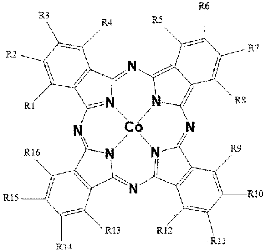 - R1 to R16 are independently selected from the groups consisting of H, F, +N(C1-C4 alkyl)3 group, or- one or several of the specific following R1, R4, R5, R8, R9, R12, R13 and R16 groups being a phenyl group bearing +N(C1-C4 alkyl)3 substituent in ortho position, the others groups among R1 to R16 being H;- Or the compound of formula:
 - a power supply (5) providing the energy necessary to trigger the electrochemical reactions involving the reagent.
 - The electrochemical system (1) according to claim 1, wherein the molecular catalyst (4B) comprises at least 1 and at most 8 groups among R1 to R16 being independently +N(C1-C4 alkyl)3, and the other groups among R1 to R16 are H .
- The electrochemical system (1) according to claim 1, wherein the molecular catalyst (4B) comprises at least 1 to 16 groups among R1 to R16 being independently F, and the other groups among R1 to R16 are H.
- The electrochemical system (1) according to claim 1, wherein the molecular catalyst (4B) is a cobalt phthalocyanine CoPc of formula :

- The electrochemical system (1) according to anyone of claim 1 or 2, wherein the molecular catalyst 4B is a cobalt phthalocyanine CoPc3 of formula:

- The electrochemical system (1) according to anyone of claims 1 to 5, wherein the solvent (3) has a pH between 12 and 13.
- The electrochemical system (1) according to anyone of claims 1 to 6, wherein the electrochemical system is a flow cell to electrochemically reduce a gas reactant comprising CO, passing through a gas diffusion electrode (19), into methanol wherein :- said anodic compartment comprises:• the anode with a current collector, and on the current collector, at least one molecular catalyst (12) to electrochemically oxidize H2O to O2,• the anodic electrolyte solution (13), at a controlled flow rate Qa, comprising: the solvent, and the anodic electrolyte, the solvent being water at a pH between 10.5 and 13.5,• an anodic electrolyte solution inlet (14) and an anodic electrolyte solution outlet (15) connected to the anodic compartment, to circulate the anodic electrolyte solution (13);- said cathodic compartment comprises:• the cathodic electrolyte solution (16), at a controlled flow rate Qc, comprising: the solvent, and the cathodic electrolyte, the solvent being water at a pH between 10.5 and 13.5,• a cathodic electrolyte solution inlet (17) and a cathodic electrolyte solution outlet (18) connected to the cathodic compartment, to circulate the cathodic electrolyte solution, and the remaining reagent gas CO and the methanol by the outlet ;• a gas diffusion electrode (19) comprising on an electrochemically inert gas diffusion porous current collector of surface S, at least the molecular catalyst (19a), as described in any of claim 1 to 6,to electrochemically reduce the gas reactant comprising CO into methanol in the cathodic electrolyte solution, with by-production of gaseous H2,- an anion exchange membrane (20), impermeable to CO, H2 and O2, between the anodic compartment and the cathodic compartment;- a channel (21) for passing the reagent gas CO, at a controlled flow rate Qg, through the porous surface S of the gas diffusion electrode (19), while the catholyte electrolyte solution circulates in between the gas diffusion electrode (19) and the anion exchange membrane (20);- pumping means serving to:• Circulate by pumping the anodic electrolyte solution in the anodic compartment and the cathodic electrolyte solution (16) in the cathodic compartment between the inlet (17) and the outlet (18),• Control flow by pumping the comprising gas CO in the channel (21), passing through the gas diffusion porous cathode (19).
- The electrochemical system (1) according to anyone of claims 1 to 7, wherein the cathode (4) comprises on the current collector (4A), an electrode film deposit which contains: the molecular catalyst (4B), at least a binder, and optionally conductive materials as additives.
- The electrochemical system (1) according to claim 8, wherein the molecular catalyst (4B) in the electrode film deposit is in a concentration of between 1 nmol.cm-2 and 100 µmol.cm-2.
- The electrochemical system (1) according to anyone of claims 8 or 9, wherein the cathodic current collector (4A) is carbon paper, the binder is Nafion© resin, the conductive material (additives) are made of carbon nanotubes, or carbon powder, or reduced graphene oxide or graphite powder.
- Electrochemical device to electrochemically reduce CO2 into methanol and deliver by-product gaseous H2, comprising:- a first electrochemical system (1') to electrochemically reduce CO2 into CO with a molecular catalyst, and- a second electrochemical system (1) to electrochemically reduce CO into methanol and gaseous H2, according to any one of claims 1 to 11.
- The electrochemical device according to claim 11, wherein the first electrochemical system (1') to electrochemically reduce CO2 into CO, comprising an electrochemical cell with:- an anodic compartment with:• an anode (2') with a current collector (2A'), and on the current collector (2A'), at least a catalyst (2B') to electrochemically oxidize H2O,• an anodic electrolyte solution comprising a solvent (3'), and an anodic supporting electrolyte, the solvent (3') being water at a pH of between 4 and 14;- a cathodic compartment with:• a cathodic electrolyte solution comprising the solvent (3'), and a cathodic supporting electrolyte, the solvent (3') being water at a pH of between 10.5 and 13.5;• the reagent CO2;• a cathode (4') which comprises, on a current collector (4A'), at least a molecular catalyst (4B') to electrochemically reduce CO2 into CO, with the formula:
 - R1 to R16 are independently selected from the groups consisting of H, F or +N(C1-C4 alkyl)3 or- one or several of the specific following R1, R4, R5, R8, R9, R12, R13 and R16 group being a phenyl group bearing +N(C1-C4 alkyl)3 substituent in ortho position, the others Ri being H;- a power supply (5) providing the energy necessary to trigger the electrochemical reactions involving the reagent;
 - The electrochemical device according to claims 11-12, wherein the first electrochemical system (1') to electrochemically reduce CO2 into CO, presents the same molecular catalyst (4B') than the molecular catalyst (4B) of the second electrochemical system (1) to electrochemically reduce CO into methanol and gaseous H2, according to claims 1-10.
Applications Claiming Priority (2)
| Application Number | Priority Date | Filing Date | Title |
|---|---|---|---|
| EP19305530.8A EP3730673A1 (en) | 2019-04-24 | 2019-04-24 | Electrochemical system for the selective reduction of carbon monoxide into methanol |
| PCT/EP2020/061554 WO2020216946A1 (en) | 2019-04-24 | 2020-04-24 | Electrochemical system for the selective reduction of carbon monoxide into methanol |
Publications (3)
| Publication Number | Publication Date |
|---|---|
| EP3959359A1 EP3959359A1 (en) | 2022-03-02 |
| EP3959359B1 true EP3959359B1 (en) | 2024-03-20 |
| EP3959359C0 EP3959359C0 (en) | 2024-03-20 |
Family
ID=66439968
Family Applications (2)
| Application Number | Title | Priority Date | Filing Date |
|---|---|---|---|
| EP19305530.8A Withdrawn EP3730673A1 (en) | 2019-04-24 | 2019-04-24 | Electrochemical system for the selective reduction of carbon monoxide into methanol |
| EP20719666.8A Active EP3959359B1 (en) | 2019-04-24 | 2020-04-24 | Electrochemical system for the selective reduction of carbon monoxide into methanol |
Family Applications Before (1)
| Application Number | Title | Priority Date | Filing Date |
|---|---|---|---|
| EP19305530.8A Withdrawn EP3730673A1 (en) | 2019-04-24 | 2019-04-24 | Electrochemical system for the selective reduction of carbon monoxide into methanol |
Country Status (4)
| Country | Link |
|---|---|
| US (1) | US12247306B2 (en) |
| EP (2) | EP3730673A1 (en) |
| ES (1) | ES2984925T3 (en) |
| WO (1) | WO2020216946A1 (en) |
Families Citing this family (5)
| Publication number | Priority date | Publication date | Assignee | Title |
|---|---|---|---|---|
| WO2023244837A2 (en) * | 2022-06-16 | 2023-12-21 | University Of Southern California | Electrocatalytic co2 or co reduction |
| CN115650990B (en) * | 2022-10-31 | 2024-03-19 | 常州大学 | Fluorine-containing near infrared absorption cationic phthalocyanine and preparation method thereof |
| CN115960040B (en) * | 2022-12-22 | 2025-03-14 | 东莞理工学院 | A cyano-modified tetrapyridine cobalt complex and its preparation method and application |
| JP2024117064A (en) * | 2023-02-16 | 2024-08-28 | 株式会社豊田中央研究所 | Electrochemical reactor, manufacturing method of cathode catalyst and dispersion liquid |
| EP4545682A1 (en) | 2023-10-26 | 2025-04-30 | Université Paris Cité | Photo-electrochemical device |
Family Cites Families (7)
| Publication number | Priority date | Publication date | Assignee | Title |
|---|---|---|---|---|
| WO2015139136A1 (en) * | 2014-03-19 | 2015-09-24 | Brereton Clive M H | Co2 electro-reduction process |
| DE102015213947A1 (en) * | 2015-07-23 | 2017-01-26 | Siemens Aktiengesellschaft | Reduction process for electrochemical carbon dioxide recovery and electrolysis system with anion exchange membrane |
| JP2018034136A (en) * | 2016-09-02 | 2018-03-08 | 株式会社東芝 | CO2 reduction catalyst, CO2 reduction electrode, and CO2 reduction device |
| WO2018132937A1 (en) * | 2017-01-17 | 2018-07-26 | South University Of Science And Technology Of China | Use of metal phthalocyanine/nanocarbon hybrid catalysts for efficient electrochemical reduction of co2 |
| DE102017204096A1 (en) * | 2017-03-13 | 2018-09-13 | Siemens Aktiengesellschaft | Production of gas diffusion electrodes with ion transport resins for the electrochemical reduction of CO2 to chemical recyclables |
| US20190055656A1 (en) * | 2017-08-16 | 2019-02-21 | The Board Of Trustees Of The University Of Illinois | Methods for the electroreduction of carbon dioxide to value added chemicals |
| US11643736B2 (en) * | 2018-10-01 | 2023-05-09 | National Institute Of Advanced Industrial Science And Technology | Electrochemical catalyst, assembly, electrochemical reactor, hydrocarbon generation system and method for generating hydrocarbon |
-
2019
- 2019-04-24 EP EP19305530.8A patent/EP3730673A1/en not_active Withdrawn
-
2020
- 2020-04-24 WO PCT/EP2020/061554 patent/WO2020216946A1/en not_active Ceased
- 2020-04-24 ES ES20719666T patent/ES2984925T3/en active Active
- 2020-04-24 EP EP20719666.8A patent/EP3959359B1/en active Active
- 2020-04-24 US US17/605,600 patent/US12247306B2/en active Active
Also Published As
| Publication number | Publication date |
|---|---|
| US12247306B2 (en) | 2025-03-11 |
| EP3730673A1 (en) | 2020-10-28 |
| EP3959359A1 (en) | 2022-03-02 |
| EP3959359C0 (en) | 2024-03-20 |
| US20220228274A1 (en) | 2022-07-21 |
| ES2984925T3 (en) | 2024-10-31 |
| WO2020216946A1 (en) | 2020-10-29 |
Similar Documents
| Publication | Publication Date | Title |
|---|---|---|
| US12247306B2 (en) | Electrochemical system for the selective reduction of carbon monoxide into methanol | |
| Ye et al. | Elucidating the activity, mechanism and application of selective electrosynthesis of ammonia from nitrate on cobalt phosphide | |
| KR102186440B1 (en) | Electrochemical Ammonia Synthesis Method Using Recycling Process | |
| Lee et al. | Cyclic two-step electrolysis for stable electrochemical conversion of carbon dioxide to formate | |
| Kuhl et al. | New insights into the electrochemical reduction of carbon dioxide on metallic copper surfaces | |
| Bertheussen et al. | Electroreduction of CO on polycrystalline copper at low overpotentials | |
| US20180023198A1 (en) | Reduction Method And Electrolysis System For Electrochemical Carbon Dioxide Utilization | |
| Joya et al. | Atomically monodisperse nickel nanoclusters as highly active electrocatalysts for water oxidation | |
| US12134826B2 (en) | CO2 electroreduction to multi-carbon products in strong acid | |
| Shrestha et al. | Boosting energy-efficient hydrogen evolution by electronically modulating Ni nodes in a framework for methanol oxidation in fresh and seawater | |
| US20170297913A1 (en) | Hydrogen Generation | |
| US20160289849A1 (en) | Bifunctional water splitting catalysts and associated methods | |
| Xu et al. | In situ cofactor regeneration enables selective CO2 reduction in a stable and efficient enzymatic photoelectrochemical cell | |
| US20190055656A1 (en) | Methods for the electroreduction of carbon dioxide to value added chemicals | |
| EP3770302B1 (en) | Iron and cobalt molecular complexes for the selective electrochemical reduction of co2 into co, with flow cells | |
| US20220411943A1 (en) | Process for the Electrochemical Synthesis of Green Urea, an Electrochemical Cell for the Electrochemical Synthesis of Green Urea and the Green Urea Produced Thereby | |
| US20260078507A1 (en) | Copper catalysts for the electrochemical conversion of carbon dioxide or carbon monoxide to c2+ products | |
| Bose et al. | Electrochemical conversion of CO2 to C2 oxygenates on Pb (II)-salen catalysts-coated graphite electrodes: role of salen ligand and appended ligand-substituents to the production | |
| Greenwell et al. | Noncovalent immobilization of a nickel cyclam catalyst on carbon electrodes for CO2 reduction using aqueous electrolyte | |
| Guenani et al. | Room temperature hydrogen production via electro-dehydrogenation of amines into nitriles: advancements in liquid organic hydrogen carriers | |
| Ibrahim et al. | Electrocatalytic hydrogen generation using tripod containing pyrazolylborate-based copper (II), nickel (II), and iron (III) complexes loaded on a glassy carbon electrode | |
| US20250163589A1 (en) | Method for the electrochemical synthesis of ammonia and installation for carrying out the method | |
| Shawabkeh et al. | Electrochemical reduction of carbon dioxide to hydrocarbons: techniques and methods | |
| Lu et al. | Both CoP/NF and CuCoP/NF electrodes prepared by a one-step method for efficient electrocatalytic glucose oxidation coupled with hydrogen evolution | |
| CN116356357B (en) | For electrochemical coupling CO-reduction of CO2And NO3-Process for preparing catalyst for urea production |
Legal Events
| Date | Code | Title | Description |
|---|---|---|---|
| STAA | Information on the status of an ep patent application or granted ep patent |
Free format text: STATUS: UNKNOWN |
|
| STAA | Information on the status of an ep patent application or granted ep patent |
Free format text: STATUS: THE INTERNATIONAL PUBLICATION HAS BEEN MADE |
|
| PUAI | Public reference made under article 153(3) epc to a published international application that has entered the european phase |
Free format text: ORIGINAL CODE: 0009012 |
|
| STAA | Information on the status of an ep patent application or granted ep patent |
Free format text: STATUS: REQUEST FOR EXAMINATION WAS MADE |
|
| 17P | Request for examination filed |
Effective date: 20211108 |
|
| AK | Designated contracting states |
Kind code of ref document: A1 Designated state(s): AL AT BE BG CH CY CZ DE DK EE ES FI FR GB GR HR HU IE IS IT LI LT LU LV MC MK MT NL NO PL PT RO RS SE SI SK SM TR |
|
| DAV | Request for validation of the european patent (deleted) | ||
| DAX | Request for extension of the european patent (deleted) | ||
| RAP3 | Party data changed (applicant data changed or rights of an application transferred) |
Owner name: CENTRE NATIONAL DE LA RECHERCHE SCIENTIFIQUE Owner name: UNIVERSITE PARIS CITE |
|
| REG | Reference to a national code |
Ref country code: DE Ref legal event code: R079 Free format text: PREVIOUS MAIN CLASS: C25B0001000000 Ipc: C25B0001010000 Ref document number: 602020027501 Country of ref document: DE |
|
| GRAP | Despatch of communication of intention to grant a patent |
Free format text: ORIGINAL CODE: EPIDOSNIGR1 |
|
| STAA | Information on the status of an ep patent application or granted ep patent |
Free format text: STATUS: GRANT OF PATENT IS INTENDED |
|
| RIC1 | Information provided on ipc code assigned before grant |
Ipc: C25B 3/26 20210101ALI20231114BHEP Ipc: C25B 11/085 20210101ALI20231114BHEP Ipc: C25B 11/032 20210101ALI20231114BHEP Ipc: C25B 9/05 20210101ALI20231114BHEP Ipc: C25B 3/25 20210101ALI20231114BHEP Ipc: C25B 3/20 20210101ALI20231114BHEP Ipc: C25B 3/07 20210101ALI20231114BHEP Ipc: C25B 1/04 20210101ALI20231114BHEP Ipc: C25B 1/01 20210101AFI20231114BHEP |
|
| INTG | Intention to grant announced |
Effective date: 20231128 |
|
| GRAS | Grant fee paid |
Free format text: ORIGINAL CODE: EPIDOSNIGR3 |
|
| GRAA | (expected) grant |
Free format text: ORIGINAL CODE: 0009210 |
|
| STAA | Information on the status of an ep patent application or granted ep patent |
Free format text: STATUS: THE PATENT HAS BEEN GRANTED |
|
| AK | Designated contracting states |
Kind code of ref document: B1 Designated state(s): AL AT BE BG CH CY CZ DE DK EE ES FI FR GB GR HR HU IE IS IT LI LT LU LV MC MK MT NL NO PL PT RO RS SE SI SK SM TR |
|
| REG | Reference to a national code |
Ref country code: GB Ref legal event code: FG4D |
|
| REG | Reference to a national code |
Ref country code: CH Ref legal event code: EP |
|
| REG | Reference to a national code |
Ref country code: DE Ref legal event code: R096 Ref document number: 602020027501 Country of ref document: DE |
|
| REG | Reference to a national code |
Ref country code: IE Ref legal event code: FG4D |
|
| U01 | Request for unitary effect filed |
Effective date: 20240410 |
|
| U07 | Unitary effect registered |
Designated state(s): AT BE BG DE DK EE FI FR IT LT LU LV MT NL PT SE SI Effective date: 20240419 |
|
| PG25 | Lapsed in a contracting state [announced via postgrant information from national office to epo] |
Ref country code: GR Free format text: LAPSE BECAUSE OF FAILURE TO SUBMIT A TRANSLATION OF THE DESCRIPTION OR TO PAY THE FEE WITHIN THE PRESCRIBED TIME-LIMIT Effective date: 20240621 |
|
| PG25 | Lapsed in a contracting state [announced via postgrant information from national office to epo] |
Ref country code: RS Free format text: LAPSE BECAUSE OF FAILURE TO SUBMIT A TRANSLATION OF THE DESCRIPTION OR TO PAY THE FEE WITHIN THE PRESCRIBED TIME-LIMIT Effective date: 20240620 Ref country code: HR Free format text: LAPSE BECAUSE OF FAILURE TO SUBMIT A TRANSLATION OF THE DESCRIPTION OR TO PAY THE FEE WITHIN THE PRESCRIBED TIME-LIMIT Effective date: 20240320 |
|
| PG25 | Lapsed in a contracting state [announced via postgrant information from national office to epo] |
Ref country code: RS Free format text: LAPSE BECAUSE OF FAILURE TO SUBMIT A TRANSLATION OF THE DESCRIPTION OR TO PAY THE FEE WITHIN THE PRESCRIBED TIME-LIMIT Effective date: 20240620 Ref country code: NO Free format text: LAPSE BECAUSE OF FAILURE TO SUBMIT A TRANSLATION OF THE DESCRIPTION OR TO PAY THE FEE WITHIN THE PRESCRIBED TIME-LIMIT Effective date: 20240620 Ref country code: HR Free format text: LAPSE BECAUSE OF FAILURE TO SUBMIT A TRANSLATION OF THE DESCRIPTION OR TO PAY THE FEE WITHIN THE PRESCRIBED TIME-LIMIT Effective date: 20240320 Ref country code: GR Free format text: LAPSE BECAUSE OF FAILURE TO SUBMIT A TRANSLATION OF THE DESCRIPTION OR TO PAY THE FEE WITHIN THE PRESCRIBED TIME-LIMIT Effective date: 20240621 |
|
| U20 | Renewal fee for the european patent with unitary effect paid |
Year of fee payment: 5 Effective date: 20240717 |
|
| PG25 | Lapsed in a contracting state [announced via postgrant information from national office to epo] |
Ref country code: IS Free format text: LAPSE BECAUSE OF FAILURE TO SUBMIT A TRANSLATION OF THE DESCRIPTION OR TO PAY THE FEE WITHIN THE PRESCRIBED TIME-LIMIT Effective date: 20240720 |
|
| PG25 | Lapsed in a contracting state [announced via postgrant information from national office to epo] |
Ref country code: SM Free format text: LAPSE BECAUSE OF FAILURE TO SUBMIT A TRANSLATION OF THE DESCRIPTION OR TO PAY THE FEE WITHIN THE PRESCRIBED TIME-LIMIT Effective date: 20240320 |
|
| PG25 | Lapsed in a contracting state [announced via postgrant information from national office to epo] |
Ref country code: CZ Free format text: LAPSE BECAUSE OF FAILURE TO SUBMIT A TRANSLATION OF THE DESCRIPTION OR TO PAY THE FEE WITHIN THE PRESCRIBED TIME-LIMIT Effective date: 20240320 |
|
| PG25 | Lapsed in a contracting state [announced via postgrant information from national office to epo] |
Ref country code: PL Free format text: LAPSE BECAUSE OF FAILURE TO SUBMIT A TRANSLATION OF THE DESCRIPTION OR TO PAY THE FEE WITHIN THE PRESCRIBED TIME-LIMIT Effective date: 20240320 |
|
| PG25 | Lapsed in a contracting state [announced via postgrant information from national office to epo] |
Ref country code: SK Free format text: LAPSE BECAUSE OF FAILURE TO SUBMIT A TRANSLATION OF THE DESCRIPTION OR TO PAY THE FEE WITHIN THE PRESCRIBED TIME-LIMIT Effective date: 20240320 |
|
| PG25 | Lapsed in a contracting state [announced via postgrant information from national office to epo] |
Ref country code: SM Free format text: LAPSE BECAUSE OF FAILURE TO SUBMIT A TRANSLATION OF THE DESCRIPTION OR TO PAY THE FEE WITHIN THE PRESCRIBED TIME-LIMIT Effective date: 20240320 Ref country code: SK Free format text: LAPSE BECAUSE OF FAILURE TO SUBMIT A TRANSLATION OF THE DESCRIPTION OR TO PAY THE FEE WITHIN THE PRESCRIBED TIME-LIMIT Effective date: 20240320 Ref country code: RO Free format text: LAPSE BECAUSE OF FAILURE TO SUBMIT A TRANSLATION OF THE DESCRIPTION OR TO PAY THE FEE WITHIN THE PRESCRIBED TIME-LIMIT Effective date: 20240320 Ref country code: PL Free format text: LAPSE BECAUSE OF FAILURE TO SUBMIT A TRANSLATION OF THE DESCRIPTION OR TO PAY THE FEE WITHIN THE PRESCRIBED TIME-LIMIT Effective date: 20240320 Ref country code: IS Free format text: LAPSE BECAUSE OF FAILURE TO SUBMIT A TRANSLATION OF THE DESCRIPTION OR TO PAY THE FEE WITHIN THE PRESCRIBED TIME-LIMIT Effective date: 20240720 Ref country code: CZ Free format text: LAPSE BECAUSE OF FAILURE TO SUBMIT A TRANSLATION OF THE DESCRIPTION OR TO PAY THE FEE WITHIN THE PRESCRIBED TIME-LIMIT Effective date: 20240320 |
|
| REG | Reference to a national code |
Ref country code: ES Ref legal event code: FG2A Ref document number: 2984925 Country of ref document: ES Kind code of ref document: T3 Effective date: 20241031 |
|
| REG | Reference to a national code |
Ref country code: DE Ref legal event code: R097 Ref document number: 602020027501 Country of ref document: DE |
|
| PG25 | Lapsed in a contracting state [announced via postgrant information from national office to epo] |
Ref country code: MC Free format text: LAPSE BECAUSE OF FAILURE TO SUBMIT A TRANSLATION OF THE DESCRIPTION OR TO PAY THE FEE WITHIN THE PRESCRIBED TIME-LIMIT Effective date: 20240320 |
|
| PLBE | No opposition filed within time limit |
Free format text: ORIGINAL CODE: 0009261 |
|
| STAA | Information on the status of an ep patent application or granted ep patent |
Free format text: STATUS: NO OPPOSITION FILED WITHIN TIME LIMIT |
|
| PG25 | Lapsed in a contracting state [announced via postgrant information from national office to epo] |
Ref country code: MC Free format text: LAPSE BECAUSE OF FAILURE TO SUBMIT A TRANSLATION OF THE DESCRIPTION OR TO PAY THE FEE WITHIN THE PRESCRIBED TIME-LIMIT Effective date: 20240320 |
|
| 26N | No opposition filed |
Effective date: 20241223 |
|
| U20 | Renewal fee for the european patent with unitary effect paid |
Year of fee payment: 6 Effective date: 20250325 |
|
| PG25 | Lapsed in a contracting state [announced via postgrant information from national office to epo] |
Ref country code: CY Free format text: LAPSE BECAUSE OF FAILURE TO SUBMIT A TRANSLATION OF THE DESCRIPTION OR TO PAY THE FEE WITHIN THE PRESCRIBED TIME-LIMIT; INVALID AB INITIO Effective date: 20200424 |
|
| PG25 | Lapsed in a contracting state [announced via postgrant information from national office to epo] |
Ref country code: HU Free format text: LAPSE BECAUSE OF FAILURE TO SUBMIT A TRANSLATION OF THE DESCRIPTION OR TO PAY THE FEE WITHIN THE PRESCRIBED TIME-LIMIT; INVALID AB INITIO Effective date: 20200424 |
|
| PGFP | Annual fee paid to national office [announced via postgrant information from national office to epo] |
Ref country code: IE Payment date: 20260323 Year of fee payment: 7 |
|
| U20 | Renewal fee for the european patent with unitary effect paid |
Year of fee payment: 7 Effective date: 20260326 |
|
| REG | Reference to a national code |
Ref country code: CH Ref legal event code: U11 Free format text: ST27 STATUS EVENT CODE: U-0-0-U10-U11 (AS PROVIDED BY THE NATIONAL OFFICE) Effective date: 20260504 |
|
| PG25 | Lapsed in a contracting state [announced via postgrant information from national office to epo] |
Ref country code: TR Free format text: LAPSE BECAUSE OF FAILURE TO SUBMIT A TRANSLATION OF THE DESCRIPTION OR TO PAY THE FEE WITHIN THE PRESCRIBED TIME-LIMIT Effective date: 20240320 |
|
| PGFP | Annual fee paid to national office [announced via postgrant information from national office to epo] |
Ref country code: ES Payment date: 20260513 Year of fee payment: 7 |
|
| PGFP | Annual fee paid to national office [announced via postgrant information from national office to epo] |
Ref country code: GB Payment date: 20260430 Year of fee payment: 7 |
|
| PGFP | Annual fee paid to national office [announced via postgrant information from national office to epo] |
Ref country code: CH Payment date: 20260504 Year of fee payment: 7 |