EP3958649A1 - Elektrische heizvorrichtung und verfahren zu deren herstellung - Google Patents
Elektrische heizvorrichtung und verfahren zu deren herstellung Download PDFInfo
- Publication number
- EP3958649A1 EP3958649A1 EP21190356.2A EP21190356A EP3958649A1 EP 3958649 A1 EP3958649 A1 EP 3958649A1 EP 21190356 A EP21190356 A EP 21190356A EP 3958649 A1 EP3958649 A1 EP 3958649A1
- Authority
- EP
- European Patent Office
- Prior art keywords
- housing
- heating device
- chamber
- heating
- partition
- Prior art date
- Legal status (The legal status is an assumption and is not a legal conclusion. Google has not performed a legal analysis and makes no representation as to the accuracy of the status listed.)
- Granted
Links
Images


Classifications
-
- H—ELECTRICITY
- H05—ELECTRIC TECHNIQUES NOT OTHERWISE PROVIDED FOR
- H05B—ELECTRIC HEATING; ELECTRIC LIGHT SOURCES NOT OTHERWISE PROVIDED FOR; CIRCUIT ARRANGEMENTS FOR ELECTRIC LIGHT SOURCES, IN GENERAL
- H05B3/00—Ohmic-resistance heating
- H05B3/40—Heating elements having the shape of rods or tubes
- H05B3/42—Heating elements having the shape of rods or tubes non-flexible
- H05B3/48—Heating elements having the shape of rods or tubes non-flexible heating conductor embedded in insulating material
- H05B3/50—Heating elements having the shape of rods or tubes non-flexible heating conductor embedded in insulating material heating conductor arranged in metal tubes, the radiating surface having heat-conducting fins
-
- B—PERFORMING OPERATIONS; TRANSPORTING
- B60—VEHICLES IN GENERAL
- B60H—ARRANGEMENTS OF HEATING, COOLING, VENTILATING OR OTHER AIR-TREATING DEVICES SPECIALLY ADAPTED FOR PASSENGER OR GOODS SPACES OF VEHICLES
- B60H1/00—Heating, cooling or ventilating devices
- B60H1/22—Heating, cooling or ventilating devices the heat source being other than the propulsion plant
- B60H1/2215—Heating, cooling or ventilating devices the heat source being other than the propulsion plant the heat being derived from electric heaters
- B60H1/2221—Heating, cooling or ventilating devices the heat source being other than the propulsion plant the heat being derived from electric heaters arrangements of electric heaters for heating an intermediate liquid
-
- F—MECHANICAL ENGINEERING; LIGHTING; HEATING; WEAPONS; BLASTING
- F24—HEATING; RANGES; VENTILATING
- F24H—FLUID HEATERS, e.g. WATER OR AIR HEATERS, HAVING HEAT-GENERATING MEANS, e.g. HEAT PUMPS, IN GENERAL
- F24H1/00—Water heaters, e.g. boilers, continuous-flow heaters or water-storage heaters
- F24H1/0072—Special adaptations
- F24H1/009—Special adaptations for vehicle systems
-
- F—MECHANICAL ENGINEERING; LIGHTING; HEATING; WEAPONS; BLASTING
- F24—HEATING; RANGES; VENTILATING
- F24H—FLUID HEATERS, e.g. WATER OR AIR HEATERS, HAVING HEAT-GENERATING MEANS, e.g. HEAT PUMPS, IN GENERAL
- F24H1/00—Water heaters, e.g. boilers, continuous-flow heaters or water-storage heaters
- F24H1/10—Continuous-flow heaters, i.e. heaters in which heat is generated only while the water is flowing, e.g. with direct contact of the water with the heating medium
- F24H1/101—Continuous-flow heaters, i.e. heaters in which heat is generated only while the water is flowing, e.g. with direct contact of the water with the heating medium using electric energy supply
- F24H1/102—Continuous-flow heaters, i.e. heaters in which heat is generated only while the water is flowing, e.g. with direct contact of the water with the heating medium using electric energy supply with resistance
-
- F—MECHANICAL ENGINEERING; LIGHTING; HEATING; WEAPONS; BLASTING
- F24—HEATING; RANGES; VENTILATING
- F24H—FLUID HEATERS, e.g. WATER OR AIR HEATERS, HAVING HEAT-GENERATING MEANS, e.g. HEAT PUMPS, IN GENERAL
- F24H1/00—Water heaters, e.g. boilers, continuous-flow heaters or water-storage heaters
- F24H1/10—Continuous-flow heaters, i.e. heaters in which heat is generated only while the water is flowing, e.g. with direct contact of the water with the heating medium
- F24H1/12—Continuous-flow heaters, i.e. heaters in which heat is generated only while the water is flowing, e.g. with direct contact of the water with the heating medium in which the water is kept separate from the heating medium
- F24H1/121—Continuous-flow heaters, i.e. heaters in which heat is generated only while the water is flowing, e.g. with direct contact of the water with the heating medium in which the water is kept separate from the heating medium using electric energy supply
-
- F—MECHANICAL ENGINEERING; LIGHTING; HEATING; WEAPONS; BLASTING
- F24—HEATING; RANGES; VENTILATING
- F24H—FLUID HEATERS, e.g. WATER OR AIR HEATERS, HAVING HEAT-GENERATING MEANS, e.g. HEAT PUMPS, IN GENERAL
- F24H3/00—Air heaters
- F24H3/02—Air heaters with forced circulation
- F24H3/04—Air heaters with forced circulation the air being in direct contact with the heating medium, e.g. electric heating element
- F24H3/0405—Air heaters with forced circulation the air being in direct contact with the heating medium, e.g. electric heating element using electric energy supply, e.g. the heating medium being a resistive element; Heating by direct contact, i.e. with resistive elements, electrodes and fins being bonded together without additional element in-between
- F24H3/0429—For vehicles
-
- F—MECHANICAL ENGINEERING; LIGHTING; HEATING; WEAPONS; BLASTING
- F24—HEATING; RANGES; VENTILATING
- F24H—FLUID HEATERS, e.g. WATER OR AIR HEATERS, HAVING HEAT-GENERATING MEANS, e.g. HEAT PUMPS, IN GENERAL
- F24H9/00—Details
- F24H9/20—Arrangement or mounting of control or safety devices
- F24H9/2007—Arrangement or mounting of control or safety devices for water heaters
- F24H9/2014—Arrangement or mounting of control or safety devices for water heaters using electrical energy supply
-
- F—MECHANICAL ENGINEERING; LIGHTING; HEATING; WEAPONS; BLASTING
- F24—HEATING; RANGES; VENTILATING
- F24H—FLUID HEATERS, e.g. WATER OR AIR HEATERS, HAVING HEAT-GENERATING MEANS, e.g. HEAT PUMPS, IN GENERAL
- F24H9/00—Details
- F24H9/20—Arrangement or mounting of control or safety devices
- F24H9/2064—Arrangement or mounting of control or safety devices for air heaters
- F24H9/2071—Arrangement or mounting of control or safety devices for air heaters using electrical energy supply
-
- H—ELECTRICITY
- H05—ELECTRIC TECHNIQUES NOT OTHERWISE PROVIDED FOR
- H05B—ELECTRIC HEATING; ELECTRIC LIGHT SOURCES NOT OTHERWISE PROVIDED FOR; CIRCUIT ARRANGEMENTS FOR ELECTRIC LIGHT SOURCES, IN GENERAL
- H05B1/00—Details of electric heating devices
- H05B1/02—Automatic switching arrangements specially adapted to apparatus ; Control of heating devices
- H05B1/0227—Applications
- H05B1/023—Industrial applications
- H05B1/0236—Industrial applications for vehicles
-
- H—ELECTRICITY
- H05—ELECTRIC TECHNIQUES NOT OTHERWISE PROVIDED FOR
- H05B—ELECTRIC HEATING; ELECTRIC LIGHT SOURCES NOT OTHERWISE PROVIDED FOR; CIRCUIT ARRANGEMENTS FOR ELECTRIC LIGHT SOURCES, IN GENERAL
- H05B1/00—Details of electric heating devices
- H05B1/02—Automatic switching arrangements specially adapted to apparatus ; Control of heating devices
- H05B1/0227—Applications
- H05B1/023—Industrial applications
- H05B1/0244—Heating of fluids
-
- H—ELECTRICITY
- H05—ELECTRIC TECHNIQUES NOT OTHERWISE PROVIDED FOR
- H05B—ELECTRIC HEATING; ELECTRIC LIGHT SOURCES NOT OTHERWISE PROVIDED FOR; CIRCUIT ARRANGEMENTS FOR ELECTRIC LIGHT SOURCES, IN GENERAL
- H05B3/00—Ohmic-resistance heating
- H05B3/02—Details
-
- H—ELECTRICITY
- H05—ELECTRIC TECHNIQUES NOT OTHERWISE PROVIDED FOR
- H05B—ELECTRIC HEATING; ELECTRIC LIGHT SOURCES NOT OTHERWISE PROVIDED FOR; CIRCUIT ARRANGEMENTS FOR ELECTRIC LIGHT SOURCES, IN GENERAL
- H05B3/00—Ohmic-resistance heating
- H05B3/02—Details
- H05B3/03—Electrodes
-
- H—ELECTRICITY
- H05—ELECTRIC TECHNIQUES NOT OTHERWISE PROVIDED FOR
- H05B—ELECTRIC HEATING; ELECTRIC LIGHT SOURCES NOT OTHERWISE PROVIDED FOR; CIRCUIT ARRANGEMENTS FOR ELECTRIC LIGHT SOURCES, IN GENERAL
- H05B3/00—Ohmic-resistance heating
- H05B3/02—Details
- H05B3/04—Waterproof or air-tight seals for heaters
-
- H—ELECTRICITY
- H05—ELECTRIC TECHNIQUES NOT OTHERWISE PROVIDED FOR
- H05B—ELECTRIC HEATING; ELECTRIC LIGHT SOURCES NOT OTHERWISE PROVIDED FOR; CIRCUIT ARRANGEMENTS FOR ELECTRIC LIGHT SOURCES, IN GENERAL
- H05B3/00—Ohmic-resistance heating
- H05B3/02—Details
- H05B3/06—Heater elements structurally combined with coupling elements or holders
-
- H—ELECTRICITY
- H05—ELECTRIC TECHNIQUES NOT OTHERWISE PROVIDED FOR
- H05B—ELECTRIC HEATING; ELECTRIC LIGHT SOURCES NOT OTHERWISE PROVIDED FOR; CIRCUIT ARRANGEMENTS FOR ELECTRIC LIGHT SOURCES, IN GENERAL
- H05B3/00—Ohmic-resistance heating
- H05B3/10—Heating elements characterised by the composition or nature of the materials or by the arrangement of the conductor
- H05B3/12—Heating elements characterised by the composition or nature of the materials or by the arrangement of the conductor characterised by the composition or nature of the conductive material
- H05B3/14—Heating elements characterised by the composition or nature of the materials or by the arrangement of the conductor characterised by the composition or nature of the conductive material the material being non-metallic
- H05B3/141—Conductive ceramics, e.g. metal oxides, metal carbides, barium titanate, ferrites, zirconia, vitrous compounds
-
- H—ELECTRICITY
- H05—ELECTRIC TECHNIQUES NOT OTHERWISE PROVIDED FOR
- H05B—ELECTRIC HEATING; ELECTRIC LIGHT SOURCES NOT OTHERWISE PROVIDED FOR; CIRCUIT ARRANGEMENTS FOR ELECTRIC LIGHT SOURCES, IN GENERAL
- H05B3/00—Ohmic-resistance heating
- H05B3/10—Heating elements characterised by the composition or nature of the materials or by the arrangement of the conductor
- H05B3/12—Heating elements characterised by the composition or nature of the materials or by the arrangement of the conductor characterised by the composition or nature of the conductive material
- H05B3/14—Heating elements characterised by the composition or nature of the materials or by the arrangement of the conductor characterised by the composition or nature of the conductive material the material being non-metallic
- H05B3/146—Conductive polymers, e.g. polyethylene, thermoplastics
-
- H—ELECTRICITY
- H05—ELECTRIC TECHNIQUES NOT OTHERWISE PROVIDED FOR
- H05B—ELECTRIC HEATING; ELECTRIC LIGHT SOURCES NOT OTHERWISE PROVIDED FOR; CIRCUIT ARRANGEMENTS FOR ELECTRIC LIGHT SOURCES, IN GENERAL
- H05B3/00—Ohmic-resistance heating
- H05B3/20—Heating elements having extended surface area substantially in a two-dimensional [2D] plane, e.g. plate-heater
- H05B3/22—Heating elements having extended surface area substantially in a two-dimensional [2D] plane, e.g. plate-heater non-flexible
- H05B3/24—Heating elements having extended surface area substantially in a two-dimensional [2D] plane, e.g. plate-heater non-flexible heating conductor being self-supporting
-
- H—ELECTRICITY
- H05—ELECTRIC TECHNIQUES NOT OTHERWISE PROVIDED FOR
- H05B—ELECTRIC HEATING; ELECTRIC LIGHT SOURCES NOT OTHERWISE PROVIDED FOR; CIRCUIT ARRANGEMENTS FOR ELECTRIC LIGHT SOURCES, IN GENERAL
- H05B3/00—Ohmic-resistance heating
- H05B3/20—Heating elements having extended surface area substantially in a two-dimensional [2D] plane, e.g. plate-heater
- H05B3/22—Heating elements having extended surface area substantially in a two-dimensional [2D] plane, e.g. plate-heater non-flexible
- H05B3/32—Heating elements having extended surface area substantially in a two-dimensional [2D] plane, e.g. plate-heater non-flexible heating conductor mounted on insulators on a metallic frame
-
- H—ELECTRICITY
- H05—ELECTRIC TECHNIQUES NOT OTHERWISE PROVIDED FOR
- H05B—ELECTRIC HEATING; ELECTRIC LIGHT SOURCES NOT OTHERWISE PROVIDED FOR; CIRCUIT ARRANGEMENTS FOR ELECTRIC LIGHT SOURCES, IN GENERAL
- H05B3/00—Ohmic-resistance heating
- H05B3/78—Heating arrangements specially adapted for immersion heating
- H05B3/82—Fixedly-mounted immersion heaters
-
- B—PERFORMING OPERATIONS; TRANSPORTING
- B23—MACHINE TOOLS; METAL-WORKING NOT OTHERWISE PROVIDED FOR
- B23K—SOLDERING OR UNSOLDERING; WELDING; CLADDING OR PLATING BY SOLDERING OR WELDING; CUTTING BY APPLYING HEAT LOCALLY, e.g. FLAME CUTTING; WORKING BY LASER BEAM
- B23K1/00—Soldering, e.g. brazing, or unsoldering
- B23K1/002—Soldering by means of induction heating
-
- B—PERFORMING OPERATIONS; TRANSPORTING
- B60—VEHICLES IN GENERAL
- B60H—ARRANGEMENTS OF HEATING, COOLING, VENTILATING OR OTHER AIR-TREATING DEVICES SPECIALLY ADAPTED FOR PASSENGER OR GOODS SPACES OF VEHICLES
- B60H1/00—Heating, cooling or ventilating devices
- B60H1/22—Heating, cooling or ventilating devices the heat source being other than the propulsion plant
- B60H2001/2268—Constructional features
- B60H2001/2278—Connectors, water supply, housing, mounting brackets
-
- F—MECHANICAL ENGINEERING; LIGHTING; HEATING; WEAPONS; BLASTING
- F24—HEATING; RANGES; VENTILATING
- F24H—FLUID HEATERS, e.g. WATER OR AIR HEATERS, HAVING HEAT-GENERATING MEANS, e.g. HEAT PUMPS, IN GENERAL
- F24H2250/00—Electrical heat generating means
- F24H2250/04—Positive temperature coefficients [PTC]; Negative temperature coefficients [NTC]
-
- H—ELECTRICITY
- H05—ELECTRIC TECHNIQUES NOT OTHERWISE PROVIDED FOR
- H05B—ELECTRIC HEATING; ELECTRIC LIGHT SOURCES NOT OTHERWISE PROVIDED FOR; CIRCUIT ARRANGEMENTS FOR ELECTRIC LIGHT SOURCES, IN GENERAL
- H05B2203/00—Aspects relating to Ohmic resistive heating covered by group H05B3/00
- H05B2203/016—Heaters using particular connecting means
-
- H—ELECTRICITY
- H05—ELECTRIC TECHNIQUES NOT OTHERWISE PROVIDED FOR
- H05B—ELECTRIC HEATING; ELECTRIC LIGHT SOURCES NOT OTHERWISE PROVIDED FOR; CIRCUIT ARRANGEMENTS FOR ELECTRIC LIGHT SOURCES, IN GENERAL
- H05B2203/00—Aspects relating to Ohmic resistive heating covered by group H05B3/00
- H05B2203/017—Manufacturing methods or apparatus for heaters
-
- H—ELECTRICITY
- H05—ELECTRIC TECHNIQUES NOT OTHERWISE PROVIDED FOR
- H05B—ELECTRIC HEATING; ELECTRIC LIGHT SOURCES NOT OTHERWISE PROVIDED FOR; CIRCUIT ARRANGEMENTS FOR ELECTRIC LIGHT SOURCES, IN GENERAL
- H05B2203/00—Aspects relating to Ohmic resistive heating covered by group H05B3/00
- H05B2203/02—Heaters using heating elements having a positive temperature coefficient
-
- H—ELECTRICITY
- H05—ELECTRIC TECHNIQUES NOT OTHERWISE PROVIDED FOR
- H05B—ELECTRIC HEATING; ELECTRIC LIGHT SOURCES NOT OTHERWISE PROVIDED FOR; CIRCUIT ARRANGEMENTS FOR ELECTRIC LIGHT SOURCES, IN GENERAL
- H05B2203/00—Aspects relating to Ohmic resistive heating covered by group H05B3/00
- H05B2203/021—Heaters specially adapted for heating liquids
-
- H—ELECTRICITY
- H05—ELECTRIC TECHNIQUES NOT OTHERWISE PROVIDED FOR
- H05B—ELECTRIC HEATING; ELECTRIC LIGHT SOURCES NOT OTHERWISE PROVIDED FOR; CIRCUIT ARRANGEMENTS FOR ELECTRIC LIGHT SOURCES, IN GENERAL
- H05B2203/00—Aspects relating to Ohmic resistive heating covered by group H05B3/00
- H05B2203/022—Heaters specially adapted for heating gaseous material
- H05B2203/023—Heaters of the type used for electrically heating the air blown in a vehicle compartment by the vehicle heating system
Definitions
- the present invention relates to an electric heating device with a housing which has a partition wall which separates a connection chamber from a heating chamber for dissipating heat. At least one PTC heating device protrudes from the partition in the direction of the heating chamber. This PTC heating element is exposed in the heating chamber in the manner of a heating rib.
- the PTC heating device has at least one PTC element and conductor tracks connected thereto in an electrically conductive manner, which are assigned different polarities for energizing the PTC element. These conductor tracks are electrically connected to the power current in the connection chamber.
- Such a heater is, for example, from EP 2 337 425 A1 famous.
- the partition wall is designed in one piece with a heating device housing, which protrudes into the heating chamber as a heating rib.
- the partition wall is produced in one piece together with the heating device housing by means of die-cast aluminum. This type of manufacture requires a significant amount of aluminum.
- the electric heater is therefore relatively heavy.
- a plurality of heater housings are provided, which protrude into the heating chamber as ribs closed on the underside. For manufacturing reasons, these must be at a certain distance from one another, which runs counter to the requirement for a compact structure.
- a PTC heating element is first produced as a separate component and used as such in a heating element receptacle formed on the partition wall, so that the connection-side end of the heating element housing is sealed in the heating element receptacle of the partition wall and the conductor tracks with their free, connection-side ends in be exposed to the connection chamber in order to be electrically connected there.
- the PCT heating element pre-assembled in this way is held in the heating element receptacle with a positive fit until it is pressed in.
- This pressing recording requires a certain wall thickness on the part of the partition.
- Another problem with this configuration is the tightness between the PTC heating element and the heating element receptacle.
- a seal made of a plastic material can age at the temperatures prevailing during operation, so that there is a risk that the fluid to be heated will get out of the heating chamber and into the connection chamber.
- the electrical connection of the PTC element to the power current takes place in the connection chamber, so that with a view to operational safety, no liquid may get into the connection chamber. Otherwise a short circuit is to be feared.
- the electric heater in an electrically powered vehicle in which the vehicle electrical system voltage also to Operation of the electric heater is used, encounter such defects significant safety concerns.
- the present invention is based on the problem of specifying a compact electrical heating device and a method for producing such a device.
- an electric heating device with feature 1 is specified with the present invention.
- the present invention allows the subsequent connection of components initially made of thin sheet metal in order to define or to define the connection chamber and/or the heating chamber the partition provided between them.
- the electric heating device according to the present invention is in particular an electric heating device in a motor vehicle. Flexible hoses are usually connected to the respective connection pieces of the electrical heating device and sealed against them.
- the sheet metal can have a wall thickness of less than 1 millimeter.
- a partition wall is first provided, which will separate a connection chamber from a heating chamber on the housing, the partition wall having at least one opening for the electrical connection of the PTC element in the connection chamber.
- the PTC element can be introduced into the heating device housing from the connection chamber side through this opening.
- the heating device housing is usually closed on the underside, ie with its end lying in the heating chamber.
- the heater case can be provided in this way.
- the heating device housing is preferably formed by a piece of a cylindrical tubular body cut to length, which can be closed on the underside by deforming the sheet metal material forming the heating device housing. There, the sheet metal material can be glued, soldered, welded and/or closed by flanging or a plug inserted in a sealed manner.
- a housing wall is alternatively or additionally connected to the partition wall by means of inductive soldering, it being possible for this housing wall to completely or partially surround the connection chamber and/or the heating chamber.
- the solution according to the invention offers the possibility of a more compact construction of an electric heating device.
- the individual heating device housings can be provided on the partition at a small distance from one another.
- the inductive soldering allows a locally limited heating, so that a good dimensional accuracy of the previously manufactured components of the electrical heating device is given even after the thermal joining.
- a secure, fluid-tight connection between the partition wall and the component connected to it, for example the heating device housing or the housing wall can be achieved with inductive soldering.
- the low level of heating through of the connection partners during inductive soldering also allows local heating and thus a relatively dense arrangement of several heating device housings connected to the partition wall next to or behind one another.
- the invention accordingly allows greater degrees of freedom both in the design of the heating device housing and the housing of the entire electrical heating device. Compared to the prior art, when designing the electric heating device according to the invention, it is no longer necessary to take into account the demoulding of an aluminum housing produced by means of a die-casting process.
- connection partners are usually made of metal, preferably of a stamped metal sheet, which is usually applied to a surface of the partition wall, the heating element housing and/or the housing wall over its entire surface.
- Induction brazing leads to a full-surface and thus tight connection between the partition, the heating element housing and/or the housing wall.
- the inductive soldering can preferably be carried out in such a way that a contact element is applied to the surface of the partition wall, the heating element housing and/or the housing wall, optionally after a certain amount of preheating in order to reduce the soldering time.
- the joint is then heated by inductive heating in such a way that the solder located at the joint heats up and liquefies. Capillary forces can pull the solder between the surfaces to be joined and thus concentrate solder at the phase boundary between the two connection partners of the soldered joint.
- a ring made of a solder is preferably arranged adjacent to a gap between the connection partners and formed by the connection partners.
- An inductor is arranged on the outer circumference or inner circumference of the ring, which inductively heats the solder and the connection partners enclosing a gap between them in the region of the gap.
- the inductor is thereby switched on to define the solder and the gap To heat surfaces of the connection partner. After the solder has been reflowed, the inductor is turned off. The solder flows into the gap and solidifies there.
- connection partners can consist of or contain non-ferrous metals, ferrous metals, chromium-nickel steels and non-metallic materials as well as any combination of these materials.
- the soldering method according to the invention leads to a corrosion-resistant, in particular gas-tight and liquid-tight connection between the connection partners.
- the cycle time of the soldering process is independent of the total length of the connection.
- Different inductors can be used at the same time. In this way, soldering can be carried out at different points at the same time.
- the warming is locally limited. This offers the possibility of equipping the heater housing before soldering. However, assembly after soldering is preferable.
- Reference numeral 2 denotes a housing with a housing upper part 4 and a housing lower part 6.
- the housing upper part 4 surrounds a connection chamber 8.
- the housing lower part 6 surrounds a heating chamber 10.
- the partition wall 12 is fluid-tight, so that liquid fluid contained in the heating chamber 10 that is to be heated cannot reach the connection chamber 8 .
- the housing 2 is surmounted at the level of the heating chamber 10 by connecting pieces 14 which serve to connect fluid-carrying lines within a motor vehicle. These connecting pieces 14 protrude from opposite housing walls 16 which, in the present case, surround the heating chamber 6 circumferentially. Only one of these connecting pieces 14 can be seen in the figure, specifically in partial section.
- a heating device housing is identified by reference numeral 18, which in the present case is designed as a U-shaped pocket that is closed on the underside.
- a plurality of PTC elements 20 are arranged one above the other in the height direction of the heating device housing 18, which are arranged between contact surfaces which, as conductor tracks 22, rest in an electrically conductive manner on the respective PTC elements 20 and are formed from a sheet metal material and form closing lugs 23, which are electrically conductively connected in the connection chamber.
- Insulating layers 24 are located on the outside of the respective conductor track 22, so that heat emitted via the main side surfaces of the PTC elements first penetrates the conductor track 22 and then the insulating layer 24 and is conducted through the walls of the heating device housing 18 that protrude into the heating chamber 10 as a heating rib.
- the heater housing 18 is presently formed from a relatively thin sheet metal material. It lies without a gap on the outside of insulating layers 24 . The heater housing 18 can also be prestressed against it.
- the mass of the material forming the heating rib is significantly reduced.
- the exemplary embodiment shown can be produced with a lower weight. Also can be dispensed with a wedge element, which after EP 2 337 425 A1 is pressed into the receiving pocket in order to ensure good heat-conducting contact between the PTC element 20 and the heat-decoupling surfaces of the heating fin.
- the housing 2 also consists of a relatively thin sheet metal material. So it is the heating chamber 10 circumferentially surrounded by a basically cylindrical sheet metal collar, which is soldered to a base plate 26 of the housing 2, in particular induction soldered. The soldering point is marked with reference number 28
- the partition wall 12 is also formed from a relatively thin sheet metal material and is soldered to the inner peripheral surface of the housing 2 in a fluid-tight manner. This soldering point is also marked with reference number 28 .
- the heater housing 18 is also brazed to the bulkhead 12.
- the heating device housing 18 is introduced into an opening 30 of the partition wall 12 before it is fitted with the PTC element or elements 20 and the conductor tracks 22 and the insulating layers 24 and is soldered to the partition wall 12 in this opening.
- the connecting piece 14 is soldered to the housing wall 16 in the same way.
- the soldering point is also marked with reference number 28 here.
- the figure 2 shows a sectional view of the connection point between the partition wall 12 and the heating device housing 18.
- the partition wall 12 is provided with a projecting connecting piece 32 by deep-drawing.
- the connecting piece 32 is formed in one piece on the sheet metal part forming the partition wall 12 .
- the connecting piece 32 engages the inside of the heater housing 18 .
- figure 2 indicates a ring made of solder material with reference numeral 34, the inner diameter of which is slightly larger than the outer diameter of the heating device housing 18.
- Reference to diameter does not necessarily imply that heater housing 18 or ring 34 are shaped as circular in plan view. Rather, the ring 34 can also be polygonal, in particular rectangular in shape.
- An inductor is identified by reference numeral 36 .
- this inductor 36 for soldering is located inside a protective gas housing 38, which essentially seals against the underside of the partition wall 12 facing the heating chamber 10 on the one hand and against the outer peripheral surface of the heating device housing 18 on the other. It goes without saying that the soldering is carried out before the base plate 26 is connected to the lower housing part 6 .
- the inductor 36 is switched on for soldering, as a result of which the solder and the overlapping walls in the area of the connecting piece 32 and the heating device housing 18 are heated.
- Solder material is a high-temperature copper-based solder.
- the shielding gas housing 38 is flooded with shielding gas.
- the solder melts and flows into an in due to capillary action Figure 2b gap indicated by reference numeral 40.
- the solder is in Figure 2b identified by reference numeral 42. In the Figure 2b The solidified form of the solder 42 shown results naturally due to the volume of solder 42 used on the one hand and the capillary effect on the other.
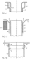
- FIG. 3 shows an alternative embodiment.
- Numeral 18 is the heater case inside; shown with reference number 32 of the connecting piece on the outside. The conditions can also be reversed, ie the connecting piece 32 can be realized with smaller dimensions than the heating device housing 18 . All that is essential is a certain length piece with an overlap.
- a solder support made of an electrically non-conductive material is identified by reference number 44 . Because of this materiality the solder support 44 is not heated by the inductor 36. Ring 34 rests on a surface of solder support 44 prior to soldering. After switching on the inductor 36 (not shown), the solder 42 flows into the gap 40 and solidifies there. A fluid-tight secure connection results between the two overlapping sections of the connecting piece 32 on the one hand and the heating device housing 18 on the other hand.
- FIG. 4 Another variant to the representation according to figure 2 is in figure 4 shown.
- the solder is in the form of the ring 34 before soldering in a beaded receiving ring 46 before soldering (left). After soldering, the solder has flowed into the gap 40. The receiving ring 46 is emptied. It should be noted that solder also flowed between the end face of the flanged receiving ring 46 and the outer peripheral surface of the heater housing 18 .
- the variant after figure 4 offers the advantage that the ring 34 can be inserted into the annular gap between the outer and inner material. The abutting parts substantially seal the receiving area for the solder 42 . This reduces environmental influences when soldering in the area of the soldering point.
- the figure 5 14 shows another variant in which the heater housing 18 is accommodated within the connecting piece 32 which is formed integrally with the partition wall 12.
- FIG. The overlapping area extends essentially over the height of the inductor 36.
- the figure below shows an edge area of the overlapping area which is identified by reference number 47 and is not covered by the effect of the inductor 36.
- the mutually opposite connection partners are accordingly colder there, so that the molten solder 42 entering from above inevitably solidifies in this area and the solder 42 is prevented from flowing out of the gap 40 .
- the solder 42 cools down - how figure 5 right indicates - at a distance from the lower end of the overlapping area.
- the figure 6 shows a variant in which the connecting piece 32 is provided on the outside and the heater housing 18 is provided on the inside.
- the heating device housing 18 is provided with a contact flange identified by reference number 48 .
- This contact flange 48 is also formed by bending sheet metal material that forms the heating device housing 18 .
- Ring 34 is in figure 6 arranged on the left in an annular gap which is delimited in the longitudinal direction of the heating device housing 18 by the contact flange 48 on the one hand and the partition wall 12 on the other.
- the ring 34 is located radially outside of the contact flange 48 before the soldering.
- the inductor 36 is ring-shaped and surrounds the contact flange 48 on the outside.
- the partition wall 12 is formed radially outside of the abutment flange 48 in the direction of the heating chamber 10 to create an annular receiving area 51 for the shaped inductor 36 .
- the figure 7 shows part of the connecting piece 14 which is provided with a widened contact flange 50 .
- the housing wall 16 has an outwardly beveled bore 52. Between the material of the housing wall 16 delimiting the bore 52 and the connecting piece 14, the ring 34 made of solder is provided. In this exemplary embodiment, too, the solder penetrates into the gap 40 between the inner surface of the housing wall 16 and the contact flange 50 as a result of the heating through the inductor 36 and due to the capillary effect.
- FIG. 8 A variant to figure 7 is in figure 8 shown.
- the lower housing part 6 is bent outwards to form a receptacle 54 with an L-shaped cross section.
- the free end of the upper housing part 4 is inserted into this L-shaped receptacle.
- the free upper end of the lower housing part 6 is provided with a funnel-shaped bulge 56 .
- this ring 34 is clamped before soldering. The solder flows into the gap marked with reference number 40 when the inductor 36 is activated.
- the figure 9 shows a variant.
- the upper housing part 4 and the lower housing part 6 each have opposing flange surfaces 58, 60.
- the flange surface 60 of the lower housing part 6 is provided with an annular circumferential recess 62 in which the ring 34 is accommodated.
- the figure 10 12 shows a further variant for connecting the heating device housing 18 to the partition wall 12.
- the partition wall 12 also has a connecting piece 32 here. However, this is formed conically tapering inwards at its free end. In a corresponding manner, the heating device housing 18 is formed conically outwards at its free end. This shaping results in a pre-positioning of the components joined in the longitudinal direction of the heating device housing 18 .
- the ring 34 is seated between the free end of the heater housing 18 and the bulkhead 12 extending thereabove prior to brazing.
Landscapes
- Engineering & Computer Science (AREA)
- Physics & Mathematics (AREA)
- Thermal Sciences (AREA)
- Mechanical Engineering (AREA)
- Chemical & Material Sciences (AREA)
- Combustion & Propulsion (AREA)
- General Engineering & Computer Science (AREA)
- Ceramic Engineering (AREA)
- General Induction Heating (AREA)
- Air-Conditioning For Vehicles (AREA)
Abstract
Description
- Die vorliegende Erfindung betrifft eine elektrische Heizvorrichtung mit einem Gehäuse, welches eine Trennwand aufweist, die eine Anschlusskammer von einer Heizkammer zur Abgabe von Wärme trennt. Von der Trennwand ragt zumindest eine PTC-Heizeinrichtung in Richtung auf die Heizkammer ab. Dieses PTC-Heizelement liegt nach Art einer Heizrippe in der Heizkammer frei. Die PTC-Heizeinrichtung hat zumindest ein PTC-Element und elektrisch leitend damit verbundene Leiterbahnen, die unterschiedlichen Polaritäten zur Bestromung des PTC-Elementes zugeordnet sind. Diese Leiterbahnen sind in der Anschlusskammer elektrisch an den Leistungsstrom angeschlossen.
- Eine derartige Heizvorrichtung ist beispielsweise aus der
EP 2 337 425 A1 bekannt. Bei einer solchen elektrischen Heizvorrichtung ist die Trennwand einteilig mit einem Heizeinrichtungsgehäuse ausgebildet, welches als Heizrippe in die Heizkammer hineinragt. Bei dem zuvor genannten Stand der Technik wird die Trennwand zusammen mit dem Heizeinrichtungsgehäuse einteilig mittels Aluminium-Druckguss hergestellt. Diese Art der Herstellung erfordert eine erhebliche Menge an Aluminium. Die elektrischen Heizvorrichtung ist daher relativ schwer. Bei der zuvor erwähnten elektrischen Heizvorrichtung sind eine Vielzahl von Heizeinrichtungsgehäusen vorgesehen, die als unterseitig geschlossene Rippen in die Heizkammer hineinragen. Herstellungsbedingt müssen diese einen gewissen Abstand zueinander aufweisen, was dem Erfordernis eines kompakten Aufbaus zuwiderläuft. - Bei der Variante nach
EP 3 334 242 A1 wird ein PTC-Heizelement zunächst als separates Bauteil hergestellten und als solches in einer Heizelementaufnahme, die an der Trennwand ausgebildet ist, eingesetzt, sodass das anschlussseitige Ende des Heizelementgehäuses abgedichtet in der Heizelementaufnahme der Trennwand aufgenommen ist und die Leiterbahnen mit ihren freien, anschlussseitigen Enden in der Anschlusskammer freiliegen, um dort elektrisch angeschlossen zu werden. Bei diesem Stand der Technik wird die so vormontierte PCT-Heizelemente formschlüssig in der Heizelementaufnahme gehalten bis eingepresst ist. - Diese verpressende Aufnahme bedingt eine gewisse Wandstärke auf Seiten der Trennwand. Problematisch bei dieser Ausgestaltung ist ferner die Dichtigkeit zwischen dem PTC-Heizelement und der Heizelementaufnahme. Bei den im Betrieb vorherrschenden Temperaturen kann eine Dichtung aus einem Kunststoffmaterial altern, sodass die Gefahr besteht, dass das zu erwärmende Fluid aus der Heizkammer in die Anschlusskammer gelangt. In der Anschlusskammer erfolgt indes der elektrische Anschluss des PTC-Elementes an den Leistungsstrom, so dass mit Blick auf die Betriebssicherheit keine Flüssigkeit in die Anschlusskammer gelangen darf. Andernfalls ist ein Kurzschluss zu befürchten. Insbesondere bei der Verwendung der elektrischen Heizvorrichtung in einem elektrisch betriebenen Fahrzeug, bei dem die Bordnetzspannung auch zum Betrieb der elektrischen Heizvorrichtung genutzt wird, begegnen solche Defekte erheblichen Sicherheitsbedenken.
- Der vorliegenden Erfindung liegt das Problem zugrunde, eine kompakt bauende elektrische Heizvorrichtung und ein Verfahren zur Herstellung einer solchen anzugeben.
- Zur Lösung des vorrichtungsmäßigen Problems wird mit der vorliegenden Erfindung eine elektrische Heizvorrichtung mit Merkmal 1 angegeben. Bei dieser elektrischen Heizvorrichtung ist eine von der Trennwand abragende Gehäusewand, die die Anschlusskammer oder die Heizkammer bzw. die Anschlusskammer und die Heizkammer begrenzende kann, induktiv mit der Trennwand verlötet. Entsprechendes gilt ergänzend oder alternativ für die Verbindung des Heizeinrichtungsgehäuses mit der Trennwand.
- Im Gegensatz zu dem zuerst diskutierten Stand der Technik, bei dem das Gehäuse und auch die Heizrippe durch Aluminiumdruckguss einteilig hergestellt werden, erlaubt die vorliegende Erfindung das nachträgliche Verbinden von zunächst aus dünnem Blech bereitgestellten Komponenten, um die Anschlusskammer und/oder die Heizkammer zu definieren bzw. die dazwischen vorgesehene Trennwand. Entsprechendes gilt für etwaige von einer Gehäusewand abragende Anschlussstutzen, beispielsweise für Fluidleitungen eines Zirkulationskreislaufs, der das in der elektrischen Heizvorrichtung zu erwärmende Fluid führt. Bei der elektrische Heizvorrichtung nach der vorliegenden Erfindung handelt es sich insbesondere um eine elektrische Heizvorrichtung in einem Kraftfahrzeug. Üblicherweise werden flexible Schläuche an die jeweiligen Anschlussstutzen der elektrischen Heizvorrichtung angeschlossen und dagegen abgedichtet.
- Das Blech kann eine Wandstärke von unter 1 Millimeter haben.
- Nach dem erfindungsgemäßen Vorgehen wird zunächst eine Trennwand bereitgestellt, die eine Anschlusskammer von einer Heizkammer an dem Gehäuse trennen wird, wobei die Trennwand zum elektrischen Anschluss des PTC-Elementes in der Anschlusskammer mindestens eine Öffnung aufweist. Durch diese Öffnung kann das PTC-Element von Seiten der Anschlusskammer in das Heizeinrichtungsgehäuse eingebracht werden. Das Heizeinrichtungsgehäuses ist üblicherweise unterseitig, d.h. mit seinem in der Heizkammer liegenden Ende verschlossen. Das Heizeinrichtungsgehäuse kann in dieser Weise bereitgestellt werden. Bevorzugt ist das Heizeinrichtungsgehäuse durch ein auf Länge abgeschnittenes Stücks eines zylindrischen Rohrkörpers gebildet, der unterseitig durch Verformen des das Heizeinrichtungsgehäuse ausbildenden Blechmaterials verschlossen sein kann. Dort kann das Blechmaterial verklebt, verlötet, verschweißt und/oder durch Umbördeln oder einen abgedichtet eingesetzten Stopfen geschlossen sein. Bei dem erfindungsgemäßen Verfahren wird alternativ oder ergänzend eine Gehäusewand mittels induktivem Löten mit der Trennwand verbunden, wobei diese Gehäusewand die Anschlusskammer und/oder die Heizkammer ganz oder teilweise umgeben kann.
- Die erfindungsgemäße Lösung bietet die Möglichkeit eines kompakteren Aufbaus einer elektrischen Heizvorrichtung. Im Gegensatz zu Aluminium-Druckgussteilen lassen sich die einzelnen Heizeinrichtungsgehäuse mit geringem Abstand zueinander an der Trennwand vorsehen. Dass induktive Löten erlaubt eine lokal begrenzte Erwärmung, sodass eine gute Maßhaltigkeit der zuvor hergestellten Komponenten der elektrischen Heizvorrichtung auch nach dem thermischen Fügen gegeben ist. Darüber hinaus lässt sich mit dem induktiven Löten eine sichere, fluiddichte Verbindung zwischen der Trennwand und der damit verbundenen Komponente, beispielsweise dem Heizeinrichtungsgehäuse bzw. der Gehäusewand erreichen.
- Die geringe Durchwärmung der Verbindungspartner beim induktiven Löten erlaubt auch eine lokale Erwärmung und damit eine relativ dichte Anordnung von mehreren neben- oder hintereinander mit der Trennwand verbundenen Heizeinrichtungsgehäusen. Die Erfindung erlaubt dementsprechend größere Freiheitsgrade sowohl bei der Gestaltung des Heizeinrichtungsgehäuses wie auch des Gehäuses der gesamten elektrischen Heizvorrichtung. Gegenüber dem Stand der Technik muss bei der Gestaltung der erfindungsgemäßen elektrischen Heizvorrichtung nicht mehr Rücksicht auf die Entformung eines mittels Druckgussverfahren hergestellten Aluminiumgehäuses genommen werden.
- Die Verfahrensführung beim Induktionslöten erlaubt dabei jede beliebige Art der Temperaturführung, solange sie nur unterhalb des Schmelzpunktes der Verbindungspartner liegt. Diese Verbindungspartner sind üblicherweise aus Metall, bevorzugt aus einem gestanzten Metallblech, welches üblicherweise vollflächig auf eine Oberfläche der Trennwand, des Heizelementgehäuses und/oder der Gehäusewand aufgebracht wird.
- Das Induktionslöten führt zu einer vollflächigen und damit dichten Verbindung zwischen der Trennwand, dem Heizelementgehäuse und/oder der Gehäusewand. Das induktive Löten kann bevorzugt so durchgeführt werden, dass ein Kontaktelement gegebenenfalls nach einer gewissen Vorwärmung zur Verringerung der Lötzeit auf die Oberfläche der Trennwand, des Heizelementgehäuses und/oder der Gehäusewand aufgebracht wird. Danach wird die Fügestelle durch induktives Erwärmen so erhitzt, dass sich das an der Fügestelle befindliche Lot erwärmt und verflüssigt. Kapillarkräfte können dabei das Lot zwischen die zu fügenden Oberflächen ziehen und damit Lot an der Phasengrenze zwischen den beiden Verbindungspartnern der Lötverbindung konzentrieren.
- Bei dem erfindungsgemäßen Verfahren wird bevorzugt ein Ring aus einem Lot benachbart zu einem Spalt zwischen den Verbindungspartnern und gebildet durch die Verbindungspartner angeordnet. Außenumfänglich bzw. innenumfänglich zu dem Ring wird ein Induktor angeordnet, der das Lot und die einen Spalt zwischen sich einschließenden Verbindungspartner im Bereich des Spalts induktiv erwärmen. Dadurch fließt das Lot nicht zuletzt aufgrund der Kapillarwirkung in den Spalt. Der Induktor wird dabei eingeschaltet, um das Lot und die den Spalt definierenden Flächen der Verbindungspartner zu erwärmen. Nachdem das Lot aufgeschmolzen worden ist, wird der Induktor ausgeschaltet. Das Lot fließt in den Spalt und erstarrt dort.
- Die Verbindungspartner können aus Nichteisenmetallen, Eisenmetallen, Chromnickelstählen und nichtmetallischen Werkstoffen sowie beliebigen Kombinationen dieser Werkstoffe bestehen oder diese enthalten.
- Das erfindungsgemäße Lötverfahren führt zu einer korrosionsbeständigen, insbesondere gas- und flüssigkeitsdichten Verbindung zwischen den Verbindungspartnern. Im Vergleich zu weiteren stoffschlüssigen Verbindungen wie das Kleben oder Schweißen ist die Taktzeit des Lötverfahrens unabhängig von der gesamten Verbindungslänge. Es lassen sich verschiedene Induktoren zeitgleich zum Einsatz bringen. So lässt sich das Löten zeitgleich an verschiedenen Stellen durchführen. Dabei ist die Erwärmung lokal begrenzt. Dies bietet die Möglichkeit, das Heizeinrichtungsgehäuse vor dem Löten zu bestücken. Eine Bestückung nach dem Löten ist indes zu bevorzugen.
- Weitere Einzelheiten und Vorteile der vorliegenden Erfindung ergeben sich aus der nachfolgenden Beschreibung eines Ausführungsbeispiels in Verbindung mit der Zeichnung. In der Zeichnung:
-
Fig. 1 eine perspektivische Seitenansicht eines Ausführungsbeispiels einer elektrischen Heizvorrichtung; -
Fig. 2a eine Schnittansicht mit einem Detail, welches die Verbindung zwischen der Trennwand und der Heizeinrichtungsgehäuse verdeutlicht; -
Fig. 2b das Detail III gemäß der Darstellung inFigur 2 ; -
Fig. 3 eine Ansicht gemäßFigur 2 für eine Variante vor dem Loten (links) und nach dem Löten (rechts); -
Fig. 4 eine Variante zu der Darstellung gemäßFigur 2 , wobei der Zustand vor dem Löten links und der Zustand nach dem Löten rechts dargestellt ist.; -
Fig. 5 eine Schnittansicht einer weiteren Variante, wobei der Zustand vor dem Löten links und der Zustand nach dem Löten rechts dargestellt ist; -
Fig. 6 eine vergrößerte Schnittansicht eines Übergangsbereichs zwischen der Trennwand und des Heizeinrichtungsgehäuses mit unterschiedlichen Varianten zur Aufbringung von Lot links und rechts; -
Fig. 7 eine Schnittansicht der Gehäusewand und eines Teils eines Anschlussstutzens; -
Fig. 8 eine Schnittansicht am Übergang zwischen dem Gehäuseoberteil und dem Gehäuseunterteil; -
Fig. 9 eine Variante für die Darstellung nachFigur 8 und -
Fig. 10 eine Variante zu der Darstellung gemäßFigur 6 . - In der
Figur 1 kennzeichnet Bezugszeichen 2 ein Gehäuse mit einem Gehäuseoberteil 4 und einem Gehäuseunterteil 6. Das Gehäuseoberteil 4 umgibt eine Anschlusskammer 8. Das Gehäuseunterteil 6 umgibt eine Heizkammer 10. Zwischen der Heizkammer 10 und der Anschlusskammer 8 befindet sich eine Trennwand 12. Die Trennwand 12 ist fluiddicht, sodass in der Heizkammer 10 enthaltenes, flüssiges Fluid, das zu erwärmen ist, nicht zu der Anschlusskammer 8 gelangen kann. Das Gehäuse 2 ist auf Höhe der Heizkammer 10 von Anschlussstutzen 14 überragt, die zum Anschluss von fluidführenden Leitungen innerhalb eines Kraftfahrzeuges dienen. Diese Anschlussstutzen 14 ragen von gegenüberliegenden Gehäusewänden 16 ab, die vorliegend umfänglich die Heizkammer 6 umgeben. In der Figur ist lediglich einer dieser Anschlussstutzen 14 zu erkennen, und zwar teilweise geschnitten. - Mit Bezugszeichen 18 ist ein Heizeinrichtungsgehäuse gekennzeichnet, welches vorliegend als U-förmige, unterseitig geschlossene Tasche ausgebildet ist. In jeder dieser Heizeinrichtungsgehäuse 18 sind in Höhenrichtung des Heizeinrichtungsgehäuses 18 mehrere PTC-Elemente 20 übereinander angeordnet, die zwischen Kontaktflächen angeordnet sind, die als Leiterbahnen 22 elektrisch leitend an den jeweiligen PTC-Elementen 20 anliegen und aus einem Blechmaterial gebildet sind und Verschlussfahnen 23 ausbilden, die in der Anschlusskammer elektrisch leitend angeschlossen sind. An der Außenseite der jeweiligen Leiterbahn 22 befinden sich Isolierlagen 24, sodass über Hauptseitenflächen der PTC-Elemente abgegebene Wärme zunächst die Leiterbahn 22 und danach die Isolierlage 24 durchsetzt und durch die als Heizrippe in die Heizkammer 10 hineinragenden Wände des Heizeinrichtungsgehäuses 18 hindurch geleitet wird.
- Das Heizgehäuse 18 wird vorliegend aus einem verhältnismäßig dünnen Blechmaterial gebildet. Es liegt ohne Spalt an der Außenseite Isolierlagen 24 an. Das Heizgehäuse 18 kann auch unter Vorspannung daran anliegend.
- Gegenüber dem Stand der Technik
EP 2 337 425 A1 ist die Masse des die Heizrippe ausbildenden Materials deutlich reduziert. So kann das gezeigte Ausführungsbeispiel mit geringerem Gewicht hergestellt werden. Auch kann auf ein Keilelement verzichtet werden, welches nachEP 2 337 425 A1 in die Aufnahmetasche eingedrückt wird, um für einen guten wärmeleitenden Kontakt zwischen dem PTC-Element 20 und den die wärmeauskoppelnden Flächen der Heizrippe zu sorgen. - Auch das Gehäuse 2 besteht aus einem relativ dünnen Blechmaterial. So ist es die Heizkammer 10 umfänglich von einer im Grunde zylindrischen Blechmanschette umgeben, die mit einer Bodenplatte 26 des Gehäuses 2 verlötet, insbesondere induktionsverlötet ist. Die Lötstelle ist mit Bezugszeichen 28 gekennzeichnet
- Auch die Trennwand 12 ist aus einem relativ dünnen Blechmaterial gebildet und mit der Innenumfangsfläche des Gehäuses 2 umfänglich fluiddicht verlötet. Auch diese Lötstelle ist mit Bezugszeichen 28 gekennzeichnet.
- Auch das Heizeinrichtungsgehäuse 18 mit der Trennwand 12 verlötet. Dazu wird das Heizeinrichtungsgehäuse 18 vor dem Bestücken mit dem oder den PTC-Elementen 20 und den Leiterbahnen 22 sowie den Isolierlagen 24 in eine Öffnung 30 der Trennwand 12 eingebracht und in dieser mit der Trennwand 12 verlötet.
- In gleicher Weise ist der Anschlussstutzen 14 mit der Gehäusewand 16 verlötet. Auch hier ist die Lötstelle mit Bezugszeichen 28 gekennzeichnet.
- Die
Figur 2 zeigt eine Schnittansicht der Verbindungsstelle zwischen der Trennwand 12 und dem Heizeinrichtungsgehäuse 18. Die Trennwand 12 ist dabei durch Tiefziehen mit einem vorspringenden Verbindungsstutzen 32 versehen. Der Verbindungsstutzen 32 ist einteilig an den die Trennwand 12 ausbildenden Blechteil angeformt. Der Verbindungsstutzen 32 greift innen in das Heizeinrichtungsgehäuse 18 ein. -
Figur 2 verdeutlicht dabei mit Bezugszeichen 34 einen Ring aus Lotmaterial, dessen Innendurchmesser geringfügig größer als der Außendurchmesser des Heizeinrichtungsgehäuses 18 ist. Der Verweis auf den Durchmesser bedeutet nicht notwendig, dass das Heizeinrichtungsgehäuse 18 bzw. der Ring 34 als in der Draufsicht kreisförmig ausgeformt sind. Vielmehr kann der Ring 34 auch vieleckig, insbesondere rechteckig ausgeformt sein. - Mit Bezugszeichen 36 ist ein Induktor gekennzeichnet. Bei dem gezeigten Ausführungsbeispiel befindet sich dieser Induktor 36 zum Löten innerhalb eines Schutzgasgehäuses 38, welches im Wesentlichen dichtend einerseits gegen die der Heizkammer 10 zugewandten Unterseite der Trennwand 12 und andererseits gegen die Außenumfangsfläche des Heizeinrichtungsgehäuses 18 anliegt. Es versteht sich, dass das Löten durchgeführt wird, bevor die Bodenplatte 26 mit dem Gehäuseunterteil 6 verbunden wird.
- Zum Löten wird der Induktor 36 eingeschaltet, dadurch werden das Lot sowie die sich überlappenden Wände im Bereich des Verbindungsstutzens 32 und des Heizeinrichtungsgehäuses 18 erwärmt. Lotmaterial ist dabei ein Hochtemperaturlot auf Kupfer-Basis. Beim Löten ist das Schutzgasgehäuse 38 mit Schutzgas geflutet. Infolge der Erwärmung durch den Induktor 36 schmilzt das Lot und fließt aufgrund der Kapillarwirkung in einen in
Figur 2b mit Bezugszeichen 40 gekennzeichneten Spalt. Das Lot ist inFigur 2b mit Bezugszeichen 42 gekennzeichnet. Die inFigur 2b gezeigte erstarrte Form des Lots 42 ergibt sich zwanglos aufgrund des verwendeten Volumens an Lot 42 einerseits und der Kapillarwirkung andererseits. - Die
Figur 3 zeigt ein alternatives Ausführungsbeispiel. Mit Bezugszeichen 18 ist das Heizeinrichtungsgehäuse innen; mit Bezugszeichen 32 der Verbindungsstutzen außen dargestellt. Die Verhältnisse können auch umgedreht verwirklicht sein, d.h. der Verbindungsstutzen 32 kann mit kleinerer Abmessung als das Heizeinrichtungsgehäuse 18 verwirklicht sein. Wesentlich ist lediglich ein gewisses Längenstück mit einer Überlappung. Mit Bezugszeichen 44 ist eine Lotstütze aus einem elektrisch nichtleitenden Material gekennzeichnet. Aufgrund dieser Materialität wird die Lotstütze 44 nicht von dem Induktor 36 erwärmt. Der Ring 34 liegt vor dem Löten auf einer Oberfläche der Lotstütze 44 auf. Nach Anschalten des Induktors 36 (nicht dargestellt) fließt das Lot 42 in den Spalt 40 und erstarrt dort. Es ergibt sich eine fluiddichte sichere Verbindung zwischen den beiden Überlappungsabschnitten des Verbindungsstutzens 32 einerseits und des Heizeinrichtungsgehäuses 18 andererseits. - Eine weitere Variante zu der Darstellung gemäß
Figur 2 ist inFigur 4 dargestellt. Dort befindet sich das Lot in Form des Ringes 34 vor dem Löten in einem umbördelten Aufnahmering 46 vor dem Löten (links). Nach dem Löten ist das Lot in den Spalt 40 geflossen. Der Aufnahmering 46 ist entleert. Dabei ist zu vermerken, dass Lot auch zwischen die Stirnseite des umbördelten Aufnahmerings 46 und der Außenumfangsfläche des Heizeinrichtungsgehäuses 18 geflossen ist. Die Variante nachFigur 4 bietet den Vorteil, dass der Ring 34 in den Ringspalt zwischen dem äußeren und dem inneren Material eingelegt werden kann. Die aneinander anliegenden Teile dichten den Aufnahmebereich für das Lot 42 im Wesentlichen ab. Dadurch werden Umwelteinflüsse beim Löten im Bereich der Lotstellte reduziert. - Die
Figur 5 zeigt eine weitere Variante, bei welcher das Heizeinrichtungsgehäuse 18 innerhalb des Verbindungsstutzens 32 aufgenommen ist, der einteilig mit der Trennwand 12 ausgeformt ist. Der Überlappungsbereich erstreckt sich im Wesentlichen über die Höhenerstreckung des Induktors 36. Allerdings ist in der Figur unten ein mit Bezugszeichen 47 gekennzeichneter Randbereich des Überlappungsbereiches gezeigt, der von der Wirkung des Induktors 36 nicht erfasst wird. Dort sind dementsprechend die einander gegenüberliegenden Verbindungspartner kälter, sodass das von oben schmelzflüssig eintretende Lot 42 in diesem Bereich zwangsläufig erstarrt und das Ausfließen des Lots 42 aus dem Spalt 40 verhindert. Das Lot 42 erkaltet - wieFigur 5 rechts andeutet - mit Abstand zu dem unteren Ende des Überlappungsbereiches. - Die
Figur 6 zeigt eine Variante, bei welcher der Verbindungsstutzen 32 außen und das Heizeinrichtungsgehäuse 18 innen vorgesehen ist. Das Heizeinrichtungsgehäuse 18 ist mit einem mit Bezugszeichen 48 gekennzeichneten Anlageflansch versehen. Auch dieser Anlageflansch 48 ist durch Biegen von Blechmaterial, welches das Heizeinrichtungsgehäuse 18 ausformt, gebildet. - Der Ring 34 ist in
Figur 6 links in einem Ringspalt angeordnet, der in Längsrichtung des Heizeinrichtungsgehäuses 18 von dem Anlageflansch 48 einerseits und der Trennwand 12 andererseits begrenzt ist. - Bei der in
Figur 6 rechts dargestellten Variante befindet sich der Ring 34 vor dem Löten radial außerhalb des Anlageflansches 48. Der Induktor 36 ist ringförmig ausgestaltet und umgibt den Anlageflansch 48 außenumfänglich. Die Trennwand 12 ist radial außerhalb des Anlageflansches 48 in Richtung der Heizkammer 10 zur Schaffung eines ringförmigen Aufnahmebereichs 51 für den förmigen Induktor 36 eingeformt. - Die
Figur 7 zeigt einen Teil des Anschlussstutzens 14, der mit einem verbreiterten Anlageflansch 50 versehen ist. Die Gehäusewand 16 hat eine nach außen abgeschrägte Bohrung 52. Zwischen dem die Bohrung 52 begrenzenden Material der Gehäusewand 16 und dem Anschlussstutzen 14 ist der Ring 34 aus Lot vorgesehen. Auch bei diesem Ausführungsbeispiel dringt das Lot infolge der Erwärmung durch den Induktor 36 und aufgrund der Kapillarwirkung in den Spalt 40 zwischen die Innenfläche der Gehäusewand 16 und den Anlageflansch 50. - Eine Variante zu
Figur 7 ist inFigur 8 dargestellt. Bei dieser Variante ist das Gehäuseunterteil 6 nach außen umbogen zur Ausbildung einer im Querschnitt L-förmigen Aufnahme 54. In dieser L-förmigen Aufnahme ist das freie Ende des Gehäuseoberteils 4 eingesetzt. Das freie obere Ende des Gehäuseunterteils 6 ist mit einer trichterförmigen Ausbiegung 56 versehen. In dieser ist der Ring 34 vor dem Löten geklemmt. In den mit Bezugszeichen 40 gekennzeichneten Spalt fließt das Lot bei Aktivierung des Induktors 36. - Die
Figur 9 zeigt eine Variante. Bei diesem Ausführungsbeispiel haben das Gehäuseoberteil 4 und das Gehäuseunterteil 6 jeweils einander gegenüberliegende Flanschflächen 58, 60. Die Flanschfläche 60 des Gehäuseunterteils 6 ist mit einer ringförmig umlaufenden Vertiefung 62 versehen, in der der Ring 34 aufgenommen ist. - Die
Figur 10 zeigt eine weitere Variante zur Verbindung des Heizeinrichtungsgehäuses 18 mit der Trennwand 12. Auch hier hat die Trennwand 12 einen Verbindungsstutzen 32. Dieser ist allerdings an seinem freien Ende konisch nach innen zulaufend ausgeformt. In korrespondierender Weise ist das Heizeinrichtungsgehäuse 18 an seinem freien Ende konisch nach außen umgeformt. Durch diese Ausformung ergibt sich eine Vorpositionierung der in Längsrichtung des Heizeinrichtungsgehäuses 18 gefügten Bauteile. Der Ring 34 sitzt vor dem Löten zwischen dem freien Ende des Heizeinrichtungsgehäuses 18 und der sich darüber erstreckenden Trennwand 12. -
- 2
- Gehäuse
- 4
- Gehäuseoberteil
- 6
- Gehäuseunterteil
- 8
- Anschlusskammer
- 10
- Heizkammer
- 12
- Trennwand
- 14
- Anschlussstutzen
- 16
- Gehäusewand
- 18
- Heizeinrichtungsgehäuse
- 20
- PTC-Element
- 22
- Leiterbahn
- 23
- Anschlussfahne
- 24
- Isolierlage
- 26
- Bodenplatte
- 28
- Lötstelle
- 30
- Öffnung
- 32
- Verbindungsstutzen
- 34
- Ring
- 36
- Induktor
- 38
- Schutzgasgehäuse
- 40
- Spalt
- 42
- Lot
- 44
- Lotstütze
- 46
- Aufnahmering
- 47
- Randbereich
- 48
- Anlageflansch
- 50
- Anlageflansch
- 51
- Aufnahmebereich
- 52
- Bohrung
- 54
- L-förmige Aufnahme
- 56
- trichterförmige Ausbiegung
- 58
- Flanschfläche
- 60
- Flanschfläche
- 62
- Vertiefung
Claims (4)
- Elektrische Heizvorrichtung umfassend:ein Gehäuse (2) mit einer Trennwand (12), die eine Anschlusskammer (8) von einer Heizkammer (10) zur Abgabe von Wärme trennt und von der zumindest ein Heizeinrichtungsgehäuse (18) in Richtung auf die Heizkammer (10) abragt, in dem zumindest ein PTC-Element (20) und zur Bestromung des PTC-Elementes (20) mit unterschiedlicher Polarität mit diesem elektrisch leitend verbundene Leiterbahnen (22), die in der Anschlusskammer (8) elektrisch angeschlossen sind, isoliert abgestützt sind,dadurch gekennzeichnet, dasseine von der Trennwand (12) abragende und die Anschlusskammer (8) und/oder die Heizkammer (10) begrenzende Gehäusewand (16) und/oder das Heizeinrichtungsgehäuse (18) stoffschlüssig mit der Trennwand (12) verbunden, insbesondere induktiv verlötet ist.
- Verfahren zur Herstellung einer elektrischen Heizvorrichtung (2), bei dem zunächst eine eine Anschlusskammer (8) von einer Heizkammer (10) zur Abgabe von Wärme trennende Trennwand (12) bereitgestellt wird, die zumindest eine Öffnung (30) zum elektrischen Anschluss eines PTC-Elementes (20) in der Anschlusskammer (8) aufweist, und eine von der Trennwand (12) abragende und die Anschlusskammer (8) und/oder die Heizkammer (10) begrenzende Gehäusewand (16) und/oder ein das PTC-Element (20) und zur Bestromung des PTC-Elementes (20) mit unterschiedlicher Polarität mit diesem elektrisch leitend verbundene Leiterbahnen (22) aufnehmendes Heizeinrichtungsgehäuse (18) induktiv mit der Trennwand (12) verlötet wird bzw. werden.
- Verfahren nach Anspruch 2, dadurch gekennzeichnet, dass nach dem Verlöten das PTC-Element (20) und die Leiterbahnen (22) in das Heizeinrichtungsgehäuse (18) eingebracht und die Leiterbahnen (22) elektrisch in der Anschlusskammer (8) angeschlossen werden.
- Verfahren nach Anspruch 2 oder 3, dadurch gekennzeichnet, dass ein Ring (34) aus Lot (42) benachbart zu einem Spalt (40) zwischen der Trennwand (12) und der Gehäusewand (16) oder dem Heizeinrichtungsgehäuse (18) angeordnet und induktiv aufgeschmolzen wird, sodass das Lot (42) in den Spalt (40) fließt und dort erstarrt.
Applications Claiming Priority (1)
| Application Number | Priority Date | Filing Date | Title |
|---|---|---|---|
| DE102020210284.8A DE102020210284A1 (de) | 2020-08-13 | 2020-08-13 | Elektrische Heizvorrichtung und Verfahren zu deren Herstellung |
Publications (2)
| Publication Number | Publication Date |
|---|---|
| EP3958649A1 true EP3958649A1 (de) | 2022-02-23 |
| EP3958649B1 EP3958649B1 (de) | 2024-10-02 |
Family
ID=77264994
Family Applications (1)
| Application Number | Title | Priority Date | Filing Date |
|---|---|---|---|
| EP21190356.2A Active EP3958649B1 (de) | 2020-08-13 | 2021-08-09 | Elektrische heizvorrichtung und verfahren zu deren herstellung |
Country Status (4)
| Country | Link |
|---|---|
| US (1) | US20220053610A1 (de) |
| EP (1) | EP3958649B1 (de) |
| CN (1) | CN114080070B (de) |
| DE (1) | DE102020210284A1 (de) |
Families Citing this family (2)
| Publication number | Priority date | Publication date | Assignee | Title |
|---|---|---|---|---|
| DE102020202453B4 (de) * | 2020-02-26 | 2022-09-29 | Eberspächer Catem Gmbh & Co. Kg | Elektrische Heizvorrichtung und Verfahren zu deren Herstellung |
| DE102023102629A1 (de) | 2023-02-02 | 2024-08-08 | Eberspächer Catem Gmbh & Co. Kg | Elektrische Heizvorrichtung und Verfahren zu deren Herstellung |
Citations (3)
| Publication number | Priority date | Publication date | Assignee | Title |
|---|---|---|---|---|
| EP2337425A1 (de) | 2009-12-17 | 2011-06-22 | Eberspächer catem GmbH & Co. KG | Elektrische Heizvorrichtung und wärmeerzeugendes Element einer elektrischen Heizvorrichtung |
| EP2428746A1 (de) * | 2010-09-13 | 2012-03-14 | Behr GmbH & Co. KG | Wärmeübertrager |
| EP3334242A1 (de) | 2016-12-06 | 2018-06-13 | Eberspächer catem GmbH & Co. KG | Elektrische heizvorrichtung |
Family Cites Families (4)
| Publication number | Priority date | Publication date | Assignee | Title |
|---|---|---|---|---|
| EP2440004B1 (de) * | 2010-10-08 | 2015-02-25 | Eberspächer catem GmbH & Co. KG | Elektrische Heizvorrichtung |
| CN103423871B (zh) * | 2012-05-25 | 2015-08-26 | 比亚迪股份有限公司 | 一种电加热装置的壳体、电加热装置以及电动车 |
| TW201414559A (zh) * | 2012-10-08 | 2014-04-16 | Power Mate Technology Co Ltd | 金屬外罩與板體之焊接方法 |
| DE202014006425U1 (de) * | 2014-01-24 | 2014-08-22 | Eberspächer Catem Gmbh & Co. Kg | Wasserheizer und Heizsystem für ein elektrisch zu betreibendes Fahrzeug mit einem Wasserheizer |
-
2020
- 2020-08-13 DE DE102020210284.8A patent/DE102020210284A1/de active Pending
-
2021
- 2021-08-09 EP EP21190356.2A patent/EP3958649B1/de active Active
- 2021-08-12 CN CN202110927641.1A patent/CN114080070B/zh active Active
- 2021-08-12 US US17/400,256 patent/US20220053610A1/en active Pending
Patent Citations (3)
| Publication number | Priority date | Publication date | Assignee | Title |
|---|---|---|---|---|
| EP2337425A1 (de) | 2009-12-17 | 2011-06-22 | Eberspächer catem GmbH & Co. KG | Elektrische Heizvorrichtung und wärmeerzeugendes Element einer elektrischen Heizvorrichtung |
| EP2428746A1 (de) * | 2010-09-13 | 2012-03-14 | Behr GmbH & Co. KG | Wärmeübertrager |
| EP3334242A1 (de) | 2016-12-06 | 2018-06-13 | Eberspächer catem GmbH & Co. KG | Elektrische heizvorrichtung |
Also Published As
| Publication number | Publication date |
|---|---|
| CN114080070B (zh) | 2024-06-14 |
| DE102020210284A1 (de) | 2022-02-17 |
| EP3958649B1 (de) | 2024-10-02 |
| US20220053610A1 (en) | 2022-02-17 |
| CN114080070A (zh) | 2022-02-22 |
Similar Documents
| Publication | Publication Date | Title |
|---|---|---|
| EP1917088B1 (de) | Filtereinrichtung mit einer heizung | |
| EP2627880B1 (de) | Halterung für einen injektor | |
| EP1507914B1 (de) | Haushaltsmaschine | |
| DE19921928C2 (de) | Elektrisches Gerät | |
| EP3958649B1 (de) | Elektrische heizvorrichtung und verfahren zu deren herstellung | |
| DE102004038099A1 (de) | Abgasanlage sowie Verfahren zum Verbinden von Komponenten einer Abgasanlage | |
| DE102009038978A1 (de) | Vorrichtung zum Erwärmen von Flüssigkeiten | |
| EP1433994A1 (de) | Heizvorrichtung zur Kurbelgehäuseentlüftung für Verbrennungskraftmaschinen und Herstellverfahren | |
| DE102012000439A1 (de) | Abgasanlage und Verfahren zum Verbinden von Komponenten einer Abgasanlage | |
| DE3032118C2 (de) | Matrizenschweißspule | |
| EP3823785B1 (de) | Verfahren zum induktiven verlöten mindestens eines ferromagnetischen kontaktelements mit mindestens einer leiterstruktur auf einer nichtmetallischen scheibe | |
| DE2939725A1 (de) | Galvanischer fuehler fuer den sauerstoffgehalt von abgasen | |
| EP0525453A1 (de) | Arbeitsverfahren zur Herstellung eines Gar- oder Kochgerätes | |
| DE2639979B2 (de) | Halbleiterbaueinheit | |
| DE3230610A1 (de) | Verschliessverfahren unter verwendung eines verlorenen heizelementes | |
| WO2006005291A1 (de) | Verfahren zum verbinden mindestens eines drahtes mit einem kontaktelement | |
| DE1439909B2 (de) | Gehaeuse fuer ein halbleiterbauelement | |
| DE102012009615B4 (de) | Verfahren zum Löten und Baugruppe | |
| DE2918757C2 (de) | Elektrode für Lichtbogenöfen | |
| EP3580767B1 (de) | Heiz- und/oder kühlvorrichtung für einen festkörper oder einen fluidstrom | |
| EP0031866A1 (de) | Verfahren zur Herstellung einer Heizeinrichtung oder eines Wärmeaustauschelementes | |
| EP3958651B1 (de) | Elektrische heizvorrichtung | |
| DE102023102629A1 (de) | Elektrische Heizvorrichtung und Verfahren zu deren Herstellung | |
| EP1819477B1 (de) | Verfahren zum laserverschweissen zweier schweissteile mittels einer kehlnaht | |
| DE69810726T2 (de) | Schweissen |
Legal Events
| Date | Code | Title | Description |
|---|---|---|---|
| PUAI | Public reference made under article 153(3) epc to a published international application that has entered the european phase |
Free format text: ORIGINAL CODE: 0009012 |
|
| STAA | Information on the status of an ep patent application or granted ep patent |
Free format text: STATUS: THE APPLICATION HAS BEEN PUBLISHED |
|
| AK | Designated contracting states |
Kind code of ref document: A1 Designated state(s): AL AT BE BG CH CY CZ DE DK EE ES FI FR GB GR HR HU IE IS IT LI LT LU LV MC MK MT NL NO PL PT RO RS SE SI SK SM TR |
|
| STAA | Information on the status of an ep patent application or granted ep patent |
Free format text: STATUS: REQUEST FOR EXAMINATION WAS MADE |
|
| 17P | Request for examination filed |
Effective date: 20220331 |
|
| RBV | Designated contracting states (corrected) |
Designated state(s): AL AT BE BG CH CY CZ DE DK EE ES FI FR GB GR HR HU IE IS IT LI LT LU LV MC MK MT NL NO PL PT RO RS SE SI SK SM TR |
|
| GRAP | Despatch of communication of intention to grant a patent |
Free format text: ORIGINAL CODE: EPIDOSNIGR1 |
|
| STAA | Information on the status of an ep patent application or granted ep patent |
Free format text: STATUS: GRANT OF PATENT IS INTENDED |
|
| INTG | Intention to grant announced |
Effective date: 20240425 |
|
| GRAS | Grant fee paid |
Free format text: ORIGINAL CODE: EPIDOSNIGR3 |
|
| P01 | Opt-out of the competence of the unified patent court (upc) registered |
Free format text: CASE NUMBER: APP_39167/2024 Effective date: 20240701 |
|
| GRAA | (expected) grant |
Free format text: ORIGINAL CODE: 0009210 |
|
| STAA | Information on the status of an ep patent application or granted ep patent |
Free format text: STATUS: THE PATENT HAS BEEN GRANTED |
|
| AK | Designated contracting states |
Kind code of ref document: B1 Designated state(s): AL AT BE BG CH CY CZ DE DK EE ES FI FR GB GR HR HU IE IS IT LI LT LU LV MC MK MT NL NO PL PT RO RS SE SI SK SM TR |
|
| REG | Reference to a national code |
Ref country code: GB Ref legal event code: FG4D Free format text: NOT ENGLISH |
|
| REG | Reference to a national code |
Ref country code: CH Ref legal event code: EP |
|
| REG | Reference to a national code |
Ref country code: DE Ref legal event code: R096 Ref document number: 502021005297 Country of ref document: DE |
|
| REG | Reference to a national code |
Ref country code: IE Ref legal event code: FG4D Free format text: LANGUAGE OF EP DOCUMENT: GERMAN |
|
| REG | Reference to a national code |
Ref country code: LT Ref legal event code: MG9D |
|
| REG | Reference to a national code |
Ref country code: NL Ref legal event code: MP Effective date: 20241002 |
|
| PG25 | Lapsed in a contracting state [announced via postgrant information from national office to epo] |
Ref country code: NL Free format text: LAPSE BECAUSE OF FAILURE TO SUBMIT A TRANSLATION OF THE DESCRIPTION OR TO PAY THE FEE WITHIN THE PRESCRIBED TIME-LIMIT Effective date: 20241002 |
|
| PG25 | Lapsed in a contracting state [announced via postgrant information from national office to epo] |
Ref country code: NL Free format text: LAPSE BECAUSE OF FAILURE TO SUBMIT A TRANSLATION OF THE DESCRIPTION OR TO PAY THE FEE WITHIN THE PRESCRIBED TIME-LIMIT Effective date: 20241002 |
|
| PG25 | Lapsed in a contracting state [announced via postgrant information from national office to epo] |
Ref country code: HR Free format text: LAPSE BECAUSE OF FAILURE TO SUBMIT A TRANSLATION OF THE DESCRIPTION OR TO PAY THE FEE WITHIN THE PRESCRIBED TIME-LIMIT Effective date: 20241002 Ref country code: IS Free format text: LAPSE BECAUSE OF FAILURE TO SUBMIT A TRANSLATION OF THE DESCRIPTION OR TO PAY THE FEE WITHIN THE PRESCRIBED TIME-LIMIT Effective date: 20250202 Ref country code: PT Free format text: LAPSE BECAUSE OF FAILURE TO SUBMIT A TRANSLATION OF THE DESCRIPTION OR TO PAY THE FEE WITHIN THE PRESCRIBED TIME-LIMIT Effective date: 20250203 |
|
| PG25 | Lapsed in a contracting state [announced via postgrant information from national office to epo] |
Ref country code: FI Free format text: LAPSE BECAUSE OF FAILURE TO SUBMIT A TRANSLATION OF THE DESCRIPTION OR TO PAY THE FEE WITHIN THE PRESCRIBED TIME-LIMIT Effective date: 20241002 |
|
| PG25 | Lapsed in a contracting state [announced via postgrant information from national office to epo] |
Ref country code: BG Free format text: LAPSE BECAUSE OF FAILURE TO SUBMIT A TRANSLATION OF THE DESCRIPTION OR TO PAY THE FEE WITHIN THE PRESCRIBED TIME-LIMIT Effective date: 20241002 |
|
| PG25 | Lapsed in a contracting state [announced via postgrant information from national office to epo] |
Ref country code: ES Free format text: LAPSE BECAUSE OF FAILURE TO SUBMIT A TRANSLATION OF THE DESCRIPTION OR TO PAY THE FEE WITHIN THE PRESCRIBED TIME-LIMIT Effective date: 20241002 |
|
| PG25 | Lapsed in a contracting state [announced via postgrant information from national office to epo] |
Ref country code: NO Free format text: LAPSE BECAUSE OF FAILURE TO SUBMIT A TRANSLATION OF THE DESCRIPTION OR TO PAY THE FEE WITHIN THE PRESCRIBED TIME-LIMIT Effective date: 20250102 |
|
| PG25 | Lapsed in a contracting state [announced via postgrant information from national office to epo] |
Ref country code: LV Free format text: LAPSE BECAUSE OF FAILURE TO SUBMIT A TRANSLATION OF THE DESCRIPTION OR TO PAY THE FEE WITHIN THE PRESCRIBED TIME-LIMIT Effective date: 20241002 Ref country code: GR Free format text: LAPSE BECAUSE OF FAILURE TO SUBMIT A TRANSLATION OF THE DESCRIPTION OR TO PAY THE FEE WITHIN THE PRESCRIBED TIME-LIMIT Effective date: 20250103 |
|
| PG25 | Lapsed in a contracting state [announced via postgrant information from national office to epo] |
Ref country code: PL Free format text: LAPSE BECAUSE OF FAILURE TO SUBMIT A TRANSLATION OF THE DESCRIPTION OR TO PAY THE FEE WITHIN THE PRESCRIBED TIME-LIMIT Effective date: 20241002 Ref country code: CZ Free format text: LAPSE BECAUSE OF FAILURE TO SUBMIT A TRANSLATION OF THE DESCRIPTION OR TO PAY THE FEE WITHIN THE PRESCRIBED TIME-LIMIT Effective date: 20241002 |
|
| PG25 | Lapsed in a contracting state [announced via postgrant information from national office to epo] |
Ref country code: RS Free format text: LAPSE BECAUSE OF FAILURE TO SUBMIT A TRANSLATION OF THE DESCRIPTION OR TO PAY THE FEE WITHIN THE PRESCRIBED TIME-LIMIT Effective date: 20250102 |
|
| PG25 | Lapsed in a contracting state [announced via postgrant information from national office to epo] |
Ref country code: SM Free format text: LAPSE BECAUSE OF FAILURE TO SUBMIT A TRANSLATION OF THE DESCRIPTION OR TO PAY THE FEE WITHIN THE PRESCRIBED TIME-LIMIT Effective date: 20241002 |
|
| REG | Reference to a national code |
Ref country code: DE Ref legal event code: R097 Ref document number: 502021005297 Country of ref document: DE |
|
| PG25 | Lapsed in a contracting state [announced via postgrant information from national office to epo] |
Ref country code: DK Free format text: LAPSE BECAUSE OF FAILURE TO SUBMIT A TRANSLATION OF THE DESCRIPTION OR TO PAY THE FEE WITHIN THE PRESCRIBED TIME-LIMIT Effective date: 20241002 |
|
| PG25 | Lapsed in a contracting state [announced via postgrant information from national office to epo] |
Ref country code: EE Free format text: LAPSE BECAUSE OF FAILURE TO SUBMIT A TRANSLATION OF THE DESCRIPTION OR TO PAY THE FEE WITHIN THE PRESCRIBED TIME-LIMIT Effective date: 20241002 |
|
| PG25 | Lapsed in a contracting state [announced via postgrant information from national office to epo] |
Ref country code: RO Free format text: LAPSE BECAUSE OF FAILURE TO SUBMIT A TRANSLATION OF THE DESCRIPTION OR TO PAY THE FEE WITHIN THE PRESCRIBED TIME-LIMIT Effective date: 20241002 |
|
| PG25 | Lapsed in a contracting state [announced via postgrant information from national office to epo] |
Ref country code: SK Free format text: LAPSE BECAUSE OF FAILURE TO SUBMIT A TRANSLATION OF THE DESCRIPTION OR TO PAY THE FEE WITHIN THE PRESCRIBED TIME-LIMIT Effective date: 20241002 |
|
| PG25 | Lapsed in a contracting state [announced via postgrant information from national office to epo] |
Ref country code: IT Free format text: LAPSE BECAUSE OF FAILURE TO SUBMIT A TRANSLATION OF THE DESCRIPTION OR TO PAY THE FEE WITHIN THE PRESCRIBED TIME-LIMIT Effective date: 20241002 |
|
| PLBE | No opposition filed within time limit |
Free format text: ORIGINAL CODE: 0009261 |
|
| STAA | Information on the status of an ep patent application or granted ep patent |
Free format text: STATUS: NO OPPOSITION FILED WITHIN TIME LIMIT |
|
| PG25 | Lapsed in a contracting state [announced via postgrant information from national office to epo] |
Ref country code: SE Free format text: LAPSE BECAUSE OF FAILURE TO SUBMIT A TRANSLATION OF THE DESCRIPTION OR TO PAY THE FEE WITHIN THE PRESCRIBED TIME-LIMIT Effective date: 20241002 |
|
| 26N | No opposition filed |
Effective date: 20250703 |
|
| PGFP | Annual fee paid to national office [announced via postgrant information from national office to epo] |
Ref country code: DE Payment date: 20250819 Year of fee payment: 5 |
|
| PGFP | Annual fee paid to national office [announced via postgrant information from national office to epo] |
Ref country code: AT Payment date: 20251020 Year of fee payment: 5 |
|
| REG | Reference to a national code |
Ref country code: CH Ref legal event code: H13 Free format text: ST27 STATUS EVENT CODE: U-0-0-H10-H13 (AS PROVIDED BY THE NATIONAL OFFICE) Effective date: 20260324 |
|
| PG25 | Lapsed in a contracting state [announced via postgrant information from national office to epo] |
Ref country code: MC Free format text: LAPSE BECAUSE OF FAILURE TO SUBMIT A TRANSLATION OF THE DESCRIPTION OR TO PAY THE FEE WITHIN THE PRESCRIBED TIME-LIMIT Effective date: 20241002 |
|
| PG25 | Lapsed in a contracting state [announced via postgrant information from national office to epo] |
Ref country code: LU Free format text: LAPSE BECAUSE OF NON-PAYMENT OF DUE FEES Effective date: 20250809 |
|
| PG25 | Lapsed in a contracting state [announced via postgrant information from national office to epo] |
Ref country code: CH Free format text: LAPSE BECAUSE OF NON-PAYMENT OF DUE FEES Effective date: 20250831 |