EP3958383A1 - Battery, electric apparatus and method for producing battery - Google Patents
Battery, electric apparatus and method for producing battery Download PDFInfo
- Publication number
- EP3958383A1 EP3958383A1 EP20929821.5A EP20929821A EP3958383A1 EP 3958383 A1 EP3958383 A1 EP 3958383A1 EP 20929821 A EP20929821 A EP 20929821A EP 3958383 A1 EP3958383 A1 EP 3958383A1
- Authority
- EP
- European Patent Office
- Prior art keywords
- insulating member
- battery
- fixing portion
- sleeve
- end cover
- Prior art date
- Legal status (The legal status is an assumption and is not a legal conclusion. Google has not performed a legal analysis and makes no representation as to the accuracy of the status listed.)
- Granted
Links
Images






Classifications
-
- H—ELECTRICITY
- H01—ELECTRIC ELEMENTS
- H01M—PROCESSES OR MEANS, e.g. BATTERIES, FOR THE DIRECT CONVERSION OF CHEMICAL ENERGY INTO ELECTRICAL ENERGY
- H01M10/00—Secondary cells; Manufacture thereof
- H01M10/04—Construction or manufacture in general
- H01M10/0422—Cells or battery with cylindrical casing
-
- H—ELECTRICITY
- H01—ELECTRIC ELEMENTS
- H01M—PROCESSES OR MEANS, e.g. BATTERIES, FOR THE DIRECT CONVERSION OF CHEMICAL ENERGY INTO ELECTRICAL ENERGY
- H01M50/00—Constructional details or processes of manufacture of the non-active parts of electrochemical cells other than fuel cells, e.g. hybrid cells
- H01M50/20—Mountings; Secondary casings or frames; Racks, modules or packs; Suspension devices; Shock absorbers; Transport or carrying devices; Holders
- H01M50/233—Mountings; Secondary casings or frames; Racks, modules or packs; Suspension devices; Shock absorbers; Transport or carrying devices; Holders characterised by physical properties of casings or racks, e.g. dimensions
-
- H—ELECTRICITY
- H01—ELECTRIC ELEMENTS
- H01M—PROCESSES OR MEANS, e.g. BATTERIES, FOR THE DIRECT CONVERSION OF CHEMICAL ENERGY INTO ELECTRICAL ENERGY
- H01M50/00—Constructional details or processes of manufacture of the non-active parts of electrochemical cells other than fuel cells, e.g. hybrid cells
- H01M50/20—Mountings; Secondary casings or frames; Racks, modules or packs; Suspension devices; Shock absorbers; Transport or carrying devices; Holders
- H01M50/204—Racks, modules or packs for multiple batteries or multiple cells
- H01M50/207—Racks, modules or packs for multiple batteries or multiple cells characterised by their shape
- H01M50/213—Racks, modules or packs for multiple batteries or multiple cells characterised by their shape adapted for cells having curved cross-section, e.g. round or elliptic
-
- H—ELECTRICITY
- H01—ELECTRIC ELEMENTS
- H01M—PROCESSES OR MEANS, e.g. BATTERIES, FOR THE DIRECT CONVERSION OF CHEMICAL ENERGY INTO ELECTRICAL ENERGY
- H01M50/00—Constructional details or processes of manufacture of the non-active parts of electrochemical cells other than fuel cells, e.g. hybrid cells
- H01M50/20—Mountings; Secondary casings or frames; Racks, modules or packs; Suspension devices; Shock absorbers; Transport or carrying devices; Holders
- H01M50/249—Mountings; Secondary casings or frames; Racks, modules or packs; Suspension devices; Shock absorbers; Transport or carrying devices; Holders specially adapted for aircraft or vehicles, e.g. cars or trains
-
- H—ELECTRICITY
- H01—ELECTRIC ELEMENTS
- H01M—PROCESSES OR MEANS, e.g. BATTERIES, FOR THE DIRECT CONVERSION OF CHEMICAL ENERGY INTO ELECTRICAL ENERGY
- H01M50/00—Constructional details or processes of manufacture of the non-active parts of electrochemical cells other than fuel cells, e.g. hybrid cells
- H01M50/20—Mountings; Secondary casings or frames; Racks, modules or packs; Suspension devices; Shock absorbers; Transport or carrying devices; Holders
- H01M50/262—Mountings; Secondary casings or frames; Racks, modules or packs; Suspension devices; Shock absorbers; Transport or carrying devices; Holders with fastening means, e.g. locks
- H01M50/264—Mountings; Secondary casings or frames; Racks, modules or packs; Suspension devices; Shock absorbers; Transport or carrying devices; Holders with fastening means, e.g. locks for cells or batteries, e.g. straps, tie rods or peripheral frames
-
- H—ELECTRICITY
- H01—ELECTRIC ELEMENTS
- H01M—PROCESSES OR MEANS, e.g. BATTERIES, FOR THE DIRECT CONVERSION OF CHEMICAL ENERGY INTO ELECTRICAL ENERGY
- H01M2220/00—Batteries for particular applications
- H01M2220/20—Batteries in motive systems, e.g. vehicle, ship, plane
-
- H—ELECTRICITY
- H01—ELECTRIC ELEMENTS
- H01M—PROCESSES OR MEANS, e.g. BATTERIES, FOR THE DIRECT CONVERSION OF CHEMICAL ENERGY INTO ELECTRICAL ENERGY
- H01M50/00—Constructional details or processes of manufacture of the non-active parts of electrochemical cells other than fuel cells, e.g. hybrid cells
- H01M50/20—Mountings; Secondary casings or frames; Racks, modules or packs; Suspension devices; Shock absorbers; Transport or carrying devices; Holders
- H01M50/233—Mountings; Secondary casings or frames; Racks, modules or packs; Suspension devices; Shock absorbers; Transport or carrying devices; Holders characterised by physical properties of casings or racks, e.g. dimensions
- H01M50/24—Mountings; Secondary casings or frames; Racks, modules or packs; Suspension devices; Shock absorbers; Transport or carrying devices; Holders characterised by physical properties of casings or racks, e.g. dimensions adapted for protecting batteries from their environment, e.g. from corrosion
-
- Y—GENERAL TAGGING OF NEW TECHNOLOGICAL DEVELOPMENTS; GENERAL TAGGING OF CROSS-SECTIONAL TECHNOLOGIES SPANNING OVER SEVERAL SECTIONS OF THE IPC; TECHNICAL SUBJECTS COVERED BY FORMER USPC CROSS-REFERENCE ART COLLECTIONS [XRACs] AND DIGESTS
- Y02—TECHNOLOGIES OR APPLICATIONS FOR MITIGATION OR ADAPTATION AGAINST CLIMATE CHANGE
- Y02E—REDUCTION OF GREENHOUSE GAS [GHG] EMISSIONS, RELATED TO ENERGY GENERATION, TRANSMISSION OR DISTRIBUTION
- Y02E60/00—Enabling technologies; Technologies with a potential or indirect contribution to GHG emissions mitigation
- Y02E60/10—Energy storage using batteries
-
- Y—GENERAL TAGGING OF NEW TECHNOLOGICAL DEVELOPMENTS; GENERAL TAGGING OF CROSS-SECTIONAL TECHNOLOGIES SPANNING OVER SEVERAL SECTIONS OF THE IPC; TECHNICAL SUBJECTS COVERED BY FORMER USPC CROSS-REFERENCE ART COLLECTIONS [XRACs] AND DIGESTS
- Y02—TECHNOLOGIES OR APPLICATIONS FOR MITIGATION OR ADAPTATION AGAINST CLIMATE CHANGE
- Y02P—CLIMATE CHANGE MITIGATION TECHNOLOGIES IN THE PRODUCTION OR PROCESSING OF GOODS
- Y02P70/00—Climate change mitigation technologies in the production process for final industrial or consumer products
- Y02P70/50—Manufacturing or production processes characterised by the final manufactured product
Definitions
- the embodiment of the present application relates to the field of batteries, particularly relates to a battery, an electric apparatus, and a method for producing a battery.
- Energy density is an important performance indicator of the battery, as the higher the energy density, the better the performance of the battery.
- the present application provides a battery, an electric apparatus and a method for producing a battery.
- the battery provided in the present application includes:
- the present application helps to reduce space occupation by disposing the fixing portion on the inner wall of the sleeve. Therefore, it is advantageous to improve energy density of the battery.
- the fixing portion includes a convex ridge and/or a groove.
- the convex ridge not only facilitates implementation of the connection of the first insulating member and the second insulating member to the sleeve, but also performs a function of a reinforcing rib as well, which is advantageous to enhance overall strength of the battery.
- a side surface of the convex ridge is provided with an opening.
- the side surface of the convex ridge is provided with an opening, which can reduce the risk of shrink marks caused by excessively thickness of local materials when processing the convex ridge on the inner wall of the sleeve, which is advantageous to enhance the strength of the sleeve, thus enhancing the connecting reliability between the convex ridge and the sleeve. Meanwhile, the appearance of the sleeve can also be improved.
- the opening is located at a side of the convex ridge close to the battery cell.
- the opening is located at a side of the convex ridge close to the battery cell, which can ensure the structural stability and processability of the convex ridge.
- an interval exists between the fixing portion and at least one of both ends of the sleeve in a height direction, so that the first insulating member and/or the second insulating member are accommodated in the sleeve.
- the first insulating member and the second insulating member are at least partially accommodated in the sleeve, which can make an overall structure of the battery more compact and solid.
- the fixing portion is connected to the first insulating member and the second insulating member through a fastener; or, the fixing portion is clamped to the first insulating member and the second insulating member.
- the fastener includes a bolt; or, the first insulating member and the second insulating member are provided with a hook which is configured to clamp the groove of the fixing portion.
- the fixing portion includes a first fixing portion and a second fixing portion separately arranged in a height direction of the sleeve, and the first fixing portion is configured for fixing the first insulating member, and the second fixing portion is configured for fixing the second insulating member.
- Providing the first fixing portion and the second fixing portion separately can reduce weight of the entire battery and improve energy density of the battery.
- the first fixing portion and the second fixing portion are misaligned to be disposed in a length direction or width direction of the sleeve.
- Disposing in a misaligned manner can provide a better reinforcing effect for the sleeve while improving energy density.
- the fixing portion is further configured to fix the first end cover and the second end cover.
- the fixing portion is further configured to fix the first end cover and the second end cover, which can reduce components, improve energy density and reduce cost.
- the electric apparatus provided in the present application includes the battery of the present application, where the battery is configured to provide electrical energy.
- a method for producing a battery provided in the present application includes the following steps:
- the present application helps to reduce space occupation by disposing the fixing portion on the inner wall of the sleeve and fixing the first insulating member and the second insulating member to the fixing portion. Therefore, it is advantageous to improve energy density of the battery.
- Energy density is a vital property indicator of a battery for indicating energy released by an average unit volume or mass of the battery. The bigger the energy density, the better the performance of the battery.
- energy density is mostly improved by changing a structure of a battery cell in the batter and the like.
- the inventor found that the fixing manner of insulating members located at upper and lower sides of a battery cell in the battery also has some effects on energy density.
- FIG. 1 to FIG. 35 illustratively show an electric apparatus 10, a structure of a battery 100 and a method for producing a battery 100 in embodiments of the present application.
- a coordinate system in FIG. 2 is used to define each direction of the battery 100, where coordinate axis H denotes a height direction of the battery 100, which is also a height direction of a box body 1 and a battery module 2 in the box body 1 simultaneously, known as a first direction H; coordinate axis L is perpendicular to coordinate axis H and denotes a length direction of the battery 100, which is also a length direction of the box body 1 and the battery module 2 in the box body 1 simultaneously, known as a second direction L; and coordinate axis W is perpendicular to coordinate axis H and coordinate axis L, and denotes a width direction of the battery 100, which is also a width direction of the box body 1 and the battery module 2 in the box body 1, known as a third direction W.
- the nouns indicating orientations or positional relationship like “up”, “down, “top” and “bottom” etc. adopted in the following descriptions are all used relative to the first direction H, where the second end cover 13 and the first end cover 12 of the battery 100 are arranged oppositely along the first direction H, the second end cover 13 is up relative to the direction of the first end cover 12, and the first end cover 12 is down relative to the direction of the second end cover 13.
- Embodiments of the present application provide an electric apparatus using a battery as a power supply, where the electric apparatus can be a vehicle, a ship, a small aircraft, and other mobile devices, and the electric apparatus includes a power source for providing a driving force to the electric apparatus and the power source can be configured as the battery module for providing electrical energy to the electric apparatus.
- the driving force of the electric apparatus can all be electrical energy and can also include electrical energy and other energy (for example mechanic energy).
- the power source can be a battery.
- the electric apparatus can also be a battery cabinet and other energy storage devices.
- the battery cabinet can include a plurality of batteries such that the battery cabinet is capable of outputting electrical energy. Therefore, an electric apparatus shall be within the protection scope of the present application as long as the apparatus is capable of using a battery as a power supply
- the electric apparatus 10 in embodiments of the present application can be a new energy vehicle, which can be a pure electric vehicle or a hybrid power vehicle or an extended-range vehicle etc., and an electric three-wheeled vehicle or a two-wheeled electric vehicle, comprising an apparatus body 200 and a battery 100.
- the battery 100 is disposed in the apparatus body 200 for providing electrical energy.
- the battery 100 includes a box body 1, a battery module 2, a first insulating member 3 and a second insulating member 4.
- the box body 1 is configured for accommodating the battery module 2, the first insulating member 3, the second insulating member 4 and other structural components of the battery 100, thereby providing protection for the battery module 2, the first insulating member 3, the second insulating member 4 and other structural components of the battery 100.
- the box body 1 includes a sleeve 11, a first end cover 12 and a second end cover 13.
- the sleeve 11 is for example an aluminum case, the interior of which is provided with a cavity 111, and a first end 11a and a second end 11b of the cavity 11 which are provided relatively along the first direction H are both open.
- the first end cover 12 and the second end cover 13 are respectively sealing the first end 11a and the second end 11b of the cavity 111 respectively, so that the first end 11a and the second end 11b of the sleeve 11 are enclosed thus an enclosed space is formed inside the box body 11 to accommodate the battery module 2 and so on.
- the sealing here means to cover or enclose completely or partially.
- the first end cover 12 Upon application to a two-wheeled electric vehicle and other electric apparatus 10, generally the first end cover 12 is facedown, and the second end cover 13 is faceup, that is, the first end cover 12 is a bottom cover and the second end cover 13 is a top cover.
- the maintenance or replacement of the battery module 2, the first insulating member 3, the second insulating member 4 and other structural components located inside the box body 1 can be achieved through opening and closing the first end cover 12 and the second end cover 13.
- the shape of the box body 1 can be various.
- the box body 1 is in a shape of a cube as a whole.
- the sleeve 11 is in a hollow cubic shape with two ends open, and includes four side plates with end to end in order. The four side plates enclose to form the cavity 111 and each two adjacent side plates are perpendicular to each other.
- the height direction of the sleeve 11 is the first direction H.
- the shape of the first end cover 12 matches the shape of the port of the first end 11a of the sleeve 11.
- the shape of the second end cover 13 matches the shape of the port of the second end 11b of the sleeve 12.
- the second end cover 13 is provided with a handle 131 thereon for grip while closing and opening the second end cover 13 to facilitate the closing and opening of the second end cover 13.
- the battery module 2 is accommodated in the cavity 111 as a core structural component of the battery 100 for powering the electric apparatus 10.
- the battery module 2 includes at least one battery cell 21.
- the battery module 2 includes a plurality of battery cells 21, which are arranged in a matrix.
- the battery cell 21 is for example in a shape of cube or cylinder or the like.
- the battery cells 21 are in a cylinder shape specifically and disposed misaligned.
- the axial direction of the battery cell 21 is along the first direction H. At this time, two ends of the battery cell 21 provided with electrode terminals are respectively oriented toward the first end cover 12 and the second end cover 13.
- At least part of the first insulating member 3 is located between the battery module 2 and the first end cover 12. At least part of the second insulating member 4 is located between the battery module 2 and the second end cover 13.
- the first insulating member 3 and the second insulating member 4 are for example constructed as a harness plate and are furtherly configured to fix a harness of the battery 100 so as to enable the harness to be more compact and well-organized.
- the first insulating member 3 includes an accommodating groove 32 which is in one-to-one match to the battery cell 21 and configured for insertion of the battery cell 21 towards one end of the first end cover 12 so as to limit the displacement of the battery cell 21.
- the second insulating member 4 further includes an accommodating groove 32 which is in one-to-one match to the battery cell 21 and configured for insertion of the battery cell 21 towards one end of the second end cover 13 so as to limit the displacement of the battery cell 21.
- the first insulating member 3 and the second insulating member 4 are both connected to the sleeve 11.
- an inner wall of the sleeve 11 is provided with a fixing portion 14, and the first insulating member 3 and the second insulating member 4 are both fixedly connected to the fixing portion 14, that is, the fixing portion 14 is configured to fix the first insulating member 3 and the second insulating member 4.
- the first insulating member 3 and the second insulating member 4 can be fixed by providing the fixing portion 14 on the inner wall of the sleeve 11 without any other effort.
- connection of the first insulating member 3 to the inner wall of the sleeve 11 is advantageous to improve strength of the battery 100.
- the connection between the first insulating member 3 and the fixing portion 14 on the inner wall of the sleeve 11 can thus reduce the relative displacement between the first insulating member 3 and the sleeve 11, thus changing the connecting strength and stability of the first insulating member 3 and the box body 1 and avoiding safety problem due to failed insulation caused by loose connection or even damage brought about by presence of the relative displacement of the first insulating member 3 against the sleeve 11.
- the first insulating member is not fixed solidly, it will even affect the fixing of other components (for example the battery cell 21, the bus-bars connecting the battery cell 21 (not shown in the drawings) and a harness (not shown in the drawings) etc.) inside the battery 100, thus causing safety problem.
- other components for example the battery cell 21, the bus-bars connecting the battery cell 21 (not shown in the drawings) and a harness (not shown in the drawings) etc.
- the fixing portion 14 includes a convex ridge 14c.
- the convex ridge 14c protrudes from the inner wall of the sleeve 11 toward one side of the battery module 2.
- the establishment of the convex ridge 14c not only facilitates implementation of the connection of the first insulating member 3 and the second insulating member 4 to the sleeve 11, but also performs a function of a reinforcing rib, which is advantageous to enhance overall strength of the battery 100.
- a side surface of the convex ridge 14c is provided with an opening 14e.
- the side surface of the convex ridge 14c is a surface of the convex ridge 14c protruding toward the battery module 2 and also a surface of the convex ridge 14c connecting an upper surface and a lower surface of the convex ridge 14c.
- the advantages of such setting lie in capability of reducing the risk of shrink marks caused by an excessively thickness of local material when the convex ridge 14c is processed on the inner wall of the sleeve 11, which is advantageous to enhance strength of the sleeve 11, thus enhancing connecting reliability between the convex ridge 14c and the sleeve 11. Meanwhile, appearance of the sleeve 11 can also be improved.
- Locating the opening 14e at any ide of the side surface of the convex ridge 14c can perform a certain function in preventing shrink marks. When it is located at one side of the side surface of the convex ridge 14c close to the battery module 2, it is able to ensure structural stability and processability of the convex ridge 14c on one hand. On the other hand, it is also more advantageous for the convex ridge 14c to avoid the battery module 2, thereby further reducing space occupation and improving energy density of the battery 100.
- the structure of the fixing portion 14 is not limited to the above solution.
- the fixing portion 14 includes a groove 14d.
- the groove 14d recesses from the inner wall of the sleeve 11 toward one side of an outer wall.
- the fixing portion 14 can be an integral structure.
- the fixing portion 14 includes an integral convex ridge 14c that extends along the first direction H; or the fixing portion 14 can also be a split-type structure that includes a first fixing portion 14a and a second fixing portion 14b that are disposed separately in the first direction H, where the first fixing portion 14a is connected to the first insulating member 3, and the second fixing portion 14b is connected to the second insulating member 4.
- the fixing portion 14 includes two sections of the convex ridge 14c that are disconnected from each other, and the two selection of the convex ridge 14c extend along the first direction H. At this time, the first fixing portion 14a and the second fixing portion 14b are both the convex ridge 14c.
- the fixing portion 14 includes two sections of the groove 14d that are disconnected from each other, and the two sections of the groove 14d extend along the first direction H. At this time, the first fixing portion 14a and the second fixing portion 14b are both the groove 14d.
- the first fixing portion 14a and the second fixing portion 14b are disposed just opposite to each other in a direction perpendicular to the first direction H.
- the first fixing portion 14a and the second fixing portion 14b are misaligned to be disposed in a direction perpendicular to the first direction H.
- the fixing portion 14 disposed on the inner wall of the sleeve 11 includes a convex ridge 14c, which is constructed as a whole piece of a rib that extends along the first direction H and connected to the first insulating member 3 and the second insulating member 4 through a bolt 51.
- a cross section of the convex ridge 14c is in a rectangle shape and the convex ridge 14c is provided with a first mounting hole 141, and the first insulating member 3 and the second insulating member 4 are respectively provided with a first connecting hole 31 and a second connecting hole 41 correspondingly.
- the first mounting hole 141 passes through the convex ridge 14c along the first direction H.
- the bolt 51 is made to pass through the first connecting hole 31 and the first mounting hole 141, in which case a fixed connection of the first insulating member 3 to the convex ridge 14c can be implemented; and the bolt 51 is made to pass through the second connecting hole 41 and the first mounting hole 141, in which case a fixed connection of the second insulating member 4 to the convex ridge 14c can be implemented.
- the structure is simple and the assembling is easy.
- the number of the convex ridge 14c is not limited to one.
- four side walls of the sleeve 11 can all be provided with the convex ridges 14c respectively.
- the circumferences of the first insulating member 3 and the second insulating member 4 can be connected to the sleeve 11 through the corresponding convex ridge 14c, resulting in solid connection and improved stability.
- the first insulating member 3 and the second insulating member 4 are both at least partially located in the sleeve 11, which makes the overall structure of the battery 100 more compact and solid.
- a circuit board (not shown in the drawings), a harness (not shown in the drawings) and other components may be placed between the second insulating member 4 and the second end cover 13.
- an interval exists between the convex ridge 14c will facilitate the accommodating of the circuit board, the harness and other components into the first end 11a and the second end 11b of the sleeve 11, which is advantageous for keeping those components from risk when the battery 100 is at impact.
- the convex ridge 14c can also have an interval only between one of the first end 11a and the second end 11b but being aligned with the other of the first end 11a and the second end 11b; that is, the fixing portion 14 can have an interval with at least one end of the two ends of the sleeve 11 in the height direction, or, two ends of the convex ridge 14c can also be aligned with the first end 11a and the second end 11b of the sleeve 11 respectively.
- one end of the convex ridge 14c close to the battery module 2 is provided with an opening 14e, that is, the opening 14e is located at one side of a side surface of the convex ridge 14c close to the battery module 2 to prevent generation of shrink marks, enhance strength, avoid the battery cell 21 and improve energy density.
- the convex ridge 14c includes a first convex ridge portion 14f and a second convex ridge portion 14g
- the first convex ridge portion 14f connects the second convex ridge portion 14g to an inner wall of the sleeve 11 and a cross section of the convex ridge 14c becomes narrower at a connecting place of the first convex ridge portion 14f and the second convex ridge portion 14g, that is, the connecting place of the first convex ridge portion 14f and the second convex ridge portion 14g is narrower relative to other portions of the convex ridge 14c.
- Such setting has advantageous of helping to reduce the material usage of the convex ridge 14c, make the wall thickness of the convex ridge 14c even, and reduce the risk of shrink marks appearing to the sleeve 11 due to excessive thickness of the convex ridge 14c, thus helping to improve connecting strength of the convex ridge 14c with the first insulating member 3 and the second insulating member 4 as well as the strength of the sleeve 11 itself.
- the first end cover 12 and the second end cover 13 can be detachably connected to the sleeve 11.
- the first end cover 12 and the sleeve 11 are formed as an integral structure, since the first end cover 12 can be connected again to the sleeve 11 after the first insulating member 3 is connected to the sleeve 11, thus it is more convenient for connection of the first insulating member 3 to the sleeve 11, which not only helps to reduce assembly difficulty of the battery 100 and improve assembly efficiency of the battery 100, but also helps to reduce the space reserved between the battery module 2 and the box body 1 for mounting the first insulating member 3, thus further improving energy density of the battery 100.
- the fastener 5 is used to lock-attach the first insulating member 3 to the convex ridge 14c from a lower side, thus realizing a detachable connection of the first insulating member 3 to the sleeve 11.
- the battery module 2 is placed into the sleeve 11 and the fastener 5 is used to lock-attach the second insulating member 4 to the convex ridge 14c, thus establishing a detachable connection of the second insulating member 4 to the sleeve 11.
- the first end cover 12 and the second end cover 13 are connected onto the sleeve 11 to complete assembling of the battery 100.
- the inner wall of the sleeve 11 is not only provided with the convex ridge 14c used as the fixing portion 14, but also simultaneously provided with a connecting portion 15, which connects the first end cover 12 to the second end cover 13, and specifically includes a connecting rib 15a, which protrudes from one side of the inner wall of the sleeve 11 toward the battery module 2.
- the disposed connecting rib 15a helps to further improve strength of the battery 100. Moreover, since the connecting rib 15a is located inside the sleeve 11, thus it also helps to reduce space occupation and improve energy density relative to a situation in which a connecting part of the first end cover 12 and the second end cover 13 with the sleeve 11 is located outside the sleeve 11. Meanwhile, establishing the connecting rib 15a to connect the sleeve 11 to the first end cover 12 and the second end cover 13 also facilitates implementation of a detachable connection between the first end cover 12 and the second end cover 13, and the sleeve 11, thus helping to further reduce assembling difficulty of the battery 100 and increase energy density of the battery 100.
- the first end cover 12 and the second end cover 13 are both connected to the connecting rib 15a through a connecting piece 6. More specifically, as shown in FIG. 14 and FIG. 17 , the connecting rib 15a is provided with a second mounting hole 151, and the first end cover 12 and the second end cover 13 are both provided with a coordinating hole 121 corresponding to the second mounting hole 151.
- the second mounting hole 151 for example passes through the connecting rib 15a along the first direction H.
- the connecting piece 6 is for example a bolt 51, a pin (not shown in the drawing) or a screw (not shown in the drawings), and it is for example further coated with a thread locker (not shown in the drawings) to perform the function of increasing connecting strength and sealing etc.
- the connecting piece 6 passes through the coordinating hole 121 on the first end cover 12 and the second mounting hole 151, thus realizing a convenient detachable connection of the first end cover 12 to the sleeve 11.
- the connecting piece 6 passes through the coordinating hole 121 and the second mounting hole 151 on the second end cover 13, thus realizing detachable connection of the second end cover 13 to the sleeve 11 conveniently.
- the connecting rib 15a is similar with the convex ridge 14c in structure.
- both are provided with an opening 14e.
- the cross section becomes narrower at a connecting place of the first convex ridge portion 14f and the second convex ridge portion 14g.
- the connecting rib 15a also differs from the convex ridge 14c in some points.
- the connecting rib 15a does not have an interval between two ends of the sleeve 11 in the height direction, as the connecting rib 15a is roughly aligned with two ends of the sleeve 11 in the height direction, that is, the connecting rib 15a roughly extends from the first end 11a of the sleeve 11 to the second end 11b.
- the convex ridge 14c and the connecting rib 15a differ from each other in height.
- the convex ridge 14c and the connecting rib 15a According to the height of the convex ridge 14c and the connecting rib 15a, they can be distinguished conveniently, thus rapidly determining the orientations to place the first insulating member 3, the second insulating member 4, the first end cover 12 and the second end cover 13 in the process of assembling the battery 100, so as to improve assembling efficiency. Meanwhile, the height difference of the convex ridge 14c and the connecting rib 15a are more adapted to the fixing requirements of the insulating member and end cover at different heights, thus helping to implement a higher assembly efficiency of battery 100.
- ribs of different heights are disposed on the sleeve 11 for connecting and fixing the insulating member and the end cover respectively, which helps to not only effectively increase energy density of the battery 100, but also improve assembling efficiency of battery 100.
- the sleeve 11 As shown in FIG. 19 , in the embodiment, four side walls of surfaces of the sleeve 11 are all provided with the convex ridge 14c and the connecting rib 15a simultaneously, such that the circumferences of the first insulating member 3 and the second insulating member 4 are both connected to the sleeve 11, ensuring an even stress distribution of the first insulating member 3 and the second insulating member 4. Moreover, the circumferences of the first end cover 12 and the second end cover 13 are both connected to the sleeve 11 as well, improving the sealing effects of the battery 100 thus makes the overall structure of the battery 100 also more solid and stable.
- Arranging the convex ridge 14c and the connecting rib 15a on the inner wall of the sleeve 11 is convenient to avoid the battery cell 21.
- some of the convex ridge 14c and the connecting rib 15a are located between two adjacent battery cells 21 of the battery module 2, that is, along the second direction L or the third direction W, the convex ridge 14c and the connecting rib 15a protrude toward a point between the adjacent two battery cells 21.
- the convex ridge 14c and the connecting rib 15a do not need additionally space in the second direction L or the third direction W. Therefore, internal space of the battery 100 can be further improved and the energy density of the battery 100 is thus further improved.
- the second insulating member 4 is further abutted against by the second end cover 13. Since in this case the second end cover 13 is capable of further limiting displacement of the second insulating member 4, it further helps to improve the stability of the overall structure of battery 100.
- a buffer 7 made in foam or other materials is further provided between the abutting parts of the second insulating member 4 and the second end cover 13, that is, the second insulating member 4 is provided with a buffer 7 and the second end cover 13 abuts against the buffer 7.
- the advantages of setting the buffer 7 lie in capability of the buffer 7 for making up a size tolerance of the second insulating member 4 and the second end cover 13 on one hand so as to improve the abutting effect between the second insulating member 4 and the second end cover 13, and on the other hand, the buffer 7 enables no requirement of direct rigid contact between the second insulating member 4 and the second end cover 13, thus helping to reduce abrasion between the second insulating member 4 and the second end cover 13.
- a surface of the second end cover 13 toward the second insulating member 4 is provided with a first boss 132, which protrudes toward the second insulating member 4.
- a surface of one side of the second insulating member 4 facing toward the second end cover 13 is correspondingly provided with a second boss 42, which protrudes toward the second end cover 13.
- the first boss 132 abuts against the second boss 42, that is, an abutting part of the second end cover 13 and the second insulating member 4 is located at the first boss 132 and the second boss 42.
- the buffer 7 can be disposed between the first boss 132 and the second boss 42, that is, the buffer 7 is disposed on the second boss 42 and the first boss 132 abuts against the buffer 7.
- a buffer 7 can also be provided between the first insulating member 3 and the first end cover 12 to improve an abutting effect between the first insulating member 3 and the first end cover 12, and reduce abrasion between the first insulating member 3 and the first end cover 12.
- FIG. 21 to FIG. FIG. 22 and FIG. 23 to FIG. 24 are introduced.
- the two embodiments are variants of the embodiment shown in FIG. 13 to FIG. 20 , and they mainly differ from the embodiment shown in FIG. 13 to FIG. 20 in that the fixing portion 14 is no longer an integral structure, but to be constructed as a split structure.
- the fixing portion 14 includes a first fixing portion 14a and a second fixing portion 14b that are disconnected from each other in the first direction H, and the first fixing portion 14a and the second fixing portion 14b are specifically constructed as a convex ridge.
- the fixing portion 14 in the two embodiments is still the convex ridge 14c, it is not a continuous structure, but to be split into two sections of the disconnected convex ridge. In this way, the weight of the entire battery can be reduced and the energy density of the battery can be improved.
- first fixing portion 14a and the second fixing portion 14b are disposed just opposite to each other in a direction perpendicular to the first direction H, that is, the first fixing portion 14a and the second fixing portion 14b are disposed opposite to each other in the length direction L or the width direction W of the sleeve 11; but in the embodiment shown in FIG. 23 to FIG. 24 , the first fixing portion 14a and the second fixing portion 14b are misaligned to be disposed in a direction perpendicular to the first direction H, that is, the first fixing portion 14a and the second fixing portion 14b are misaligned to be disposed in the length direction L or the width direction W of the sleeve 11. Establishing in a misaligned manner can provide a better reinforcing effect for the sleeve 11 while improving energy density.
- the fixing portion 14 is constructed as a convex ridge 14c.
- the fixing portion 14 can actually be constructed as a groove 14d and other structural forms as well.
- the fixing portion 14 includes a groove 14d, which recesses from the inner wall of the sleeve 11 to one side of an outer wall. Moreover, specifically, the groove 14d is still connected to the first insulating member 3 and the second insulating member 4 through a fastener 5 such as a bolt 51.
- the fixing portion 14 includes two grooves 14d that are disposed separately in the first direction H.
- An inner wall between the two grooves 14d is provided with a fixing hole 14g matching both a first connecting hole 31 on the first insulating member 3 and a second connecting hole 41 on the second insulating member 4, and the bolt 51 connects with the first connecting hole 31 or the second connecting hole 41 by passing through the fixing hole 14g, such that the connection of the first insulating member 3 or the second insulating member 4 to the fixing portion 14 can be implemented.
- the first insulating member 3 and the second insulating member 4 are connected to the fixing portion 14 through the fastener 5.
- FIG. 26 to FIG. 29 the method of clamping the first insulating member 3 and the second insulating member 4with the fixing portion 14 is described.
- the fixing portion 14 includes a groove 14d and the first insulating member 3 and the second insulating member 4 are provided with a hook 14h, which is clamped to the groove 14d, such that clamping the first insulating member 3 and the second insulating member 4 with the fixing portion 14 can be achievable.
- the positions for disposing the groove 14d and the hook 14h are exchangeable, that is, the fixing portion 14 includes a hook 14h and the first insulating member 3, and the second insulating member 4 are provided with a groove 14h which is clamped to the groove 14d, in which case clamping between the first insulating member 3 and the second insulating member 4with the fixing portion 14 can also be achievable.
- the fixing portion 14 is not simultaneously connected to the first end cover 12 and the second end cover 13, the first end cover 12 and the second end cover 13 are connected to the sleeve 11 through the connecting portion 15 and other structures other than the fixing portion 14.
- the first end cover 12 and the second cover 13 can also be connected onto the fixing portion 14.
- the first end cover 12, the second end cover 13, the first insulating member 3 and the second insulating member 4 are all connected to the convex ridge 14c which is used as the fixing portion 14, that is, the fixing portion 14 not only is used to fix the first insulating member 3 and the second insulating member 4, but also is used to fix the first end cover 12 and the second end cover 13.
- the fixing portion 14 it is not necessary to additionally establish more connecting portion 15 other than the fixing portion 14, in which case the connection of the first end cover 12 and the second end cover 13 with the sleeve 11 can be implemented, thus reducing the number of components, improving energy density and reducing cost.
- embodiments of the present application further provide a method for producing a battery (100), comprising following steps:
- step S102 can also be implemented prior to the step 101; or the sequence of the step S103 and the step S101 can be exchanged.
- the first insulating member 3 and the second insulating member 4 do not require assembling of each battery cell 21 together or then its assembling as a whole to the box body 1, as the first insulating member 3 or the second insulating member 4 is firstly fixed onto the sleeve 11, and then each battery cell 21is assembled, or each battery cell 21 is firstly assembled and then the first insulating member 3 or the second insulating member 4 is fixed onto the sleeve 11, in which case, the insulating member and the battery module 2 are respectively assembled onto the box body 1, so that the assembling is more convenient and efficient.
- the battery 100 it is also convenient to maintain the battery 100.
- the insulating member and the battery module 2 are assembled as a whole, and then placed into the box body 1, when maintain the battery cell 21, it is necessary to dismount the first insulating member 3, the battery module 2 and the second insulating member 4 from the box body 1 in sequence, which may involve troubles.
- the maintenance of the battery module 2 can be implemented as it is only necessary to dismount one of the first insulating member 3 and the second insulating member 4 with the battery module 2, which is simpler and more efficient.
Landscapes
- Chemical & Material Sciences (AREA)
- Chemical Kinetics & Catalysis (AREA)
- Electrochemistry (AREA)
- General Chemical & Material Sciences (AREA)
- Engineering & Computer Science (AREA)
- Aviation & Aerospace Engineering (AREA)
- Manufacturing & Machinery (AREA)
- Battery Mounting, Suspending (AREA)
Abstract
Description
- The present application claims the priority of the
Chinese patent application numbered as 202010274774.9 and submitted on April 9, 2020 - The embodiment of the present application relates to the field of batteries, particularly relates to a battery, an electric apparatus, and a method for producing a battery.
- With increasing requirements on energy-conserving and environmental protection, in order to respond to the environmental protection policies for energy-conserving and carbon-reducing, a battery is increasingly applied in an electric vehicle and other electric apparatus.
- Energy density is an important performance indicator of the battery, as the higher the energy density, the better the performance of the battery.
- At present, energy density of the battery still needs to be improved.
- The present application provides a battery, an electric apparatus and a method for producing a battery.
- The battery provided in the present application includes:
- a battery cell;
- a box body, configured to accommodate the battery cell and comprising a sleeve and a first end cover and a second end cover for closing both ends of the sleeve in a height direction;
- a first insulating member, at least part of the first insulating member being located between the first end cover and the battery cell; and
- a second insulating member, at least part of the second insulating member being located between the second end cover and the battery cell;
- where an inner wall of the sleeve is provided with a fixing portion, and the fixing portion is configured to fix the first insulating member and the second insulating member.
- The present application helps to reduce space occupation by disposing the fixing portion on the inner wall of the sleeve. Therefore, it is advantageous to improve energy density of the battery.
- In some embodiments, the fixing portion includes a convex ridge and/or a groove.
- The convex ridge not only facilitates implementation of the connection of the first insulating member and the second insulating member to the sleeve, but also performs a function of a reinforcing rib as well, which is advantageous to enhance overall strength of the battery.
- In some embodiments, a side surface of the convex ridge is provided with an opening.
- The side surface of the convex ridge is provided with an opening, which can reduce the risk of shrink marks caused by excessively thickness of local materials when processing the convex ridge on the inner wall of the sleeve, which is advantageous to enhance the strength of the sleeve, thus enhancing the connecting reliability between the convex ridge and the sleeve. Meanwhile, the appearance of the sleeve can also be improved.
- In some embodiments, the opening is located at a side of the convex ridge close to the battery cell.
- The opening is located at a side of the convex ridge close to the battery cell, which can ensure the structural stability and processability of the convex ridge. On the other hand, it is also more advantageous for the convex ridge to avoid the battery module, thereby further reducing space occupation and improving energy density of the battery.
- In some embodiments, an interval exists between the fixing portion and at least one of both ends of the sleeve in a height direction, so that the first insulating member and/or the second insulating member are accommodated in the sleeve.
- The first insulating member and the second insulating member are at least partially accommodated in the sleeve, which can make an overall structure of the battery more compact and solid.
- In some embodiments, the fixing portion is connected to the first insulating member and the second insulating member through a fastener; or, the fixing portion is clamped to the first insulating member and the second insulating member.
- By connecting the first insulating member to the fixing portion on the inner wall of the sleeve, relative displacement between the first insulating member and the sleeve can be thus reduced, thus improving the connecting strength and stability of the first insulating member and the box body and avoiding safety problem due to failed insulation caused by loose connection or even damage brought about by the presence of the relative displacement between the first insulating member and the sleeve.
- In some embodiments, the fastener includes a bolt; or, the first insulating member and the second insulating member are provided with a hook which is configured to clamp the groove of the fixing portion.
- Using the bolt ensures the structure simple and assembly convenient.
- In some embodiments, the fixing portion includes a first fixing portion and a second fixing portion separately arranged in a height direction of the sleeve, and the first fixing portion is configured for fixing the first insulating member, and the second fixing portion is configured for fixing the second insulating member.
- Providing the first fixing portion and the second fixing portion separately can reduce weight of the entire battery and improve energy density of the battery.
- In some embodiments, the first fixing portion and the second fixing portion are misaligned to be disposed in a length direction or width direction of the sleeve.
- Disposing in a misaligned manner can provide a better reinforcing effect for the sleeve while improving energy density.
- In some embodiments, the fixing portion is further configured to fix the first end cover and the second end cover.
- The fixing portion is further configured to fix the first end cover and the second end cover, which can reduce components, improve energy density and reduce cost.
- The electric apparatus provided in the present application includes the battery of the present application, where the battery is configured to provide electrical energy.
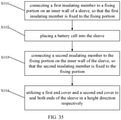
- A method for producing a battery provided in the present application includes the following steps:
- connecting a first insulating member to a fixing portion on an inner wall of a sleeve, so that the first insulating member is fixed to the fixing portion;
- placing a battery cell into the sleeve;
- connecting a second insulating member to the fixing portion, so that the second insulating member is fixed to the fixing portion; and
- utilizing a first end cover and a second end cover to seal both ends of the sleeve in a height direction respectively.
- The present application helps to reduce space occupation by disposing the fixing portion on the inner wall of the sleeve and fixing the first insulating member and the second insulating member to the fixing portion. Therefore, it is advantageous to improve energy density of the battery.
- The exemplary embodiments of the present application are described in details below by referring to the following accompanying drawings, and other characteristics and their advantages of the present application will become clear.
- To describe the technical solutions in the embodiments of the present application or in the prior art more clearly, the following briefly describes the accompanying drawings required for describing the embodiments or the prior art. Apparently, the accompanying drawings in the following description show merely some of the embodiments of the present application, and a person of ordinary skill in the art may still derive other drawings from these accompanying drawings without creative efforts.
-
FIG. 1 is a structural diagram of an electric apparatus in embodiments of the present application. -
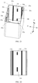
FIG. 2 is a 3D exploded view of a battery in a first embodiment of the present application. -
FIG. 3 is a 3D view of a sleeve inFIG. 2 . -
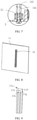
FIG. 4 is a partially enlarged view of I inFIG. 3 . -
FIG. 5 is a side view of a battery inFIG. 2 . -
FIG. 6 is an A-A section view ofFIG. 5 . -
FIG. 7 is a partially enlarged view at II inFIG. 6 . -
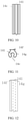
FIG. 8 is a structural diagram of a side wall of a sleeve in a second embodiment of the present application. -
FIG. 9 is a partial 3D view of a convex ridge inFIG. 8 . -
FIG. 10 is a main view ofFIG. 9 . -
FIG. 11 is a vertical view ofFIG. 9 . -
FIG. 12 is a left view ofFIG. 9 . -
FIG. 13 is a 3D exploded view of a battery in a third embodiment of the present application. -
FIG. 14 is a structural diagram of a side wall of a sleeve inFIG. 13 . -
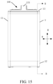
FIG. 15 is a side view of a battery shown inFIG. 13 . -
FIG. 16 is a B-B section view ofFIG. 15 . -
FIG. 17 is a partially enlarged view at III inFIG. 16 . -
FIG. 18 is a partially enlarged view at IV inFIG. 16 . -
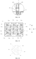
FIG. 19 is a vertical view after a second end cover and a second insulating member are omitted from a battery shown inFIG. 13 . -
FIG. 20 is a partially enlarged view at V inFIG. 19 . -
FIG. 21 is a 3D view of a sleeve in a fourth embodiment of the present application. -
FIG. 22 is a structural diagram of a side wall of a sleeve inFIG. 21 . -
FIG. 23 is a 3D view of a sleeve in a fifth embodiment of the present application. -
FIG. 24 is a structural diagram of a side wall of a sleeve inFIG. 23 . -
FIG. 25 is a 3D exploded view after a first end cover, a second end cover and a battery module are omitted from a battery in a sixth embodiment of the present application. -
FIG. 26 is a side view of an assembling state inFIG. 25 . -
FIG. 27 is a local diagram upon C-C section inFIG. 26 . -
FIG. 28 is a partially enlarged view at VI inFIG. 27 . -
FIG. 29 is a coordinating diagram of a second insulating member and a sleeve in a seventh embodiment of the present application. -
FIG. 30 is a partially enlarged view at VII inFIG. 29 . -
FIG. 31 is a coordinating diagram of a second insulating member and a sleeve in an eighth embodiment of the present application. -
FIG. 32 is a partially enlarged view at VIII inFIG. 31 . -
FIG. 33 is a longitudinal section view of a battery in a ninth embodiment of the present application. -
FIG. 34 is a partially enlarged view at IX inFIG. 33 . and -
FIG. 35 is an assembling method of a battery in embodiments of the present application. - The following clearly and completely describes the technical solutions in the embodiments of the present application with reference to the accompanying drawings in the embodiments of the present application. Apparently, the described embodiments are merely some but not all of the embodiments of the present application. The following description on the at least one exemplary embodiment is actually illustrative only, but not to make any limitation to the present application and its application or use. All other embodiments obtained by a person of ordinary skill in the art based on the embodiments of the present application without creative efforts shall fall within the protection scope of the present application.
- A technique, method and device known for a person of ordinary skill in the art is not likely to be discussed in details. However, at an appropriate situation, the technique, method and device should be regarded as a part of the granted description.
- In the descriptions of the present application, it should be noted that unless otherwise described additionally, "plural" means more than two; and the orientations or positional relationships indicated by the terms "up", "down", "left", "right", "inside", "outside", and the like are merely intended to facilitate the descriptions of the present application and simplify the descriptions, but not intended to indicate or imply that the apparatuses or components mentioned must have specific orientations, or be constructed and operated for a specific orientation, and therefore shall not be understood as a limitation to the present application. In addition, the terms "first", "second" and "third" etc. are merely intended for a purpose of description, and shall not be understood as an indication or implication of relative importance. "Vertical" does not mean vertical in the strict sense, but to be vertical within a permitted range of an error. "Parallel" does not mean parallel in the strict sense, but to be parallel within a permitted range of an error.
- The location words appearing in the following descriptions are all directions indicated in the drawings, but not to constitute any limitation to the specific structure of the present application. In the description of the present application, it should be further noted that unless otherwise prescribed and defined clearly, terms "mounting", "communicating" and "connection" should be understood in a broad sense, which for example can be a fixed connection and can also be a detachable connection or an integral connection; or can be a direct connection and can also be a connection through an intermediary. A person of ordinary skill in the art can understand specific meanings of these terms in the present application based on specific situations.
- In addition, the technical features involved in different implementation manners of the present application as described below can be combined to each other as long as they do not constitute conflicts to each other.
- Energy density is a vital property indicator of a battery for indicating energy released by an average unit volume or mass of the battery. The bigger the energy density, the better the performance of the battery.
- In related arts, energy density is mostly improved by changing a structure of a battery cell in the batter and the like.
- However, in the process of putting the present application into practice, the inventor found that the fixing manner of insulating members located at upper and lower sides of a battery cell in the battery also has some effects on energy density.
- Based on the above discovery, improvement is made by embodiments of the present application to the structure of the battery, aiming to improve energy density of the battery.
-
FIG. 1 to FIG. 35 illustratively show anelectric apparatus 10, a structure of abattery 100 and a method for producing abattery 100 in embodiments of the present application. - In order to describe each location clearly below, firstly a coordinate system in
FIG. 2 is used to define each direction of thebattery 100, where coordinate axis H denotes a height direction of thebattery 100, which is also a height direction of abox body 1 and abattery module 2 in thebox body 1 simultaneously, known as a first direction H; coordinate axis L is perpendicular to coordinate axis H and denotes a length direction of thebattery 100, which is also a length direction of thebox body 1 and thebattery module 2 in thebox body 1 simultaneously, known as a second direction L; and coordinate axis W is perpendicular to coordinate axis H and coordinate axis L, and denotes a width direction of thebattery 100, which is also a width direction of thebox body 1 and thebattery module 2 in thebox body 1, known as a third direction W. - Based on the locations defined above, the nouns indicating orientations or positional relationship like "up", "down, "top" and "bottom" etc. adopted in the following descriptions are all used relative to the first direction H, where the
second end cover 13 and thefirst end cover 12 of thebattery 100 are arranged oppositely along the first direction H, thesecond end cover 13 is up relative to the direction of thefirst end cover 12, and thefirst end cover 12 is down relative to the direction of thesecond end cover 13. - However, it should be understood that the locations defined above are merely intended to facilitate the descriptions of the present application and simplify the descriptions, but not intended to indicate or imply that the apparatuses or components mentioned must have specific orientations, or be constructed and operated for a specific orientation, and therefore shall not be understood as a limitation to the present application when opposite instructions are not made.
- Embodiments of the present application provide an electric apparatus using a battery as a power supply, where the electric apparatus can be a vehicle, a ship, a small aircraft, and other mobile devices, and the electric apparatus includes a power source for providing a driving force to the electric apparatus and the power source can be configured as the battery module for providing electrical energy to the electric apparatus. The driving force of the electric apparatus can all be electrical energy and can also include electrical energy and other energy (for example mechanic energy). The power source can be a battery. In addition, the electric apparatus can also be a battery cabinet and other energy storage devices. The battery cabinet can include a plurality of batteries such that the battery cabinet is capable of outputting electrical energy. Therefore, an electric apparatus shall be within the protection scope of the present application as long as the apparatus is capable of using a battery as a power supply
- Referring to
FIG. 1 , with a vehicle as an example, theelectric apparatus 10 in embodiments of the present application can be a new energy vehicle, which can be a pure electric vehicle or a hybrid power vehicle or an extended-range vehicle etc., and an electric three-wheeled vehicle or a two-wheeled electric vehicle, comprising anapparatus body 200 and abattery 100. Thebattery 100 is disposed in theapparatus body 200 for providing electrical energy. - Next, the structure and the production method of the
battery 100 are mainly introduced in embodiments of the present application by combiningFIG. 2 to FIG. 35 . - Referring to
FIG. 2 to FIG. 34 , in some embodiments, thebattery 100 includes abox body 1, abattery module 2, a first insulatingmember 3 and a second insulatingmember 4. - The
box body 1 is configured for accommodating thebattery module 2, the first insulatingmember 3, the second insulatingmember 4 and other structural components of thebattery 100, thereby providing protection for thebattery module 2, the first insulatingmember 3, the second insulatingmember 4 and other structural components of thebattery 100. - Referring to
FIG. 2 andFIG. 13 , in some embodiments, thebox body 1 includes asleeve 11, afirst end cover 12 and asecond end cover 13. Thesleeve 11 is for example an aluminum case, the interior of which is provided with acavity 111, and afirst end 11a and asecond end 11b of thecavity 11 which are provided relatively along the first direction H are both open. Thefirst end cover 12 and thesecond end cover 13 are respectively sealing thefirst end 11a and thesecond end 11b of thecavity 111 respectively, so that thefirst end 11a and thesecond end 11b of thesleeve 11 are enclosed thus an enclosed space is formed inside thebox body 11 to accommodate thebattery module 2 and so on. The sealing here means to cover or enclose completely or partially. - Upon application to a two-wheeled electric vehicle and other
electric apparatus 10, generally thefirst end cover 12 is facedown, and thesecond end cover 13 is faceup, that is, thefirst end cover 12 is a bottom cover and thesecond end cover 13 is a top cover. In use, the maintenance or replacement of thebattery module 2, the first insulatingmember 3, the second insulatingmember 4 and other structural components located inside thebox body 1 can be achieved through opening and closing thefirst end cover 12 and thesecond end cover 13. - The shape of the
box body 1 can be various. For example, referring toFIG. 2 andFIG. 5 , in some embodiments, thebox body 1 is in a shape of a cube as a whole. Thesleeve 11 is in a hollow cubic shape with two ends open, and includes four side plates with end to end in order. The four side plates enclose to form thecavity 111 and each two adjacent side plates are perpendicular to each other. The height direction of thesleeve 11 is the first direction H. The shape of thefirst end cover 12 matches the shape of the port of thefirst end 11a of thesleeve 11. The shape of the second end cover 13 matches the shape of the port of thesecond end 11b of thesleeve 12. - Moreover, referring to
FIG. 2 , in some embodiments, thesecond end cover 13 is provided with ahandle 131 thereon for grip while closing and opening thesecond end cover 13 to facilitate the closing and opening of thesecond end cover 13. - The
battery module 2 is accommodated in thecavity 111 as a core structural component of thebattery 100 for powering theelectric apparatus 10. Thebattery module 2 includes at least onebattery cell 21. For example, referring toFIG. 2 , in some embodiments, thebattery module 2 includes a plurality ofbattery cells 21, which are arranged in a matrix. Thebattery cell 21 is for example in a shape of cube or cylinder or the like. InFIG. 2 , thebattery cells 21 are in a cylinder shape specifically and disposed misaligned. Moreover, the axial direction of thebattery cell 21 is along the first direction H. At this time, two ends of thebattery cell 21 provided with electrode terminals are respectively oriented toward thefirst end cover 12 and thesecond end cover 13. - At least part of the first insulating
member 3 is located between thebattery module 2 and thefirst end cover 12. At least part of the second insulatingmember 4 is located between thebattery module 2 and thesecond end cover 13. - The first insulating
member 3 and the second insulatingmember 4 are for example constructed as a harness plate and are furtherly configured to fix a harness of thebattery 100 so as to enable the harness to be more compact and well-organized. - Referring to
FIG. 2 andFIG. 6 , in some embodiments, the first insulatingmember 3 includes anaccommodating groove 32 which is in one-to-one match to thebattery cell 21 and configured for insertion of thebattery cell 21 towards one end of thefirst end cover 12 so as to limit the displacement of thebattery cell 21. Meanwhile, the second insulatingmember 4 further includes anaccommodating groove 32 which is in one-to-one match to thebattery cell 21 and configured for insertion of thebattery cell 21 towards one end of thesecond end cover 13 so as to limit the displacement of thebattery cell 21. - In embodiments of the present application, the first insulating
member 3 and the second insulatingmember 4 are both connected to thesleeve 11. - In order to achieve the connection of the first insulating
member 3 to thesleeve 11, referring toFIG. 2 to FIG. 34 , in some embodiments, an inner wall of thesleeve 11 is provided with a fixingportion 14, and the first insulatingmember 3 and the second insulatingmember 4 are both fixedly connected to the fixingportion 14, that is, the fixingportion 14 is configured to fix the first insulatingmember 3 and the second insulatingmember 4. In this way, the first insulatingmember 3 and the second insulatingmember 4 can be fixed by providing the fixingportion 14 on the inner wall of thesleeve 11 without any other effort. Since other components other than thesleeve 11 are not required, for example, additional fixing portions provided on thefirst end cover 12 for respectively fixing the first insulatingmember 3 and the second insulatingmember 4, which thus helps to save space, for example, space along a height direction of thesleeve 11 and to improve energy density of thebattery 100. - In addition, the connection of the first insulating
member 3 to the inner wall of thesleeve 11 is advantageous to improve strength of thebattery 100. Specifically, when thesleeve 11 is at impact, the connection between the first insulatingmember 3 and the fixingportion 14 on the inner wall of thesleeve 11 can thus reduce the relative displacement between the first insulatingmember 3 and thesleeve 11, thus changing the connecting strength and stability of the first insulatingmember 3 and thebox body 1 and avoiding safety problem due to failed insulation caused by loose connection or even damage brought about by presence of the relative displacement of the first insulatingmember 3 against thesleeve 11. If the first insulating member is not fixed solidly, it will even affect the fixing of other components (for example thebattery cell 21, the bus-bars connecting the battery cell 21 (not shown in the drawings) and a harness (not shown in the drawings) etc.) inside thebattery 100, thus causing safety problem. - Referring to
FIG. 2 to FIG. 24 , in some embodiments, the fixingportion 14 includes aconvex ridge 14c. Theconvex ridge 14c protrudes from the inner wall of thesleeve 11 toward one side of thebattery module 2. The establishment of theconvex ridge 14c not only facilitates implementation of the connection of the first insulatingmember 3 and the second insulatingmember 4 to thesleeve 11, but also performs a function of a reinforcing rib, which is advantageous to enhance overall strength of thebattery 100. - Moreover, referring to
FIG. 8 to FIG. 12 , in some embodiments, a side surface of theconvex ridge 14c is provided with anopening 14e. The side surface of theconvex ridge 14c is a surface of theconvex ridge 14c protruding toward thebattery module 2 and also a surface of theconvex ridge 14c connecting an upper surface and a lower surface of theconvex ridge 14c. The advantages of such setting lie in capability of reducing the risk of shrink marks caused by an excessively thickness of local material when theconvex ridge 14c is processed on the inner wall of thesleeve 11, which is advantageous to enhance strength of thesleeve 11, thus enhancing connecting reliability between theconvex ridge 14c and thesleeve 11. Meanwhile, appearance of thesleeve 11 can also be improved. - Locating the
opening 14e at any ide of the side surface of theconvex ridge 14c can perform a certain function in preventing shrink marks. When it is located at one side of the side surface of theconvex ridge 14c close to thebattery module 2, it is able to ensure structural stability and processability of theconvex ridge 14c on one hand. On the other hand, it is also more advantageous for theconvex ridge 14c to avoid thebattery module 2, thereby further reducing space occupation and improving energy density of thebattery 100. - However, the structure of the fixing
portion 14 is not limited to the above solution. For example, referring toFIG. 25 to FIG. 30 , in some embodiments, the fixingportion 14 includes agroove 14d. Thegroove 14d recesses from the inner wall of thesleeve 11 toward one side of an outer wall. - No matter which structural form the fixing
portion 14 is constructed into, there are multiple manners of connecting the fixingportion 14 with the first insulatingmember 3 and the second insulatingmember 4, such as connecting through abolt 51, a pin (not shown in the drawings) or a screw (not shown in the drawing) or other fastener 5 (FIG. 2 to FIG. 28 andFIG. 33 to FIG. 34 ), or connecting through clamping (FIG. 29 to FIG. 32 ). - In addition, the fixing
portion 14 can be an integral structure. For example, referring toFIG. 2 to FIG. 20 andFIG. 33 to FIG. 34 , in some embodiments, the fixingportion 14 includes an integralconvex ridge 14c that extends along the first direction H; or the fixingportion 14 can also be a split-type structure that includes afirst fixing portion 14a and asecond fixing portion 14b that are disposed separately in the first direction H, where thefirst fixing portion 14a is connected to the first insulatingmember 3, and thesecond fixing portion 14b is connected to the second insulatingmember 4. For example, referring toFIG. 21 to FIG. 24 , in some embodiments, the fixingportion 14 includes two sections of theconvex ridge 14c that are disconnected from each other, and the two selection of theconvex ridge 14c extend along the first direction H. At this time, thefirst fixing portion 14a and thesecond fixing portion 14b are both theconvex ridge 14c. For example again, referring toFIG. 25 to FIG. 32 , in another some embodiments, the fixingportion 14 includes two sections of thegroove 14d that are disconnected from each other, and the two sections of thegroove 14d extend along the first direction H. At this time, thefirst fixing portion 14a and thesecond fixing portion 14b are both thegroove 14d. - When the fixing
portion 14 is a split-type structure, referring toFIG. 21 to FIG. 22 andFig. 25 , in some embodiments, thefirst fixing portion 14a and thesecond fixing portion 14b are disposed just opposite to each other in a direction perpendicular to the first direction H. Referring toFIG. 23 to FIG. 24 , in another some embodiments, thefirst fixing portion 14a and thesecond fixing portion 14b are misaligned to be disposed in a direction perpendicular to the first direction H. - Each of embodiments shown in
FIG. 2 to FIG. 34 will be further described respectively next. - Firstly, the first embodiment shown in
FIG. 2 to FIG. 7 is introduced. - As shown in
FIG. 2 to FIG. 7 , in the embodiment, the fixingportion 14 disposed on the inner wall of thesleeve 11 includes aconvex ridge 14c, which is constructed as a whole piece of a rib that extends along the first direction H and connected to the first insulatingmember 3 and the second insulatingmember 4 through abolt 51. - Specifically, as shown in
FIG. 2 to FIG. 7 , a cross section of theconvex ridge 14c is in a rectangle shape and theconvex ridge 14c is provided with a first mountinghole 141, and the first insulatingmember 3 and the second insulatingmember 4 are respectively provided with a first connectinghole 31 and a second connectinghole 41 correspondingly. Thefirst mounting hole 141 passes through theconvex ridge 14c along the first direction H. Upon assembling, thebolt 51 is made to pass through the first connectinghole 31 and the first mountinghole 141, in which case a fixed connection of the first insulatingmember 3 to theconvex ridge 14c can be implemented; and thebolt 51 is made to pass through the second connectinghole 41 and the first mountinghole 141, in which case a fixed connection of the second insulatingmember 4 to theconvex ridge 14c can be implemented. In this case, the structure is simple and the assembling is easy. - Ur The number of the
convex ridge 14c is not limited to one. For example, four side walls of thesleeve 11 can all be provided with theconvex ridges 14c respectively. On such a basis, the circumferences of the first insulatingmember 3 and the second insulatingmember 4 can be connected to thesleeve 11 through the correspondingconvex ridge 14c, resulting in solid connection and improved stability. - Meanwhile, as shown in
FIG. 3 andFIG. 6 , in the embodiment, an interval exists between the convex ridge 14cand thefirst end 11a and thesecond end 11b of thesleeve 11, that is, in the first direction H, theconvex ridge 14c is not aligned with thefirst end 11a and thesecond end 11b of thesleeve 11, but to be located between thefirst end 11a and thesecond end 11b. In this way, the first insulatingmember 3 and the second insulatingmember 4 are both at least partially located in thesleeve 11, which makes the overall structure of thebattery 100 more compact and solid. Moreover, a circuit board (not shown in the drawings), a harness (not shown in the drawings) and other components may be placed between the second insulatingmember 4 and thesecond end cover 13. Thus, an interval exists between theconvex ridge 14c, will facilitate the accommodating of the circuit board, the harness and other components into thefirst end 11a and thesecond end 11b of thesleeve 11, which is advantageous for keeping those components from risk when thebattery 100 is at impact. - As a variant, in other embodiments, the
convex ridge 14c can also have an interval only between one of thefirst end 11a and thesecond end 11b but being aligned with the other of thefirst end 11a and thesecond end 11b; that is, the fixingportion 14 can have an interval with at least one end of the two ends of thesleeve 11 in the height direction, or, two ends of theconvex ridge 14c can also be aligned with thefirst end 11a and thesecond end 11b of thesleeve 11 respectively. - Next, the second embodiment shown in
FIG. 8 to FIG. 12 is introduced. - In order to simplify descriptions, only differences of the second embodiment from the first embodiment are mainly described herein.
- As shown in
FIG. 8 to FIG. 12 , in the embodiment, one end of theconvex ridge 14c close to thebattery module 2 is provided with anopening 14e, that is, theopening 14e is located at one side of a side surface of theconvex ridge 14c close to thebattery module 2 to prevent generation of shrink marks, enhance strength, avoid thebattery cell 21 and improve energy density. - Meanwhile, as shown in
FIG. 9 to FIG. 12 , in the embodiment, theconvex ridge 14c includes a firstconvex ridge portion 14f and a secondconvex ridge portion 14g, the firstconvex ridge portion 14f connects the secondconvex ridge portion 14g to an inner wall of thesleeve 11 and a cross section of theconvex ridge 14c becomes narrower at a connecting place of the firstconvex ridge portion 14f and the secondconvex ridge portion 14g, that is, the connecting place of the firstconvex ridge portion 14f and the secondconvex ridge portion 14g is narrower relative to other portions of theconvex ridge 14c. Such setting has advantageous of helping to reduce the material usage of theconvex ridge 14c, make the wall thickness of theconvex ridge 14c even, and reduce the risk of shrink marks appearing to thesleeve 11 due to excessive thickness of theconvex ridge 14c, thus helping to improve connecting strength of theconvex ridge 14c with the first insulatingmember 3 and the second insulatingmember 4 as well as the strength of thesleeve 11 itself. - In the embodiment, the
first end cover 12 and thesecond end cover 13 can be detachably connected to thesleeve 11. On such a basis, as compared with a case in which thefirst end cover 12 and thesleeve 11 are formed as an integral structure, since thefirst end cover 12 can be connected again to thesleeve 11 after the first insulatingmember 3 is connected to thesleeve 11, thus it is more convenient for connection of the first insulatingmember 3 to thesleeve 11, which not only helps to reduce assembly difficulty of thebattery 100 and improve assembly efficiency of thebattery 100, but also helps to reduce the space reserved between thebattery module 2 and thebox body 1 for mounting the first insulatingmember 3, thus further improving energy density of thebattery 100. - In assembling the
battery 100, for example, firstly thefastener 5 is used to lock-attach the first insulatingmember 3 to theconvex ridge 14c from a lower side, thus realizing a detachable connection of the first insulatingmember 3 to thesleeve 11. Then, thebattery module 2 is placed into thesleeve 11 and thefastener 5 is used to lock-attach the second insulatingmember 4 to theconvex ridge 14c, thus establishing a detachable connection of the second insulatingmember 4 to thesleeve 11. Then, thefirst end cover 12 and thesecond end cover 13 are connected onto thesleeve 11 to complete assembling of thebattery 100. In the process, it is not necessary to dip tools into thebox body 1 for operation, ensuring its simplicity and processability. Moreover, it is not necessary to set more operation space between thebattery module 2 and thebox body 1 for mounting the first insulatingmember 3, thus implementing high space occupation rate and high energy density of thebattery 100. - Next, the third embodiment shown in
FIG. 13 to FIG. 20 is introduced. - As shown in
FIG. 13 and FIG. 14 , in the embodiment, the inner wall of thesleeve 11 is not only provided with theconvex ridge 14c used as the fixingportion 14, but also simultaneously provided with a connectingportion 15, which connects thefirst end cover 12 to thesecond end cover 13, and specifically includes a connectingrib 15a, which protrudes from one side of the inner wall of thesleeve 11 toward thebattery module 2. - The disposed connecting
rib 15a helps to further improve strength of thebattery 100. Moreover, since the connectingrib 15a is located inside thesleeve 11, thus it also helps to reduce space occupation and improve energy density relative to a situation in which a connecting part of thefirst end cover 12 and thesecond end cover 13 with thesleeve 11 is located outside thesleeve 11. Meanwhile, establishing the connectingrib 15a to connect thesleeve 11 to thefirst end cover 12 and thesecond end cover 13 also facilitates implementation of a detachable connection between thefirst end cover 12 and thesecond end cover 13, and thesleeve 11, thus helping to further reduce assembling difficulty of thebattery 100 and increase energy density of thebattery 100. - Specifically, as shown in
FIG. 13 andFIGs. 16-17 , in the embodiment, thefirst end cover 12 and thesecond end cover 13 are both connected to the connectingrib 15a through a connectingpiece 6. More specifically, as shown inFIG. 14 andFIG. 17 , the connectingrib 15a is provided with asecond mounting hole 151, and thefirst end cover 12 and thesecond end cover 13 are both provided with a coordinatinghole 121 corresponding to thesecond mounting hole 151. Thesecond mounting hole 151 for example passes through the connectingrib 15a along the first direction H.The connecting piece 6 is for example abolt 51, a pin (not shown in the drawing) or a screw (not shown in the drawings), and it is for example further coated with a thread locker (not shown in the drawings) to perform the function of increasing connecting strength and sealing etc. In this way, the connectingpiece 6 passes through the coordinatinghole 121 on thefirst end cover 12 and thesecond mounting hole 151, thus realizing a convenient detachable connection of thefirst end cover 12 to thesleeve 11. The connectingpiece 6 passes through the coordinatinghole 121 and thesecond mounting hole 151 on thesecond end cover 13, thus realizing detachable connection of thesecond end cover 13 to thesleeve 11 conveniently. - Since one same connecting
rib 15a is used, detectable connection of thefirst end cover 12 and thesecond end cover 13 to thesleeve 11 can be implemented conveniently. Thus, the structure is simple and the connection is convenient. - As shown in
FIG. 14 , in the embodiment, the connectingrib 15a is similar with theconvex ridge 14c in structure. For example, both are provided with anopening 14e. For example again, the cross section becomes narrower at a connecting place of the firstconvex ridge portion 14f and the secondconvex ridge portion 14g. - Meanwhile, as shown in
FIG. 14 , the connectingrib 15a also differs from theconvex ridge 14c in some points. For example, the connectingrib 15a does not have an interval between two ends of thesleeve 11 in the height direction, as the connectingrib 15a is roughly aligned with two ends of thesleeve 11 in the height direction, that is, the connectingrib 15a roughly extends from thefirst end 11a of thesleeve 11 to thesecond end 11b. On such a basis, theconvex ridge 14c and the connectingrib 15a differ from each other in height. According to the height of theconvex ridge 14c and the connectingrib 15a, they can be distinguished conveniently, thus rapidly determining the orientations to place the first insulatingmember 3, the second insulatingmember 4, thefirst end cover 12 and thesecond end cover 13 in the process of assembling thebattery 100, so as to improve assembling efficiency. Meanwhile, the height difference of theconvex ridge 14c and the connectingrib 15a are more adapted to the fixing requirements of the insulating member and end cover at different heights, thus helping to implement a higher assembly efficiency ofbattery 100. - It can be seen that ribs of different heights are disposed on the
sleeve 11 for connecting and fixing the insulating member and the end cover respectively, which helps to not only effectively increase energy density of thebattery 100, but also improve assembling efficiency ofbattery 100. - As shown in
FIG. 19 , in the embodiment, four side walls of surfaces of thesleeve 11 are all provided with theconvex ridge 14c and the connectingrib 15a simultaneously, such that the circumferences of the first insulatingmember 3 and the second insulatingmember 4 are both connected to thesleeve 11, ensuring an even stress distribution of the first insulatingmember 3 and the second insulatingmember 4. Moreover, the circumferences of thefirst end cover 12 and thesecond end cover 13 are both connected to thesleeve 11 as well, improving the sealing effects of thebattery 100 thus makes the overall structure of thebattery 100 also more solid and stable. - Arranging the
convex ridge 14c and the connectingrib 15a on the inner wall of thesleeve 11 is convenient to avoid thebattery cell 21. - In order to further reduce space occupation, as shown in
FIG. 19 and FIG. 20 , in the embodiment, on a direction perpendicular to the first direction H, some of theconvex ridge 14c and the connectingrib 15a are located between twoadjacent battery cells 21 of thebattery module 2, that is, along the second direction L or the third direction W, theconvex ridge 14c and the connectingrib 15a protrude toward a point between the adjacent twobattery cells 21. In this way, theconvex ridge 14c and the connectingrib 15a do not need additionally space in the second direction L or the third direction W. Therefore, internal space of thebattery 100 can be further improved and the energy density of thebattery 100 is thus further improved. - In addition, referring to
FIG. 19 , in the embodiment, the second insulatingmember 4 is further abutted against by thesecond end cover 13. Since in this case thesecond end cover 13 is capable of further limiting displacement of the second insulatingmember 4, it further helps to improve the stability of the overall structure ofbattery 100. - Moreover, as shown in
FIG. 13 ,FIG. 16 andFIG. 18 , in the embodiment, a buffer 7 made in foam or other materials is further provided between the abutting parts of the second insulatingmember 4 and thesecond end cover 13, that is, the second insulatingmember 4 is provided with a buffer 7 and thesecond end cover 13 abuts against the buffer 7. The advantages of setting the buffer 7 lie in capability of the buffer 7 for making up a size tolerance of the second insulatingmember 4 and thesecond end cover 13 on one hand so as to improve the abutting effect between the second insulatingmember 4 and thesecond end cover 13, and on the other hand, the buffer 7 enables no requirement of direct rigid contact between the second insulatingmember 4 and thesecond end cover 13, thus helping to reduce abrasion between the second insulatingmember 4 and thesecond end cover 13. - Specifically, as shown in
FIG. 13 ,FIG. 16 andFIG. 18 , in the embodiment, a surface of thesecond end cover 13 toward the second insulatingmember 4 is provided with afirst boss 132, which protrudes toward the second insulatingmember 4. Meanwhile, a surface of one side of the second insulatingmember 4 facing toward thesecond end cover 13 is correspondingly provided with asecond boss 42, which protrudes toward thesecond end cover 13. After the assembly is completed, thefirst boss 132 abuts against thesecond boss 42, that is, an abutting part of thesecond end cover 13 and the second insulatingmember 4 is located at thefirst boss 132 and thesecond boss 42. At this time, the buffer 7 can be disposed between thefirst boss 132 and thesecond boss 42, that is, the buffer 7 is disposed on thesecond boss 42 and thefirst boss 132 abuts against the buffer 7. - Although not shown, it can be understood that in other embodiments, a buffer 7 can also be provided between the first insulating
member 3 and thefirst end cover 12 to improve an abutting effect between the first insulatingmember 3 and thefirst end cover 12, and reduce abrasion between the first insulatingmember 3 and thefirst end cover 12. - Next, two embodiments shown in
FIG. 21 to FIG.FIG. 22 andFIG. 23 to FIG. 24 are introduced. - As shown in
FIG. 21 to FIG. 24 , the two embodiments are variants of the embodiment shown inFIG. 13 to FIG. 20 , and they mainly differ from the embodiment shown inFIG. 13 to FIG. 20 in that the fixingportion 14 is no longer an integral structure, but to be constructed as a split structure. - As shown in
FIG. 22 to FIG. 24 , in the two embodiments, the fixingportion 14 includes afirst fixing portion 14a and asecond fixing portion 14b that are disconnected from each other in the first direction H, and thefirst fixing portion 14a and thesecond fixing portion 14b are specifically constructed as a convex ridge. In other words, although the fixingportion 14 in the two embodiments is still theconvex ridge 14c, it is not a continuous structure, but to be split into two sections of the disconnected convex ridge. In this way, the weight of the entire battery can be reduced and the energy density of the battery can be improved. - The difference lies, in the embodiment shown in
FIG. 21 to FIG. 22 , thefirst fixing portion 14a and thesecond fixing portion 14b are disposed just opposite to each other in a direction perpendicular to the first direction H, that is, thefirst fixing portion 14a and thesecond fixing portion 14b are disposed opposite to each other in the length direction L or the width direction W of thesleeve 11; but in the embodiment shown inFIG. 23 to FIG. 24 , thefirst fixing portion 14a and thesecond fixing portion 14b are misaligned to be disposed in a direction perpendicular to the first direction H, that is, thefirst fixing portion 14a and thesecond fixing portion 14b are misaligned to be disposed in the length direction L or the width direction W of thesleeve 11. Establishing in a misaligned manner can provide a better reinforcing effect for thesleeve 11 while improving energy density. - In the previous embodiments, the fixing
portion 14 is constructed as aconvex ridge 14c. However, as described above, the fixingportion 14 can actually be constructed as agroove 14d and other structural forms as well. Next, the embodiments shown inFIG. 25 to FIG. 28 will be explained. - As shown in
FIG. 25 to FIG. 28 , in the embodiment, the fixingportion 14 includes agroove 14d, which recesses from the inner wall of thesleeve 11 to one side of an outer wall. Moreover, specifically, thegroove 14d is still connected to the first insulatingmember 3 and the second insulatingmember 4 through afastener 5 such as abolt 51. - More specifically, the fixing
portion 14 includes twogrooves 14d that are disposed separately in the first direction H. An inner wall between the twogrooves 14d is provided with a fixinghole 14g matching both a first connectinghole 31 on the first insulatingmember 3 and a second connectinghole 41 on the second insulatingmember 4, and thebolt 51 connects with the first connectinghole 31 or the second connectinghole 41 by passing through the fixinghole 14g, such that the connection of the first insulatingmember 3 or the second insulatingmember 4 to the fixingportion 14 can be implemented. - In some embodiments, of the embodiments described above, the first insulating
member 3 and the second insulatingmember 4 are connected to the fixingportion 14 through thefastener 5. Next, by combiningFIG. 26 to FIG. 29 , the method of clamping the first insulatingmember 3 and the second insulating member 4with the fixingportion 14 is described. - In the embodiments shown in
FIG. 29 to FIG. 30 , the fixingportion 14 includes agroove 14d and the first insulatingmember 3 and the second insulatingmember 4 are provided with ahook 14h, which is clamped to thegroove 14d, such that clamping the first insulatingmember 3 and the second insulatingmember 4 with the fixingportion 14 can be achievable. - In the embodiments shown in
FIG. 31 to FIG. 32 , the positions for disposing thegroove 14d and thehook 14h are exchangeable, that is, the fixingportion 14 includes ahook 14h and the first insulatingmember 3, and the second insulatingmember 4 are provided with agroove 14h which is clamped to thegroove 14d, in which case clamping between the first insulatingmember 3 and the second insulating member 4with the fixingportion 14 can also be achievable. - In addition, in each embodiment shown in
FIG. 2 to FIG. 28 , the fixingportion 14 is not simultaneously connected to thefirst end cover 12 and thesecond end cover 13, thefirst end cover 12 and thesecond end cover 13 are connected to thesleeve 11 through the connectingportion 15 and other structures other than the fixingportion 14. However, actually, thefirst end cover 12 and thesecond cover 13 can also be connected onto the fixingportion 14. For example, in the embodiment shown inFIG. 33 to FIG. 34 , thefirst end cover 12, thesecond end cover 13, the first insulatingmember 3 and the second insulatingmember 4 are all connected to theconvex ridge 14c which is used as the fixingportion 14, that is, the fixingportion 14 not only is used to fix the first insulatingmember 3 and the second insulatingmember 4, but also is used to fix thefirst end cover 12 and thesecond end cover 13. At this time, it is not necessary to additionally establish more connectingportion 15 other than the fixingportion 14, in which case the connection of thefirst end cover 12 and thesecond end cover 13 with thesleeve 11 can be implemented, thus reducing the number of components, improving energy density and reducing cost. - Referring to
FIG. 35 , embodiments of the present application further provide a method for producing a battery (100), comprising following steps: - S101: connecting a first insulating
member 3 to a fixingportion 14 on an inner wall of asleeve 11, so that the first insulatingmember 3 is fixed to the fixingportion 14; - S102: placing a
battery cell 21 into thesleeve 11; - S103: connecting a second insulating
member 4 to the fixingportion 14, so that the second insulatingmember 4 is fixed to the fixingportion 14; and - S104: utilizing a
first end cover 12 and asecond end cover 13 to seal both ends of thesleeve 11 in a height direction respectively. - The above steps can be adjustable. For example, in some embodiment, the step S102 can also be implemented prior to the step 101; or the sequence of the step S103 and the step S101 can be exchanged.
- With the production method in embodiments of the present application, the first insulating
member 3 and the second insulatingmember 4 do not require assembling of eachbattery cell 21 together or then its assembling as a whole to thebox body 1, as the first insulatingmember 3 or the second insulatingmember 4 is firstly fixed onto thesleeve 11, and then each battery cell 21is assembled, or eachbattery cell 21 is firstly assembled and then the first insulatingmember 3 or the second insulatingmember 4 is fixed onto thesleeve 11, in which case, the insulating member and thebattery module 2 are respectively assembled onto thebox body 1, so that the assembling is more convenient and efficient. - Meanwhile, based on the production method in the embodiments of the present application, it is also convenient to maintain the
battery 100. After the insulating member and thebattery module 2 are assembled as a whole, and then placed into thebox body 1, when maintain thebattery cell 21, it is necessary to dismount the first insulatingmember 3, thebattery module 2 and the second insulatingmember 4 from thebox body 1 in sequence, which may involve troubles. However, in the embodiments of the present application, the maintenance of thebattery module 2 can be implemented as it is only necessary to dismount one of the first insulatingmember 3 and the second insulatingmember 4 with thebattery module 2, which is simpler and more efficient. - The foregoing descriptions are merely exemplary embodiments of the present application, but are not intended to limit the present application. Any modification, equivalent replacement, or improvement or parameters made without departing from the spirit and principle of the present application shall fall within the protection scope of the present application.
Claims (12)
- A battery (100), comprising:a battery cell (21);a box body (1), configured to accommodate the battery cell (21) and comprising a sleeve (11) and a first end cover (12) and a second end cover (13) for sealing both ends of the sleeve (11) in a height direction respectively;a first insulating member (3), at least part of the first insulating member (3) being located between the first end cover (12) and the battery cell (21); anda second insulating member (4), at least part of the second insulating member (4) being located between the second end cover (13) and the battery cell (21);wherein an inner wall of the sleeve (11) is provided with a fixing portion (14), and the fixing portion (14) is configured to fix the first insulating member (3) and the second insulating member (4).
- The battery (100) according to claim 1, wherein the fixing portion (14) comprises a convex ridge (14c) and/or a groove (14d).
- The battery (100) according to claim 2, wherein a side surface of the convex ridge (14c) is provided with an opening (14e).
- The battery (100) according to claim 3, wherein the opening (14e) is located at a side of the convex ridge (14c) close to the battery cell (21).
- The battery (100) according to any one of claims 1-4, wherein an interval exists between the fixing portion (14) and at least one of both ends of the sleeve (11) in a height direction, so that the first insulating member (3) and/or the second insulating member (4) are accommodated in the sleeve (11).
- The battery (100) according to any one of claims 1-5, wherein the fixing portion (14) is connected to the first insulating member (3) and the second insulating member (4) through a fastener (5); or, the fixing portion (14) is clamped to the first insulating member (3) and the second insulating member (4).
- The battery (100) according to claim 6, wherein the fastener (5) comprises a bolt (51); or, the first insulating member (3) and the second insulating member (4) are provided with a hook (14h), and the hook (14h) is configured to clamp the groove (14d) of the fixing portion (14).
- The battery (100) according to any one of claims 1-7, wherein the fixing portion (14) comprises a first fixing portion (14a) and a second fixing portion (14b) separately arranged in a height direction of the sleeve (11), and the first fixing portion (14a) is configured to fix the first insulating member (3), and the second fixing portion (14b) is configured to fix the second insulating member (4).
- The battery (100) according to claim 8, wherein the first fixing portion (14a) and the second fixing portion (14b) are misaligned to be disposed in a length direction or width direction of the sleeve (11).
- The battery (100) according to any one of claims 1-9, wherein the fixing portion (14) is further configured to fix the first end cover (12) and the second end cover (13).
- An electric apparatus (10), comprising the battery (100) as claimed in any one of claims 1-10, wherein the battery (100) is configured to provide electrical energy.
- A method for producing a battery (100), comprising following steps:connecting a first insulating member (3) to a fixing portion (14) on an inner wall of a sleeve (11), so that the first insulating member (3) is fixed to the fixing portion (14);placing a battery cell (21) into the sleeve (11);connecting a second insulating member (4) to the fixing portion (14), so that the second insulating member (4) is fixed to the fixing portion (14); andutilizing a first end cover (12) and a second end cover (13) to seal both ends of the sleeve (11) in a height direction respectively.
Applications Claiming Priority (2)
| Application Number | Priority Date | Filing Date | Title |
|---|---|---|---|
| CN202010274774.9A CN112310547B (en) | 2020-04-09 | 2020-04-09 | Battery, electric device and battery production method |
| PCT/CN2020/139597 WO2021203742A1 (en) | 2020-04-09 | 2020-12-25 | Battery, electric apparatus and method for producing battery |
Publications (4)
| Publication Number | Publication Date |
|---|---|
| EP3958383A1 true EP3958383A1 (en) | 2022-02-23 |
| EP3958383A4 EP3958383A4 (en) | 2022-11-23 |
| EP3958383C0 EP3958383C0 (en) | 2024-02-07 |
| EP3958383B1 EP3958383B1 (en) | 2024-02-07 |
Family
ID=74336480
Family Applications (1)
| Application Number | Title | Priority Date | Filing Date |
|---|---|---|---|
| EP20929821.5A Active EP3958383B1 (en) | 2020-04-09 | 2020-12-25 | Battery, electric apparatus and method for producing battery |
Country Status (6)
| Country | Link |
|---|---|
| US (1) | US11973236B2 (en) |
| EP (1) | EP3958383B1 (en) |
| JP (1) | JP7341346B2 (en) |
| KR (1) | KR102684449B1 (en) |
| CN (1) | CN112310547B (en) |
| WO (1) | WO2021203742A1 (en) |
Families Citing this family (3)
| Publication number | Priority date | Publication date | Assignee | Title |
|---|---|---|---|---|
| CN114447494B (en) * | 2021-11-25 | 2024-07-26 | 东莞新能安科技有限公司 | Battery pack and power-using device |
| CN114464947B (en) * | 2022-02-10 | 2022-08-23 | 深圳市乔威电源有限公司 | Mobile power supply equipment with adjustable electricity storage capacity |
| US20250300311A1 (en) * | 2024-08-15 | 2025-09-25 | Shenzhen Hello Tech Energy Co., Ltd | Energy storage power supply |
Family Cites Families (20)
| Publication number | Priority date | Publication date | Assignee | Title |
|---|---|---|---|---|
| JP2011049014A (en) * | 2009-08-26 | 2011-03-10 | Sanyo Electric Co Ltd | Battery pack of waterproof structure |
| US20110250488A1 (en) * | 2010-04-12 | 2011-10-13 | Sin-Young Park | Secondary battery |
| CN102214806B (en) * | 2010-04-12 | 2014-08-20 | 三星Sdi株式会社 | Battery module |
| EP2400578B1 (en) | 2010-06-25 | 2013-04-03 | Samsung SDI Co., Ltd. | Secondary Battery |
| JP5807488B2 (en) * | 2011-09-28 | 2015-11-10 | ソニー株式会社 | Battery holder, battery storage case, battery pack, power storage system, electronic device, and electric vehicle |
| US20130143079A1 (en) * | 2011-12-02 | 2013-06-06 | Golden Crown New Energy (Hk) Limited | Battery system with heat-dissipation improvement and connecting circuit arrangement |
| US20140242449A1 (en) * | 2013-02-28 | 2014-08-28 | Samsung Sdi Co., Ltd. | Pack Case for Battery |
| FR3009423B1 (en) * | 2013-07-30 | 2015-08-21 | Blue Solutions | ENERGY STORAGE MODULE COMPRISING A PLURALITY OF ENERGY STORAGE ASSEMBLIES |
| JP6283964B2 (en) * | 2014-02-07 | 2018-02-28 | パナソニックIpマネジメント株式会社 | Battery module |
| JP6680872B2 (en) * | 2016-04-14 | 2020-04-15 | 株式会社オートネットワーク技術研究所 | Power storage device |
| CN205882025U (en) * | 2016-08-09 | 2017-01-11 | 天津力神电池股份有限公司 | Gapless power battery module |
| CN206293510U (en) * | 2016-12-21 | 2017-06-30 | 天津力神特种电源科技股份公司 | A kind of fixed structure of the lithium-ions battery with security maintainability testability |
| KR102162968B1 (en) * | 2017-04-07 | 2020-10-07 | 주식회사 엘지화학 | Battery Pack with extendible battery module |
| CN207038609U (en) * | 2017-08-23 | 2018-02-23 | 江西捷控新能源科技有限公司 | A kind of novel battery module |
| JP7128828B2 (en) | 2017-09-29 | 2022-08-31 | 三洋電機株式会社 | power supply |
| CN207781669U (en) * | 2017-11-29 | 2018-08-28 | 长城汽车股份有限公司 | Battery pack for vehicle and the vehicle with it |
| CN108832049A (en) * | 2018-06-26 | 2018-11-16 | 安徽相源新能源有限公司 | A kind of new-energy automobile lithium battery lithium cell component |
| KR102666368B1 (en) * | 2018-09-11 | 2024-05-17 | 삼성에스디아이 주식회사 | Battery pack |
| CN109664744A (en) * | 2018-12-20 | 2019-04-23 | 天津力神特种电源科技股份公司 | A kind of fixed frame and the automobile-used Li-ion batteries piles structure of AGV of the automobile-used Li-ion batteries piles of AGV |
| CN210272481U (en) * | 2019-09-16 | 2020-04-07 | 苏州超威新能电源科技有限公司 | Battery pack for electric vehicle |
-
2020
- 2020-04-09 CN CN202010274774.9A patent/CN112310547B/en active Active
- 2020-12-25 EP EP20929821.5A patent/EP3958383B1/en active Active
- 2020-12-25 KR KR1020227017273A patent/KR102684449B1/en active Active
- 2020-12-25 WO PCT/CN2020/139597 patent/WO2021203742A1/en not_active Ceased
- 2020-12-25 JP JP2022534437A patent/JP7341346B2/en active Active
-
2021
- 2021-12-30 US US17/565,544 patent/US11973236B2/en active Active
Also Published As
| Publication number | Publication date |
|---|---|
| JP7341346B2 (en) | 2023-09-08 |
| EP3958383A4 (en) | 2022-11-23 |
| KR102684449B1 (en) | 2024-07-11 |
| KR20220086655A (en) | 2022-06-23 |
| US11973236B2 (en) | 2024-04-30 |
| WO2021203742A1 (en) | 2021-10-14 |
| EP3958383C0 (en) | 2024-02-07 |
| US20220123410A1 (en) | 2022-04-21 |
| CN112310547B (en) | 2024-09-03 |
| CN112310547A (en) | 2021-02-02 |
| EP3958383B1 (en) | 2024-02-07 |
| JP2023505970A (en) | 2023-02-14 |
Similar Documents
| Publication | Publication Date | Title |
|---|---|---|
| US11973236B2 (en) | Battery, electric apparatus and method for producing battery | |
| EP4191765A1 (en) | Holder body, holder, battery module, and energy storage power source | |
| WO2023065982A1 (en) | Case, battery and power consuming device | |
| EP4456294A1 (en) | Battery, electric device, and forming method for battery | |
| CN114388958A (en) | Battery case, battery and electrical device | |
| CN217485627U (en) | Batteries and Electrical Devices | |
| CN116666917A (en) | Battery cells, batteries and electrical devices | |
| US20250210791A1 (en) | Battery and electric device | |
| US20240266694A1 (en) | Electrode terminal, pole assembly, battery, and electric device | |
| KR20220161480A (en) | Fixing member, battery, electric device and battery manufacturing method and manufacturing system | |
| CN116706409A (en) | Battery, its manufacturing method and manufacturing system, and electrical device | |
| CN221486683U (en) | Batteries and electrical devices | |
| CN223871495U (en) | Battery devices and electrical equipment | |
| CN223539804U (en) | Battery pack and electricity utilization device | |
| CN223625181U (en) | Single battery, battery and electric equipment | |
| CN223206412U (en) | Battery pack and electricity utilization device | |
| CN221805779U (en) | Battery cell, battery and electricity utilization device | |
| CN222483580U (en) | Battery box, battery and electrical device | |
| CN219498007U (en) | Battery pack | |
| CN224020959U (en) | Battery devices and electrical equipment | |
| WO2025102818A1 (en) | Battery case body, battery and electrical apparatus | |
| CN222394960U (en) | Battery pack and electrical equipment | |
| CN115360472B (en) | Battery pack and electric device | |
| EP4510338A1 (en) | Battery box, battery and electrical device | |
| CN223193944U (en) | Filling piece, battery pack and electric equipment |
Legal Events
| Date | Code | Title | Description |
|---|---|---|---|
| STAA | Information on the status of an ep patent application or granted ep patent |
Free format text: STATUS: THE INTERNATIONAL PUBLICATION HAS BEEN MADE |
|
| PUAI | Public reference made under article 153(3) epc to a published international application that has entered the european phase |
Free format text: ORIGINAL CODE: 0009012 |
|
| STAA | Information on the status of an ep patent application or granted ep patent |
Free format text: STATUS: REQUEST FOR EXAMINATION WAS MADE |
|
| 17P | Request for examination filed |
Effective date: 20211116 |
|
| AK | Designated contracting states |
Kind code of ref document: A1 Designated state(s): AL AT BE BG CH CY CZ DE DK EE ES FI FR GB GR HR HU IE IS IT LI LT LU LV MC MK MT NL NO PL PT RO RS SE SI SK SM TR |
|
| A4 | Supplementary search report drawn up and despatched |
Effective date: 20221020 |
|
| RIC1 | Information provided on ipc code assigned before grant |
Ipc: H01M 50/244 20210101AFI20221014BHEP |
|
| DAV | Request for validation of the european patent (deleted) | ||
| DAX | Request for extension of the european patent (deleted) | ||
| GRAP | Despatch of communication of intention to grant a patent |
Free format text: ORIGINAL CODE: EPIDOSNIGR1 |
|
| STAA | Information on the status of an ep patent application or granted ep patent |
Free format text: STATUS: GRANT OF PATENT IS INTENDED |
|
| GRAS | Grant fee paid |
Free format text: ORIGINAL CODE: EPIDOSNIGR3 |
|
| INTG | Intention to grant announced |
Effective date: 20231130 |
|
| GRAA | (expected) grant |
Free format text: ORIGINAL CODE: 0009210 |
|
| STAA | Information on the status of an ep patent application or granted ep patent |
Free format text: STATUS: THE PATENT HAS BEEN GRANTED |
|
| AK | Designated contracting states |
Kind code of ref document: B1 Designated state(s): AL AT BE BG CH CY CZ DE DK EE ES FI FR GB GR HR HU IE IS IT LI LT LU LV MC MK MT NL NO PL PT RO RS SE SI SK SM TR |
|
| REG | Reference to a national code |
Ref country code: GB Ref legal event code: FG4D |
|
| REG | Reference to a national code |
Ref country code: CH Ref legal event code: EP |
|
| REG | Reference to a national code |
Ref country code: IE Ref legal event code: FG4D |
|
| REG | Reference to a national code |
Ref country code: DE Ref legal event code: R096 Ref document number: 602020025493 Country of ref document: DE |
|
| U01 | Request for unitary effect filed |
Effective date: 20240301 |
|
| U07 | Unitary effect registered |
Designated state(s): AT BE BG DE DK EE FI FR IT LT LU LV MT NL PT SE SI Effective date: 20240307 |
|
| PG25 | Lapsed in a contracting state [announced via postgrant information from national office to epo] |
Ref country code: IS Free format text: LAPSE BECAUSE OF FAILURE TO SUBMIT A TRANSLATION OF THE DESCRIPTION OR TO PAY THE FEE WITHIN THE PRESCRIBED TIME-LIMIT Effective date: 20240607 |
|
| PG25 | Lapsed in a contracting state [announced via postgrant information from national office to epo] |
Ref country code: GR Free format text: LAPSE BECAUSE OF FAILURE TO SUBMIT A TRANSLATION OF THE DESCRIPTION OR TO PAY THE FEE WITHIN THE PRESCRIBED TIME-LIMIT Effective date: 20240508 |
|
| PG25 | Lapsed in a contracting state [announced via postgrant information from national office to epo] |
Ref country code: HR Free format text: LAPSE BECAUSE OF FAILURE TO SUBMIT A TRANSLATION OF THE DESCRIPTION OR TO PAY THE FEE WITHIN THE PRESCRIBED TIME-LIMIT Effective date: 20240207 Ref country code: RS Free format text: LAPSE BECAUSE OF FAILURE TO SUBMIT A TRANSLATION OF THE DESCRIPTION OR TO PAY THE FEE WITHIN THE PRESCRIBED TIME-LIMIT Effective date: 20240507 |
|
| PG25 | Lapsed in a contracting state [announced via postgrant information from national office to epo] |
Ref country code: ES Free format text: LAPSE BECAUSE OF FAILURE TO SUBMIT A TRANSLATION OF THE DESCRIPTION OR TO PAY THE FEE WITHIN THE PRESCRIBED TIME-LIMIT Effective date: 20240207 |
|
| PG25 | Lapsed in a contracting state [announced via postgrant information from national office to epo] |
Ref country code: RS Free format text: LAPSE BECAUSE OF FAILURE TO SUBMIT A TRANSLATION OF THE DESCRIPTION OR TO PAY THE FEE WITHIN THE PRESCRIBED TIME-LIMIT Effective date: 20240507 Ref country code: NO Free format text: LAPSE BECAUSE OF FAILURE TO SUBMIT A TRANSLATION OF THE DESCRIPTION OR TO PAY THE FEE WITHIN THE PRESCRIBED TIME-LIMIT Effective date: 20240507 Ref country code: IS Free format text: LAPSE BECAUSE OF FAILURE TO SUBMIT A TRANSLATION OF THE DESCRIPTION OR TO PAY THE FEE WITHIN THE PRESCRIBED TIME-LIMIT Effective date: 20240607 Ref country code: HR Free format text: LAPSE BECAUSE OF FAILURE TO SUBMIT A TRANSLATION OF THE DESCRIPTION OR TO PAY THE FEE WITHIN THE PRESCRIBED TIME-LIMIT Effective date: 20240207 Ref country code: GR Free format text: LAPSE BECAUSE OF FAILURE TO SUBMIT A TRANSLATION OF THE DESCRIPTION OR TO PAY THE FEE WITHIN THE PRESCRIBED TIME-LIMIT Effective date: 20240508 Ref country code: ES Free format text: LAPSE BECAUSE OF FAILURE TO SUBMIT A TRANSLATION OF THE DESCRIPTION OR TO PAY THE FEE WITHIN THE PRESCRIBED TIME-LIMIT Effective date: 20240207 |
|
| PG25 | Lapsed in a contracting state [announced via postgrant information from national office to epo] |
Ref country code: PL Free format text: LAPSE BECAUSE OF FAILURE TO SUBMIT A TRANSLATION OF THE DESCRIPTION OR TO PAY THE FEE WITHIN THE PRESCRIBED TIME-LIMIT Effective date: 20240207 |
|
| PG25 | Lapsed in a contracting state [announced via postgrant information from national office to epo] |
Ref country code: PL Free format text: LAPSE BECAUSE OF FAILURE TO SUBMIT A TRANSLATION OF THE DESCRIPTION OR TO PAY THE FEE WITHIN THE PRESCRIBED TIME-LIMIT Effective date: 20240207 |
|
| REG | Reference to a national code |
Ref country code: GB Ref legal event code: 732E Free format text: REGISTERED BETWEEN 20240808 AND 20240814 |
|
| RAP2 | Party data changed (patent owner data changed or rights of a patent transferred) |
Owner name: CONTEMPORARY AMPEREX TECHNOLOGY(HONG KONG) LIMITED |
|
| U1K | Transfer of rights of the unitary patent after the registration of the unitary effect |
Owner name: CONTEMPORARY AMPEREX TECHNOLOGY(HONG KONG) LIMITED; HK |
|
| PG25 | Lapsed in a contracting state [announced via postgrant information from national office to epo] |
Ref country code: SM Free format text: LAPSE BECAUSE OF FAILURE TO SUBMIT A TRANSLATION OF THE DESCRIPTION OR TO PAY THE FEE WITHIN THE PRESCRIBED TIME-LIMIT Effective date: 20240207 |
|
| PG25 | Lapsed in a contracting state [announced via postgrant information from national office to epo] |
Ref country code: CZ Free format text: LAPSE BECAUSE OF FAILURE TO SUBMIT A TRANSLATION OF THE DESCRIPTION OR TO PAY THE FEE WITHIN THE PRESCRIBED TIME-LIMIT Effective date: 20240207 |
|
| PG25 | Lapsed in a contracting state [announced via postgrant information from national office to epo] |
Ref country code: SK Free format text: LAPSE BECAUSE OF FAILURE TO SUBMIT A TRANSLATION OF THE DESCRIPTION OR TO PAY THE FEE WITHIN THE PRESCRIBED TIME-LIMIT Effective date: 20240207 |
|
| PG25 | Lapsed in a contracting state [announced via postgrant information from national office to epo] |
Ref country code: SM Free format text: LAPSE BECAUSE OF FAILURE TO SUBMIT A TRANSLATION OF THE DESCRIPTION OR TO PAY THE FEE WITHIN THE PRESCRIBED TIME-LIMIT Effective date: 20240207 Ref country code: SK Free format text: LAPSE BECAUSE OF FAILURE TO SUBMIT A TRANSLATION OF THE DESCRIPTION OR TO PAY THE FEE WITHIN THE PRESCRIBED TIME-LIMIT Effective date: 20240207 Ref country code: RO Free format text: LAPSE BECAUSE OF FAILURE TO SUBMIT A TRANSLATION OF THE DESCRIPTION OR TO PAY THE FEE WITHIN THE PRESCRIBED TIME-LIMIT Effective date: 20240207 Ref country code: CZ Free format text: LAPSE BECAUSE OF FAILURE TO SUBMIT A TRANSLATION OF THE DESCRIPTION OR TO PAY THE FEE WITHIN THE PRESCRIBED TIME-LIMIT Effective date: 20240207 |
|
| REG | Reference to a national code |
Ref country code: DE Ref legal event code: R097 Ref document number: 602020025493 Country of ref document: DE |
|
| PLBE | No opposition filed within time limit |
Free format text: ORIGINAL CODE: 0009261 |
|
| STAA | Information on the status of an ep patent application or granted ep patent |
Free format text: STATUS: NO OPPOSITION FILED WITHIN TIME LIMIT |
|
| 26N | No opposition filed |
Effective date: 20241108 |
|
| U20 | Renewal fee for the european patent with unitary effect paid |
Year of fee payment: 5 Effective date: 20241213 |
|
| PG25 | Lapsed in a contracting state [announced via postgrant information from national office to epo] |
Ref country code: MC Free format text: LAPSE BECAUSE OF FAILURE TO SUBMIT A TRANSLATION OF THE DESCRIPTION OR TO PAY THE FEE WITHIN THE PRESCRIBED TIME-LIMIT Effective date: 20240207 |
|
| REG | Reference to a national code |
Ref country code: CH Ref legal event code: PL |
|
| PG25 | Lapsed in a contracting state [announced via postgrant information from national office to epo] |
Ref country code: CH Free format text: LAPSE BECAUSE OF NON-PAYMENT OF DUE FEES Effective date: 20241231 |
|
| PG25 | Lapsed in a contracting state [announced via postgrant information from national office to epo] |
Ref country code: IE Free format text: LAPSE BECAUSE OF NON-PAYMENT OF DUE FEES Effective date: 20241225 |
|
| PGFP | Annual fee paid to national office [announced via postgrant information from national office to epo] |
Ref country code: GB Payment date: 20251211 Year of fee payment: 6 |
|
| U20 | Renewal fee for the european patent with unitary effect paid |
Year of fee payment: 6 Effective date: 20251217 |