EP3958380A1 - Battery module and battery pack comprising same - Google Patents
Battery module and battery pack comprising same Download PDFInfo
- Publication number
- EP3958380A1 EP3958380A1 EP21797175.3A EP21797175A EP3958380A1 EP 3958380 A1 EP3958380 A1 EP 3958380A1 EP 21797175 A EP21797175 A EP 21797175A EP 3958380 A1 EP3958380 A1 EP 3958380A1
- Authority
- EP
- European Patent Office
- Prior art keywords
- region
- battery
- protrusion
- cell stack
- battery module
- Prior art date
- Legal status (The legal status is an assumption and is not a legal conclusion. Google has not performed a legal analysis and makes no representation as to the accuracy of the status listed.)
- Pending
Links
Images


Classifications
-
- H—ELECTRICITY
- H01—ELECTRIC ELEMENTS
- H01M—PROCESSES OR MEANS, e.g. BATTERIES, FOR THE DIRECT CONVERSION OF CHEMICAL ENERGY INTO ELECTRICAL ENERGY
- H01M50/00—Constructional details or processes of manufacture of the non-active parts of electrochemical cells other than fuel cells, e.g. hybrid cells
- H01M50/20—Mountings; Secondary casings or frames; Racks, modules or packs; Suspension devices; Shock absorbers; Transport or carrying devices; Holders
- H01M50/298—Mountings; Secondary casings or frames; Racks, modules or packs; Suspension devices; Shock absorbers; Transport or carrying devices; Holders characterised by the wiring of battery packs
-
- H—ELECTRICITY
- H01—ELECTRIC ELEMENTS
- H01M—PROCESSES OR MEANS, e.g. BATTERIES, FOR THE DIRECT CONVERSION OF CHEMICAL ENERGY INTO ELECTRICAL ENERGY
- H01M50/00—Constructional details or processes of manufacture of the non-active parts of electrochemical cells other than fuel cells, e.g. hybrid cells
- H01M50/50—Current conducting connections for cells or batteries
- H01M50/502—Interconnectors for connecting terminals of adjacent batteries; Interconnectors for connecting cells outside a battery casing
- H01M50/503—Interconnectors for connecting terminals of adjacent batteries; Interconnectors for connecting cells outside a battery casing characterised by the shape of the interconnectors
-
- H—ELECTRICITY
- H01—ELECTRIC ELEMENTS
- H01M—PROCESSES OR MEANS, e.g. BATTERIES, FOR THE DIRECT CONVERSION OF CHEMICAL ENERGY INTO ELECTRICAL ENERGY
- H01M50/00—Constructional details or processes of manufacture of the non-active parts of electrochemical cells other than fuel cells, e.g. hybrid cells
- H01M50/20—Mountings; Secondary casings or frames; Racks, modules or packs; Suspension devices; Shock absorbers; Transport or carrying devices; Holders
-
- H—ELECTRICITY
- H01—ELECTRIC ELEMENTS
- H01M—PROCESSES OR MEANS, e.g. BATTERIES, FOR THE DIRECT CONVERSION OF CHEMICAL ENERGY INTO ELECTRICAL ENERGY
- H01M50/00—Constructional details or processes of manufacture of the non-active parts of electrochemical cells other than fuel cells, e.g. hybrid cells
- H01M50/20—Mountings; Secondary casings or frames; Racks, modules or packs; Suspension devices; Shock absorbers; Transport or carrying devices; Holders
- H01M50/204—Racks, modules or packs for multiple batteries or multiple cells
- H01M50/207—Racks, modules or packs for multiple batteries or multiple cells characterised by their shape
- H01M50/209—Racks, modules or packs for multiple batteries or multiple cells characterised by their shape adapted for prismatic or rectangular cells
-
- H—ELECTRICITY
- H01—ELECTRIC ELEMENTS
- H01M—PROCESSES OR MEANS, e.g. BATTERIES, FOR THE DIRECT CONVERSION OF CHEMICAL ENERGY INTO ELECTRICAL ENERGY
- H01M50/00—Constructional details or processes of manufacture of the non-active parts of electrochemical cells other than fuel cells, e.g. hybrid cells
- H01M50/20—Mountings; Secondary casings or frames; Racks, modules or packs; Suspension devices; Shock absorbers; Transport or carrying devices; Holders
- H01M50/204—Racks, modules or packs for multiple batteries or multiple cells
- H01M50/207—Racks, modules or packs for multiple batteries or multiple cells characterised by their shape
- H01M50/211—Racks, modules or packs for multiple batteries or multiple cells characterised by their shape adapted for pouch cells
-
- H—ELECTRICITY
- H01—ELECTRIC ELEMENTS
- H01M—PROCESSES OR MEANS, e.g. BATTERIES, FOR THE DIRECT CONVERSION OF CHEMICAL ENERGY INTO ELECTRICAL ENERGY
- H01M50/00—Constructional details or processes of manufacture of the non-active parts of electrochemical cells other than fuel cells, e.g. hybrid cells
- H01M50/50—Current conducting connections for cells or batteries
- H01M50/502—Interconnectors for connecting terminals of adjacent batteries; Interconnectors for connecting cells outside a battery casing
- H01M50/505—Interconnectors for connecting terminals of adjacent batteries; Interconnectors for connecting cells outside a battery casing comprising a single busbar
-
- H—ELECTRICITY
- H01—ELECTRIC ELEMENTS
- H01M—PROCESSES OR MEANS, e.g. BATTERIES, FOR THE DIRECT CONVERSION OF CHEMICAL ENERGY INTO ELECTRICAL ENERGY
- H01M50/00—Constructional details or processes of manufacture of the non-active parts of electrochemical cells other than fuel cells, e.g. hybrid cells
- H01M50/50—Current conducting connections for cells or batteries
- H01M50/502—Interconnectors for connecting terminals of adjacent batteries; Interconnectors for connecting cells outside a battery casing
- H01M50/507—Interconnectors for connecting terminals of adjacent batteries; Interconnectors for connecting cells outside a battery casing comprising an arrangement of two or more busbars within a container structure, e.g. busbar modules
-
- Y—GENERAL TAGGING OF NEW TECHNOLOGICAL DEVELOPMENTS; GENERAL TAGGING OF CROSS-SECTIONAL TECHNOLOGIES SPANNING OVER SEVERAL SECTIONS OF THE IPC; TECHNICAL SUBJECTS COVERED BY FORMER USPC CROSS-REFERENCE ART COLLECTIONS [XRACs] AND DIGESTS
- Y02—TECHNOLOGIES OR APPLICATIONS FOR MITIGATION OR ADAPTATION AGAINST CLIMATE CHANGE
- Y02E—REDUCTION OF GREENHOUSE GAS [GHG] EMISSIONS, RELATED TO ENERGY GENERATION, TRANSMISSION OR DISTRIBUTION
- Y02E60/00—Enabling technologies; Technologies with a potential or indirect contribution to GHG emissions mitigation
- Y02E60/10—Energy storage using batteries
Definitions
- the present disclosure relates to a battery module and a battery pack including the same, and more particularly to a battery module that improves a molding defect caused by the size increase of a component, and a battery pack including the same.
- a secondary battery has attracted considerable attention as an energy source for power-driven devices, such as an electric bicycle, an electric vehicle, and a hybrid electric vehicle, as well as an energy source for mobile devices, such as a mobile phone, a digital camera, a laptop computer and a wearable device.
- a middle or large-sized battery module is preferably manufactured so as to have as small a size and weight as possible. For this reason, a prismatic battery, a pouch-type battery or the like, which can be stacked with high integration and has a small weight relative to capacity, is usually used as a battery cell of the middle or large-sized battery module. Therefore, a middle or large-sized battery module in which a large number of battery cells are electrically connected is used, and gradually, the need for installing many more battery cells within a battery module is increasing.
- the size of the component included in the battery module also needs to be increased.
- the component formed by injection molding causes an unmolded section to occur as the size increases. Accordingly, in order to realize the size increase of the battery module, there is a need to improve a molding defect in the unmolded section.
- a battery module comprising a battery cell stack in which a plurality of battery cells are stacked, and a busbar frame located on front and rear surfaces of the battery cell stack, wherein the busbar frame comprises a support part surrounding at least a portion of a bottom surface of the battery cell stack, and wherein the support part comprises an extension region extending from the busbar frame to a lengthwise direction of a battery cell, and a protrusion region formed on the extension region.
- the protrusion region may include at least two protrusion regions, with the at least two protrusion regions being spaced apart from each other in a direction corresponding to a direction in which the battery cells are stacked.
- the protrusion region may be formed at a location corresponding to an unmolded section formed in the support part.
- the protrusion region may be formed at a location corresponding to a region between two battery cells in the battery cell stack.
- the protrusion region may be protruded from the extension region toward the battery cell stack.
- the protrusion region may have a symmetrical shape.
- the protrusion region may be formed such that at least one layer is stacked on the extension region.
- the protrusion region may be formed such that at least two layers are stacked on the extension region, with a length of a layer adjacent to the extension region being formed longer.
- the length of the layer adjacent to the extension region may be identical to or smaller than a region between two battery cells in the battery cell stack.
- a thickness of the extension region may be smaller than a thickness of the support part of the location, at which the protrusion region is formed.
- a battery pack comprising the above-mentioned battery module.
- the molding defect caused when the busbar frame is injection-molded can be improved by reinforcing a thickness of a partial section of the busbar frame according to the size increase of the battery module.
- an application amount of the thermally conductive resin can be prevented from being increased due to an increase in the entire thickness, through a partial reinforcement of the thickness of the busbar frame.
- planar when referred to as “planar”, it means when a target portion is viewed from the upper side, and when referred to as “cross-sectional”, it means when a target portion is viewed from the side of a cross section cut vertically.
- an electrode for a secondary battery according to an embodiment of the present disclosure will be described.
- the description herein is made based on the front surface of the front and rear surfaces of the battery module, but is not necessarily limited thereto, and even in the case of the rear surface, the same or similar contents may be described.
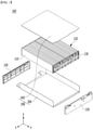
- FIG. 1 is an exploded perspective view illustrating a battery module according to an embodiment of the present disclosure.
- FIG. 2 is a perspective view illustrating a state in which elements constituting the battery module of FIG. 1 are coupled to each other.
- a battery module 100 includes a battery cell stack 120 in which a plurality of the battery cells 110 are stacked, a module frame 200 for housing the battery cell stack 120, and end plates 150 for covering front and rear surfaces of the battery cell stack 120. Further, the battery module 100 further includes a busbar frame 130 located between the end plates 150 and the battery cell stack 120.
- the module frame 200 includes a U-shaped frame 300, of which an upper surface, a front surface, and a rear surface are opened, and an upper plate 400 for covering an upper part of the battery cell stack 120.
- the module frame 200 is not limited thereto and may be replaced by a frame of another shape, such as an L-shaped frame or a mono frame surrounding the battery cell stack 120 excluding front and rear surfaces thereof.
- the busbar frame 130 may include parts surrounding lower ends of the front and rear surfaces of the battery cell stack 120 stacked in parallel, thereby protecting the battery cell stack 120 from an external impact and improving the insulation performance of the battery cell stack 120.
- the battery module 100 includes a large-area module in which the battery cell stack 120 includes a relatively larger number of battery cells as compared with the existing battery module.
- the horizontal length of the battery module becomes relatively longer.
- the horizontal length of the battery module may mean a length in a direction in which the battery cells are stacked.
- busbar frame 130 included in the battery module 100 will be described in detail in comparison with a comparative example.
- FIG. 3 is a view illustrating a busbar frame in a battery module according to a comparative example.
- FIG. 4 is a view illustrating a molding defect section in the busbar frame of FIG. 3 .
- the busbar frame 13 included in the battery module has a support part 14 that can surround at least a partial region of bottom surfaces of the front and rear surfaces of the battery cell stack (not illustrated).
- the support part 14 is extended from the busbar frame 13 in a direction that is perpendicular to the busbar frame 13.
- the busbar frame 13 in order to mount a busbar frame 13 on the large-area module, the busbar frame 13 also have to be increased in size as it progresses in a horizontal direction of the battery module, and accordingly, the support part 14 of the busbar frame 13 also has to be increased in size.
- an unmolded section 14a may be caused in a partial region of the support part 14.
- the unmolded section 14a means that the partial region of the support part 14 is not subjected to injection molding due to a thin thickness of the support part 14.
- the total weight of the module and thermal resistance increase, heat generation caused from the battery cell stack 120 is not sufficiently discharged to the outside, and the danger of a fire due to heat generation may increase. Further, as the application amount of the thermally conductive resin increases, the manufacturing costs and the manufacturing time may increase.
- the busbar frame which is configured to prevent formation of a part such as unmolded section 14a of the support part 14 according to the above-mentioned comparative example, will be described.
- FIG. 5 is a view illustrating a busbar frame in the battery module according to the embodiment of the present disclosure.
- FIG. 6 is an enlarged view of region A of FIG. 5 .
- the busbar frame 130 included in the battery module 100 may have the support part 140 that can surround at least a partial region of bottom surfaces of the front and rear surfaces of the battery cell stack 120. Further, the busbar frame 130 may have the support part 140 that can surround at least a partial region of bottom surfaces of the front and rear surfaces of the battery cell stack 120.
- each of the battery cells 110 of the battery cell stack 120 may include a protrusion (not illustrated) that faces the bottom surface of the frame 100, and the support part 140 can surround the protrusions (not illustrated) formed in the battery cells 110. Accordingly, the support part 140 can protect the protrusion (not illustrated) from an external impact and can improve the insulation performances of the battery cells 110.
- the support part 140 is extended from the busbar frame 130 in a lengthwise direction of the battery cells. Further, the support part 140 is extended so as to surround the bottom surfaces of the front and rear surfaces of the battery cell stack 120. Further, the support part 140 is extended so as to surround the protrusions (not illustrated) formed in the battery cells 110 of the battery cell stack 120.
- the support part 140 may include an extension region 141 and at least two protrusion regions 145 formed on the extension region 141.
- the extension region 141 may be a region extending from the busbar frame 130 in a direction that is perpendicular to the busbar frame 130.
- the protrusion regions 145 are regions protruding from the extension region 141 toward the battery cell stack 120. At least two protrusion regions 145 may be spaced apart from each other in a direction in which the battery cells 110 of the battery cell stack 120 are stacked.
- the protrusions region 145 can perform the role of reinforcing a thickness of the extension region 141.
- the support part 140 may be injection-molded, and the extension region 141 and the protrusion regions 145 may also be integrally injection-molded.
- the support part 140 needs to maintain the thin thickness in order to reduce a load that is applied to the frame 200, reduce the application amount of an insulation substance applied to the frame 200, and have a proper thermal resistance.
- the extension region 141 is also injected by further extending in the stacking direction of the battery cell stack. Accordingly, as the extension region 141 maintains the thin thickness and also extends in the stacking direction of the battery cell stack more than the existing length, the unmolded section 14a as shown in FIG. 4 may be occurred.
- the protrusion regions 145 may be partially formed in a section in which there is a high possibility of causing the unmolded section 14a to occur in the extension region 141. Further, the protrusion regions 145 may be formed at the location corresponding to the unmolded section formed in the extension region 141. Further, in order to prevent the unmolded section 14a from being occurred in the extension region 141, the protrusion regions 145 may be formed to be spaced apart from each other at a regular interval on the extension region 141.
- the thickness of a partial section of the extension region 141 may be reinforced due to the protrusion region 145. That is, while the support part 140 does not increase the thickness of the extension region 141, a vulnerable portion due to unmolding due to the widened areas may be supplemented by the protrusion region 145. Further, while the protrusion region 145 may be integrally molded as the busbar frame 140 is injection-molded, and thus the method for manufacturing may become simpler and the manufacturing time may become shorter.
- FIG. 7 is a view illustrating a cross-section taken along an xy plane of FIG. 2 .
- FIG. 8 is a sectional view of region B of FIG. 7 , taken along the cutting line a-a'.
- the support part 140 may have the extension region 141 and the protrusion region 145, and the protrusion regions 145 may be formed at the location corresponding to a region between at least two battery cells 110.
- each of the battery cells 110 of the battery cell stack 120 includes a protrusion 110P.
- the protrusion regions 145 may be formed at the location corresponding to the region between the protrusions 110P formed at two or more of the battery cells 110, respectively.
- the support part 140 forms the protrusion region 145 in order to prevent the unmolded section due to the increase of size, and forms the protrusion region 145 at the location corresponding to the region between the protrusions 110P of the battery cells 110 to thereby minimize an empty space between the support part 140 and the battery cell stack 120.
- the protrusion region 145 of the support part 140 may also protect side surfaces of the protrusion 110P and thus, protection performance from the external impact about the protrusion 110P of the battery cell 110 can be improved.
- an empty space between the support part 140 and the battery cell stack 120 is minimized and thus, the thickness of the thermally conductive resin layer applied to the frame 200 can be maintained similar to the existing thickness thereof, the total weight and thermal resistance may not increase.
- the protrusion region 145 may have a symmetrical shape. Further, the protrusion region 145 may have a region in which at least one layer is formed to be curved on the extension region 141. Further, the protrusion region 145 may have a region in which at least one layer is are formed to be stacked on the extension region 141. In particular, the region formed through stacking may be smoothly connected to the extension region 141. Here, the protrusion region 145 may have a region in which at least one layer having shorter length as compared with the extension region 141 is formed on the extension region 141.
- the protrusion region 145 may be formed by stacking at least two layers, the length of at least two layers is smaller as compared with the extension region 141, and the length of a layer adjacent to the extension region 141 may be formed longer. Further, when the protrusion region 145 is formed at the location corresponding to a region between the protrusions 110P, the protrusion region 145 may be identical to or smaller than a region between two battery cells 110.
- the protrusion region 145 may be formed in the support part 140 to prevent an unmolded section according to the increase of size, and when the protrusion region 145 is injection-molded, the manufacturing process may become simple and the manufacturing time may become shorter.
- FIG. 9 is a sectional view of region B of FIG. 8 , taken along the cutting line b-b'.
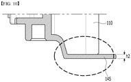
- FIG. 10 is a sectional view of region B of FIG. 8 , taken along the cutting line c-c'.
- the support part 140 may be configured such that a thickness h1 of the extension region 141 is smaller as compared with a thickness h2 of the support part at the location in which the protrusion region 145 is formed.
- the extension region 141 surrounds the protrusion 110P formed at the battery cell 110 of the battery cell stack 120 and thus, must have a thin thickness as compared with the protrusion region 145.
- the support part 140 corresponds to the extension region 141 and a lower surface of the protrusion 110P
- the protrusion region 145 corresponds to the side surfaces of the protrusion 110P and thus, the protection performance from an external impact about the protrusion 110P of the battery cell 110 can be improved.
Landscapes
- Chemical & Material Sciences (AREA)
- Chemical Kinetics & Catalysis (AREA)
- Electrochemistry (AREA)
- General Chemical & Material Sciences (AREA)
- Battery Mounting, Suspending (AREA)
- Sealing Battery Cases Or Jackets (AREA)
- Connection Of Batteries Or Terminals (AREA)
Abstract
Description
- This application claims the benefit of
Korean Patent Application No. 10-2020-0050725 filed on April 27, 2020 - The present disclosure relates to a battery module and a battery pack including the same, and more particularly to a battery module that improves a molding defect caused by the size increase of a component, and a battery pack including the same.
- As technology development and demands for mobile devices increase, the demand for batteries as energy sources is rapidly increasing. In particular, a secondary battery has attracted considerable attention as an energy source for power-driven devices, such as an electric bicycle, an electric vehicle, and a hybrid electric vehicle, as well as an energy source for mobile devices, such as a mobile phone, a digital camera, a laptop computer and a wearable device.
- Small-sized mobile devices use one or several battery cells for each device, whereas middle- or large-sized devices such as vehicles require high power and large capacity. A middle or large-sized battery module is preferably manufactured so as to have as small a size and weight as possible. For this reason, a prismatic battery, a pouch-type battery or the like, which can be stacked with high integration and has a small weight relative to capacity, is usually used as a battery cell of the middle or large-sized battery module. Therefore, a middle or large-sized battery module in which a large number of battery cells are electrically connected is used, and gradually, the need for installing many more battery cells within a battery module is increasing.
- On the other hand, as the need for the battery module to include many more battery cells is increased, the size of the component included in the battery module also needs to be increased. However, among the components included in the battery module, the component formed by injection molding causes an unmolded section to occur as the size increases. Accordingly, in order to realize the size increase of the battery module, there is a need to improve a molding defect in the unmolded section.
- It is an object of the present disclosure to provide a battery module that can improve a molding defect of a component caused by the size increase of the battery module, and a battery pack including the same.
- The objects of the present disclosure are not limited to the aforementioned objects, and other objects which are not described herein should be clearly understood by those skilled in the art from the following detailed description and the accompanying drawings.
- According to one embodiment of the present disclosure, there is provided a battery module comprising a battery cell stack in which a plurality of battery cells are stacked, and a busbar frame located on front and rear surfaces of the battery cell stack, wherein the busbar frame comprises a support part surrounding at least a portion of a bottom surface of the battery cell stack, and wherein the support part comprises an extension region extending from the busbar frame to a lengthwise direction of a battery cell, and a protrusion region formed on the extension region.
- The protrusion region may include at least two protrusion regions, with the at least two protrusion regions being spaced apart from each other in a direction corresponding to a direction in which the battery cells are stacked.
- The protrusion region may be formed at a location corresponding to an unmolded section formed in the support part.
- The protrusion region may be formed at a location corresponding to a region between two battery cells in the battery cell stack.
- The protrusion region may be protruded from the extension region toward the battery cell stack.
- The protrusion region may have a symmetrical shape.
- The protrusion region may be formed such that at least one layer is stacked on the extension region.
- The protrusion region may be formed such that at least two layers are stacked on the extension region, with a length of a layer adjacent to the extension region being formed longer.
- The length of the layer adjacent to the extension region may be identical to or smaller than a region between two battery cells in the battery cell stack.
- A thickness of the extension region may be smaller than a thickness of the support part of the location, at which the protrusion region is formed.
- According to one embodiment of the present disclosure, there is provided a battery pack comprising the above-mentioned battery module.
- According to the embodiments of the present disclosure, the molding defect caused when the busbar frame is injection-molded can be improved by reinforcing a thickness of a partial section of the busbar frame according to the size increase of the battery module.
- Further, an application amount of the thermally conductive resin can be prevented from being increased due to an increase in the entire thickness, through a partial reinforcement of the thickness of the busbar frame.
- The effects of the present disclosure are not limited to the effects mentioned above and additional other effects not described above will be clearly understood from the description of the appended claims by those skilled in the art.
-
-
FIG. 1 is an exploded perspective view illustrating a battery module according to an embodiment of the present disclosure; -
FIG. 2 is a perspective view illustrating a state in which elements constituting the battery module ofFIG. 1 are coupled to each other; -
FIG. 3 is a view illustrating a busbar frame in a battery module according to a comparative example. -
FIG. 4 is a view illustrating a molding defect section in the busbar frame ofFIG. 3 ; -
FIG. 5 is a view illustrating a busbar frame in the battery module according to the embodiment of the present disclosure; -
FIG. 6 is an enlarged view of region A ofFIG. 5 ; -
FIG. 7 is a view illustrating a cross-section taken along an xy plane ofFIG. 2 ; -
FIG. 8 is a sectional view of region B ofFIG. 7 , taken along the cutting line a-a'; -
FIG. 9 is a sectional view of region B ofFIG. 8 , taken along the cutting line b-b'; and -
FIG. 10 is a sectional view of region B ofFIG. 8 , taken along the cutting line c-c'. - Hereinafter, various embodiments of the present disclosure will be described in detail with reference to the accompanying drawings so that those skilled in the art can easily carry out them. The present disclosure may be modified in various different ways, and is not limited to the embodiments set forth herein.
- Portions that are irrelevant to the description will be omitted to clearly describe the present disclosure, and like reference numerals designate like elements throughout the specification.
- Further, in the figures, the size and thickness of each element are arbitrarily illustrated for convenience of description, and the present disclosure is not necessarily limited to those illustrated in the figures. In the figures, the thickness of layers, regions, etc. are exaggerated for clarity. In the figures, for convenience of description, the thicknesses of some layers and regions are shown to be exaggerated.
- In addition, it will be understood that when an element such as a layer, film, region, or plate is referred to as being "on" or "above" another element, it can be directly on the other element or intervening elements may also be present. In contrast, when an element is referred to as being "directly on" another element, it means that other intervening elements are not present. Further, the word "on" or "above" means disposed on or below a reference portion, and does not necessarily mean being disposed on the upper end of the reference portion toward the opposite direction of gravity.
- Further, throughout the specification, when a portion is referred to as "including" a certain component, it means that it can further include other components, without excluding the other components, unless otherwise stated.
- Further, throughout the specification, when referred to as "planar", it means when a target portion is viewed from the upper side, and when referred to as "cross-sectional", it means when a target portion is viewed from the side of a cross section cut vertically.
- In the following, an electrode for a secondary battery according to an embodiment of the present disclosure will be described. However, the description herein is made based on the front surface of the front and rear surfaces of the battery module, but is not necessarily limited thereto, and even in the case of the rear surface, the same or similar contents may be described.
-
FIG. 1 is an exploded perspective view illustrating a battery module according to an embodiment of the present disclosure.FIG. 2 is a perspective view illustrating a state in which elements constituting the battery module ofFIG. 1 are coupled to each other. - Referring to
FIG. 1 and2 , abattery module 100 according to the present embodiment includes abattery cell stack 120 in which a plurality of thebattery cells 110 are stacked, amodule frame 200 for housing thebattery cell stack 120, andend plates 150 for covering front and rear surfaces of thebattery cell stack 120. Further, thebattery module 100 further includes abusbar frame 130 located between theend plates 150 and thebattery cell stack 120. - As an example, the
module frame 200 includes aU-shaped frame 300, of which an upper surface, a front surface, and a rear surface are opened, and anupper plate 400 for covering an upper part of thebattery cell stack 120. However, themodule frame 200 is not limited thereto and may be replaced by a frame of another shape, such as an L-shaped frame or a mono frame surrounding thebattery cell stack 120 excluding front and rear surfaces thereof. - The
busbar frame 130 may include parts surrounding lower ends of the front and rear surfaces of thebattery cell stack 120 stacked in parallel, thereby protecting thebattery cell stack 120 from an external impact and improving the insulation performance of thebattery cell stack 120. - However, the
battery module 100 according to an embodiment of the present disclosure includes a large-area module in which thebattery cell stack 120 includes a relatively larger number of battery cells as compared with the existing battery module. In the case of the large-area module, the horizontal length of the battery module becomes relatively longer. Here, the horizontal length of the battery module may mean a length in a direction in which the battery cells are stacked. - Hereinafter, the
busbar frame 130 included in thebattery module 100 according to an embodiment of the present disclosure will be described in detail in comparison with a comparative example. -
FIG. 3 is a view illustrating a busbar frame in a battery module according to a comparative example.FIG. 4 is a view illustrating a molding defect section in the busbar frame ofFIG. 3 . - Referring to
FIGS. 3 and4 , thebusbar frame 13 included in the battery module (not illustrated) has asupport part 14 that can surround at least a partial region of bottom surfaces of the front and rear surfaces of the battery cell stack (not illustrated). Thesupport part 14 is extended from thebusbar frame 13 in a direction that is perpendicular to thebusbar frame 13. - However, in order to mount a
busbar frame 13 on the large-area module, thebusbar frame 13 also have to be increased in size as it progresses in a horizontal direction of the battery module, and accordingly, thesupport part 14 of thebusbar frame 13 also has to be increased in size. Referring toFIG. 4 , when the upsizedbusbar frame 13 is injection-molded, anunmolded section 14a may be caused in a partial region of thesupport part 14. Here, theunmolded section 14a means that the partial region of thesupport part 14 is not subjected to injection molding due to a thin thickness of thesupport part 14. - In order to prevent the
unmolded section 14a of thesupport part 14 from being occurred, when an entire thickness of thesupport part 14 increases, a total weight of thebusbar frame 13 due to thesupport part 14 increases and thus, a load applied to theframe 200 may increase and a damage may be caused due to weight. Further, in this case, because the battery cell stack supported by thesupport part 14 also becomes far away from a bottom part of the module frame due to the increase in thickness of thesupport part 14, an application amount of a thermally conductive resin, which is used to form the thermally conductive resin layer between the battery cell stack and the module frame, may also increase. Accordingly, the total weight of the module and thermal resistance increase, heat generation caused from thebattery cell stack 120 is not sufficiently discharged to the outside, and the danger of a fire due to heat generation may increase. Further, as the application amount of the thermally conductive resin increases, the manufacturing costs and the manufacturing time may increase. - Thus, in the embodiment of the present disclosure, at the time of forming the upsized
busbar frame 130 for being mounted on the large-area module by injection molding, the busbar frame, which is configured to prevent formation of a part such asunmolded section 14a of thesupport part 14 according to the above-mentioned comparative example, will be described. -
FIG. 5 is a view illustrating a busbar frame in the battery module according to the embodiment of the present disclosure.FIG. 6 is an enlarged view of region A ofFIG. 5 . - Referring to
FIGS. 1 ,2 ,5, and 6 , thebusbar frame 130 included in thebattery module 100 may have thesupport part 140 that can surround at least a partial region of bottom surfaces of the front and rear surfaces of thebattery cell stack 120. Further, thebusbar frame 130 may have thesupport part 140 that can surround at least a partial region of bottom surfaces of the front and rear surfaces of thebattery cell stack 120. In particular, each of thebattery cells 110 of thebattery cell stack 120 may include a protrusion (not illustrated) that faces the bottom surface of theframe 100, and thesupport part 140 can surround the protrusions (not illustrated) formed in thebattery cells 110. Accordingly, thesupport part 140 can protect the protrusion (not illustrated) from an external impact and can improve the insulation performances of thebattery cells 110. - The
support part 140 is extended from thebusbar frame 130 in a lengthwise direction of the battery cells. Further, thesupport part 140 is extended so as to surround the bottom surfaces of the front and rear surfaces of thebattery cell stack 120. Further, thesupport part 140 is extended so as to surround the protrusions (not illustrated) formed in thebattery cells 110 of thebattery cell stack 120. - The
support part 140 may include anextension region 141 and at least twoprotrusion regions 145 formed on theextension region 141. Theextension region 141 may be a region extending from thebusbar frame 130 in a direction that is perpendicular to thebusbar frame 130. Theprotrusion regions 145 are regions protruding from theextension region 141 toward thebattery cell stack 120. At least twoprotrusion regions 145 may be spaced apart from each other in a direction in which thebattery cells 110 of thebattery cell stack 120 are stacked. Here, theprotrusions region 145 can perform the role of reinforcing a thickness of theextension region 141. - The
support part 140 may be injection-molded, and theextension region 141 and theprotrusion regions 145 may also be integrally injection-molded. Thesupport part 140 needs to maintain the thin thickness in order to reduce a load that is applied to theframe 200, reduce the application amount of an insulation substance applied to theframe 200, and have a proper thermal resistance. However, as thebusbar frame 130 is injected by further extending in a staking direction of the battery cell stack so as to be mounted on the large-area module, theextension region 141 is also injected by further extending in the stacking direction of the battery cell stack. Accordingly, as theextension region 141 maintains the thin thickness and also extends in the stacking direction of the battery cell stack more than the existing length, theunmolded section 14a as shown inFIG. 4 may be occurred. - Referring to
FIGS. 1 , and4 to 6 , in order to prevent theunmolded section 14a as inFIG. 4 from being occurred during injection molding of thesupport part 140, theprotrusion regions 145 may be partially formed in a section in which there is a high possibility of causing theunmolded section 14a to occur in theextension region 141. Further, theprotrusion regions 145 may be formed at the location corresponding to the unmolded section formed in theextension region 141. Further, in order to prevent theunmolded section 14a from being occurred in theextension region 141, theprotrusion regions 145 may be formed to be spaced apart from each other at a regular interval on theextension region 141. - Accordingly, while the
support part 140 included in the upsizedbusbar frame 140 maintains the thin thickness, the thickness of a partial section of theextension region 141 may be reinforced due to theprotrusion region 145. That is, while thesupport part 140 does not increase the thickness of theextension region 141, a vulnerable portion due to unmolding due to the widened areas may be supplemented by theprotrusion region 145. Further, while theprotrusion region 145 may be integrally molded as thebusbar frame 140 is injection-molded, and thus the method for manufacturing may become simpler and the manufacturing time may become shorter. -
FIG. 7 is a view illustrating a cross-section taken along an xy plane ofFIG. 2 .FIG. 8 is a sectional view of region B ofFIG. 7 , taken along the cutting line a-a'. - Referring to
FIGS. 1 , and5 to 8 , thesupport part 140 may have theextension region 141 and theprotrusion region 145, and theprotrusion regions 145 may be formed at the location corresponding to a region between at least twobattery cells 110. As an example, each of thebattery cells 110 of thebattery cell stack 120 includes aprotrusion 110P. Theprotrusion regions 145 may be formed at the location corresponding to the region between theprotrusions 110P formed at two or more of thebattery cells 110, respectively. - Accordingly, while the
support part 140 forms theprotrusion region 145 in order to prevent the unmolded section due to the increase of size, and forms theprotrusion region 145 at the location corresponding to the region between theprotrusions 110P of thebattery cells 110 to thereby minimize an empty space between thesupport part 140 and thebattery cell stack 120. Further, theprotrusion region 145 of thesupport part 140 may also protect side surfaces of theprotrusion 110P and thus, protection performance from the external impact about theprotrusion 110P of thebattery cell 110 can be improved. Further, because an empty space between thesupport part 140 and thebattery cell stack 120 is minimized and thus, the thickness of the thermally conductive resin layer applied to theframe 200 can be maintained similar to the existing thickness thereof, the total weight and thermal resistance may not increase. - Referring to
FIGS. 1 , and5 to 8 , theprotrusion region 145 may have a symmetrical shape. Further, theprotrusion region 145 may have a region in which at least one layer is formed to be curved on theextension region 141. Further, theprotrusion region 145 may have a region in which at least one layer is are formed to be stacked on theextension region 141. In particular, the region formed through stacking may be smoothly connected to theextension region 141. Here, theprotrusion region 145 may have a region in which at least one layer having shorter length as compared with theextension region 141 is formed on theextension region 141. Further, theprotrusion region 145 may be formed by stacking at least two layers, the length of at least two layers is smaller as compared with theextension region 141, and the length of a layer adjacent to theextension region 141 may be formed longer. Further, when theprotrusion region 145 is formed at the location corresponding to a region between theprotrusions 110P, theprotrusion region 145 may be identical to or smaller than a region between twobattery cells 110. - Accordingly, the
protrusion region 145 may be formed in thesupport part 140 to prevent an unmolded section according to the increase of size, and when theprotrusion region 145 is injection-molded, the manufacturing process may become simple and the manufacturing time may become shorter. -
FIG. 9 is a sectional view of region B ofFIG. 8 , taken along the cutting line b-b'.FIG. 10 is a sectional view of region B ofFIG. 8 , taken along the cutting line c-c'. - Referring to
FIGS. 1 , and5 to 10 , thesupport part 140 may be configured such that a thickness h1 of theextension region 141 is smaller as compared with a thickness h2 of the support part at the location in which theprotrusion region 145 is formed. This is because theextension region 141 surrounds theprotrusion 110P formed at thebattery cell 110 of thebattery cell stack 120 and thus, must have a thin thickness as compared with theprotrusion region 145. Accordingly, thesupport part 140 corresponds to theextension region 141 and a lower surface of theprotrusion 110P, and theprotrusion region 145 corresponds to the side surfaces of theprotrusion 110P and thus, the protection performance from an external impact about theprotrusion 110P of thebattery cell 110 can be improved. - Therefore, according to the invention described herein, despite the expansion of the area of the
support part 140 due to the size increase of thebusbar frame 130, not only the protection and insulation performances of theprotrusion 110P of thebattery cell 110, which are the existing purposes of thesupport part 140, can be realized, but also through theprotrusion region 145, the unmolded section of thesupport part 140 can be reinforced, the rigidity can be improved, and the protection of theprotrusion 110P can be strengthened. - Although the preferred embodiments of the present disclosure have been described in detail above, the scope of the present disclosure is not limited thereto, and various modifications and improvements of those skilled in the art using the basic concepts of the present disclosure defined in the following claims also belong to the scope of rights.
-
- 100:
- battery module
- 110:
- battery cell
- 120:
- battery cell stack
- 130:
- busbar frame
- 140:
- support part
- 200:
- module frame
Claims (11)
- A battery module comprising:a battery cell stack in which a plurality of battery cells are stacked; anda busbar frame located on front and rear surfaces of the battery cell stack,wherein the busbar frame comprises a support part surrounding at least a portion of a bottom surface of the battery cell stack, andwherein the support part comprises an extension region extending from the busbar frame to a lengthwise direction of a battery cell, and a protrusion region formed on the extension region.
- The battery module according to claim 1,
wherein the protrusion region comprises at least two protrusion regions, with the at least two protrusion regions being spaced apart from each other in a direction corresponding to a direction in which the battery cells are stacked. - The battery module according to claim 1,
wherein the protrusion region is formed at a location corresponding to an unmolded section formed in the support part. - The battery module according to claim 1,
wherein the protrusion region is formed at a location corresponding to a region between two battery cells in the battery cell stack. - The battery module according to claim 1,
wherein the protrusion region is protruded from the extension region toward the battery cell stack. - The battery module according to claim 5,
wherein the protrusion region has a symmetrical shape. - The battery module according to claim 5,
wherein the protrusion region is formed such that at least one layer is stacked on the extension region. - The battery module according to claim 7,
wherein the protrusion region is formed such that at least two layers are stacked on the extension region, with a length of a layer adjacent to the extension region being formed longer. - The battery module according to claim 8,
wherein the length of the layer adjacent to the extension region is identical to or smaller than a region between two battery cells in the battery cell stack. - The battery module according to claim 1,
wherein a thickness of the extension region is smaller than a thickness of the support part of the location, at which the protrusion region is formed. - A battery pack comprising the battery module according to claim 1.
Applications Claiming Priority (2)
| Application Number | Priority Date | Filing Date | Title |
|---|---|---|---|
| KR1020200050725A KR20210132397A (en) | 2020-04-27 | 2020-04-27 | Battery module and battery pack including the same |
| PCT/KR2021/002256 WO2021221284A1 (en) | 2020-04-27 | 2021-02-23 | Battery module and battery pack comprising same |
Publications (2)
| Publication Number | Publication Date |
|---|---|
| EP3958380A1 true EP3958380A1 (en) | 2022-02-23 |
| EP3958380A4 EP3958380A4 (en) | 2022-08-10 |
Family
ID=78332051
Family Applications (1)
| Application Number | Title | Priority Date | Filing Date |
|---|---|---|---|
| EP21797175.3A Pending EP3958380A4 (en) | 2020-04-27 | 2021-02-23 | BATTERY MODULE AND BATTERY PACK WITH BATTERY MODULE |
Country Status (6)
| Country | Link |
|---|---|
| US (1) | US12327882B2 (en) |
| EP (1) | EP3958380A4 (en) |
| JP (1) | JP7337196B2 (en) |
| KR (1) | KR20210132397A (en) |
| CN (1) | CN113892212B (en) |
| WO (1) | WO2021221284A1 (en) |
Cited By (1)
| Publication number | Priority date | Publication date | Assignee | Title |
|---|---|---|---|---|
| US12087928B2 (en) | 2019-06-12 | 2024-09-10 | Lg Energy Solution, Ltd. | Battery module and battery pack including the same |
Family Cites Families (18)
| Publication number | Priority date | Publication date | Assignee | Title |
|---|---|---|---|---|
| KR100920207B1 (en) * | 2006-11-27 | 2009-10-06 | 주식회사 엘지화학 | Power switching module for manufacturing battery module assembly |
| KR20150024724A (en) | 2013-08-27 | 2015-03-09 | 삼성에스디아이 주식회사 | Battery pack |
| KR101841801B1 (en) * | 2014-06-11 | 2018-05-04 | 주식회사 엘지화학 | Battery pack having bushing for coupling end plate |
| KR101817237B1 (en) | 2014-12-24 | 2018-01-11 | 주식회사 엘지화학 | Method for welding of electrode-leads & secondary battery module utilizing thereof |
| KR101935013B1 (en) | 2015-09-25 | 2019-01-03 | 주식회사 엘지화학 | Battery module, battery pack comprising the battery module and vehicle comprising the battery pack |
| JP6441265B2 (en) * | 2015-10-23 | 2018-12-19 | 矢崎総業株式会社 | Bus bar module and battery pack |
| KR102468338B1 (en) | 2015-11-02 | 2022-11-16 | 삼성에스디아이 주식회사 | Rechargeable battery module |
| KR102223514B1 (en) * | 2015-12-29 | 2021-03-05 | 에스케이이노베이션 주식회사 | Battery module |
| KR102148993B1 (en) * | 2017-06-13 | 2020-08-27 | 주식회사 엘지화학 | Battery module |
| US10431803B2 (en) * | 2017-08-07 | 2019-10-01 | Ford Global Technologies, Llc | Traction battery assembly having multipiece busbar module |
| JP6567620B2 (en) | 2017-10-03 | 2019-08-28 | カルソニックカンセイ株式会社 | Manufacturing method of assembled battery and assembled battery |
| KR102259416B1 (en) * | 2017-12-14 | 2021-06-01 | 주식회사 엘지에너지솔루션 | Battery Module Having Bus bar Assembly |
| KR102270828B1 (en) | 2017-12-19 | 2021-06-29 | 주식회사 엘지에너지솔루션 | Battery Module Having Bus-Bar Assembly |
| DE102018133391A1 (en) * | 2017-12-26 | 2019-06-27 | Sk Innovation Co., Ltd. | Battery module and manufacturing method thereof |
| KR102150679B1 (en) | 2018-03-13 | 2020-09-01 | 주식회사 엘지화학 | Battery module, battery pack comprising the battery module and vehicle comprising the battery pack |
| KR102354401B1 (en) | 2018-04-25 | 2022-01-20 | 주식회사 엘지에너지솔루션 | Battery module and battery pack including the same |
| KR102317638B1 (en) * | 2018-12-05 | 2021-10-25 | 주식회사 엘지에너지솔루션 | Battery module having protection structure of cell stack |
| CN109742285A (en) | 2019-01-16 | 2019-05-10 | 合肥国轩高科动力能源有限公司 | A soft pack battery module and its assembly method |
-
2020
- 2020-04-27 KR KR1020200050725A patent/KR20210132397A/en active Pending
-
2021
- 2021-02-23 US US17/612,842 patent/US12327882B2/en active Active
- 2021-02-23 EP EP21797175.3A patent/EP3958380A4/en active Pending
- 2021-02-23 WO PCT/KR2021/002256 patent/WO2021221284A1/en not_active Ceased
- 2021-02-23 JP JP2021568958A patent/JP7337196B2/en active Active
- 2021-02-23 CN CN202180003613.9A patent/CN113892212B/en active Active
Cited By (1)
| Publication number | Priority date | Publication date | Assignee | Title |
|---|---|---|---|---|
| US12087928B2 (en) | 2019-06-12 | 2024-09-10 | Lg Energy Solution, Ltd. | Battery module and battery pack including the same |
Also Published As
| Publication number | Publication date |
|---|---|
| JP2022534690A (en) | 2022-08-03 |
| CN113892212B (en) | 2024-04-16 |
| KR20210132397A (en) | 2021-11-04 |
| EP3958380A4 (en) | 2022-08-10 |
| US12327882B2 (en) | 2025-06-10 |
| JP7337196B2 (en) | 2023-09-01 |
| US20220238964A1 (en) | 2022-07-28 |
| WO2021221284A1 (en) | 2021-11-04 |
| CN113892212A (en) | 2022-01-04 |
Similar Documents
| Publication | Publication Date | Title |
|---|---|---|
| EP3796462B1 (en) | Battery module, manufacturing method thereof and battery pack including battery module | |
| US12580258B2 (en) | Battery module and battery pack including the same | |
| US20250149673A1 (en) | Battery Module, Manufacturing Method Thereof and Battery Pack Including Battery Module | |
| EP3930079B1 (en) | Battery module and battery pack including the same | |
| EP4170796A1 (en) | Battery module and battery pack including same | |
| US12224416B2 (en) | Battery module and battery pack including the same | |
| EP3937303A1 (en) | Battery module and battery pack including same | |
| US12451540B2 (en) | Battery module and battery pack including the same | |
| EP4057433A1 (en) | Battery module and battery pack including same | |
| EP3958381A1 (en) | Battery module and battery pack comprising same | |
| CN114930624A (en) | Battery module and battery pack including the same | |
| US12327882B2 (en) | Battery module and battery pack including the same | |
| CN114846680B (en) | Battery module and battery pack including the battery module | |
| CN115088121B (en) | Battery module, battery pack including the battery module, and device including the battery pack | |
| EP4120441B1 (en) | Battery module and battery pack including the same | |
| US12500311B2 (en) | Battery module and battery pack including the same | |
| CN114503350A (en) | Battery module and method of manufacturing the same |
Legal Events
| Date | Code | Title | Description |
|---|---|---|---|
| STAA | Information on the status of an ep patent application or granted ep patent |
Free format text: STATUS: THE INTERNATIONAL PUBLICATION HAS BEEN MADE |
|
| PUAI | Public reference made under article 153(3) epc to a published international application that has entered the european phase |
Free format text: ORIGINAL CODE: 0009012 |
|
| STAA | Information on the status of an ep patent application or granted ep patent |
Free format text: STATUS: REQUEST FOR EXAMINATION WAS MADE |
|
| 17P | Request for examination filed |
Effective date: 20211118 |
|
| AK | Designated contracting states |
Kind code of ref document: A1 Designated state(s): AL AT BE BG CH CY CZ DE DK EE ES FI FR GB GR HR HU IE IS IT LI LT LU LV MC MK MT NL NO PL PT RO RS SE SI SK SM TR |
|
| RAP3 | Party data changed (applicant data changed or rights of an application transferred) |
Owner name: LG ENERGY SOLUTION, LTD. |
|
| A4 | Supplementary search report drawn up and despatched |
Effective date: 20220711 |
|
| RIC1 | Information provided on ipc code assigned before grant |
Ipc: H01M 50/502 20210101ALI20220705BHEP Ipc: H01M 50/20 20210101AFI20220705BHEP |
|
| DAV | Request for validation of the european patent (deleted) | ||
| DAX | Request for extension of the european patent (deleted) | ||
| STAA | Information on the status of an ep patent application or granted ep patent |
Free format text: STATUS: EXAMINATION IS IN PROGRESS |
|
| 17Q | First examination report despatched |
Effective date: 20241220 |