EP3958377A1 - Battery module - Google Patents
Battery module Download PDFInfo
- Publication number
- EP3958377A1 EP3958377A1 EP20892480.3A EP20892480A EP3958377A1 EP 3958377 A1 EP3958377 A1 EP 3958377A1 EP 20892480 A EP20892480 A EP 20892480A EP 3958377 A1 EP3958377 A1 EP 3958377A1
- Authority
- EP
- European Patent Office
- Prior art keywords
- bottom plate
- battery module
- cell stack
- thermally conductive
- fence member
- Prior art date
- Legal status (The legal status is an assumption and is not a legal conclusion. Google has not performed a legal analysis and makes no representation as to the accuracy of the status listed.)
- Granted
Links
Images








Classifications
-
- H—ELECTRICITY
- H01—ELECTRIC ELEMENTS
- H01M—PROCESSES OR MEANS, e.g. BATTERIES, FOR THE DIRECT CONVERSION OF CHEMICAL ENERGY INTO ELECTRICAL ENERGY
- H01M50/00—Constructional details or processes of manufacture of the non-active parts of electrochemical cells other than fuel cells, e.g. hybrid cells
- H01M50/20—Mountings; Secondary casings or frames; Racks, modules or packs; Suspension devices; Shock absorbers; Transport or carrying devices; Holders
- H01M50/204—Racks, modules or packs for multiple batteries or multiple cells
- H01M50/207—Racks, modules or packs for multiple batteries or multiple cells characterised by their shape
- H01M50/211—Racks, modules or packs for multiple batteries or multiple cells characterised by their shape adapted for pouch cells
-
- B—PERFORMING OPERATIONS; TRANSPORTING
- B60—VEHICLES IN GENERAL
- B60L—PROPULSION OF ELECTRICALLY-PROPELLED VEHICLES; SUPPLYING ELECTRIC POWER FOR AUXILIARY EQUIPMENT OF ELECTRICALLY-PROPELLED VEHICLES; ELECTRODYNAMIC BRAKE SYSTEMS FOR VEHICLES IN GENERAL; MAGNETIC SUSPENSION OR LEVITATION FOR VEHICLES; MONITORING OPERATING VARIABLES OF ELECTRICALLY-PROPELLED VEHICLES; ELECTRIC SAFETY DEVICES FOR ELECTRICALLY-PROPELLED VEHICLES
- B60L50/00—Electric propulsion with power supplied within the vehicle
- B60L50/50—Electric propulsion with power supplied within the vehicle using propulsion power supplied by batteries or fuel cells
- B60L50/60—Electric propulsion with power supplied within the vehicle using propulsion power supplied by batteries or fuel cells using power supplied by batteries
- B60L50/64—Constructional details of batteries specially adapted for electric vehicles
-
- B—PERFORMING OPERATIONS; TRANSPORTING
- B60—VEHICLES IN GENERAL
- B60L—PROPULSION OF ELECTRICALLY-PROPELLED VEHICLES; SUPPLYING ELECTRIC POWER FOR AUXILIARY EQUIPMENT OF ELECTRICALLY-PROPELLED VEHICLES; ELECTRODYNAMIC BRAKE SYSTEMS FOR VEHICLES IN GENERAL; MAGNETIC SUSPENSION OR LEVITATION FOR VEHICLES; MONITORING OPERATING VARIABLES OF ELECTRICALLY-PROPELLED VEHICLES; ELECTRIC SAFETY DEVICES FOR ELECTRICALLY-PROPELLED VEHICLES
- B60L58/00—Methods or circuit arrangements for monitoring or controlling batteries or fuel cells, specially adapted for electric vehicles
- B60L58/10—Methods or circuit arrangements for monitoring or controlling batteries or fuel cells, specially adapted for electric vehicles for monitoring or controlling batteries
- B60L58/24—Methods or circuit arrangements for monitoring or controlling batteries or fuel cells, specially adapted for electric vehicles for monitoring or controlling batteries for controlling the temperature of batteries
- B60L58/26—Methods or circuit arrangements for monitoring or controlling batteries or fuel cells, specially adapted for electric vehicles for monitoring or controlling batteries for controlling the temperature of batteries by cooling
-
- H—ELECTRICITY
- H01—ELECTRIC ELEMENTS
- H01M—PROCESSES OR MEANS, e.g. BATTERIES, FOR THE DIRECT CONVERSION OF CHEMICAL ENERGY INTO ELECTRICAL ENERGY
- H01M10/00—Secondary cells; Manufacture thereof
- H01M10/60—Heating or cooling; Temperature control
- H01M10/61—Types of temperature control
- H01M10/613—Cooling or keeping cold
-
- H—ELECTRICITY
- H01—ELECTRIC ELEMENTS
- H01M—PROCESSES OR MEANS, e.g. BATTERIES, FOR THE DIRECT CONVERSION OF CHEMICAL ENERGY INTO ELECTRICAL ENERGY
- H01M10/00—Secondary cells; Manufacture thereof
- H01M10/60—Heating or cooling; Temperature control
- H01M10/62—Heating or cooling; Temperature control specially adapted for specific applications
- H01M10/625—Vehicles
-
- H—ELECTRICITY
- H01—ELECTRIC ELEMENTS
- H01M—PROCESSES OR MEANS, e.g. BATTERIES, FOR THE DIRECT CONVERSION OF CHEMICAL ENERGY INTO ELECTRICAL ENERGY
- H01M10/00—Secondary cells; Manufacture thereof
- H01M10/60—Heating or cooling; Temperature control
- H01M10/64—Heating or cooling; Temperature control characterised by the shape of the cells
- H01M10/647—Prismatic or flat cells, e.g. pouch cells
-
- H—ELECTRICITY
- H01—ELECTRIC ELEMENTS
- H01M—PROCESSES OR MEANS, e.g. BATTERIES, FOR THE DIRECT CONVERSION OF CHEMICAL ENERGY INTO ELECTRICAL ENERGY
- H01M10/00—Secondary cells; Manufacture thereof
- H01M10/60—Heating or cooling; Temperature control
- H01M10/65—Means for temperature control structurally associated with the cells
- H01M10/653—Means for temperature control structurally associated with the cells characterised by electrically insulating or thermally conductive materials
-
- H—ELECTRICITY
- H01—ELECTRIC ELEMENTS
- H01M—PROCESSES OR MEANS, e.g. BATTERIES, FOR THE DIRECT CONVERSION OF CHEMICAL ENERGY INTO ELECTRICAL ENERGY
- H01M10/00—Secondary cells; Manufacture thereof
- H01M10/60—Heating or cooling; Temperature control
- H01M10/65—Means for temperature control structurally associated with the cells
- H01M10/655—Solid structures for heat exchange or heat conduction
- H01M10/6554—Rods or plates
-
- H—ELECTRICITY
- H01—ELECTRIC ELEMENTS
- H01M—PROCESSES OR MEANS, e.g. BATTERIES, FOR THE DIRECT CONVERSION OF CHEMICAL ENERGY INTO ELECTRICAL ENERGY
- H01M50/00—Constructional details or processes of manufacture of the non-active parts of electrochemical cells other than fuel cells, e.g. hybrid cells
- H01M50/10—Primary casings; Jackets or wrappings
- H01M50/102—Primary casings; Jackets or wrappings characterised by their shape or physical structure
- H01M50/105—Pouches or flexible bags
-
- H—ELECTRICITY
- H01—ELECTRIC ELEMENTS
- H01M—PROCESSES OR MEANS, e.g. BATTERIES, FOR THE DIRECT CONVERSION OF CHEMICAL ENERGY INTO ELECTRICAL ENERGY
- H01M50/00—Constructional details or processes of manufacture of the non-active parts of electrochemical cells other than fuel cells, e.g. hybrid cells
- H01M50/20—Mountings; Secondary casings or frames; Racks, modules or packs; Suspension devices; Shock absorbers; Transport or carrying devices; Holders
- H01M50/244—Secondary casings; Racks; Suspension devices; Carrying devices; Holders characterised by their mounting method
-
- H—ELECTRICITY
- H01—ELECTRIC ELEMENTS
- H01M—PROCESSES OR MEANS, e.g. BATTERIES, FOR THE DIRECT CONVERSION OF CHEMICAL ENERGY INTO ELECTRICAL ENERGY
- H01M50/00—Constructional details or processes of manufacture of the non-active parts of electrochemical cells other than fuel cells, e.g. hybrid cells
- H01M50/20—Mountings; Secondary casings or frames; Racks, modules or packs; Suspension devices; Shock absorbers; Transport or carrying devices; Holders
- H01M50/249—Mountings; Secondary casings or frames; Racks, modules or packs; Suspension devices; Shock absorbers; Transport or carrying devices; Holders specially adapted for aircraft or vehicles, e.g. cars or trains
-
- H—ELECTRICITY
- H01—ELECTRIC ELEMENTS
- H01M—PROCESSES OR MEANS, e.g. BATTERIES, FOR THE DIRECT CONVERSION OF CHEMICAL ENERGY INTO ELECTRICAL ENERGY
- H01M50/00—Constructional details or processes of manufacture of the non-active parts of electrochemical cells other than fuel cells, e.g. hybrid cells
- H01M50/20—Mountings; Secondary casings or frames; Racks, modules or packs; Suspension devices; Shock absorbers; Transport or carrying devices; Holders
- H01M50/258—Modular batteries; Casings provided with means for assembling
-
- H—ELECTRICITY
- H01—ELECTRIC ELEMENTS
- H01M—PROCESSES OR MEANS, e.g. BATTERIES, FOR THE DIRECT CONVERSION OF CHEMICAL ENERGY INTO ELECTRICAL ENERGY
- H01M50/00—Constructional details or processes of manufacture of the non-active parts of electrochemical cells other than fuel cells, e.g. hybrid cells
- H01M50/20—Mountings; Secondary casings or frames; Racks, modules or packs; Suspension devices; Shock absorbers; Transport or carrying devices; Holders
- H01M50/298—Mountings; Secondary casings or frames; Racks, modules or packs; Suspension devices; Shock absorbers; Transport or carrying devices; Holders characterised by the wiring of battery packs
-
- H—ELECTRICITY
- H01—ELECTRIC ELEMENTS
- H01M—PROCESSES OR MEANS, e.g. BATTERIES, FOR THE DIRECT CONVERSION OF CHEMICAL ENERGY INTO ELECTRICAL ENERGY
- H01M50/00—Constructional details or processes of manufacture of the non-active parts of electrochemical cells other than fuel cells, e.g. hybrid cells
- H01M50/50—Current conducting connections for cells or batteries
- H01M50/502—Interconnectors for connecting terminals of adjacent batteries; Interconnectors for connecting cells outside a battery casing
- H01M50/505—Interconnectors for connecting terminals of adjacent batteries; Interconnectors for connecting cells outside a battery casing comprising a single busbar
-
- H—ELECTRICITY
- H01—ELECTRIC ELEMENTS
- H01M—PROCESSES OR MEANS, e.g. BATTERIES, FOR THE DIRECT CONVERSION OF CHEMICAL ENERGY INTO ELECTRICAL ENERGY
- H01M50/00—Constructional details or processes of manufacture of the non-active parts of electrochemical cells other than fuel cells, e.g. hybrid cells
- H01M50/50—Current conducting connections for cells or batteries
- H01M50/502—Interconnectors for connecting terminals of adjacent batteries; Interconnectors for connecting cells outside a battery casing
- H01M50/507—Interconnectors for connecting terminals of adjacent batteries; Interconnectors for connecting cells outside a battery casing comprising an arrangement of two or more busbars within a container structure, e.g. busbar modules
-
- H—ELECTRICITY
- H01—ELECTRIC ELEMENTS
- H01M—PROCESSES OR MEANS, e.g. BATTERIES, FOR THE DIRECT CONVERSION OF CHEMICAL ENERGY INTO ELECTRICAL ENERGY
- H01M2220/00—Batteries for particular applications
- H01M2220/20—Batteries in motive systems, e.g. vehicle, ship, plane
-
- Y—GENERAL TAGGING OF NEW TECHNOLOGICAL DEVELOPMENTS; GENERAL TAGGING OF CROSS-SECTIONAL TECHNOLOGIES SPANNING OVER SEVERAL SECTIONS OF THE IPC; TECHNICAL SUBJECTS COVERED BY FORMER USPC CROSS-REFERENCE ART COLLECTIONS [XRACs] AND DIGESTS
- Y02—TECHNOLOGIES OR APPLICATIONS FOR MITIGATION OR ADAPTATION AGAINST CLIMATE CHANGE
- Y02E—REDUCTION OF GREENHOUSE GAS [GHG] EMISSIONS, RELATED TO ENERGY GENERATION, TRANSMISSION OR DISTRIBUTION
- Y02E60/00—Enabling technologies; Technologies with a potential or indirect contribution to GHG emissions mitigation
- Y02E60/10—Energy storage using batteries
Definitions
- the present disclosure relates to a battery module including pouch-type secondary batteries, and more particularly, a battery module with improved cooling performance by a heat dissipation method through the cell body bottom of pouch-type secondary batteries, and a battery pack and a vehicle including the same.
- a secondary battery may be classified into a can-type secondary battery in which an electrode assembly is embedded in a metal can and a pouch-type secondary battery in which an electrode assembly is embedded in a pouch of an aluminum laminate sheet according to the shape of a case.
- secondary batteries are widely used not only in small devices such as portable electronic devices, but also in medium- and large-sized devices such as vehicles and energy storage systems.
- medium-sized devices such as vehicles and energy storage systems.
- many secondary batteries are electrically connected to increase the capacity and output.
- pouch-type secondary batteries due to advantages of pouch-type secondary batteries that are easy to stack and lightweight, pouch-type secondary batteries are widely used in medium- and large-sized devices.
- a pouch-type secondary battery is generally packaged in a battery case of a laminate sheet of aluminum and polymer resin, and thus the mechanical strength is low and it is not easy to maintain a stacked state by itself. Accordingly, when constructing a battery module including pouch-type secondary batteries, in many cases, polymer cartridges are used to protect the secondary batteries from external impacts, prevent the secondary batteries from moving and make it easy to stack the secondary batteries.
- the cartridge is generally formed in the shape of a rectangular plate with hollow center, and in this instance, the outer periphery of the pouch-type secondary battery is surrounded by the four sides.
- the battery module is constructed by stacking cartridges, and the secondary batteries may be disposed in an internal empty space created when the cartridges are stacked.
- the performance of the secondary battery may degrade, and in worse cases, explosions or fires may occur.
- the total amount of heat emitted from the secondary batteries in the narrow space may increase the temperature of the battery module faster and more severely.
- the battery module for use in automobile battery packs may be frequently exposed to direct sunlight and placed in high temperature conditions, for example, summer or desert areas. Accordingly, ensuring the stable and effective cooling performance is very important to the battery module using secondary batteries.
- a battery module is constructed by adhering and fixing a cell stack to the bottom of a module housing, instead of using a cartridge.
- secondary batteries stand vertically upright in close contact with each other.
- Thermal Interface Material TIM having good thermal conductivity is used to adhere the cell stack to the module housing, and heat from secondary battery cells is transferred to the bottom of the module housing through the lower surface of the secondary battery cells, and a heat sink is placed on the bottom of the module housing to cool the cell stack.
- the conventional battery module has the following problems. That is, in the process of placing the cell stack after applying the TIM to the bottom of the module housing, the TIM leaks out in the front-rear directions of the module housing due to the weight of the cell stack and the viscosity of the TIM. To prevent the TIM leaks, when the TIM is used in a smaller amount, the TIM does not reach the end of the secondary battery cell body, resulting in poor heat dissipation at the two ends of the secondary battery cell, and as a consequence, a difference in temperature between the central area and the two ends of the secondary battery cell increases, resulting in reduced life and performance of the cell. Accordingly, there is a need for a solution to this problem.
- the present disclosure is designed to solve the above-described problem, and therefore the present disclosure is directed to providing a battery module configured to allow a thermal interface material (TIM) such as a thermally conductive resin to be wrapped around the entire bottom of the secondary battery cell body while preventing the TIM from leaking out in the front-rear directions of the battery module when placing the cell stack on the bottom plate after applying the TIM to the bottom plate.
- a thermal interface material such as a thermally conductive resin
- a battery module includes a cell stack including a plurality of pouch-type secondary batteries standing upright in up-down directions and arranged in left-right directions, a busbar frame mounted on front and rear sides of the cell stack, a bottom plate made of a thermally conductive material, the bottom plate supporting the cell stack below the cell stack, a thermally conductive resin applied on an upper surface of the bottom plate before the cell stack is placed on the bottom plate, and a fence member disposed in front-rear directions of the bottom plate outside of the thermally conductive resin to prevent the thermally conductive resin from leaking out in front-rear directions when placing the cell stack on the bottom plate.
- the busbar frame may have a lower end portion bent and extended in an inward direction of the upper surface of the bottom plate, and the fence member may be provided at an end of the lower end portion of the busbar frame and placed on the upper surface of the bottom plate.
- Each of the pouch-type secondary batteries may include a cell body in which an electrode assembly is surrounded by a pouch case, and a cell terrace formed outside of the cell body by heat fusion of the pouch case, and the fence member may be disposed outside of the cell body.
- the fence member may have an insertion groove in which part of the cell terrace is inserted in the up-down directions.
- the fence member may be formed with a length corresponding to a widthwise direction length of the cell stack, and a greater height than a thickness of the thermally conductive resin applied to the upper surface of the bottom plate.
- the thermally conductive resin may have adhesive and thermoplastic properties.
- the fence member may be provided in a form of a foam or a pad made of rubber and attached to the bottom plate.
- the cell terrace may be formed by partially cutting to prevent contact with an upper part of the fence member.
- the busbar frame may include a first busbar frame mounted on a front side of the cell stack and a second busbar frame mounted on a rear side of the cell stack, and the fence member may include a first fence member provided at the lower end portion of the first busbar frame and a second fence member provided at the lower end portion of the second busbar frame.
- the battery module may further include a resin isolating member disposed between the first fence member and the second fence member on the upper surface of the bottom plate, the resin isolating member protruding from a surface of the bottom plate and extending in the left-right directions of the bottom plate, and the thermally conductive resin may be applied between the resin isolating member and the first fence member, and between the resin isolating member and the second fence member.
- a battery pack including at least one battery module.
- an electric vehicle including at least one battery module.
- a thermal interface material such as a thermally conductive resin to be wrapped around the entire bottom of the secondary battery cell body while preventing the thermally conductive resin from leaking out in the front-rear directions of the battery module when placing the cell stack on the bottom plate after applying the TIM to the bottom plate.
- FIG. 1 is a schematic perspective view of a battery module according to an embodiment of the present disclosure
- FIG. 2 is a diagram showing a cooling configuration of the battery module according to an embodiment of the present disclosure
- FIG. 3 is a diagram showing a cell stack, a thermally conductive resin provided on an upper surface of a bottom plate and a fence member provided in a busbar frame according to an embodiment of the present disclosure.
- the battery module includes a cell stack 10, a busbar frame 20a, 20b, a module housing 30, a thermally conductive resin 40 and a fence member 50a, 50b.
- the cell stack 10 is an assembly of secondary batteries 11, and the secondary batteries 11 are pouch-type secondary batteries.
- the pouch-type secondary batteries 11 may be arranged in the cell stack 10 in the left-right directions ( ⁇ Y) upright in the up-down directions ( ⁇ Z axis).
- the pouch-type secondary battery 11 may include an electrode assembly, an electrolyte and a pouch case to package them.
- the electrode assembly may include at least one positive electrode plate and at least one negative electrode plate with a separator interposed therebetween.
- the electrode assembly is well known in the art, and its detailed description will be omitted.
- the pouch case may include an outer insulating layer, a metal layer and an inner adhesive layer.
- the pouch case may include a metal thin film, for example, an aluminum thin film, to protect the internal components such as the electrode assembly and the electrolyte, improve the electrochemical properties of the electrode assembly and the electrolyte and enhance heat dissipation.
- the aluminum thin film may be interposed between the insulating layer formed from an insulating material and the inner adhesive layer to ensure electrical insulation with the internal components of the secondary battery 11 such as the electrode assembly and the electrolyte or other components outside the secondary battery 11.
- the pouch case may include a left pouch sheet and a right pouch sheet, and at least one of the left pouch sheet or the right pouch sheet may have a recessed inner space to form a receiving portion.
- the electrode assembly may be received in the receiving portion of the pouch.
- a sealing part is provided on the outer circumferential surfaces of the left pouch sheet and the right pouch sheet, and the inner adhesive layer of the sealing part may be welded to air-tightly seal the receiving portion in which the electrode assembly is received.
- each electrode plate of the electrode assembly has an electrode tab, and at least one electrode tab may be connected to the electrode lead 11c.
- the electrode lead 11c which is exposed to the outside of the pouch case between the sealing part of the left pouch sheet and the sealing part of the right pouch sheet, may function as an electrode terminal of the secondary battery 11.
- the receiving portion in which the electrode assembly is received in the pouch-type secondary battery 11, that is, part of the electrode assembly surrounded by the pouch case is referred to as a cell body 11a
- the sealing part of the pouch case is referred to as a cell terrace 11b.
- the busbar frame 20a and 20b may include a first busbar frame 20a mounted on the front side of the cell stack 10 and a second busbar frame 20b mounted on the rear side of the cell stack 10.
- the busbar frames 20a and 20b are provided in the shape of a plate having an area that is large enough to cover the front or rear side of the cell stack 10, and slots 23 are formed in the left-right directions on the surface of the plate into which the electrode leads 11c of the secondary battery 11 are inserted and pass through in the front-rear directions.
- a plurality of busbars 21 provided in the form of a metal plate may be provided in a predetermined pattern on the front surface of the busbar frames 20a and 20b.
- the positive electrode leads of two or more secondary batteries 11 are held together, drawn out of the busbar frames 20a and 20b frontwards through the slots 23, bent at the ends, placed in contact with the busbars 21 in parallel, and welded together.
- the negative electrode leads of two or more other secondary batteries 11 are welded to the same busbar 21. In this way, all the secondary batteries 11 of the cell stack 10 may be electrically connected in series and in parallel.
- the busbar frames 20a and 20b according to the present disclosure have lower end portions 22a and 22b bent and extended in an inward direction of the upper surface of the bottom plate 33. That is, the lower end portions 22a and 22b of the busbar frames may be horizontally disposed adjacent to the lower end of the cell body 11a when the busbar frames 20a and 20b and the cell stack 10 are connected, and when the cell stack 10 is placed on the upper surface of the bottom plate 33, the lower end portions 22a and 22b of the busbar frames may contact the upper surface of the bottom plate 33.
- the fence member 50a and 50b may be provided at the ends of the lower end portions 22a and 22b of the busbar frames.
- the module housing 30 is the component that forms the external shape of the battery module, and may include a top plate 31 that covers the top of the cell stack 10, a pair of side plates 32 that cover the left and right sides of the cell stack 10, a bottom plate 33 that supports the cell stack 10 below the cell stack 10, and a module front cover 34 and a module rear cover 35 to prevent the busbars 21 of the busbar frames 20a and 20b from being exposed to the outside.
- the module housing 30 may serve to protect the cell stack 10 and the busbar frames 20a and 20b from external impacts. Accordingly, the module housing 30 may be made of metal such as steel to ensure strength. The module housing 30 is not necessarily limited to metal, and may be made of any material having strength.
- the bottom plate 33 of the module housing 30 may be made of a thermally conductive material for heat dissipation of the battery module by the contact of the heat sink 100 with the lower surface of the bottom plate 33 of the module housing 30.
- a thermal interface material 200 may be used between the structures to reduce a difference in surface roughness between the structures and lower the thermal contact resistance.
- the thermally conductive resin 40 having adhesive and thermoplastic properties may be applied to the upper surface of the bottom plate 33.
- the cell stack 10 includes the pouch-type secondary batteries 11 stacked and arranged in the left-right directions ( ⁇ Y axis), and the lower end portion of each pouch-type secondary battery 11 may be placed on the upper surface of the bottom plate 33.
- the thermally conductive resin 40 may be interposed between the lower end portion of the pouch-type secondary batteries 11 and the upper surface of the bottom plate 33. That is, the thermally conductive resin 40 may be applied to the upper surface of the bottom plate 33, and the pouch-type secondary batteries 11 and the bottom plate 33 may be adhered and fixed to each other through the thermally conductive resin 40.
- the pouch-type secondary batteries 11 may be fixed to the bottom plate 33 through the thermally conductive resin 40 in a simple manner, and the battery module does not need a fastener such as a bolt or a cartridge to fix the pouch-type secondary batteries 11.
- a fastener such as a bolt or a cartridge to fix the pouch-type secondary batteries 11.
- the thermally conductive resin 40 may include different types of thermally conductive adhesives, and the battery module according to an embodiment of the present disclosure may use different types of organic and/or inorganic thermally conductive adhesives, for example, thermally conductive epoxy adhesives, thermally conductive silicon adhesives and thermally conductive urethane adhesives.
- the thermally conductive resin 40 has higher thermal conductivity than general adhesives, so it is possible to further increase the heat transfer amount and the heat transfer rate between the pouch-type secondary batteries 11 and the bottom plate 33. Accordingly, it is possible to further improve the heat dissipation performance of the secondary batteries 11 through the bottom plate 33, thereby further improving the cooling performance of the battery module.
- the battery module according to the present disclosure includes the fence member 50a and 50b formed to have a predetermined height from the upper surface of the bottom plate 33.
- the fence member 50a, 50b may have a length corresponding to the length of the cell stack 10 in the widthwise direction ( ⁇ Y axis), and a greater height than the thickness of the thermally conductive resin 40 applied to the upper surface of the bottom plate 33.
- the fence member 50a, 50b is disposed outside of the thermally conductive resin 40 along the front-rear direction of the bottom plate 33 on the upper surface of the bottom plate 33 to prevent the thermally conductive resin 40 from leaking out in the front-rear directions when placing the cell stack 10 on the bottom plate 33.
- the fence member 50a and 50b may include a first fence member 50a provided at the lower end portion of the first busbar frame 20a, and a second fence member 50b provided at the lower end portion of the frame 20b.
- the first fence member 50a and the second fence member 50b may be, for example, a memory foam or a rubber pad to absorb impacts, and may be attached to and detached from the ends of the lower end portions 22a and 22b of the busbar frame. However, dissimilar to this embodiment, the first fence member 50a and the second fence member 50b may be integrally formed with the busbar frames 20a and 20b, respectively.
- first fence member 50a and the second fence member 50b may be disposed outside of the lower end portion of the cell body 11a in the front-rear direction (X-axis direction) of the battery module, that is, the lower end portion region of the cell terrace 11b.
- the fence members 50a and 50b may interfere with the lower end portion of the cell terrace 11b. Accordingly, the fence members 50a and 50b according to the present embodiment have an insertion groove 52 in which the lower end portion of the cell terrace 11b is inserted in the up-down directions to avoid contact between the cell terraces 11b.
- the insertion groove 52 of the fence members 50a and 50b is provided in the corresponding number to the number of secondary batteries 11.
- Each of the cell terraces 11b may extend while being bent at a predetermined angle with respect to the X-axis to hold the electrode leads 11c together and bring them into contact with the busbar 21.
- the insertion grooves 52 may be formed by partially cutting the bodies of the fence members 50a and 50b at different angles corresponding to the arrangement structure of the cell terraces 11b.
- the thermally conductive resin 40 may spread out due to the weight of the cell stack 10 when placing the cell stack 10 on the bottom plate 33, although to different extents depending on the viscosity. Although not shown, the movement of the thermally conductive resin 40 in the left-right directions ( ⁇ Y axis) may be may be blocked and restricted by the side plate 32 of the module housing 30. However, in case there are no fence members 50a, 50b, when the thermally conductive resin 40 moves in the front-rear direction ( ⁇ X axis) away from the cell body 11a of the secondary batteries 11, the adhesion and fixation between the cell stack 10 and the bottom plate 33 may be weakened, and further, the cell terrace 11b or the busbar frames 20a and 20b may be adversely affected.
- the thermally conductive resin 40 when the thermally conductive resin 40 is applied in a smaller amount to prevent the thermally conductive resin 40 from spreading too wide due to the weight of the cell stack 10, some of the thermally conductive resin 40 may not contact the bottom of the cell body 11a, and in this case, the cell stack 10 may be poorly fixed and the thermal conductivity may be reduced.
- the thermally conductive resin 40 is applied to the upper surface of the bottom plate 33 over an area which is approximately equal to or slightly smaller than the area of the lower end portion of the cell body 11a of the entire secondary battery 11, so even if the thermally conductive resin 40 moves in the front-rear direction ( ⁇ X-axis direction) when placing the cell stack 10, the thermally conductive resin 40 is blocked by the first fence member 50a and the second fence member 50b as shown in FIG. 5 , thereby preventing the thermally conductive resin 40 from leaking out of the cell body 11a.
- the thermally conductive resin 40 is wrapped around the end of the cell body 11a along the fence members 50a and 50b, and after cured, the thermally conductive resin 40 completely covers the entire bottom of the cell body 11a, thereby increasing the amount of heat transfer between the secondary batteries 11, the thermally conductive resin 40 and the bottom plate 33, resulting in further improved cooling performance.
- higher temperature heat at the end of the cell body 11a may be effectively transferred to the bottom plate 33, thereby reducing a difference in temperature at each area of the secondary batteries 11, resulting in improved life and performance of the secondary batteries 11.
- FIG. 8 is a schematic diagram showing the main components of the battery module using the secondary battery 11 with the partially cut cell terrace 11b according to another embodiment of the present disclosure
- FIG. 9 is a diagram showing the cell terrace 11b of the secondary battery 11 of FIG 8 and its variation.
- the insertion groove 52 is formed in the fence members 50a, 50b to avoid the interference between the lower end portion of the cell terrace 11b and the fence members 50a, 50b, while in this embodiment, instead of the insertion groove 52, as shown in FIG. 8 , the lower end portion of the cell terrace 11b is cut into a predetermined shape to prevent the contact with the upper part of the fence members 50a and 50b.
- the lower end portion of the cell terrace 11b may be cut to conform to the shape of the fence members 50a and 50b, for example, in a round shape as shown in (a) of FIG. 9 or in an angled shape as shown in (b) of FIG. 9 .
- the insertion grooves 52 may not be formed in the fence members 50a and 50b to simplify the structure of the fence members 50a and 50b and reduce the manufacturing cost.
- the lower end portion of the cell terrace 11b may be bent or folded to avoid interference with the fence members 50a and 50b.
- FIGS. 10 and 11 are diagrams showing the distribution of the thermally conductive resin 40 interposed between the upper surface of the bottom plate 33 and the bottom of the cell stack 10 according to another embodiment of the present disclosure, and FIG. 12 is an enlarged view of section B of FIG. 11 .
- the battery module according to another embodiment of the present disclosure further includes a resin isolating member 60.
- the resin isolating member 60 may protrude from the surface of the bottom plate 33 and extend in the left-right direction ( ⁇ Y axis) of the bottom plate 33.
- the resin isolating member 60 may be provided in the form of a pad that is similar to the above-described fence members 50a and 50b and may be attached to the center of the bottom plate 33.
- the thermally conductive resin 40 may be applied between the resin isolating member 60 and the first fence member 50a, and between the resin isolating member 60 and the second fence member 50b.
- the resin isolating member 60 supports the center of the cell body 11a to induce the uniform distribution of the thermally conductive resin 40 in the front-rear directions ( ⁇ X axis) along the bottom of the cell body 11a.
- the temperature at the edge of the cell body 11a is higher than the temperature at the center of the cell body 11a, so when the resin isolating member 60 is disposed at the center of the cell body 11a, it is possible to block the heat transfer from the edge of the cell body 11a to the center of the cell body 11a, thereby reducing a difference in temperature at each area of the secondary batteries 11.
- a battery pack according to the present disclosure may include one or more battery modules according to the present disclosure.
- the battery pack according to the present disclosure may further include a pack case to receive the battery module, different types of devices to control the charge/discharge of the battery module, for example, a battery management system (BMS), a current sensor, a fuse, etc.
- BMS battery management system
- the battery module according to the present disclosure may be applied to vehicles such as electric vehicles or hybrid electric vehicles. That is, the vehicle according to the present disclosure may include the battery module according to the present disclosure.
- the cooling performance of the battery module is very important. Accordingly, when the battery module according to the present disclosure is applied to vehicles, it is possible to provide stable and safe battery modules with effective cooling performance.
Landscapes
- Chemical & Material Sciences (AREA)
- Chemical Kinetics & Catalysis (AREA)
- Electrochemistry (AREA)
- General Chemical & Material Sciences (AREA)
- Engineering & Computer Science (AREA)
- Manufacturing & Machinery (AREA)
- Sustainable Energy (AREA)
- Sustainable Development (AREA)
- Life Sciences & Earth Sciences (AREA)
- Power Engineering (AREA)
- Transportation (AREA)
- Mechanical Engineering (AREA)
- Aviation & Aerospace Engineering (AREA)
- Battery Mounting, Suspending (AREA)
- Secondary Cells (AREA)
- Connection Of Batteries Or Terminals (AREA)
Abstract
Description
- The present disclosure relates to a battery module including pouch-type secondary batteries, and more particularly, a battery module with improved cooling performance by a heat dissipation method through the cell body bottom of pouch-type secondary batteries, and a battery pack and a vehicle including the same.
- The present application claims the benefit of
Korean Patent Application No. 10-2019-0153704 filed on November 26, 2019 - In general, a secondary battery may be classified into a can-type secondary battery in which an electrode assembly is embedded in a metal can and a pouch-type secondary battery in which an electrode assembly is embedded in a pouch of an aluminum laminate sheet according to the shape of a case.
- Recently, secondary batteries are widely used not only in small devices such as portable electronic devices, but also in medium- and large-sized devices such as vehicles and energy storage systems. For use in medium-sized device applications, many secondary batteries are electrically connected to increase the capacity and output. In particular, due to advantages of pouch-type secondary batteries that are easy to stack and lightweight, pouch-type secondary batteries are widely used in medium- and large-sized devices.
- However, a pouch-type secondary battery is generally packaged in a battery case of a laminate sheet of aluminum and polymer resin, and thus the mechanical strength is low and it is not easy to maintain a stacked state by itself. Accordingly, when constructing a battery module including pouch-type secondary batteries, in many cases, polymer cartridges are used to protect the secondary batteries from external impacts, prevent the secondary batteries from moving and make it easy to stack the secondary batteries.
- The cartridge is generally formed in the shape of a rectangular plate with hollow center, and in this instance, the outer periphery of the pouch-type secondary battery is surrounded by the four sides. In addition, the battery module is constructed by stacking cartridges, and the secondary batteries may be disposed in an internal empty space created when the cartridges are stacked.
- However, when constructing the battery module using the cartridges, fasteners such as bolts or belts are necessary to fix the cartridges. Accordingly, in the conventional battery module structure, it requires additional costs for the cartridges or fasteners and is difficult to assemble, resulting in low process efficiency. In addition, the cartridges or fasteners increase the volume of the battery module, making it difficult to reduce the size of the battery module.
- In addition, when the temperature of the secondary battery is higher than the optimal temperature, the performance of the secondary battery may degrade, and in worse cases, explosions or fires may occur. In particular, in the battery module including a stack of pouch-type secondary batteries, the total amount of heat emitted from the secondary batteries in the narrow space may increase the temperature of the battery module faster and more severely. Moreover, the battery module for use in automobile battery packs may be frequently exposed to direct sunlight and placed in high temperature conditions, for example, summer or desert areas. Accordingly, ensuring the stable and effective cooling performance is very important to the battery module using secondary batteries.
- More recently, a battery module is constructed by adhering and fixing a cell stack to the bottom of a module housing, instead of using a cartridge. In the cell stack, secondary batteries stand vertically upright in close contact with each other. In this instance, Thermal Interface Material (TIM) having good thermal conductivity is used to adhere the cell stack to the module housing, and heat from secondary battery cells is transferred to the bottom of the module housing through the lower surface of the secondary battery cells, and a heat sink is placed on the bottom of the module housing to cool the cell stack.
- The conventional battery module has the following problems. That is, in the process of placing the cell stack after applying the TIM to the bottom of the module housing, the TIM leaks out in the front-rear directions of the module housing due to the weight of the cell stack and the viscosity of the TIM. To prevent the TIM leaks, when the TIM is used in a smaller amount, the TIM does not reach the end of the secondary battery cell body, resulting in poor heat dissipation at the two ends of the secondary battery cell, and as a consequence, a difference in temperature between the central area and the two ends of the secondary battery cell increases, resulting in reduced life and performance of the cell. Accordingly, there is a need for a solution to this problem.
- The present disclosure is designed to solve the above-described problem, and therefore the present disclosure is directed to providing a battery module configured to allow a thermal interface material (TIM) such as a thermally conductive resin to be wrapped around the entire bottom of the secondary battery cell body while preventing the TIM from leaking out in the front-rear directions of the battery module when placing the cell stack on the bottom plate after applying the TIM to the bottom plate.
- These and other objects and advantages of the present disclosure can be understood by the following description, and will be apparent from the embodiments of the present disclosure. In addition, it will be readily appreciated that the objects and advantages of the present disclosure can be realized by means set forth in the appended claims and a combination thereof.
- To achieve the above-described object, a battery module according to the present disclosure includes a cell stack including a plurality of pouch-type secondary batteries standing upright in up-down directions and arranged in left-right directions, a busbar frame mounted on front and rear sides of the cell stack, a bottom plate made of a thermally conductive material, the bottom plate supporting the cell stack below the cell stack, a thermally conductive resin applied on an upper surface of the bottom plate before the cell stack is placed on the bottom plate, and a fence member disposed in front-rear directions of the bottom plate outside of the thermally conductive resin to prevent the thermally conductive resin from leaking out in front-rear directions when placing the cell stack on the bottom plate.
- The busbar frame may have a lower end portion bent and extended in an inward direction of the upper surface of the bottom plate, and the fence member may be provided at an end of the lower end portion of the busbar frame and placed on the upper surface of the bottom plate.
- Each of the pouch-type secondary batteries may include a cell body in which an electrode assembly is surrounded by a pouch case, and a cell terrace formed outside of the cell body by heat fusion of the pouch case, and the fence member may be disposed outside of the cell body.
- The fence member may have an insertion groove in which part of the cell terrace is inserted in the up-down directions.
- The fence member may be formed with a length corresponding to a widthwise direction length of the cell stack, and a greater height than a thickness of the thermally conductive resin applied to the upper surface of the bottom plate.
- The thermally conductive resin may have adhesive and thermoplastic properties.
- The fence member may be provided in a form of a foam or a pad made of rubber and attached to the bottom plate.
- The cell terrace may be formed by partially cutting to prevent contact with an upper part of the fence member.
- The busbar frame may include a first busbar frame mounted on a front side of the cell stack and a second busbar frame mounted on a rear side of the cell stack, and the fence member may include a first fence member provided at the lower end portion of the first busbar frame and a second fence member provided at the lower end portion of the second busbar frame.
- The battery module may further include a resin isolating member disposed between the first fence member and the second fence member on the upper surface of the bottom plate, the resin isolating member protruding from a surface of the bottom plate and extending in the left-right directions of the bottom plate, and the thermally conductive resin may be applied between the resin isolating member and the first fence member, and between the resin isolating member and the second fence member.
- According to another aspect of the present disclosure, there is provided a battery pack including at least one battery module.
- According to still another aspect of the present disclosure, there is provided an electric vehicle including at least one battery module.
- According to an aspect of the present disclosure, it is possible to allow a thermal interface material (TIM) such as a thermally conductive resin to be wrapped around the entire bottom of the secondary battery cell body while preventing the thermally conductive resin from leaking out in the front-rear directions of the battery module when placing the cell stack on the bottom plate after applying the TIM to the bottom plate.
- Accordingly, it is possible to fix the cell stack better by the thermally conductive resin, and improve the heat transfer efficiency at areas near the electrode lead of the secondary battery having higher temperature than the central area, thereby reducing a difference in temperature at each area of the secondary battery, resulting in improved life and performance of the battery module.
-
-
FIG. 1 is a schematic perspective view of a battery module according to an embodiment of the present disclosure. -
FIG. 2 is a diagram showing a cooling configuration of a battery module according to an embodiment of the present disclosure. -
FIG. 3 is a diagram showing a cell stack, a thermally conductive resin provided on an upper surface of a bottom plate and a fence member provided in a busbar frame according to an embodiment of the present disclosure. -
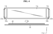
FIGS. 4 and5 are diagrams showing the distribution of thermally conductive resin interposed between an upper surface of a bottom plate and a bottom of a cell stack according to an embodiment of the present disclosure. -
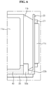
FIG. 6 is an enlarged view of section A ofFIG. 5 . -
FIG. 7 is a schematic plan view of an edge region ofFIG. 5 when viewed from the top. -
FIG. 8 is a schematic diagram showing the main components of a battery module using a secondary battery with a partially cut cell terrace according to another embodiment of the present disclosure. -
FIG. 9 is an enlarged diagram showing the cell terrace of the secondary battery ofFIG. 8 and its variation. -
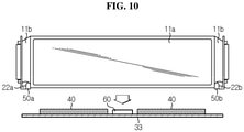
FIGS. 10 and11 are diagrams showing the distribution of thermally conductive resin interposed between an upper surface of a bottom plate and a bottom of a cell stack according to another embodiment of the present disclosure. -
FIG. 12 is an enlarged view of section B ofFIG. 11 . - Hereinafter, the preferred embodiments of the present disclosure will be described in detail with reference to the accompanying drawings. Prior to the description, it should be understood that the terms or words used in the specification and the appended claims should not be construed as being limited to general and dictionary meanings, but rather interpreted based on the meanings and concepts corresponding to the technical aspects of the present disclosure on the basis of the principle that the inventor is allowed to define the terms appropriately for the best explanation. Therefore, the embodiments described herein and illustrations shown in the drawings are just some preferred embodiment of the present disclosure, but are not intended to fully describe the technical aspects of the present disclosure, so it should be understood that a variety of other equivalents and modifications could have been made thereto at the time that the application was filed.
-
FIG. 1 is a schematic perspective view of a battery module according to an embodiment of the present disclosure,FIG. 2 is a diagram showing a cooling configuration of the battery module according to an embodiment of the present disclosure, andFIG. 3 is a diagram showing a cell stack, a thermally conductive resin provided on an upper surface of a bottom plate and a fence member provided in a busbar frame according to an embodiment of the present disclosure. - Referring to
FIGS. 1 to 3 , the battery module according to the present disclosure includes acell stack 10, abusbar frame module housing 30, a thermallyconductive resin 40 and afence member - The
cell stack 10 is an assembly ofsecondary batteries 11, and thesecondary batteries 11 are pouch-type secondary batteries. The pouch-typesecondary batteries 11 may be arranged in thecell stack 10 in the left-right directions (±Y) upright in the up-down directions (±Z axis). - The pouch-type
secondary battery 11 may include an electrode assembly, an electrolyte and a pouch case to package them. - The electrode assembly may include at least one positive electrode plate and at least one negative electrode plate with a separator interposed therebetween. The electrode assembly is well known in the art, and its detailed description will be omitted.
- The pouch case may include an outer insulating layer, a metal layer and an inner adhesive layer. In particular, the pouch case may include a metal thin film, for example, an aluminum thin film, to protect the internal components such as the electrode assembly and the electrolyte, improve the electrochemical properties of the electrode assembly and the electrolyte and enhance heat dissipation. The aluminum thin film may be interposed between the insulating layer formed from an insulating material and the inner adhesive layer to ensure electrical insulation with the internal components of the
secondary battery 11 such as the electrode assembly and the electrolyte or other components outside thesecondary battery 11. - In addition, the pouch case may include a left pouch sheet and a right pouch sheet, and at least one of the left pouch sheet or the right pouch sheet may have a recessed inner space to form a receiving portion. In addition, the electrode assembly may be received in the receiving portion of the pouch. A sealing part is provided on the outer circumferential surfaces of the left pouch sheet and the right pouch sheet, and the inner adhesive layer of the sealing part may be welded to air-tightly seal the receiving portion in which the electrode assembly is received.
- Meanwhile, each electrode plate of the electrode assembly has an electrode tab, and at least one electrode tab may be connected to the
electrode lead 11c. In addition, theelectrode lead 11c, which is exposed to the outside of the pouch case between the sealing part of the left pouch sheet and the sealing part of the right pouch sheet, may function as an electrode terminal of thesecondary battery 11. - Hereinafter, the receiving portion in which the electrode assembly is received in the pouch-type
secondary battery 11, that is, part of the electrode assembly surrounded by the pouch case is referred to as acell body 11a, and the sealing part of the pouch case is referred to as acell terrace 11b. - The
busbar frame first busbar frame 20a mounted on the front side of thecell stack 10 and asecond busbar frame 20b mounted on the rear side of thecell stack 10. The busbar frames 20a and 20b are provided in the shape of a plate having an area that is large enough to cover the front or rear side of thecell stack 10, andslots 23 are formed in the left-right directions on the surface of the plate into which the electrode leads 11c of thesecondary battery 11 are inserted and pass through in the front-rear directions. - In addition, a plurality of
busbars 21 provided in the form of a metal plate may be provided in a predetermined pattern on the front surface of the busbar frames 20a and 20b. For example, the positive electrode leads of two or moresecondary batteries 11 are held together, drawn out of the busbar frames 20a and 20b frontwards through theslots 23, bent at the ends, placed in contact with thebusbars 21 in parallel, and welded together. Likewise, the negative electrode leads of two or more othersecondary batteries 11 are welded to thesame busbar 21. In this way, all thesecondary batteries 11 of thecell stack 10 may be electrically connected in series and in parallel. - In addition, the busbar frames 20a and 20b according to the present disclosure have
lower end portions bottom plate 33. That is, thelower end portions cell body 11a when the busbar frames 20a and 20b and thecell stack 10 are connected, and when thecell stack 10 is placed on the upper surface of thebottom plate 33, thelower end portions bottom plate 33. Although described later, thefence member lower end portions - The
module housing 30 is the component that forms the external shape of the battery module, and may include atop plate 31 that covers the top of thecell stack 10, a pair ofside plates 32 that cover the left and right sides of thecell stack 10, abottom plate 33 that supports thecell stack 10 below thecell stack 10, and amodule front cover 34 and a modulerear cover 35 to prevent thebusbars 21 of the busbar frames 20a and 20b from being exposed to the outside. - The
module housing 30 may serve to protect thecell stack 10 and the busbar frames 20a and 20b from external impacts. Accordingly, themodule housing 30 may be made of metal such as steel to ensure strength. Themodule housing 30 is not necessarily limited to metal, and may be made of any material having strength. - In particular, as shown in
FIG. 2 , in the battery module according to the present disclosure, at least thebottom plate 33 of themodule housing 30 may be made of a thermally conductive material for heat dissipation of the battery module by the contact of theheat sink 100 with the lower surface of thebottom plate 33 of themodule housing 30. When theheat sink 100 is disposed on the lower surface of thebottom plate 33, a thermal interface material 200 (TIM) may be used between the structures to reduce a difference in surface roughness between the structures and lower the thermal contact resistance. - Referring to
FIG. 3 , the thermallyconductive resin 40 having adhesive and thermoplastic properties may be applied to the upper surface of thebottom plate 33. Thecell stack 10 includes the pouch-typesecondary batteries 11 stacked and arranged in the left-right directions (± Y axis), and the lower end portion of each pouch-typesecondary battery 11 may be placed on the upper surface of thebottom plate 33. In this instance, the thermallyconductive resin 40 may be interposed between the lower end portion of the pouch-typesecondary batteries 11 and the upper surface of thebottom plate 33. That is, the thermallyconductive resin 40 may be applied to the upper surface of thebottom plate 33, and the pouch-typesecondary batteries 11 and thebottom plate 33 may be adhered and fixed to each other through the thermallyconductive resin 40. - According to this configuration of the present disclosure, the pouch-type
secondary batteries 11 may be fixed to thebottom plate 33 through the thermallyconductive resin 40 in a simple manner, and the battery module does not need a fastener such as a bolt or a cartridge to fix the pouch-typesecondary batteries 11. Thus, according to this aspect of the present disclosure, it is possible to simplify the structure and assembling of the battery module, and reduce the number of components. - In addition, it is possible to decrease the distance between the pouch-type
secondary batteries 11 and thebottom plate 33 and reduce the number of contacts between the components, thereby effectively transferring heat generated from the pouch-typesecondary batteries 11 to thebottom plate 33. Moreover, it is possible to eliminate an air layer from a space between the pouch-typesecondary batteries 11 and thebottom plate 33 or reduce the air layer, thereby preventing a decrease in heat transfer due to the air layer. - The thermally
conductive resin 40 may include different types of thermally conductive adhesives, and the battery module according to an embodiment of the present disclosure may use different types of organic and/or inorganic thermally conductive adhesives, for example, thermally conductive epoxy adhesives, thermally conductive silicon adhesives and thermally conductive urethane adhesives. - The thermally
conductive resin 40 has higher thermal conductivity than general adhesives, so it is possible to further increase the heat transfer amount and the heat transfer rate between the pouch-typesecondary batteries 11 and thebottom plate 33. Accordingly, it is possible to further improve the heat dissipation performance of thesecondary batteries 11 through thebottom plate 33, thereby further improving the cooling performance of the battery module. - In particular, the battery module according to the present disclosure includes the
fence member bottom plate 33. Thefence member cell stack 10 in the widthwise direction (±Y axis), and a greater height than the thickness of the thermallyconductive resin 40 applied to the upper surface of thebottom plate 33. - The
fence member conductive resin 40 along the front-rear direction of thebottom plate 33 on the upper surface of thebottom plate 33 to prevent the thermallyconductive resin 40 from leaking out in the front-rear directions when placing thecell stack 10 on thebottom plate 33. - More specifically, referring to
FIGS. 3 to 5 , thefence member first fence member 50a provided at the lower end portion of thefirst busbar frame 20a, and asecond fence member 50b provided at the lower end portion of theframe 20b. - The
first fence member 50a and thesecond fence member 50b may be, for example, a memory foam or a rubber pad to absorb impacts, and may be attached to and detached from the ends of thelower end portions first fence member 50a and thesecond fence member 50b may be integrally formed with the busbar frames 20a and 20b, respectively. - In addition, the
first fence member 50a and thesecond fence member 50b may be disposed outside of the lower end portion of thecell body 11a in the front-rear direction (X-axis direction) of the battery module, that is, the lower end portion region of thecell terrace 11b. - In this case, the
fence members cell terrace 11b. Accordingly, thefence members insertion groove 52 in which the lower end portion of thecell terrace 11b is inserted in the up-down directions to avoid contact between thecell terraces 11b. - The
insertion groove 52 of thefence members secondary batteries 11. Each of thecell terraces 11b (seeFIG. 7 ) may extend while being bent at a predetermined angle with respect to the X-axis to hold the electrode leads 11c together and bring them into contact with thebusbar 21. Theinsertion grooves 52 may be formed by partially cutting the bodies of thefence members cell terraces 11b. - The thermally
conductive resin 40 may spread out due to the weight of thecell stack 10 when placing thecell stack 10 on thebottom plate 33, although to different extents depending on the viscosity. Although not shown, the movement of the thermallyconductive resin 40 in the left-right directions (±Y axis) may be may be blocked and restricted by theside plate 32 of themodule housing 30. However, in case there are nofence members conductive resin 40 moves in the front-rear direction (±X axis) away from thecell body 11a of thesecondary batteries 11, the adhesion and fixation between thecell stack 10 and thebottom plate 33 may be weakened, and further, thecell terrace 11b or the busbar frames 20a and 20b may be adversely affected. On the other hand, when the thermallyconductive resin 40 is applied in a smaller amount to prevent the thermallyconductive resin 40 from spreading too wide due to the weight of thecell stack 10, some of the thermallyconductive resin 40 may not contact the bottom of thecell body 11a, and in this case, thecell stack 10 may be poorly fixed and the thermal conductivity may be reduced. - Accordingly, taking into account the above situation, in this embodiment, as shown in
FIG. 4 , the thermallyconductive resin 40 is applied to the upper surface of thebottom plate 33 over an area which is approximately equal to or slightly smaller than the area of the lower end portion of thecell body 11a of the entiresecondary battery 11, so even if the thermallyconductive resin 40 moves in the front-rear direction (±X-axis direction) when placing thecell stack 10, the thermallyconductive resin 40 is blocked by thefirst fence member 50a and thesecond fence member 50b as shown inFIG. 5 , thereby preventing the thermallyconductive resin 40 from leaking out of thecell body 11a. - That is, according to this configuration of the present disclosure, even if the thermally
conductive resin 40 moves in the front-rear directions due to the weight of thecell stack 10 when placing thecell stack 10 on the upper surface of thebottom plate 33, the leakage of the thermallyconductive resin 40 out of thecell body 11a is prevented by thefirst fence member 50a and thesecond fence member 50b. Accordingly, as shown inFIG. 6 , the thermallyconductive resin 40 is wrapped around the end of thecell body 11a along thefence members conductive resin 40 completely covers the entire bottom of thecell body 11a, thereby increasing the amount of heat transfer between thesecondary batteries 11, the thermallyconductive resin 40 and thebottom plate 33, resulting in further improved cooling performance. In particular, higher temperature heat at the end of thecell body 11a may be effectively transferred to thebottom plate 33, thereby reducing a difference in temperature at each area of thesecondary batteries 11, resulting in improved life and performance of thesecondary batteries 11. - Subsequently, another embodiment of the present disclosure will be described with reference to the following drawings.
-
FIG. 8 is a schematic diagram showing the main components of the battery module using thesecondary battery 11 with the partially cutcell terrace 11b according to another embodiment of the present disclosure, andFIG. 9 is a diagram showing thecell terrace 11b of thesecondary battery 11 ofFIG 8 and its variation. - The same reference numerals as those in the previous drawings denote the same elements, and redundant descriptions will be omitted herein, and differences from the above-described embodiments will be mainly described.
- In the above-described embodiment, the
insertion groove 52 is formed in thefence members cell terrace 11b and thefence members insertion groove 52, as shown inFIG. 8 , the lower end portion of thecell terrace 11b is cut into a predetermined shape to prevent the contact with the upper part of thefence members cell terrace 11b may be cut to conform to the shape of thefence members FIG. 9 or in an angled shape as shown in (b) ofFIG. 9 . - According to this embodiment, when the
cell stack 10 is placed on thebottom plate 33, it is necessary to individually insert the lower end portions of thecell terraces 11b into theinsertion grooves 52 of thefence members fence members cell terrace 11b, but these disadvantages are all solved, and it is possible to connect thecell stack 10 and the busbar frames 20a and 20b more easily and faster than the above-described embodiment. In addition, theinsertion grooves 52 may not be formed in thefence members fence members - Meanwhile, in a similar way to this embodiment, the lower end portion of the
cell terrace 11b may be bent or folded to avoid interference with thefence members - Subsequently, another embodiment of the present disclosure will be described with reference to the following drawings.
-
FIGS. 10 and11 are diagrams showing the distribution of the thermallyconductive resin 40 interposed between the upper surface of thebottom plate 33 and the bottom of thecell stack 10 according to another embodiment of the present disclosure, andFIG. 12 is an enlarged view of section B ofFIG. 11 . - The same reference numerals as those in the previous drawings denote the same elements, and redundant descriptions of the same elements will be omitted herein, and differences from the above-described embodiments will be mainly described.
- The battery module according to another embodiment of the present disclosure further includes a
resin isolating member 60. - The
resin isolating member 60 may protrude from the surface of thebottom plate 33 and extend in the left-right direction (±Y axis) of thebottom plate 33. Theresin isolating member 60 may be provided in the form of a pad that is similar to the above-describedfence members bottom plate 33. In this embodiment, the thermallyconductive resin 40 may be applied between theresin isolating member 60 and thefirst fence member 50a, and between theresin isolating member 60 and thesecond fence member 50b. - According to the configuration of this embodiment, the
resin isolating member 60 supports the center of thecell body 11a to induce the uniform distribution of the thermallyconductive resin 40 in the front-rear directions (±X axis) along the bottom of thecell body 11a. In particular, due to the characteristics of the pouch-typesecondary batteries 11, the temperature at the edge of thecell body 11a is higher than the temperature at the center of thecell body 11a, so when theresin isolating member 60 is disposed at the center of thecell body 11a, it is possible to block the heat transfer from the edge of thecell body 11a to the center of thecell body 11a, thereby reducing a difference in temperature at each area of thesecondary batteries 11. In addition, it is possible to reduce the amount of the thermallyconductive resin 40 as much as the space occupied by theresin isolating member 60, thereby achieving cost savings. - Meanwhile, a battery pack according to the present disclosure may include one or more battery modules according to the present disclosure. In addition to the battery module, the battery pack according to the present disclosure may further include a pack case to receive the battery module, different types of devices to control the charge/discharge of the battery module, for example, a battery management system (BMS), a current sensor, a fuse, etc.
- The battery module according to the present disclosure may be applied to vehicles such as electric vehicles or hybrid electric vehicles. That is, the vehicle according to the present disclosure may include the battery module according to the present disclosure. In particular, in the case of vehicles that obtain driving power from batteries, such as electric vehicles, the cooling performance of the battery module is very important. Accordingly, when the battery module according to the present disclosure is applied to vehicles, it is possible to provide stable and safe battery modules with effective cooling performance.
- While the present disclosure has been hereinabove described with regard to a limited number of embodiments and drawings, the present disclosure is not limited thereto and it is obvious to those skilled in the art that various modifications and changes may be made thereto within the technical aspects of the present disclosure and the equivalent scope of the appended claims.
- It should be noted that the terms indicating directions as used herein such as up, down, left and right are used for convenience of description only, and it is obvious to those skilled in the art that the term may change depending on the position of the stated element or an observer.
Claims (11)
- A battery module comprising:a cell stack including a plurality of pouch-type secondary batteries standing upright in up-down directions and arranged in left-right directions;a busbar frame mounted on front and rear sides of the cell stack;a bottom plate made of a thermally conductive material, the bottom plate supporting the cell stack below the cell stack;a thermally conductive resin applied on an upper surface of the bottom plate before the cell stack is placed on the bottom plate ; anda fence member disposed in front-rear directions of the bottom plate outside of the thermally conductive resin to prevent the thermally conductive resin from leaking out in front-rear directions when placing the cell stack on the bottom plate,wherein the busbar frame has a lower end portion bent and extended in an inward direction of the upper surface of the bottom plate, andthe fence member is provided at an end of the lower end portion of the busbar frame and placed on the upper surface of the bottom plate.
- The battery module according to claim 1, wherein the pouch-type secondary batteries includes:a cell body in which an electrode assembly is surrounded by a pouch case; anda cell terrace formed outside of the cell body by heat fusion of the pouch case, andthe fence member is disposed outside of the cell body.
- The battery module according to claim 2, wherein the fence member has an insertion groove in which part of the cell terrace is inserted in the up-down directions.
- The battery module according to claim 1, wherein the fence member has a length corresponding to a widthwise direction length of the cell stack, and a greater height than a thickness of the thermally conductive resin applied to the upper surface of the bottom plate.
- The battery module according to claim 1, wherein the thermally conductive resin has adhesive and thermoplastic properties.
- The battery module according to claim 1, wherein the fence member is provided in a form of a foam or a pad made of rubber and attached to the lower end portion of the busbar frame.
- The battery module according to claim 2, wherein the cell terrace is partially cut to prevent contact with an upper part of the fence member.
- The battery module according to claim 2, wherein the busbar frame includes a first busbar frame mounted on a front side of the cell stack, and a second busbar frame mounted on a rear side of the cell stack, and
the fence member includes a first fence member provided at the lower end portion of the first busbar frame, and a second fence member provided at the lower end portion of the second busbar frame. - The battery module according to claim 8, further comprising:a resin isolating member disposed between the first fence member and the second fence member on the upper surface of the bottom plate, the resin isolating member protruding from a surface of the bottom plate and extending in the left-right directions of the bottom plate, andthe thermally conductive resin is applied between the resin isolating member and the first fence member, and between the resin isolating member and the second fence member.
- A battery pack comprising the battery module according to any one of claims 1 to 9.
- An electric vehicle comprising the battery module according to any one of claims 1 to 9.
Applications Claiming Priority (2)
| Application Number | Priority Date | Filing Date | Title |
|---|---|---|---|
| KR1020190153704A KR102757441B1 (en) | 2019-11-26 | 2019-11-26 | Battery module |
| PCT/KR2020/007929 WO2021107305A1 (en) | 2019-11-26 | 2020-06-18 | Battery module |
Publications (3)
| Publication Number | Publication Date |
|---|---|
| EP3958377A1 true EP3958377A1 (en) | 2022-02-23 |
| EP3958377A4 EP3958377A4 (en) | 2022-08-10 |
| EP3958377B1 EP3958377B1 (en) | 2025-04-30 |
Family
ID=76129694
Family Applications (1)
| Application Number | Title | Priority Date | Filing Date |
|---|---|---|---|
| EP20892480.3A Active EP3958377B1 (en) | 2019-11-26 | 2020-06-18 | BATTERY MODULE |
Country Status (8)
| Country | Link |
|---|---|
| US (1) | US12418061B2 (en) |
| EP (1) | EP3958377B1 (en) |
| JP (1) | JP7106008B2 (en) |
| KR (1) | KR102757441B1 (en) |
| CN (1) | CN113678302B (en) |
| ES (1) | ES3030110T3 (en) |
| HU (1) | HUE071479T2 (en) |
| WO (1) | WO2021107305A1 (en) |
Families Citing this family (9)
| Publication number | Priority date | Publication date | Assignee | Title |
|---|---|---|---|---|
| KR102937131B1 (en) * | 2020-08-14 | 2026-03-09 | 주식회사 엘지에너지솔루션 | Battery module and battery pack including the same |
| JP7480754B2 (en) * | 2021-07-19 | 2024-05-10 | トヨタ自動車株式会社 | Power storage device |
| KR102928820B1 (en) * | 2021-08-20 | 2026-02-19 | 주식회사 엘지에너지솔루션 | Battery module and battery pack including the same |
| KR20230033903A (en) * | 2021-09-02 | 2023-03-09 | 주식회사 엘지에너지솔루션 | Battery module and battery pack including the same |
| KR20230037161A (en) * | 2021-09-09 | 2023-03-16 | 주식회사 엘지에너지솔루션 | Battery module and battery pack including the same |
| KR102938554B1 (en) * | 2021-10-05 | 2026-03-13 | 주식회사 엘지에너지솔루션 | Secondary battery Tray |
| KR20240135101A (en) * | 2023-03-03 | 2024-09-10 | 주식회사 엘지에너지솔루션 | Battery pack |
| JP2025034809A (en) * | 2023-08-31 | 2025-03-13 | 株式会社Aescジャパン | Battery Module |
| US20250210786A1 (en) * | 2023-12-22 | 2025-06-26 | Aesc Japan Ltd. | Battery pack and electric vehicle |
Family Cites Families (25)
| Publication number | Priority date | Publication date | Assignee | Title |
|---|---|---|---|---|
| DE102008061277A1 (en) * | 2008-12-10 | 2010-06-24 | Conti Temic Microelectronic Gmbh | energy storage |
| KR101392799B1 (en) | 2012-06-07 | 2014-05-14 | 주식회사 엘지화학 | Battery Module Having Structure of Improved Stability and High Cooling Efficiency |
| KR102050289B1 (en) * | 2012-10-24 | 2020-01-08 | 에스케이이노베이션 주식회사 | Battery module |
| KR20150105045A (en) | 2014-03-07 | 2015-09-16 | 현대모비스 주식회사 | Heat-pipe assembly having heating and cooling function, battery module for eco-friendly vehicle using of the heat-pipe assembly, method for manufacturing of the heat-pipe assembly, method for manufacturing of the battery module, and method for operating of the battery module |
| JP6267571B2 (en) * | 2014-04-23 | 2018-01-24 | 日立建機株式会社 | Cooling structure for work machine and power storage device mounted on the work machine |
| KR101863703B1 (en) | 2014-10-20 | 2018-06-01 | 주식회사 엘지화학 | Pouch-type secondary battery and method for manufacturing the same |
| KR101865995B1 (en) | 2015-03-27 | 2018-06-08 | 주식회사 엘지화학 | Battery module |
| KR101809208B1 (en) * | 2015-06-16 | 2017-12-14 | 주식회사 엘지화학 | Secondary battery and method for fabricating the same |
| JP6620478B2 (en) | 2015-09-14 | 2019-12-18 | 株式会社豊田自動織機 | Battery pack and battery module |
| KR101943542B1 (en) | 2015-09-21 | 2019-01-29 | 주식회사 엘지화학 | Battery module and battery pack comprising the same |
| KR102050530B1 (en) * | 2015-09-24 | 2019-12-02 | 주식회사 엘지화학 | Battery Module |
| JP6558198B2 (en) | 2015-10-15 | 2019-08-14 | 株式会社豊田自動織機 | Battery module |
| JP6620583B2 (en) | 2016-02-09 | 2019-12-18 | 株式会社豊田自動織機 | Storage module manufacturing method and storage module |
| KR102034208B1 (en) | 2016-03-03 | 2019-10-18 | 주식회사 엘지화학 | Battery module, battery pack the battery module and vehicle comprising the battery pack |
| KR102119183B1 (en) * | 2016-08-18 | 2020-06-04 | 주식회사 엘지화학 | Battery module |
| KR20180092065A (en) | 2017-02-08 | 2018-08-17 | 에이치엘그린파워 주식회사 | Battery module and Method for assembling the same |
| CN207183361U (en) * | 2017-08-31 | 2018-04-03 | 宁德时代新能源科技股份有限公司 | Frame and battery module |
| CN109428020B (en) | 2017-08-31 | 2024-04-16 | 宁德时代新能源科技股份有限公司 | Frame and battery module |
| JP6922683B2 (en) * | 2017-11-17 | 2021-08-18 | トヨタ自動車株式会社 | Battery pack, battery pack manufacturing method and intervening members |
| CN109994798B (en) * | 2017-12-26 | 2025-08-15 | Sk新能源株式会社 | Battery module and method for manufacturing same |
| DE102018133391A1 (en) | 2017-12-26 | 2019-06-27 | Sk Innovation Co., Ltd. | Battery module and manufacturing method thereof |
| KR102273195B1 (en) | 2017-12-27 | 2021-07-05 | 주식회사 엘지에너지솔루션 | Battery module with improved cooling structure |
| JP7163615B2 (en) | 2018-05-09 | 2022-11-01 | 株式会社Gsユアサ | power storage device |
| JP6898889B2 (en) * | 2018-07-06 | 2021-07-07 | 矢崎総業株式会社 | Batteries |
| CN110364655A (en) | 2019-07-17 | 2019-10-22 | 芜湖天量电池系统有限公司 | A kind of power battery pack arrangement and its packaging technology |
-
2019
- 2019-11-26 KR KR1020190153704A patent/KR102757441B1/en active Active
-
2020
- 2020-06-18 US US17/428,869 patent/US12418061B2/en active Active
- 2020-06-18 EP EP20892480.3A patent/EP3958377B1/en active Active
- 2020-06-18 ES ES20892480T patent/ES3030110T3/en active Active
- 2020-06-18 JP JP2021531214A patent/JP7106008B2/en active Active
- 2020-06-18 HU HUE20892480A patent/HUE071479T2/en unknown
- 2020-06-18 WO PCT/KR2020/007929 patent/WO2021107305A1/en not_active Ceased
- 2020-06-18 CN CN202080008774.2A patent/CN113678302B/en active Active
Also Published As
| Publication number | Publication date |
|---|---|
| CN113678302A (en) | 2021-11-19 |
| WO2021107305A1 (en) | 2021-06-03 |
| US12418061B2 (en) | 2025-09-16 |
| HUE071479T2 (en) | 2025-08-28 |
| JP2022515326A (en) | 2022-02-18 |
| EP3958377A4 (en) | 2022-08-10 |
| JP7106008B2 (en) | 2022-07-25 |
| KR102757441B1 (en) | 2025-01-17 |
| EP3958377B1 (en) | 2025-04-30 |
| CN113678302B (en) | 2024-11-12 |
| KR20210064935A (en) | 2021-06-03 |
| ES3030110T3 (en) | 2025-06-26 |
| US20220109199A1 (en) | 2022-04-07 |
Similar Documents
| Publication | Publication Date | Title |
|---|---|---|
| EP3958377B1 (en) | BATTERY MODULE | |
| KR102382382B1 (en) | Battery Module Having Heat-Shrinkable Tube | |
| US12548815B2 (en) | Battery module | |
| KR102879667B1 (en) | Battery module and battery pack including the same | |
| EP4300686B1 (en) | Battery module and battery pack including the same | |
| KR20180023699A (en) | Battery module | |
| KR102772825B1 (en) | Battery pack and device including the same | |
| KR102762546B1 (en) | Battery module | |
| KR102917125B1 (en) | Battery module and battery pack including the same | |
| US20240387900A1 (en) | Battery module and battery pack including the same | |
| KR102930264B1 (en) | Battery pack and device including the same | |
| KR20210150843A (en) | Battery module and battery pack including the same | |
| US12347883B2 (en) | Battery module and battery including the same | |
| EP4181275B1 (en) | Battery module and battery pack including same | |
| KR102892940B1 (en) | Battery module and battery pack including the same | |
| KR102949002B1 (en) | Battery module and battery pack including the same | |
| KR20210133538A (en) | Battery pack and device including the same | |
| KR20210133543A (en) | Battery module and battery pack including the same | |
| EP4738541A1 (en) | Battery module, battery pack and vehicle including same | |
| KR20220041426A (en) | Battery module and battery pack including the same |
Legal Events
| Date | Code | Title | Description |
|---|---|---|---|
| STAA | Information on the status of an ep patent application or granted ep patent |
Free format text: STATUS: THE INTERNATIONAL PUBLICATION HAS BEEN MADE |
|
| PUAI | Public reference made under article 153(3) epc to a published international application that has entered the european phase |
Free format text: ORIGINAL CODE: 0009012 |
|
| STAA | Information on the status of an ep patent application or granted ep patent |
Free format text: STATUS: REQUEST FOR EXAMINATION WAS MADE |
|
| 17P | Request for examination filed |
Effective date: 20211118 |
|
| AK | Designated contracting states |
Kind code of ref document: A1 Designated state(s): AL AT BE BG CH CY CZ DE DK EE ES FI FR GB GR HR HU IE IS IT LI LT LU LV MC MK MT NL NO PL PT RO RS SE SI SK SM TR |
|
| RAP3 | Party data changed (applicant data changed or rights of an application transferred) |
Owner name: LG ENERGY SOLUTION, LTD. |
|
| REG | Reference to a national code |
Ref country code: DE Ref legal event code: R079 Free format text: PREVIOUS MAIN CLASS: H01M0010655400 Ipc: H01M0050211000 Ref document number: 602020050622 Country of ref document: DE |
|
| A4 | Supplementary search report drawn up and despatched |
Effective date: 20220712 |
|
| RIC1 | Information provided on ipc code assigned before grant |
Ipc: H01M 50/105 20210101ALI20220706BHEP Ipc: H01M 10/625 20140101ALI20220706BHEP Ipc: H01M 10/647 20140101ALI20220706BHEP Ipc: H01M 10/653 20140101ALI20220706BHEP Ipc: H01M 10/6554 20140101ALI20220706BHEP Ipc: H01M 50/507 20210101ALI20220706BHEP Ipc: H01M 50/211 20210101AFI20220706BHEP |
|
| DAV | Request for validation of the european patent (deleted) | ||
| DAX | Request for extension of the european patent (deleted) | ||
| GRAP | Despatch of communication of intention to grant a patent |
Free format text: ORIGINAL CODE: EPIDOSNIGR1 |
|
| STAA | Information on the status of an ep patent application or granted ep patent |
Free format text: STATUS: GRANT OF PATENT IS INTENDED |
|
| RIC1 | Information provided on ipc code assigned before grant |
Ipc: H01M 50/105 20210101ALI20241127BHEP Ipc: H01M 10/625 20140101ALI20241127BHEP Ipc: H01M 10/647 20140101ALI20241127BHEP Ipc: H01M 10/653 20140101ALI20241127BHEP Ipc: H01M 10/6554 20140101ALI20241127BHEP Ipc: H01M 50/507 20210101ALI20241127BHEP Ipc: H01M 50/211 20210101AFI20241127BHEP |
|
| INTG | Intention to grant announced |
Effective date: 20241209 |
|
| GRAJ | Information related to disapproval of communication of intention to grant by the applicant or resumption of examination proceedings by the epo deleted |
Free format text: ORIGINAL CODE: EPIDOSDIGR1 |
|
| STAA | Information on the status of an ep patent application or granted ep patent |
Free format text: STATUS: REQUEST FOR EXAMINATION WAS MADE |
|
| P01 | Opt-out of the competence of the unified patent court (upc) registered |
Free format text: CASE NUMBER: APP_589/2025 Effective date: 20250107 |
|
| GRAP | Despatch of communication of intention to grant a patent |
Free format text: ORIGINAL CODE: EPIDOSNIGR1 |
|
| STAA | Information on the status of an ep patent application or granted ep patent |
Free format text: STATUS: GRANT OF PATENT IS INTENDED |
|
| INTC | Intention to grant announced (deleted) | ||
| GRAS | Grant fee paid |
Free format text: ORIGINAL CODE: EPIDOSNIGR3 |
|
| INTG | Intention to grant announced |
Effective date: 20250218 |
|
| GRAA | (expected) grant |
Free format text: ORIGINAL CODE: 0009210 |
|
| STAA | Information on the status of an ep patent application or granted ep patent |
Free format text: STATUS: THE PATENT HAS BEEN GRANTED |
|
| AK | Designated contracting states |
Kind code of ref document: B1 Designated state(s): AL AT BE BG CH CY CZ DE DK EE ES FI FR GB GR HR HU IE IS IT LI LT LU LV MC MK MT NL NO PL PT RO RS SE SI SK SM TR |
|
| REG | Reference to a national code |
Ref country code: CH Ref legal event code: EP Ref country code: GB Ref legal event code: FG4D |
|
| REG | Reference to a national code |
Ref country code: DE Ref legal event code: R096 Ref document number: 602020050622 Country of ref document: DE |
|
| REG | Reference to a national code |
Ref country code: IE Ref legal event code: FG4D |
|
| REG | Reference to a national code |
Ref country code: ES Ref legal event code: FG2A Ref document number: 3030110 Country of ref document: ES Kind code of ref document: T3 Effective date: 20250626 |
|
| PGFP | Annual fee paid to national office [announced via postgrant information from national office to epo] |
Ref country code: DE Payment date: 20250520 Year of fee payment: 6 |
|
| PGFP | Annual fee paid to national office [announced via postgrant information from national office to epo] |
Ref country code: GB Payment date: 20250520 Year of fee payment: 6 |
|
| PGFP | Annual fee paid to national office [announced via postgrant information from national office to epo] |
Ref country code: BE Payment date: 20250520 Year of fee payment: 6 |
|
| PGFP | Annual fee paid to national office [announced via postgrant information from national office to epo] |
Ref country code: FR Payment date: 20250521 Year of fee payment: 6 |
|
| PGFP | Annual fee paid to national office [announced via postgrant information from national office to epo] |
Ref country code: HU Payment date: 20250721 Year of fee payment: 6 |
|
| REG | Reference to a national code |
Ref country code: HU Ref legal event code: AG4A Ref document number: E071479 Country of ref document: HU |
|
| REG | Reference to a national code |
Ref country code: NL Ref legal event code: MP Effective date: 20250430 |
|
| REG | Reference to a national code |
Ref country code: AT Ref legal event code: MK05 Ref document number: 1790965 Country of ref document: AT Kind code of ref document: T Effective date: 20250430 |
|
| PG25 | Lapsed in a contracting state [announced via postgrant information from national office to epo] |
Ref country code: FI Free format text: LAPSE BECAUSE OF FAILURE TO SUBMIT A TRANSLATION OF THE DESCRIPTION OR TO PAY THE FEE WITHIN THE PRESCRIBED TIME-LIMIT Effective date: 20250430 Ref country code: PT Free format text: LAPSE BECAUSE OF FAILURE TO SUBMIT A TRANSLATION OF THE DESCRIPTION OR TO PAY THE FEE WITHIN THE PRESCRIBED TIME-LIMIT Effective date: 20250901 |
|
| PGFP | Annual fee paid to national office [announced via postgrant information from national office to epo] |
Ref country code: ES Payment date: 20250714 Year of fee payment: 6 |
|
| REG | Reference to a national code |
Ref country code: LT Ref legal event code: MG9D |
|
| PG25 | Lapsed in a contracting state [announced via postgrant information from national office to epo] |
Ref country code: GR Free format text: LAPSE BECAUSE OF FAILURE TO SUBMIT A TRANSLATION OF THE DESCRIPTION OR TO PAY THE FEE WITHIN THE PRESCRIBED TIME-LIMIT Effective date: 20250731 Ref country code: NO Free format text: LAPSE BECAUSE OF FAILURE TO SUBMIT A TRANSLATION OF THE DESCRIPTION OR TO PAY THE FEE WITHIN THE PRESCRIBED TIME-LIMIT Effective date: 20250730 |
|
| PG25 | Lapsed in a contracting state [announced via postgrant information from national office to epo] |
Ref country code: NL Free format text: LAPSE BECAUSE OF FAILURE TO SUBMIT A TRANSLATION OF THE DESCRIPTION OR TO PAY THE FEE WITHIN THE PRESCRIBED TIME-LIMIT Effective date: 20250430 Ref country code: PL Free format text: LAPSE BECAUSE OF FAILURE TO SUBMIT A TRANSLATION OF THE DESCRIPTION OR TO PAY THE FEE WITHIN THE PRESCRIBED TIME-LIMIT Effective date: 20250430 |
|
| PG25 | Lapsed in a contracting state [announced via postgrant information from national office to epo] |
Ref country code: BG Free format text: LAPSE BECAUSE OF FAILURE TO SUBMIT A TRANSLATION OF THE DESCRIPTION OR TO PAY THE FEE WITHIN THE PRESCRIBED TIME-LIMIT Effective date: 20250430 |
|
| PG25 | Lapsed in a contracting state [announced via postgrant information from national office to epo] |
Ref country code: HR Free format text: LAPSE BECAUSE OF FAILURE TO SUBMIT A TRANSLATION OF THE DESCRIPTION OR TO PAY THE FEE WITHIN THE PRESCRIBED TIME-LIMIT Effective date: 20250430 |
|
| PG25 | Lapsed in a contracting state [announced via postgrant information from national office to epo] |
Ref country code: AT Free format text: LAPSE BECAUSE OF FAILURE TO SUBMIT A TRANSLATION OF THE DESCRIPTION OR TO PAY THE FEE WITHIN THE PRESCRIBED TIME-LIMIT Effective date: 20250430 |
|
| PG25 | Lapsed in a contracting state [announced via postgrant information from national office to epo] |
Ref country code: RS Free format text: LAPSE BECAUSE OF FAILURE TO SUBMIT A TRANSLATION OF THE DESCRIPTION OR TO PAY THE FEE WITHIN THE PRESCRIBED TIME-LIMIT Effective date: 20250731 |
|
| PG25 | Lapsed in a contracting state [announced via postgrant information from national office to epo] |
Ref country code: IS Free format text: LAPSE BECAUSE OF FAILURE TO SUBMIT A TRANSLATION OF THE DESCRIPTION OR TO PAY THE FEE WITHIN THE PRESCRIBED TIME-LIMIT Effective date: 20250830 |
|
| PG25 | Lapsed in a contracting state [announced via postgrant information from national office to epo] |
Ref country code: LV Free format text: LAPSE BECAUSE OF FAILURE TO SUBMIT A TRANSLATION OF THE DESCRIPTION OR TO PAY THE FEE WITHIN THE PRESCRIBED TIME-LIMIT Effective date: 20250430 |
|
| PG25 | Lapsed in a contracting state [announced via postgrant information from national office to epo] |
Ref country code: DK Free format text: LAPSE BECAUSE OF FAILURE TO SUBMIT A TRANSLATION OF THE DESCRIPTION OR TO PAY THE FEE WITHIN THE PRESCRIBED TIME-LIMIT Effective date: 20250430 Ref country code: SM Free format text: LAPSE BECAUSE OF FAILURE TO SUBMIT A TRANSLATION OF THE DESCRIPTION OR TO PAY THE FEE WITHIN THE PRESCRIBED TIME-LIMIT Effective date: 20250430 |
|
| PG25 | Lapsed in a contracting state [announced via postgrant information from national office to epo] |
Ref country code: CZ Free format text: LAPSE BECAUSE OF FAILURE TO SUBMIT A TRANSLATION OF THE DESCRIPTION OR TO PAY THE FEE WITHIN THE PRESCRIBED TIME-LIMIT Effective date: 20250430 |
|
| PG25 | Lapsed in a contracting state [announced via postgrant information from national office to epo] |
Ref country code: EE Free format text: LAPSE BECAUSE OF FAILURE TO SUBMIT A TRANSLATION OF THE DESCRIPTION OR TO PAY THE FEE WITHIN THE PRESCRIBED TIME-LIMIT Effective date: 20250430 |
|
| PG25 | Lapsed in a contracting state [announced via postgrant information from national office to epo] |
Ref country code: SK Free format text: LAPSE BECAUSE OF FAILURE TO SUBMIT A TRANSLATION OF THE DESCRIPTION OR TO PAY THE FEE WITHIN THE PRESCRIBED TIME-LIMIT Effective date: 20250430 Ref country code: RO Free format text: LAPSE BECAUSE OF FAILURE TO SUBMIT A TRANSLATION OF THE DESCRIPTION OR TO PAY THE FEE WITHIN THE PRESCRIBED TIME-LIMIT Effective date: 20250430 |
|
| REG | Reference to a national code |
Ref country code: CH Ref legal event code: H13 Free format text: ST27 STATUS EVENT CODE: U-0-0-H10-H13 (AS PROVIDED BY THE NATIONAL OFFICE) Effective date: 20260127 |
|
| PG25 | Lapsed in a contracting state [announced via postgrant information from national office to epo] |
Ref country code: IT Free format text: LAPSE BECAUSE OF FAILURE TO SUBMIT A TRANSLATION OF THE DESCRIPTION OR TO PAY THE FEE WITHIN THE PRESCRIBED TIME-LIMIT Effective date: 20250430 |
|
| PG25 | Lapsed in a contracting state [announced via postgrant information from national office to epo] |
Ref country code: MC Free format text: LAPSE BECAUSE OF FAILURE TO SUBMIT A TRANSLATION OF THE DESCRIPTION OR TO PAY THE FEE WITHIN THE PRESCRIBED TIME-LIMIT Effective date: 20250430 |
|
| REG | Reference to a national code |
Ref country code: DE Ref legal event code: R097 Ref document number: 602020050622 Country of ref document: DE |
|
| PG25 | Lapsed in a contracting state [announced via postgrant information from national office to epo] |
Ref country code: LU Free format text: LAPSE BECAUSE OF NON-PAYMENT OF DUE FEES Effective date: 20250618 |
|
| PLBE | No opposition filed within time limit |
Free format text: ORIGINAL CODE: 0009261 |
|
| STAA | Information on the status of an ep patent application or granted ep patent |
Free format text: STATUS: NO OPPOSITION FILED WITHIN TIME LIMIT |
|
| REG | Reference to a national code |
Ref country code: CH Ref legal event code: L10 Free format text: ST27 STATUS EVENT CODE: U-0-0-L10-L00 (AS PROVIDED BY THE NATIONAL OFFICE) Effective date: 20260311 |
|
| 26N | No opposition filed |
Effective date: 20260202 |
|
| PG25 | Lapsed in a contracting state [announced via postgrant information from national office to epo] |
Ref country code: IE Free format text: LAPSE BECAUSE OF NON-PAYMENT OF DUE FEES Effective date: 20250618 |
|
| PG25 | Lapsed in a contracting state [announced via postgrant information from national office to epo] |
Ref country code: CH Free format text: LAPSE BECAUSE OF NON-PAYMENT OF DUE FEES Effective date: 20250630 |