EP3958372A1 - Energy storage cabinet - Google Patents
Energy storage cabinet Download PDFInfo
- Publication number
- EP3958372A1 EP3958372A1 EP21151035.9A EP21151035A EP3958372A1 EP 3958372 A1 EP3958372 A1 EP 3958372A1 EP 21151035 A EP21151035 A EP 21151035A EP 3958372 A1 EP3958372 A1 EP 3958372A1
- Authority
- EP
- European Patent Office
- Prior art keywords
- battery
- management module
- assembly
- energy storage
- storage cabinet
- Prior art date
- Legal status (The legal status is an assumption and is not a legal conclusion. Google has not performed a legal analysis and makes no representation as to the accuracy of the status listed.)
- Pending
Links
Images






Classifications
-
- H—ELECTRICITY
- H01—ELECTRIC ELEMENTS
- H01M—PROCESSES OR MEANS, e.g. BATTERIES, FOR THE DIRECT CONVERSION OF CHEMICAL ENERGY INTO ELECTRICAL ENERGY
- H01M50/00—Constructional details or processes of manufacture of the non-active parts of electrochemical cells other than fuel cells, e.g. hybrid cells
- H01M50/20—Mountings; Secondary casings or frames; Racks, modules or packs; Suspension devices; Shock absorbers; Transport or carrying devices; Holders
- H01M50/204—Racks, modules or packs for multiple batteries or multiple cells
-
- H—ELECTRICITY
- H01—ELECTRIC ELEMENTS
- H01M—PROCESSES OR MEANS, e.g. BATTERIES, FOR THE DIRECT CONVERSION OF CHEMICAL ENERGY INTO ELECTRICAL ENERGY
- H01M10/00—Secondary cells; Manufacture thereof
- H01M10/42—Methods or arrangements for servicing or maintenance of secondary cells or secondary half-cells
- H01M10/425—Structural combination with electronic components, e.g. electronic circuits integrated to the outside of the casing
- H01M10/4257—Smart batteries, e.g. electronic circuits inside the housing of the cells or batteries
-
- H—ELECTRICITY
- H01—ELECTRIC ELEMENTS
- H01M—PROCESSES OR MEANS, e.g. BATTERIES, FOR THE DIRECT CONVERSION OF CHEMICAL ENERGY INTO ELECTRICAL ENERGY
- H01M10/00—Secondary cells; Manufacture thereof
- H01M10/42—Methods or arrangements for servicing or maintenance of secondary cells or secondary half-cells
- H01M10/425—Structural combination with electronic components, e.g. electronic circuits integrated to the outside of the casing
-
- H—ELECTRICITY
- H01—ELECTRIC ELEMENTS
- H01M—PROCESSES OR MEANS, e.g. BATTERIES, FOR THE DIRECT CONVERSION OF CHEMICAL ENERGY INTO ELECTRICAL ENERGY
- H01M50/00—Constructional details or processes of manufacture of the non-active parts of electrochemical cells other than fuel cells, e.g. hybrid cells
- H01M50/20—Mountings; Secondary casings or frames; Racks, modules or packs; Suspension devices; Shock absorbers; Transport or carrying devices; Holders
- H01M50/233—Mountings; Secondary casings or frames; Racks, modules or packs; Suspension devices; Shock absorbers; Transport or carrying devices; Holders characterised by physical properties of casings or racks, e.g. dimensions
- H01M50/236—Hardness
-
- H—ELECTRICITY
- H01—ELECTRIC ELEMENTS
- H01M—PROCESSES OR MEANS, e.g. BATTERIES, FOR THE DIRECT CONVERSION OF CHEMICAL ENERGY INTO ELECTRICAL ENERGY
- H01M50/00—Constructional details or processes of manufacture of the non-active parts of electrochemical cells other than fuel cells, e.g. hybrid cells
- H01M50/20—Mountings; Secondary casings or frames; Racks, modules or packs; Suspension devices; Shock absorbers; Transport or carrying devices; Holders
- H01M50/244—Secondary casings; Racks; Suspension devices; Carrying devices; Holders characterised by their mounting method
-
- H—ELECTRICITY
- H01—ELECTRIC ELEMENTS
- H01M—PROCESSES OR MEANS, e.g. BATTERIES, FOR THE DIRECT CONVERSION OF CHEMICAL ENERGY INTO ELECTRICAL ENERGY
- H01M50/00—Constructional details or processes of manufacture of the non-active parts of electrochemical cells other than fuel cells, e.g. hybrid cells
- H01M50/20—Mountings; Secondary casings or frames; Racks, modules or packs; Suspension devices; Shock absorbers; Transport or carrying devices; Holders
- H01M50/258—Modular batteries; Casings provided with means for assembling
-
- H—ELECTRICITY
- H01—ELECTRIC ELEMENTS
- H01M—PROCESSES OR MEANS, e.g. BATTERIES, FOR THE DIRECT CONVERSION OF CHEMICAL ENERGY INTO ELECTRICAL ENERGY
- H01M50/00—Constructional details or processes of manufacture of the non-active parts of electrochemical cells other than fuel cells, e.g. hybrid cells
- H01M50/20—Mountings; Secondary casings or frames; Racks, modules or packs; Suspension devices; Shock absorbers; Transport or carrying devices; Holders
- H01M50/262—Mountings; Secondary casings or frames; Racks, modules or packs; Suspension devices; Shock absorbers; Transport or carrying devices; Holders with fastening means, e.g. locks
- H01M50/264—Mountings; Secondary casings or frames; Racks, modules or packs; Suspension devices; Shock absorbers; Transport or carrying devices; Holders with fastening means, e.g. locks for cells or batteries, e.g. straps, tie rods or peripheral frames
-
- H—ELECTRICITY
- H01—ELECTRIC ELEMENTS
- H01M—PROCESSES OR MEANS, e.g. BATTERIES, FOR THE DIRECT CONVERSION OF CHEMICAL ENERGY INTO ELECTRICAL ENERGY
- H01M50/00—Constructional details or processes of manufacture of the non-active parts of electrochemical cells other than fuel cells, e.g. hybrid cells
- H01M50/20—Mountings; Secondary casings or frames; Racks, modules or packs; Suspension devices; Shock absorbers; Transport or carrying devices; Holders
- H01M50/284—Mountings; Secondary casings or frames; Racks, modules or packs; Suspension devices; Shock absorbers; Transport or carrying devices; Holders with incorporated circuit boards, e.g. printed circuit boards [PCB]
-
- H—ELECTRICITY
- H01—ELECTRIC ELEMENTS
- H01M—PROCESSES OR MEANS, e.g. BATTERIES, FOR THE DIRECT CONVERSION OF CHEMICAL ENERGY INTO ELECTRICAL ENERGY
- H01M50/00—Constructional details or processes of manufacture of the non-active parts of electrochemical cells other than fuel cells, e.g. hybrid cells
- H01M50/20—Mountings; Secondary casings or frames; Racks, modules or packs; Suspension devices; Shock absorbers; Transport or carrying devices; Holders
- H01M50/289—Mountings; Secondary casings or frames; Racks, modules or packs; Suspension devices; Shock absorbers; Transport or carrying devices; Holders characterised by spacing elements or positioning means within frames, racks or packs
-
- H—ELECTRICITY
- H01—ELECTRIC ELEMENTS
- H01M—PROCESSES OR MEANS, e.g. BATTERIES, FOR THE DIRECT CONVERSION OF CHEMICAL ENERGY INTO ELECTRICAL ENERGY
- H01M50/00—Constructional details or processes of manufacture of the non-active parts of electrochemical cells other than fuel cells, e.g. hybrid cells
- H01M50/20—Mountings; Secondary casings or frames; Racks, modules or packs; Suspension devices; Shock absorbers; Transport or carrying devices; Holders
- H01M50/296—Mountings; Secondary casings or frames; Racks, modules or packs; Suspension devices; Shock absorbers; Transport or carrying devices; Holders characterised by terminals of battery packs
-
- H—ELECTRICITY
- H01—ELECTRIC ELEMENTS
- H01M—PROCESSES OR MEANS, e.g. BATTERIES, FOR THE DIRECT CONVERSION OF CHEMICAL ENERGY INTO ELECTRICAL ENERGY
- H01M50/00—Constructional details or processes of manufacture of the non-active parts of electrochemical cells other than fuel cells, e.g. hybrid cells
- H01M50/50—Current conducting connections for cells or batteries
- H01M50/502—Interconnectors for connecting terminals of adjacent batteries; Interconnectors for connecting cells outside a battery casing
-
- H—ELECTRICITY
- H01—ELECTRIC ELEMENTS
- H01M—PROCESSES OR MEANS, e.g. BATTERIES, FOR THE DIRECT CONVERSION OF CHEMICAL ENERGY INTO ELECTRICAL ENERGY
- H01M10/00—Secondary cells; Manufacture thereof
- H01M10/42—Methods or arrangements for servicing or maintenance of secondary cells or secondary half-cells
- H01M10/425—Structural combination with electronic components, e.g. electronic circuits integrated to the outside of the casing
- H01M2010/4271—Battery management systems including electronic circuits, e.g. control of current or voltage to keep battery in healthy state, cell balancing
-
- Y—GENERAL TAGGING OF NEW TECHNOLOGICAL DEVELOPMENTS; GENERAL TAGGING OF CROSS-SECTIONAL TECHNOLOGIES SPANNING OVER SEVERAL SECTIONS OF THE IPC; TECHNICAL SUBJECTS COVERED BY FORMER USPC CROSS-REFERENCE ART COLLECTIONS [XRACs] AND DIGESTS
- Y02—TECHNOLOGIES OR APPLICATIONS FOR MITIGATION OR ADAPTATION AGAINST CLIMATE CHANGE
- Y02E—REDUCTION OF GREENHOUSE GAS [GHG] EMISSIONS, RELATED TO ENERGY GENERATION, TRANSMISSION OR DISTRIBUTION
- Y02E60/00—Enabling technologies; Technologies with a potential or indirect contribution to GHG emissions mitigation
- Y02E60/10—Energy storage using batteries
Definitions
- the present application relates to the technical field of batteries, and in particular to an energy storage cabinet.
- a traditional energy storage cabinet includes a battery assembly 02, a base 01 and a battery management module 03, where the battery assemblies 02 are multiple, and are stacked in sequence from top to bottom.
- the battery management module 03 is mounted at the top of the top battery assembly 02 and electrically connected to the top battery assembly 02.
- the base 01 has a short-circuit connection function.
- the positive and negative output ends of the base 01 are electrically connected to the bottom battery assembly 02, and the top battery management module 03 is equipped with a circuit breaker 03-1.
- the bottom base 01 When the energy storage cabinet is assembled, the bottom base 01 is first mounted, then the battery assembly 02 is mounted from top to bottom, and finally the top battery management module 03 is mounted.
- Ordinary energy storage cabinets do not have the function of charging other external electrical equipment, which is single in function, difficult in modification and not multifunctional.
- the battery management module 03 is located at the top of the energy storage cabinet and the circuit breaker is located at the top, the manual control system has poor convenience and safety for external output on and off, after the numbers of the stacking layers exceed the comfortable operating height of human body.
- An object of the present application is to provide an energy storage cabinet to improve the safety of workers operating the energy storage cabinet.
- the present application provides an energy storage cabinet, including a battery management module and a battery assembly electrically connected to the battery assembly.
- the battery management module is located on a side wall of the battery assembly.
- the energy storage cabinet further includes a base mounted below the bottommost battery assembly, and the base is provided with an electrical connection assembly whose two ends are respectively electrically connected to the bottommost battery assembly and the battery management module.
- the base is electrically connected to the battery assembly and the battery management module through a hot-plug assembly.
- the battery management module is mounted on the base, and the battery management module is detachably connected to the base, and the base is detachably connected to the battery assembly.
- the battery management module is electrically connected to the battery assembly through a hot-plug assembly or a cable assembly.
- the battery management module is mounted on the battery assembly.
- the battery management module is fixedly connected to the battery assembly in a detachable manner.
- one of the battery management module and the battery assembly is provided with a clamping groove, and the other is provided with a buckle for clamping the clamping groove.
- the buckle is matched with the clamping groove, a side wall of the battery management module is fit with the side wall of the battery assembly.
- multiple battery assemblies are provided, all the battery assemblies are stacked in sequence from top to bottom, and two adjacent battery assemblies are detachably connected to each other.
- two adjacent battery assemblies are electrically connected through a hot-plug assembly or a cable assembly.
- the energy storage cabinet further includes a top cover mounted above the top battery assembly, where a power conversion module and/or a fuse electrically connected to the top battery assembly is arranged in the top cover, and the battery management module includes a circuit breaker and/or a relay.
- the power conversion module comprises a first positive terminal and a first negative terminal, and interface positions of the first positive terminal and the first negative terminal are reserved on the side, top or bottom of the top cover.
- the top cover is fixedly connected to the top battery assembly in the detachable manner.
- the battery assembly includes an outer shell and an electric core assembly.
- the outer shell includes a lower shell with an open at a top end and an upper cover plate for blocking the lower shell, and the electric core assembly is placed in the inner cavity of the lower shell.
- One of a bottom end of the lower shell and a top end of the upper cover plate is provided with at least one first handle, and the other is provided with at least one first limiting groove for accommodating the first handle on the adjacent battery assembly, where the at least one first handle is in one-to one correspondence with the first limiting groove.
- the first handle is arranged on the upper cover plate, and the first limiting groove is arranged at the bottom end of the lower shell.
- the top end of the base is provided with a second handle mounted in the first limiting groove of the bottom battery assembly.
- the top cover is provided with a second limiting groove for mounting the first handle of the top battery assembly.
- the first handle is fixedly connected to the side wall of the first limiting groove matched with the first handle in the detachable manner.
- the second handle fixedly connected to the side wall of the first limiting groove matched with the second handle in the detachable manner.
- the first handle is fixedly connected to the side wall of the second limiting groove matched with the first handle in the detachable manner.
- the side wall of the lower shell is provided with a U-shaped groove body that opens outwards and is used for accommodating the battery management module.
- the outer shell further includes a sealing plate used for sealing the side opening of the U-shaped groove body, and the sealing plate is detachably connected to the lower shell.
- opposite side walls of the lower shell are provided with U-shaped sliding grooves with upper openings, and the sealing plate is slidably arranged in the U-shaped sliding grooves.
- the energy storage cabinet includes a battery management module and a battery assembly, where the battery management module is positioned on the side wall of the battery assembly and is electrically connected to the battery assembly.
- the battery management module is located on the side wall of the battery assembly, the mounting height of the battery management module is effectively reduced, which is convenient for workers to control the battery management module, further facilitates the operation of the energy storage cabinet, and improves the safety of workers operating the energy storage cabinet.
- a core of the present application is to provide an energy storage cabinet, so as to improve the safety of workers operating the energy storage cabinet.
- the energy storage cabinet includes a battery management module 3 and a battery assembly 2.
- the battery management module 3 is located on the side wall of the battery assembly 2, and the battery management module 3 is electrically connected to the battery assembly 2.
- the number of the battery assemblies 2 is greater than or equal to 3.
- the battery management module 3 may be mounted on the battery assembly 2, and the battery management module 3 is mounted on the side wall of the battery assembly 2. Specifically, the battery management module 3 may be electrically connected to the battery assembly 2 in a direct manner; and preferably, the battery management module 3 is connected to the battery assembly 2 through a hot-plug assembly or a cable assembly.
- the battery management module 3 is fixedly connected to the battery assembly 2 in a detachable manner.
- the battery management module 3 and the battery assembly 2 may be connected by buckles or threaded fasteners.
- one of the battery management module 3 and the battery assembly 2 is provided with a clamping groove, and the other is provided with a buckle for clamping the clamping groove.
- the buckle is matched with the clamping groove, the side wall of the battery management module 3 is fit with the side wall of the battery assembly 2.
- the battery management module 3 is electrically connected to the battery assembly 2 in an indirect manner.
- the battery management module 3 is connected to the battery assembly 2 through external components.
- the energy storage cabinet further includes a base 1 mounted below the bottommost battery assembly 2, and an electrical connection assembly with both ends electrically connected to the bottommost battery assembly 2 and the battery management module 3 is arranged in the base 1.
- the base 1 is electrically connected to the battery assembly 2 and the battery management module 3 through the hot-plug assembly.
- the battery management module 3 is mounted on the base 1, and the battery management module 3 is detachably connected to the base 1, and the base 1 is detachably connected to the battery assembly 2.
- Two adjacent battery assemblies 2 are electrically connected through hot-plug assemblies or cable assemblies, and two adjacent battery assemblies 2 are detachably connected to each other.
- the top cover 4 is fixedly connected to the top battery assembly 2 in a detachable manner.
- the detachable connection can be realized by threaded connection or buckle connection.
- the energy storage cabinet further comprises a top cover 4 mounted on the top battery assembly 2, and a power conversion module 5 electrically connected to the top battery assembly 2 is arranged in the top cover 4.
- the top cover 4 may further be provided with a fuse.
- the battery management module 3 includes a circuit breaker and/or a relay, and when the circuit breaker is provided, the circuit breaker is electrically connected to the power conversion module 5.
- interface positions of the first positive terminal 5-1 and the first negative terminal 5-2 of the power conversion module 5 are reserved on the side, top or bottom of the top cover 4.
- all the battery assemblies 2 are the first battery assembly, the second battery assembly... the M-1 battery assembly and the M battery assembly, and the first battery assembly, the second battery assembly, the M-1 battery assembly and M battery assembly are sequentially stacked from bottom to top.
- Each battery assembly 2 is provided with a first connection terminal 2-13 and a second connection terminal 2-14 located at the top of the battery assembly 2, and a third connection terminal 2-15 and a fourth connection terminal 2-16 located at the bottom of the battery assembly 2.
- the first connection terminal 2-13 and the third connection terminal 2-15 are a pair of connection terminals from which the positive and negative electrodes of the battery in the battery assembly 2 are led out, and the second connection terminal 2-14 is connected to the fourth connection terminal 2-16 through the internal wiring of the battery assembly 2.
- the top cover 4 is provided with a fifth connection terminal 4-2 and a sixth connection terminal 4-3 for electrical connection.
- the fifth connection terminal 4-2 is electrically connected to the first connection terminal 2-13 of the M battery assembly.
- the sixth connection terminal 4-3 is electrically connected to the second connection terminal 2-14 of the M battery assembly.
- the third connection terminal 2-15 of the upper battery assembly 2 of the two adjacent battery assemblies 2 is connected to the first connection terminal 2-13 of the lower battery assembly 2.
- the fourth connection terminal 2-16 of the upper battery assembly 2 is connected to the second connection terminal 2-14 of the lower battery assembly 2 to realize the electrical connection between the top and the bottom of the battery assembly.
- the base 1 is provided with a seventh connection terminal 1-4, an eighth connection terminal 1-5, a ninth connection terminal 1-6 and a tenth connection terminal 1-7.
- the seventh connection terminal 1-4 and the ninth connection terminal 1-6 are communicated through the internal wiring, and the eighth connection terminal 1-5 and the tenth connection terminal 1-7 are communicated through the internal wiring.
- the seventh connection terminal 1-4 is connected to the third connection terminal 2-15 of the first battery assembly, and the eighth connection terminal 1-5 is connected to the fourth connection terminal 2-16 of the first battery assembly.
- the ninth connection terminal 1-6 and the tenth connection terminal 1-7 are respectively electrically connected to the positive and negative terminals of the battery management module 3.
- the battery management module 3 includes a circuit breaker 3-1. Specifically, the side wall of the battery management module 3 is provided with a second positive connector 3-3 and a second negative connector 3-4 connected to the circuit breaker 3-1, and the circuit breaker 3-1 is provided on the side wall of the battery management module 3.
- the positions of the circuit breaker 3-1, the second positive connector 3-3 and the second negative connector 3-4 may be changed as required.
- the battery management module 3 is provided with an eleventh connection terminal 3-5 and a twelfth connection terminal 3-6 connected to the circuit breaker 3-1.
- the eleventh connection terminal 3-5 is connected to the ninth connection terminal 1-6, and the twelfth connection terminal 3-6 is connected to the tenth terminal 1-7.
- the battery assembly 2 may be a conventional battery assembly, and the internal circuit is the same as the conventional circuit connection.
- the battery management module 3 of the present application is placed on the side wall of the battery assembly 2 and the upper part of the base 1, preferably projected from top to bottom, and the top cover 4, the battery assembly 2 and the battery management module 3 are projected in the projection of the base 1.
- the present application adopts a safe power line connection solution, which has high electrical safety and no risk of electric shock to personnel during stacking mounting and maintenance.
- the circuit breaker 3-1 of the battery management module 3 is always turned off, and the wires in the base 1 are not conductive, so the port of the quick plug-in assembly of the module is free of voltage during the stacking process, which is safe and reliable during the mounting process. Therefore, the safety of workers in disassembling and assembling the energy storage cabinet is improved.
- the battery management module 3 is mounted from the top layer to the lower position of the side part of the energy storage cabinet; in the mounting process, the height of the battery management module 3 remains unchanged, and the height of the battery management module 3 will not increase with the increase of the stacking height.
- the height of the battery management module 3 is moderate, which is convenient for mounting, wiring and later maintenance, and improves the safety of workers operating the energy storage cabinet.
- the battery assembly 2 is connected to the battery management module 3 in power and signal manner on the base 1.
- the base 1 is equipped with two quick-plug terminals, namely the hot-plug assembly of first base 1-2 and the hot-plug assembly of second base 1-3.
- the hot-plug assembly of first base 1-2 and the hot-plug assembly of second base 1-3 may both be female connector terminals.
- the battery management module 3 is equipped with two quick-plug terminals, which are the output terminal of the circuit breaker and the connector port of the power.
- the output terminal of the circuit breaker and the connector port of the power may both be male connector terminals.
- the current loop of the battery assembly 2 is connected in sequence through the hot-plug assembly of the first battery 2-8 and the hot-plug assembly of the second battery 2-9, and is arranged in series.
- the hot-plug assembly of the first battery 2-8 of one of two adjacent battery assemblies 2 is connected to the hot-plug assembly of the second battery 2-9 of the other of the two battery assemblies 2.
- Independent modular battery module is designed, battery expansion and cutting is flexible, it is not limited by the size and space of the cabinet itself, and no additional cabinets are required.
- the battery assembly 2 includes an outer shell, and the outer shell includes a lower shell 2-5 with an open at a top end and an upper cover 2-1 for blocking the lower shell 2-5.
- One of a bottom end of the lower shell 2-5 and a top end of the upper cover plate 2-1 is provided with at least one first handle 2-2, and the other is provided with at least one first limiting groove for accommodating the first handle 2-2 on the adjacent battery assembly 2, the at least one first handle 2-2 is in one-to one correspondence with the first limiting groove.
- the upper cover plate 2-1 is detachably connected to the lower shell 2-5.
- the first handle 2-2 is mounted by a threaded fastener 2-3.
- the lower shell 2-5 is provided with a short side wall 2-4 and a long side wall 2-7 perpendicular to the short side wall 2-4, and the battery management module 3 is preferably mounted on the short side wall 2-4.
- the first handle 2-2 may be arranged at the bottom end of the lower shell 2-5, and the first limiting groove is arranged on the upper cover plate 2-1.
- the first handle 2-2 is arranged on the upper cover plate 2-1, and the first limiting groove is arranged at the bottom end of the lower shell 2-5.
- the top end of the base 1 is provided with a second handle 1-1 mounted in the first limiting groove of the bottom battery assembly 2, and the top cover 4 is provided with a second limiting groove for mounting the first handle 2-2 of the top battery assembly 2.
- the first handle 2-2 and the second handle 1-1 are handles with the same structure.
- the first handle 2-2 is fixedly connected to the side wall of the first limiting groove matched with the first handle in a detachable manner.
- the second handle 1-1 is fixedly connected to the side wall of the first limiting groove matched with the second handle in the detachable manner.
- the first handle 2-2 is fixedly connected to the side wall of the second limiting groove matched with the first handle in the detachable manner.
- the side wall of the lower shell 2-5 is provided with mounting holes 2-10 matched with the first handle 2-2, and the first handle 2-2 and the second handle 1-1 can be fastened with the lower shell 2-5 or the top cover 4 through threaded fasteners.
- threaded fasteners may be mounting holes 2-10.
- first handle 2-2 and the second handle 1-1 are limited by the first limiting groove and the second limiting groove, and locked by the threaded fasteners, so that the first handle 2-2 and the second handle 1-1 integrate the dual functions of limiting and fastening, without extra handles, saving space and cost.
- each battery assembly 2 is provided with two of the first handles 2-2 and two of the first limiting grooves.
- the side wall of the lower shell 2-5 is provided with a U-shaped groove 2-11 that opens outwards and is used to accommodate the battery management module 3.
- the height of the battery management module 3 is preferably an integer multiple of the height of the battery assembly 2.
- the outer shell further includes a sealing plate 2-6 for sealing the side opening of the U-shaped groove body 2-11, and the sealing plate 2-6 is detachably connected to the lower shell 2-5.
- the sealing plate 2-6 may be connected to the lower shell 2-5 through fasteners.
- two opposite side walls of the lower shell 2-5 are provided with U-shaped sliding grooves 2-12 with upper openings, and the sealing plate 2-6 is slidably arranged in the U-shaped sliding grooves 2-12.
- the sealing plate 2-6 slides along the U-shaped sliding groove 2-12 during disassembly and assembly, which is simple and convenient to operate.
- the energy storage cabinet further includes a power conversion module 5, which is connected to the circuit breaker 3-1.
- the circuit breaker 3-1 may electrically connect the power conversion module 5 and the battery assembly 2.
- the power conversion module 5 is the DC/DC power conversion module 5, which realizes the functional compatible coupling between the energy storage machine and the charger machine, saving cost and space.
- the power conversion module 5 is located in the inner cavity of the top cover 4, and the top cover 4 is provided with a first positive terminal 5-1 and a first negative terminal 5-2 for connecting with the circuit output of the power conversion module 5.
- a power conversion module 5 is added to the top cover 4, so that the energy storage cabinet can store energy, and can also charge other electrical equipment with different voltage levels, thus realizing the functional compatible coupling of the energy storage machine and the charger machine, and saving cost and space.
- a thirteenth connection terminal 4-4 and a fourteenth connection terminal 4-5 for connecting with the power conversion module 5 are provided on the top cover 4.
- the downward projections of the base 1, the battery assembly and the top cover 4 coincide.
- Each battery assembly 2 is provided with a fifteenth connection terminal 2-17 and a sixteenth connection terminal 2-18 at the top of the battery assembly 2, and a seventeenth connection terminal 2-19 and an eighteenth connection terminal 2-20 at the bottom of the battery assembly 2.
- the fifteenth connection terminal 2-17 is connected to the seventeenth connection terminal 2-19 through the internal wiring of the battery assembly 2
- the sixteenth connection terminal 2-18 is connected to the eighteenth connection terminal 2-20 through the internal wiring of the battery assembly 2.
- the eighteenth connection terminal 2-20 of the upper battery assembly 2 is connected to the sixteenth connection terminal 2-18 of the lower battery assembly 2
- the seventeenth connection terminal 2-19 of the upper battery assembly 2 is connected to the fifteenth connection terminal 2-17 of the lower battery assembly 2.
- the fifteenth connection terminal 2-17 and the sixteenth connection terminal 2-18 of the M battery assembly are respectively connected to the thirteenth connection terminal 4-4 and the fourteenth connection terminal 4-5.
- the base 1 is provided with a nineteenth connection terminal 1-8, a twentieth connection terminal 1-9, a twenty-first connection terminal 1-10, and a twenty-second connection terminal 1-11.
- the nineteenth connection terminal 1-8 is connected to the twenty-first connection terminal 1-10 through internal wiring
- the twentieth connection terminal 1-9 is connected to the twenty-second connection terminal 1-11 through internal wiring.
- the seventeenth connection terminal 2-19 and the eighteenth connection terminal 2-20 of the first battery assembly are respectively connected to the nineteenth connection terminal 1-8 and the twentieth connection terminal 1-9.
- the battery management module 3 includes a twenty-third connection terminal and a twenty-fourth connection terminal connected to the circuit breaker.
- the twenty-first connection terminal 1-10 is electrically connected to the twenty-third connection terminal
- the twenty-second connection terminal 1-11 is electrically connected to the twenty-fourth terminal.
- the two power harnesses led out from the circuit breaker 3-1 in the battery management module 3 are directly led to the top cover 4 through the transmission of each layer of the battery assemblies 2, and then through the voltage conversion of the power conversion module, the entire energy storage cabinet can also charge other electrical equipment with different voltage levels without additional connection lines.
- the top cover 4 is provided with a top cover hot-plug assembly 4-1 for integrating the terminals of the fifth connection terminal 4-2, the sixth connection terminal 4-3, the thirteenth connection terminal 4-4 and the fourteenth connection terminal 4-5.
- each battery assembly 2 is provided with a hot-plug assembly 2-8 of the first battery for integrating the first connection terminal 2-13, the second connection terminal 2-14, the fifteenth connection terminal 2-17 and the sixteenth connection terminal 2-18.
- each battery assembly 2 is provided with a hot-plug assembly 2-9 of the second battery for integrating the third connection terminal 2-15, the fourth connection terminal 2-16, the seventeenth connection terminal 2-19 and the eighteenth connection terminal 2-20.
- the base 1 is provided with a hot-plug assembly of the first base 1-2 integrating the seventh connection terminal 1-4, the eighth connection terminal 1-5, the nineteenth connection terminal 1-8 and the twentieth connection terminal 1-9.
- the base 1 is provided with a hot-plug assembly of the second base 1-3 integrating the ninth connection terminal 1-6, the tenth connection terminal 1-7, the twenty-first connection terminal 1-10 and the twenty-second connection terminal 1-11.
- the battery management module 3 is provided with a hot-plug assembly 3-2 of the power supply integrating the eleventh connection terminal 3-5, twelfth connection terminal 3-6, twenty-third connection terminal 3-7 and twenty-fourth connection terminal 3-8.
- One of the two adjacent terminals is a male terminal and the other is a female terminal.
- the electrical connection between the components of the application is realized by mating the male and female ends of the quick-plug terminals, avoiding on-site mounting the wiring, and the mounting is convenient and quick.
- the quick-plug terminals include the functions of power transmission and signal transmission.
- one of the hot-plug assembly of the first battery 2-8 and the hot-plug assembly of the second battery 2-9 is a male connector terminal, and the other is a female connector terminal.
- the first positive terminal 5-1 and the first negative terminal 5-2 of the power conversion module 5 are mounted on the side wall of the top cover 4.
- the first positive terminal 5-1 and the first negative terminal 5-2 are arranged on the side wall of the top cover 4, which is convenient for overall use even if other structures are mounted above the top cover 4.
Landscapes
- Chemical & Material Sciences (AREA)
- Chemical Kinetics & Catalysis (AREA)
- Electrochemistry (AREA)
- General Chemical & Material Sciences (AREA)
- Engineering & Computer Science (AREA)
- Microelectronics & Electronic Packaging (AREA)
- Manufacturing & Machinery (AREA)
- Battery Mounting, Suspending (AREA)
- Connector Housings Or Holding Contact Members (AREA)
Abstract
The present application discloses an energy storage cabinet, including a battery management module and a battery assembly. The battery management module is located on the side wall of the battery assembly, and the battery management module is electrically connected to the battery assembly. In the energy storage cabinet according to the present application, because the battery management module is located on the side wall of the battery assembly, the mounting height of the battery management module is effectively reduced, which is convenient for workers to control the battery management module, further facilitates the operation of the energy storage cabinet, and improves the safety of workers operating the energy storage cabinet.
Description
- The present application relates to the technical field of batteries, and in particular to an energy storage cabinet.
- As shown in
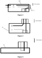
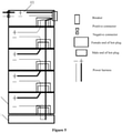
Figures 1 to 5 , a traditional energy storage cabinet includes abattery assembly 02, abase 01 and abattery management module 03, where thebattery assemblies 02 are multiple, and are stacked in sequence from top to bottom. Thebattery management module 03 is mounted at the top of thetop battery assembly 02 and electrically connected to thetop battery assembly 02. Thebase 01 has a short-circuit connection function. The positive and negative output ends of thebase 01 are electrically connected to thebottom battery assembly 02, and the topbattery management module 03 is equipped with a circuit breaker 03-1. - When the energy storage cabinet is assembled, the
bottom base 01 is first mounted, then thebattery assembly 02 is mounted from top to bottom, and finally the topbattery management module 03 is mounted. Ordinary energy storage cabinets do not have the function of charging other external electrical equipment, which is single in function, difficult in modification and not multifunctional. - Since the
battery management module 03 is located at the top of the energy storage cabinet and the circuit breaker is located at the top, the manual control system has poor convenience and safety for external output on and off, after the numbers of the stacking layers exceed the comfortable operating height of human body. - Therefore, how to improve the safety of workers operating the energy storage cabinet is an urgent technical problem to be solved by those skilled in the art.
- An object of the present application is to provide an energy storage cabinet to improve the safety of workers operating the energy storage cabinet.
- To achieve the above object, the present application provides an energy storage cabinet, including a battery management module and a battery assembly electrically connected to the battery assembly. The battery management module is located on a side wall of the battery assembly.
- Preferably, the energy storage cabinet further includes a base mounted below the bottommost battery assembly, and the base is provided with an electrical connection assembly whose two ends are respectively electrically connected to the bottommost battery assembly and the battery management module.
- Preferably, the base is electrically connected to the battery assembly and the battery management module through a hot-plug assembly.
- Preferably, the battery management module is mounted on the base, and the battery management module is detachably connected to the base, and the base is detachably connected to the battery assembly.
- Preferably, the battery management module is electrically connected to the battery assembly through a hot-plug assembly or a cable assembly.
- Preferably, the battery management module is mounted on the battery assembly.
- Preferably, the battery management module is fixedly connected to the battery assembly in a detachable manner.
- Preferably, one of the battery management module and the battery assembly is provided with a clamping groove, and the other is provided with a buckle for clamping the clamping groove. When the buckle is matched with the clamping groove, a side wall of the battery management module is fit with the side wall of the battery assembly.
- Preferably, multiple battery assemblies are provided, all the battery assemblies are stacked in sequence from top to bottom, and two adjacent battery assemblies are detachably connected to each other.
- Preferably, two adjacent battery assemblies are electrically connected through a hot-plug assembly or a cable assembly.
- Preferably, the energy storage cabinet further includes a top cover mounted above the top battery assembly, where a power conversion module and/or a fuse electrically connected to the top battery assembly is arranged in the top cover, and the battery management module includes a circuit breaker and/or a relay.
- Preferably, the power conversion module comprises a first positive terminal and a first negative terminal, and interface positions of the first positive terminal and the first negative terminal are reserved on the side, top or bottom of the top cover.
- Preferably, the top cover is fixedly connected to the top battery assembly in the detachable manner.
- Preferably, the battery assembly includes an outer shell and an electric core assembly. The outer shell includes a lower shell with an open at a top end and an upper cover plate for blocking the lower shell, and the electric core assembly is placed in the inner cavity of the lower shell. One of a bottom end of the lower shell and a top end of the upper cover plate is provided with at least one first handle, and the other is provided with at least one first limiting groove for accommodating the first handle on the adjacent battery assembly, where the at least one first handle is in one-to one correspondence with the first limiting groove.
- Preferably, the first handle is arranged on the upper cover plate, and the first limiting groove is arranged at the bottom end of the lower shell. The top end of the base is provided with a second handle mounted in the first limiting groove of the bottom battery assembly. The top cover is provided with a second limiting groove for mounting the first handle of the top battery assembly.
- Preferably, the first handle is fixedly connected to the side wall of the first limiting groove matched with the first handle in the detachable manner. The second handle fixedly connected to the side wall of the first limiting groove matched with the second handle in the detachable manner. The first handle is fixedly connected to the side wall of the second limiting groove matched with the first handle in the detachable manner.
- Preferably, the side wall of the lower shell is provided with a U-shaped groove body that opens outwards and is used for accommodating the battery management module.
- Preferably, the outer shell further includes a sealing plate used for sealing the side opening of the U-shaped groove body, and the sealing plate is detachably connected to the lower shell.
- Preferably, opposite side walls of the lower shell are provided with U-shaped sliding grooves with upper openings, and the sealing plate is slidably arranged in the U-shaped sliding grooves.
- In the above technical solutions, the energy storage cabinet according to the present application includes a battery management module and a battery assembly, where the battery management module is positioned on the side wall of the battery assembly and is electrically connected to the battery assembly.
- It can be seen from the above description that in the energy storage cabinet according to the present application, because the battery management module is located on the side wall of the battery assembly, the mounting height of the battery management module is effectively reduced, which is convenient for workers to control the battery management module, further facilitates the operation of the energy storage cabinet, and improves the safety of workers operating the energy storage cabinet.
- For more clearly illustrating embodiments of the present application or technical solutions in the conventional technology, the drawing referred to for describing the embodiments or the conventional technology will be briefly described hereinafter. Apparently, the drawings in the following description are only some examples of the present application, and for those skilled in the art, other drawings may be obtained based on the provided drawing without any creative efforts.
-
Figure 1 is a schematic diagram showing the structure of a conventional energy storage cabinet; -
Figure 2 is a circuit connection distribution diagram of a conventional battery management module; -
Figure 3 is a circuit connection distribution diagram of a conventional battery assembly; -
Figure 4 is a circuit connection distribution diagram of a conventional base; -
Figure 5 is a circuit connection distribution diagram of a conventional energy storage cabinet; -
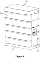
Figure 6 is a three-dimensional structural diagram of an energy cabinet according to an embodiment of the present application; -
Figure 7 is a three-dimensional structural diagram of an energy cabinet from another perspective according to an embodiment of the present application; -
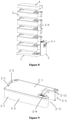
Figure 8 is an exploded view of an energy cabinet according to an embodiment of the present application; -
Figure 9 is a three-dimensional structural diagram of a battery assembly according to an embodiment of the present application; -
Figure 10 is a three-dimensional structural diagram of a battery management module according to an embodiment of the present application; -
Figure 11 is a three-dimensional structural diagram of a base according to an embodiment of the present application; -
Figure 12 is a circuit connection distribution diagram of an energy storage cabinet according to an embodiment of the present application; -
Figure 13 is a circuit connection distribution diagram of a battery management module according to an embodiment of the present application; -
Figure 14 is a circuit connection distribution diagram of a base according to an embodiment of the present application; -
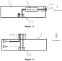
Figure 15 is a circuit connection distribution diagram of a top cover according to an embodiment of the present application; -
Figure 16 is a circuit connection distribution diagram of a battery assembly according to an embodiment of the present application; -
Figure 17 is a circuit connection distribution diagram of another battery assembly according to an embodiment of the present application; -
Figure 18 is a circuit connection distribution diagram of another top cover according to an embodiment of the present application; -
Figure 19 is a circuit connection distribution diagram of another base according to an embodiment of the present application; and -
Figure 20 is a circuit connection distribution diagram of another battery management module according to an embodiment of the present application. - A core of the present application is to provide an energy storage cabinet, so as to improve the safety of workers operating the energy storage cabinet.
- In order to enable those skilled in the art to better understand the technical solutions of the present application, the present application will be further described in detail below with reference to the accompanying drawings and embodiments.
-
Figures 6 to20 are referred. - In a specific embodiment, the energy storage cabinet according to an embodiment of the present application includes a
battery management module 3 and abattery assembly 2. Thebattery management module 3 is located on the side wall of thebattery assembly 2, and thebattery management module 3 is electrically connected to thebattery assembly 2. - Preferably, there are
multiple battery assemblies 2, all thebattery assemblies 2 are stacked in sequence from top to bottom, and twoadjacent battery assemblies 2 are electrically connected. Preferably, the number of thebattery assemblies 2 is greater than or equal to 3. - The
battery management module 3 may be mounted on thebattery assembly 2, and thebattery management module 3 is mounted on the side wall of thebattery assembly 2. Specifically, thebattery management module 3 may be electrically connected to thebattery assembly 2 in a direct manner; and preferably, thebattery management module 3 is connected to thebattery assembly 2 through a hot-plug assembly or a cable assembly. - To facilitate disassembly and assembly, it is preferable that the
battery management module 3 is fixedly connected to thebattery assembly 2 in a detachable manner. Specifically, thebattery management module 3 and thebattery assembly 2 may be connected by buckles or threaded fasteners. - Specifically, one of the
battery management module 3 and thebattery assembly 2 is provided with a clamping groove, and the other is provided with a buckle for clamping the clamping groove. When the buckle is matched with the clamping groove, the side wall of thebattery management module 3 is fit with the side wall of thebattery assembly 2. - In another embodiment, the
battery management module 3 is electrically connected to thebattery assembly 2 in an indirect manner. Thebattery management module 3 is connected to thebattery assembly 2 through external components. - In a specific embodiment, the energy storage cabinet further includes a
base 1 mounted below thebottommost battery assembly 2, and an electrical connection assembly with both ends electrically connected to thebottommost battery assembly 2 and thebattery management module 3 is arranged in thebase 1. - To facilitate disassembly and assembly, it is preferable that the
base 1 is electrically connected to thebattery assembly 2 and thebattery management module 3 through the hot-plug assembly. - In a specific embodiment, the
battery management module 3 is mounted on thebase 1, and thebattery management module 3 is detachably connected to thebase 1, and thebase 1 is detachably connected to thebattery assembly 2. - Two
adjacent battery assemblies 2 are electrically connected through hot-plug assemblies or cable assemblies, and twoadjacent battery assemblies 2 are detachably connected to each other. Thetop cover 4 is fixedly connected to thetop battery assembly 2 in a detachable manner. In this application, the detachable connection can be realized by threaded connection or buckle connection. - In a specific embodiment, the energy storage cabinet further comprises a
top cover 4 mounted on thetop battery assembly 2, and apower conversion module 5 electrically connected to thetop battery assembly 2 is arranged in thetop cover 4. Of course, thetop cover 4 may further be provided with a fuse. - The
battery management module 3 includes a circuit breaker and/or a relay, and when the circuit breaker is provided, the circuit breaker is electrically connected to thepower conversion module 5. - Specifically, interface positions of the first positive terminal 5-1 and the first negative terminal 5-2 of the
power conversion module 5 are reserved on the side, top or bottom of thetop cover 4. - When there are
multiple battery assemblies 2, all thebattery assemblies 2 are the first battery assembly, the second battery assembly... the M-1 battery assembly and the M battery assembly, and the first battery assembly, the second battery assembly, the M-1 battery assembly and M battery assembly are sequentially stacked from bottom to top. - Each
battery assembly 2 is provided with a first connection terminal 2-13 and a second connection terminal 2-14 located at the top of thebattery assembly 2, and a third connection terminal 2-15 and a fourth connection terminal 2-16 located at the bottom of thebattery assembly 2. The first connection terminal 2-13 and the third connection terminal 2-15 are a pair of connection terminals from which the positive and negative electrodes of the battery in thebattery assembly 2 are led out, and the second connection terminal 2-14 is connected to the fourth connection terminal 2-16 through the internal wiring of thebattery assembly 2. - The
top cover 4 is provided with a fifth connection terminal 4-2 and a sixth connection terminal 4-3 for electrical connection. The fifth connection terminal 4-2 is electrically connected to the first connection terminal 2-13 of the M battery assembly. The sixth connection terminal 4-3 is electrically connected to the second connection terminal 2-14 of the M battery assembly. - The third connection terminal 2-15 of the
upper battery assembly 2 of the twoadjacent battery assemblies 2 is connected to the first connection terminal 2-13 of thelower battery assembly 2. The fourth connection terminal 2-16 of theupper battery assembly 2 is connected to the second connection terminal 2-14 of thelower battery assembly 2 to realize the electrical connection between the top and the bottom of the battery assembly. - The
base 1 is provided with a seventh connection terminal 1-4, an eighth connection terminal 1-5, a ninth connection terminal 1-6 and a tenth connection terminal 1-7. The seventh connection terminal 1-4 and the ninth connection terminal 1-6 are communicated through the internal wiring, and the eighth connection terminal 1-5 and the tenth connection terminal 1-7 are communicated through the internal wiring. The seventh connection terminal 1-4 is connected to the third connection terminal 2-15 of the first battery assembly, and the eighth connection terminal 1-5 is connected to the fourth connection terminal 2-16 of the first battery assembly. The ninth connection terminal 1-6 and the tenth connection terminal 1-7 are respectively electrically connected to the positive and negative terminals of thebattery management module 3. - The
battery management module 3 includes a circuit breaker 3-1. Specifically, the side wall of thebattery management module 3 is provided with a second positive connector 3-3 and a second negative connector 3-4 connected to the circuit breaker 3-1, and the circuit breaker 3-1 is provided on the side wall of thebattery management module 3. Of course, in the actual production process, the positions of the circuit breaker 3-1, the second positive connector 3-3 and the second negative connector 3-4 may be changed as required. - The
battery management module 3 is provided with an eleventh connection terminal 3-5 and a twelfth connection terminal 3-6 connected to the circuit breaker 3-1. The eleventh connection terminal 3-5 is connected to the ninth connection terminal 1-6, and the twelfth connection terminal 3-6 is connected to the tenth terminal 1-7. - The
battery assembly 2 may be a conventional battery assembly, and the internal circuit is the same as the conventional circuit connection. - Preferably, the
battery management module 3 of the present application is placed on the side wall of thebattery assembly 2 and the upper part of thebase 1, preferably projected from top to bottom, and thetop cover 4, thebattery assembly 2 and thebattery management module 3 are projected in the projection of thebase 1. - From the above description, it can be known that in the energy storage cabinet according to the specific embodiment of the present application, because the wires in the
base 1 are not conductive during the mounting process, the connection ports of thebattery assembly 2 are free of voltage during the stacking process or the disassembly process, which makes the mounting and disassembly process safe and reliable. That is, the present application adopts a safe power line connection solution, which has high electrical safety and no risk of electric shock to personnel during stacking mounting and maintenance. During the mounting process, the circuit breaker 3-1 of thebattery management module 3 is always turned off, and the wires in thebase 1 are not conductive, so the port of the quick plug-in assembly of the module is free of voltage during the stacking process, which is safe and reliable during the mounting process. Therefore, the safety of workers in disassembling and assembling the energy storage cabinet is improved. - In this application, the
battery management module 3 is mounted from the top layer to the lower position of the side part of the energy storage cabinet; in the mounting process, the height of thebattery management module 3 remains unchanged, and the height of thebattery management module 3 will not increase with the increase of the stacking height. The height of thebattery management module 3 is moderate, which is convenient for mounting, wiring and later maintenance, and improves the safety of workers operating the energy storage cabinet. - The
battery assembly 2 is connected to thebattery management module 3 in power and signal manner on thebase 1. - Specifically, the
base 1 is equipped with two quick-plug terminals, namely the hot-plug assembly of first base 1-2 and the hot-plug assembly of second base 1-3. Specifically, the hot-plug assembly of first base 1-2 and the hot-plug assembly of second base 1-3 may both be female connector terminals. - The
battery management module 3 is equipped with two quick-plug terminals, which are the output terminal of the circuit breaker and the connector port of the power. The output terminal of the circuit breaker and the connector port of the power may both be male connector terminals. - The current loop of the
battery assembly 2 is connected in sequence through the hot-plug assembly of the first battery 2-8 and the hot-plug assembly of the second battery 2-9, and is arranged in series. The hot-plug assembly of the first battery 2-8 of one of twoadjacent battery assemblies 2 is connected to the hot-plug assembly of the second battery 2-9 of the other of the twobattery assemblies 2. Independent modular battery module is designed, battery expansion and cutting is flexible, it is not limited by the size and space of the cabinet itself, and no additional cabinets are required. In a specific embodiment, thebattery assembly 2 includes an outer shell, and the outer shell includes a lower shell 2-5 with an open at a top end and an upper cover 2-1 for blocking the lower shell 2-5. One of a bottom end of the lower shell 2-5 and a top end of the upper cover plate 2-1 is provided with at least one first handle 2-2, and the other is provided with at least one first limiting groove for accommodating the first handle 2-2 on theadjacent battery assembly 2, the at least one first handle 2-2 is in one-to one correspondence with the first limiting groove. Preferably, the upper cover plate 2-1 is detachably connected to the lower shell 2-5. Preferably, the first handle 2-2 is mounted by a threaded fastener 2-3. - The lower shell 2-5 is provided with a short side wall 2-4 and a long side wall 2-7 perpendicular to the short side wall 2-4, and the
battery management module 3 is preferably mounted on the short side wall 2-4. - Specifically, the first handle 2-2 may be arranged at the bottom end of the lower shell 2-5, and the first limiting groove is arranged on the upper cover plate 2-1.
- In another specific embodiment, the first handle 2-2 is arranged on the upper cover plate 2-1, and the first limiting groove is arranged at the bottom end of the lower shell 2-5. The top end of the
base 1 is provided with a second handle 1-1 mounted in the first limiting groove of thebottom battery assembly 2, and thetop cover 4 is provided with a second limiting groove for mounting the first handle 2-2 of thetop battery assembly 2. Preferably, the first handle 2-2 and the second handle 1-1 are handles with the same structure. - Preferably, the first handle 2-2 is fixedly connected to the side wall of the first limiting groove matched with the first handle in a detachable manner. The second handle 1-1 is fixedly connected to the side wall of the first limiting groove matched with the second handle in the detachable manner. The first handle 2-2 is fixedly connected to the side wall of the second limiting groove matched with the first handle in the detachable manner. Specifically, the side wall of the lower shell 2-5 is provided with mounting holes 2-10 matched with the first handle 2-2, and the first handle 2-2 and the second handle 1-1 can be fastened with the lower shell 2-5 or the
top cover 4 through threaded fasteners. Specifically, threaded fasteners may be mounting holes 2-10. In this application, the first handle 2-2 and the second handle 1-1 are limited by the first limiting groove and the second limiting groove, and locked by the threaded fasteners, so that the first handle 2-2 and the second handle 1-1 integrate the dual functions of limiting and fastening, without extra handles, saving space and cost. - In order to facilitate taking and placing the
battery assemblies 2, it is preferable that eachbattery assembly 2 is provided with two of the first handles 2-2 and two of the first limiting grooves. - In a specific embodiment, the side wall of the lower shell 2-5 is provided with a U-shaped groove 2-11 that opens outwards and is used to accommodate the
battery management module 3. Specifically, the height of thebattery management module 3 is preferably an integer multiple of the height of thebattery assembly 2. By arranging the U-shaped groove body 2-11 for accommodating thebattery management module 3, the energy storage cabinet has an overall appearance, is convenient to place, and has high overall stability. - Preferably, the outer shell further includes a sealing plate 2-6 for sealing the side opening of the U-shaped groove body 2-11, and the sealing plate 2-6 is detachably connected to the lower shell 2-5. The sealing plate 2-6 may be connected to the lower shell 2-5 through fasteners.
- In order to facilitate disassembly and assembly of the sealing plate 2-6, preferably, two opposite side walls of the lower shell 2-5 are provided with U-shaped sliding grooves 2-12 with upper openings, and the sealing plate 2-6 is slidably arranged in the U-shaped sliding grooves 2-12. Specifically, there are two U-shaped sliding grooves 2-12, and the opposite ends of the sealing plate 2-6 respectively extend into the corresponding U-shaped sliding grooves 2-12. The sealing plate 2-6 slides along the U-shaped sliding groove 2-12 during disassembly and assembly, which is simple and convenient to operate.
- On the basis of the above solutions, it is preferable that the energy storage cabinet further includes a
power conversion module 5, which is connected to the circuit breaker 3-1. Specifically, the circuit breaker 3-1 may electrically connect thepower conversion module 5 and thebattery assembly 2. - The
power conversion module 5 is the DC/DCpower conversion module 5, which realizes the functional compatible coupling between the energy storage machine and the charger machine, saving cost and space. - Specifically, the
power conversion module 5 is located in the inner cavity of thetop cover 4, and thetop cover 4 is provided with a first positive terminal 5-1 and a first negative terminal 5-2 for connecting with the circuit output of thepower conversion module 5. Apower conversion module 5 is added to thetop cover 4, so that the energy storage cabinet can store energy, and can also charge other electrical equipment with different voltage levels, thus realizing the functional compatible coupling of the energy storage machine and the charger machine, and saving cost and space. - A thirteenth connection terminal 4-4 and a fourteenth connection terminal 4-5 for connecting with the
power conversion module 5 are provided on thetop cover 4. - Preferably, the downward projections of the
base 1, the battery assembly and thetop cover 4 coincide. - Each
battery assembly 2 is provided with a fifteenth connection terminal 2-17 and a sixteenth connection terminal 2-18 at the top of thebattery assembly 2, and a seventeenth connection terminal 2-19 and an eighteenth connection terminal 2-20 at the bottom of thebattery assembly 2. The fifteenth connection terminal 2-17 is connected to the seventeenth connection terminal 2-19 through the internal wiring of thebattery assembly 2, and the sixteenth connection terminal 2-18 is connected to the eighteenth connection terminal 2-20 through the internal wiring of thebattery assembly 2. - In the two
adjacent battery assemblies 2, the eighteenth connection terminal 2-20 of theupper battery assembly 2 is connected to the sixteenth connection terminal 2-18 of thelower battery assembly 2, and the seventeenth connection terminal 2-19 of theupper battery assembly 2 is connected to the fifteenth connection terminal 2-17 of thelower battery assembly 2. - The fifteenth connection terminal 2-17 and the sixteenth connection terminal 2-18 of the M battery assembly are respectively connected to the thirteenth connection terminal 4-4 and the fourteenth connection terminal 4-5.
- The
base 1 is provided with a nineteenth connection terminal 1-8, a twentieth connection terminal 1-9, a twenty-first connection terminal 1-10, and a twenty-second connection terminal 1-11. The nineteenth connection terminal 1-8 is connected to the twenty-first connection terminal 1-10 through internal wiring, and the twentieth connection terminal 1-9 is connected to the twenty-second connection terminal 1-11 through internal wiring. The seventeenth connection terminal 2-19 and the eighteenth connection terminal 2-20 of the first battery assembly are respectively connected to the nineteenth connection terminal 1-8 and the twentieth connection terminal 1-9. - The
battery management module 3 includes a twenty-third connection terminal and a twenty-fourth connection terminal connected to the circuit breaker. The twenty-first connection terminal 1-10 is electrically connected to the twenty-third connection terminal, and the twenty-second connection terminal 1-11 is electrically connected to the twenty-fourth terminal. In this application, the two power harnesses led out from the circuit breaker 3-1 in thebattery management module 3 are directly led to thetop cover 4 through the transmission of each layer of thebattery assemblies 2, and then through the voltage conversion of the power conversion module, the entire energy storage cabinet can also charge other electrical equipment with different voltage levels without additional connection lines. - Specifically, the
top cover 4 is provided with a top cover hot-plug assembly 4-1 for integrating the terminals of the fifth connection terminal 4-2, the sixth connection terminal 4-3, the thirteenth connection terminal 4-4 and the fourteenth connection terminal 4-5. - The top of each
battery assembly 2 is provided with a hot-plug assembly 2-8 of the first battery for integrating the first connection terminal 2-13, the second connection terminal 2-14, the fifteenth connection terminal 2-17 and the sixteenth connection terminal 2-18. - The bottom of each
battery assembly 2 is provided with a hot-plug assembly 2-9 of the second battery for integrating the third connection terminal 2-15, the fourth connection terminal 2-16, the seventeenth connection terminal 2-19 and the eighteenth connection terminal 2-20. - The
base 1 is provided with a hot-plug assembly of the first base 1-2 integrating the seventh connection terminal 1-4, the eighth connection terminal 1-5, the nineteenth connection terminal 1-8 and the twentieth connection terminal 1-9. - The
base 1 is provided with a hot-plug assembly of the second base 1-3 integrating the ninth connection terminal 1-6, the tenth connection terminal 1-7, the twenty-first connection terminal 1-10 and the twenty-second connection terminal 1-11. - The
battery management module 3 is provided with a hot-plug assembly 3-2 of the power supply integrating the eleventh connection terminal 3-5, twelfth connection terminal 3-6, twenty-third connection terminal 3-7 and twenty-fourth connection terminal 3-8. - One of the two adjacent terminals is a male terminal and the other is a female terminal. The electrical connection between the components of the application is realized by mating the male and female ends of the quick-plug terminals, avoiding on-site mounting the wiring, and the mounting is convenient and quick. The quick-plug terminals include the functions of power transmission and signal transmission. Specifically, one of the hot-plug assembly of the first battery 2-8 and the hot-plug assembly of the second battery 2-9 is a male connector terminal, and the other is a female connector terminal.
- In a specific embodiment, the first positive terminal 5-1 and the first negative terminal 5-2 of the
power conversion module 5 are mounted on the side wall of thetop cover 4. The first positive terminal 5-1 and the first negative terminal 5-2 are arranged on the side wall of thetop cover 4, which is convenient for overall use even if other structures are mounted above thetop cover 4. - The above embodiments are described in a progressive manner. Each of the embodiments is mainly focused on describing its differences from other embodiments, and references may be made among these embodiments with respect to the same or similar parts.
- The above illustration of the disclosed embodiments can enable those skilled in the art to implement or use the present application. Various modifications to the embodiments are apparent to the person skilled in the art, and the general principle herein can be implemented in other embodiments without departing from the spirit or scope of the present application. Therefore, the present application is not limited to the embodiments described herein, but should be in accordance with the broadest scope consistent with the principle and novel features disclosed herein.
| 01 base | 02 battery assembly |
| 03 battery management module | 03-1 circuit breaker |
| 1 base | 1-1 second handle |
| 1-2 hot-plug assembly of first base | 1-3 hot-plug assembly of second base |
| 1-4 seventh connection terminal | 1-5 eighth connection terminal |
| 1-6 ninth connection terminal | 1-7 tenth connection terminal |
| 1-8 nineteenth connection terminal | 1-9 twentieth connection terminal |
| 1-10 twenty-first connection terminal | 1-11 twenty-second connection terminal |
| 2 battery assembly | 2-1 upper cover plate |
| 2-2 first handle | 2-3 threaded fastener |
| 2-4 short side wall | 2-5 lower shell |
| 2-6 sealing plate | 2-7 long side wall |
| 2-8 hot-plug assembly of first battery | 2-9 hot-plug assembly of second battery |
| 2-10 mounting hole | 2-11 U-shaped groove body |
| 2-12 U-shaped sliding groove | 2-13 first connection terminal |
| 2-14 second connection terminal | 2-15 third connection terminal |
| 2-16 fourth connection terminal | 2-17 fifteenth connection terminal |
| 2-18 sixteenth connection terminal | 2-19 seventeenth connection terminal |
| 2-20 eighteenth connection terminal | |
| 3 battery management module | 3-1 circuit breaker |
| 3-2 hot-plug assembly of power supply | 3-3 second positive connector |
| 3-4 second negative connector | 3-5 eleventh connection terminal |
| 3-6 twelfth connection terminal | 3-7 twenty-third connection terminal |
| 3-8 twenty-fourth connection terminal | 4 top cover |
| 4-1 hot-plug assembly of top cover | 4-2 fifth connection terminal |
| 4-3 sixth connection terminal | 4-4 thirteenth connection terminal |
| 4-5 fourteenth connection terminal | 5 power conversion module |
| 5-1 first positive terminal | 5-2 first negative terminal |
Claims (15)
- An energy storage cabinet, comprising:a battery management module (3); anda battery assembly (2) electrically connected to the battery assembly (2), whereinthe battery management module (3) is located on a side wall of the battery assembly (2).
- The energy storage cabinet according to claim 1, further comprising a base (1) mounted below the bottommost battery assembly (2), wherein the base (1) is provided with an electrical connection assembly whose two ends are respectively electrically connected to the bottommost battery assembly (2) and the battery management module (3).
- The energy storage cabinet according to claim 2, wherein the base (1) is electrically connected to the battery assembly (2) and the battery management module (3) through a hot-plug assembly.
- The energy storage cabinet according to claim 2, wherein the battery management module (3) is mounted on the base (1), the battery management module (3) is detachably connected to the base (1), and the base (1) is detachably connected to the battery assembly (2).
- The energy storage cabinet according to claim 1, wherein the battery management module (3) is electrically connected to the battery assembly (2) through a hot-plug assembly or a cable assembly.
- The energy storage cabinet according to claim 1, wherein the battery management module (3) is mounted on the battery assembly (2), and the battery management module (3) is fixedly connected to the battery assembly (2) in a detachable manner.
- The energy storage cabinet according to claim 6, wherein one of the battery management module (3) and the battery assembly (2) is provided with a clamping groove, and the other is provided with a buckle for clamping the clamping groove, and when the buckle is matched with the clamping groove, a side wall of the battery management module (3) is fit with the side wall of the battery assembly (2).
- The energy storage cabinet according to claim 1, wherein a plurality of battery assemblies (2) are provided, all the plurality of battery assemblies (2) are stacked in sequence from top to bottom, and two adjacent battery assemblies (2) are detachably connected to each other.
- The energy storage cabinet according to claim 8, wherein two adjacent battery assemblies (2) are electrically connected through a hot-plug assembly or a cable assembly.
- The energy storage cabinet according to claim 1, further comprising a top cover (4) mounted above the top battery assembly (2), wherein a power conversion module (5) and/or a fuse electrically connected to the top battery assembly (2) is arranged in the top cover (4), and the battery management module (3) comprises a circuit breaker and/or a relay.
- The energy storage cabinet according to claim 10, wherein the power conversion module (5) comprises a first positive terminal (5-1) and a first negative terminal (5-2), and interface positions of the first positive terminal (5-1) and the first negative terminal (5-2) are reserved on the side, top or bottom of the top cover (4).
- The energy storage cabinet according to claim 1, wherein the battery assembly (2) comprises an outer shell, the outer shell comprises a lower shell (2-5) with an open at a top end and an upper cover plate (2-1) for blocking the lower shell (2-5), one of a bottom end of the lower shell (2-5) and a top end of the upper cover plate (2-1) is provided with at least one first handle (2-2), and the other is provided with at least one first limiting groove for accommodating the first handle (2-2) on the adjacent battery assembly (2), wherein the at least one first handle is in one-to one correspondence with the at least one first limiting groove.
- The energy storage cabinet according to claim 12, wherein the first handle (2-2) is arranged on the upper cover plate (2-1), and the first limiting groove is arranged at the bottom end of the lower shell (2-5), the top end of the base (1) is provided with a second handle (1-1) mounted in the first limiting groove of the bottom battery assembly (2), and the top cover (4) is provided with a second limiting groove for mounting the first handle (2-2) of the top battery assembly (2); and
the first handle (2-2) is fixedly connected to the side wall of the first limiting groove matched with the first handle (2-2) in the detachable manner, the second handle (1-1) is fixedly connected to the side wall of the first limiting groove matched with the second handle (1-1) in the detachable manner, and the first handle (2-2) is fixedly connected to the side wall of the second limiting groove matched with the first handle (2-2) in the detachable manner. - The energy storage cabinet according to claim 12, wherein the side wall of the lower shell (2-5) is provided with a U-shaped groove body (2-11) that opens outwards and is used for accommodating the battery management module (3).
- The energy storage cabinet according to claim 14, wherein the outer shell further comprises a sealing plate (2-6) used for sealing a side opening of the U-shaped groove body (2-11), and the sealing plate (2-6) is detachably connected to the lower shell (2-5).
Applications Claiming Priority (1)
| Application Number | Priority Date | Filing Date | Title |
|---|---|---|---|
| CN202010849840.0A CN111900502A (en) | 2020-08-21 | 2020-08-21 | Energy storage cabinet |
Publications (1)
| Publication Number | Publication Date |
|---|---|
| EP3958372A1 true EP3958372A1 (en) | 2022-02-23 |
Family
ID=73229908
Family Applications (1)
| Application Number | Title | Priority Date | Filing Date |
|---|---|---|---|
| EP21151035.9A Pending EP3958372A1 (en) | 2020-08-21 | 2021-01-11 | Energy storage cabinet |
Country Status (5)
| Country | Link |
|---|---|
| US (1) | US12519163B2 (en) |
| EP (1) | EP3958372A1 (en) |
| JP (1) | JP7239620B2 (en) |
| CN (1) | CN111900502A (en) |
| AU (1) | AU2021200027B2 (en) |
Cited By (3)
| Publication number | Priority date | Publication date | Assignee | Title |
|---|---|---|---|---|
| CN117335284A (en) * | 2023-09-06 | 2024-01-02 | 石家庄市易源电力设备有限公司 | Combined alternating-current low-voltage power distribution cabinet |
| EP4333176A1 (en) * | 2022-08-24 | 2024-03-06 | Sungrow Energy Storage Technology Co., Ltd. | Household energy storage system and module fixing structure thereof |
| CN118610685A (en) * | 2024-08-12 | 2024-09-06 | 合肥华宇智航动力能源有限公司 | A superimposed household energy storage battery |
Families Citing this family (17)
| Publication number | Priority date | Publication date | Assignee | Title |
|---|---|---|---|---|
| CN112421166A (en) * | 2020-12-01 | 2021-02-26 | 珠海格力电器股份有限公司 | Battery module and energy storage cabinet |
| KR102826530B1 (en) * | 2020-12-07 | 2025-06-26 | 주식회사 엘지에너지솔루션 | A board type ESS battery pack |
| CN113131027A (en) * | 2021-04-14 | 2021-07-16 | 东莞市德富新能源有限公司 | Power supply device and power supply system with same |
| CN215644823U (en) * | 2021-07-28 | 2022-01-25 | 天合光能股份有限公司 | Energy storage unit and energy storage battery using the same |
| USD1025913S1 (en) * | 2021-12-27 | 2024-05-07 | Sungrow Power Supply Co., Ltd. | Energy storage container |
| CN216750120U (en) * | 2022-02-24 | 2022-06-14 | 上海派能能源科技股份有限公司 | Stack type battery pack and battery cabinet |
| CN217415508U (en) * | 2022-03-14 | 2022-09-13 | 阳光储能技术有限公司 | Household energy storage system with charging pile |
| CN116979636A (en) * | 2022-04-28 | 2023-10-31 | 苏州宝时得电动工具有限公司 | Energy storage power supply and its installation method |
| CN114843691B (en) * | 2022-05-11 | 2025-07-04 | 启东沃太新能源有限公司 | Energy storage equipment |
| CN115133207A (en) * | 2022-07-30 | 2022-09-30 | 三一重工股份有限公司 | Battery system unit, battery system, electric working machine, and battery replacement station |
| CN117638411B (en) * | 2022-08-31 | 2024-10-29 | 比亚迪股份有限公司 | Energy storage cabinet and energy storage system |
| EP4597710A4 (en) * | 2022-12-20 | 2026-03-18 | Lg Energy Solution Ltd | BATTERY PACK WITH IMPROVED SAFETY |
| USD1028892S1 (en) * | 2023-01-18 | 2024-05-28 | Xiamen Ampack Technology Limited | Energy storage device |
| CN220273355U (en) * | 2023-07-10 | 2023-12-29 | 江苏天合清特电气有限公司 | Energy storage system all-in-one and power supply system |
| CN220774627U (en) * | 2023-07-28 | 2024-04-12 | 华为数字能源技术有限公司 | Energy storage device, energy storage system and battery pack with stacked structure |
| USD1047909S1 (en) * | 2023-11-13 | 2024-10-22 | Shenzhen Ampower New Energy Co., Ltd. | Energy storage power supply |
| CN222146638U (en) * | 2024-04-07 | 2024-12-10 | 深圳得道未来科技有限公司 | Power supply mechanism with threaded connection |
Citations (4)
| Publication number | Priority date | Publication date | Assignee | Title |
|---|---|---|---|---|
| EP2543093A2 (en) * | 2010-03-04 | 2013-01-09 | Jacques Philemon Antoine De Kegel | Rechargeable battery for an electric vehicle, vehicle comprising such a battery, method and system for replacing a rechargeable battery of an electric vehicle; and system for transferring energy to the battery |
| EP3522313A1 (en) * | 2016-09-30 | 2019-08-07 | BYD Company Limited | Power supply cabinet |
| EP3528314A1 (en) * | 2018-02-16 | 2019-08-21 | FERRARI S.p.A. | Vehicular battery pack |
| CN210806350U (en) * | 2019-09-27 | 2020-06-19 | 比亚迪股份有限公司 | Power supply cabinet |
Family Cites Families (20)
| Publication number | Priority date | Publication date | Assignee | Title |
|---|---|---|---|---|
| KR100936262B1 (en) * | 2005-10-21 | 2010-01-12 | 주식회사 엘지화학 | A bus bar for electrical connection with a novel structure and a battery module including the same |
| WO2010009536A1 (en) * | 2008-07-21 | 2010-01-28 | Kirk Schroeder | Portable power supply device |
| JP5537111B2 (en) * | 2009-09-30 | 2014-07-02 | 株式会社東芝 | Secondary battery device |
| JP2011175743A (en) * | 2010-02-23 | 2011-09-08 | Sanyo Electric Co Ltd | Power source apparatus, and vehicle equipped with the same |
| JP2011216424A (en) * | 2010-04-02 | 2011-10-27 | Hitachi Vehicle Energy Ltd | Power storage module |
| US9293755B2 (en) * | 2011-09-14 | 2016-03-22 | Battery Street Energy, Inc. | Intelligent battery pack module |
| KR101883915B1 (en) * | 2011-09-30 | 2018-08-02 | 삼성에스디아이 주식회사 | Battery module having support member |
| JP5630431B2 (en) * | 2011-12-13 | 2014-11-26 | 株式会社デンソー | Assembled battery |
| US9065192B2 (en) * | 2013-09-19 | 2015-06-23 | Tyco Electronics Corporation | Power terminal connector |
| FR3007202B1 (en) * | 2013-06-13 | 2016-12-09 | Commissariat Energie Atomique | BATTERY COMPRISING A MODULE CHAIN ASSEMBLY |
| JP6044505B2 (en) * | 2013-10-22 | 2016-12-14 | 株式会社デンソー | Battery pack unit |
| KR20150106735A (en) * | 2014-03-12 | 2015-09-22 | 주식회사 엘지화학 | Battery pack |
| CN204375820U (en) * | 2015-02-10 | 2015-06-03 | 阳光电源股份有限公司 | A kind of battery cabinet and modular battery cabinet, assembled battery cabinet |
| JP6855913B2 (en) * | 2017-05-10 | 2021-04-07 | 株式会社デンソー | Control module |
| JP6851020B2 (en) | 2017-06-01 | 2021-03-31 | パナソニックIpマネジメント株式会社 | Storage battery unit |
| JP6751058B2 (en) * | 2017-07-18 | 2020-09-02 | 矢崎総業株式会社 | Battery module and battery monitoring unit mounting structure |
| JP6860449B2 (en) * | 2017-08-30 | 2021-04-14 | ビークルエナジージャパン株式会社 | Battery module |
| EP3884540A4 (en) * | 2018-11-22 | 2023-03-08 | Corvus Energy Inc. | BATTERY MODULE AND BATTERY MODULE STACK |
| CN209133567U (en) * | 2018-11-27 | 2019-07-19 | 肇庆乐创科技有限公司 | A kind of high-capacity button lithium battery |
| CN209029457U (en) * | 2018-12-17 | 2019-06-25 | 河北零点新能源科技有限公司 | A kind of modular battery for capableing of Rapid Combination |
-
2020
- 2020-08-21 CN CN202010849840.0A patent/CN111900502A/en active Pending
-
2021
- 2021-01-05 AU AU2021200027A patent/AU2021200027B2/en active Active
- 2021-01-11 EP EP21151035.9A patent/EP3958372A1/en active Pending
- 2021-01-15 JP JP2021005167A patent/JP7239620B2/en active Active
- 2021-01-27 US US17/160,147 patent/US12519163B2/en active Active
Patent Citations (4)
| Publication number | Priority date | Publication date | Assignee | Title |
|---|---|---|---|---|
| EP2543093A2 (en) * | 2010-03-04 | 2013-01-09 | Jacques Philemon Antoine De Kegel | Rechargeable battery for an electric vehicle, vehicle comprising such a battery, method and system for replacing a rechargeable battery of an electric vehicle; and system for transferring energy to the battery |
| EP3522313A1 (en) * | 2016-09-30 | 2019-08-07 | BYD Company Limited | Power supply cabinet |
| EP3528314A1 (en) * | 2018-02-16 | 2019-08-21 | FERRARI S.p.A. | Vehicular battery pack |
| CN210806350U (en) * | 2019-09-27 | 2020-06-19 | 比亚迪股份有限公司 | Power supply cabinet |
Cited By (5)
| Publication number | Priority date | Publication date | Assignee | Title |
|---|---|---|---|---|
| EP4333176A1 (en) * | 2022-08-24 | 2024-03-06 | Sungrow Energy Storage Technology Co., Ltd. | Household energy storage system and module fixing structure thereof |
| AU2023204407B2 (en) * | 2022-08-24 | 2025-01-23 | Sungrow Energy Storage Technology Co., Ltd. | Household energy storage system and module fixing structure thereof |
| CN117335284A (en) * | 2023-09-06 | 2024-01-02 | 石家庄市易源电力设备有限公司 | Combined alternating-current low-voltage power distribution cabinet |
| CN117335284B (en) * | 2023-09-06 | 2024-04-09 | 石家庄市易源电力设备有限公司 | Combined alternating-current low-voltage power distribution cabinet |
| CN118610685A (en) * | 2024-08-12 | 2024-09-06 | 合肥华宇智航动力能源有限公司 | A superimposed household energy storage battery |
Also Published As
| Publication number | Publication date |
|---|---|
| JP2022035943A (en) | 2022-03-04 |
| CN111900502A (en) | 2020-11-06 |
| US20220059895A1 (en) | 2022-02-24 |
| US12519163B2 (en) | 2026-01-06 |
| AU2021200027B2 (en) | 2022-09-08 |
| JP7239620B2 (en) | 2023-03-14 |
| AU2021200027A1 (en) | 2022-03-10 |
Similar Documents
| Publication | Publication Date | Title |
|---|---|---|
| US12519163B2 (en) | Energy storage cabinet | |
| US20220069596A1 (en) | Charging Post Controller with Functional Modules Connected by Means of PCB, and Charging Post Thereof | |
| JP2022035942A (en) | Lamination type power supply cabinet | |
| CN210668809U (en) | Polyhedral socket | |
| CN221805745U (en) | High-voltage stacked energy storage battery pack and stacked energy storage system | |
| CN215771256U (en) | Battery device | |
| CN221531055U (en) | Low-voltage household battery storage system with double protection functions | |
| CN222283067U (en) | A fusion PCS energy storage and conversion device | |
| CN119812805A (en) | Integrated plug-in components and energy storage system | |
| CN218887387U (en) | Install convenient horizontal energy storage system of stacking family | |
| CN219498987U (en) | Stacked integrated energy storage system | |
| CN213716947U (en) | Energy storage cabinet | |
| CN218102681U (en) | Energy storage system | |
| CN216016057U (en) | Energy router | |
| CN213692170U (en) | Digital energy storage module | |
| CN222146321U (en) | Battery management system, distribution box, battery pack and electric equipment | |
| CN223194266U (en) | A distribution box for energy storage system | |
| CN223261067U (en) | Terminal hidden high-voltage control box structure and energy storage device | |
| CN217720786U (en) | Bidirectional charging and discharging machine | |
| CN213813730U (en) | Electric energy meter connector with short circuit function | |
| CN223364396U (en) | Modularized control unit and charging pile | |
| CN218400219U (en) | Energy storage high-voltage box for electric vehicle battery | |
| CN215580483U (en) | Temporary supply device for operating locking power supply of 10kV cabinet | |
| CN218788677U (en) | Portable UPS power supply device | |
| CN221137591U (en) | Battery replacement system and vehicle |
Legal Events
| Date | Code | Title | Description |
|---|---|---|---|
| PUAI | Public reference made under article 153(3) epc to a published international application that has entered the european phase |
Free format text: ORIGINAL CODE: 0009012 |
|
| STAA | Information on the status of an ep patent application or granted ep patent |
Free format text: STATUS: REQUEST FOR EXAMINATION WAS MADE |
|
| 17P | Request for examination filed |
Effective date: 20211222 |
|
| AK | Designated contracting states |
Kind code of ref document: A1 Designated state(s): AL AT BE BG CH CY CZ DE DK EE ES FI FR GB GR HR HU IE IS IT LI LT LU LV MC MK MT NL NO PL PT RO RS SE SI SK SM TR |
|
| STAA | Information on the status of an ep patent application or granted ep patent |
Free format text: STATUS: EXAMINATION IS IN PROGRESS |
|
| 17Q | First examination report despatched |
Effective date: 20240603 |