EP3958248A1 - Image generation device and image generation method - Google Patents
Image generation device and image generation method Download PDFInfo
- Publication number
- EP3958248A1 EP3958248A1 EP20790668.6A EP20790668A EP3958248A1 EP 3958248 A1 EP3958248 A1 EP 3958248A1 EP 20790668 A EP20790668 A EP 20790668A EP 3958248 A1 EP3958248 A1 EP 3958248A1
- Authority
- EP
- European Patent Office
- Prior art keywords
- image
- data
- format
- display
- frame buffer
- Prior art date
- Legal status (The legal status is an assumption and is not a legal conclusion. Google has not performed a legal analysis and makes no representation as to the accuracy of the status listed.)
- Granted
Links
Images









Classifications
-
- G—PHYSICS
- G09—EDUCATION; CRYPTOGRAPHY; DISPLAY; ADVERTISING; SEALS
- G09G—ARRANGEMENTS OR CIRCUITS FOR CONTROL OF INDICATING DEVICES USING STATIC MEANS TO PRESENT VARIABLE INFORMATION
- G09G5/00—Control arrangements or circuits for visual indicators common to cathode-ray tube indicators and other visual indicators
- G09G5/36—Control arrangements or circuits for visual indicators common to cathode-ray tube indicators and other visual indicators characterised by the display of a graphic pattern, e.g. using an all-points-addressable [APA] memory
- G09G5/39—Control of the bit-mapped memory
- G09G5/395—Arrangements specially adapted for transferring the contents of the bit-mapped memory to the screen
-
- G—PHYSICS
- G09—EDUCATION; CRYPTOGRAPHY; DISPLAY; ADVERTISING; SEALS
- G09G—ARRANGEMENTS OR CIRCUITS FOR CONTROL OF INDICATING DEVICES USING STATIC MEANS TO PRESENT VARIABLE INFORMATION
- G09G5/00—Control arrangements or circuits for visual indicators common to cathode-ray tube indicators and other visual indicators
- G09G5/02—Control arrangements or circuits for visual indicators common to cathode-ray tube indicators and other visual indicators characterised by the way in which colour is displayed
-
- A—HUMAN NECESSITIES
- A63—SPORTS; GAMES; AMUSEMENTS
- A63F—CARD, BOARD, OR ROULETTE GAMES; INDOOR GAMES USING SMALL MOVING PLAYING BODIES; VIDEO GAMES; GAMES NOT OTHERWISE PROVIDED FOR
- A63F13/00—Video games, i.e. games using an electronically generated display having two or more dimensions
- A63F13/50—Controlling the output signals based on the game progress
- A63F13/52—Controlling the output signals based on the game progress involving aspects of the displayed game scene
-
- G—PHYSICS
- G06—COMPUTING OR CALCULATING; COUNTING
- G06T—IMAGE DATA PROCESSING OR GENERATION, IN GENERAL
- G06T5/00—Image enhancement or restoration
- G06T5/50—Image enhancement or restoration using two or more images, e.g. averaging or subtraction
-
- G—PHYSICS
- G06—COMPUTING OR CALCULATING; COUNTING
- G06T—IMAGE DATA PROCESSING OR GENERATION, IN GENERAL
- G06T5/00—Image enhancement or restoration
- G06T5/90—Dynamic range modification of images or parts thereof
- G06T5/92—Dynamic range modification of images or parts thereof based on global image properties
-
- G—PHYSICS
- G09—EDUCATION; CRYPTOGRAPHY; DISPLAY; ADVERTISING; SEALS
- G09G—ARRANGEMENTS OR CIRCUITS FOR CONTROL OF INDICATING DEVICES USING STATIC MEANS TO PRESENT VARIABLE INFORMATION
- G09G5/00—Control arrangements or circuits for visual indicators common to cathode-ray tube indicators and other visual indicators
- G09G5/003—Details of a display terminal, the details relating to the control arrangement of the display terminal and to the interfaces thereto
- G09G5/005—Adapting incoming signals to the display format of the display terminal
-
- G—PHYSICS
- G09—EDUCATION; CRYPTOGRAPHY; DISPLAY; ADVERTISING; SEALS
- G09G—ARRANGEMENTS OR CIRCUITS FOR CONTROL OF INDICATING DEVICES USING STATIC MEANS TO PRESENT VARIABLE INFORMATION
- G09G5/00—Control arrangements or circuits for visual indicators common to cathode-ray tube indicators and other visual indicators
- G09G5/10—Intensity circuits
-
- G—PHYSICS
- G09—EDUCATION; CRYPTOGRAPHY; DISPLAY; ADVERTISING; SEALS
- G09G—ARRANGEMENTS OR CIRCUITS FOR CONTROL OF INDICATING DEVICES USING STATIC MEANS TO PRESENT VARIABLE INFORMATION
- G09G5/00—Control arrangements or circuits for visual indicators common to cathode-ray tube indicators and other visual indicators
- G09G5/14—Display of multiple viewports
-
- G—PHYSICS
- G09—EDUCATION; CRYPTOGRAPHY; DISPLAY; ADVERTISING; SEALS
- G09G—ARRANGEMENTS OR CIRCUITS FOR CONTROL OF INDICATING DEVICES USING STATIC MEANS TO PRESENT VARIABLE INFORMATION
- G09G5/00—Control arrangements or circuits for visual indicators common to cathode-ray tube indicators and other visual indicators
- G09G5/36—Control arrangements or circuits for visual indicators common to cathode-ray tube indicators and other visual indicators characterised by the display of a graphic pattern, e.g. using an all-points-addressable [APA] memory
-
- G—PHYSICS
- G09—EDUCATION; CRYPTOGRAPHY; DISPLAY; ADVERTISING; SEALS
- G09G—ARRANGEMENTS OR CIRCUITS FOR CONTROL OF INDICATING DEVICES USING STATIC MEANS TO PRESENT VARIABLE INFORMATION
- G09G5/00—Control arrangements or circuits for visual indicators common to cathode-ray tube indicators and other visual indicators
- G09G5/36—Control arrangements or circuits for visual indicators common to cathode-ray tube indicators and other visual indicators characterised by the display of a graphic pattern, e.g. using an all-points-addressable [APA] memory
- G09G5/37—Details of the operation on graphic patterns
- G09G5/377—Details of the operation on graphic patterns for mixing or overlaying two or more graphic patterns
-
- G—PHYSICS
- G06—COMPUTING OR CALCULATING; COUNTING
- G06T—IMAGE DATA PROCESSING OR GENERATION, IN GENERAL
- G06T2207/00—Indexing scheme for image analysis or image enhancement
- G06T2207/20—Special algorithmic details
- G06T2207/20172—Image enhancement details
- G06T2207/20208—High dynamic range [HDR] image processing
-
- G—PHYSICS
- G06—COMPUTING OR CALCULATING; COUNTING
- G06T—IMAGE DATA PROCESSING OR GENERATION, IN GENERAL
- G06T2207/00—Indexing scheme for image analysis or image enhancement
- G06T2207/20—Special algorithmic details
- G06T2207/20212—Image combination
- G06T2207/20221—Image fusion; Image merging
-
- G—PHYSICS
- G09—EDUCATION; CRYPTOGRAPHY; DISPLAY; ADVERTISING; SEALS
- G09G—ARRANGEMENTS OR CIRCUITS FOR CONTROL OF INDICATING DEVICES USING STATIC MEANS TO PRESENT VARIABLE INFORMATION
- G09G2320/00—Control of display operating conditions
- G09G2320/06—Adjustment of display parameters
- G09G2320/0666—Adjustment of display parameters for control of colour parameters, e.g. colour temperature
-
- G—PHYSICS
- G09—EDUCATION; CRYPTOGRAPHY; DISPLAY; ADVERTISING; SEALS
- G09G—ARRANGEMENTS OR CIRCUITS FOR CONTROL OF INDICATING DEVICES USING STATIC MEANS TO PRESENT VARIABLE INFORMATION
- G09G2320/00—Control of display operating conditions
- G09G2320/06—Adjustment of display parameters
- G09G2320/0673—Adjustment of display parameters for control of gamma adjustment, e.g. selecting another gamma curve
-
- G—PHYSICS
- G09—EDUCATION; CRYPTOGRAPHY; DISPLAY; ADVERTISING; SEALS
- G09G—ARRANGEMENTS OR CIRCUITS FOR CONTROL OF INDICATING DEVICES USING STATIC MEANS TO PRESENT VARIABLE INFORMATION
- G09G2340/00—Aspects of display data processing
- G09G2340/10—Mixing of images, i.e. displayed pixel being the result of an operation, e.g. adding, on the corresponding input pixels
-
- G—PHYSICS
- G09—EDUCATION; CRYPTOGRAPHY; DISPLAY; ADVERTISING; SEALS
- G09G—ARRANGEMENTS OR CIRCUITS FOR CONTROL OF INDICATING DEVICES USING STATIC MEANS TO PRESENT VARIABLE INFORMATION
- G09G2340/00—Aspects of display data processing
- G09G2340/12—Overlay of images, i.e. displayed pixel being the result of switching between the corresponding input pixels
-
- G—PHYSICS
- G09—EDUCATION; CRYPTOGRAPHY; DISPLAY; ADVERTISING; SEALS
- G09G—ARRANGEMENTS OR CIRCUITS FOR CONTROL OF INDICATING DEVICES USING STATIC MEANS TO PRESENT VARIABLE INFORMATION
- G09G2360/00—Aspects of the architecture of display systems
- G09G2360/18—Use of a frame buffer in a display terminal, inclusive of the display panel
-
- G—PHYSICS
- G09—EDUCATION; CRYPTOGRAPHY; DISPLAY; ADVERTISING; SEALS
- G09G—ARRANGEMENTS OR CIRCUITS FOR CONTROL OF INDICATING DEVICES USING STATIC MEANS TO PRESENT VARIABLE INFORMATION
- G09G2370/00—Aspects of data communication
- G09G2370/02—Networking aspects
-
- G—PHYSICS
- G09—EDUCATION; CRYPTOGRAPHY; DISPLAY; ADVERTISING; SEALS
- G09G—ARRANGEMENTS OR CIRCUITS FOR CONTROL OF INDICATING DEVICES USING STATIC MEANS TO PRESENT VARIABLE INFORMATION
- G09G2370/00—Aspects of data communication
- G09G2370/20—Details of the management of multiple sources of image data
Definitions
- the present invention relates to an image generation apparatus and an image generation method for generating a display image.
- HDR high dynamic range
- SDR standard dynamic range
- the processing required for image display has become more complicated as a result of various combinations of conditions, such as which luminance range the original image data is defined in and which luminance range a connected display supports.
- conditions such as which luminance range the original image data is defined in and which luminance range a connected display supports.
- a change in these conditions may, in some cases, cause the compositing result to change, resulting in image display different from the original intention.
- the present invention has been made in view of the problems described above. It is an object of the present invention to provide a technique that can appropriately control the compositing result regardless of conditions when a plurality of images are composited and displayed.
- the image generation apparatus includes an image data generating section configured to generate data of a display image, a frame buffer configured to store data of an image generated, a format control section configured to, in a case where the image generating section starts alpha compositing of a plurality of images, switch a data format of pixel values to be stored in the frame buffer, and an output section configured to read the data of the image from the frame buffer, convert the data into a format corresponding to a display, and output resulting data.
- an image generation apparatus that generates data of a display image, stores the data in a frame buffer, and outputs the data includes a step of, in a case where alpha compositing of a plurality of images starts, switching a data format of pixel values to be stored in the frame buffer, a step of generating data of the plurality of images, alpha compositing the data, and storing resulting data in the frame buffer, and a step of reading the data of an image from the frame buffer, converting the data into a format corresponding to a display, and outputting resulting data.
- the compositing result when a plurality of images are composited and displayed, the compositing result can be appropriately controlled regardless of conditions.
- FIG. 1 illustrates an example of a configuration of an image display system according to the present embodiment.
- the image display system includes an image generation apparatus 10, an input apparatus 14, and a display 16.
- the image generation apparatus 10 may be connected to a server or the like that provides various pieces of content via a network 8 such as the Internet.
- the input apparatus 14 may be a general input apparatus, such as a controller, a keyboard, a mouse, a joystick, or a touchpad, with which user operation can be performed, an imaging apparatus for photographing the real world, such as a user, a microphone for obtaining sound, a sensor for detecting various physical values, or a combination of any of them.
- the display 16 is implemented by a liquid-crystal display, a plasma display, an organic electroluminescent (EL) display, or the like that displays an image. Additionally, the display 16 may also include a speaker to output sound.
- the input apparatus 14 and the display 16 may be connected to the image generation apparatus 10 through a wired cable or may be wirelessly connected to the image generation apparatus 10 through a wireless local area network (LAN) or the like. Further, the external shapes of the input apparatus 14, the display 16, and the image generation apparatus 10 are not limited to those illustrated in the figure. For example, two or more of them may be integrally formed.
- the image generation apparatus 10 receives signals related to a user operation from the input apparatus 14, performs processing in response thereto, generates data of a display image, and outputs the data to the display 16.
- the image generation apparatus 10 may be any of a game machine, a personal computer, a tablet terminal, a mobile terminal, a mobile phone, and the like. Depending on the form of the image generation apparatus 10 or an application or the like selected by the user, the contents of the processing performed by the image generation apparatus 10 may vary.
- the image generation apparatus 10 causes an electronic game specified by the user to progress in response to a user operation and generates and outputs data of a game screen of the electronic game at a predetermined frame rate.
- the image generation apparatus 10 may obtain data of a moving image from the server via the network 8 and decode and output the data sequentially. Since the purpose of use of the image generation apparatus 10 may vary and contents of information processing to be performed vary accordingly as described above, the detailed description is omitted. The following description focuses mainly on a method for suitably displaying an image of content generated as a result of such information processing, an image representing information to be presented, or the like.
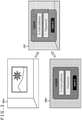
- FIG. 2 schematically illustrates an example of images generated by the image generation apparatus 10 in the present embodiment.
- a main image 200a is, for example, an image that is mainly displayed, such as a game screen or a moving image.
- An additional image 200b is, for example, an image that is temporarily displayed if necessary, and the example illustrated in the figure includes a dialog box that allows the user to enter an address and password for login.
- the image generation apparatus 10 superimposes the additional image 200b including the dialog box on the main image 200a that has been originally displayed, and generates and outputs a display image 202.
- the main image 200a is made visible through the additional image 200b as a wide region as possible, so that necessary information can be suitably integrated without interrupting the view of the world of the main image 200a, such as a game or a moving image.
- the transparency of the additional image 200b can be changed over time to produce an effect of making the dialog box gradually appear or disappear.
- a color value C out of each pixel of the display image 202 can be determined on the basis of the calculation of alpha compositing represented by the following equation.
- C out 1 ⁇ ⁇ C 1 + ⁇ C 2
- C 1 and C 2 respectively represent color values of the corresponding pixels of the main image 200a and the additional image 200b
- ⁇ represents a general ⁇ value set for the corresponding pixel of the additional image 200b, that is, a value of 0 or greater and 1.0 or less indicating the degree of transparency.
- the additional image 200b For example, changing the ⁇ value from 0 to 1.0 in the entire image gradually turns the color of the additional image 200b darker from a state in which only the main image 200a is displayed, and the additional image 200b is eventually displayed opaquely. If the ⁇ value is set to an intermediate value that is greater than 0 and less than 1.0, the additional image 200b becomes translucent with the density corresponding to this value. Accordingly, the main image 200a is visible through the additional image 200b.
- the color values C 1 and C 2 are set to each of these three channels. In the present embodiment, however, they are collectively referred to as the color values C 1 and C 2 . Further, each of the color values C 1 and C 2 and the ⁇ value is set for each pixel. Thus, strictly speaking, the color values C 1 and C 2 and the ⁇ value depend on two-dimensional position coordinates (x, y) on an image plane. However, since Equation 1 assumes the calculation of pixels at the same position, the position coordinates are not presented. This similarly applies to the following description.
- FIG. 3 illustrates an internal circuit configuration of the image generation apparatus 10.
- the image generation apparatus 10 includes a central processing unit (CPU) 22, a graphics processing unit (GPU) 24, and a main memory 26. Each of these units is connected to each other via a bus 30. Additionally, a communication section 32, a storage section 34, an output section 36, an input section 38, and a recording medium driving section 40 are also connected to the bus 30.
- the communication section 32 includes a peripheral device interface such as universal serial bus (USB) or Institute of Electrical and Electronics Engineers (IEEE) 1394 or a wired or wireless LAN network interface for connecting to the network 8 or the like.
- the storage section 34 is a hard disk drive, a non-volatile memory, or the like.
- the output section 36 outputs video signals to the display 16.
- the input section 38 receives data from the input apparatus 14.
- the recording medium driving section 40 drives a removable recording medium such as a magnetic disk, an optical disc, or a semiconductor memory.
- the CPU 22 controls the entire image generation apparatus 10 by executing an operating system stored in the storage section 34.
- the CPU 22 also executes various programs that are read from the removable recording medium and loaded into the main memory 26 or downloaded via the communication section 32.
- the communication section 32 may also establish communication with an external apparatus, such as the server, via the network 8 to obtain data of electronic content such as a moving image or to transmit data generated inside the image generation apparatus 10.
- the main memory 26 includes a random access memory (RAM).
- the main memory 26 includes a frame buffer 70 that stores image data to be displayed.
- the main memory 26 also stores programs and data necessary for processing.
- the GPU 24 has a function of a geometry engine and a function of a rendering processor to perform rendering processing according to a rendering instruction from the CPU 22 and store resulting data in the frame buffer 70.
- the output section 36 reads the data of the image from the frame buffer 70 and outputs the data of the image as video signals to the display 16 at an appropriate timing.
- FIG. 4 is a diagram for describing a general processing flow related to video signals.
- a pixel value before quantization of an image rendered by the GPU 24 or the like of the image generation apparatus 10 is an input value while a color value that should thereby be represented is an output value.
- the two values have a linear relationship.
- the data is quantized by an optical-electro transfer function (OETF) as illustrated in (b).
- OETF optical-electro transfer function
- Different functions are used for an image whose luminance range is defined by SDR and an image whose luminance range is defined by HDR, so that SDR or HDR video signals having a predetermined color depth are generated.
- the output section 36 reads the video signals from the frame buffer 70 and supplies the video signals to the display 16.
- the display 16 converts the video signals into luminance values by an electro-optical transfer function (EOTF) as illustrated in (c).
- EOTF electro-optical transfer function
- a luminance value in the range of 0 to 100 nits is obtained for each pixel in the case of an SDR image while a luminance value in the range of 0 to 10000 nits, which is a different range from that of the SDR image, is obtained for each pixel in the case of an HDR image.
- Each luminance value is further corrected according to the luminance characteristic of a display panel, and then sequentially output at an appropriate timing. Accordingly, the image is displayed in the corresponding luminance range.
- FIG. 5 illustrates basic processing flows for a case where two images are composited.
- one of a "luminance range A" and a “luminance range B” is, for example, for SDR while the other is for HDR.
- each pixel value of each image is generally quantized to a value within the range of 0 to 1.0.
- Equation 1 substituting each pixel value of the first and second images, which are to be composited, into Equation 1 as it is generates a composite image defined by the luminance range "A.” By outputting the composite image to the display 16, the composite image can thus be displayed.
- Represented in (b) is a case where the first image is rendered in the luminance range "A" corresponding to the display, while the second image is rendered in the luminance range "B" different from the luminance range "A.”
- the first image and the second image correspond to the main image 200a and the additional image 200b of FIG. 2 , respectively.
- a conceivable case is such that the former is displayed in HDR to achieve dynamic image representation while the SDR image provided by the system is superimposed thereon.
- the image generation apparatus 10 needs to convert the data of the second image into values in the luminance range A before substituting the values into Equation 1 and alpha compositing the first image and the second image.
- the luminance range conversion can be performed by mapping the SDR luminance range to part of the HDR luminance range. For example, the peak luminance (1.0) of SDR is mapped to the brightness of approximately 100 to 300 nits in the HDR luminance range, and the SDR value of 0 to 1.0 is mapped by linear interpolation.
- the luminance range conversion thereto.
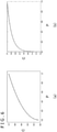
- FIG. 6 exemplifies conversion functions used to quantize the pixel values of image data.
- FIG. 7 illustrates schematic diagrams exemplifying the influence on the composite image due to the difference between the conversion functions used for quantization.
- (a) and (b) illustrated assume a case where the main image 200a and the additional image 200b illustrated in FIG. 2 are alpha composited.
- Represented in (a) of FIG. 7 is a case where both the main image and the additional image are SDR images and the display is also an SDR display, as illustrated in (a) of FIG. 5 . Therefore, everything is processed in the sRGB space.
- the main image is generated in HDR while the additional image is generated in SDR.
- the additional image is converted into data in the HDR luminance range.
- the characteristic with respect to luminance is also converted.
- the additional image which is an SDR image
- the additional image is composited after being converted from the data in the sRGB space into data in the PQ space.
- each color value of the composite image can be calculated by the weighted sum in the same space using Equation 1.
- the main image is less transmissive in a region in which the additional image is dark. This is due to the fact that, compared to the sRGB curve, the PQ curve increases the increase rate of the color value in a low luminance region, so that more weight is substantially applied to the image with lower luminance among the images to be composited.
- the conversion function is determined depending on the connected display, a composite image may be, in some cases, displayed in such a state that is not expected by the application or the system. Moreover, even when the same content is being displayed, the display impression may vary depending on the connected display. Therefore, in the present embodiment, the conversion function is determined independently of the luminance range of the display, so that images can be composited in that space.
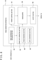
- FIG. 8 illustrates a configuration of functional blocks of the image generation apparatus 10 according to the present embodiment.
- the functional blocks illustrated in FIG. 8 can be implemented by the configurations of the CPU, the GPU, various memories, the data bus, and the like illustrated in FIG. 3 in terms of hardware and can be implemented by a program that is loaded into a memory from a recording medium or the like and that performs various functions, such as a data input function, a data retention function, a calculation function, an image processing function, and a communication function, in terms of software. Therefore, it is to be understood by those skilled in the art that these functional blocks can be implemented in various forms by hardware alone, software alone, or a combination thereof and are not limited to any of these forms.
- the image generation apparatus 10 includes an input information obtaining section 50, an image data generating section 52, a frame buffer 56, a format control section 54, and an output section 58.
- the input information obtaining section 50 obtains input information from the input apparatus 14.
- the image data generating section 52 generates data of a display image.
- the frame buffer 56 stores data of an image generated.
- the format control section 54 switches a data format of pixel values to be stored in the frame buffer 56.
- the output section 58 outputs the data of the display image to the display 16.
- the input information obtaining section 50 is implemented by the input section 38, the CPU 22, and the like of FIG. 3 and obtains data indicating the contents of a user operation from the input apparatus 14.
- the user operation may be an operation, such as the selection of an application or content to be executed, start/end of processing, or input of a command, which is performed on a general information processing apparatus, a mobile terminal, and a game apparatus.
- the input information obtaining section 50 may also obtain data of electronic content, such as a moving image, from the server via the network 8.
- the input information obtaining section 50 supplies the obtained data to the image data generating section 52 and the format control section 54 as appropriate.
- the image data generating section 52 is implemented by the CPU 22, the GPU 24, and the like of FIG. 3 and generates an image to be displayed according to the contents of a user operation or the like.
- the image data generating section 52 includes an image rendering section 60 and a data conversion section 62.
- the image rendering section 60 generates an image that constitutes a display image, regardless of whether or not a plurality of images are composited.
- the image rendering section 60 causes the electronic game to progress according to a user operation and renders an image of the electronic game at a predetermined frame rate.
- the image rendering section 60 may decode and decompress data of a moving image specified by the user.
- the moving image may be obtained from an imaging apparatus as the input apparatus 14 or distributed from the server via the network 8.
- the moving image may be the one stored in a connected external storage apparatus or the like.
- a game image or a moving image generated in this manner will be referred to as a first image.
- the image rendering section 60 stores color values, which are obtained by quantizing the luminance of each pixel of the generated first image, in the frame buffer 56.
- the image rendering section 60 further generates a second image, if necessary.
- the second image may be displayed at any time by being called up by the user or may be displayed at a timing determined according to the progress of the game or the moving image. Alternatively, the second image may be displayed at all times in a corner of the screen. In any case, the second image is an image to be superimposed on the first image, and the degree of transparency at which the second image is displayed is set by the ⁇ value.
- the ⁇ value may be set for each pixel or each region. Alternatively, the ⁇ value may be fixed in the entire image. Further, the setting value may be changed over time.
- the image rendering section 60 first stores quantized color values of the first image in the frame buffer 56, and overwrites the data by calculating weighted sums of the quantized color values of the first image and quantized color values of the second image.
- the data conversion section 62 converts the luminance range of the image data that is subject to compositing, if necessary.
- the data conversion section 62 also converts the space of the image data that is subject to compositing, if necessary. In other words, the conversion is performed such that the pieces of data of the first and second images have values with a common characteristic with respect to luminance. For example, in a case where an SDR image and an HDR image are composited, the SDR image is converted from the sRGB space into the PQ space. Alternatively, the HDR image is converted from the PQ space into the sRGB space.
- the data conversion section 62 determines a conversion destination space independently of the space that is set by the connected display 16 when the display 16 processes video signals, that is, independently of the used EOTF. For example, even if the HDR display is connected, it is allowable to convert the first image, which is an HDR image, into the sRGB space. This makes it possible to display a composite image with transparency similar to that of a case where both images are SDR images and composited and displayed on the SDR display, as illustrated in (a) of FIG. 7 .
- the second image which is an SDR image
- the first image which is an HDR image.
- the second image is converted into the PQ space without converting the first image, which is an HDR image.
- the data conversion section 62 determines the one with higher priority on the basis of the settings in the application or the system causing the image to be displayed, and selects a corresponding space as the conversion destination.
- the format control section 54 is implemented by the CPU 22 of FIG. 3 and switches the data format of the pixel values to be stored in the frame buffer according to the space of the conversion destination selected by the data conversion section 62.
- the pixel values of an SRD image and an HDR image are each subject to tone compression mainly in a high-luminance region by the corresponding conversion function, and each color is converted so as to fit in a predetermined number of bits.
- using a function different from the conversion function originally supported may, in some cases, generate a case where the converted values cannot be stored in the same data format.
- the format control section 54 switches at least one of the bit depth of each color and whether a decimal point is fixed or float.
- the format control section 54 does not need to switch the format of the frame buffer 56.
- the frame buffer 56 stores data of images generated or composited by the image rendering section 60.
- the first image is first stored. Then, the results of the calculation of the pixel values of the first image and the pixel values of the second image are stored. These are carried out on the same data format under the control of the format control section 54.
- the output section 58 is implemented by the GPU 24, the output section 36, and the like of FIG. 3 and reads data of an image from the frame buffer 56 and sequentially outputs the data to the display 16.
- the output section 36 further spatially converts the data and outputs resulting data as video signals in a format suitable for the display 16.
- FIG. 9 is a diagram for describing the range of converted color values for a case where an HDR image is converted into the sRGB space as an example of the present embodiment.
- the graph in the figure represents the conversion function used for sRGB as in (a) of FIG. 6 .
- the upper limit of a pixel value P denoted on the horizontal axis that is, the range of the original luminance, is set to peak luminance Ph of HDR, which is larger than the peak luminance Ps of SDR.
- the peak luminance Ph of HDR is approximately 100 times the peak luminance Ps of SDR, the figure is schematically illustrated for the sake of clarity.
- the conversion function of sRGB converts luminance of 0 to Ps into a color value of 0 to 1.0. Meanwhile, if the same function is used to convert a wide range of HDR luminance, its maximum value Ch becomes larger than 1.0, as a matter of course.
- the PQ curve generally used for an HDR image also converts luminance into a color value of 1 to 1.0. Therefore, values obtained by converting the HDR image using the sRGB function cannot be fully stored in the frame buffer of the data format set for such general processing. Accordingly, the format control section 54 switches the format of the frame buffer 56 according to the conversion of the HDR image into the sRGB space.
- the table below illustrates typical examples of spatial conversions and data formats for the combinations of the luminance ranges of images to be composited and the luminance ranges of the displays that are set in the present embodiment.
- the color values originally represented in the sRGB space are converted into the PQ space. Accordingly, composited color values can be obtained in the PQ space through compositing using Equation 1. Further, since the converted SDR color values do not exceed 1.0, the composited color values also do not exceed 1.0, and the originally set data format suffices. However, in this case, as illustrated in (b) of FIG. 7 , the compositing result changes from the result of compositing the SDR images.
- the number of bits is preferentially assigned in the order of green, red, and blue, on the basis of the level of the visual sensitivity. Further, in this example, no storage region is provided for the ⁇ value. However, in a case where it is necessary to hold an ⁇ plane for each image that is subject to compositing, such as in a case where an additional image is composited on a composite image written to the frame buffer 56, bits also need to be assigned to the ⁇ value. Therefore, other than the examples illustrated in the table, the data format is selected appropriately according to various settings at the time of compositing and the number of bits that can be prepared for each pixel.
- the PQ space or the sRGB space is mainly used as the space in which alpha compositing is performed.
- an actual curve to be applied is not limited thereto as long as compositing is performed in the same space.
- compositing may be performed in the space such as gamma 2.2 or gamma 2.4 described above.
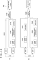
- FIG. 10 compares a procedure for generating a composite image of an SDR image and an HDR image, which is to be displayed on the HDR display, in the PQ space with a procedure for the same in the sRGB space.
- Represented in (a) is a case where compositing is performed in the PQ space.
- the HDR image is not converted (S10). Since the gamma curve conversion has been performed on the SDR image in the sRGB space, the data conversion section 62 once returns the data to a linear space having no curve (S12).
- EOTF illustrated in FIG. 4 can be used for this.
- the data conversion section 62 maps each value proportional to the original luminance obtained in this manner, to part of the HDR luminance range, thereby converting the value into the one in the HDR luminance range (S14). This is actually a process of extending a color gamut through matrix calculation, for which a known calculation method can be used. Then, the data conversion section 62 performs the PQ curve conversion on the data whose luminance range has been converted in this manner, to obtain data in the PQ space (S16). Accordingly, both of the images to be composited are represented in the PQ space. Therefore, both of the images are alpha composited using Equation 1, and the resulting data is stored in the frame buffer of "R10G10B10A2Unorm.”
- Represented in (b) is a case where compositing is performed in the sRGB space and the data conversion section 62 also converts the HDR image. That is, since the PQ curve conversion has been performed on the HDR image, the data conversion section 62 once returns the data of this image to the linear space having no curve using EOTF (S20). Then, the data conversion section 62 performs the sRGB curve conversion on the data to obtain data in the sRGB space (S22).
- the SDR image is converted into values in the HDR luminance range (S26).
- the data conversion section 62 performs the sRGB curve conversion on the data whose luminance range has been converted, to obtain data in the sRGB space (S28). Accordingly, both of the images to be composited are now represented in the sRGB space. Therefore, both of the images are alpha composited using Equation 1, and the resulting data is stored in the frame buffer of "R11G11B10Float.”
- FIG. 11 is a flowchart illustrating a processing procedure for the image generation apparatus 10 generating a display image and outputting the display image to the display.
- This processing procedure is based on the assumption that a main image of an electronic game or the like is generated in HDR and displayed on the HDR display.
- the image data generating section 52 when the input information obtaining section 50 obtains the contents of a user operation, the image data generating section 52 generates an HDR image according to the contents of the operation and the output section 58 reads data thereof from the frame buffer 56 and outputs the data to the display (S40). It is noted that the process of generating the display image is not limited to performing rendering on the moment when the user operation is performed and moving image data recorded by this time may be decoded, for example. Further, since only the HDR image is displayed, the frame buffer 56 uses the data format corresponding to the PQ space.
- the process of generating and outputting the HDR image continues (N in S42). If the SDR image needs to be composited on the HDR image (Y in S42), the data conversion section 62 determines which of the reproducibility of the composite image and the reproducibility of the HDR image is prioritized (S44). For example, in a case where a menu image provided by the system is called up for the purpose of changing settings or the like while an electronic game is being played, the reproducibility of the composite image is prioritized in order to produce a similar compositing state regardless of whether the main image is an SDR or HDR image.
- the reproducibility of the HDR image is prioritized in order to ensure that the main image is constantly of high quality. This is also the case where moving image content is reproduced.
- the data conversion section 62 detects the situation according to the user operation and the like obtained by the input information obtaining section 50 and determines the priority. In practice, this processing may be implemented by a logic circuit that determines which priority is higher.
- the format control section 54 switches the data format of the frame buffer 56 to the one corresponding to the sRGB space, so that color values of 1.0 or greater can be stored (S46).
- the image data generating section 52 then stores the result of alpha compositing of the HDR and SDR images converted into the sRGB space in the frame buffer 56 whose format has been switched, and the output section 58 reads and outputs the result (S48). At this time, the output section 58 converts the composite image represented in the sRGB space into video signals in the PQ space and outputs the video signals.
- the data format set in the frame buffer 56 with only the HDR image being displayed is left unchanged. This data format corresponds to the PQ space. Then, the image data generating section 52 converts the data of the SDR image into the data in the HDR luminance range and stores the result of alpha compositing with the HDR image in the PQ space in the frame buffer 56, and the output section 58 reads and outputs the result (S48).
- the process of storing a composite image in the frame buffer 56 in the same data format and outputting the composite image is repeated at a predetermined frame rate (S48).
- the processing returns to the generation and output of an HDR image in S40 while the display itself continues (N in S52). After that, the processes from S40 to S50 are repeated, and when the display needs to end, all the processes end (Y in S52).
- the determination criteria for switching between compositing of the SDR image and the HDR image in the PQ space and compositing of the SDR image and the HDR image in the sRGB space are exemplified.
- compositing in the PQ space maintains the quality of the HDR image
- compositing in the sRGB space achieves the reproducibility of the composite image. Therefore, in the following description, the former will be referred to as an "image-quality prioritizing mode,” and the latter will be referred to as a “compositing prioritizing mode.”
- the following criteria are set, for example.
- FIG. 12 exemplifies an example of the transition of images displayed in a case where the present embodiment is applied.
- This example is a situation in which the above-described 1 is applied.
- An image 100 is a home screen on which an application provided by the system is selected. During the period in which an image of such a configuration is displayed, the compositing prioritizing mode is set. In the image 100, assume that an application called "capture gallery" is selected.
- the "capture gallery” is an application in which a captured image taken during previous game play and representing how the play was going is viewed at a later timing. For example, an image during the game, such as an image 102, is displayed. During the period in which such an image is displayed, it is desirable to accurately reproduce how the game was going. Therefore, as illustrated on the left side of the figure, when the screen configuration is switched, the compositing prioritizing mode is switched to the image-quality prioritizing mode. Then, when the user finishes viewing and performs an operation of closing the image 102, an image 104 representing the home screen is displayed again. At this time, along with the switch to the home screen, the image-quality prioritizing mode is switched back to the compositing prioritizing mode.
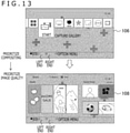
- FIG. 13 illustrates another example of the transition of images displayed in a case where the present embodiment is applied.
- This example represents a situation in which the above-described 2 is applied.
- An image 106 represents a case where many of component images (elements) that constitute the image are represented translucently. In this case, if the compositing result changes, the impression of the appearance changes significantly. Therefore, the compositing prioritizing mode is set to achieve a stable display.
- an image 108 represents a case where there are a few elements represented translucently. In this case, even if the compositing result changes, the impression does not change very much. Therefore, high-quality image display is maintained as the image-quality prioritizing mode.
- the switch between the two modes is determined according to a set threshold such as the number of elements represented translucently, the areas of images represented translucently, or the like, for example.
- FIG. 14 illustrates another example of the transition of images displayed in a case where the present embodiment is applied.
- this example represents a situation in which the above-described 3 is applied, this example is not limited to the transition between image-quality prioritizing mode and the compositing prioritizing mode.
- an image 110 is a menu screen provided by the system, while an image 112 is a game screen generated by the game content being executed.
- Images 114 and 116 are results of compositing of the images 110 and 112.
- the image 114 represents a composite image for a case where the content specifies compositing in the linear space.
- the data conversion section 62 composites the image 110 and the image 112 by converting the data of the image 110 and the image 112 into the linear space by EOTF or the like.
- the format control section 54 sets the frame buffer 56 to a data format that can store linearly quantized values.
- the data format set here is a floating-point format in which 16 bits are set for each of the primary colors and 16 bits are set for the ⁇ value. It is noted that the data format is not limited thereto.
- An image 115 is a composite image for a case where the content specifies compositing in a gamma 2.2 space. Accordingly, the data conversion section 62 sets the final conversion destination in (b) of FIG. 10 to the gamma 2.2 space.
- the format control section 54 sets a fixed-point format in which 8 bits are set for each of primary colors and 8 bits are set for the ⁇ value, for example. It is noted that the data format is not limited thereto. Allowing the compositing space to be specified in the content in this manner can always reflect the intention of the content creator. Therefore, the system may provide an application programming interface (API) for the content creator to specify the space.
- API application programming interface
- an apparatus that generates a display image can switch the data format of the frame buffer according to the situation. Accordingly, even if values that exceed the numerical range generally obtained are generated as a result of switching of the conversion function used for quantization of pixel values, the values can be written to the frame buffer as they are.
- This configuration can alleviate restrictions on the combination of the luminance range and the conversion function, such as an SDR image and the gamma curve such as sRGB or an HDR image and the PQ curve.
- the resulting representation can be similar to the one in a case where SDR images are composited.
- compositing can be performed in the PQ space without switching the data format. In this manner, even if the luminance range of the original image or the display changes in various ways, the mode of the display image can be controlled suitably.
- the present invention can be used for various apparatuses such as display apparatuses, content reproduction apparatuses, and game apparatuses, and systems including the apparatuses.
Landscapes
- Engineering & Computer Science (AREA)
- Physics & Mathematics (AREA)
- General Physics & Mathematics (AREA)
- Theoretical Computer Science (AREA)
- Computer Hardware Design (AREA)
- Multimedia (AREA)
- Image Processing (AREA)
- Controls And Circuits For Display Device (AREA)
- Studio Devices (AREA)
Abstract
Description
- The present invention relates to an image generation apparatus and an image generation method for generating a display image.
- Heretofore, various techniques for enhancing the image quality in video display of television broadcasting, a distributed moving image, and the like have been developed. In recent years, in addition to the technique for enhancing resolution and color gamut, a technique for processing signals in a high dynamic range (HDR) in which a luminance range is expanded has become popular. Since an allowable luminance range of HDR is approximately 100 times as large as that of a conventional standard dynamic range (SDR), an object, such as reflection of the sunlight, which is felt dazzled in the real world, can be more realistically represented even on an image. Not only in the television broadcasting and the distributed moving image, but also in the world of computer graphics such as a game image, the representation in HDR can provide more realistic sensations in the virtual world (for example, see PTL 1).
- [PTL 1]
Japanese Patent Laid-Open No. 2016-58848 - The processing required for image display has become more complicated as a result of various combinations of conditions, such as which luminance range the original image data is defined in and which luminance range a connected display supports. In particular, in a case where a plurality of images are composited and displayed, a change in these conditions may, in some cases, cause the compositing result to change, resulting in image display different from the original intention.
- The present invention has been made in view of the problems described above. It is an object of the present invention to provide a technique that can appropriately control the compositing result regardless of conditions when a plurality of images are composited and displayed.
- One aspect of the present invention relates to an image generation apparatus. The image generation apparatus includes an image data generating section configured to generate data of a display image, a frame buffer configured to store data of an image generated, a format control section configured to, in a case where the image generating section starts alpha compositing of a plurality of images, switch a data format of pixel values to be stored in the frame buffer, and an output section configured to read the data of the image from the frame buffer, convert the data into a format corresponding to a display, and output resulting data.
- Another aspect of the present invention relates to an image generation method. As the image generation method, an image generation apparatus that generates data of a display image, stores the data in a frame buffer, and outputs the data includes a step of, in a case where alpha compositing of a plurality of images starts, switching a data format of pixel values to be stored in the frame buffer, a step of generating data of the plurality of images, alpha compositing the data, and storing resulting data in the frame buffer, and a step of reading the data of an image from the frame buffer, converting the data into a format corresponding to a display, and outputting resulting data.
- It is noted that any combinations of the constituent components described above and the expressions of the present invention that are converted between a method, an apparatus, a system, a computer program, a recording medium in which the computer program is recorded, and the like are also effective as aspects of the present invention.
- According to the present invention, when a plurality of images are composited and displayed, the compositing result can be appropriately controlled regardless of conditions.
-
- [
FIG. 1 ]
FIG. 1 is a diagram illustrating an example of a configuration of an image display system according to the present embodiment. - [
FIG. 2 ]
FIG. 2 is a diagram schematically illustrating an example of images generated by an image generation apparatus according to the present embodiment. - [
FIG. 3 ]
FIG. 3 is a diagram illustrating an internal circuit configuration of the image generation apparatus according to the present embodiment. - [
FIG. 4 ]
FIG. 4 illustrates diagrams for describing a general processing flow related to video signals. - [
FIG. 5 ]
FIG. 5 illustrates diagrams of basic processing flows for a case where two images are composited. - [
FIG. 6 ]
FIG. 6 illustrates diagrams exemplifying conversion functions used to quantize pixel values of image data according to the present embodiment. - [
FIG. 7 ]
FIG. 7 illustrates schematic diagrams exemplifying an influence on a composite image due to the difference between conversion functions used for quantization in the present embodiment. - [
FIG. 8 ]
FIG. 8 is a diagram illustrating a configuration of functional blocks of the image generation apparatus according to the present embodiment. - [
FIG. 9 ]
FIG. 9 is a diagram for describing the range of converted color values for a case where an HDR image is converted into an sRGB space as an example of the present embodiment. - [
FIG. 10 ]
FIG. 10 illustrates diagrams comparing a procedure for generating a composite image of an SDR image and an HDR image, which is to be displayed on an HDR display, in a perceptual quantization (PQ) space with a procedure for the same in the sRGB space in the present embodiment. - [
FIG. 11 ]
FIG. 11 is a flowchart illustrating a processing procedure for the image generation apparatus according to the present embodiment generating a display image and outputting the display image to a display. - [
FIG. 12 ]
FIG. 12 is a diagram exemplifying the transition of images displayed in a case where the present embodiment is applied. - [
FIG. 13 ]
FIG. 13 is a diagram illustrating another example of the transition of images displayed in a case where the present embodiment is applied. - [
FIG. 14 ]
FIG. 14 is a diagram illustrating another example of the transition of images displayed in a case where the present embodiment is applied. -
FIG. 1 illustrates an example of a configuration of an image display system according to the present embodiment. The image display system includes animage generation apparatus 10, aninput apparatus 14, and adisplay 16. As illustrated in the figure, theimage generation apparatus 10 may be connected to a server or the like that provides various pieces of content via a network 8 such as the Internet. Theinput apparatus 14 may be a general input apparatus, such as a controller, a keyboard, a mouse, a joystick, or a touchpad, with which user operation can be performed, an imaging apparatus for photographing the real world, such as a user, a microphone for obtaining sound, a sensor for detecting various physical values, or a combination of any of them. - The
display 16 is implemented by a liquid-crystal display, a plasma display, an organic electroluminescent (EL) display, or the like that displays an image. Additionally, thedisplay 16 may also include a speaker to output sound. Theinput apparatus 14 and thedisplay 16 may be connected to theimage generation apparatus 10 through a wired cable or may be wirelessly connected to theimage generation apparatus 10 through a wireless local area network (LAN) or the like. Further, the external shapes of theinput apparatus 14, thedisplay 16, and theimage generation apparatus 10 are not limited to those illustrated in the figure. For example, two or more of them may be integrally formed. - The
image generation apparatus 10 receives signals related to a user operation from theinput apparatus 14, performs processing in response thereto, generates data of a display image, and outputs the data to thedisplay 16. Theimage generation apparatus 10 may be any of a game machine, a personal computer, a tablet terminal, a mobile terminal, a mobile phone, and the like. Depending on the form of theimage generation apparatus 10 or an application or the like selected by the user, the contents of the processing performed by theimage generation apparatus 10 may vary. - For example, the
image generation apparatus 10 causes an electronic game specified by the user to progress in response to a user operation and generates and outputs data of a game screen of the electronic game at a predetermined frame rate. Alternatively, theimage generation apparatus 10 may obtain data of a moving image from the server via the network 8 and decode and output the data sequentially. Since the purpose of use of theimage generation apparatus 10 may vary and contents of information processing to be performed vary accordingly as described above, the detailed description is omitted. The following description focuses mainly on a method for suitably displaying an image of content generated as a result of such information processing, an image representing information to be presented, or the like. -
FIG. 2 schematically illustrates an example of images generated by theimage generation apparatus 10 in the present embodiment. In this example, amain image 200a is, for example, an image that is mainly displayed, such as a game screen or a moving image. Anadditional image 200b is, for example, an image that is temporarily displayed if necessary, and the example illustrated in the figure includes a dialog box that allows the user to enter an address and password for login. When such a dialog box needs to be displayed, theimage generation apparatus 10 superimposes theadditional image 200b including the dialog box on themain image 200a that has been originally displayed, and generates and outputs adisplay image 202. - At this time, the
main image 200a is made visible through theadditional image 200b as a wide region as possible, so that necessary information can be suitably integrated without interrupting the view of the world of themain image 200a, such as a game or a moving image. Moreover, the transparency of theadditional image 200b can be changed over time to produce an effect of making the dialog box gradually appear or disappear. - It is to be understood by those skilled in the art that there are various other possible cases in which a plurality of images are displayed on top of each other, other than the example illustrated in the figure. For example, in the case of a racing game, it is conceivable to additionally display an additional image representing a bird's eye view of the entire course in addition to a main image representing the driver's field of view. In the case of displaying a movie, it is conceivable to additionally display an image representing bibliographic information such as a storyline and actors and an operation panel for reproduction, pausing, fast-forwarding, and the like.
- When the
display image 202 described above is generated, a color value Cout of each pixel of thedisplay image 202 can be determined on the basis of the calculation of alpha compositing represented by the following equation.
- Here, C1 and C2 respectively represent color values of the corresponding pixels of the
main image 200a and theadditional image 200b, while α represents a general α value set for the corresponding pixel of theadditional image 200b, that is, a value of 0 or greater and 1.0 or less indicating the degree of transparency. - For example, changing the α value from 0 to 1.0 in the entire image gradually turns the color of the
additional image 200b darker from a state in which only themain image 200a is displayed, and theadditional image 200b is eventually displayed opaquely. If the α value is set to an intermediate value that is greater than 0 and less than 1.0, theadditional image 200b becomes translucent with the density corresponding to this value. Accordingly, themain image 200a is visible through theadditional image 200b. - It is noted that, if the
main image 200a and theadditional image 200b are RGB images, the color values C1 and C2 are set to each of these three channels. In the present embodiment, however, they are collectively referred to as the color values C1 and C2. Further, each of the color values C1 and C2 and the α value is set for each pixel. Thus, strictly speaking, the color values C1 and C2 and the α value depend on two-dimensional position coordinates (x, y) on an image plane. However, since Equation 1 assumes the calculation of pixels at the same position, the position coordinates are not presented. This similarly applies to the following description. -
FIG. 3 illustrates an internal circuit configuration of theimage generation apparatus 10. Theimage generation apparatus 10 includes a central processing unit (CPU) 22, a graphics processing unit (GPU) 24, and amain memory 26. Each of these units is connected to each other via abus 30. Additionally, acommunication section 32, astorage section 34, anoutput section 36, aninput section 38, and a recordingmedium driving section 40 are also connected to thebus 30. Thecommunication section 32 includes a peripheral device interface such as universal serial bus (USB) or Institute of Electrical and Electronics Engineers (IEEE) 1394 or a wired or wireless LAN network interface for connecting to the network 8 or the like. Thestorage section 34 is a hard disk drive, a non-volatile memory, or the like. Theoutput section 36 outputs video signals to thedisplay 16. Theinput section 38 receives data from theinput apparatus 14. The recordingmedium driving section 40 drives a removable recording medium such as a magnetic disk, an optical disc, or a semiconductor memory. - The
CPU 22 controls the entireimage generation apparatus 10 by executing an operating system stored in thestorage section 34. TheCPU 22 also executes various programs that are read from the removable recording medium and loaded into themain memory 26 or downloaded via thecommunication section 32. Thecommunication section 32 may also establish communication with an external apparatus, such as the server, via the network 8 to obtain data of electronic content such as a moving image or to transmit data generated inside theimage generation apparatus 10. - The
main memory 26 includes a random access memory (RAM). Themain memory 26 includes aframe buffer 70 that stores image data to be displayed. Here, there is no limitation on the number of frame buffers. Further, themain memory 26 also stores programs and data necessary for processing. TheGPU 24 has a function of a geometry engine and a function of a rendering processor to perform rendering processing according to a rendering instruction from theCPU 22 and store resulting data in theframe buffer 70. Theoutput section 36 reads the data of the image from theframe buffer 70 and outputs the data of the image as video signals to thedisplay 16 at an appropriate timing. -
FIG. 4 is a diagram for describing a general processing flow related to video signals. In (a), a pixel value before quantization of an image rendered by theGPU 24 or the like of theimage generation apparatus 10 is an input value while a color value that should thereby be represented is an output value. As a matter of course, the two values have a linear relationship. When data having such a linear characteristic is stored in theframe buffer 70 of theimage generation apparatus 10, the data is quantized by an optical-electro transfer function (OETF) as illustrated in (b). Different functions are used for an image whose luminance range is defined by SDR and an image whose luminance range is defined by HDR, so that SDR or HDR video signals having a predetermined color depth are generated. - The
output section 36 reads the video signals from theframe buffer 70 and supplies the video signals to thedisplay 16. Thedisplay 16 converts the video signals into luminance values by an electro-optical transfer function (EOTF) as illustrated in (c). By appropriately selecting EOTF, even if signals have the same color depth, a luminance value in the range of 0 to 100 nits is obtained for each pixel in the case of an SDR image while a luminance value in the range of 0 to 10000 nits, which is a different range from that of the SDR image, is obtained for each pixel in the case of an HDR image. Each luminance value is further corrected according to the luminance characteristic of a display panel, and then sequentially output at an appropriate timing. Accordingly, the image is displayed in the corresponding luminance range. -
FIG. 5 illustrates basic processing flows for a case where two images are composited. In the figure, one of a "luminance range A" and a "luminance range B" is, for example, for SDR while the other is for HDR. Further, each pixel value of each image is generally quantized to a value within the range of 0 to 1.0. In (a), illustrated is an environment in which two images to be composited are rendered in the same luminance range "A," and thedisplay 16 also processes and displays video signals in the luminance range "A." In this case, substituting each pixel value of the first and second images, which are to be composited, into Equation 1 as it is generates a composite image defined by the luminance range "A." By outputting the composite image to thedisplay 16, the composite image can thus be displayed. - Represented in (b) is a case where the first image is rendered in the luminance range "A" corresponding to the display, while the second image is rendered in the luminance range "B" different from the luminance range "A." For example, assume that the first image and the second image correspond to the
main image 200a and theadditional image 200b ofFIG. 2 , respectively. In this case, a conceivable case is such that the former is displayed in HDR to achieve dynamic image representation while the SDR image provided by the system is superimposed thereon. - In this case, the
image generation apparatus 10 needs to convert the data of the second image into values in the luminance range A before substituting the values into Equation 1 and alpha compositing the first image and the second image. Here, the luminance range conversion can be performed by mapping the SDR luminance range to part of the HDR luminance range. For example, the peak luminance (1.0) of SDR is mapped to the brightness of approximately 100 to 300 nits in the HDR luminance range, and the SDR value of 0 to 1.0 is mapped by linear interpolation. However, there is no intention to limit the luminance range conversion thereto. - However, since the pixel values determined for each image are values that have been converted and quantized by the OETF described above (hereafter referred to as a conversion function), the assumed conversion function has an influence on the compositing result.
FIG. 6 exemplifies conversion functions used to quantize the pixel values of image data. Represented in (a) is a conversion function used in sRGB, which is the standard for an SDR color space. Assuming that an original pixel value, that is, luminance to be represented, is P and the color value after quantization is C, most of the range exhibits a gamma curve in the form of C = P(1/γ). Hereinafter, the space of color values quantized by such a function will be referred to as an "sRGB space." However, there is no intention to limit the curve applied to the SDR image. A gamma 2.2 curve with γ = 2.2, a gamma 2.4 curve with γ = 2.4, or the like is similarly applied. - Represented in (b) is a conversion function called a PQ curve used in an HDR color space. Hereinafter, the space of color values quantized by such a function will be referred to as a "PQ space." However, there is no intention to limit the curve applied to the HDR image. As illustrated in (a) and (b), if the characteristics of quantized color values with respect to luminance differ, the difference in characteristics affects the weighting of the two terms in Equation 1. This causes the balance of the images to be composited to be deviated from the one intended by the setting of the α value.
-
FIG. 7 illustrates schematic diagrams exemplifying the influence on the composite image due to the difference between the conversion functions used for quantization. (a) and (b) illustrated assume a case where themain image 200a and theadditional image 200b illustrated inFIG. 2 are alpha composited. Represented in (a) ofFIG. 7 is a case where both the main image and the additional image are SDR images and the display is also an SDR display, as illustrated in (a) ofFIG. 5 . Therefore, everything is processed in the sRGB space. In (b) ofFIG. 7 , as illustrated in (b) ofFIG. 5 , the main image is generated in HDR while the additional image is generated in SDR. To cause the additional image to be displayed on the HDR display, the additional image is converted into data in the HDR luminance range. - In this case, generally, along with the luminance range conversion, the characteristic with respect to luminance is also converted. For example, the additional image, which is an SDR image, is composited after being converted from the data in the sRGB space into data in the PQ space. Accordingly, each color value of the composite image can be calculated by the weighted sum in the same space using Equation 1. In the composite image of (b), however, compared to (a), the main image is less transmissive in a region in which the additional image is dark. This is due to the fact that, compared to the sRGB curve, the PQ curve increases the increase rate of the color value in a low luminance region, so that more weight is substantially applied to the image with lower luminance among the images to be composited.
- In this manner, if the conversion function is determined depending on the connected display, a composite image may be, in some cases, displayed in such a state that is not expected by the application or the system. Moreover, even when the same content is being displayed, the display impression may vary depending on the connected display. Therefore, in the present embodiment, the conversion function is determined independently of the luminance range of the display, so that images can be composited in that space.
-
FIG. 8 illustrates a configuration of functional blocks of theimage generation apparatus 10 according to the present embodiment. The functional blocks illustrated inFIG. 8 can be implemented by the configurations of the CPU, the GPU, various memories, the data bus, and the like illustrated inFIG. 3 in terms of hardware and can be implemented by a program that is loaded into a memory from a recording medium or the like and that performs various functions, such as a data input function, a data retention function, a calculation function, an image processing function, and a communication function, in terms of software. Therefore, it is to be understood by those skilled in the art that these functional blocks can be implemented in various forms by hardware alone, software alone, or a combination thereof and are not limited to any of these forms. - The
image generation apparatus 10 includes an inputinformation obtaining section 50, an imagedata generating section 52, aframe buffer 56, aformat control section 54, and anoutput section 58. The inputinformation obtaining section 50 obtains input information from theinput apparatus 14. The imagedata generating section 52 generates data of a display image. Theframe buffer 56 stores data of an image generated. Theformat control section 54 switches a data format of pixel values to be stored in theframe buffer 56. - The
output section 58 outputs the data of the display image to thedisplay 16. - The input
information obtaining section 50 is implemented by theinput section 38, theCPU 22, and the like ofFIG. 3 and obtains data indicating the contents of a user operation from theinput apparatus 14. Here, the user operation may be an operation, such as the selection of an application or content to be executed, start/end of processing, or input of a command, which is performed on a general information processing apparatus, a mobile terminal, and a game apparatus. The inputinformation obtaining section 50 may also obtain data of electronic content, such as a moving image, from the server via the network 8. The inputinformation obtaining section 50 supplies the obtained data to the imagedata generating section 52 and theformat control section 54 as appropriate. - The image
data generating section 52 is implemented by theCPU 22, theGPU 24, and the like ofFIG. 3 and generates an image to be displayed according to the contents of a user operation or the like. Specifically, the imagedata generating section 52 includes animage rendering section 60 and adata conversion section 62. Theimage rendering section 60 generates an image that constitutes a display image, regardless of whether or not a plurality of images are composited. For example, theimage rendering section 60 causes the electronic game to progress according to a user operation and renders an image of the electronic game at a predetermined frame rate. Alternatively, theimage rendering section 60 may decode and decompress data of a moving image specified by the user. - The moving image may be obtained from an imaging apparatus as the
input apparatus 14 or distributed from the server via the network 8. The moving image may be the one stored in a connected external storage apparatus or the like. Hereinafter, a game image or a moving image generated in this manner will be referred to as a first image. Theimage rendering section 60 stores color values, which are obtained by quantizing the luminance of each pixel of the generated first image, in theframe buffer 56. - The
image rendering section 60 further generates a second image, if necessary. The second image may be displayed at any time by being called up by the user or may be displayed at a timing determined according to the progress of the game or the moving image. Alternatively, the second image may be displayed at all times in a corner of the screen. In any case, the second image is an image to be superimposed on the first image, and the degree of transparency at which the second image is displayed is set by the α value. The α value may be set for each pixel or each region. Alternatively, the α value may be fixed in the entire image. Further, the setting value may be changed over time. - During a period in which the second image needs to be superimposed, the
image rendering section 60 first stores quantized color values of the first image in theframe buffer 56, and overwrites the data by calculating weighted sums of the quantized color values of the first image and quantized color values of the second image. Thedata conversion section 62 converts the luminance range of the image data that is subject to compositing, if necessary. Thedata conversion section 62 also converts the space of the image data that is subject to compositing, if necessary. In other words, the conversion is performed such that the pieces of data of the first and second images have values with a common characteristic with respect to luminance. For example, in a case where an SDR image and an HDR image are composited, the SDR image is converted from the sRGB space into the PQ space. Alternatively, the HDR image is converted from the PQ space into the sRGB space. - At this time, the
data conversion section 62 determines a conversion destination space independently of the space that is set by the connecteddisplay 16 when thedisplay 16 processes video signals, that is, independently of the used EOTF. For example, even if the HDR display is connected, it is allowable to convert the first image, which is an HDR image, into the sRGB space. This makes it possible to display a composite image with transparency similar to that of a case where both images are SDR images and composited and displayed on the SDR display, as illustrated in (a) ofFIG. 7 . - Alternatively, the second image, which is an SDR image, is converted into the PQ space without converting the first image, which is an HDR image. As illustrated in (b) of
FIG. 7 , even if this results in a composite image with a different impression from that of the image of (a), it is possible to maintain the HDR image representation while suppressing the influence on the first image caused by compositing. In this manner, the compositing result changes depending on the space in which the image is composited. Therefore, among the reproducibility of the composite image and the reproducibility of the original image, thedata conversion section 62 determines the one with higher priority on the basis of the settings in the application or the system causing the image to be displayed, and selects a corresponding space as the conversion destination. - The
format control section 54 is implemented by theCPU 22 ofFIG. 3 and switches the data format of the pixel values to be stored in the frame buffer according to the space of the conversion destination selected by thedata conversion section 62. Generally, the pixel values of an SRD image and an HDR image are each subject to tone compression mainly in a high-luminance region by the corresponding conversion function, and each color is converted so as to fit in a predetermined number of bits. Here, using a function different from the conversion function originally supported may, in some cases, generate a case where the converted values cannot be stored in the same data format. In order to store such data in theframe buffer 56, theformat control section 54 switches at least one of the bit depth of each color and whether a decimal point is fixed or float. - In a case where the image
data generating section 52 does not perform alpha compositing or in a case where a general format suffices even if alpha compositing is performed, theformat control section 54 does not need to switch the format of theframe buffer 56. Theframe buffer 56 stores data of images generated or composited by theimage rendering section 60. In a case where the second image is composited, the first image is first stored. Then, the results of the calculation of the pixel values of the first image and the pixel values of the second image are stored. These are carried out on the same data format under the control of theformat control section 54. - The
output section 58 is implemented by theGPU 24, theoutput section 36, and the like ofFIG. 3 and reads data of an image from theframe buffer 56 and sequentially outputs the data to thedisplay 16. Here, in a case where the data stored in theframe buffer 56 is different from the data format corresponding to the luminance range of thedisplay 16, theoutput section 36 further spatially converts the data and outputs resulting data as video signals in a format suitable for thedisplay 16. -
FIG. 9 is a diagram for describing the range of converted color values for a case where an HDR image is converted into the sRGB space as an example of the present embodiment. The graph in the figure represents the conversion function used for sRGB as in (a) ofFIG. 6 . It is noted that the upper limit of a pixel value P denoted on the horizontal axis, that is, the range of the original luminance, is set to peak luminance Ph of HDR, which is larger than the peak luminance Ps of SDR. Although the peak luminance Ph of HDR is approximately 100 times the peak luminance Ps of SDR, the figure is schematically illustrated for the sake of clarity. - The conversion function of sRGB converts luminance of 0 to Ps into a color value of 0 to 1.0. Meanwhile, if the same function is used to convert a wide range of HDR luminance, its maximum value Ch becomes larger than 1.0, as a matter of course. The PQ curve generally used for an HDR image also converts luminance into a color value of 1 to 1.0. Therefore, values obtained by converting the HDR image using the sRGB function cannot be fully stored in the frame buffer of the data format set for such general processing. Accordingly, the
format control section 54 switches the format of theframe buffer 56 according to the conversion of the HDR image into the sRGB space. - The table below illustrates typical examples of spatial conversions and data formats for the combinations of the luminance ranges of images to be composited and the luminance ranges of the displays that are set in the present embodiment.
-
[Table 1] Display SDR HDR Data format R8G8B8A8Unorm R10G10B10A2Unorm R11G11B10Float Image SDR No conversion SDR -> HDR(PQ) SDR -> HDR(sRGB) HDR HDR -> SDR No conversion HDR(PQ) -> HDR(sRGB) - As illustrated in the second column of the table, in a case where the SDR image is represented on the SDR display, a total of 32 bits of fixed-point data format is set; 8 bits are set for each of the red, green, and blue color values and 8 bits are set for the α value. This is represented as "R8G8B8A8Unorm" in the table. In a case where the SDR image and the HDR image are composited for display in this environment, the SDR image is not converted while HDR color values are converted into values in the SDR luminance range by mapping or the like.
- By contrast, as illustrated in the third column of the table, in a case where the HDR image is represented on the HDR display, a total of 32 bits of fixed-point data format is set in a certain situation; 10 bits are set for each of the red, green, and blue color values and 2 bits are set for the α value. This is represented as "R10G10B10A2Unorm" in the table. In a case where the SDR image and the HDR image are composited for display in this environment, the HDR image is not converted while SDR color values are converted into values in the HDR luminance range by mapping or the like.
- In this case, the color values originally represented in the sRGB space are converted into the PQ space. Accordingly, composited color values can be obtained in the PQ space through compositing using Equation 1. Further, since the converted SDR color values do not exceed 1.0, the composited color values also do not exceed 1.0, and the originally set data format suffices. However, in this case, as illustrated in (b) of
FIG. 7 , the compositing result changes from the result of compositing the SDR images. - For this reason, as described above, there is provided a processing path for compositing in the sRGB space. In this case, if the data format in the third column of the table is used, values exceeding 1.0 are clamped and all of the values are recorded as 1.0, which eventually significantly changes the composite image. Therefore, as illustrated in the fourth column of the table, a total of 32 bits of floating-point data format is prepared; 11 bits are set for each of the red and green color values and 10 bits are set for the blue color value. This is represented as "R11G11B10Float" in this table.
- Under the limitation of a total of 32 bits, the number of bits is preferentially assigned in the order of green, red, and blue, on the basis of the level of the visual sensitivity. Further, in this example, no storage region is provided for the α value. However, in a case where it is necessary to hold an α plane for each image that is subject to compositing, such as in a case where an additional image is composited on a composite image written to the
frame buffer 56, bits also need to be assigned to the α value. Therefore, other than the examples illustrated in the table, the data format is selected appropriately according to various settings at the time of compositing and the number of bits that can be prepared for each pixel. - For example, in the examples described so far, the PQ space or the sRGB space is mainly used as the space in which alpha compositing is performed. However, an actual curve to be applied is not limited thereto as long as compositing is performed in the same space. Depending on the number of bits that can be prepared for each pixel, it is conceivable to perform compositing in a linear space. Further, compositing may be performed in the space such as gamma 2.2 or gamma 2.4 described above. When the
data conversion section 62 selects one of them, theformat control section 54 switches the data format of theframe buffer 56, so that the values quantized thereby can be stored. - In any case, even if the converted color values of the HDR image significantly exceed 1.0, the switching of the data format makes it possible to store the color values in the frame buffer. In this case, although an error occurs in the HDR image itself, transparency of the composite image can be suitably reproduced.
-
FIG. 10 compares a procedure for generating a composite image of an SDR image and an HDR image, which is to be displayed on the HDR display, in the PQ space with a procedure for the same in the sRGB space. Represented in (a) is a case where compositing is performed in the PQ space. As described above, the HDR image is not converted (S10). Since the gamma curve conversion has been performed on the SDR image in the sRGB space, thedata conversion section 62 once returns the data to a linear space having no curve (S12). EOTF illustrated inFIG. 4 can be used for this. - The
data conversion section 62 maps each value proportional to the original luminance obtained in this manner, to part of the HDR luminance range, thereby converting the value into the one in the HDR luminance range (S14). This is actually a process of extending a color gamut through matrix calculation, for which a known calculation method can be used. Then, thedata conversion section 62 performs the PQ curve conversion on the data whose luminance range has been converted in this manner, to obtain data in the PQ space (S16). Accordingly, both of the images to be composited are represented in the PQ space. Therefore, both of the images are alpha composited using Equation 1, and the resulting data is stored in the frame buffer of "R10G10B10A2Unorm." - Represented in (b) is a case where compositing is performed in the sRGB space and the
data conversion section 62 also converts the HDR image. That is, since the PQ curve conversion has been performed on the HDR image, thedata conversion section 62 once returns the data of this image to the linear space having no curve using EOTF (S20). Then, thedata conversion section 62 performs the sRGB curve conversion on the data to obtain data in the sRGB space (S22). - Meanwhile, as in the case of (a), after the SDR image is once returned to the linear space (S24), the SDR image is converted into values in the HDR luminance range (S26). After that, the
data conversion section 62 performs the sRGB curve conversion on the data whose luminance range has been converted, to obtain data in the sRGB space (S28). Accordingly, both of the images to be composited are now represented in the sRGB space. Therefore, both of the images are alpha composited using Equation 1, and the resulting data is stored in the frame buffer of "R11G11B10Float." - Next, the operation of the
image generation apparatus 10 implemented by the configuration described above will be described.FIG. 11 is a flowchart illustrating a processing procedure for theimage generation apparatus 10 generating a display image and outputting the display image to the display. This processing procedure is based on the assumption that a main image of an electronic game or the like is generated in HDR and displayed on the HDR display. However, as described above, there is no intention to limit the present embodiment to this combination. - First, when the input
information obtaining section 50 obtains the contents of a user operation, the imagedata generating section 52 generates an HDR image according to the contents of the operation and theoutput section 58 reads data thereof from theframe buffer 56 and outputs the data to the display (S40). It is noted that the process of generating the display image is not limited to performing rendering on the moment when the user operation is performed and moving image data recorded by this time may be decoded, for example. Further, since only the HDR image is displayed, theframe buffer 56 uses the data format corresponding to the PQ space. - If there is no need to composite the SDR image on the HDR image, the process of generating and outputting the HDR image continues (N in S42). If the SDR image needs to be composited on the HDR image (Y in S42), the
data conversion section 62 determines which of the reproducibility of the composite image and the reproducibility of the HDR image is prioritized (S44). For example, in a case where a menu image provided by the system is called up for the purpose of changing settings or the like while an electronic game is being played, the reproducibility of the composite image is prioritized in order to produce a similar compositing state regardless of whether the main image is an SDR or HDR image. - On the other hand, in a case where, for example, a scene of an electronic game being played is saved as a still image or a moving image to be viewed or distributed later, the reproducibility of the HDR image is prioritized in order to ensure that the main image is constantly of high quality. This is also the case where moving image content is reproduced. In this manner, since the priority changes depending on the situation even with the same content, the
data conversion section 62 detects the situation according to the user operation and the like obtained by the inputinformation obtaining section 50 and determines the priority. In practice, this processing may be implemented by a logic circuit that determines which priority is higher. - In a case where the reproducibility of the composite image is prioritized (Y in S44), the
format control section 54 switches the data format of theframe buffer 56 to the one corresponding to the sRGB space, so that color values of 1.0 or greater can be stored (S46). The imagedata generating section 52 then stores the result of alpha compositing of the HDR and SDR images converted into the sRGB space in theframe buffer 56 whose format has been switched, and theoutput section 58 reads and outputs the result (S48). At this time, theoutput section 58 converts the composite image represented in the sRGB space into video signals in the PQ space and outputs the video signals. - In a case where the reproducibility of the composite image is not prioritized, that is, in a case where the reproducibility of the HDR image is prioritized (N in S44), the data format set in the
frame buffer 56 with only the HDR image being displayed is left unchanged. This data format corresponds to the PQ space. Then, the imagedata generating section 52 converts the data of the SDR image into the data in the HDR luminance range and stores the result of alpha compositing with the HDR image in the PQ space in theframe buffer 56, and theoutput section 58 reads and outputs the result (S48). - During the period in which SDR compositing continues (N in S50), the process of storing a composite image in the
frame buffer 56 in the same data format and outputting the composite image is repeated at a predetermined frame rate (S48). When compositing needs to end (Y in S50), the processing returns to the generation and output of an HDR image in S40 while the display itself continues (N in S52). After that, the processes from S40 to S50 are repeated, and when the display needs to end, all the processes end (Y in S52). - Next, the determination criteria for switching between compositing of the SDR image and the HDR image in the PQ space and compositing of the SDR image and the HDR image in the sRGB space are exemplified. As described above, compositing in the PQ space maintains the quality of the HDR image, while compositing in the sRGB space achieves the reproducibility of the composite image. Therefore, in the following description, the former will be referred to as an "image-quality prioritizing mode," and the latter will be referred to as a "compositing prioritizing mode." To switch these modes, the following criteria are set, for example.
-
- 1. The image-quality prioritizing mode is set in a case where the system is executing an application in which it is not desirable to impair the HDR color reproducibility among applications provided by the system, and the compositing prioritizing mode is set in other cases.
- 2. The image-quality prioritizing mode is set in a case where there are no or a few elements represented translucently in the display image, and the compositing prioritizing mode is set in a case where there are many elements represented translucently.
- 3. The image prioritizing mode and the compositing prioritizing mode are switched according to the specification in the content that is not under the system control.
-
FIG. 12 exemplifies an example of the transition of images displayed in a case where the present embodiment is applied. This example is a situation in which the above-described 1 is applied. Animage 100 is a home screen on which an application provided by the system is selected. During the period in which an image of such a configuration is displayed, the compositing prioritizing mode is set. In theimage 100, assume that an application called "capture gallery" is selected. - The "capture gallery" is an application in which a captured image taken during previous game play and representing how the play was going is viewed at a later timing. For example, an image during the game, such as an
image 102, is displayed. During the period in which such an image is displayed, it is desirable to accurately reproduce how the game was going. Therefore, as illustrated on the left side of the figure, when the screen configuration is switched, the compositing prioritizing mode is switched to the image-quality prioritizing mode. Then, when the user finishes viewing and performs an operation of closing theimage 102, animage 104 representing the home screen is displayed again. At this time, along with the switch to the home screen, the image-quality prioritizing mode is switched back to the compositing prioritizing mode. -
FIG. 13 illustrates another example of the transition of images displayed in a case where the present embodiment is applied. This example represents a situation in which the above-described 2 is applied. Animage 106 represents a case where many of component images (elements) that constitute the image are represented translucently. In this case, if the compositing result changes, the impression of the appearance changes significantly. Therefore, the compositing prioritizing mode is set to achieve a stable display. - By contrast, an
image 108 represents a case where there are a few elements represented translucently. In this case, even if the compositing result changes, the impression does not change very much. Therefore, high-quality image display is maintained as the image-quality prioritizing mode. The switch between the two modes is determined according to a set threshold such as the number of elements represented translucently, the areas of images represented translucently, or the like, for example. -
FIG. 14 illustrates another example of the transition of images displayed in a case where the present embodiment is applied. Although this example represents a situation in which the above-described 3 is applied, this example is not limited to the transition between image-quality prioritizing mode and the compositing prioritizing mode. Here, animage 110 is a menu screen provided by the system, while animage 112 is a game screen generated by the game content being executed.Images images - Of these images, the
image 114 represents a composite image for a case where the content specifies compositing in the linear space. Accordingly, thedata conversion section 62 composites theimage 110 and theimage 112 by converting the data of theimage 110 and theimage 112 into the linear space by EOTF or the like. By contrast, theformat control section 54 sets theframe buffer 56 to a data format that can store linearly quantized values. For example, the data format set here is a floating-point format in which 16 bits are set for each of the primary colors and 16 bits are set for the α value. It is noted that the data format is not limited thereto. - An image 115 is a composite image for a case where the content specifies compositing in a gamma 2.2 space. Accordingly, the
data conversion section 62 sets the final conversion destination in (b) ofFIG. 10 to the gamma 2.2 space. By contrast, theformat control section 54 sets a fixed-point format in which 8 bits are set for each of primary colors and 8 bits are set for the α value, for example. It is noted that the data format is not limited thereto. Allowing the compositing space to be specified in the content in this manner can always reflect the intention of the content creator. Therefore, the system may provide an application programming interface (API) for the content creator to specify the space. - According to the present embodiment described above, an apparatus that generates a display image can switch the data format of the frame buffer according to the situation. Accordingly, even if values that exceed the numerical range generally obtained are generated as a result of switching of the conversion function used for quantization of pixel values, the values can be written to the frame buffer as they are. This configuration can alleviate restrictions on the combination of the luminance range and the conversion function, such as an SDR image and the gamma curve such as sRGB or an HDR image and the PQ curve.
- As a result, if the HDR image is converted using the gamma curve and composited with the SDR image, the resulting representation can be similar to the one in a case where SDR images are composited. Further, in a situation in which it is desired to prioritize the dynamic representation of the original HDR image over the reproducibility of such a composite image, compositing can be performed in the PQ space without switching the data format. In this manner, even if the luminance range of the original image or the display changes in various ways, the mode of the display image can be controlled suitably.
- The present invention has been described above on the basis of the embodiment. The above-described embodiment is an exemplification, and it is to be understood by those skilled in the art that various modifications can be made to combinations of each constituent component and each processing process in the embodiment and that such modifications also fall within the scope of the present invention.
- As described above, the present invention can be used for various apparatuses such as display apparatuses, content reproduction apparatuses, and game apparatuses, and systems including the apparatuses.
-
- 8:
- Network
- 10:
- Image generation apparatus
- 14:
- Input apparatus
- 16:
- Display
- 22:
- CPU
- 24:
- GPU
- 26:
- Main memory
- 36:
- Output section
- 38:
- Input section
- 50:
- Input information obtaining section
- 52:
- Image data generating section
- 54:
- Format control section
- 56:
- Frame buffer
- 58:
- Output section
- 60:
- Image rendering section
- 62:
- Data conversion section
- 70:
- Frame buffer
Claims (12)
- An image generation apparatus comprising:an image data generating section configured to generate data of a display image;a frame buffer configured to store data of an image generated; a format control section configured to, in a case where the image data generating section starts alpha compositing of a plurality of images, switch a data format of pixel values to be stored in the frame buffer; andan output section configured to read the data of the image from the frame buffer, convert the data into a format corresponding to a display, and output resulting data.
- The image generation apparatus according to claim 1, wherein
the image data generating section performs the alpha compositing after obtaining quantized data of an image that is subject to compositing that has a predetermined characteristic with respect to luminance, by using a conversion function determined independently of a transfer function used by a display apparatus connected. - The image generation apparatus according to claim 2,wherein the image data generating section selects one of a plurality of conversion functions to obtain the quantized data of the image that is subject to compositing, andthe format control section switches the data format to a data format corresponding to the selected conversion function.
- The image generation apparatus according to claim 2 or 3, wherein, when a composite image is displayed on the display that performs HDR display, the image data generating section applies one of an sRGB curve, a gamma 2.2 curve, a gamma 2.4 curve, and a linear characteristic as the characteristic with respect to the luminance.
- The image generation apparatus according to any one of claims 1 to 4, wherein the format control section switches the data format by changing at least one of whether a decimal point of the data to be stored is fixed or floats and the number of bits to be assigned to each color.
- The image generation apparatus according to any one of claims 1 to 5, wherein, when the alpha compositing starts, the format control section determines whether or not to switch the data format according to priority between reproducibility of a pre-compositing image and reproducibility of a composite image.
- The image generation apparatus according to any one of claims 1 to 5, wherein, when a configuration of an image that is subject to compositing is switched, the format control section switches the data format to a data format associated with the switched configuration.
- The image generation apparatus according to any one of claims 1 to 5, wherein the format control section switches the data format on a basis of the number or areas of elements to be composited translucently on the display image.
- The image generation apparatus according to any one of claims 1 to 5, whereinaccording to specification of an application executing content, the image data generating section converts a characteristic of data of an image that is subject to compositing with respect to luminance, andthe format control section switches the data format to a data format corresponding to the characteristic.
- The image generation apparatus according to any one of claims 1 to 5, wherein the image data generating section performs the alpha compositing by linearly converting a characteristic of each of a plurality of images to be composited with respect to luminance, commonizing a luminance range to be defined, and giving a common characteristic to the luminance.
- An image generation method performed by an image generation apparatus that generates data of a display image, stores the data in a frame buffer, and outputs the data, the image generation apparatus comprising:a step of, in a case where alpha compositing of a plurality of images starts, switching a data format of pixel values to be stored in the frame buffer;a step of generating data of the plurality of images, alpha compositing the data, and storing resulting data in the frame buffer; anda step of reading the data of an image from the frame buffer, converting the data into a format corresponding to a display, and outputting resulting data.
- A computer program causing a computer that generates data of a display image, stores the data in a frame buffer, and outputs the data, to implement:a function of, in a case where alpha compositing of a plurality of images starts, switching a data format of pixel values to be stored in the frame buffer;a function of generating data of the plurality of images, alpha compositing the data, and storing resulting data in the frame buffer; anda function of reading the data of an image from the frame buffer, converting the data into a format corresponding to a display, and outputting resulting data.
Applications Claiming Priority (2)
| Application Number | Priority Date | Filing Date | Title |
|---|---|---|---|
| JP2019077971A JP7083319B2 (en) | 2019-04-16 | 2019-04-16 | Image generator and image generation method |
| PCT/JP2020/013817 WO2020213366A1 (en) | 2019-04-16 | 2020-03-26 | Image generation device and image generation method |
Publications (3)
| Publication Number | Publication Date |
|---|---|
| EP3958248A1 true EP3958248A1 (en) | 2022-02-23 |
| EP3958248A4 EP3958248A4 (en) | 2023-01-18 |
| EP3958248B1 EP3958248B1 (en) | 2025-06-04 |
Family
ID=72837403
Family Applications (1)
| Application Number | Title | Priority Date | Filing Date |
|---|---|---|---|
| EP20790668.6A Active EP3958248B1 (en) | 2019-04-16 | 2020-03-26 | Image generation device and image generation method |
Country Status (5)
| Country | Link |
|---|---|
| US (1) | US11749232B2 (en) |
| EP (1) | EP3958248B1 (en) |
| JP (1) | JP7083319B2 (en) |
| CN (1) | CN113678192B (en) |
| WO (1) | WO2020213366A1 (en) |
Families Citing this family (3)
| Publication number | Priority date | Publication date | Assignee | Title |
|---|---|---|---|---|
| CN116416344A (en) * | 2021-12-30 | 2023-07-11 | 北京字跳网络技术有限公司 | Image processing method, device, electronic device and readable storage medium |
| JP7851160B2 (en) * | 2022-03-16 | 2026-04-24 | キヤノン株式会社 | Image processing device, control method, and program |
| JP2024164693A (en) * | 2023-05-15 | 2024-11-27 | キヤノン株式会社 | Image processing device and control method thereof, imaging device, program, and storage medium |
Family Cites Families (14)
| Publication number | Priority date | Publication date | Assignee | Title |
|---|---|---|---|---|
| US7307667B1 (en) * | 2003-06-27 | 2007-12-11 | Zoran Corporation | Method and apparatus for an integrated high definition television controller |
| JP6381215B2 (en) * | 2014-01-29 | 2018-08-29 | キヤノン株式会社 | Image processing apparatus, image processing method, display apparatus, display apparatus control method, and program |
| US9973723B2 (en) * | 2014-02-24 | 2018-05-15 | Apple Inc. | User interface and graphics composition with high dynamic range video |
| US9230338B2 (en) * | 2014-03-05 | 2016-01-05 | Dolby Laboratories Licensing Corporation | Graphics blending for high dynamic range video |
| JP2016058848A (en) | 2014-09-08 | 2016-04-21 | ソニー株式会社 | Image processing system and image processing method |
| US9501855B2 (en) * | 2014-09-11 | 2016-11-22 | Sony Corporation | Image processing apparatus and image processing method |
| RU2689411C2 (en) * | 2014-11-10 | 2019-05-28 | Конинклейке Филипс Н.В. | Method of encoding, a video processor, a decoding method, a video decoder |
| JP6559803B2 (en) * | 2015-12-25 | 2019-08-14 | シャープ株式会社 | Display device, display device control method, control program, and recording medium |
| JP6527641B2 (en) * | 2016-06-16 | 2019-06-05 | 株式会社ソニー・インタラクティブエンタテインメント | Image processing apparatus and superimposed image generation method |
| US10638105B2 (en) * | 2016-06-27 | 2020-04-28 | Intel Corporation | Method and system of multi-dynamic range multi-layer video blending with alpha channel sideband for video playback |
| JP6349355B2 (en) * | 2016-08-10 | 2018-06-27 | 株式会社ソニー・インタラクティブエンタテインメント | Image composition apparatus, information processing apparatus, and image composition method |
| JP6855205B2 (en) * | 2016-10-06 | 2021-04-07 | 株式会社ソニー・インタラクティブエンタテインメント | Information processing equipment and image processing method |
| EP3438965A1 (en) * | 2017-08-04 | 2019-02-06 | NXP USA, Inc. | Method and apparatus for blending layers within a graphics display component |
| US10573279B2 (en) * | 2017-09-08 | 2020-02-25 | Avago Technologies International Sales Pte. Limited | Systems and methods for combining video and graphic sources for display |
-
2019
- 2019-04-16 JP JP2019077971A patent/JP7083319B2/en active Active
-
2020
- 2020-03-26 CN CN202080027796.3A patent/CN113678192B/en active Active
- 2020-03-26 EP EP20790668.6A patent/EP3958248B1/en active Active
- 2020-03-26 WO PCT/JP2020/013817 patent/WO2020213366A1/en not_active Ceased
- 2020-03-26 US US17/601,329 patent/US11749232B2/en active Active
Also Published As
| Publication number | Publication date |
|---|---|
| WO2020213366A1 (en) | 2020-10-22 |
| JP2020177086A (en) | 2020-10-29 |
| JP7083319B2 (en) | 2022-06-10 |
| US11749232B2 (en) | 2023-09-05 |
| EP3958248B1 (en) | 2025-06-04 |
| CN113678192B (en) | 2024-03-26 |
| EP3958248A4 (en) | 2023-01-18 |
| CN113678192A (en) | 2021-11-19 |
| US20220199054A1 (en) | 2022-06-23 |
Similar Documents
| Publication | Publication Date | Title |
|---|---|---|
| US10733963B2 (en) | Information processing apparatus and image processing method | |
| EP3958248B1 (en) | Image generation device and image generation method | |
| KR20080045132A (en) | Hardware Accelerated Color Data Processing | |
| JP2020027136A (en) | Image processor and calibration method | |
| US10825153B2 (en) | Image processing apparatus, display apparatus, and image processing method | |
| US11094286B2 (en) | Image processing apparatus and image processing method | |
| US20110002553A1 (en) | Compressive coding device and decoding device | |
| US10839499B2 (en) | Image processing apparatus and superimposed image generation method | |
| KR20030096082A (en) | Image processing apparatus, image processing method, program and recording medium | |
| EP1850290B1 (en) | Image processing apparatus and method for preventing degradation of image quality when bit format of image is converted | |
| JP2007108439A (en) | Display driving circuit | |
| JP2007142983A (en) | Video processing device | |
| CN1238785C (en) | Image displaying circuit and mobile electronic apparatus | |
| JP6739257B2 (en) | Image processing apparatus, control method thereof, and program | |
| US12118963B2 (en) | Display controller and image display method | |
| JP6349355B2 (en) | Image composition apparatus, information processing apparatus, and image composition method | |
| US20130258199A1 (en) | Video processor and video processing method | |
| US7253819B1 (en) | Apparatus and method for representing visual information for embedded handheld devices | |
| JP2009510502A (en) | Method for increasing color resolution and apparatus using the method | |
| JP7028062B2 (en) | Image correction program, image correction method, and image correction device | |
| JP2023168073A (en) | Image processing apparatus and image processing method | |
| CN117979017A (en) | Video processing method, device, electronic equipment and storage medium | |
| JP2007133295A (en) | Image processing apparatus, and electronic equipment |
Legal Events
| Date | Code | Title | Description |
|---|---|---|---|
| STAA | Information on the status of an ep patent application or granted ep patent |
Free format text: STATUS: THE INTERNATIONAL PUBLICATION HAS BEEN MADE |
|
| PUAI | Public reference made under article 153(3) epc to a published international application that has entered the european phase |
Free format text: ORIGINAL CODE: 0009012 |
|
| STAA | Information on the status of an ep patent application or granted ep patent |
Free format text: STATUS: REQUEST FOR EXAMINATION WAS MADE |
|
| 17P | Request for examination filed |
Effective date: 20211004 |
|
| AK | Designated contracting states |
Kind code of ref document: A1 Designated state(s): AL AT BE BG CH CY CZ DE DK EE ES FI FR GB GR HR HU IE IS IT LI LT LU LV MC MK MT NL NO PL PT RO RS SE SI SK SM TR |
|
| DAV | Request for validation of the european patent (deleted) | ||
| DAX | Request for extension of the european patent (deleted) | ||
| A4 | Supplementary search report drawn up and despatched |
Effective date: 20221215 |
|
| RIC1 | Information provided on ipc code assigned before grant |
Ipc: G06T 5/50 20060101ALI20221209BHEP Ipc: G09G 5/14 20060101ALI20221209BHEP Ipc: G06T 5/00 20060101ALI20221209BHEP Ipc: G09G 5/377 20060101ALI20221209BHEP Ipc: G09G 5/36 20060101ALI20221209BHEP Ipc: G09G 5/10 20060101ALI20221209BHEP Ipc: G09G 5/02 20060101ALI20221209BHEP Ipc: G09G 5/00 20060101AFI20221209BHEP |
|
| GRAP | Despatch of communication of intention to grant a patent |
Free format text: ORIGINAL CODE: EPIDOSNIGR1 |
|
| STAA | Information on the status of an ep patent application or granted ep patent |
Free format text: STATUS: GRANT OF PATENT IS INTENDED |
|
| GRAS | Grant fee paid |
Free format text: ORIGINAL CODE: EPIDOSNIGR3 |
|
| INTG | Intention to grant announced |
Effective date: 20250327 |
|
| GRAA | (expected) grant |
Free format text: ORIGINAL CODE: 0009210 |
|
| STAA | Information on the status of an ep patent application or granted ep patent |
Free format text: STATUS: THE PATENT HAS BEEN GRANTED |
|
| AK | Designated contracting states |
Kind code of ref document: B1 Designated state(s): AL AT BE BG CH CY CZ DE DK EE ES FI FR GB GR HR HU IE IS IT LI LT LU LV MC MK MT NL NO PL PT RO RS SE SI SK SM TR |
|
| P01 | Opt-out of the competence of the unified patent court (upc) registered |
Free format text: CASE NUMBER: APP_19579/2025 Effective date: 20250423 |
|
| REG | Reference to a national code |
Ref country code: GB Ref legal event code: FG4D |
|
| REG | Reference to a national code |
Ref country code: CH Ref legal event code: EP |
|
| REG | Reference to a national code |
Ref country code: DE Ref legal event code: R096 Ref document number: 602020052349 Country of ref document: DE |
|
| REG | Reference to a national code |
Ref country code: IE Ref legal event code: FG4D |
|
| REG | Reference to a national code |
Ref country code: NL Ref legal event code: FP |
|
| PG25 | Lapsed in a contracting state [announced via postgrant information from national office to epo] |
Ref country code: FI Free format text: LAPSE BECAUSE OF FAILURE TO SUBMIT A TRANSLATION OF THE DESCRIPTION OR TO PAY THE FEE WITHIN THE PRESCRIBED TIME-LIMIT Effective date: 20250604 Ref country code: ES Free format text: LAPSE BECAUSE OF FAILURE TO SUBMIT A TRANSLATION OF THE DESCRIPTION OR TO PAY THE FEE WITHIN THE PRESCRIBED TIME-LIMIT Effective date: 20250604 |
|
| REG | Reference to a national code |
Ref country code: LT Ref legal event code: MG9D |
|
| PG25 | Lapsed in a contracting state [announced via postgrant information from national office to epo] |
Ref country code: GR Free format text: LAPSE BECAUSE OF FAILURE TO SUBMIT A TRANSLATION OF THE DESCRIPTION OR TO PAY THE FEE WITHIN THE PRESCRIBED TIME-LIMIT Effective date: 20250905 Ref country code: NO Free format text: LAPSE BECAUSE OF FAILURE TO SUBMIT A TRANSLATION OF THE DESCRIPTION OR TO PAY THE FEE WITHIN THE PRESCRIBED TIME-LIMIT Effective date: 20250904 |
|
| PG25 | Lapsed in a contracting state [announced via postgrant information from national office to epo] |
Ref country code: PL Free format text: LAPSE BECAUSE OF FAILURE TO SUBMIT A TRANSLATION OF THE DESCRIPTION OR TO PAY THE FEE WITHIN THE PRESCRIBED TIME-LIMIT Effective date: 20250604 |
|
| PG25 | Lapsed in a contracting state [announced via postgrant information from national office to epo] |
Ref country code: BG Free format text: LAPSE BECAUSE OF FAILURE TO SUBMIT A TRANSLATION OF THE DESCRIPTION OR TO PAY THE FEE WITHIN THE PRESCRIBED TIME-LIMIT Effective date: 20250604 |
|
| PG25 | Lapsed in a contracting state [announced via postgrant information from national office to epo] |
Ref country code: HR Free format text: LAPSE BECAUSE OF FAILURE TO SUBMIT A TRANSLATION OF THE DESCRIPTION OR TO PAY THE FEE WITHIN THE PRESCRIBED TIME-LIMIT Effective date: 20250604 |
|
| PG25 | Lapsed in a contracting state [announced via postgrant information from national office to epo] |
Ref country code: RS Free format text: LAPSE BECAUSE OF FAILURE TO SUBMIT A TRANSLATION OF THE DESCRIPTION OR TO PAY THE FEE WITHIN THE PRESCRIBED TIME-LIMIT Effective date: 20250904 |
|
| PG25 | Lapsed in a contracting state [announced via postgrant information from national office to epo] |
Ref country code: LV Free format text: LAPSE BECAUSE OF FAILURE TO SUBMIT A TRANSLATION OF THE DESCRIPTION OR TO PAY THE FEE WITHIN THE PRESCRIBED TIME-LIMIT Effective date: 20250604 |
|
| PG25 | Lapsed in a contracting state [announced via postgrant information from national office to epo] |
Ref country code: PT Free format text: LAPSE BECAUSE OF FAILURE TO SUBMIT A TRANSLATION OF THE DESCRIPTION OR TO PAY THE FEE WITHIN THE PRESCRIBED TIME-LIMIT Effective date: 20251006 |
|
| REG | Reference to a national code |
Ref country code: AT Ref legal event code: MK05 Ref document number: 1801162 Country of ref document: AT Kind code of ref document: T Effective date: 20250604 |
|
| PG25 | Lapsed in a contracting state [announced via postgrant information from national office to epo] |
Ref country code: IS Free format text: LAPSE BECAUSE OF FAILURE TO SUBMIT A TRANSLATION OF THE DESCRIPTION OR TO PAY THE FEE WITHIN THE PRESCRIBED TIME-LIMIT Effective date: 20251004 |
|
| PG25 | Lapsed in a contracting state [announced via postgrant information from national office to epo] |
Ref country code: SM Free format text: LAPSE BECAUSE OF FAILURE TO SUBMIT A TRANSLATION OF THE DESCRIPTION OR TO PAY THE FEE WITHIN THE PRESCRIBED TIME-LIMIT Effective date: 20250604 Ref country code: AT Free format text: LAPSE BECAUSE OF FAILURE TO SUBMIT A TRANSLATION OF THE DESCRIPTION OR TO PAY THE FEE WITHIN THE PRESCRIBED TIME-LIMIT Effective date: 20250604 |
|
| PG25 | Lapsed in a contracting state [announced via postgrant information from national office to epo] |
Ref country code: CZ Free format text: LAPSE BECAUSE OF FAILURE TO SUBMIT A TRANSLATION OF THE DESCRIPTION OR TO PAY THE FEE WITHIN THE PRESCRIBED TIME-LIMIT Effective date: 20250604 |
|
| PG25 | Lapsed in a contracting state [announced via postgrant information from national office to epo] |
Ref country code: EE Free format text: LAPSE BECAUSE OF FAILURE TO SUBMIT A TRANSLATION OF THE DESCRIPTION OR TO PAY THE FEE WITHIN THE PRESCRIBED TIME-LIMIT Effective date: 20250604 |
|
| PG25 | Lapsed in a contracting state [announced via postgrant information from national office to epo] |
Ref country code: RO Free format text: LAPSE BECAUSE OF FAILURE TO SUBMIT A TRANSLATION OF THE DESCRIPTION OR TO PAY THE FEE WITHIN THE PRESCRIBED TIME-LIMIT Effective date: 20250604 Ref country code: SK Free format text: LAPSE BECAUSE OF FAILURE TO SUBMIT A TRANSLATION OF THE DESCRIPTION OR TO PAY THE FEE WITHIN THE PRESCRIBED TIME-LIMIT Effective date: 20250604 |
|
| PG25 | Lapsed in a contracting state [announced via postgrant information from national office to epo] |
Ref country code: IT Free format text: LAPSE BECAUSE OF FAILURE TO SUBMIT A TRANSLATION OF THE DESCRIPTION OR TO PAY THE FEE WITHIN THE PRESCRIBED TIME-LIMIT Effective date: 20250604 |
|
| REG | Reference to a national code |
Ref country code: DE Ref legal event code: R097 Ref document number: 602020052349 Country of ref document: DE |
|
| PGFP | Annual fee paid to national office [announced via postgrant information from national office to epo] |
Ref country code: NL Payment date: 20260219 Year of fee payment: 7 |
|
| PGFP | Annual fee paid to national office [announced via postgrant information from national office to epo] |
Ref country code: GB Payment date: 20260219 Year of fee payment: 7 |
|
| PLBE | No opposition filed within time limit |
Free format text: ORIGINAL CODE: 0009261 |
|
| STAA | Information on the status of an ep patent application or granted ep patent |
Free format text: STATUS: NO OPPOSITION FILED WITHIN TIME LIMIT |
|
| PG25 | Lapsed in a contracting state [announced via postgrant information from national office to epo] |
Ref country code: DK Free format text: LAPSE BECAUSE OF FAILURE TO SUBMIT A TRANSLATION OF THE DESCRIPTION OR TO PAY THE FEE WITHIN THE PRESCRIBED TIME-LIMIT Effective date: 20250604 |
|
| PGFP | Annual fee paid to national office [announced via postgrant information from national office to epo] |
Ref country code: DE Payment date: 20260219 Year of fee payment: 7 |
|
| REG | Reference to a national code |
Ref country code: CH Ref legal event code: L10 Free format text: ST27 STATUS EVENT CODE: U-0-0-L10-L00 (AS PROVIDED BY THE NATIONAL OFFICE) Effective date: 20260416 |
|
| PGFP | Annual fee paid to national office [announced via postgrant information from national office to epo] |
Ref country code: FR Payment date: 20260220 Year of fee payment: 7 |
|
| 26N | No opposition filed |
Effective date: 20260305 |