EP3958237A1 - Navigation systems and methods for operation - Google Patents
Navigation systems and methods for operation Download PDFInfo
- Publication number
- EP3958237A1 EP3958237A1 EP21191779.4A EP21191779A EP3958237A1 EP 3958237 A1 EP3958237 A1 EP 3958237A1 EP 21191779 A EP21191779 A EP 21191779A EP 3958237 A1 EP3958237 A1 EP 3958237A1
- Authority
- EP
- European Patent Office
- Prior art keywords
- data
- border
- subset
- aircraft
- navigation system
- Prior art date
- Legal status (The legal status is an assumption and is not a legal conclusion. Google has not performed a legal analysis and makes no representation as to the accuracy of the status listed.)
- Granted
Links
Images



Classifications
-
- G—PHYSICS
- G08—SIGNALLING
- G08G—TRAFFIC CONTROL SYSTEMS
- G08G5/00—Traffic control systems for aircraft
- G08G5/20—Arrangements for acquiring, generating, sharing or displaying traffic information
- G08G5/21—Arrangements for acquiring, generating, sharing or displaying traffic information located onboard the aircraft
-
- G—PHYSICS
- G08—SIGNALLING
- G08G—TRAFFIC CONTROL SYSTEMS
- G08G5/00—Traffic control systems for aircraft
- G08G5/50—Navigation or guidance aids
-
- B—PERFORMING OPERATIONS; TRANSPORTING
- B64—AIRCRAFT; AVIATION; COSMONAUTICS
- B64D—EQUIPMENT FOR FITTING IN OR TO AIRCRAFT; FLIGHT SUITS; PARACHUTES; ARRANGEMENT OR MOUNTING OF POWER PLANTS OR PROPULSION TRANSMISSIONS IN AIRCRAFT
- B64D47/00—Equipment not otherwise provided for
- B64D47/02—Arrangements or adaptations of signal or lighting devices
-
- G—PHYSICS
- G05—CONTROLLING; REGULATING
- G05D—SYSTEMS FOR CONTROLLING OR REGULATING NON-ELECTRIC VARIABLES
- G05D1/00—Control of position, course, altitude or attitude of land, water, air or space vehicles, e.g. using automatic pilots
- G05D1/04—Control of altitude or depth
- G05D1/06—Rate of change of altitude or depth
- G05D1/0607—Rate of change of altitude or depth specially adapted for aircraft
- G05D1/0653—Rate of change of altitude or depth specially adapted for aircraft during a phase of take-off or landing
- G05D1/0676—Rate of change of altitude or depth specially adapted for aircraft during a phase of take-off or landing specially adapted for landing
-
- G—PHYSICS
- G05—CONTROLLING; REGULATING
- G05D—SYSTEMS FOR CONTROLLING OR REGULATING NON-ELECTRIC VARIABLES
- G05D1/00—Control of position, course, altitude or attitude of land, water, air or space vehicles, e.g. using automatic pilots
- G05D1/10—Simultaneous control of position or course in three dimensions
- G05D1/101—Simultaneous control of position or course in three dimensions specially adapted for aircraft
- G05D1/106—Change initiated in response to external conditions, e.g. avoidance of elevated terrain or of no-fly zones
-
- G—PHYSICS
- G05—CONTROLLING; REGULATING
- G05D—SYSTEMS FOR CONTROLLING OR REGULATING NON-ELECTRIC VARIABLES
- G05D1/00—Control of position, course, altitude or attitude of land, water, air or space vehicles, e.g. using automatic pilots
- G05D1/40—Control within particular dimensions
- G05D1/43—Control of position or course in two dimensions [2D]
- G05D1/437—Control of position or course in two dimensions [2D] for aircraft during their ground movement, e.g. taxiing
-
- G—PHYSICS
- G05—CONTROLLING; REGULATING
- G05D—SYSTEMS FOR CONTROLLING OR REGULATING NON-ELECTRIC VARIABLES
- G05D1/00—Control of position, course, altitude or attitude of land, water, air or space vehicles, e.g. using automatic pilots
- G05D1/40—Control within particular dimensions
- G05D1/43—Control of position or course in two dimensions [2D]
- G05D1/437—Control of position or course in two dimensions [2D] for aircraft during their ground movement, e.g. taxiing
- G05D1/439—Control of position or course in two dimensions [2D] for aircraft during their ground movement, e.g. taxiing on the runway during take-off or landing
-
- G—PHYSICS
- G05—CONTROLLING; REGULATING
- G05D—SYSTEMS FOR CONTROLLING OR REGULATING NON-ELECTRIC VARIABLES
- G05D1/00—Control of position, course, altitude or attitude of land, water, air or space vehicles, e.g. using automatic pilots
- G05D1/60—Intended control result
- G05D1/606—Compensating for or utilising external environmental conditions, e.g. wind or water currents
-
- G—PHYSICS
- G08—SIGNALLING
- G08G—TRAFFIC CONTROL SYSTEMS
- G08G5/00—Traffic control systems for aircraft
- G08G5/50—Navigation or guidance aids
- G08G5/54—Navigation or guidance aids for approach or landing
-
- G—PHYSICS
- G08—SIGNALLING
- G08G—TRAFFIC CONTROL SYSTEMS
- G08G5/00—Traffic control systems for aircraft
- G08G5/50—Navigation or guidance aids
- G08G5/55—Navigation or guidance aids for a single aircraft
-
- G—PHYSICS
- G01—MEASURING; TESTING
- G01S—RADIO DIRECTION-FINDING; RADIO NAVIGATION; DETERMINING DISTANCE OR VELOCITY BY USE OF RADIO WAVES; LOCATING OR PRESENCE-DETECTING BY USE OF THE REFLECTION OR RERADIATION OF RADIO WAVES; ANALOGOUS ARRANGEMENTS USING OTHER WAVES
- G01S17/00—Systems using the reflection or reradiation of electromagnetic waves other than radio waves, e.g. lidar systems
- G01S17/88—Lidar systems specially adapted for specific applications
-
- G—PHYSICS
- G01—MEASURING; TESTING
- G01S—RADIO DIRECTION-FINDING; RADIO NAVIGATION; DETERMINING DISTANCE OR VELOCITY BY USE OF RADIO WAVES; LOCATING OR PRESENCE-DETECTING BY USE OF THE REFLECTION OR RERADIATION OF RADIO WAVES; ANALOGOUS ARRANGEMENTS USING OTHER WAVES
- G01S17/00—Systems using the reflection or reradiation of electromagnetic waves other than radio waves, e.g. lidar systems
- G01S17/88—Lidar systems specially adapted for specific applications
- G01S17/89—Lidar systems specially adapted for specific applications for mapping or imaging
-
- G—PHYSICS
- G08—SIGNALLING
- G08G—TRAFFIC CONTROL SYSTEMS
- G08G5/00—Traffic control systems for aircraft
- G08G5/70—Arrangements for monitoring traffic-related situations or conditions
- G08G5/74—Arrangements for monitoring traffic-related situations or conditions for monitoring terrain
Definitions
- the present disclosure generally relates to navigation systems and methods for operating them, and more specifically to aircraft navigation systems and methods for operating them.
- Autonomous aerial vehicles generally include some kind of autonomous navigation system to maneuver in the air or on the ground (e.g. , during taxiing).
- Some conventional autonomous navigation techniques include using visible light cameras to capture successive images of a runway or another surface that the aircraft is taxiing on and analyzing each pixel of those images to identify runways or taxiways within those images. This can be very time intensive and computationally demanding. Additionally, such techniques can be less reliable in inclement weather such as rain or snow or in low light conditions. As such, a need exists for more efficient and environmentally resistant systems and methods for autonomous navigation of an aircraft on a ground surface.
- One aspect of the disclosure is a navigation system for an aircraft comprising: a light source; a light sensor; one or more processors; and a computer readable medium storing instructions that, when executed by the one or more processors, cause the navigation system to perform functions comprising: illuminating a surface using the light source to cause light to be reflected from the surface; detecting the light and generating data representing the light using the light sensor, wherein the data maps intensities of the light to respective positions on the surface; identifying within the data a subset of the data that corresponds to a border; and causing navigation of the aircraft based on a position of the border indicated by the subset of the data.
- Another aspect of the disclosure is a (optionally, non-transitory) computer readable medium storing instructions that, when executed by a navigation system of an aircraft, cause the navigation system to perform functions comprising: illuminating a surface to cause light to be reflected from the surface; detecting the light and generating data representing the light, wherein the data maps intensities of the light to respective positions on the surface; identifying within the data a subset of the data that corresponds to a border; and causing navigation of the aircraft based on a position of the border indicated by the subset of the data.
- Another aspect of the disclosure is a method of operating a navigation system of an aircraft, the method comprising: illuminating a surface to cause light to be reflected from the surface; detecting the light and generating data representing the light, wherein the data maps intensities of the light to respective positions on the surface; identifying within the data a subset of the data that corresponds to a border; and causing navigation of the aircraft based on a position of the border indicated by the subset of the data.
- a navigation system for an aircraft includes a light source, a light sensor, one or more processors, and a computer readable medium storing instructions that, when executed by the one or more processors, cause the navigation system to perform functions.
- the functions include illuminating a surface using the light source to cause light to be reflected from the surface and detecting the light and generating data representing the light using the light sensor.
- the data maps intensities of the light to respective positions on the surface.
- the functions further include identifying within the data a subset of the data that corresponds to a border between roadway and non-roadway, such as a runway border, and causing navigation of the aircraft based on a position of the border indicated by the subset of the data.
- the functionality of the aforementioned navigation system can yield better response time and more efficient use of computational resources when compared to conventional navigation systems, as explained in more detail below. Additionally, the disclosed navigation system can help improve performance in low light conditions and in inclement weather.
- Figures 1-7B are schematic diagrams of a navigation system and related functionality.
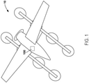
- Figure 1 is an example schematic view of an aircraft 10, according to an example.
- the aircraft 10 may be or include a fixed wing aircraft, a helicopter, a rotorcraft, an unmanned aerial vehicle (e.g., a drone or a satellite), a spacecraft, and the like.
- the aircraft 10 includes a navigation system 100, which further includes a computing system 150 that is described in more detail below.
- FIG. 2 is a schematic block diagram of the aircraft 10.
- the navigation system 100 includes a light source 102 (e.g., one or more lasers) and a light sensor 104 (e.g., one or more photodetectors or photosensors).
- the light source 102 and the light sensor 104 are operationally in communication with other components of the navigation system 100 and are generally part of a light detection and ranging system ( e.g. , LIDAR).
- the light source 102 and/or the light sensor 104 can be forward facing or rearward facing with respect to the aircraft 10, but other examples are possible.
- the navigation system 100 also includes control surfaces 182 and landing gear 184.
- the control surfaces 182 can include flaps, rudders, and ailerons, for example.
- the landing gear 184 includes one or more wheels that are motorized and can propel the aircraft 10 during ground travel, such as taxiing.
- the navigation system 100 also includes an inertial navigation system 190 which can create data 192.
- the inertial navigation system 190 can include one or more accelerometers and/or gyroscopes.
- Figure 3 is a schematic block diagram of the computing system 150.
- the computing system 150 includes one or more processors 152, a computer readable medium 154, a communication interface 156, a display 158, and a user interface 160. Components of the computing system 150 illustrated in Figure 3 are linked together by a system bus, network, or other connection mechanism 162.
- the computer readable medium 154 may be a non-transitory computer readable medium 154.
- the one or more processors 152 can be any type of processor(s), such as a microprocessor, a digital signal processor, a multicore processor, etc., coupled to the computer readable medium 154.
- the computer readable medium 154 can be any type of memory, such as volatile memory like random access memory (RAM), dynamic random access memory (DRAM), static random access memory (SRAM), or non-volatile memory like read-only memory (ROM), flash memory, magnetic or optical disks, or compact-disc read-only memory (CD-ROM), among other devices used to store data or programs on a temporary or permanent basis.
- volatile memory like random access memory (RAM), dynamic random access memory (DRAM), static random access memory (SRAM), or non-volatile memory like read-only memory (ROM), flash memory, magnetic or optical disks, or compact-disc read-only memory (CD-ROM), among other devices used to store data or programs on a temporary or permanent basis.
- RAM random access memory
- DRAM dynamic random access memory
- SRAM static random access memory
- ROM read-only memory
- flash memory magnetic or optical disks
- CD-ROM compact-disc read-only memory
- the computer readable medium 154 can be configured to store instructions 157.
- the instructions 157 are executable by the one or more processors 152 to cause the computing system 150 to perform any of the functions or methods described herein.
- the computer readable medium 154 also stores data 206.
- the data 206 includes a subset 210, a subset 216, and a subset 222 of the data 206, as described in more detail below.
- the communication interface 156 can include hardware to enable communication within the computing system 150 and/or between the computing system 150 and one or more other devices.
- the hardware can include transmitters, receivers, and antennas, for example.
- the communication interface 156 can be configured to facilitate communication with one or more other devices, in accordance with one or more wired or wireless communication protocols.
- the communication interface 156 can be configured to facilitate wireless data communication for the computing system 150 according to one or more wireless communication standards, such as one or more Institute of Electrical and Electronics Engineers (IEEE) 801.11 standards, ZigBee standards, Bluetooth standards, etc.
- IEEE Institute of Electrical and Electronics Engineers
- the communication interface 156 can be configured to facilitate wired data communication with one or more other devices.
- the display 158 can be any type of display component configured to display data.
- the display 158 can include a touchscreen display.
- the display 158 can include a flat-panel display, such as a liquid-crystal display (LCD) or a light-emitting diode (LED) display.
- LCD liquid-crystal display
- LED light-emitting diode
- the user interface 160 can include one or more pieces of hardware used to provide data and control signals to the computing system 150.
- the user interface 160 can include a mouse or a pointing device, a keyboard or a keypad, a microphone, a touchpad, or a touchscreen, among other possible types of user input devices.
- the user interface 160 can enable an operator to interact with a graphical user interface (GUI) provided by the computing system 150 ( e.g. , displayed by the display 158).
- GUI graphical user interface
- Figure 4 is a schematic diagram of the aircraft 10 positioned on a surface 202.
- a horizon 213 is pictured for clarity.
- the surface 202 can include combinations of many different types of surfaces such as runways, taxiways, or unpaved ground such as dirt or grass.
- the unpaved ground can help define borders of the runways or taxiways in that the unpaved ground is not considered part of the generally paved runways or taxiways.
- the light source 102 of the aircraft 10 is used to illuminate the surface 202 with a light 203 (e.g., a laser light) to cause a light 204 to be reflected from the surface 202.
- the light sensor 104 detects the light 204 that reflects from the surface 202.
- paved surfaces such as runways or taxiways return the light 204 with greater intensity than unpaved surfaces such as grass or dirt. Additionally, paved surfaces such as runways or taxiways will generally have a distinctive three-dimensional shape when compared to other surfaces.
- runway generally refers to a long and straight section of a (e.g. , paved) surface that is used for takeoff and/or landing.
- taxiway generally refers to a paved surface used by a taxiing aircraft to get from a hangar to a runway and vice versa.
- the light sensor 104 generates the data 206 representing the light 204.
- the data 206 maps intensities of the light 204 to respective positions on the surface 202.
- the data 206 includes a table that maps intensity values of the light 204 to respective sets of three-dimensional Cartesian or spherical coordinates.
- Figure 5A is a schematic diagram of the data 206 corresponding to the surface 202.
- the navigation system 100 identifies within the data 206 a subset 210 of the data 206 that corresponds to a border 212.
- the border 212 generally separates a second region 260 of paved surface on a first side of the border 212 from a first region 262 of unpaved surface on a second side of the border 212.
- the border 212 is a line, but a border can be a curved border that corresponds to an intersection or to a curved section of a runway or a taxiway as well.
- the border 212 can take on any shape and generally is any boundary that separates a runway or a taxiway from an unpaved surface.
- the subset 210 of the data 206 can be identified using statistical techniques as described below.
- a runway surface could be dirt or gravel and the non-runway surface could be grass.
- runway surfaces can be distinguished from non-runway surfaces by their differing (e.g. , painted) colors and resulting return intensity of the light 204.
- the non-runway surface can be paved as well.
- a runway surface can be distinguished from a non-runway surface because the light 204 returning from the runway surface will be different in intensity from the light 204 returning from the non-runway surface.
- the navigation system 100 selects an arbitrary data point 244 and an arbitrary data point 246 of the data 206 and determines parameters of a curve 248 (e.g., a line) that includes the arbitrary data point 244 and arbitrary data point 246.
- the curve 248 could be an arc of a circle, an arc of an ellipse, a parabola, a hyperbola, etc.
- the navigation system 100 determines that less than a threshold amount of data points of the data 206 conform to the curve 248 within a margin of error.
- the navigation system 100 could determine that less than ten data points of the data 206 conform to the curve 248 because less than ten residuals of the data 206 with respect to the curve 248 are less than a threshold amount. This process of searching for a curve fit for much of the data 206 can repeat until the navigation system 100 does find a curve that fits at least the threshold amount of data points of the data 206.
- the navigation system 100 selects an arbitrary data point 236 and an arbitrary data point 238 of the data 206 and determines parameters of a curve (e.g. , the border 212) that includes the arbitrary data point 236 and the arbitrary data point 238.
- the navigation system 100 determines that each data point of the subset 210 of the data 206 conforms to the curve (e.g., the border 212) within a margin of error and that the subset 210 of the data 206 includes at least a threshold amount of data points. That is, the navigation system 100 could determine that the subset 210 includes at least ten data points of the data 206, for example.
- the navigation system 100 can determine that the subset 210 of the data 206 includes at least a threshold amount of data points per unit distance along the curve (e.g., the border 212).
- the threshold amount of data points here could be ten data points per meter along the border 212, for example.
- the navigation system 100 can determine that the subset 210 of the data 206 has an average intensity of the light 204 that is greater than a threshold intensity that typically corresponds to a paved surface.
- the navigation system 100 determines parameters of a line that corresponds to the border 212 and determines that the region 262 of the surface 202 on one side of the line has an average intensity that is less than a first threshold intensity. Additionally, the navigation system 100 determines that the region 260 of the surface 202 on another side of the line has an average intensity that is greater than a second threshold intensity. In this way, the navigation system 100 can confirm that the border 212 in fact separates a paved region from an unpaved region, or more generally a runway region from a non-runway region.
- the navigation system 100 also identifies a subset 278 of the data 206 that does not correspond to a border and deletes, filters, or ignores the subset 278 of the data 206 so that it is not further processed.
- the navigation system 100 causes navigation of the aircraft 10 (e.g., during taxiing) based on a position of the border 212 indicated by the subset 210 of the data 206. For example, the navigation system 100 adjusts the control surfaces 182 and/or the landing gear 184 based on the position of the border 212 indicated by the subset 210 of the data 206. In one example, the aircraft 10 is controlled to maintain a minimum distance from the border 212. Navigation can also be aided by the data 192 collected by the inertial navigation system 190 of the aircraft 10.
- the navigation system 100 can also identify a subset 216 of the data 206 that corresponds to a border 218. In such examples, the navigation system 100 can cause navigation of the aircraft 10 additionally based on a position of the border 218 indicated by the subset 216 of the data 206. For example, the aircraft 10 could be controlled to stay substantially centered between the border 212 and the border 218. As shown in Figure 5A , the border 218 is substantially parallel to the border 212. Additionally, the border 212 could be on a first side of the aircraft 10 and the border 218 could be on a second side of the aircraft 10 that is opposite the first side.
- Figure 5B is a schematic diagram of a portion of the data 206 corresponding to the surface 202, with a more forward-looking perspective than Figure 5A .
- Figure 5B also includes a pictorial representation of an example runway, for the purpose of clarity.
- Figure 6 is a schematic diagram of the data 206 shown corresponding to the surface 202.
- a border 224 intersects both the border 212 and the border 218 to form a dead end.
- the navigation system 100 identifies a subset 222 of the data 206 that corresponds to the border 224 that intersects the border 212 and the border 218.
- the navigation system 100 causes navigation of the aircraft 10 additionally based on a position of the border 224 indicated by the subset 222 of the data 206. For example, upon encountering the dead end, the aircraft 10 is controlled to turn around or stop.
- Figure 7A is a schematic diagram of the data 206 shown mapped onto the surface 202.
- the border 212 intersects the border 218 to form a 90 degree corner at an intersection.
- Other examples include the border 212 forming a rounded corner with the border 218.
- the navigation system 100 determines an angle 230 at which the border 212 intersects the border 218 and a position of the angle 230.
- the navigation system 100 can cause navigation of the aircraft 10 additionally based on the angle (e.g., the value of the angle) and the position of the angle. That is, the aircraft 10 could make a 90 degree right turn after passing the border 218.
- the angle 230 could be 45 degrees and the aircraft 10 could make a 45 degree right turn at the angle 230.
- Figure 7B is a schematic diagram of the data 206 in an example in which runway surfaces form a four-way intersection.
- the navigation system 100 additionally determines that a subset 210B of the data 206 represents a border 212B, determines that a subset 216B of the data 206 represents a border 218B, and determines an angle 230B at which the border 212B intersects the border 218B and a position of the angle 230B.
- the navigation system 100 additionally determines that a subset 210C of the data 206 represents a border 212C, determines that a subset 216C of the data 206 represents a border 218C, and determines an angle 230C at which the border 212C intersects the border 218C and a position of the angle 230C.
- the navigation system 100 additionally determines that a subset 210D of the data 206 represents a border 212D, determines that a subset 216D of the data 206 represents a border 218D, and determines an angle 230D at which the border 212D intersects the border 218D and a position of the angle 230D.
- the navigation system 100 can cause navigation of the aircraft 10 additionally based on the angles 230, 230B, 230C, and/or 230D (e.g., the value of the angles) and the position of the angles 230, 230B, 230C, and/or 230D. That is, the aircraft 10 could make a 90 degree right turn after passing the border 218, upon recognizing the four-way intersection.
- the angles 230, 230B, 230C, and/or 230D e.g., the value of the angles
- the aircraft 10 could make a 90 degree right turn after passing the border 218, upon recognizing the four-way intersection.
- the navigation system 100 could look for a particular shape of intersection before executing a turn. For example, the aircraft 10 could be instructed to ignore a 45 degree turn that is encountered first and make a 90 degree right turn at the angle 230 thereafter in response to recognizing the 90 degree intersection of the border 212 and the border 218.
- Figures 8-13 are block diagrams of methods 300, 310, 314, 318, 322, and 326 for operating a navigation system of an aircraft.
- the methods 300, 310, 314, 318, 322, and 326 present examples of methods that could be used with the navigation system 100 as shown in Figures 1-7 .
- the methods 300, 310, 314, 318, 322, and 326 include one or more operations, functions, or actions as illustrated by blocks 302, 304, 306, 308, 312, 316, 320, 324, 328, and 330.
- the blocks are illustrated in a sequential order, these blocks may also be performed in parallel, and/or in a different order than those described herein.
- the various blocks may be combined into fewer blocks, divided into additional blocks, and/or removed based upon the desired implementation.
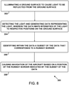
- Figure 8 is a block diagram of the method 300.
- the method 300 includes illuminating the surface 202 to cause the light 204 to be reflected from the surface 202.
- the light source 102 is used to illuminate the surface 202 with a light 203 (e.g., a laser light) to cause the light 204 to be reflected from the surface 202.
- a light 203 e.g., a laser light
- the method 300 includes detecting the light 204 and generating the data 206 representing the light 204.
- the data 206 maps intensities of the light 204 to respective positions 208 on the surface 202.
- the light sensor 104 detects the light 204 that reflects from the surface 202 and generates the data 206 representing the light 204.
- the data 206 maps intensities of the light 204 to respective positions on the surface 202.
- the data 206 includes a table that maps intensity values of the light 204 to respective sets of three-dimensional Cartesian or spherical coordinates. This functionality is described in more detail with reference to Figure 4 , Figure 5A , and Figure 5B above.
- the method 300 includes identifying within the data 206 the subset 210 of the data 206 that corresponds to the border 212.
- the navigation system 100 identifies within the data 206 the subset 210 of the data 206. This functionality is described in more detail with reference to Figure 5A and Figure 5B above.
- the method 300 includes causing navigation of the aircraft 10 based on a position of the border 212 indicated by the subset 210 of the data 206.
- the navigation system 100 causes navigation of the aircraft 10 based on the position of the border 212. This functionality is described in more detail with reference to Figures 5-7 above.
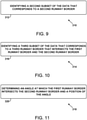
- Figure 9 is a block diagram of the method 310.
- the method 310 includes identifying the second subset 216 of the data 206 that corresponds to the second border 218. For example, the navigation system 100 identifies the second subset 216. This functionality is described in more detail with reference to Figure 5A and Figure 5B above.
- Figure 10 is a block diagram of the method 314.
- the method 314 includes identifying the third subset 222 of the data 206 that corresponds to the third border 224 that intersects the first border 212 and the second border 218. For example, the navigation system 100 identifies the third subset 222. This functionality is described in more detail with reference to Figure 6 above.
- Figure 11 is a block diagram of the method 318.
- the method 318 includes determining the angle 230 at which the first border 212 intersects the second border 218 and a position of the angle 230.
- the navigation system 100 determines the angle 230 and the position of the angle 230. This functionality is described in more detail with reference to Figure 7A and Figure 7B above.
- Figure 12 is a block diagram of the method 322.
- the method 322 includes determining that the first border 212 forms a particular shape with the second border 218.
- the navigation system 100 determines that the border 212 forms the particular shape with the second runway border 218. This functionality is described in more detail with reference to Figure 7A and Figure 7B above.
- Figure 13 is a block diagram of the method 326.
- the method 326 includes identifying the subset 278 of the data 206 that does not correspond to a border. For example, the navigation system 100 identifies the subset 278. This functionality is described in more detail with reference to Figure 5A and Figure 5B above.
- the method 326 includes deleting the subset 278 of the data 206.
- the navigation system 100 deletes the subset 278. This functionality is described in more detail with reference to Figure 5A and Figure 5B above.
Landscapes
- Engineering & Computer Science (AREA)
- Physics & Mathematics (AREA)
- Aviation & Aerospace Engineering (AREA)
- General Physics & Mathematics (AREA)
- Radar, Positioning & Navigation (AREA)
- Remote Sensing (AREA)
- Automation & Control Theory (AREA)
- Computer Networks & Wireless Communication (AREA)
- Electromagnetism (AREA)
- Traffic Control Systems (AREA)
- Navigation (AREA)
Abstract
Description
- The present disclosure generally relates to navigation systems and methods for operating them, and more specifically to aircraft navigation systems and methods for operating them.
- Autonomous aerial vehicles generally include some kind of autonomous navigation system to maneuver in the air or on the ground (e.g., during taxiing). Some conventional autonomous navigation techniques include using visible light cameras to capture successive images of a runway or another surface that the aircraft is taxiing on and analyzing each pixel of those images to identify runways or taxiways within those images. This can be very time intensive and computationally demanding. Additionally, such techniques can be less reliable in inclement weather such as rain or snow or in low light conditions. As such, a need exists for more efficient and environmentally resistant systems and methods for autonomous navigation of an aircraft on a ground surface.
- One aspect of the disclosure is a navigation system for an aircraft comprising: a light source; a light sensor; one or more processors; and a computer readable medium storing instructions that, when executed by the one or more processors, cause the navigation system to perform functions comprising: illuminating a surface using the light source to cause light to be reflected from the surface; detecting the light and generating data representing the light using the light sensor, wherein the data maps intensities of the light to respective positions on the surface; identifying within the data a subset of the data that corresponds to a border; and causing navigation of the aircraft based on a position of the border indicated by the subset of the data.
- Another aspect of the disclosure is a (optionally, non-transitory) computer readable medium storing instructions that, when executed by a navigation system of an aircraft, cause the navigation system to perform functions comprising: illuminating a surface to cause light to be reflected from the surface; detecting the light and generating data representing the light, wherein the data maps intensities of the light to respective positions on the surface; identifying within the data a subset of the data that corresponds to a border; and causing navigation of the aircraft based on a position of the border indicated by the subset of the data.
- Another aspect of the disclosure is a method of operating a navigation system of an aircraft, the method comprising: illuminating a surface to cause light to be reflected from the surface; detecting the light and generating data representing the light, wherein the data maps intensities of the light to respective positions on the surface; identifying within the data a subset of the data that corresponds to a border; and causing navigation of the aircraft based on a position of the border indicated by the subset of the data.
- By the term "about" or "substantially" with reference to amounts or measurement values described herein, it is meant that the recited characteristic, parameter, or value need not be achieved exactly, but that deviations or variations, including for example, tolerances, measurement error, measurement accuracy limitations and other factors known to those of skill in the art, may occur in amounts that do not preclude the effect the characteristic was intended to provide.
- The features, functions, and advantages that have been discussed can be achieved independently in various examples or may be combined in yet other examples further details of which can be seen with reference to the following description and drawings.
- The novel features believed characteristic of the illustrative examples are set forth in the appended claims. The illustrative examples, however, as well as a preferred mode of use, further objectives and descriptions thereof, will best be understood by reference to the following detailed description of an illustrative example of the present disclosure when read in conjunction with the accompanying Figures.
-
Figure 1 is a schematic diagram of an aircraft, according to an example. -
Figure 2 is a schematic block diagram of an aircraft, according to an example. -
Figure 3 is a schematic block diagram of a computing system, according to an example. -
Figure 4 is a schematic diagram of an aircraft positioned on a surface, according to an example. -
Figure 5A is a schematic diagram of data corresponding to a surface, according to an example. -
Figure 5B is a schematic diagram of data corresponding to a surface, according to an example. -
Figure 6 is a schematic diagram of data corresponding to a surface, according to an example. -
Figure 7A is a schematic diagram of data corresponding to a surface, according to an example. -
Figure 7B is a schematic diagram of data corresponding to a surface, according to an example. -
Figure 8 is a block diagram of a method, according to an example. -
Figure 9 is a block diagram of a method, according to an example. -
Figure 10 is a block diagram of a method, according to an example. -
Figure 11 is a block diagram of a method, according to an example. -
Figure 12 is a block diagram of a method, according to an example. -
Figure 13 is a block diagram of a method, according to an example. - As discussed above, a need exists for more efficient and environmentally resilient systems and methods for autonomous navigation of an aircraft on a surface (e.g., a ground surface). Within examples, a navigation system for an aircraft includes a light source, a light sensor, one or more processors, and a computer readable medium storing instructions that, when executed by the one or more processors, cause the navigation system to perform functions. The functions include illuminating a surface using the light source to cause light to be reflected from the surface and detecting the light and generating data representing the light using the light sensor. The data maps intensities of the light to respective positions on the surface. The functions further include identifying within the data a subset of the data that corresponds to a border between roadway and non-roadway, such as a runway border, and causing navigation of the aircraft based on a position of the border indicated by the subset of the data.
- The functionality of the aforementioned navigation system can yield better response time and more efficient use of computational resources when compared to conventional navigation systems, as explained in more detail below. Additionally, the disclosed navigation system can help improve performance in low light conditions and in inclement weather.
- Disclosed examples will now be described more fully hereinafter with reference to the accompanying Drawings, in which some, but not all of the disclosed examples are shown. Indeed, several different examples may be described and should not be construed as limited to the examples set forth herein. Rather, these examples are described so that this disclosure will be thorough and complete and will fully convey the scope of the disclosure to those skilled in the art.
-
Figures 1-7B are schematic diagrams of a navigation system and related functionality. -
Figure 1 is an example schematic view of anaircraft 10, according to an example. Theaircraft 10 may be or include a fixed wing aircraft, a helicopter, a rotorcraft, an unmanned aerial vehicle (e.g., a drone or a satellite), a spacecraft, and the like. Theaircraft 10 includes anavigation system 100, which further includes acomputing system 150 that is described in more detail below. -
Figure 2 is a schematic block diagram of theaircraft 10. Thenavigation system 100 includes a light source 102 (e.g., one or more lasers) and a light sensor 104 (e.g., one or more photodetectors or photosensors). Thelight source 102 and thelight sensor 104 are operationally in communication with other components of thenavigation system 100 and are generally part of a light detection and ranging system (e.g., LIDAR). Thelight source 102 and/or thelight sensor 104 can be forward facing or rearward facing with respect to theaircraft 10, but other examples are possible. - The
navigation system 100 also includescontrol surfaces 182 andlanding gear 184. Thecontrol surfaces 182 can include flaps, rudders, and ailerons, for example. Thelanding gear 184 includes one or more wheels that are motorized and can propel theaircraft 10 during ground travel, such as taxiing. - The
navigation system 100 also includes aninertial navigation system 190 which can createdata 192. Theinertial navigation system 190 can include one or more accelerometers and/or gyroscopes. -
Figure 3 is a schematic block diagram of thecomputing system 150. - The
computing system 150 includes one ormore processors 152, a computerreadable medium 154, acommunication interface 156, adisplay 158, and auser interface 160. Components of thecomputing system 150 illustrated inFigure 3 are linked together by a system bus, network, orother connection mechanism 162. The computerreadable medium 154 may be a non-transitory computerreadable medium 154. - The one or
more processors 152 can be any type of processor(s), such as a microprocessor, a digital signal processor, a multicore processor, etc., coupled to the computerreadable medium 154. - The computer
readable medium 154 can be any type of memory, such as volatile memory like random access memory (RAM), dynamic random access memory (DRAM), static random access memory (SRAM), or non-volatile memory like read-only memory (ROM), flash memory, magnetic or optical disks, or compact-disc read-only memory (CD-ROM), among other devices used to store data or programs on a temporary or permanent basis. - Additionally, the computer
readable medium 154 can be configured to storeinstructions 157. Theinstructions 157 are executable by the one ormore processors 152 to cause thecomputing system 150 to perform any of the functions or methods described herein. - The computer
readable medium 154 also storesdata 206. Thedata 206 includes asubset 210, asubset 216, and asubset 222 of thedata 206, as described in more detail below. - The
communication interface 156 can include hardware to enable communication within thecomputing system 150 and/or between thecomputing system 150 and one or more other devices. The hardware can include transmitters, receivers, and antennas, for example. Thecommunication interface 156 can be configured to facilitate communication with one or more other devices, in accordance with one or more wired or wireless communication protocols. For example, thecommunication interface 156 can be configured to facilitate wireless data communication for thecomputing system 150 according to one or more wireless communication standards, such as one or more Institute of Electrical and Electronics Engineers (IEEE) 801.11 standards, ZigBee standards, Bluetooth standards, etc. As another example, thecommunication interface 156 can be configured to facilitate wired data communication with one or more other devices. - The
display 158 can be any type of display component configured to display data. As one example, thedisplay 158 can include a touchscreen display. As another example, thedisplay 158 can include a flat-panel display, such as a liquid-crystal display (LCD) or a light-emitting diode (LED) display. - The
user interface 160 can include one or more pieces of hardware used to provide data and control signals to thecomputing system 150. For instance, theuser interface 160 can include a mouse or a pointing device, a keyboard or a keypad, a microphone, a touchpad, or a touchscreen, among other possible types of user input devices. Generally, theuser interface 160 can enable an operator to interact with a graphical user interface (GUI) provided by the computing system 150 (e.g., displayed by the display 158). -
Figure 4 is a schematic diagram of theaircraft 10 positioned on asurface 202. Ahorizon 213 is pictured for clarity. Thesurface 202 can include combinations of many different types of surfaces such as runways, taxiways, or unpaved ground such as dirt or grass. The unpaved ground can help define borders of the runways or taxiways in that the unpaved ground is not considered part of the generally paved runways or taxiways. - The
light source 102 of theaircraft 10 is used to illuminate thesurface 202 with a light 203 (e.g., a laser light) to cause a light 204 to be reflected from thesurface 202. Thelight sensor 104 detects the light 204 that reflects from thesurface 202. Generally, paved surfaces such as runways or taxiways return the light 204 with greater intensity than unpaved surfaces such as grass or dirt. Additionally, paved surfaces such as runways or taxiways will generally have a distinctive three-dimensional shape when compared to other surfaces. - It should be noted that the terms runway and taxiway are used somewhat interchangeably herein. However, the term runway generally refers to a long and straight section of a (e.g., paved) surface that is used for takeoff and/or landing. The term taxiway generally refers to a paved surface used by a taxiing aircraft to get from a hangar to a runway and vice versa.
- The
light sensor 104 generates thedata 206 representing the light 204. Thedata 206 maps intensities of the light 204 to respective positions on thesurface 202. For example, thedata 206 includes a table that maps intensity values of the light 204 to respective sets of three-dimensional Cartesian or spherical coordinates. -
Figure 5A is a schematic diagram of thedata 206 corresponding to thesurface 202. Thenavigation system 100 identifies within the data 206 asubset 210 of thedata 206 that corresponds to aborder 212. Theborder 212 generally separates asecond region 260 of paved surface on a first side of theborder 212 from afirst region 262 of unpaved surface on a second side of theborder 212. InFigure 5A , theborder 212 is a line, but a border can be a curved border that corresponds to an intersection or to a curved section of a runway or a taxiway as well. Theborder 212 can take on any shape and generally is any boundary that separates a runway or a taxiway from an unpaved surface. Thesubset 210 of thedata 206 can be identified using statistical techniques as described below. - In other examples, a runway surface could be dirt or gravel and the non-runway surface could be grass. In yet other examples, runway surfaces can be distinguished from non-runway surfaces by their differing (e.g., painted) colors and resulting return intensity of the light 204. In yet further examples, the non-runway surface can be paved as well. Generally, a runway surface can be distinguished from a non-runway surface because the light 204 returning from the runway surface will be different in intensity from the light 204 returning from the non-runway surface.
- The navigation system 100 (e.g., randomly) selects an
arbitrary data point 244 and anarbitrary data point 246 of thedata 206 and determines parameters of a curve 248 (e.g., a line) that includes thearbitrary data point 244 andarbitrary data point 246. The parameters could take the form of a, b, and c in the equation z=ax+by+c, for example. In other examples, thecurve 248 could be an arc of a circle, an arc of an ellipse, a parabola, a hyperbola, etc. Next, thenavigation system 100 determines that less than a threshold amount of data points of thedata 206 conform to thecurve 248 within a margin of error. For example, thenavigation system 100 could determine that less than ten data points of thedata 206 conform to thecurve 248 because less than ten residuals of thedata 206 with respect to thecurve 248 are less than a threshold amount. This process of searching for a curve fit for much of thedata 206 can repeat until thenavigation system 100 does find a curve that fits at least the threshold amount of data points of thedata 206. - For example, the navigation system 100 (e.g, randomly) selects an
arbitrary data point 236 and anarbitrary data point 238 of thedata 206 and determines parameters of a curve (e.g., the border 212) that includes thearbitrary data point 236 and thearbitrary data point 238. Next, thenavigation system 100 determines that each data point of thesubset 210 of thedata 206 conforms to the curve (e.g., the border 212) within a margin of error and that thesubset 210 of thedata 206 includes at least a threshold amount of data points. That is, thenavigation system 100 could determine that thesubset 210 includes at least ten data points of thedata 206, for example. - To additionally confirm a good fit to the curve, the
navigation system 100 can determine that thesubset 210 of thedata 206 includes at least a threshold amount of data points per unit distance along the curve (e.g., the border 212). The threshold amount of data points here could be ten data points per meter along theborder 212, for example. - To add additional confidence that the
border 212 is, in fact, a border, thenavigation system 100 can determine that thesubset 210 of thedata 206 has an average intensity of the light 204 that is greater than a threshold intensity that typically corresponds to a paved surface. - In some examples, the
navigation system 100 determines parameters of a line that corresponds to theborder 212 and determines that theregion 262 of thesurface 202 on one side of the line has an average intensity that is less than a first threshold intensity. Additionally, thenavigation system 100 determines that theregion 260 of thesurface 202 on another side of the line has an average intensity that is greater than a second threshold intensity. In this way, thenavigation system 100 can confirm that theborder 212 in fact separates a paved region from an unpaved region, or more generally a runway region from a non-runway region. - In some examples, the
navigation system 100 also identifies asubset 278 of thedata 206 that does not correspond to a border and deletes, filters, or ignores thesubset 278 of thedata 206 so that it is not further processed. - Additionally, the
navigation system 100 causes navigation of the aircraft 10 (e.g., during taxiing) based on a position of theborder 212 indicated by thesubset 210 of thedata 206. For example, thenavigation system 100 adjusts thecontrol surfaces 182 and/or thelanding gear 184 based on the position of theborder 212 indicated by thesubset 210 of thedata 206. In one example, theaircraft 10 is controlled to maintain a minimum distance from theborder 212. Navigation can also be aided by thedata 192 collected by theinertial navigation system 190 of theaircraft 10. - The
navigation system 100 can also identify asubset 216 of thedata 206 that corresponds to aborder 218. In such examples, thenavigation system 100 can cause navigation of theaircraft 10 additionally based on a position of theborder 218 indicated by thesubset 216 of thedata 206. For example, theaircraft 10 could be controlled to stay substantially centered between theborder 212 and theborder 218. As shown inFigure 5A , theborder 218 is substantially parallel to theborder 212. Additionally, theborder 212 could be on a first side of theaircraft 10 and theborder 218 could be on a second side of theaircraft 10 that is opposite the first side. -
Figure 5B is a schematic diagram of a portion of thedata 206 corresponding to thesurface 202, with a more forward-looking perspective thanFigure 5A .Figure 5B also includes a pictorial representation of an example runway, for the purpose of clarity. -
Figure 6 is a schematic diagram of thedata 206 shown corresponding to thesurface 202. In this example, aborder 224 intersects both theborder 212 and theborder 218 to form a dead end. As such, thenavigation system 100 identifies asubset 222 of thedata 206 that corresponds to theborder 224 that intersects theborder 212 and theborder 218. In this context, thenavigation system 100 causes navigation of theaircraft 10 additionally based on a position of theborder 224 indicated by thesubset 222 of thedata 206. For example, upon encountering the dead end, theaircraft 10 is controlled to turn around or stop. -
Figure 7A is a schematic diagram of thedata 206 shown mapped onto thesurface 202. In this example, theborder 212 intersects theborder 218 to form a 90 degree corner at an intersection. Other examples include theborder 212 forming a rounded corner with theborder 218. - As such, the
navigation system 100 determines anangle 230 at which theborder 212 intersects theborder 218 and a position of theangle 230. In this context, thenavigation system 100 can cause navigation of theaircraft 10 additionally based on the angle (e.g., the value of the angle) and the position of the angle. That is, theaircraft 10 could make a 90 degree right turn after passing theborder 218. In another example, theangle 230 could be 45 degrees and theaircraft 10 could make a 45 degree right turn at theangle 230. -
Figure 7B is a schematic diagram of thedata 206 in an example in which runway surfaces form a four-way intersection. Thenavigation system 100 additionally determines that asubset 210B of thedata 206 represents aborder 212B, determines that asubset 216B of thedata 206 represents a border 218B, and determines an angle 230B at which theborder 212B intersects the border 218B and a position of the angle 230B. Thenavigation system 100 additionally determines that asubset 210C of thedata 206 represents aborder 212C, determines that asubset 216C of thedata 206 represents a border 218C, and determines anangle 230C at which theborder 212C intersects the border 218C and a position of theangle 230C. Thenavigation system 100 additionally determines that asubset 210D of thedata 206 represents aborder 212D, determines that asubset 216D of thedata 206 represents a border 218D, and determines anangle 230D at which theborder 212D intersects the border 218D and a position of theangle 230D. - In this context, the
navigation system 100 can cause navigation of theaircraft 10 additionally based on theangles angles aircraft 10 could make a 90 degree right turn after passing theborder 218, upon recognizing the four-way intersection. - In some examples, the
navigation system 100 could look for a particular shape of intersection before executing a turn. For example, theaircraft 10 could be instructed to ignore a 45 degree turn that is encountered first and make a 90 degree right turn at theangle 230 thereafter in response to recognizing the 90 degree intersection of theborder 212 and theborder 218. -
Figures 8-13 are block diagrams ofmethods methods navigation system 100 as shown inFigures 1-7 . As shown inFigures 8-13 , themethods blocks -
Figure 8 is a block diagram of themethod 300. - At
block 302, themethod 300 includes illuminating thesurface 202 to cause the light 204 to be reflected from thesurface 202. For example, thelight source 102 is used to illuminate thesurface 202 with a light 203 (e.g., a laser light) to cause the light 204 to be reflected from thesurface 202. This functionality is described in more detail with reference toFigure 4 above. - At
block 304, themethod 300 includes detecting the light 204 and generating thedata 206 representing the light 204. Thedata 206 maps intensities of the light 204 torespective positions 208 on thesurface 202. For example, thelight sensor 104 detects the light 204 that reflects from thesurface 202 and generates thedata 206 representing the light 204. Thedata 206 maps intensities of the light 204 to respective positions on thesurface 202. For example, thedata 206 includes a table that maps intensity values of the light 204 to respective sets of three-dimensional Cartesian or spherical coordinates. This functionality is described in more detail with reference toFigure 4 ,Figure 5A , andFigure 5B above. - At
block 306, themethod 300 includes identifying within thedata 206 thesubset 210 of thedata 206 that corresponds to theborder 212. For example, thenavigation system 100 identifies within thedata 206 thesubset 210 of thedata 206. This functionality is described in more detail with reference toFigure 5A andFigure 5B above. - At
block 308, themethod 300 includes causing navigation of theaircraft 10 based on a position of theborder 212 indicated by thesubset 210 of thedata 206. For example, thenavigation system 100 causes navigation of theaircraft 10 based on the position of theborder 212. This functionality is described in more detail with reference toFigures 5-7 above. -
Figure 9 is a block diagram of themethod 310. - At
block 312, themethod 310 includes identifying thesecond subset 216 of thedata 206 that corresponds to thesecond border 218. For example, thenavigation system 100 identifies thesecond subset 216. This functionality is described in more detail with reference toFigure 5A andFigure 5B above. -
Figure 10 is a block diagram of themethod 314. - At
block 316, themethod 314 includes identifying thethird subset 222 of thedata 206 that corresponds to thethird border 224 that intersects thefirst border 212 and thesecond border 218. For example, thenavigation system 100 identifies thethird subset 222. This functionality is described in more detail with reference toFigure 6 above. -
Figure 11 is a block diagram of themethod 318. - At
block 320, themethod 318 includes determining theangle 230 at which thefirst border 212 intersects thesecond border 218 and a position of theangle 230. For example, thenavigation system 100 determines theangle 230 and the position of theangle 230. This functionality is described in more detail with reference toFigure 7A andFigure 7B above. -
Figure 12 is a block diagram of themethod 322. - At
block 324, themethod 322 includes determining that thefirst border 212 forms a particular shape with thesecond border 218. For example, thenavigation system 100 determines that theborder 212 forms the particular shape with thesecond runway border 218. This functionality is described in more detail with reference toFigure 7A andFigure 7B above. -
Figure 13 is a block diagram of themethod 326. - At
block 328, themethod 326 includes identifying thesubset 278 of thedata 206 that does not correspond to a border. For example, thenavigation system 100 identifies thesubset 278. This functionality is described in more detail with reference toFigure 5A andFigure 5B above. - At
block 330, themethod 326 includes deleting thesubset 278 of thedata 206. For example, thenavigation system 100 deletes thesubset 278. This functionality is described in more detail with reference toFigure 5A andFigure 5B above. - Examples of the present disclosure can thus relate to one of the enumerated clauses (ECs) listed below. While the scope of protection is determined by the appended claims, realizations of the present disclosure can be made in many ways including, but not limited to, those according to the following enumerated clauses:
- EC 1 is a navigation system for an aircraft comprising: a light source; a light sensor; one or more processors; and a computer readable medium storing instructions that, when executed by the one or more processors, cause the navigation system to perform functions comprising: illuminating a surface using the light source to cause light to be reflected from the surface; detecting the light and generating data representing the light using the light sensor, wherein the data maps intensities of the light to respective positions on the surface; identifying within the data a subset of the data that corresponds to a border; and causing navigation of the aircraft based on a position of the border indicated by the subset of the data.
- EC 2 is the navigation system of EC 1, wherein the border is a first border, the functions further comprising: identifying a second subset of the data that corresponds to a second border, wherein causing navigation of the aircraft comprises causing navigation of the aircraft additionally based on a second position of the second border indicated by the second subset of the data.
- EC 3 is the navigation system of EC 2, wherein the second border is substantially parallel to the first border.
- EC 4 is the navigation system of EC 2 or EC 3, the functions further comprising: identifying a third subset of the data that corresponds to a third border that intersects the first border and the second border, wherein causing navigation of the aircraft comprises causing navigation of the aircraft additionally based on a third position of the third border indicated by the third subset of the data.
- EC 5 is the navigation system of any of ECs 2-4, wherein the first border is on a first side of the aircraft and the second border is on a second side of the aircraft that is opposite the first side.
- EC 6 is the navigation system of any of ECs 2, 4 or 5, wherein the first border intersects the second border.
- EC 7 is the navigation system of EC 6, the functions further comprising: determining an angle at which the first border intersects the second border and a position of the angle, wherein causing navigation of the aircraft comprises causing navigation of the aircraft additionally based on the position and the angle.
- EC 8 is the navigation system of any of ECs 2-7, the functions further comprising: determining that the first border forms a particular shape with the second border, wherein causing navigation of the aircraft comprises causing navigation of the aircraft additionally based on determining that the first border forms the particular shape with the second border.
- EC 9 is the navigation system of any of ECs 1-8, wherein causing navigation of the aircraft comprises causing navigation of the aircraft on the surface.
-
EC 10 is the navigation system of any of ECs 1-9, wherein identifying the subset of the data comprises: selecting two arbitrary data points of the data; determining parameters of a shape that includes the two arbitrary data points; and determining that each data point of the subset of the data conforms to the shape within a margin of error and that the subset of the data includes at least a threshold amount of data points. - EC 11 is the navigation system of
EC 10, wherein identifying the subset of the data further comprises: selecting a second two arbitrary data points of the data; determining parameters of a second curve that includes the second two arbitrary data points; and determining that less than the threshold amount of data points of the data conform to the second curve within the margin of error. - EC 12 is the navigation system of any of ECs 10-11, wherein identifying the subset of the data further comprises determining that the subset of the data includes at least a second threshold amount of data points per unit distance.
- EC 13 is the navigation system of any of ECs 10-12, wherein identifying the subset of the data further comprises determining that the subset of the data has an average intensity that is greater than a threshold intensity.
- EC 14 is the navigation system of any of ECs 1-13, wherein causing navigation of the aircraft comprises causing navigation of the aircraft additionally based on data collected by an inertial navigation system of the aircraft.
- EC 15 is the navigation system of any of ECs 1-14, wherein identifying the subset of the data comprises: determining parameters of a line that corresponds to the border; determining that a first region of the surface on a first side of the line has a first average intensity that is less than a first threshold intensity; and determining that a second region of the surface on a second side of the line has a second average intensity that is greater than a second threshold intensity.
- EC 16 is the navigation system of any of ECs 1-15, wherein causing navigation of the aircraft comprises adjusting a control surface or landing gear of the aircraft based on the position of the border indicated by the subset of the data.
- EC 17 is the navigation system of any of ECs 1-16, wherein the subset is a first subset, the functions further comprising: identifying a second subset of the data that does not correspond to a border; and deleting the second subset of the data.
- EC 17a is a method of operating the navigation system of any of EC 1-17.
- EC 17b is the method of EC 17a, comprising the steps of EC 19 or 20.
- EC 18 is a computer readable medium storing instructions that, when executed by a navigation system of an aircraft, cause the navigation system to perform functions comprising: illuminating a surface to cause light to be reflected from the surface; detecting the light and generating data representing the light, wherein the data maps intensities of the light to respective positions on the surface; identifying within the data a subset of the data that corresponds to a border; and causing navigation of the aircraft based on a position of the border indicated by the subset of the data. The computer readable medium may be a non-transitory computer readable medium.
- EC 19 is a method of operating a navigation system of an aircraft, the method comprising: illuminating a surface to cause light to be reflected from the surface; detecting the light and generating data representing the light, wherein the data maps intensities of the light to respective positions on the surface; identifying within the data a subset of the data that corresponds to a border; and causing navigation of the aircraft based on a position of the border indicated by the subset of the data.
- EC 20 is the method of EC 19, wherein identifying the subset of the data comprises: selecting two arbitrary data points of the data; determining parameters of a curve that includes the two arbitrary data points; and determining that each data point of the subset of the data conforms to the curve within a margin of error and that the subset of the data includes at least a threshold amount of data points.
- EC 21 is the method of EC 19 or 20, carried out using the system of any of EC 1-17.
- The disclosure comprises the subject matter described in the above clauses.
- The description of the different advantageous arrangements has been presented for purposes of illustration and description, and is not intended to be exhaustive or limited to the examples in the form disclosed. Many modifications and variations will be apparent to those of ordinary skill in the art. Further, different advantageous examples may describe different advantages as compared to other advantageous examples. The example or examples selected are chosen and described in order to explain the principles of the examples, the practical application, and to enable others of ordinary skill in the art to understand the disclosure for various examples with various modifications as are suited to the particular use contemplated.
Claims (15)
- A navigation system (100) for an aircraft (10) comprising:a light source (102);a light sensor (104);one or more processors (152); anda computer readable medium (154) storing instructions (157) that, when executed by the one or more processors, cause the navigation system to perform functions comprising:illuminating a surface (202) using the light source to cause light (204) to be reflected from the surface;detecting the light and generating data (206) representing the light using the light sensor, wherein the data maps intensities of the light to respective positions (208) on the surface;identifying within the data a subset (210) of the data that corresponds to a border (212); andcausing navigation of the aircraft based on a position of the border indicated by the subset of the data.
- The navigation system of claim 1, wherein the border is a first border, the functions further comprising:identifying (312) a second subset (216) of the data that corresponds to a second border (218),and wherein causing navigation of the aircraft comprises causing navigation of the aircraft additionally based on a second position of the second border indicated by the second subset of the data.
- The navigation system of claim 2, wherein the second border is substantially parallel to the first border.
- The navigation system of claim 2 or 3, the functions further comprising:identifying (316) a third subset (222) of the data that corresponds to a third border (224) that intersects the first border and the second border,and wherein causing navigation of the aircraft comprises causing navigation of the aircraft additionally based on a third position of the third border indicated by the third subset of the data.
- The navigation system of any of claims 2-4, wherein the first border is on a first side of the aircraft and the second border is on a second side of the aircraft that is opposite the first side.
- The navigation system of claim 2, 4 or 5, wherein the first border intersects the second border.
- The navigation system of claim 6, the functions further comprising:determining (320) an angle (230) at which the first border intersects the second border and a position of the angle,and wherein causing navigation of the aircraft comprises causing navigation of the aircraft additionally based on the position and the angle.
- The navigation system of any of claims 2-7, the functions further comprising:
(324) determining that the first border forms a particular shape with the second border, wherein causing navigation of the aircraft comprises causing navigation of the aircraft additionally based on determining that the first border forms the particular shape with the second border. - The navigation system of any of claims 1-8, wherein causing navigation of the aircraft comprises causing navigation of the aircraft on the surface.
- The navigation system of any of claims 1-9, wherein identifying the subset of the data comprises:selecting two arbitrary data points (236, 238) of the data;determining parameters of a curve that includes the two arbitrary data points; anddetermining that each data point of the subset of the data conforms to the shape within a margin of error and that the subset of the data includes at least a threshold amount of data points.
- The navigation system of any of claims 1-10, wherein identifying the subset of the data comprises:determining parameters of a line that corresponds to the border;determining that a first region (262) of the surface on a first side of the line has a first average intensity that is less than a first threshold intensity; anddetermining that a second region (260) of the surface on a second side of the line has a second average intensity that is greater than a second threshold intensity.
- The navigation system of any of claims 1-11, wherein causing navigation of the aircraft comprises adjusting a control surface (182) or landing gear (184) of the aircraft based on the position of the border indicated by the subset of the data.
- The navigation system of any of claims 1-12, wherein the subset is a first subset, the functions further comprising:identifying (328) a second subset (278) of the data that does not correspond to a border; anddeleting (330) the second subset of the data.
- A method (300) of operating a navigation system (100) of an aircraft (10), the method comprising:illuminating (302) a surface (202) to cause light (204) to be reflected from the surface;detecting (304) the light and generating data (206) representing the light, wherein the data maps intensities of the light to respective positions (208) on the surface;identifying (306) within the data a subset (210) of the data that corresponds to a border (212); andcausing (308) navigation of the aircraft based on a position of the border indicated by the subset of the data.
- The method of claim 14, wherein identifying the subset of the data comprises:selecting two arbitrary data points (236, 238) of the data;determining parameters of a curve that includes the two arbitrary data points; anddetermining that each data point of the subset of the data conforms to the curve within a margin of error and that the subset of the data includes at least a threshold amount of data points.
Applications Claiming Priority (2)
| Application Number | Priority Date | Filing Date | Title |
|---|---|---|---|
| US202063068132P | 2020-08-20 | 2020-08-20 | |
| US17/360,828 US12307910B2 (en) | 2020-08-20 | 2021-06-28 | Navigation systems and methods for operation |
Publications (2)
| Publication Number | Publication Date |
|---|---|
| EP3958237A1 true EP3958237A1 (en) | 2022-02-23 |
| EP3958237B1 EP3958237B1 (en) | 2025-10-08 |
Family
ID=77626924
Family Applications (1)
| Application Number | Title | Priority Date | Filing Date |
|---|---|---|---|
| EP21191779.4A Active EP3958237B1 (en) | 2020-08-20 | 2021-08-17 | Navigation systems and methods for operation |
Country Status (2)
| Country | Link |
|---|---|
| US (2) | US12307910B2 (en) |
| EP (1) | EP3958237B1 (en) |
Citations (4)
| Publication number | Priority date | Publication date | Assignee | Title |
|---|---|---|---|---|
| US20100039294A1 (en) * | 2008-08-14 | 2010-02-18 | Honeywell International Inc. | Automated landing area detection for aircraft |
| KR100985195B1 (en) * | 2010-01-21 | 2010-10-05 | 한국항공우주산업 주식회사 | System for automatic taking off and landing of image based |
| US20150170526A1 (en) * | 2013-12-13 | 2015-06-18 | Sikorsky Aircraft Corporation | Semantics based safe landing area detection for an unmanned vehicle |
| US20170283087A1 (en) * | 2016-03-31 | 2017-10-05 | Sikorsky Aircraft Corporation | Sensor-based detection of landing zones |
Family Cites Families (9)
| Publication number | Priority date | Publication date | Assignee | Title |
|---|---|---|---|---|
| FR2835314B1 (en) * | 2002-01-25 | 2004-04-30 | Airbus France | METHOD FOR GUIDING AN AIRCRAFT IN THE FINAL LANDING PHASE AND CORRESPONDING DEVICE |
| US8868345B2 (en) * | 2011-06-30 | 2014-10-21 | General Electric Company | Meteorological modeling along an aircraft trajectory |
| CN102682292B (en) | 2012-05-10 | 2014-01-29 | 清华大学 | Method based on monocular vision for detecting and roughly positioning edge of road |
| US10029804B1 (en) * | 2015-05-14 | 2018-07-24 | Near Earth Autonomy, Inc. | On-board, computerized landing zone evaluation system for aircraft |
| CN106225723B (en) | 2016-07-25 | 2019-03-29 | 浙江零跑科技有限公司 | A kind of hinged angle measuring method of multiple row vehicle based on backsight binocular camera |
| US11415661B2 (en) * | 2016-11-17 | 2022-08-16 | Trinamix Gmbh | Detector for optically detecting at least one object |
| EP3483629B1 (en) | 2017-11-09 | 2021-12-29 | Veoneer Sweden AB | Detecting a parking row with a vehicle radar system |
| US10878709B2 (en) * | 2018-07-19 | 2020-12-29 | The Boeing Company | System, method, and computer readable medium for autonomous airport runway navigation |
| CN110142805A (en) | 2019-05-22 | 2019-08-20 | 武汉爱速达机器人科技有限公司 | A kind of robot end's calibration method based on laser radar |
-
2021
- 2021-06-28 US US17/360,828 patent/US12307910B2/en active Active
- 2021-08-17 EP EP21191779.4A patent/EP3958237B1/en active Active
-
2025
- 2025-03-24 US US19/087,837 patent/US20250252856A1/en active Pending
Patent Citations (4)
| Publication number | Priority date | Publication date | Assignee | Title |
|---|---|---|---|---|
| US20100039294A1 (en) * | 2008-08-14 | 2010-02-18 | Honeywell International Inc. | Automated landing area detection for aircraft |
| KR100985195B1 (en) * | 2010-01-21 | 2010-10-05 | 한국항공우주산업 주식회사 | System for automatic taking off and landing of image based |
| US20150170526A1 (en) * | 2013-12-13 | 2015-06-18 | Sikorsky Aircraft Corporation | Semantics based safe landing area detection for an unmanned vehicle |
| US20170283087A1 (en) * | 2016-03-31 | 2017-10-05 | Sikorsky Aircraft Corporation | Sensor-based detection of landing zones |
Also Published As
| Publication number | Publication date |
|---|---|
| US20250252856A1 (en) | 2025-08-07 |
| US12307910B2 (en) | 2025-05-20 |
| EP3958237B1 (en) | 2025-10-08 |
| US20220058962A1 (en) | 2022-02-24 |
Similar Documents
| Publication | Publication Date | Title |
|---|---|---|
| CN113359782B (en) | Unmanned aerial vehicle autonomous addressing landing method integrating LIDAR point cloud and image data | |
| US9070285B1 (en) | Passive camera based cloud detection and avoidance for aircraft systems | |
| CN112378397B (en) | Unmanned aerial vehicle target tracking method and device and unmanned aerial vehicle | |
| CN105865454B (en) | A kind of Navigation of Pilotless Aircraft method generated based on real-time online map | |
| US20190147320A1 (en) | "Matching Adversarial Networks" | |
| CN103822635B (en) | The unmanned plane during flying spatial location real-time computing technique of view-based access control model information | |
| Turk et al. | Video road-following for the autonomous land vehicle | |
| CN108820233B (en) | Visual landing guiding method for fixed-wing unmanned aerial vehicle | |
| CN112379681B (en) | Unmanned aerial vehicle obstacle avoidance flight method and device and unmanned aerial vehicle | |
| CN112596071B (en) | Unmanned aerial vehicle autonomous positioning method and device and unmanned aerial vehicle | |
| US20100305857A1 (en) | Method and System for Visual Collision Detection and Estimation | |
| US20160027314A1 (en) | Context-aware landing zone classification | |
| CN112380933B (en) | Unmanned aerial vehicle target recognition method and device and unmanned aerial vehicle | |
| CN105318888A (en) | Unmanned perception based unmanned aerial vehicle route planning method | |
| CN103809598A (en) | Rotor unmanned aircraft independent take-off and landing system based on three-layer triangle multi-color landing ground | |
| US20100231418A1 (en) | Methods and systems for correlating data sources for vehicle displays | |
| CN111413708A (en) | Lidar-based UAV autonomous identification and landing site selection method | |
| CN106200672A (en) | A kind of unmanned plane barrier-avoiding method based on light stream | |
| CN110187716A (en) | Geological survey unmanned aerial vehicle flight control method and device | |
| Dolph et al. | Sense and avoid for small unmanned aircraft systems | |
| CN120070580B (en) | Docking positioning method between tractor and aircraft wheel, tractor and medium | |
| EP3958237B1 (en) | Navigation systems and methods for operation | |
| Gong et al. | A survey of techniques for detection and tracking of airport runways | |
| CN115097846B (en) | Unmanned vehicle and unmanned vehicle cooperative landing method and system | |
| Herath et al. | AI-Driven Landing Zone Detection Module for Vertical Take-Off and Landing Vehicles using Projection-Based LiDAR-Navigation Pipelines |
Legal Events
| Date | Code | Title | Description |
|---|---|---|---|
| PUAI | Public reference made under article 153(3) epc to a published international application that has entered the european phase |
Free format text: ORIGINAL CODE: 0009012 |
|
| STAA | Information on the status of an ep patent application or granted ep patent |
Free format text: STATUS: THE APPLICATION HAS BEEN PUBLISHED |
|
| AK | Designated contracting states |
Kind code of ref document: A1 Designated state(s): AL AT BE BG CH CY CZ DE DK EE ES FI FR GB GR HR HU IE IS IT LI LT LU LV MC MK MT NL NO PL PT RO RS SE SI SK SM TR |
|
| STAA | Information on the status of an ep patent application or granted ep patent |
Free format text: STATUS: REQUEST FOR EXAMINATION WAS MADE |
|
| 17P | Request for examination filed |
Effective date: 20220817 |
|
| RBV | Designated contracting states (corrected) |
Designated state(s): AL AT BE BG CH CY CZ DE DK EE ES FI FR GB GR HR HU IE IS IT LI LT LU LV MC MK MT NL NO PL PT RO RS SE SI SK SM TR |
|
| STAA | Information on the status of an ep patent application or granted ep patent |
Free format text: STATUS: EXAMINATION IS IN PROGRESS |
|
| 17Q | First examination report despatched |
Effective date: 20240612 |
|
| REG | Reference to a national code |
Ref country code: DE Ref legal event code: R079 Free format text: PREVIOUS MAIN CLASS: G08G0005000000 Ipc: G01S0013910000 Ref country code: DE Ref legal event code: R079 Ref document number: 602021039953 Country of ref document: DE Free format text: PREVIOUS MAIN CLASS: G08G0005000000 Ipc: G01S0013910000 |
|
| RIC1 | Information provided on ipc code assigned before grant |
Ipc: G05D 1/00 20060101ALI20250519BHEP Ipc: G01S 13/91 20060101AFI20250519BHEP |
|
| GRAP | Despatch of communication of intention to grant a patent |
Free format text: ORIGINAL CODE: EPIDOSNIGR1 |
|
| STAA | Information on the status of an ep patent application or granted ep patent |
Free format text: STATUS: GRANT OF PATENT IS INTENDED |
|
| INTG | Intention to grant announced |
Effective date: 20250722 |
|
| GRAS | Grant fee paid |
Free format text: ORIGINAL CODE: EPIDOSNIGR3 |
|
| GRAA | (expected) grant |
Free format text: ORIGINAL CODE: 0009210 |
|
| STAA | Information on the status of an ep patent application or granted ep patent |
Free format text: STATUS: THE PATENT HAS BEEN GRANTED |
|
| AK | Designated contracting states |
Kind code of ref document: B1 Designated state(s): AL AT BE BG CH CY CZ DE DK EE ES FI FR GB GR HR HU IE IS IT LI LT LU LV MC MK MT NL NO PL PT RO RS SE SI SK SM TR |
|
| REG | Reference to a national code |
Ref country code: GB Ref legal event code: FG4D Ref country code: CH Ref legal event code: F10 Free format text: ST27 STATUS EVENT CODE: U-0-0-F10-F00 (AS PROVIDED BY THE NATIONAL OFFICE) Effective date: 20251008 |
|
| REG | Reference to a national code |
Ref country code: DE Ref legal event code: R096 Ref document number: 602021039953 Country of ref document: DE |
|
| P01 | Opt-out of the competence of the unified patent court (upc) registered |
Free format text: CASE NUMBER: UPC_APP_8185_3958237/2025 Effective date: 20250929 |
|
| REG | Reference to a national code |
Ref country code: IE Ref legal event code: FG4D |
|
| REG | Reference to a national code |
Ref country code: NL Ref legal event code: MP Effective date: 20251008 |
|
| REG | Reference to a national code |
Ref country code: AT Ref legal event code: MK05 Ref document number: 1845245 Country of ref document: AT Kind code of ref document: T Effective date: 20251008 |
|
| PG25 | Lapsed in a contracting state [announced via postgrant information from national office to epo] |
Ref country code: NL Free format text: LAPSE BECAUSE OF FAILURE TO SUBMIT A TRANSLATION OF THE DESCRIPTION OR TO PAY THE FEE WITHIN THE PRESCRIBED TIME-LIMIT Effective date: 20251008 |
|
| PG25 | Lapsed in a contracting state [announced via postgrant information from national office to epo] |
Ref country code: ES Free format text: LAPSE BECAUSE OF FAILURE TO SUBMIT A TRANSLATION OF THE DESCRIPTION OR TO PAY THE FEE WITHIN THE PRESCRIBED TIME-LIMIT Effective date: 20251008 |
|
| REG | Reference to a national code |
Ref country code: LT Ref legal event code: MG9D |
|
| PG25 | Lapsed in a contracting state [announced via postgrant information from national office to epo] |
Ref country code: NO Free format text: LAPSE BECAUSE OF FAILURE TO SUBMIT A TRANSLATION OF THE DESCRIPTION OR TO PAY THE FEE WITHIN THE PRESCRIBED TIME-LIMIT Effective date: 20260108 |
|
| PG25 | Lapsed in a contracting state [announced via postgrant information from national office to epo] |
Ref country code: AT Free format text: LAPSE BECAUSE OF FAILURE TO SUBMIT A TRANSLATION OF THE DESCRIPTION OR TO PAY THE FEE WITHIN THE PRESCRIBED TIME-LIMIT Effective date: 20251008 Ref country code: FI Free format text: LAPSE BECAUSE OF FAILURE TO SUBMIT A TRANSLATION OF THE DESCRIPTION OR TO PAY THE FEE WITHIN THE PRESCRIBED TIME-LIMIT Effective date: 20251008 Ref country code: HR Free format text: LAPSE BECAUSE OF FAILURE TO SUBMIT A TRANSLATION OF THE DESCRIPTION OR TO PAY THE FEE WITHIN THE PRESCRIBED TIME-LIMIT Effective date: 20251008 |
|
| PG25 | Lapsed in a contracting state [announced via postgrant information from national office to epo] |
Ref country code: RS Free format text: LAPSE BECAUSE OF FAILURE TO SUBMIT A TRANSLATION OF THE DESCRIPTION OR TO PAY THE FEE WITHIN THE PRESCRIBED TIME-LIMIT Effective date: 20260108 |
|
| PG25 | Lapsed in a contracting state [announced via postgrant information from national office to epo] |
Ref country code: IS Free format text: LAPSE BECAUSE OF FAILURE TO SUBMIT A TRANSLATION OF THE DESCRIPTION OR TO PAY THE FEE WITHIN THE PRESCRIBED TIME-LIMIT Effective date: 20260208 |
|
| PG25 | Lapsed in a contracting state [announced via postgrant information from national office to epo] |
Ref country code: PT Free format text: LAPSE BECAUSE OF FAILURE TO SUBMIT A TRANSLATION OF THE DESCRIPTION OR TO PAY THE FEE WITHIN THE PRESCRIBED TIME-LIMIT Effective date: 20260209 |
|
| PG25 | Lapsed in a contracting state [announced via postgrant information from national office to epo] |
Ref country code: PL Free format text: LAPSE BECAUSE OF FAILURE TO SUBMIT A TRANSLATION OF THE DESCRIPTION OR TO PAY THE FEE WITHIN THE PRESCRIBED TIME-LIMIT Effective date: 20251008 |
|
| PG25 | Lapsed in a contracting state [announced via postgrant information from national office to epo] |
Ref country code: LV Free format text: LAPSE BECAUSE OF FAILURE TO SUBMIT A TRANSLATION OF THE DESCRIPTION OR TO PAY THE FEE WITHIN THE PRESCRIBED TIME-LIMIT Effective date: 20251008 |
|
| PG25 | Lapsed in a contracting state [announced via postgrant information from national office to epo] |
Ref country code: BG Free format text: LAPSE BECAUSE OF FAILURE TO SUBMIT A TRANSLATION OF THE DESCRIPTION OR TO PAY THE FEE WITHIN THE PRESCRIBED TIME-LIMIT Effective date: 20251008 |