EP3958023A1 - Display lens manufacturing apparatus and method, and head-mounted display device comprising display lens manufactured thereby - Google Patents
Display lens manufacturing apparatus and method, and head-mounted display device comprising display lens manufactured thereby Download PDFInfo
- Publication number
- EP3958023A1 EP3958023A1 EP20870015.3A EP20870015A EP3958023A1 EP 3958023 A1 EP3958023 A1 EP 3958023A1 EP 20870015 A EP20870015 A EP 20870015A EP 3958023 A1 EP3958023 A1 EP 3958023A1
- Authority
- EP
- European Patent Office
- Prior art keywords
- lens
- light
- laser light
- incident
- photosensitive substrate
- Prior art date
- Legal status (The legal status is an assumption and is not a legal conclusion. Google has not performed a legal analysis and makes no representation as to the accuracy of the status listed.)
- Pending
Links
- 238000000034 method Methods 0.000 title claims abstract description 31
- 238000004519 manufacturing process Methods 0.000 title claims abstract description 29
- 239000000758 substrate Substances 0.000 claims abstract description 61
- 230000003287 optical effect Effects 0.000 claims abstract description 60
- 239000000463 material Substances 0.000 claims abstract description 20
- 210000001747 pupil Anatomy 0.000 claims description 28
- 239000000853 adhesive Substances 0.000 claims description 3
- 230000001070 adhesive effect Effects 0.000 claims description 3
- 239000010408 film Substances 0.000 description 7
- 230000000694 effects Effects 0.000 description 4
- -1 silver halide Chemical class 0.000 description 4
- 230000003190 augmentative effect Effects 0.000 description 3
- 230000005540 biological transmission Effects 0.000 description 3
- 239000011521 glass Substances 0.000 description 3
- 229920002284 Cellulose triacetate Polymers 0.000 description 2
- 239000004952 Polyamide Substances 0.000 description 2
- 239000004698 Polyethylene Substances 0.000 description 2
- 239000004743 Polypropylene Substances 0.000 description 2
- NNLVGZFZQQXQNW-ADJNRHBOSA-N [(2r,3r,4s,5r,6s)-4,5-diacetyloxy-3-[(2s,3r,4s,5r,6r)-3,4,5-triacetyloxy-6-(acetyloxymethyl)oxan-2-yl]oxy-6-[(2r,3r,4s,5r,6s)-4,5,6-triacetyloxy-2-(acetyloxymethyl)oxan-3-yl]oxyoxan-2-yl]methyl acetate Chemical compound O([C@@H]1O[C@@H]([C@H]([C@H](OC(C)=O)[C@H]1OC(C)=O)O[C@H]1[C@@H]([C@@H](OC(C)=O)[C@H](OC(C)=O)[C@@H](COC(C)=O)O1)OC(C)=O)COC(=O)C)[C@@H]1[C@@H](COC(C)=O)O[C@@H](OC(C)=O)[C@H](OC(C)=O)[C@H]1OC(C)=O NNLVGZFZQQXQNW-ADJNRHBOSA-N 0.000 description 2
- 238000012937 correction Methods 0.000 description 2
- 230000003247 decreasing effect Effects 0.000 description 2
- 239000000839 emulsion Substances 0.000 description 2
- 229910052751 metal Inorganic materials 0.000 description 2
- 239000002184 metal Substances 0.000 description 2
- 238000012986 modification Methods 0.000 description 2
- 230000004048 modification Effects 0.000 description 2
- 229920003023 plastic Polymers 0.000 description 2
- 229920002647 polyamide Polymers 0.000 description 2
- 229920000573 polyethylene Polymers 0.000 description 2
- 229920000139 polyethylene terephthalate Polymers 0.000 description 2
- 239000005020 polyethylene terephthalate Substances 0.000 description 2
- 229920001155 polypropylene Polymers 0.000 description 2
- 238000000926 separation method Methods 0.000 description 2
- 108010010803 Gelatin Proteins 0.000 description 1
- 230000004075 alteration Effects 0.000 description 1
- 230000001427 coherent effect Effects 0.000 description 1
- 230000006866 deterioration Effects 0.000 description 1
- 229920000159 gelatin Polymers 0.000 description 1
- 239000008273 gelatin Substances 0.000 description 1
- 235000019322 gelatine Nutrition 0.000 description 1
- 235000011852 gelatine desserts Nutrition 0.000 description 1
- 239000004973 liquid crystal related substance Substances 0.000 description 1
- 239000005304 optical glass Substances 0.000 description 1
- 229920002120 photoresistant polymer Polymers 0.000 description 1
- 239000004033 plastic Substances 0.000 description 1
- 229920003217 poly(methylsilsesquioxane) Polymers 0.000 description 1
- 239000004417 polycarbonate Substances 0.000 description 1
- 229920000515 polycarbonate Polymers 0.000 description 1
- 239000002952 polymeric resin Substances 0.000 description 1
- 239000010453 quartz Substances 0.000 description 1
- VYPSYNLAJGMNEJ-UHFFFAOYSA-N silicon dioxide Inorganic materials O=[Si]=O VYPSYNLAJGMNEJ-UHFFFAOYSA-N 0.000 description 1
- 229910052709 silver Inorganic materials 0.000 description 1
- 239000004332 silver Substances 0.000 description 1
- 238000004088 simulation Methods 0.000 description 1
- 229920003002 synthetic resin Polymers 0.000 description 1
- 239000010409 thin film Substances 0.000 description 1
Images


Classifications
-
- G—PHYSICS
- G02—OPTICS
- G02B—OPTICAL ELEMENTS, SYSTEMS OR APPARATUS
- G02B27/00—Optical systems or apparatus not provided for by any of the groups G02B1/00 - G02B26/00, G02B30/00
- G02B27/01—Head-up displays
- G02B27/017—Head mounted
- G02B27/0172—Head mounted characterised by optical features
-
- G—PHYSICS
- G03—PHOTOGRAPHY; CINEMATOGRAPHY; ANALOGOUS TECHNIQUES USING WAVES OTHER THAN OPTICAL WAVES; ELECTROGRAPHY; HOLOGRAPHY
- G03H—HOLOGRAPHIC PROCESSES OR APPARATUS
- G03H1/00—Holographic processes or apparatus using light, infrared or ultraviolet waves for obtaining holograms or for obtaining an image from them; Details peculiar thereto
- G03H1/04—Processes or apparatus for producing holograms
- G03H1/0465—Particular recording light; Beam shape or geometry
-
- G—PHYSICS
- G02—OPTICS
- G02B—OPTICAL ELEMENTS, SYSTEMS OR APPARATUS
- G02B27/00—Optical systems or apparatus not provided for by any of the groups G02B1/00 - G02B26/00, G02B30/00
- G02B27/01—Head-up displays
- G02B27/0101—Head-up displays characterised by optical features
- G02B27/0103—Head-up displays characterised by optical features comprising holographic elements
-
- G—PHYSICS
- G02—OPTICS
- G02B—OPTICAL ELEMENTS, SYSTEMS OR APPARATUS
- G02B3/00—Simple or compound lenses
-
- G—PHYSICS
- G02—OPTICS
- G02B—OPTICAL ELEMENTS, SYSTEMS OR APPARATUS
- G02B3/00—Simple or compound lenses
- G02B3/0006—Arrays
- G02B3/0012—Arrays characterised by the manufacturing method
-
- G—PHYSICS
- G02—OPTICS
- G02B—OPTICAL ELEMENTS, SYSTEMS OR APPARATUS
- G02B5/00—Optical elements other than lenses
- G02B5/32—Holograms used as optical elements
-
- G—PHYSICS
- G03—PHOTOGRAPHY; CINEMATOGRAPHY; ANALOGOUS TECHNIQUES USING WAVES OTHER THAN OPTICAL WAVES; ELECTROGRAPHY; HOLOGRAPHY
- G03H—HOLOGRAPHIC PROCESSES OR APPARATUS
- G03H1/00—Holographic processes or apparatus using light, infrared or ultraviolet waves for obtaining holograms or for obtaining an image from them; Details peculiar thereto
- G03H1/0005—Adaptation of holography to specific applications
-
- G—PHYSICS
- G03—PHOTOGRAPHY; CINEMATOGRAPHY; ANALOGOUS TECHNIQUES USING WAVES OTHER THAN OPTICAL WAVES; ELECTROGRAPHY; HOLOGRAPHY
- G03H—HOLOGRAPHIC PROCESSES OR APPARATUS
- G03H1/00—Holographic processes or apparatus using light, infrared or ultraviolet waves for obtaining holograms or for obtaining an image from them; Details peculiar thereto
- G03H1/04—Processes or apparatus for producing holograms
-
- G—PHYSICS
- G03—PHOTOGRAPHY; CINEMATOGRAPHY; ANALOGOUS TECHNIQUES USING WAVES OTHER THAN OPTICAL WAVES; ELECTROGRAPHY; HOLOGRAPHY
- G03H—HOLOGRAPHIC PROCESSES OR APPARATUS
- G03H1/00—Holographic processes or apparatus using light, infrared or ultraviolet waves for obtaining holograms or for obtaining an image from them; Details peculiar thereto
- G03H1/04—Processes or apparatus for producing holograms
- G03H1/0402—Recording geometries or arrangements
- G03H1/041—Optical element in the object space affecting the object beam, not otherwise provided for
-
- G—PHYSICS
- G02—OPTICS
- G02B—OPTICAL ELEMENTS, SYSTEMS OR APPARATUS
- G02B27/00—Optical systems or apparatus not provided for by any of the groups G02B1/00 - G02B26/00, G02B30/00
- G02B27/01—Head-up displays
- G02B27/0101—Head-up displays characterised by optical features
- G02B27/0103—Head-up displays characterised by optical features comprising holographic elements
- G02B2027/0109—Head-up displays characterised by optical features comprising holographic elements comprising details concerning the making of holograms
-
- G—PHYSICS
- G02—OPTICS
- G02B—OPTICAL ELEMENTS, SYSTEMS OR APPARATUS
- G02B27/00—Optical systems or apparatus not provided for by any of the groups G02B1/00 - G02B26/00, G02B30/00
- G02B27/01—Head-up displays
- G02B27/017—Head mounted
- G02B27/0172—Head mounted characterised by optical features
- G02B2027/0174—Head mounted characterised by optical features holographic
-
- G—PHYSICS
- G03—PHOTOGRAPHY; CINEMATOGRAPHY; ANALOGOUS TECHNIQUES USING WAVES OTHER THAN OPTICAL WAVES; ELECTROGRAPHY; HOLOGRAPHY
- G03H—HOLOGRAPHIC PROCESSES OR APPARATUS
- G03H1/00—Holographic processes or apparatus using light, infrared or ultraviolet waves for obtaining holograms or for obtaining an image from them; Details peculiar thereto
- G03H1/04—Processes or apparatus for producing holograms
- G03H1/0402—Recording geometries or arrangements
- G03H2001/0415—Recording geometries or arrangements for recording reflection holograms
-
- G—PHYSICS
- G03—PHOTOGRAPHY; CINEMATOGRAPHY; ANALOGOUS TECHNIQUES USING WAVES OTHER THAN OPTICAL WAVES; ELECTROGRAPHY; HOLOGRAPHY
- G03H—HOLOGRAPHIC PROCESSES OR APPARATUS
- G03H1/00—Holographic processes or apparatus using light, infrared or ultraviolet waves for obtaining holograms or for obtaining an image from them; Details peculiar thereto
- G03H1/04—Processes or apparatus for producing holograms
- G03H1/0402—Recording geometries or arrangements
- G03H2001/0439—Recording geometries or arrangements for recording Holographic Optical Element [HOE]
-
- G—PHYSICS
- G03—PHOTOGRAPHY; CINEMATOGRAPHY; ANALOGOUS TECHNIQUES USING WAVES OTHER THAN OPTICAL WAVES; ELECTROGRAPHY; HOLOGRAPHY
- G03H—HOLOGRAPHIC PROCESSES OR APPARATUS
- G03H2223/00—Optical components
- G03H2223/12—Amplitude mask, e.g. diaphragm, Louver filter
-
- G—PHYSICS
- G03—PHOTOGRAPHY; CINEMATOGRAPHY; ANALOGOUS TECHNIQUES USING WAVES OTHER THAN OPTICAL WAVES; ELECTROGRAPHY; HOLOGRAPHY
- G03H—HOLOGRAPHIC PROCESSES OR APPARATUS
- G03H2223/00—Optical components
- G03H2223/19—Microoptic array, e.g. lens array
-
- G—PHYSICS
- G03—PHOTOGRAPHY; CINEMATOGRAPHY; ANALOGOUS TECHNIQUES USING WAVES OTHER THAN OPTICAL WAVES; ELECTROGRAPHY; HOLOGRAPHY
- G03H—HOLOGRAPHIC PROCESSES OR APPARATUS
- G03H2260/00—Recording materials or recording processes
- G03H2260/30—Details of photosensitive recording material not otherwise provided for
-
- G—PHYSICS
- G03—PHOTOGRAPHY; CINEMATOGRAPHY; ANALOGOUS TECHNIQUES USING WAVES OTHER THAN OPTICAL WAVES; ELECTROGRAPHY; HOLOGRAPHY
- G03H—HOLOGRAPHIC PROCESSES OR APPARATUS
- G03H2270/00—Substrate bearing the hologram
- G03H2270/55—Substrate bearing the hologram being an optical element, e.g. spectacles
Definitions
- the present disclosure claims priority to and the benefit of Korean Patent Application No. 10-2019-0120075 filed in the Korean Intellectual Property Office on September 27, 2019 , the entire contents of which are incorporated herein by reference.
- the present disclosure relates to a device for manufacturing a display lens, a method for manufacturing a display lens, and a head-mounted display device comprising display lens manufactured thereby.
- a display unit that implements AR, MR, or VR includes a diffractive light guide plate that uses a diffraction phenomenon based on a wave-like nature of light.
- a type that includes a plurality of diffractive optical elements with a plurality of relief grating patterns and a type that includes a transmission holographic optical element as a photosensitive material having an interference pattern recorded thereon are mainly used.
- Embodiments of the present disclosure intend to provide a device for manufacturing a display lens including a reflection holographic optical element for implementing a plurality of exit pupils, a method for manufacturing the display lens, and a head-mounted display device including the display lens manufactured thereby.
- An embodiment according to an aspect of the present disclosure provides a device for manufacturing a display lens including a holographic optical element formed by recording a hologram on a photosensitive substrate, in which a substrate is coated with a photosensitive material, through irradiation of laser beams, the device including: a first laser light incidence unit configured to cause first laser light, converging along an irradiation direction, to be incident on one surface of the photosensitive substrate; and a second laser light incidence unit configured to cause second laser light, diverging at a plurality of points along an irradiation direction, to be incident on the other surface of the photosensitive substrate.
- the second laser light incidence unit may include a lens array having one surface on which a plurality of lens portions configured to convert parallel light into diverging light are arranged, and parallel light incident on the lens array may be radiated as the second laser light, which is diverging light, toward the other surface of the photosensitive substrate at the plurality of points through the respective lens portions.
- a non-light-transmissive mask may be disposed around a region corresponding to each lens portion on a side of the lens array that is opposite to a side where the lens portions are arranged.
- a distance between centers of the lens portions may be 4 to 6 mm.
- a focal length of the lens portion may be 2 to 10 mm.
- a diameter of the lens portion may be 1 to 3 mm.
- An embodiment according to another aspect of the present disclosure provides a method for manufacturing a display lens including a holographic optical element, the method including: a step (a) of causing first laser light, converging along an irradiation direction, to be incident on one surface of a photosensitive substrate in which a substrate is coated with a photosensitive material; and a step (b) of causing second laser light, diverging along an irradiation direction, to be incident on the other surface of the photosensitive substrate while the step (a) is performed, wherein in the step (b), parallel light is incident on a lens array having one surface on which a plurality of lens portions configured to convert parallel light into diverging light are arranged, such that the second laser light is radiated toward the other surface of the photosensitive substrate at a plurality of points through the respective lens portions.
- the substrate may be a light-transmissive lens.
- the method may further include a step (c) of stacking the photosensitive substrate subjected to the step (a) and the step (b) and a light-transmissive lens by interposing a light-transmissive adhesive between the photosensitive substrate and the light-transmissive lens, wherein the substrate is a light-transmissive film.
- An embodiment according to still another aspect of the present disclosure provides a head-mounted display device including: a display lens manufactured by the method according to an aspect of the present disclosure; and an optical engine configured to cause image light, diverging along an irradiation direction, to be incident on a holographic optical element included in the display lens.
- an interval between centers of a plurality of exit pupils formed in the display lens may be 4 to 6 mm.
- the reflection holographic optical element manufactured by the device and method for manufacturing a display lens according to an aspect of the present disclosure
- a plurality of hologram patterns with different coherence characteristics are recorded at an arbitrary position, and thus a plurality of different light reflection paths may be formed by reflection, thereby making it possible to implement a plurality of exit pupils.
- FIG. 1 is a view schematically illustrating a device for implementing a method for manufacturing a display lens according to an aspect of the present disclosure.
- the method for manufacturing a display lens according to an aspect of the present disclosure is for manufacturing a display lens used in a display device that implements virtual reality or augmented reality, and a display lens including a holographic optical element formed by recording a hologram on a photosensitive substrate through irradiation of two mutually coherent laser beams is manufactured by the method.
- the holographic optical element to be formed by using the method according to an aspect of the present disclosure is a reflection holographic optical element which reflects image light, emitted by an optical engine to be incident thereon, by diffraction.
- the reflection holographic optical element is also called an off-axis reflector, because an incident angle of the image light incident on the holographic optical element and a reflection angle of the image light reflected by the holographic optical element are different from each other.
- such a holographic optical element may be manufactured in a manner in which one surface of the photosensitive substrate is exposed to an object wave and the other surface of the photosensitive substrate that is opposite to the one surface is exposed to a reference wave.
- a device A for manufacturing a display lens may be used to manufacture the display lens including the holographic optical element formed by recording a hologram on a photosensitive substrate 10, in which a substrate 11 is coated with a photosensitive material 12, through irradiation of laser beams.
- the device A for manufacturing a display lens may include a first laser light incidence unit B configured to cause first laser light L1, converging along an irradiation direction, to be incident on one surface 10a of the photosensitive substrate 10, and a second laser light incidence unit C configured to cause second laser light L2a, L2b, L2c, and the like, diverging at a plurality of points along an irradiation direction, to be incident on the other surface 10b of the photosensitive substrate 10.
- the device A for manufacturing a display lens may include a laser device 1 that generates laser beams and propagates the laser beams to the first laser light incidence unit B and the second laser light incidence unit C, respectively.
- the laser device 1 may include three laser light sources (not illustrated) with light emission wavelengths corresponding to three wavelengths of RGB, and a combiner (not illustrated) that enables coaxial propagation of laser beams output from the three laser light sources, respectively.
- the laser beams that coaxially propagate by the laser device 1 may be split into two paths by a beam splitter 2 toward the first laser light incidence unit B and the second laser light incidence unit C, respectively.
- the first laser light incidence unit B may include a first lens 3 and a second lens 4.
- a laser beam LB1 in a first path P1 may be converted into diverging light ⁇ whose diameter is increased by the first lens 3 and then be converted into converging light ⁇ by the second lens 4, and the converging light ⁇ may be defined as the first laser light L1 incident on the one surface 10a of the photosensitive substrate 10.
- the second laser light incidence unit C may include a lens array 20 having one surface on which a plurality of lens portions 22 configured to convert parallel light ⁇ into diverging light ⁇ are arranged. As the parallel light ⁇ is incident on the lens array, the second laser light L2a, L2b, L2c, and the like may be radiated toward the other surface 10b of the photosensitive substrate 10 at a plurality of points through the respective lens portions 22.
- the second laser light incidence unit C may further include a third lens 5 and a fourth lens 6.
- a laser beam LB2 in a second path P2 may be converted into diverging light ⁇ whose diameter is increased by the third lens 5 and then be converted into the parallel light ⁇ by the fourth lens 6, and the parallel light ⁇ may be converted into the diverging light ⁇ and the diverging light ⁇ may be radiated at a plurality of points by the lens array 20 as described above.
- the diverging light ⁇ radiated at the plurality of points may be defined as a plurality of second laser light L2a, L2b, L2c, and the like incident on the other surface 10b of the photosensitive substrates 10.
- the parallel light ⁇ is incident on a wide area of a side of the lens array 20 that is opposite to a side on which the lens portions 22 are arranged, the parallel light ⁇ is converted into the diverging light ⁇ , and the diverging light ⁇ is radiated as the plurality of rays of second laser light L2a, L2b, L2c, and the like, at a plurality of points through the respective lens portions 22 on the side on which the lens portions 22 are arranged. Therefore, a region in which the plurality of rays of second laser light L2a, L2b, L2c, and the like overlap one another may be easily formed on the photosensitive substrate 10.
- the first laser light L1 interferes with all the respective rays of second laser light L2a, L2b, L2c, and the like at one arbitrary point, such that a plurality of holograms with different coherence characteristics may be recorded at the point.
- a plurality of different light reflection paths may be formed by diffraction and reflection by the plurality of holograms with different coherence characteristics, thereby making it possible to easily implement a plurality of exit pupils.
- the method for manufacturing a display lens includes: a step (a) of causing the first laser light L1, converging along the irradiation direction, to be incident on the one surface 10a of the photosensitive substrate 10 in which the substrate 11 is coated with the photosensitive material 12; and a step (b) of causing the second laser light L2a, L2b, L2c, and the like, diverging along the irradiation direction, to be incident on the other surface 10b of the photosensitive substrate 10 while the step (a) is performed.
- parallel light ⁇ may be incident on the lens array 20 having one surface on which the plurality of lens portions 22 configured to convert the parallel light ⁇ into diverging light ⁇ are arranged, such that the second laser light L2a, L2b, L2c, and the like may be radiated at the plurality of points toward the other surface 10b of the photosensitive substrate 10 through the respective lens portions 22.
- the substrate 11 is coated with the photosensitive material 12 for hologram recording.
- various types of photosensitive materials that may be used to make a copy of the holographic optical element have been publicly known, and such materials may be used in the present disclosure as well without any limitation.
- the photosensitive material include a photopolymer, a photoresist, a silver halide emulsion, dichromated gelatin, a photographic emulsion, a photothermoplastic material, and a photorefractive material.
- the substrate 11 may be a light-transmissive lens.
- the substrate 11 may be an optically transparent or translucent high reflective glass lens or high reflective plastic lens.
- the substrate 11 may be a light-transmissive film, that is, an optically transparent film having no anisotropy.
- the substrate 11 may be a film containing triacetyl cellulose (TAC), polyethylene (PE), polycarbonate (PC), polypropylene (PP), polyamide (PA), polyethylene terephthalate (PET), or the like, but is not particularly limited thereto.
- TAC triacetyl cellulose
- PE polyethylene
- PC polycarbonate
- PP polypropylene
- PA polyamide
- PET polyethylene terephthalate
- the method according to an embodiment of the present disclosure may include a step (c) of stacking the photosensitive substrate 10 and a light-transmissive lens (not illustrated) by interposing a light-transmissive adhesive between the photosensitive substrate 10 and the light-transmissive lens, the photosensitive substrate 10 having the hologram recorded thereon through the step (a) and the step (b).
- a display lens including the holographic optical element may be manufactured.
- the display lens manufactured by the method according to an embodiment of the present disclosure also has a structure through which external light may be transmitted. Therefore, the display lens may be used as a see-through lens that may implement augmented reality.
- FIG. 2 is a schematic plan view of the lens array used in the method for manufacturing a display lens according to an aspect of the present disclosure.
- the lens array 20 used in the method for manufacturing a display lens according to an embodiment of the present disclosure may include a visible-light-transmissive plate-type base 21 having a predetermined thickness, and the plurality of lens portions 22 formed integrally with one surface of the plate-type base 21, having a concave shape or convex shape, and arranged while being spaced apart from one another.
- the plate-type base 21 and the plurality of lens portions 22 may be formed of the same material and provided integrally.
- a material such as optical glass such as BK7 or quartz, normal transparent glass, or transparent plastic may be used.
- FIG. 3 is a view schematically illustrating a side cross-section of a portion of the lens array according to an embodiment in which the lens portion has a convex shape
- (b) of FIG. 3 is a view schematically illustrating a side cross-section of a portion of a lens array according to another embodiment in which the lens portion has a concave shape.
- a non-light-transmissive mask 23 may be disposed around a region corresponding to each lens portion 22 on a side 20b of the lens array 20 that is opposite to a side 20a on which the lens portions 22 are arranged.
- the non-light-transmissive mask 23 may be a metal thin film that may block visible light, and a metal such as Cr, Al, or Mo may be used.
- a distance G between centers of the lens portions 22 needs to be the same as or larger than a normal pupil size of a human.
- the distance G between the centers of the lens portions 22 is preferably 4 to 6 mm.
- a plurality of rays of second laser light radiated through two adjacent lens portions 22 form an overlapping region on the photosensitive substrate 10 to record a plurality of different holograms at an arbitrary point.
- image light incident on the holographic optical element formed by using the lens array 20 in which the distance G between the centers of the lens portions 22 is smaller than 4 mm may cause a problem in that even when the image light is reflected in a plurality of different light reflection paths, in a case of an image having a predetermined area, all the image light reaches a user's pupil, such that the image looks like multiple images.
- image light incident on the holographic optical element formed by using the lens array 20 in which the distance G between the centers of the lens portions 22 is larger than 6 mm is reflected in a plurality of different light reflection paths to form a plurality of exit pupils, but results in a disadvantage in that a region in which the image is not seen according to a position of a wearer's pupil is increased, because the number of exit pupils per unit area is small.
- the distance G between the centers of the lens portions 22 may correspond to an interval between centers of a plurality of exit pupils formed in the holographic optical element or display lens. Therefore, the interval between the centers of the plurality of exit pupils may also be in a range of 4 to 6 mm. In a case where the interval between the centers of the exit pupils is smaller than 4 mm, a problem may occur in that the image looks like multiple images to the user. In a case where the interval between the centers of the exit pupils is larger than 6 mm, the region in which the image is not seen according to a position of the user's pupil is increased.
- the field of view of the holographic optical element may be substantially the same as a divergence angle of the second laser light radiated through the lens portion 22.
- the focal length of the lens portion 22 is excessively small, a possibility for distortion of the image of the image light reflected by the holographic optical element formed by recording through the lens portion 22 is increased due to aberration of the lens portion 22.
- the focal length F of the lens portion 22 is preferably 2 to 10 mm.
- F represents the focal length of the lens portion 22
- n represents the refractive index of the lens array 20
- R represents the radius of curvature of the lens portion 22.
- an appropriate radius R of curvature of the lens portion 22 may be 1 to 5 mm according to Equation 1.
- FIG. 4 is a view illustrating results of simulating the focal length and the field of view of the lens portion 22 according to the radius of curvature of the lens portion 22.
- the term "diameter of the lens portion” may refer to a diameter D of the lens portion 22 measured when viewed from above the plate-type base 21 or a diameter D of an exposed region that is not blocked by the non-light-transmissive mask 23.
- the diameter D of the lens portion 22 may be 1 to 3 mm.
- the diameter D of the lens portion 22 may be determined in consideration of the distance G between the centers of the lens portions 22.
- the distance G between the centers of the lens portions 22 may be 4 to 6 mm, and in a case where the diameter D of the lens portion 22 is 4 mm or more, the respective lens portions 22 may be in contact with each other or overlap each other and thus may not function as independent lens portions 22, which is problematic.
- fabrication may become difficult in consideration of the radius of curvature of the lens portion 22.
- the diameter D of the lens portion 22 is smaller than 1 mm, the exposed region that is not blocked by the non-light-transmissive mask 23 is significantly decreased, and thus the area of the second laser light radiated through the lens portion 22 is also decreased, which causes deterioration in hologram recording efficiency.
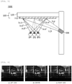
- FIG. 5 is a view illustrating an example of a head-mounted display device according to another aspect of the present disclosure, specifically, a view schematically illustrating only a portion applied to the right pupil of the wearer.
- a head-mounted display device 1000 may include a display lens 100 manufactured by the method according to an aspect of the present disclosure, and an optical engine 200 configured to cause image light, diverging along an irradiation direction, to be incident on a holographic optical element 110 included in the display lens 100.
- the holographic optical element 110 may be formed by recording a hologram on a photosensitive substrate in which a light-transmissive film is coated with a photosensitive material.
- the holographic optical element 110 may be bonded to a lens 120 to form the display lens 100.
- the holographic optical element 110 may be formed by recording a hologram on a photosensitive substrate in which the lens 120 is coated with a photosensitive material.
- the lens 120 and the holographic optical element 110 formed by the recording on the photosensitive material may be stacked to form the display lens 100.
- the lens 120 is a light-transmissive lens formed of transparent glass or polymer resin
- external light may be transmitted as it is. Therefore, a wearer of the head-mounted display device 1000 may recognize an object, a background, and the like of the natural world as they are, and light input through the optical engine 200 may be diffracted in a manner of being reflected by the reflection holographic optical element 110, such that the wearer may see the light displayed as a virtual image floating on the object, the background, and the like of the natural world.
- the optical engine 200 is a device configured to cause diverging image light to be incident on the holographic optical element 110 in the display lens 100 manufactured by the method according to an aspect of the present disclosure, and a display device such as a laser beam scan projector, a liquid crystal display (LCD), or an organic light emitting diode (OLED) may be used.
- a display device such as a laser beam scan projector, a liquid crystal display (LCD), or an organic light emitting diode (OLED) may be used.
- RGB wavelengths of first laser light and second laser light and incident angles of the first laser light and the second laser light with respect to the photosensitive substrate 10 may be adjusted by considering conditions such as RGB wavelengths used in the optical engine 200 according to another aspect of the present disclosure, a position of the optical engine 200, and a divergence angle of image light output through the optical engine 200.
- an R wavelength used in the optical engine 200 may be selected from a range of 620 to 660 nm
- a G wavelength may be selected from a range of 520 to 560 nm
- a B wavelength may be selected from a range of 440 to 470 nm
- the incident angle of the image light output through the optical engine 200 with respect to the holographic optical element may be selected from a range of 40° to 70°
- the divergence angle of the image light may be selected from a range of 20° to 60°.
- holograms with different coherence characteristics are recorded at an arbitrary position of the holographic optical element 110.
- a plurality of different light reflection paths Lo_a, Lo_a', Lo_a", Lo_b, Lo_b', and Lo_b" may be formed by diffraction and reflection, thereby making it possible to implement a plurality of exit pupils EP1, EP2, and EP3.
- the larger the number of exit pupils, the larger the size of an eye motion box may be.
- a plurality of exit pupils may be implemented.
- FIG. 6 is a view showing an effect obtained by the plurality of exit pupils implemented in the head-mounted display device 1000 according to an embodiment of the present disclosure.
- FIG. 6 shows pictures of an image that the user can visually recognize by using the head-mounted display device 1000 implemented according to an embodiment of the present disclosure, and it may be seen that a clear image is implemented without a problem in that the image looks like multiple images or a region in which the image is not seen is generated even when the position the pupil is changed to the left side (a), to the center (b), and to the right side (c) on assumption that a position of the pupil of the actual user is changed.
Landscapes
- Physics & Mathematics (AREA)
- General Physics & Mathematics (AREA)
- Optics & Photonics (AREA)
- Engineering & Computer Science (AREA)
- Manufacturing & Machinery (AREA)
- Diffracting Gratings Or Hologram Optical Elements (AREA)
- Holo Graphy (AREA)
- Optical Elements Other Than Lenses (AREA)
Abstract
Description
- The present disclosure claims priority to and the benefit of
Korean Patent Application No. 10-2019-0120075 filed in the Korean Intellectual Property Office on September 27, 2019 - In recent, with a growing interest in a display device that implements augmented reality (AR), mixed reality (MR), or virtual reality (VR), a study of such a display device has been actively conducted. A display unit that implements AR, MR, or VR includes a diffractive light guide plate that uses a diffraction phenomenon based on a wave-like nature of light.
- As such a diffractive light guide plate, a type that includes a plurality of diffractive optical elements with a plurality of relief grating patterns and a type that includes a transmission holographic optical element as a photosensitive material having an interference pattern recorded thereon are mainly used.
- Meanwhile, in a case of the type that includes the diffractive optical element, color separation efficiency is low, and thus image crosstalk may occur. In a case of the type that includes the diffractive optical element or transmission holographic optical element, a great overall optical loss may be caused.
- On the other hand, in a case of a type that includes a reflection holographic optical element, color separation efficiency is high and optical loss is less than that of the diffractive optical element/transmission holographic optical element. However, it is difficult to increase the number of exit pupils that affects the size of an eye box, which is disadvantageous.
- Since the above-described background art is technical information possessed by the inventor for deriving embodiments of the present disclosure or acquired in the process of deriving embodiments of the present disclosure, it may not be necessarily said that the background art is a publicly known technique disclosed to the general public before filing the application for the embodiments of the present disclosure.
- Embodiments of the present disclosure intend to provide a device for manufacturing a display lens including a reflection holographic optical element for implementing a plurality of exit pupils, a method for manufacturing the display lens, and a head-mounted display device including the display lens manufactured thereby.
- The technical problem of the present disclosure is not limited to the aforementioned problem, and the other unmentioned problems will be clearly understood by those skilled in the art from the following description.
- An embodiment according to an aspect of the present disclosure provides a device for manufacturing a display lens including a holographic optical element formed by recording a hologram on a photosensitive substrate, in which a substrate is coated with a photosensitive material, through irradiation of laser beams, the device including: a first laser light incidence unit configured to cause first laser light, converging along an irradiation direction, to be incident on one surface of the photosensitive substrate; and a second laser light incidence unit configured to cause second laser light, diverging at a plurality of points along an irradiation direction, to be incident on the other surface of the photosensitive substrate.
- In the present embodiment, the second laser light incidence unit may include a lens array having one surface on which a plurality of lens portions configured to convert parallel light into diverging light are arranged, and parallel light incident on the lens array may be radiated as the second laser light, which is diverging light, toward the other surface of the photosensitive substrate at the plurality of points through the respective lens portions.
- In the present embodiment, a non-light-transmissive mask may be disposed around a region corresponding to each lens portion on a side of the lens array that is opposite to a side where the lens portions are arranged.
- In the present embodiment, a distance between centers of the lens portions may be 4 to 6 mm.
- In the present embodiment, a focal length of the lens portion may be 2 to 10 mm.
- In the present embodiment, a radius of curvature of the lens portion may satisfy the following Equation 1:

- In the present embodiment, a diameter of the lens portion may be 1 to 3 mm.
- An embodiment according to another aspect of the present disclosure provides a method for manufacturing a display lens including a holographic optical element, the method including: a step (a) of causing first laser light, converging along an irradiation direction, to be incident on one surface of a photosensitive substrate in which a substrate is coated with a photosensitive material; and a step (b) of causing second laser light, diverging along an irradiation direction, to be incident on the other surface of the photosensitive substrate while the step (a) is performed, wherein in the step (b), parallel light is incident on a lens array having one surface on which a plurality of lens portions configured to convert parallel light into diverging light are arranged, such that the second laser light is radiated toward the other surface of the photosensitive substrate at a plurality of points through the respective lens portions.
- In the present embodiment, the substrate may be a light-transmissive lens.
- In the present embodiment, the method may further include a step (c) of stacking the photosensitive substrate subjected to the step (a) and the step (b) and a light-transmissive lens by interposing a light-transmissive adhesive between the photosensitive substrate and the light-transmissive lens, wherein the substrate is a light-transmissive film.
- An embodiment according to still another aspect of the present disclosure provides a head-mounted display device including: a display lens manufactured by the method according to an aspect of the present disclosure; and an optical engine configured to cause image light, diverging along an irradiation direction, to be incident on a holographic optical element included in the display lens.
- In the present embodiment, an interval between centers of a plurality of exit pupils formed in the display lens may be 4 to 6 mm.
- When image light is incident on the reflection holographic optical element, manufactured by the device and method for manufacturing a display lens according to an aspect of the present disclosure, by using the optical engine, a plurality of hologram patterns with different coherence characteristics are recorded at an arbitrary position, and thus a plurality of different light reflection paths may be formed by reflection, thereby making it possible to implement a plurality of exit pupils.
- The effects of the present disclosure are not limited to those described above, and effects that are not mentioned may be clearly understood by those skilled in the art from the present specification and the accompanying drawing.
-
-
FIG. 1 is a view schematically illustrating a device for implementing a method for manufacturing a display lens according to an aspect of the present disclosure. -
FIG. 2 is a schematic plan view of a lens array used in the method for manufacturing a display lens according to an aspect of the present disclosure. - (a) of
FIG. 3 is a view schematically illustrating a side cross-section of a portion of a lens array according to an embodiment in which a lens portion has a convex shape, and (b) ofFIG. 3 is a view schematically illustrating a side cross-section of a portion of a lens array according to another embodiment in which a lens portion has a concave shape. -
FIG. 4 is a view illustrating results of simulating a focal length and a field of view of a lens portion according to the radius of curvature of the lens portion. -
FIG. 5 is a view illustrating an example of a head-mounted display device according to another aspect of the present disclosure. -
FIG. 6 is a view showing a plurality of exit pupils formed in the display lens according to an aspect of the present disclosure. - The present disclosure will become apparent from embodiments to be described below in detail together with the accompanying drawings. However, the present disclosure is not limited to embodiments to be described below, but may be implemented in various different forms, these embodiments will be provided only in order to make the present disclosure complete and allow those skilled in the art to completely recognize the scope of the present disclosure, and the present disclosure will be defined by the scope of the claims. Meanwhile, terms used in the present specification are for explaining embodiments rather than limiting the present disclosure.
- In the present specification, a singular form includes a plural form, unless the context clearly indicates otherwise. Components, steps, operations, and/or elements mentioned by terms "comprise" and/or "comprising" used in the present specification do not exclude the existence or addition of one or more other components, steps, operations, and/or elements. Terms "first", "second", and the like, may be used to describe various components, but the components should not be construed as being limited by these terms. The terms are used only to distinguish one component from another component.
- Hereinafter, the present disclosure will be described in detail with reference to the drawings.
-
FIG. 1 is a view schematically illustrating a device for implementing a method for manufacturing a display lens according to an aspect of the present disclosure. - The method for manufacturing a display lens according to an aspect of the present disclosure is for manufacturing a display lens used in a display device that implements virtual reality or augmented reality, and a display lens including a holographic optical element formed by recording a hologram on a photosensitive substrate through irradiation of two mutually coherent laser beams is manufactured by the method.
- The holographic optical element to be formed by using the method according to an aspect of the present disclosure is a reflection holographic optical element which reflects image light, emitted by an optical engine to be incident thereon, by diffraction. The reflection holographic optical element is also called an off-axis reflector, because an incident angle of the image light incident on the holographic optical element and a reflection angle of the image light reflected by the holographic optical element are different from each other.
- It is known that such a holographic optical element may be manufactured in a manner in which one surface of the photosensitive substrate is exposed to an object wave and the other surface of the photosensitive substrate that is opposite to the one surface is exposed to a reference wave.
- A device A for manufacturing a display lens according to an embodiment of an aspect of the present disclosure may be used to manufacture the display lens including the holographic optical element formed by recording a hologram on a photosensitive substrate 10, in which a substrate 11 is coated with a photosensitive material 12, through irradiation of laser beams.
- The device A for manufacturing a display lens may include a first laser light incidence unit B configured to cause first laser light L1, converging along an irradiation direction, to be incident on one surface 10a of the photosensitive substrate 10, and a second laser light incidence unit C configured to cause second laser light L2a, L2b, L2c, and the like, diverging at a plurality of points along an irradiation direction, to be incident on the other surface 10b of the photosensitive substrate 10.
- The device A for manufacturing a display lens according to an embodiment of the present disclosure may include a laser device 1 that generates laser beams and propagates the laser beams to the first laser light incidence unit B and the second laser light incidence unit C, respectively. The laser device 1 may include three laser light sources (not illustrated) with light emission wavelengths corresponding to three wavelengths of RGB, and a combiner (not illustrated) that enables coaxial propagation of laser beams output from the three laser light sources, respectively.
- The laser beams that coaxially propagate by the laser device 1 may be split into two paths by a beam splitter 2 toward the first laser light incidence unit B and the second laser light incidence unit C, respectively.
- The first laser light incidence unit B may include a first lens 3 and a second lens 4. A laser beam LB1 in a first path P1 may be converted into diverging light γ whose diameter is increased by the first lens 3 and then be converted into converging light δ by the second lens 4, and the converging light δ may be defined as the first laser light L1 incident on the one surface 10a of the photosensitive substrate 10.
- The second laser light incidence unit C may include a
lens array 20 having one surface on which a plurality oflens portions 22 configured to convert parallel light α into diverging light β are arranged. As the parallel light α is incident on the lens array, the second laser light L2a, L2b, L2c, and the like may be radiated toward the other surface 10b of the photosensitive substrate 10 at a plurality of points through therespective lens portions 22. - In addition, the second laser light incidence unit C may further include a third lens 5 and a
fourth lens 6. A laser beam LB2 in a second path P2 may be converted into diverging light ε whose diameter is increased by the third lens 5 and then be converted into the parallel light α by thefourth lens 6, and the parallel light α may be converted into the diverging light β and the diverging light β may be radiated at a plurality of points by thelens array 20 as described above. Here, the diverging light β radiated at the plurality of points may be defined as a plurality of second laser light L2a, L2b, L2c, and the like incident on the other surface 10b of the photosensitive substrates 10. - In the device A for manufacturing a display lens according to an embodiment of the present disclosure, as the parallel light α is incident on a wide area of a side of the
lens array 20 that is opposite to a side on which thelens portions 22 are arranged, the parallel light α is converted into the diverging light β, and the diverging light β is radiated as the plurality of rays of second laser light L2a, L2b, L2c, and the like, at a plurality of points through therespective lens portions 22 on the side on which thelens portions 22 are arranged. Therefore, a region in which the plurality of rays of second laser light L2a, L2b, L2c, and the like overlap one another may be easily formed on the photosensitive substrate 10. As such, in the region in which the plurality of rays of second laser light L2a, L2b, L2c, and the like overlap one another, the first laser light L1 interferes with all the respective rays of second laser light L2a, L2b, L2c, and the like at one arbitrary point, such that a plurality of holograms with different coherence characteristics may be recorded at the point. When predetermined image light is incident on the holographic optical element formed as described above, a plurality of different light reflection paths may be formed by diffraction and reflection by the plurality of holograms with different coherence characteristics, thereby making it possible to easily implement a plurality of exit pupils. - Hereinafter, a process in which the first laser light L1 and the second laser light L2 are incident on the photosensitive substrate 10 will be described.
- The method for manufacturing a display lens according to an embodiment of an aspect of the present disclosure includes: a step (a) of causing the first laser light L1, converging along the irradiation direction, to be incident on the one surface 10a of the photosensitive substrate 10 in which the substrate 11 is coated with the photosensitive material 12; and a step (b) of causing the second laser light L2a, L2b, L2c, and the like, diverging along the irradiation direction, to be incident on the other surface 10b of the photosensitive substrate 10 while the step (a) is performed. In the step (b), parallel light α may be incident on the
lens array 20 having one surface on which the plurality oflens portions 22 configured to convert the parallel light α into diverging light β are arranged, such that the second laser light L2a, L2b, L2c, and the like may be radiated at the plurality of points toward the other surface 10b of the photosensitive substrate 10 through therespective lens portions 22. - The substrate 11 is coated with the photosensitive material 12 for hologram recording. In the field of hologram, various types of photosensitive materials that may be used to make a copy of the holographic optical element have been publicly known, and such materials may be used in the present disclosure as well without any limitation. Examples of the photosensitive material include a photopolymer, a photoresist, a silver halide emulsion, dichromated gelatin, a photographic emulsion, a photothermoplastic material, and a photorefractive material.
- According to an embodiment, the substrate 11 may be a light-transmissive lens. For example, the substrate 11 may be an optically transparent or translucent high reflective glass lens or high reflective plastic lens.
- According to another embodiment, the substrate 11 may be a light-transmissive film, that is, an optically transparent film having no anisotropy. For example, the substrate 11 may be a film containing triacetyl cellulose (TAC), polyethylene (PE), polycarbonate (PC), polypropylene (PP), polyamide (PA), polyethylene terephthalate (PET), or the like, but is not particularly limited thereto. In a case where the substrate 11 is a light-transmissive film, the method according to an embodiment of the present disclosure may include a step (c) of stacking the photosensitive substrate 10 and a light-transmissive lens (not illustrated) by interposing a light-transmissive adhesive between the photosensitive substrate 10 and the light-transmissive lens, the photosensitive substrate 10 having the hologram recorded thereon through the step (a) and the step (b). By doing so, a display lens including the holographic optical element may be manufactured.
- With the photosensitive substrate 10 in which the substrate 11 that is a light-transmissive lens or light-transmissive film is coated with the photosensitive material 12, the display lens manufactured by the method according to an embodiment of the present disclosure also has a structure through which external light may be transmitted. Therefore, the display lens may be used as a see-through lens that may implement augmented reality.
-
FIG. 2 is a schematic plan view of the lens array used in the method for manufacturing a display lens according to an aspect of the present disclosure. - The
lens array 20 used in the method for manufacturing a display lens according to an embodiment of the present disclosure may include a visible-light-transmissive plate-type base 21 having a predetermined thickness, and the plurality oflens portions 22 formed integrally with one surface of the plate-type base 21, having a concave shape or convex shape, and arranged while being spaced apart from one another. The plate-type base 21 and the plurality oflens portions 22 may be formed of the same material and provided integrally. For example, a material such as optical glass such as BK7 or quartz, normal transparent glass, or transparent plastic may be used. - (a) of
FIG. 3 is a view schematically illustrating a side cross-section of a portion of the lens array according to an embodiment in which the lens portion has a convex shape, and (b) ofFIG. 3 is a view schematically illustrating a side cross-section of a portion of a lens array according to another embodiment in which the lens portion has a concave shape. - A non-light-
transmissive mask 23 may be disposed around a region corresponding to eachlens portion 22 on aside 20b of thelens array 20 that is opposite to aside 20a on which thelens portions 22 are arranged. The non-light-transmissive mask 23 may be a metal thin film that may block visible light, and a metal such as Cr, Al, or Mo may be used. - Meanwhile, a distance G between centers of the
lens portions 22 needs to be the same as or larger than a normal pupil size of a human. The distance G between the centers of thelens portions 22 is preferably 4 to 6 mm. A plurality of rays of second laser light radiated through twoadjacent lens portions 22 form an overlapping region on the photosensitive substrate 10 to record a plurality of different holograms at an arbitrary point. However, image light incident on the holographic optical element formed by using thelens array 20 in which the distance G between the centers of thelens portions 22 is smaller than 4 mm may cause a problem in that even when the image light is reflected in a plurality of different light reflection paths, in a case of an image having a predetermined area, all the image light reaches a user's pupil, such that the image looks like multiple images. Meanwhile, image light incident on the holographic optical element formed by using thelens array 20 in which the distance G between the centers of thelens portions 22 is larger than 6 mm is reflected in a plurality of different light reflection paths to form a plurality of exit pupils, but results in a disadvantage in that a region in which the image is not seen according to a position of a wearer's pupil is increased, because the number of exit pupils per unit area is small. - In addition, as described above, the distance G between the centers of the
lens portions 22 may correspond to an interval between centers of a plurality of exit pupils formed in the holographic optical element or display lens. Therefore, the interval between the centers of the plurality of exit pupils may also be in a range of 4 to 6 mm. In a case where the interval between the centers of the exit pupils is smaller than 4 mm, a problem may occur in that the image looks like multiple images to the user. In a case where the interval between the centers of the exit pupils is larger than 6 mm, the region in which the image is not seen according to a position of the user's pupil is increased. - Meanwhile, the smaller the focal length F of the
lens portion 22, the wider the field of view of the holographic optical element formed by recording through thelens portion 22. That is, the use of thelens portion 22 with a small focal length F facilitates manufacturing of the holographic optical element that implements a wide field of view. The field of view of the holographic optical element may be substantially the same as a divergence angle of the second laser light radiated through thelens portion 22. However, in a case where the focal length of thelens portion 22 is excessively small, a possibility for distortion of the image of the image light reflected by the holographic optical element formed by recording through thelens portion 22 is increased due to aberration of thelens portion 22. - Therefore, in terms of the recording of the holographic optical element for preventing the distortion of the image of the image light reflected by the holographic optical element while securing a predetermined level of field of view, the focal length F of the
lens portion 22 is preferably 2 to 10 mm. - In the present embodiment, the radius R of curvature of the
lens portion 22 may satisfy the following Equation 1.
- Here, F represents the focal length of the
lens portion 22, n represents the refractive index of thelens array 20, and R represents the radius of curvature of thelens portion 22. - In a case where the refractive index n of the
lens array 20 is 1.5, and the focal length F of thelens portion 22 is 2 to 10 mm, an appropriate radius R of curvature of thelens portion 22 may be 1 to 5 mm according to Equation 1. -
FIG. 4 is a view illustrating results of simulating the focal length and the field of view of thelens portion 22 according to the radius of curvature of thelens portion 22. - It is assumed that a refractive index of each of the
lens portion 22 that is a simulation target and thelens array 20 is 1.52. - (a) of
FIG. 4 illustrates a case where the radius of curvature of thelens portion 22 is 1.5 mm, in which the focal length F of thelens portion 22 was calculated as about 2.9 mm, and the field of view (FOV) of thelens portion 22 was calculated as about 60° according to Equation 1. - (b) of
FIG. 4 illustrates a case where the radius of curvature of thelens portion 22 is 2.5 mm, in which the focal length F of thelens portion 22 was calculated as about 4.8 mm, and the field of view (FOV) of thelens portion 22 was calculated as about 40° according to Equation 1. - (c) of
FIG. 4 illustrates a case where the radius of curvature of thelens portion 22 is 5 mm, in which the focal length F of thelens portion 22 was calculated as about 9.6 mm, and the field of view (FOV) of thelens portion 22 was calculated as about 20° according to Equation 1. - Meanwhile, in the description of the present disclosure, the term "diameter of the lens portion" may refer to a diameter D of the
lens portion 22 measured when viewed from above the plate-type base 21 or a diameter D of an exposed region that is not blocked by the non-light-transmissive mask 23. - In the present embodiment, the diameter D of the
lens portion 22 may be 1 to 3 mm. The diameter D of thelens portion 22 may be determined in consideration of the distance G between the centers of thelens portions 22. For example, the distance G between the centers of thelens portions 22 may be 4 to 6 mm, and in a case where the diameter D of thelens portion 22 is 4 mm or more, therespective lens portions 22 may be in contact with each other or overlap each other and thus may not function asindependent lens portions 22, which is problematic. Further, in a case where the diameter D of thelens portion 22 is larger than 3 mm, fabrication may become difficult in consideration of the radius of curvature of thelens portion 22. In a case where the diameter D of thelens portion 22 is smaller than 1 mm, the exposed region that is not blocked by the non-light-transmissive mask 23 is significantly decreased, and thus the area of the second laser light radiated through thelens portion 22 is also decreased, which causes deterioration in hologram recording efficiency. -
FIG. 5 is a view illustrating an example of a head-mounted display device according to another aspect of the present disclosure, specifically, a view schematically illustrating only a portion applied to the right pupil of the wearer. - A head-mounted
display device 1000 according to another aspect of the present disclosure may include adisplay lens 100 manufactured by the method according to an aspect of the present disclosure, and anoptical engine 200 configured to cause image light, diverging along an irradiation direction, to be incident on a holographicoptical element 110 included in thedisplay lens 100. - According to an embodiment, the holographic
optical element 110 may be formed by recording a hologram on a photosensitive substrate in which a light-transmissive film is coated with a photosensitive material. In this case, the holographicoptical element 110 may be bonded to alens 120 to form thedisplay lens 100. - According to another embodiment, the holographic
optical element 110 may be formed by recording a hologram on a photosensitive substrate in which thelens 120 is coated with a photosensitive material. In this case, thelens 120 and the holographicoptical element 110 formed by the recording on the photosensitive material may be stacked to form thedisplay lens 100. - In a case where the
lens 120 is a light-transmissive lens formed of transparent glass or polymer resin, external light may be transmitted as it is. Therefore, a wearer of the head-mounteddisplay device 1000 may recognize an object, a background, and the like of the natural world as they are, and light input through theoptical engine 200 may be diffracted in a manner of being reflected by the reflection holographicoptical element 110, such that the wearer may see the light displayed as a virtual image floating on the object, the background, and the like of the natural world. - The
optical engine 200 is a device configured to cause diverging image light to be incident on the holographicoptical element 110 in thedisplay lens 100 manufactured by the method according to an aspect of the present disclosure, and a display device such as a laser beam scan projector, a liquid crystal display (LCD), or an organic light emitting diode (OLED) may be used. - Here, when manufacturing the
display lens 100 by the method according to an aspect of the present disclosure, RGB wavelengths of first laser light and second laser light and incident angles of the first laser light and the second laser light with respect to the photosensitive substrate 10 may be adjusted by considering conditions such as RGB wavelengths used in theoptical engine 200 according to another aspect of the present disclosure, a position of theoptical engine 200, and a divergence angle of image light output through theoptical engine 200. For example, an R wavelength used in theoptical engine 200 may be selected from a range of 620 to 660 nm, a G wavelength may be selected from a range of 520 to 560 nm, a B wavelength may be selected from a range of 440 to 470 nm, the incident angle of the image light output through theoptical engine 200 with respect to the holographic optical element may be selected from a range of 40° to 70°, and the divergence angle of the image light may be selected from a range of 20° to 60°. - In the head-mounted
display device 1000 according to an embodiment of the present disclosure, holograms with different coherence characteristics are recorded at an arbitrary position of the holographicoptical element 110. Thus, when image light Li_a and Li_b is incident on thedisplay lens 100, a plurality of different light reflection paths Lo_a, Lo_a', Lo_a", Lo_b, Lo_b', and Lo_b" may be formed by diffraction and reflection, thereby making it possible to implement a plurality of exit pupils EP1, EP2, and EP3. The larger the number of exit pupils, the larger the size of an eye motion box may be. In thedisplay device 1000, a plurality of exit pupils may be implemented. Thus, even when a position of an actual pupil of each wearer with respect to thedisplay lens 100 varies, a possibility for matching between an actual pupil and an exit pupil may be increased due to the existence of multiple exit pupils, thereby enabling the use for wearers with various body conditions, which is advantageous. -
FIG. 6 is a view showing an effect obtained by the plurality of exit pupils implemented in the head-mounteddisplay device 1000 according to an embodiment of the present disclosure.FIG. 6 shows pictures of an image that the user can visually recognize by using the head-mounteddisplay device 1000 implemented according to an embodiment of the present disclosure, and it may be seen that a clear image is implemented without a problem in that the image looks like multiple images or a region in which the image is not seen is generated even when the position the pupil is changed to the left side (a), to the center (b), and to the right side (c) on assumption that a position of the pupil of the actual user is changed. - Although the present disclosure has been described in relation to the preferred embodiments described above, various corrections or modifications can be made without departing from the subject matter and scope of the present disclosure. Therefore, the appended claims will include such corrections or modifications as long as they belong to the subject matter of the present disclosure.
Claims (12)
- A device for manufacturing a display lens including a holographic optical element formed by recording a hologram on a photosensitive substrate, in which a substrate is coated with a photosensitive material, through irradiation of laser beams, the device comprising:a first laser light incidence unit configured to cause first laser light, converging along an irradiation direction, to be incident on one surface of the photosensitive substrate; anda second laser light incidence unit configured to cause second laser light, diverging at a plurality of points along an irradiation direction, to be incident on the other surface of the photosensitive substrate.
- The device according to claim 1, wherein the second laser light incidence unit includes a lens array having one surface on which a plurality of lens portions configured to convert parallel light into diverging light are arranged, and parallel light incident on the lens array is radiated as the second laser light, which is diverging light, toward the other surface of the photosensitive substrate at the plurality of points through the respective lens portions.
- The device according to claim 2, wherein a non-light-transmissive mask is disposed around a region corresponding to each lens portion on a side of the lens array that is opposite to a side where the lens portions are arranged.
- The device according to claim 2, wherein a distance between centers of the lens portions is 4 to 6 mm.
- The device according to claim 2, wherein a focal length of the lens portion is 2 to 10 mm.
- The device according to claim 5, wherein a radius of curvature of the lens portion satisfies the following Equation 1:

- The device according to claim 2, wherein a diameter of the lens portion is 1 to 3 mm.
- A method for manufacturing a display lens including a holographic optical element, the method comprising:a step (a) of causing first laser light, converging along an irradiation direction, to be incident on one surface of a photosensitive substrate in which a substrate is coated with a photosensitive material; anda step (b) of causing second laser light, diverging along an irradiation direction, to be incident on the other surface of the photosensitive substrate while the step (a) is performed,wherein in the step (b), parallel light is incident on a lens array having one surface on which a plurality of lens portions configured to convert parallel light into diverging light are arranged, such that the second laser light is radiated toward the other surface of the photosensitive substrate at a plurality of points through the respective lens portions.
- The method according to claim 8, wherein the substrate is a light-transmissive lens.
- The method according to claim 8, further comprising a step (c) of stacking the photosensitive substrate subjected to the step (a) and the step (b) and a light-transmissive lens by interposing a light-transmissive adhesive between the photosensitive substrate and the light-transmissive lens,
wherein the substrate is a light-transmissive film. - A head-mounted display device comprising:a display lens manufactured by the method according to claim 8; andan optical engine configured to cause image light, diverging along an irradiation direction, to be incident on a holographic optical element included in the display lens.
- The head-mounted display device according to claim 11, wherein an interval between centers of a plurality of exit pupils formed in the display lens is 4 to 6 mm.
Applications Claiming Priority (2)
| Application Number | Priority Date | Filing Date | Title |
|---|---|---|---|
| KR20190120075 | 2019-09-27 | ||
| PCT/KR2020/012863 WO2021060828A1 (en) | 2019-09-27 | 2020-09-23 | Display lens manufacturing apparatus and method, and head-mounted display device comprising display lens manufactured thereby |
Publications (2)
| Publication Number | Publication Date |
|---|---|
| EP3958023A1 true EP3958023A1 (en) | 2022-02-23 |
| EP3958023A4 EP3958023A4 (en) | 2022-05-18 |
Family
ID=75165908
Family Applications (1)
| Application Number | Title | Priority Date | Filing Date |
|---|---|---|---|
| EP20870015.3A Pending EP3958023A4 (en) | 2019-09-27 | 2020-09-23 | APPARATUS AND METHOD OF MANUFACTURE OF A DISPLAY DEVICE AND HEAD MOUNTED DISPLAY DEVICE HAVING A DISPLAY LENS MADE THEREBY |
Country Status (7)
| Country | Link |
|---|---|
| US (1) | US11906744B2 (en) |
| EP (1) | EP3958023A4 (en) |
| JP (1) | JP7282439B2 (en) |
| KR (1) | KR102522116B1 (en) |
| CN (1) | CN113711105B (en) |
| TW (1) | TWI862689B (en) |
| WO (1) | WO2021060828A1 (en) |
Families Citing this family (1)
| Publication number | Priority date | Publication date | Assignee | Title |
|---|---|---|---|---|
| WO2025093895A1 (en) * | 2023-11-03 | 2025-05-08 | Ams-Osram Ag | Method of producing a holographic plate, apparatus and holographic plate |
Family Cites Families (25)
| Publication number | Priority date | Publication date | Assignee | Title |
|---|---|---|---|---|
| JPH05127022A (en) | 1991-03-29 | 1993-05-25 | Aisin Seiki Co Ltd | Manufacture of hologram for head-up display |
| JPH0713475A (en) | 1993-06-29 | 1995-01-17 | Nippondenso Co Ltd | Production of hologram |
| JPH08123302A (en) | 1994-10-19 | 1996-05-17 | Asahi Glass Co Ltd | Holographic display |
| JP3632271B2 (en) * | 1995-12-28 | 2005-03-23 | 富士ゼロックス株式会社 | Glasses display |
| JP3632392B2 (en) * | 1997-08-14 | 2005-03-23 | 富士ゼロックス株式会社 | Retina display device |
| KR100590519B1 (en) | 2000-12-08 | 2006-06-15 | 삼성전자주식회사 | Method for manufacturing diffuser for manufacturing hologram device of 3D display device and method for manufacturing hologram device using same |
| JP4180355B2 (en) | 2002-11-18 | 2008-11-12 | シャープ株式会社 | Hologram element manufacturing method using photomask and hologram element |
| KR20060133484A (en) * | 2005-06-20 | 2006-12-26 | 히다치 막셀 가부시키가이샤 | Lighting device, display device, optical sheet and manufacturing method thereof |
| KR20080037179A (en) | 2006-10-25 | 2008-04-30 | 삼성전자주식회사 | Holographic information recording / reproducing apparatus and holographic information recording / reproducing method |
| TWI421541B (en) * | 2006-10-26 | 2014-01-01 | Seereal Technologies Sa | Full image display device and method (2) |
| JP2008292916A (en) | 2007-05-28 | 2008-12-04 | Fujifilm Corp | Image exposure apparatus, microlens unit, and manufacturing method thereof |
| KR100971465B1 (en) | 2009-07-22 | 2010-07-26 | 정현인 | Integral photography sheet by special effect |
| JP5526681B2 (en) | 2009-09-29 | 2014-06-18 | 大日本印刷株式会社 | Holographic optical element and method of manufacturing holographic optical element |
| JP5561466B2 (en) | 2009-12-18 | 2014-07-30 | 大日本印刷株式会社 | Method for producing holographic optical element |
| US8727543B2 (en) * | 2010-09-07 | 2014-05-20 | Dai Nippon Printing Co., Ltd. | Projection type image display apparatus |
| US20150362734A1 (en) | 2013-01-28 | 2015-12-17 | Ecole Polytechnique Federale De Lausanne (Epfl) | Transflective holographic film for head worn display |
| KR20150136601A (en) * | 2013-03-25 | 2015-12-07 | 에꼴 뽈리떼끄닉 뻬데랄 드 로잔느 (으뻬에프엘) | Method for displaying an image projected from a head-worn display with multiple exit pupils |
| JP6179173B2 (en) * | 2013-04-24 | 2017-08-16 | 大日本印刷株式会社 | Method for manufacturing holographic optical element and holographic optical combiner including holographic optical element manufactured by the manufacturing method |
| KR20160066942A (en) | 2014-12-03 | 2016-06-13 | 서울대학교산학협력단 | Apparatus and method for manufacturing Holographic Optical Element |
| US10571696B2 (en) | 2014-12-26 | 2020-02-25 | Cy Vision Inc. | Near-to-eye display device |
| JP2017194547A (en) | 2016-04-20 | 2017-10-26 | コニカミノルタ株式会社 | Method of manufacturing holographic optical element, and exposure optical devices |
| JP6848310B2 (en) | 2016-09-30 | 2021-03-24 | セイコーエプソン株式会社 | Virtual image display device |
| US11054581B2 (en) | 2017-03-01 | 2021-07-06 | Akonia Holographics Llc | Ducted pupil expansion |
| JP7108450B2 (en) | 2018-04-13 | 2022-07-28 | 株式会社ディスコ | Polishing equipment |
| US11175505B2 (en) | 2018-09-24 | 2021-11-16 | Intel Corporation | Holographic optical elements for augmented reality devices and methods of manufacturing and using the same |
-
2020
- 2020-09-23 US US17/607,663 patent/US11906744B2/en active Active
- 2020-09-23 KR KR1020200123246A patent/KR102522116B1/en active Active
- 2020-09-23 WO PCT/KR2020/012863 patent/WO2021060828A1/en not_active Ceased
- 2020-09-23 JP JP2021563682A patent/JP7282439B2/en active Active
- 2020-09-23 EP EP20870015.3A patent/EP3958023A4/en active Pending
- 2020-09-23 CN CN202080029100.0A patent/CN113711105B/en active Active
- 2020-09-25 TW TW109133299A patent/TWI862689B/en active
Also Published As
| Publication number | Publication date |
|---|---|
| TW202118572A (en) | 2021-05-16 |
| KR20210037566A (en) | 2021-04-06 |
| CN113711105A (en) | 2021-11-26 |
| CN113711105B (en) | 2024-01-23 |
| EP3958023A4 (en) | 2022-05-18 |
| KR102522116B1 (en) | 2023-04-17 |
| WO2021060828A1 (en) | 2021-04-01 |
| US20220214549A1 (en) | 2022-07-07 |
| US11906744B2 (en) | 2024-02-20 |
| TWI862689B (en) | 2024-11-21 |
| JP2022530159A (en) | 2022-06-27 |
| JP7282439B2 (en) | 2023-05-29 |
Similar Documents
| Publication | Publication Date | Title |
|---|---|---|
| US9513480B2 (en) | Waveguide | |
| CN111480107B (en) | Optical system with dispersion compensation | |
| US12038721B2 (en) | Systems, devices, and methods for side lobe control in holograms | |
| CN115685696A (en) | Volume holographic grating and exposure angle determining method, manufacturing method and system thereof | |
| JP6507567B2 (en) | Optical element and image display device | |
| JP2007279313A (en) | Method for manufacturing optical element, optical element, image display device and head mount display | |
| US11409238B2 (en) | Systems, devices, and methods for aperture-free hologram recording | |
| US11747625B2 (en) | Light combiner and augmented reality device including the same | |
| CN113272718A (en) | Optical device and method of outputting light by using the same | |
| US11906744B2 (en) | Display lens manufacturing apparatus and method, and head-mounted display device comprising display lens manufactured thereby | |
| US20230273432A1 (en) | Slanted surface relief grating replication by optical proximity recording | |
| US11768461B2 (en) | Manufacturing method of holographic optical element and display device including holographic optical device manufactured thereby | |
| CN112859334A (en) | Near-to-eye display device and AR glasses | |
| US12498669B2 (en) | Method and system for simultaneous recording of superimposed holographic gratings for augmented reality devices (variants) | |
| JP2021103198A (en) | Optical member, display device, head-mounted display device, and manufacturing method of optical member | |
| JP2002258488A (en) | Exposure method and exposure device for manufacture of holographic optical element | |
| CN115685551A (en) | Optical element and virtual image display device | |
| JPH07290993A (en) | Head up display | |
| CN222580280U (en) | Grating preparation device | |
| CN114967152B (en) | Volume holographic optical element, manufacturing method thereof and head-up display | |
| US20240118552A1 (en) | Method of manufacturing optical element and projection device | |
| CN117148594A (en) | A display component and AR device | |
| HK40124968A (en) | Fixed focus image light guide system |
Legal Events
| Date | Code | Title | Description |
|---|---|---|---|
| STAA | Information on the status of an ep patent application or granted ep patent |
Free format text: STATUS: THE INTERNATIONAL PUBLICATION HAS BEEN MADE |
|
| PUAI | Public reference made under article 153(3) epc to a published international application that has entered the european phase |
Free format text: ORIGINAL CODE: 0009012 |
|
| STAA | Information on the status of an ep patent application or granted ep patent |
Free format text: STATUS: REQUEST FOR EXAMINATION WAS MADE |
|
| 17P | Request for examination filed |
Effective date: 20211116 |
|
| AK | Designated contracting states |
Kind code of ref document: A1 Designated state(s): AL AT BE BG CH CY CZ DE DK EE ES FI FR GB GR HR HU IE IS IT LI LT LU LV MC MK MT NL NO PL PT RO RS SE SI SK SM TR |
|
| REG | Reference to a national code |
Ref country code: DE Ref legal event code: R079 Free format text: PREVIOUS MAIN CLASS: G02B0003000000 Ipc: G03H0001040000 |
|
| A4 | Supplementary search report drawn up and despatched |
Effective date: 20220420 |
|
| RIC1 | Information provided on ipc code assigned before grant |
Ipc: G02B 27/01 20060101ALI20220412BHEP Ipc: G02B 5/32 20060101ALI20220412BHEP Ipc: G02B 3/00 20060101ALI20220412BHEP Ipc: G03H 1/04 20060101AFI20220412BHEP |
|
| DAV | Request for validation of the european patent (deleted) | ||
| DAX | Request for extension of the european patent (deleted) | ||
| STAA | Information on the status of an ep patent application or granted ep patent |
Free format text: STATUS: EXAMINATION IS IN PROGRESS |
|
| 17Q | First examination report despatched |
Effective date: 20250224 |