EP3957831A1 - Blade containment device - Google Patents
Blade containment device Download PDFInfo
- Publication number
- EP3957831A1 EP3957831A1 EP21191137.5A EP21191137A EP3957831A1 EP 3957831 A1 EP3957831 A1 EP 3957831A1 EP 21191137 A EP21191137 A EP 21191137A EP 3957831 A1 EP3957831 A1 EP 3957831A1
- Authority
- EP
- European Patent Office
- Prior art keywords
- shroud
- recess
- inside surface
- flange
- annular
- Prior art date
- Legal status (The legal status is an assumption and is not a legal conclusion. Google has not performed a legal analysis and makes no representation as to the accuracy of the status listed.)
- Granted
Links
Images



Classifications
-
- F—MECHANICAL ENGINEERING; LIGHTING; HEATING; WEAPONS; BLASTING
- F01—MACHINES OR ENGINES IN GENERAL; ENGINE PLANTS IN GENERAL; STEAM ENGINES
- F01D—NON-POSITIVE DISPLACEMENT MACHINES OR ENGINES, e.g. STEAM TURBINES
- F01D21/00—Shutting-down of machines or engines, e.g. in emergency; Regulating, controlling, or safety means not otherwise provided for
- F01D21/04—Shutting-down of machines or engines, e.g. in emergency; Regulating, controlling, or safety means not otherwise provided for responsive to undesired position of rotor relative to stator or to breaking-off of a part of the rotor, e.g. indicating such position
- F01D21/045—Shutting-down of machines or engines, e.g. in emergency; Regulating, controlling, or safety means not otherwise provided for responsive to undesired position of rotor relative to stator or to breaking-off of a part of the rotor, e.g. indicating such position special arrangements in stators or in rotors dealing with breaking-off of part of rotor
-
- F—MECHANICAL ENGINEERING; LIGHTING; HEATING; WEAPONS; BLASTING
- F01—MACHINES OR ENGINES IN GENERAL; ENGINE PLANTS IN GENERAL; STEAM ENGINES
- F01D—NON-POSITIVE DISPLACEMENT MACHINES OR ENGINES, e.g. STEAM TURBINES
- F01D11/00—Preventing or minimising internal leakage of working-fluid, e.g. between stages
- F01D11/08—Preventing or minimising internal leakage of working-fluid, e.g. between stages for sealing space between rotor blade tips and stator
-
- F—MECHANICAL ENGINEERING; LIGHTING; HEATING; WEAPONS; BLASTING
- F01—MACHINES OR ENGINES IN GENERAL; ENGINE PLANTS IN GENERAL; STEAM ENGINES
- F01D—NON-POSITIVE DISPLACEMENT MACHINES OR ENGINES, e.g. STEAM TURBINES
- F01D11/00—Preventing or minimising internal leakage of working-fluid, e.g. between stages
- F01D11/08—Preventing or minimising internal leakage of working-fluid, e.g. between stages for sealing space between rotor blade tips and stator
- F01D11/12—Preventing or minimising internal leakage of working-fluid, e.g. between stages for sealing space between rotor blade tips and stator using a rubstrip, e.g. erodible. deformable or resiliently-biased part
- F01D11/122—Preventing or minimising internal leakage of working-fluid, e.g. between stages for sealing space between rotor blade tips and stator using a rubstrip, e.g. erodible. deformable or resiliently-biased part with erodable or abradable material
-
- F—MECHANICAL ENGINEERING; LIGHTING; HEATING; WEAPONS; BLASTING
- F01—MACHINES OR ENGINES IN GENERAL; ENGINE PLANTS IN GENERAL; STEAM ENGINES
- F01D—NON-POSITIVE DISPLACEMENT MACHINES OR ENGINES, e.g. STEAM TURBINES
- F01D25/00—Component parts, details, or accessories, not provided for in, or of interest apart from, other groups
- F01D25/24—Casings; Casing parts, e.g. diaphragms, casing fastenings
- F01D25/243—Flange connections; Bolting arrangements
-
- F—MECHANICAL ENGINEERING; LIGHTING; HEATING; WEAPONS; BLASTING
- F02—COMBUSTION ENGINES; HOT-GAS OR COMBUSTION-PRODUCT ENGINE PLANTS
- F02C—GAS-TURBINE PLANTS; AIR INTAKES FOR JET-PROPULSION PLANTS; CONTROLLING FUEL SUPPLY IN AIR-BREATHING JET-PROPULSION PLANTS
- F02C7/00—Features, components parts, details or accessories, not provided for in, or of interest apart form groups F02C1/00 - F02C6/00; Air intakes for jet-propulsion plants
- F02C7/04—Air intakes for gas-turbine plants or jet-propulsion plants
- F02C7/05—Air intakes for gas-turbine plants or jet-propulsion plants having provisions for obviating the penetration of damaging objects or particles
- F02C7/052—Air intakes for gas-turbine plants or jet-propulsion plants having provisions for obviating the penetration of damaging objects or particles with dust-separation devices
-
- F—MECHANICAL ENGINEERING; LIGHTING; HEATING; WEAPONS; BLASTING
- F02—COMBUSTION ENGINES; HOT-GAS OR COMBUSTION-PRODUCT ENGINE PLANTS
- F02C—GAS-TURBINE PLANTS; AIR INTAKES FOR JET-PROPULSION PLANTS; CONTROLLING FUEL SUPPLY IN AIR-BREATHING JET-PROPULSION PLANTS
- F02C7/00—Features, components parts, details or accessories, not provided for in, or of interest apart form groups F02C1/00 - F02C6/00; Air intakes for jet-propulsion plants
- F02C7/04—Air intakes for gas-turbine plants or jet-propulsion plants
- F02C7/05—Air intakes for gas-turbine plants or jet-propulsion plants having provisions for obviating the penetration of damaging objects or particles
- F02C7/055—Air intakes for gas-turbine plants or jet-propulsion plants having provisions for obviating the penetration of damaging objects or particles with intake grids, screens or guards
-
- F—MECHANICAL ENGINEERING; LIGHTING; HEATING; WEAPONS; BLASTING
- F01—MACHINES OR ENGINES IN GENERAL; ENGINE PLANTS IN GENERAL; STEAM ENGINES
- F01D—NON-POSITIVE DISPLACEMENT MACHINES OR ENGINES, e.g. STEAM TURBINES
- F01D25/00—Component parts, details, or accessories, not provided for in, or of interest apart from, other groups
- F01D25/16—Arrangement of bearings; Supporting or mounting bearings in casings
-
- F—MECHANICAL ENGINEERING; LIGHTING; HEATING; WEAPONS; BLASTING
- F01—MACHINES OR ENGINES IN GENERAL; ENGINE PLANTS IN GENERAL; STEAM ENGINES
- F01D—NON-POSITIVE DISPLACEMENT MACHINES OR ENGINES, e.g. STEAM TURBINES
- F01D25/00—Component parts, details, or accessories, not provided for in, or of interest apart from, other groups
- F01D25/34—Turning or inching gear
-
- F—MECHANICAL ENGINEERING; LIGHTING; HEATING; WEAPONS; BLASTING
- F05—INDEXING SCHEMES RELATING TO ENGINES OR PUMPS IN VARIOUS SUBCLASSES OF CLASSES F01-F04
- F05D—INDEXING SCHEME FOR ASPECTS RELATING TO NON-POSITIVE-DISPLACEMENT MACHINES OR ENGINES, GAS-TURBINES OR JET-PROPULSION PLANTS
- F05D2220/00—Application
- F05D2220/30—Application in turbines
- F05D2220/32—Application in turbines in gas turbines
- F05D2220/323—Application in turbines in gas turbines for aircraft propulsion, e.g. jet engines
-
- F—MECHANICAL ENGINEERING; LIGHTING; HEATING; WEAPONS; BLASTING
- F05—INDEXING SCHEMES RELATING TO ENGINES OR PUMPS IN VARIOUS SUBCLASSES OF CLASSES F01-F04
- F05D—INDEXING SCHEME FOR ASPECTS RELATING TO NON-POSITIVE-DISPLACEMENT MACHINES OR ENGINES, GAS-TURBINES OR JET-PROPULSION PLANTS
- F05D2240/00—Components
- F05D2240/10—Stators
- F05D2240/14—Casings or housings protecting or supporting assemblies within
-
- F—MECHANICAL ENGINEERING; LIGHTING; HEATING; WEAPONS; BLASTING
- F05—INDEXING SCHEMES RELATING TO ENGINES OR PUMPS IN VARIOUS SUBCLASSES OF CLASSES F01-F04
- F05D—INDEXING SCHEME FOR ASPECTS RELATING TO NON-POSITIVE-DISPLACEMENT MACHINES OR ENGINES, GAS-TURBINES OR JET-PROPULSION PLANTS
- F05D2250/00—Geometry
- F05D2250/20—Three-dimensional
- F05D2250/23—Three-dimensional prismatic
- F05D2250/232—Three-dimensional prismatic conical
-
- F—MECHANICAL ENGINEERING; LIGHTING; HEATING; WEAPONS; BLASTING
- F05—INDEXING SCHEMES RELATING TO ENGINES OR PUMPS IN VARIOUS SUBCLASSES OF CLASSES F01-F04
- F05D—INDEXING SCHEME FOR ASPECTS RELATING TO NON-POSITIVE-DISPLACEMENT MACHINES OR ENGINES, GAS-TURBINES OR JET-PROPULSION PLANTS
- F05D2250/00—Geometry
- F05D2250/20—Three-dimensional
- F05D2250/29—Three-dimensional machined; miscellaneous
- F05D2250/294—Three-dimensional machined; miscellaneous grooved
-
- F—MECHANICAL ENGINEERING; LIGHTING; HEATING; WEAPONS; BLASTING
- F05—INDEXING SCHEMES RELATING TO ENGINES OR PUMPS IN VARIOUS SUBCLASSES OF CLASSES F01-F04
- F05D—INDEXING SCHEME FOR ASPECTS RELATING TO NON-POSITIVE-DISPLACEMENT MACHINES OR ENGINES, GAS-TURBINES OR JET-PROPULSION PLANTS
- F05D2250/00—Geometry
- F05D2250/70—Shape
- F05D2250/71—Shape curved
- F05D2250/712—Shape curved concave
-
- F—MECHANICAL ENGINEERING; LIGHTING; HEATING; WEAPONS; BLASTING
- F05—INDEXING SCHEMES RELATING TO ENGINES OR PUMPS IN VARIOUS SUBCLASSES OF CLASSES F01-F04
- F05D—INDEXING SCHEME FOR ASPECTS RELATING TO NON-POSITIVE-DISPLACEMENT MACHINES OR ENGINES, GAS-TURBINES OR JET-PROPULSION PLANTS
- F05D2260/00—Function
- F05D2260/60—Fluid transfer
- F05D2260/607—Preventing clogging or obstruction of flow paths by dirt, dust, or foreign particles
-
- Y—GENERAL TAGGING OF NEW TECHNOLOGICAL DEVELOPMENTS; GENERAL TAGGING OF CROSS-SECTIONAL TECHNOLOGIES SPANNING OVER SEVERAL SECTIONS OF THE IPC; TECHNICAL SUBJECTS COVERED BY FORMER USPC CROSS-REFERENCE ART COLLECTIONS [XRACs] AND DIGESTS
- Y02—TECHNOLOGIES OR APPLICATIONS FOR MITIGATION OR ADAPTATION AGAINST CLIMATE CHANGE
- Y02T—CLIMATE CHANGE MITIGATION TECHNOLOGIES RELATED TO TRANSPORTATION
- Y02T50/00—Aeronautics or air transport
- Y02T50/60—Efficient propulsion technologies, e.g. for aircraft
Definitions
- the present disclosure relates to containing rotational components of a turbomachine, and more specifically, containing impeller components, or fragments of components, released from an impeller assembly following structural failure.
- impeller components, component fragments, or other high-speed rotational components within the impeller enclosure is necessary.
- an enclosure surrounding fan blades of an aircraft engine are designed to absorb the impact of a fan blade released from the fan rotor.
- the enclosure may have divergent walls rather than cylindrical walls typical of some fan enclosures.
- the space provided for the impeller enclosure may be insufficient to incorporate the requisite energy-absorbing containment elements. In these instances, a detached impeller blade or other impeller fragment may contact the divergent enclosure walls and, thereafter, escape the enclosure.
- One such space-constrained impeller enclosure surrounds a scavenge blower of an inlet particle separator system. Positioned near the exhaust of the scavenged air stream, the scavenge blower facilitates discharging sand, dust, and other small debris contained within an air stream diverted from an aircraft engine inlet. Erosion protection for the enclosure is provided by a metal shroud radially outward from the scavenge blower, which may include divergent walls surrounding the impeller. Due to the high rotating speed of the scavenge impeller during operation, containment of impeller blades or other impeller fragments is necessary to prevent damage to the engine or any other surrounding areas.
- a shroud in accordance with one embodiment of the present invention includes an annular member extending along an axis from a first end to a second end and a flange extending radially outward at the second end.
- An inside surface of the annular member diverges from the first end towards the second end relative to the axis.
- a recess extends radially outward from the inside surface and circumferentially about the axis such that an axial extent of the recess at least partially coincides with an axial extent of the flange.
- the shroud is radially inward from an inlet housing and radially outward from an impeller to form a gap between the inside surface of the shroud and the tips of the impeller blades.
- the shroud recess has a position between trailing edges of the blades and the second end of the shroud.
- an impeller shroud with a divergent inner surface includes a recess devised to redirect a released impeller blade or other impeller fragment away from the impeller enclosure.
- the recess extends from the shroud inner surface and includes an axial extent that at least partially coincides with an axial extent of a flange located at a radially outermost end of the shroud. In the installed position, the flanged end supports the shroud while locating the shroud radially outward from tips of impeller blades to define a gap therebetween. Additionally, as installed, the recess is axially between trailing edges of the impeller blades and the flanged end of the shroud.
- Benefits of the present invention include solving the problems described above, such as containing an impeller blade, or other impeller fragment, following structural failure while respecting strict weight and space constraints. Following a structural failure of the impeller, a blade, or other fragment of the impeller, moves radially outwards to contact the shroud. Thereafter, the impeller fragment slides along the inside surface of the shroud to contact the recess of the shroud, transferring some kinetic energy from the impeller fragment to the enclosure and redirecting the fragment's trajectory away from the stationary enclosure. This reduces the energy of the fragment impact on the shroud and stationary enclosure, containing the impeller fragment within the enclosure while preventing any portion of the enclosure from separating.
- Other benefits of the present invention include, at least, reduced weight, reduced space, ease of manufacturability, and low cost.
- the present invention may be shown in a limited number of figures and described in a limited number of embodiments, such as an inlet particle separator in the context of a scavenge blower assembly for an aircraft engine particle separator system, the present invention is not limited to the figures and embodiments disclosed and may be used in any shroud and enclosure design in which the materials are insufficient to contain an impeller blade or impeller fragment following structural failure of the impeller.
- FIG. 1 is a cross-sectional view of scavenge blower assembly 10 of an aircraft engine particle separator system.
- Scavenge blower assembly 10 includes rotor assembly 12 housed within stationary enclosure 14. Rotor assembly 12 is driven and supported by drive support system 16.
- Stationary enclosure 14 supports at least some of drive support system 16 and defines flow path 18 adapted to direct an air stream, containing a mix of air and particles, towards exhaust 20 of scavenge blower assembly 10.
- Rotor assembly 12 includes impeller 22 mounted to shaft 24, which are rotatable about axis 26.
- Impeller 22 includes hub 28 and blades 30 which are circumferentially spaced about axis 26.
- Each of blades 30 is defined by one or more airfoil sections spaced along a radial direction relative to axis 26.
- Each airfoil section includes a convex suction-side curve, a concave pressure-side curve, and a linear chord line extending from leading edge 34 to trailing edge 36 that define suction-side and pressure-side surfaces of each blade 30.
- Blades 30 extend radially outwards relative to axis 26 from hub 28 to respective blade tips 32 and extend in a chordwise direction from leading edges 34 to respective trailing edges 36.
- Blade tips 32 diverge radially outward relative to axis 26 from leading edges 34 towards respective trailing edges 36. Tips 32 are shaped or positioned to create gap 38 between tips 32 and stationary enclosure 14.
- Stationary enclosure 14 includes inlet housing 40, outlet housing 42, fasteners 44, and shroud 46.
- Shroud 46 is radially inward from inlet housing 40 and radially outward from tips 32 of impeller blades 30 and defines a radially outer boundary of flow path 18.
- Inlet housing 40, shroud 46, and outlet housing 42 are axially clamped together by circumferentially spaced fasteners 44, with shroud 46 disposed between flanges of inlet housing 40 and outlet housing 42.
- Fasteners 44 may include external threads that engage internal threads 48 of outlet housing 42 as shown, or may be any other known fastener attachment.
- Inlet housing 40 defines opening 49 for flow path 18 so that air containing particles and debris can be diverted from an engine inlet to enter scavenge blower assembly 10, allowing the engine to be protected from harmful particles and debris.
- Shroud 46 provides erosion protection to housing by surrounding blade tips 32 such that abrasive particles and debris do not erode housing material during rotation of impeller 22.
- Shroud 46 provides primary containment in the event of a blade 30 failure during operation.
- Outlet housing 42 includes stationary vanes 60.
- Stationary vanes 60 extend radially inward from radially-inward-facing inner-outlet-housing surface 62 to radially-outward-facing inner-outlet-housing surface 64, being radially distributed around axis 26 and at least partially incident to a radially extending plane normal to axis 26. Stationary vanes 60 help to direct air flow as desired for ideal blower 10 operation but may also prevent an impeller blade or other impeller fragment from escaping stationary enclosure 14.
- impeller 22 and shroud 46 may be chosen to resist erosion from sand and other debris.
- shroud 46 and impeller 22 are steel, and inlet housing 40 and outlet housing 42 are aluminum.
- Drive support system 16 includes bearing 66, and accessory gearbox 72.
- Bearing 66 is supported by outlet housing 42 and is axially aligned with axis 26.
- Exterior end 74 of shaft 24 is structurally supported by and driven by gearbox 72 such that in operation impeller 22 is driven to high speeds, generating air flow and large radial forces of blades 30 in motion.
- the rotation of impeller 22 continuously pulls air flow into inlet housing 40 and pushes air out of outlet housing 42 through flow path 18.
- Shaft 24 includes rotor interface 76 at exterior end 74.
- Rotor interface 76 may be a shaft spline, such as a parallel key spline, a hub with internal spline, or other rotor interface feature used to transfer torque from a gearbox to a shaft.
- Shroud 46 can take a number of different forms. In the following description, four embodiments are described: a shroud of an assembly with a frustoconical recess ( FIG. 2A ), a shroud of an assembly with a frustoconical recess with a concave portion ( FIG. 2B ), a shroud of an assembly with a protrusion and a frustoconical recess with a concave portion ( FIG. 2C ), a shroud of an assembly with a recess with a concave surface ( FIG. 2D ).
- FIG. 2A a shroud of an assembly with a frustoconical recess
- FIG. 2B a shroud of an assembly with a protrusion and a frustoconical recess with a concave portion
- FIG. 2D a shroud of an assembly with a recess with a concave surface
- Fasteners 44 include bolts 78 and washers 80 used in tandem and fastened through one or more of inlet housing 40, shroud 46, and outlet housing 42 to axially clamp the components together.
- Outlet housing 42 is coupled to inlet housing 40, wherein flange 82 of shroud 46 is axially disposed between inlet and outlet housing 42, thereby axially restraining shroud 46 with respect to inlet housing 40 and outlet housing 42.
- shroud 46 includes annular member 84 extending from first end 86 to second end 88 relative to axis 26, and inside surface 90 radially inward from outside surface 92. Inside surface 90 diverges from first end 86 towards second end 88 relative to axis 26. The shape of inside surface 90 may be a conical frustrum.
- Shroud 46 further includes recess 94 and flange 82. Flange 82 is located at second end 88 and extends radially outward from outside surface 92.
- Recess 94 is located at second end 88 and extends radially outward from inside surface 90 and circumferentially about axis 26. An axial extent of recess 94 at least partially coincides with an axial extent of flange 82.
- Recess 94 is located between trailing edge 36 of blade 30 and second end 88 of annular member 84. Recess 94 may trap and, alternatively and/or in combination, deflect blades and blade fragments in a blade-off event.
- Radial depth of recess 94 is defined as the perpendicular distance from inside surface 90 to radially outermost point of recess 94 respective to axis 26.
- Axial width of recess is measured incident or tangent to inside surface 90 of shroud 46, in a direction incident to a plane that is incident to axis 26. Varying radial depth and axial width of recess 94 varies the likelihood of the blade to be trapped and/or deflected in a blade-off event.
- Factors that may be used to determine radial depth and axial width of recess 94 include: likelihood to trap blade or blade fragment; likelihood to deflect blade or blade fragment; axial width of flange 82 measured parallel to axis 26; thickness of annular member 84 of shroud 46 measured between inside surface 90 and outside surface 92; smallest distance between surfaces of recess 94 and any point on any hole surface of shroud 46 that receives or engages fastener 44; and cross-sectional shape of blade tip 32 dissected by a plane radially extending from and normal to axis 26.
- inlet housing 40 has first pilot surface 96 and outlet housing 42 has second pilot surface 98.
- Radially-outward-facing first annular surface 100 of shroud 46 opposes first pilot surface 96 of inlet housing 40.
- Radially-outward-facing second annular surface 102 of shroud 46 opposes second pilot surface 98 of outlet housing 42.
- Flange 82 is disposed between first annular surface 100 and second annular surface 102 of shroud 46.
- a summation of axial width of flange 82 with axial width of first annular surface 100 and axial width of second annular surface 102, each measured parallel to axis 26, is larger than an axial extent of recess 94.
- Such axial extent of recess 94 may be the greatest or that which is the greatest except for axial extents of convex fillets of recess 94 adjacent to inside surface 90.
- First annular surface 100 may be sized smaller than first pilot surface 96 and may be sized to engage or contact first pilot surface 96, such as in a first pilot fit.
- Second annular surface 102 may be sized smaller than second pilot surface 98 and may be sized to engage or contact second pilot surface 98, such as in a second pilot fit.
- First pilot fit and second pilot fit, or said engagements may act as force transfers and supports of shroud 46 such that, for example, when a blade portion contacts recess 94, outlet housing 42 absorbs a portion of the energy of the blade portion and alleviates the remaining portion of energy that is imparted to other components, such as inlet housing 40, shroud 46, and fastener 44.
- outlet housing 42 itself, through contact with shroud 46, absorbs a portion of the force of blade.
- Absorption of a portion of the force by outlet housing 42 may alleviate remaining force imparted on inlet housing 40 and such alleviation may prevent fracture of inlet housing 40.
- the absorption of force may also alleviate force on fasteners 44, such that fasteners 44 do not shear or break.
- Said absorption of force by outlet housing 42 may aid in trapping or deflecting blade, such as by maintaining the integrity of outlet housing 42 or stationary enclosure 14, preventing one or more fasteners 44 from breaking and allowing a gap to form between shroud 46 and outlet housing 42 and blade fragments to escape.
- Flange 82 of shroud 46 may be made wide and deep enough to absorb a large enough portion of the force of blade or blade fragment such that blade or blade fragment is contained within inlet housing 40 and outlet housing 42 and there is no fracture of any portion of the exterior of inlet housing 40 or outlet housing 42.
- Inlet housing 40 and/or outlet housing 42 may further comprise respective flanges adjacent to shroud 46 to aide in force absorption and/or assembly.
- FIG. 2A shows an enlarged view of an embodiment of second end of shroud assembled as part of scavenge blower assembly 10.
- Recess 94A extends radial depth into annular member 84 from inside surface 90.
- Outermost frustoconical surface 110A of recess 94A is frustoconical and is a bottom surface.
- Recess 94A includes first end surface 106A opposing second end surface 108A, both of which define ends of recess 94A and are adjacent to frustoconical surface 110A.
- Second end surface 108A is closest to second end 88 of shroud 46 and traps and/or deflects blades or blade fragments during a blade-off event.
- a benefit of this embodiment may include that recess 94A is simple and cost effective to manufacture.
- FIG. 2B shows an enlarged view of an exemplary embodiment of second end of shroud assembled as part of inlet particle separator.
- Recess 94B has first portion 104B joined to second portion 112B.
- First portion 104B extends first radial depth into annular member 84 from inside surface 90.
- Outermost frustoconical surface 110B of first portion 104B is frustoconical.
- Second portion 112B is located between first portion 104B and second end 88 of shroud 46. Second portion 112B extends second radial depth into annular member 84, measured from inside surface 90 and being greater than first radial depth.
- Recess 94B further comprises convex transition 114B from first portion 104B to second portion 112B and second portion 112B has radially outer surface 116B that is concave.
- first radial depth may be less than a thickness measured between inside surface 90 and outside surface 92.
- radial depth of recess measured perpendicular from the inside surface to the radially outermost point of the recess is less than said thickness.
- Benefits of second portion 112B may include further reducing weight of shroud 46 and increasing ability of shroud 46 to trap or deflect blade or blade fragments due to second portion 112B having a greater radial depth.
- a radially deeper recess 94B allows more of the blade or blade fragment to enter recess 94 and be more likely to be trapped or deflected by the recess.
- a benefit of having a concave radially outer surface 116B of second portion 112B is a lack of corners or edges and therefore smaller stress concentrations and being less likely to crack or fracture during an impact.
- convex transition 114B at least include that a blade or blade fragment is more likely to avoid contacting convex transition 114B in a way that deflects the blade or blade fragment away from radially deeper portions of recess 94B. Therefore, convex transition 114B increases the chance that blade or blade fragment will be trapped or deflected by recess 94B.
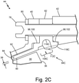
- FIG. 2C shows an enlarged view of an embodiment of second end of shroud assembled as part of inlet particle separator.
- Recess 94C has first portion 104C joined to second portion 112C.
- First portion 104C extends first radial depth into annular member 84 from inside surface 90 and is frustoconical.
- Second portion 112C is located between first portion 104C and second end 88 of shroud 46.
- Second portion 112C extends second radial depth into annular member 84, measured from inside surface 90 and being greater than first radial depth.
- Recess 94C further comprises convex transition 114C from first portion 104C to second portion 112C and second portion 112C has radially outer surface 116C that is concave.
- Recess 94C further comprises protrusion 118C extending radially inward from inside surface 90 of shroud 46 at end of second portion 112C that is closest to second end 88 of shroud 46.
- Benefits of protrusion 118C may include increasing the likelihood of trapping, and alternatively or in combination deflecting, a blade or blade fragment in a blade-off event. Detriments of using protrusion 118C may include that protrusion 118C reduces the efficiency of rotary assembly and therefore protrusion 118C should only be used if rotary assembly has capacity to handle a reduction in performance caused by protrusion 118C.
- FIG. 2D shows an enlarged view of an embodiment of second end of shroud assembled as part of inlet particle separator.
- Recess 94D includes concave surface 120D extending from first end 122D of recess on inside surface 90 to second end 124D of recess on inside surface 90.
- a benefit of this embodiment is that it may work to better deflect a blade or blade fragment, and therefore its force, in a blade-off event.
- This embodiment may, however, be less likely to trap a blade or blade fragment in a recess than embodiments described above. Deflecting, rather than trapping, may be desired in certain blade containment strategies such as deflecting a blade or blade fragment into stationary vanes.
- a shroud includes an annular member, a flange, and a recess.
- the annular member extends along an axis from a first end to a second end.
- An inside surface of the annular member is radially inward of an outside surface of the annular member and diverges from the first end towards the second end relative to the axis.
- the flange extends radially outward from the outside surface of the annular member at the second end of the annular member.
- the recess extends radially outward from the inside surface and circumferentially about the axis at the second end. The axial extent of the recess at least partially coincides with an axial extent of the flange.
- the shroud of the preceding paragraph can optionally include, additionally and/or alternatively, any one or more of the following features, configurations and/or additional components:
- the recess can include a first portion extending a first radial depth into the annular member from the inside surface and a second portion joined to the first portion and between the first portion and the second end of the shroud.
- the second portion extending a second radial depth into the annular member from the inside surface that is greater than the first radial depth.
- the recess can include a protrusion extending radially inward from the inside surface of the shroud at an end of the second portion closest to the second end of the shroud.
- a further embodiment of any of the foregoing shrouds, wherein the recess extends radially outward from the inside surface to a bottom surface and the bottom surface can be frustoconi cal.
- the recess can include a concave surface extending from a first end of the recess on the inside surface to a second end of the recess on the inside surface.
- the recess can extend from the inside surface by a radial depth defined as the perpendicular distance from the inside surface to the radially outermost point of the recess, and wherein the radial depth of the recess can be less than a thickness of the annular member defined between the inside surface and the outside surface.
- An assembly includes an impeller rotatable about an axis, an inlet housing surrounding the impeller, and a shroud.
- the impeller includes a plurality of blades, each blade extending radially outward with respect to the axis to a tip and extending in a chordwise direction from a leading edge to a trailing edge.
- the shroud includes an annular member, a flange, and a recess. The shroud is positioned radially inward from the inlet housing and radially outward form the impeller forming a gap between the inside surface of the shroud and the tips of the blades.
- a recess in the shroud is disposed between the trailing edges of the blades and the second end of the annular member.
- the assembly of the preceding paragraph can optionally include, additionally and/or alternatively, any one or more of the following features, configurations and/or additional components:
- annular member can extend along an axis from a first end to a second end and an inside surface of the annular member diverges from the first end towards the second end relative to the axis.
- the recess can include a first portion extending a first radial depth into the annular member from the inside surface and a second portion joined to the first portion and between the first portion and the second end of the shroud.
- the second portion extending a second radial depth into the annular member from the inside surface that is greater than the first radial depth.
- a further embodiment of any of the foregoing assemblies, wherein a radially outermost surface of the first portion can be annular.
- a further embodiment of any of the foregoing assemblies, wherein a radially outermost portion can be frustoconical.
- the recess can include a protrusion extending radially inward from the inside surface of the shroud at an end of the second portion closest to the second end of the shroud.
- the recess can include a concave surface extending from a first end of the recess on the inside surface to a second end of the recess on the inside surface.
- the recess can extend from the inside surface by a radial depth defined as the perpendicular distance from the inside surface to the radially outermost point of the recess, and wherein the radial depth of the recess can be less than a thickness of the annular member defined between the inside surface and the outside surface.
- a further embodiment of any of the foregoing assemblies can further include an outlet housing coupled to the inlet housing.
- a further embodiment of any of the foregoing assemblies, wherein a summation of an axial width of the flange, an axial width of the first annular surface, and an axial width of the second annular surface can be greater than an axial extent of the recess.
- first annular surface can extend from a first axial face of the flange and the second annular surface can extend from a second axial face of the flange opposite the first axial face.
Landscapes
- Engineering & Computer Science (AREA)
- Mechanical Engineering (AREA)
- General Engineering & Computer Science (AREA)
- Chemical & Material Sciences (AREA)
- Combustion & Propulsion (AREA)
- Structures Of Non-Positive Displacement Pumps (AREA)
Abstract
Description
- This invention was made with government support under W58RGZ16C0047 and W58RGZ19C0003 awarded by the United States Army. The government has certain rights in the invention.
- The present disclosure relates to containing rotational components of a turbomachine, and more specifically, containing impeller components, or fragments of components, released from an impeller assembly following structural failure.
- To improve safe operation of turbomachinery in the event of an impeller failure, containment of impeller components, component fragments, or other high-speed rotational components within the impeller enclosure is necessary. For example, an enclosure surrounding fan blades of an aircraft engine are designed to absorb the impact of a fan blade released from the fan rotor. However, in other applications, the enclosure may have divergent walls rather than cylindrical walls typical of some fan enclosures. Additionally, the space provided for the impeller enclosure may be insufficient to incorporate the requisite energy-absorbing containment elements. In these instances, a detached impeller blade or other impeller fragment may contact the divergent enclosure walls and, thereafter, escape the enclosure.
- One such space-constrained impeller enclosure surrounds a scavenge blower of an inlet particle separator system. Positioned near the exhaust of the scavenged air stream, the scavenge blower facilitates discharging sand, dust, and other small debris contained within an air stream diverted from an aircraft engine inlet. Erosion protection for the enclosure is provided by a metal shroud radially outward from the scavenge blower, which may include divergent walls surrounding the impeller. Due to the high rotating speed of the scavenge impeller during operation, containment of impeller blades or other impeller fragments is necessary to prevent damage to the engine or any other surrounding areas. However, because scavenge blowers are conventionally smaller than the engines they protect and may have strict weight and space constraints, typical blade-containment designs, such as those used for fan blade enclosures, are not ideal or practical. Accordingly, new containment elements and methods of containment are necessary for scavenge blower enclosures and other enclosures sharing like limitations.
- A shroud in accordance with one embodiment of the present invention includes an annular member extending along an axis from a first end to a second end and a flange extending radially outward at the second end. An inside surface of the annular member diverges from the first end towards the second end relative to the axis. At the second end of the shroud, a recess extends radially outward from the inside surface and circumferentially about the axis such that an axial extent of the recess at least partially coincides with an axial extent of the flange.
- In another embodiment, the shroud is radially inward from an inlet housing and radially outward from an impeller to form a gap between the inside surface of the shroud and the tips of the impeller blades. The shroud recess has a position between trailing edges of the blades and the second end of the shroud.
-
-
FIG. 1 is a cross-sectional view of an inlet particle separator blower taken through the rotational axis of the impeller. -
FIG. 2A is an enlarged partial cross-sectional view of an impeller shroud with a recess. -
FIG. 2B is an enlarged partial cross-sectional view of an impeller shroud with a recess in which a portion of the recess has a greater radial depth than another portion of the recess. -
FIG. 2C is an enlarged partial cross-sectional view of an impeller shroud with a recess with a protrusion extending into the flow path. -
FIG. 2D is an enlarged partial cross-sectional view of an impeller shroud with a recess that has a concave surface. - As described herein, an impeller shroud with a divergent inner surface includes a recess devised to redirect a released impeller blade or other impeller fragment away from the impeller enclosure. The recess extends from the shroud inner surface and includes an axial extent that at least partially coincides with an axial extent of a flange located at a radially outermost end of the shroud. In the installed position, the flanged end supports the shroud while locating the shroud radially outward from tips of impeller blades to define a gap therebetween. Additionally, as installed, the recess is axially between trailing edges of the impeller blades and the flanged end of the shroud.
- Benefits of the present invention include solving the problems described above, such as containing an impeller blade, or other impeller fragment, following structural failure while respecting strict weight and space constraints. Following a structural failure of the impeller, a blade, or other fragment of the impeller, moves radially outwards to contact the shroud. Thereafter, the impeller fragment slides along the inside surface of the shroud to contact the recess of the shroud, transferring some kinetic energy from the impeller fragment to the enclosure and redirecting the fragment's trajectory away from the stationary enclosure. This reduces the energy of the fragment impact on the shroud and stationary enclosure, containing the impeller fragment within the enclosure while preventing any portion of the enclosure from separating. Other benefits of the present invention include, at least, reduced weight, reduced space, ease of manufacturability, and low cost.
- While the present invention may be shown in a limited number of figures and described in a limited number of embodiments, such as an inlet particle separator in the context of a scavenge blower assembly for an aircraft engine particle separator system, the present invention is not limited to the figures and embodiments disclosed and may be used in any shroud and enclosure design in which the materials are insufficient to contain an impeller blade or impeller fragment following structural failure of the impeller.
-
FIG. 1 is a cross-sectional view ofscavenge blower assembly 10 of an aircraft engine particle separator system.Scavenge blower assembly 10 includesrotor assembly 12 housed withinstationary enclosure 14.Rotor assembly 12 is driven and supported bydrive support system 16.Stationary enclosure 14 supports at least some ofdrive support system 16 and definesflow path 18 adapted to direct an air stream, containing a mix of air and particles, towardsexhaust 20 ofscavenge blower assembly 10. -
Rotor assembly 12 includesimpeller 22 mounted toshaft 24, which are rotatable aboutaxis 26.Impeller 22 includeshub 28 andblades 30 which are circumferentially spaced aboutaxis 26. Each ofblades 30 is defined by one or more airfoil sections spaced along a radial direction relative toaxis 26. Each airfoil section includes a convex suction-side curve, a concave pressure-side curve, and a linear chord line extending from leadingedge 34 to trailingedge 36 that define suction-side and pressure-side surfaces of eachblade 30.Blades 30 extend radially outwards relative toaxis 26 fromhub 28 torespective blade tips 32 and extend in a chordwise direction from leadingedges 34 to respectivetrailing edges 36.Blade tips 32 diverge radially outward relative toaxis 26 fromleading edges 34 towards respectivetrailing edges 36.Tips 32 are shaped or positioned to creategap 38 betweentips 32 andstationary enclosure 14. -
Stationary enclosure 14 includesinlet housing 40,outlet housing 42,fasteners 44, andshroud 46. Shroud 46 is radially inward frominlet housing 40 and radially outward fromtips 32 ofimpeller blades 30 and defines a radially outer boundary offlow path 18. Inlethousing 40,shroud 46, andoutlet housing 42 are axially clamped together by circumferentially spacedfasteners 44, withshroud 46 disposed between flanges ofinlet housing 40 andoutlet housing 42.Fasteners 44 may include external threads that engageinternal threads 48 ofoutlet housing 42 as shown, or may be any other known fastener attachment. -
Inlet housing 40 definesopening 49 forflow path 18 so that air containing particles and debris can be diverted from an engine inlet to enterscavenge blower assembly 10, allowing the engine to be protected from harmful particles and debris. Shroud 46 provides erosion protection to housing by surroundingblade tips 32 such that abrasive particles and debris do not erode housing material during rotation ofimpeller 22. Shroud 46 provides primary containment in the event of ablade 30 failure during operation.Outlet housing 42 includesstationary vanes 60.Stationary vanes 60 extend radially inward from radially-inward-facing inner-outlet-housing surface 62 to radially-outward-facing inner-outlet-housing surface 64, being radially distributed aroundaxis 26 and at least partially incident to a radially extending plane normal toaxis 26.Stationary vanes 60 help to direct air flow as desired forideal blower 10 operation but may also prevent an impeller blade or other impeller fragment from escapingstationary enclosure 14. - The materials of
impeller 22 andshroud 46 may be chosen to resist erosion from sand and other debris. In anexemplary embodiment shroud 46 andimpeller 22 are steel, andinlet housing 40 andoutlet housing 42 are aluminum. - Drive
support system 16 includesbearing 66, andaccessory gearbox 72.Bearing 66 is supported byoutlet housing 42 and is axially aligned withaxis 26.Exterior end 74 ofshaft 24 is structurally supported by and driven bygearbox 72 such that inoperation impeller 22 is driven to high speeds, generating air flow and large radial forces ofblades 30 in motion. The rotation ofimpeller 22 continuously pulls air flow intoinlet housing 40 and pushes air out ofoutlet housing 42 throughflow path 18.Shaft 24 includesrotor interface 76 atexterior end 74.Rotor interface 76 may be a shaft spline, such as a parallel key spline, a hub with internal spline, or other rotor interface feature used to transfer torque from a gearbox to a shaft. -
Shroud 46 can take a number of different forms. In the following description, four embodiments are described: a shroud of an assembly with a frustoconical recess (FIG. 2A ), a shroud of an assembly with a frustoconical recess with a concave portion (FIG. 2B ), a shroud of an assembly with a protrusion and a frustoconical recess with a concave portion (FIG. 2C ), a shroud of an assembly with a recess with a concave surface (FIG. 2D ). Each of these figures includesshroud 46,impeller 22,inlet housing 40,outlet housing 42, andfasteners 44.Fasteners 44 includebolts 78 andwashers 80 used in tandem and fastened through one or more ofinlet housing 40,shroud 46, andoutlet housing 42 to axially clamp the components together.Outlet housing 42 is coupled toinlet housing 40, whereinflange 82 ofshroud 46 is axially disposed between inlet andoutlet housing 42, thereby axially restrainingshroud 46 with respect toinlet housing 40 andoutlet housing 42. - In each embodiment shown,
shroud 46 includesannular member 84 extending fromfirst end 86 tosecond end 88 relative toaxis 26, and insidesurface 90 radially inward fromoutside surface 92. Insidesurface 90 diverges fromfirst end 86 towardssecond end 88 relative toaxis 26. The shape ofinside surface 90 may be a conical frustrum.Shroud 46 further includes recess 94 andflange 82.Flange 82 is located atsecond end 88 and extends radially outward fromoutside surface 92. Recess 94 is located atsecond end 88 and extends radially outward frominside surface 90 and circumferentially aboutaxis 26. An axial extent of recess 94 at least partially coincides with an axial extent offlange 82. - Recess 94 is located between trailing
edge 36 ofblade 30 andsecond end 88 ofannular member 84. Recess 94 may trap and, alternatively and/or in combination, deflect blades and blade fragments in a blade-off event. Radial depth of recess 94 is defined as the perpendicular distance frominside surface 90 to radially outermost point of recess 94 respective toaxis 26. Axial width of recess is measured incident or tangent toinside surface 90 ofshroud 46, in a direction incident to a plane that is incident toaxis 26. Varying radial depth and axial width of recess 94 varies the likelihood of the blade to be trapped and/or deflected in a blade-off event. Factors that may be used to determine radial depth and axial width of recess 94 include: likelihood to trap blade or blade fragment; likelihood to deflect blade or blade fragment; axial width offlange 82 measured parallel toaxis 26; thickness ofannular member 84 ofshroud 46 measured betweeninside surface 90 and outsidesurface 92; smallest distance between surfaces of recess 94 and any point on any hole surface ofshroud 46 that receives or engagesfastener 44; and cross-sectional shape ofblade tip 32 dissected by a plane radially extending from and normal toaxis 26. - Furthermore, in each embodiment of
FIGS. 2A- 2D inlet housing 40 has first pilot surface 96 andoutlet housing 42 has second pilot surface 98. Radially-outward-facing first annular surface 100 ofshroud 46 opposes first pilot surface 96 ofinlet housing 40. Radially-outward-facing second annular surface 102 ofshroud 46 opposes second pilot surface 98 ofoutlet housing 42.Flange 82 is disposed between first annular surface 100 and second annular surface 102 ofshroud 46. - A summation of axial width of
flange 82 with axial width of first annular surface 100 and axial width of second annular surface 102, each measured parallel toaxis 26, is larger than an axial extent of recess 94. Such axial extent of recess 94 may be the greatest or that which is the greatest except for axial extents of convex fillets of recess 94 adjacent toinside surface 90. First annular surface 100 may be sized smaller than first pilot surface 96 and may be sized to engage or contact first pilot surface 96, such as in a first pilot fit. Second annular surface 102 may be sized smaller than second pilot surface 98 and may be sized to engage or contact second pilot surface 98, such as in a second pilot fit. First pilot fit and second pilot fit, or said engagements, may act as force transfers and supports ofshroud 46 such that, for example, when a blade portion contacts recess 94,outlet housing 42 absorbs a portion of the energy of the blade portion and alleviates the remaining portion of energy that is imparted to other components, such asinlet housing 40,shroud 46, andfastener 44. In other words,outlet housing 42 itself, through contact withshroud 46, absorbs a portion of the force of blade. Absorption of a portion of the force byoutlet housing 42 may alleviate remaining force imparted oninlet housing 40 and such alleviation may prevent fracture ofinlet housing 40. The absorption of force may also alleviate force onfasteners 44, such thatfasteners 44 do not shear or break. Said absorption of force byoutlet housing 42 may aid in trapping or deflecting blade, such as by maintaining the integrity ofoutlet housing 42 orstationary enclosure 14, preventing one ormore fasteners 44 from breaking and allowing a gap to form betweenshroud 46 andoutlet housing 42 and blade fragments to escape.Flange 82 ofshroud 46 may be made wide and deep enough to absorb a large enough portion of the force of blade or blade fragment such that blade or blade fragment is contained withininlet housing 40 andoutlet housing 42 and there is no fracture of any portion of the exterior ofinlet housing 40 oroutlet housing 42.Inlet housing 40 and/oroutlet housing 42 may further comprise respective flanges adjacent toshroud 46 to aide in force absorption and/or assembly. -
FIG. 2A shows an enlarged view of an embodiment of second end of shroud assembled as part ofscavenge blower assembly 10.Recess 94A extends radial depth intoannular member 84 frominside surface 90. Outermostfrustoconical surface 110A ofrecess 94A is frustoconical and is a bottom surface.Recess 94A includesfirst end surface 106A opposingsecond end surface 108A, both of which define ends ofrecess 94A and are adjacent tofrustoconical surface 110A.Second end surface 108A is closest tosecond end 88 ofshroud 46 and traps and/or deflects blades or blade fragments during a blade-off event. A benefit of this embodiment may include thatrecess 94A is simple and cost effective to manufacture. -
FIG. 2B shows an enlarged view of an exemplary embodiment of second end of shroud assembled as part of inlet particle separator.Recess 94B hasfirst portion 104B joined tosecond portion 112B.First portion 104B extends first radial depth intoannular member 84 frominside surface 90. Outermost frustoconical surface 110B offirst portion 104B is frustoconical.Second portion 112B is located betweenfirst portion 104B andsecond end 88 ofshroud 46.Second portion 112B extends second radial depth intoannular member 84, measured frominside surface 90 and being greater than first radial depth. Recess 94B further comprisesconvex transition 114B fromfirst portion 104B tosecond portion 112B andsecond portion 112B has radiallyouter surface 116B that is concave. In some embodiments, first radial depth may be less than a thickness measured betweeninside surface 90 and outsidesurface 92. In some embodiments, radial depth of recess measured perpendicular from the inside surface to the radially outermost point of the recess is less than said thickness. - Benefits of
second portion 112B may include further reducing weight ofshroud 46 and increasing ability ofshroud 46 to trap or deflect blade or blade fragments due tosecond portion 112B having a greater radial depth. A radiallydeeper recess 94B allows more of the blade or blade fragment to enter recess 94 and be more likely to be trapped or deflected by the recess. A benefit of having a concave radiallyouter surface 116B ofsecond portion 112B is a lack of corners or edges and therefore smaller stress concentrations and being less likely to crack or fracture during an impact. Benefits ofconvex transition 114B at least include that a blade or blade fragment is more likely to avoid contactingconvex transition 114B in a way that deflects the blade or blade fragment away from radially deeper portions ofrecess 94B. Therefore,convex transition 114B increases the chance that blade or blade fragment will be trapped or deflected byrecess 94B. -
FIG. 2C shows an enlarged view of an embodiment of second end of shroud assembled as part of inlet particle separator.Recess 94C hasfirst portion 104C joined tosecond portion 112C.First portion 104C extends first radial depth intoannular member 84 frominside surface 90 and is frustoconical.Second portion 112C is located betweenfirst portion 104C andsecond end 88 ofshroud 46.Second portion 112C extends second radial depth intoannular member 84, measured frominside surface 90 and being greater than first radial depth.Recess 94C further comprisesconvex transition 114C fromfirst portion 104C tosecond portion 112C andsecond portion 112C has radiallyouter surface 116C that is concave. -
Recess 94C further comprisesprotrusion 118C extending radially inward frominside surface 90 ofshroud 46 at end ofsecond portion 112C that is closest tosecond end 88 ofshroud 46. Benefits ofprotrusion 118C may include increasing the likelihood of trapping, and alternatively or in combination deflecting, a blade or blade fragment in a blade-off event. Detriments of usingprotrusion 118C may include thatprotrusion 118C reduces the efficiency of rotary assembly and therefore protrusion 118C should only be used if rotary assembly has capacity to handle a reduction in performance caused byprotrusion 118C. -
FIG. 2D shows an enlarged view of an embodiment of second end of shroud assembled as part of inlet particle separator.Recess 94D includesconcave surface 120D extending fromfirst end 122D of recess oninside surface 90 tosecond end 124D of recess oninside surface 90. A benefit of this embodiment is that it may work to better deflect a blade or blade fragment, and therefore its force, in a blade-off event. This embodiment may, however, be less likely to trap a blade or blade fragment in a recess than embodiments described above. Deflecting, rather than trapping, may be desired in certain blade containment strategies such as deflecting a blade or blade fragment into stationary vanes. - The following are non-exclusive descriptions of possible embodiments of the present invention.
- A shroud according to an exemplary embodiment of this disclosure, among other possible things, includes an annular member, a flange, and a recess. The annular member extends along an axis from a first end to a second end. An inside surface of the annular member is radially inward of an outside surface of the annular member and diverges from the first end towards the second end relative to the axis. The flange extends radially outward from the outside surface of the annular member at the second end of the annular member. The recess extends radially outward from the inside surface and circumferentially about the axis at the second end. The axial extent of the recess at least partially coincides with an axial extent of the flange.
- The shroud of the preceding paragraph can optionally include, additionally and/or alternatively, any one or more of the following features, configurations and/or additional components:
- A further embodiment of the foregoing shroud, wherein the inside surface of the annular member can be frustoconical.
- A further embodiment of any of the foregoing shrouds, wherein the recess can include a first portion extending a first radial depth into the annular member from the inside surface and a second portion joined to the first portion and between the first portion and the second end of the shroud. The second portion extending a second radial depth into the annular member from the inside surface that is greater than the first radial depth.
- A further embodiment of any of the foregoing shrouds, wherein the recess can include a convex transition from the first portion to the second portion.
- A further embodiment of any of the foregoing shrouds, wherein a radially outer surface of the second portion can be concave.
- A further embodiment of any of the foregoing shrouds, wherein a radially outermost surface of the first portion can be annular.
- A further embodiment of any of the foregoing shrouds, wherein a radially outermost portion can be frustoconical.
- A further embodiment of any of the foregoing shrouds, wherein the recess can include a protrusion extending radially inward from the inside surface of the shroud at an end of the second portion closest to the second end of the shroud.
- A further embodiment of any of the foregoing shrouds, wherein the second portion of the recess can include an axial extent less than and entirely within the axial extent of the flange.
- A further embodiment of any of the foregoing shrouds, wherein the first radial depth can be less than a thickness of the annular member defined between the inside surface and the outside surface.
- A further embodiment of any of the foregoing shrouds, wherein the recess extends radially outward from the inside surface to a bottom surface and the bottom surface can be frustoconi cal.
- A further embodiment of any of the foregoing shrouds, wherein the recess can include a concave surface extending from a first end of the recess on the inside surface to a second end of the recess on the inside surface.
- A further embodiment of any of the foregoing shrouds, wherein the recess can extend from the inside surface by a radial depth defined as the perpendicular distance from the inside surface to the radially outermost point of the recess, and wherein the radial depth of the recess can be less than a thickness of the annular member defined between the inside surface and the outside surface.
- An assembly according to an exemplary embodiment of this disclosure, among other possible things, includes an impeller rotatable about an axis, an inlet housing surrounding the impeller, and a shroud. The impeller includes a plurality of blades, each blade extending radially outward with respect to the axis to a tip and extending in a chordwise direction from a leading edge to a trailing edge. The shroud includes an annular member, a flange, and a recess. The shroud is positioned radially inward from the inlet housing and radially outward form the impeller forming a gap between the inside surface of the shroud and the tips of the blades. A recess in the shroud is disposed between the trailing edges of the blades and the second end of the annular member.
- The assembly of the preceding paragraph can optionally include, additionally and/or alternatively, any one or more of the following features, configurations and/or additional components:
- A further embodiment of the foregoing assembly, wherein the annular member can extend along an axis from a first end to a second end and an inside surface of the annular member diverges from the first end towards the second end relative to the axis.
- A further embodiment of any of the foregoing assemblies, wherein the flange can extend radially outward from an outside surface of the annular member.
- A further embodiment of any of the foregoing assemblies, wherein an axial extent of the recess can at least partially coincide with an axial extent of the flange.
- A further embodiment of any of the foregoing assemblies, wherein the inside surface of the annular member can be frustoconical.
- A further embodiment of any of the foregoing assemblies, wherein the recess can include a first portion extending a first radial depth into the annular member from the inside surface and a second portion joined to the first portion and between the first portion and the second end of the shroud. The second portion extending a second radial depth into the annular member from the inside surface that is greater than the first radial depth.
- A further embodiment of any of the foregoing assemblies, wherein the recess can include a convex transition from the first portion to the second portion.
- A further embodiment of any of the foregoing assemblies, wherein a radially outer surface of the second portion can be concave.
- A further embodiment of any of the foregoing assemblies, wherein a radially outermost surface of the first portion can be annular.
- A further embodiment of any of the foregoing assemblies, wherein a radially outermost portion can be frustoconical.
- A further embodiment of any of the foregoing assemblies, wherein the recess can include a protrusion extending radially inward from the inside surface of the shroud at an end of the second portion closest to the second end of the shroud.
- A further embodiment of any of the foregoing assemblies, wherein the second portion of the recess can include an axial extent less than and entirely within the axial extent of the flange.
- A further embodiment of any of the foregoing assemblies, wherein the first radial depth can be less than a thickness of the annular member defined between the inside surface and the outside surface.
- A further embodiment of any of the foregoing assemblies, wherein the recess extends radially outward from the inside surface to a bottom surface and the bottom surface can be frustoconical.
- A further embodiment of any of the foregoing assemblies, wherein the recess can include a concave surface extending from a first end of the recess on the inside surface to a second end of the recess on the inside surface.
- A further embodiment of any of the foregoing assemblies, wherein the recess can extend from the inside surface by a radial depth defined as the perpendicular distance from the inside surface to the radially outermost point of the recess, and wherein the radial depth of the recess can be less than a thickness of the annular member defined between the inside surface and the outside surface.
- A further embodiment of any of the foregoing assemblies that can further include an outlet housing coupled to the inlet housing.
- A further embodiment of any of the foregoing assemblies, wherein the flange can be axially disposed between the inlet and outlet housings to thereby axially restrain the shroud with respect to the inlet and outlet housings.
- A further embodiment of any of the foregoing assemblies, wherein a first radially-outward-facing annular surface of the shroud can engage an opposing first pilot surface defined by the outlet housing.
- A further embodiment of any of the foregoing assemblies, wherein a second radially-outward-facing annular surface of the shroud can engage an opposing second pilot surface defined by the inlet housing.
- A further embodiment of any of the foregoing assemblies, wherein the flange can be disposed between the first and second annular surfaces of the shroud.
- A further embodiment of any of the foregoing assemblies, wherein a summation of an axial width of the flange, an axial width of the first annular surface, and an axial width of the second annular surface can be greater than an axial extent of the recess.
- A further embodiment of any of the foregoing assemblies, wherein the first annular surface can extend from a first axial face of the flange and the second annular surface can extend from a second axial face of the flange opposite the first axial face.
- While the invention has been described with reference to an exemplary embodiment(s), it will be understood by those skilled in the art that various changes may be made and equivalents may be substituted for elements thereof without departing from the scope of the invention. In addition, many modifications may be made to adapt a particular situation or material to the teachings of the invention without departing from the essential scope thereof. Therefore, it is intended that the invention not be limited to the particular embodiment(s) disclosed, but that the invention will include all embodiments falling within the scope of the appended claims.
Claims (15)
- A shroud (46) comprising:an annular member (84) extending along an axis from a first end to a second end, the annular member (84) having an inside surface (90) radially inward from an outside surface (92), the inside surface diverging from the first end towards the second end relative to the axis;a flange (82) located at the second end and extending radially outward from the outside surface; anda recess located at the second end and extending radially outward from the inside surface and circumferentially about the axis, wherein an axial extent of the recess at least partially coincides with an axial extent of the flange.
- The shroud of claim 1, wherein the inside surface of the annular member is frustoconical.
- The shroud of claim 1 or 2, wherein the recess comprises:a first portion extending a first radial depth into the annular member from the inside surface; anda second portion between the first portion and the second end of the shroud, wherein the second portion extends a second radial depth into the annular member from the inside surface that is greater than the first radial depth.
- The shroud of claim 3, wherein the recess further comprises a convex transition from the first portion to the second portion, and wherein a radially outer surface of the second portion is concave.
- The shroud of claim 3, wherein a radially outermost surface of the first portion is annular or frustoconical.
- The shroud of claim 3, wherein the recess further comprises a protrusion extending radially inward from the inside surface of the shroud at an end of the second portion closest to the second end of the shroud.
- The shroud of claim 3, wherein the second portion of the recess has an axial extent less than and entirely within the axial extent of the flange.
- The shroud of claim 3, wherein the first radial depth is less than a thickness of the annular member defined between the inside surface and the outside surface.
- The shroud of any preceding claim, wherein the recess extends radially outward from the inside surface to a bottom surface, and wherein the bottom surface is frustoconical.
- The shroud of any preceding claim, wherein the recess comprises a concave surface extending from a first end of the recess on the inside surface to a second end of the recess on the inside surface.
- The shroud of any preceding claim, wherein the recess extends from the inside surface by a radial depth defined as the perpendicular distance from the inside surface to the radially outermost point of the recess, and wherein the radial depth of the recess is less than a thickness of the annular member defined between the inside surface and the outside surface.
- An assembly comprising:an impeller rotatable about an axis, wherein the impeller comprises a plurality of blades, each blade extending radially outward with respect to the axis to a tip and extending in a chordwise direction from a leading edge to a trailing edge;an inlet housing surrounding the impeller;the shroud of claim 1 positioned radially inward from the inlet housing and radially outward from the impeller forming a gap between the inside surface of the shroud and the tips of the blades, wherein the recess is disposed between the trailing edges of the blades and the second end of the annular member.
- The assembly of claim 12, further comprising an outlet housing coupled to the inlet housing, wherein the flange is axially disposed between the inlet and outlet housings to thereby axially restrain the shroud with respect to the inlet and outlet housings.
- The assembly of claim 13, wherein the shroud further comprises:
a first radially-outward-facing annular surface engaging an opposing first pilot surface defined by the outlet housing. - The assembly of claim 14, wherein the shroud further comprises:
a second radially-outward-facing annular surface engaging an opposing second pilot surface defined by the inlet housing,
wherein the flange is disposed between the first and second annular surfaces of the shroud, and optionally wherein a summation of an axial width of the flange, an axial width of the first annular surface, and an axial width of the second annular surface is greater than an axial extent of the recess, or wherein the first annular surface extends from a first axial face of the flange and the second annular surface extends from a second axial face of the flange opposite the first axial face.
Applications Claiming Priority (1)
| Application Number | Priority Date | Filing Date | Title |
|---|---|---|---|
| US16/999,497 US11199106B1 (en) | 2020-08-21 | 2020-08-21 | Blade containment device |
Publications (2)
| Publication Number | Publication Date |
|---|---|
| EP3957831A1 true EP3957831A1 (en) | 2022-02-23 |
| EP3957831B1 EP3957831B1 (en) | 2023-11-22 |
Family
ID=77316950
Family Applications (1)
| Application Number | Title | Priority Date | Filing Date |
|---|---|---|---|
| EP21191137.5A Active EP3957831B1 (en) | 2020-08-21 | 2021-08-12 | Shroud for a turbomachine and corresponding assembly |
Country Status (2)
| Country | Link |
|---|---|
| US (1) | US11199106B1 (en) |
| EP (1) | EP3957831B1 (en) |
Citations (4)
| Publication number | Priority date | Publication date | Assignee | Title |
|---|---|---|---|---|
| EP0816640A1 (en) * | 1996-07-03 | 1998-01-07 | United Technologies Corporation | Containment case for a turbine engine |
| EP2809503A1 (en) * | 2012-02-03 | 2014-12-10 | Snecma | Method and system for attaching a piece of equipment to a structure made from composite material |
| US20170266893A1 (en) * | 2014-08-22 | 2017-09-21 | Safran Aircraft Engines | Self-stiffened casing consisting of a composite material with an organic matrix |
| US20200141276A1 (en) * | 2018-11-07 | 2020-05-07 | General Electric Company | Turbine shroud with lapped seal segments |
Family Cites Families (13)
| Publication number | Priority date | Publication date | Assignee | Title |
|---|---|---|---|---|
| US3652176A (en) | 1970-04-20 | 1972-03-28 | Sudstrand Corp | Turbine wheel containment device |
| US4639188A (en) | 1984-12-04 | 1987-01-27 | Sundstrand Corporation | Turbine wheel containment |
| US5462403A (en) * | 1994-03-21 | 1995-10-31 | United Technologies Corporation | Compressor stator vane assembly |
| US6224321B1 (en) | 1998-12-07 | 2001-05-01 | Pratt & Whitney Canada Inc. | Impeller containment system |
| US6499940B2 (en) * | 2001-03-19 | 2002-12-31 | Williams International Co., L.L.C. | Compressor casing for a gas turbine engine |
| GB0117550D0 (en) | 2001-07-19 | 2001-09-12 | Rolls Royce Plc | Joint arrangement |
| US7874136B2 (en) * | 2006-04-27 | 2011-01-25 | Pratt & Whitney Canada Corp. | Rotor containment element with frangible connections |
| EP2620652B1 (en) | 2012-01-25 | 2015-03-11 | Rolls-Royce plc | Turbomachine casing assembly with blade containment cavity |
| EP2902592B1 (en) | 2014-01-31 | 2017-04-12 | Rolls-Royce plc | Gas turbine engine |
| US10260522B2 (en) | 2016-05-19 | 2019-04-16 | Rolls-Royce Corporation | Liner system |
| US10927703B2 (en) | 2016-09-16 | 2021-02-23 | General Electric Company | Circumferentially varying thickness composite fan casing |
| GB201816990D0 (en) | 2018-10-18 | 2018-12-05 | Rolls Royce Plc | Debris retention |
| FR3091548B1 (en) * | 2019-01-09 | 2022-12-09 | Safran Aircraft Engines | Abradable turbomachine element provided with visual wear indicators |
-
2020
- 2020-08-21 US US16/999,497 patent/US11199106B1/en active Active
-
2021
- 2021-08-12 EP EP21191137.5A patent/EP3957831B1/en active Active
Patent Citations (4)
| Publication number | Priority date | Publication date | Assignee | Title |
|---|---|---|---|---|
| EP0816640A1 (en) * | 1996-07-03 | 1998-01-07 | United Technologies Corporation | Containment case for a turbine engine |
| EP2809503A1 (en) * | 2012-02-03 | 2014-12-10 | Snecma | Method and system for attaching a piece of equipment to a structure made from composite material |
| US20170266893A1 (en) * | 2014-08-22 | 2017-09-21 | Safran Aircraft Engines | Self-stiffened casing consisting of a composite material with an organic matrix |
| US20200141276A1 (en) * | 2018-11-07 | 2020-05-07 | General Electric Company | Turbine shroud with lapped seal segments |
Also Published As
| Publication number | Publication date |
|---|---|
| US11199106B1 (en) | 2021-12-14 |
| EP3957831B1 (en) | 2023-11-22 |
Similar Documents
| Publication | Publication Date | Title |
|---|---|---|
| US6814539B2 (en) | High energy particle arrestor for air turbine starters | |
| RU2525363C2 (en) | Turbine wheel and turbomachine with such wheel | |
| EP1149229B1 (en) | Hardwall fan case with structured bumper | |
| US6224321B1 (en) | Impeller containment system | |
| US11008887B2 (en) | Fan containment assembly having a nesting cavity | |
| EP1942254A2 (en) | Methods and apparatus for fabricating a fan assembly for use with turbine engines | |
| CA2740105C (en) | Blade fixing design for protecting against low speed rotation induced wear | |
| EP3781289B1 (en) | Separation assembly with a two-piece impulse turbine | |
| US7871243B2 (en) | Augmented vaneless diffuser containment | |
| EP2204542A2 (en) | Tilted turbine blade root configuration | |
| US5284421A (en) | Rotor blade with platform support and damper positioning means | |
| EP2902592A1 (en) | Gas turbine engine | |
| RU2488697C2 (en) | Gas turbine engine blower rotor, gas turbine engine with such rotor and rotor blade root ring | |
| JPH0319882B2 (en) | ||
| EP2817493B1 (en) | Turbocharger | |
| EP2395203A2 (en) | Light weight vaneless compressor containment design | |
| EP3957831B1 (en) | Shroud for a turbomachine and corresponding assembly | |
| EP1726804B1 (en) | An air turbine starter | |
| US7066714B2 (en) | High speed rotor assembly shroud | |
| US10533449B2 (en) | Containment for a continuous flow machine | |
| JP3784250B2 (en) | Vacuum pump | |
| EP4592504A1 (en) | Containment ring for gas turbine engine | |
| CA3262602A1 (en) | Containment ring for gas turbine engine | |
| WO2015132616A1 (en) | A turbine | |
| Miller et al. | High speed rotor assembly shroud |
Legal Events
| Date | Code | Title | Description |
|---|---|---|---|
| PUAI | Public reference made under article 153(3) epc to a published international application that has entered the european phase |
Free format text: ORIGINAL CODE: 0009012 |
|
| STAA | Information on the status of an ep patent application or granted ep patent |
Free format text: STATUS: THE APPLICATION HAS BEEN PUBLISHED |
|
| AK | Designated contracting states |
Kind code of ref document: A1 Designated state(s): AL AT BE BG CH CY CZ DE DK EE ES FI FR GB GR HR HU IE IS IT LI LT LU LV MC MK MT NL NO PL PT RO RS SE SI SK SM TR |
|
| STAA | Information on the status of an ep patent application or granted ep patent |
Free format text: STATUS: REQUEST FOR EXAMINATION WAS MADE |
|
| 17P | Request for examination filed |
Effective date: 20220823 |
|
| RBV | Designated contracting states (corrected) |
Designated state(s): AL AT BE BG CH CY CZ DE DK EE ES FI FR GB GR HR HU IE IS IT LI LT LU LV MC MK MT NL NO PL PT RO RS SE SI SK SM TR |
|
| GRAP | Despatch of communication of intention to grant a patent |
Free format text: ORIGINAL CODE: EPIDOSNIGR1 |
|
| STAA | Information on the status of an ep patent application or granted ep patent |
Free format text: STATUS: GRANT OF PATENT IS INTENDED |
|
| INTG | Intention to grant announced |
Effective date: 20230612 |
|
| GRAS | Grant fee paid |
Free format text: ORIGINAL CODE: EPIDOSNIGR3 |
|
| GRAA | (expected) grant |
Free format text: ORIGINAL CODE: 0009210 |
|
| STAA | Information on the status of an ep patent application or granted ep patent |
Free format text: STATUS: THE PATENT HAS BEEN GRANTED |
|
| AK | Designated contracting states |
Kind code of ref document: B1 Designated state(s): AL AT BE BG CH CY CZ DE DK EE ES FI FR GB GR HR HU IE IS IT LI LT LU LV MC MK MT NL NO PL PT RO RS SE SI SK SM TR |
|
| REG | Reference to a national code |
Ref country code: GB Ref legal event code: FG4D |
|
| REG | Reference to a national code |
Ref country code: CH Ref legal event code: EP Ref country code: DE Ref legal event code: R096 Ref document number: 602021007014 Country of ref document: DE |
|
| REG | Reference to a national code |
Ref country code: IE Ref legal event code: FG4D |
|
| REG | Reference to a national code |
Ref country code: LT Ref legal event code: MG9D |
|
| REG | Reference to a national code |
Ref country code: NL Ref legal event code: MP Effective date: 20231122 |
|
| PG25 | Lapsed in a contracting state [announced via postgrant information from national office to epo] |
Ref country code: GR Free format text: LAPSE BECAUSE OF FAILURE TO SUBMIT A TRANSLATION OF THE DESCRIPTION OR TO PAY THE FEE WITHIN THE PRESCRIBED TIME-LIMIT Effective date: 20240223 |
|
| PG25 | Lapsed in a contracting state [announced via postgrant information from national office to epo] |
Ref country code: IS Free format text: LAPSE BECAUSE OF FAILURE TO SUBMIT A TRANSLATION OF THE DESCRIPTION OR TO PAY THE FEE WITHIN THE PRESCRIBED TIME-LIMIT Effective date: 20240322 |
|
| PG25 | Lapsed in a contracting state [announced via postgrant information from national office to epo] |
Ref country code: LT Free format text: LAPSE BECAUSE OF FAILURE TO SUBMIT A TRANSLATION OF THE DESCRIPTION OR TO PAY THE FEE WITHIN THE PRESCRIBED TIME-LIMIT Effective date: 20231122 |
|
| REG | Reference to a national code |
Ref country code: AT Ref legal event code: MK05 Ref document number: 1634043 Country of ref document: AT Kind code of ref document: T Effective date: 20231122 |
|
| PG25 | Lapsed in a contracting state [announced via postgrant information from national office to epo] |
Ref country code: NL Free format text: LAPSE BECAUSE OF FAILURE TO SUBMIT A TRANSLATION OF THE DESCRIPTION OR TO PAY THE FEE WITHIN THE PRESCRIBED TIME-LIMIT Effective date: 20231122 |
|
| PG25 | Lapsed in a contracting state [announced via postgrant information from national office to epo] |
Ref country code: AT Free format text: LAPSE BECAUSE OF FAILURE TO SUBMIT A TRANSLATION OF THE DESCRIPTION OR TO PAY THE FEE WITHIN THE PRESCRIBED TIME-LIMIT Effective date: 20231122 |
|
| PG25 | Lapsed in a contracting state [announced via postgrant information from national office to epo] |
Ref country code: ES Free format text: LAPSE BECAUSE OF FAILURE TO SUBMIT A TRANSLATION OF THE DESCRIPTION OR TO PAY THE FEE WITHIN THE PRESCRIBED TIME-LIMIT Effective date: 20231122 |
|
| PG25 | Lapsed in a contracting state [announced via postgrant information from national office to epo] |
Ref country code: NL Free format text: LAPSE BECAUSE OF FAILURE TO SUBMIT A TRANSLATION OF THE DESCRIPTION OR TO PAY THE FEE WITHIN THE PRESCRIBED TIME-LIMIT Effective date: 20231122 Ref country code: LT Free format text: LAPSE BECAUSE OF FAILURE TO SUBMIT A TRANSLATION OF THE DESCRIPTION OR TO PAY THE FEE WITHIN THE PRESCRIBED TIME-LIMIT Effective date: 20231122 Ref country code: IS Free format text: LAPSE BECAUSE OF FAILURE TO SUBMIT A TRANSLATION OF THE DESCRIPTION OR TO PAY THE FEE WITHIN THE PRESCRIBED TIME-LIMIT Effective date: 20240322 Ref country code: GR Free format text: LAPSE BECAUSE OF FAILURE TO SUBMIT A TRANSLATION OF THE DESCRIPTION OR TO PAY THE FEE WITHIN THE PRESCRIBED TIME-LIMIT Effective date: 20240223 Ref country code: ES Free format text: LAPSE BECAUSE OF FAILURE TO SUBMIT A TRANSLATION OF THE DESCRIPTION OR TO PAY THE FEE WITHIN THE PRESCRIBED TIME-LIMIT Effective date: 20231122 Ref country code: BG Free format text: LAPSE BECAUSE OF FAILURE TO SUBMIT A TRANSLATION OF THE DESCRIPTION OR TO PAY THE FEE WITHIN THE PRESCRIBED TIME-LIMIT Effective date: 20240222 Ref country code: AT Free format text: LAPSE BECAUSE OF FAILURE TO SUBMIT A TRANSLATION OF THE DESCRIPTION OR TO PAY THE FEE WITHIN THE PRESCRIBED TIME-LIMIT Effective date: 20231122 Ref country code: PT Free format text: LAPSE BECAUSE OF FAILURE TO SUBMIT A TRANSLATION OF THE DESCRIPTION OR TO PAY THE FEE WITHIN THE PRESCRIBED TIME-LIMIT Effective date: 20240322 |
|
| PG25 | Lapsed in a contracting state [announced via postgrant information from national office to epo] |
Ref country code: SE Free format text: LAPSE BECAUSE OF FAILURE TO SUBMIT A TRANSLATION OF THE DESCRIPTION OR TO PAY THE FEE WITHIN THE PRESCRIBED TIME-LIMIT Effective date: 20231122 Ref country code: RS Free format text: LAPSE BECAUSE OF FAILURE TO SUBMIT A TRANSLATION OF THE DESCRIPTION OR TO PAY THE FEE WITHIN THE PRESCRIBED TIME-LIMIT Effective date: 20231122 Ref country code: PL Free format text: LAPSE BECAUSE OF FAILURE TO SUBMIT A TRANSLATION OF THE DESCRIPTION OR TO PAY THE FEE WITHIN THE PRESCRIBED TIME-LIMIT Effective date: 20231122 Ref country code: NO Free format text: LAPSE BECAUSE OF FAILURE TO SUBMIT A TRANSLATION OF THE DESCRIPTION OR TO PAY THE FEE WITHIN THE PRESCRIBED TIME-LIMIT Effective date: 20240222 Ref country code: LV Free format text: LAPSE BECAUSE OF FAILURE TO SUBMIT A TRANSLATION OF THE DESCRIPTION OR TO PAY THE FEE WITHIN THE PRESCRIBED TIME-LIMIT Effective date: 20231122 Ref country code: HR Free format text: LAPSE BECAUSE OF FAILURE TO SUBMIT A TRANSLATION OF THE DESCRIPTION OR TO PAY THE FEE WITHIN THE PRESCRIBED TIME-LIMIT Effective date: 20231122 |
|
| PG25 | Lapsed in a contracting state [announced via postgrant information from national office to epo] |
Ref country code: DK Free format text: LAPSE BECAUSE OF FAILURE TO SUBMIT A TRANSLATION OF THE DESCRIPTION OR TO PAY THE FEE WITHIN THE PRESCRIBED TIME-LIMIT Effective date: 20231122 |
|
| PG25 | Lapsed in a contracting state [announced via postgrant information from national office to epo] |
Ref country code: CZ Free format text: LAPSE BECAUSE OF FAILURE TO SUBMIT A TRANSLATION OF THE DESCRIPTION OR TO PAY THE FEE WITHIN THE PRESCRIBED TIME-LIMIT Effective date: 20231122 |
|
| PG25 | Lapsed in a contracting state [announced via postgrant information from national office to epo] |
Ref country code: SK Free format text: LAPSE BECAUSE OF FAILURE TO SUBMIT A TRANSLATION OF THE DESCRIPTION OR TO PAY THE FEE WITHIN THE PRESCRIBED TIME-LIMIT Effective date: 20231122 |
|
| PG25 | Lapsed in a contracting state [announced via postgrant information from national office to epo] |
Ref country code: SM Free format text: LAPSE BECAUSE OF FAILURE TO SUBMIT A TRANSLATION OF THE DESCRIPTION OR TO PAY THE FEE WITHIN THE PRESCRIBED TIME-LIMIT Effective date: 20231122 Ref country code: SK Free format text: LAPSE BECAUSE OF FAILURE TO SUBMIT A TRANSLATION OF THE DESCRIPTION OR TO PAY THE FEE WITHIN THE PRESCRIBED TIME-LIMIT Effective date: 20231122 Ref country code: RO Free format text: LAPSE BECAUSE OF FAILURE TO SUBMIT A TRANSLATION OF THE DESCRIPTION OR TO PAY THE FEE WITHIN THE PRESCRIBED TIME-LIMIT Effective date: 20231122 Ref country code: IT Free format text: LAPSE BECAUSE OF FAILURE TO SUBMIT A TRANSLATION OF THE DESCRIPTION OR TO PAY THE FEE WITHIN THE PRESCRIBED TIME-LIMIT Effective date: 20231122 Ref country code: EE Free format text: LAPSE BECAUSE OF FAILURE TO SUBMIT A TRANSLATION OF THE DESCRIPTION OR TO PAY THE FEE WITHIN THE PRESCRIBED TIME-LIMIT Effective date: 20231122 Ref country code: DK Free format text: LAPSE BECAUSE OF FAILURE TO SUBMIT A TRANSLATION OF THE DESCRIPTION OR TO PAY THE FEE WITHIN THE PRESCRIBED TIME-LIMIT Effective date: 20231122 Ref country code: CZ Free format text: LAPSE BECAUSE OF FAILURE TO SUBMIT A TRANSLATION OF THE DESCRIPTION OR TO PAY THE FEE WITHIN THE PRESCRIBED TIME-LIMIT Effective date: 20231122 |
|
| REG | Reference to a national code |
Ref country code: DE Ref legal event code: R097 Ref document number: 602021007014 Country of ref document: DE |
|
| PLBE | No opposition filed within time limit |
Free format text: ORIGINAL CODE: 0009261 |
|
| STAA | Information on the status of an ep patent application or granted ep patent |
Free format text: STATUS: NO OPPOSITION FILED WITHIN TIME LIMIT |
|
| PG25 | Lapsed in a contracting state [announced via postgrant information from national office to epo] |
Ref country code: SI Free format text: LAPSE BECAUSE OF FAILURE TO SUBMIT A TRANSLATION OF THE DESCRIPTION OR TO PAY THE FEE WITHIN THE PRESCRIBED TIME-LIMIT Effective date: 20231122 |
|
| 26N | No opposition filed |
Effective date: 20240823 |
|
| PG25 | Lapsed in a contracting state [announced via postgrant information from national office to epo] |
Ref country code: SI Free format text: LAPSE BECAUSE OF FAILURE TO SUBMIT A TRANSLATION OF THE DESCRIPTION OR TO PAY THE FEE WITHIN THE PRESCRIBED TIME-LIMIT Effective date: 20231122 |
|
| REG | Reference to a national code |
Ref country code: CH Ref legal event code: PL |
|
| PG25 | Lapsed in a contracting state [announced via postgrant information from national office to epo] |
Ref country code: LU Free format text: LAPSE BECAUSE OF NON-PAYMENT OF DUE FEES Effective date: 20240812 |
|
| PG25 | Lapsed in a contracting state [announced via postgrant information from national office to epo] |
Ref country code: CH Free format text: LAPSE BECAUSE OF NON-PAYMENT OF DUE FEES Effective date: 20240831 Ref country code: MC Free format text: LAPSE BECAUSE OF FAILURE TO SUBMIT A TRANSLATION OF THE DESCRIPTION OR TO PAY THE FEE WITHIN THE PRESCRIBED TIME-LIMIT Effective date: 20231122 |
|
| REG | Reference to a national code |
Ref country code: BE Ref legal event code: MM Effective date: 20240831 |
|
| PG25 | Lapsed in a contracting state [announced via postgrant information from national office to epo] |
Ref country code: BE Free format text: LAPSE BECAUSE OF NON-PAYMENT OF DUE FEES Effective date: 20240831 |
|
| PG25 | Lapsed in a contracting state [announced via postgrant information from national office to epo] |
Ref country code: IE Free format text: LAPSE BECAUSE OF NON-PAYMENT OF DUE FEES Effective date: 20240812 |
|
| PG25 | Lapsed in a contracting state [announced via postgrant information from national office to epo] |
Ref country code: FI Free format text: LAPSE BECAUSE OF FAILURE TO SUBMIT A TRANSLATION OF THE DESCRIPTION OR TO PAY THE FEE WITHIN THE PRESCRIBED TIME-LIMIT Effective date: 20231122 |
|
| PGFP | Annual fee paid to national office [announced via postgrant information from national office to epo] |
Ref country code: DE Payment date: 20250724 Year of fee payment: 5 |
|
| PGFP | Annual fee paid to national office [announced via postgrant information from national office to epo] |
Ref country code: GB Payment date: 20250724 Year of fee payment: 5 |
|
| PGFP | Annual fee paid to national office [announced via postgrant information from national office to epo] |
Ref country code: FR Payment date: 20250725 Year of fee payment: 5 |
|
| P01 | Opt-out of the competence of the unified patent court (upc) registered |
Free format text: CASE NUMBER: UPC_APP_0018572_3957831/2025 Effective date: 20251219 |
|
| PG25 | Lapsed in a contracting state [announced via postgrant information from national office to epo] |
Ref country code: CY Free format text: LAPSE BECAUSE OF FAILURE TO SUBMIT A TRANSLATION OF THE DESCRIPTION OR TO PAY THE FEE WITHIN THE PRESCRIBED TIME-LIMIT; INVALID AB INITIO Effective date: 20210812 |
|
| PG25 | Lapsed in a contracting state [announced via postgrant information from national office to epo] |
Ref country code: HU Free format text: LAPSE BECAUSE OF FAILURE TO SUBMIT A TRANSLATION OF THE DESCRIPTION OR TO PAY THE FEE WITHIN THE PRESCRIBED TIME-LIMIT; INVALID AB INITIO Effective date: 20210812 |