EP3957826A2 - Adaptive machining of cooled turbine airfoil - Google Patents
Adaptive machining of cooled turbine airfoil Download PDFInfo
- Publication number
- EP3957826A2 EP3957826A2 EP21202391.5A EP21202391A EP3957826A2 EP 3957826 A2 EP3957826 A2 EP 3957826A2 EP 21202391 A EP21202391 A EP 21202391A EP 3957826 A2 EP3957826 A2 EP 3957826A2
- Authority
- EP
- European Patent Office
- Prior art keywords
- airfoil
- nominal
- machining
- airfoil section
- wall thickness
- Prior art date
- Legal status (The legal status is an assumption and is not a legal conclusion. Google has not performed a legal analysis and makes no representation as to the accuracy of the status listed.)
- Granted
Links
Images


Classifications
-
- F—MECHANICAL ENGINEERING; LIGHTING; HEATING; WEAPONS; BLASTING
- F01—MACHINES OR ENGINES IN GENERAL; ENGINE PLANTS IN GENERAL; STEAM ENGINES
- F01D—NON-POSITIVE DISPLACEMENT MACHINES OR ENGINES, e.g. STEAM TURBINES
- F01D5/00—Blades; Blade-carrying members; Heating, heat-insulating, cooling or antivibration means on the blades or the members
- F01D5/12—Blades
- F01D5/14—Form or construction
- F01D5/18—Hollow blades, i.e. blades with cooling or heating channels or cavities; Heating, heat-insulating or cooling means on blades
-
- F—MECHANICAL ENGINEERING; LIGHTING; HEATING; WEAPONS; BLASTING
- F01—MACHINES OR ENGINES IN GENERAL; ENGINE PLANTS IN GENERAL; STEAM ENGINES
- F01D—NON-POSITIVE DISPLACEMENT MACHINES OR ENGINES, e.g. STEAM TURBINES
- F01D5/00—Blades; Blade-carrying members; Heating, heat-insulating, cooling or antivibration means on the blades or the members
- F01D5/12—Blades
- F01D5/14—Form or construction
- F01D5/147—Construction, i.e. structural features, e.g. of weight-saving hollow blades
-
- F—MECHANICAL ENGINEERING; LIGHTING; HEATING; WEAPONS; BLASTING
- F05—INDEXING SCHEMES RELATING TO ENGINES OR PUMPS IN VARIOUS SUBCLASSES OF CLASSES F01-F04
- F05D—INDEXING SCHEME FOR ASPECTS RELATING TO NON-POSITIVE-DISPLACEMENT MACHINES OR ENGINES, GAS-TURBINES OR JET-PROPULSION PLANTS
- F05D2230/00—Manufacture
- F05D2230/10—Manufacture by removing material
- F05D2230/14—Micromachining
-
- F—MECHANICAL ENGINEERING; LIGHTING; HEATING; WEAPONS; BLASTING
- F05—INDEXING SCHEMES RELATING TO ENGINES OR PUMPS IN VARIOUS SUBCLASSES OF CLASSES F01-F04
- F05D—INDEXING SCHEME FOR ASPECTS RELATING TO NON-POSITIVE-DISPLACEMENT MACHINES OR ENGINES, GAS-TURBINES OR JET-PROPULSION PLANTS
- F05D2230/00—Manufacture
- F05D2230/10—Manufacture by removing material
- F05D2230/18—Manufacturing tolerances
-
- F—MECHANICAL ENGINEERING; LIGHTING; HEATING; WEAPONS; BLASTING
- F05—INDEXING SCHEMES RELATING TO ENGINES OR PUMPS IN VARIOUS SUBCLASSES OF CLASSES F01-F04
- F05D—INDEXING SCHEME FOR ASPECTS RELATING TO NON-POSITIVE-DISPLACEMENT MACHINES OR ENGINES, GAS-TURBINES OR JET-PROPULSION PLANTS
- F05D2230/00—Manufacture
- F05D2230/20—Manufacture essentially without removing material
- F05D2230/21—Manufacture essentially without removing material by casting
-
- F—MECHANICAL ENGINEERING; LIGHTING; HEATING; WEAPONS; BLASTING
- F05—INDEXING SCHEMES RELATING TO ENGINES OR PUMPS IN VARIOUS SUBCLASSES OF CLASSES F01-F04
- F05D—INDEXING SCHEME FOR ASPECTS RELATING TO NON-POSITIVE-DISPLACEMENT MACHINES OR ENGINES, GAS-TURBINES OR JET-PROPULSION PLANTS
- F05D2240/00—Components
- F05D2240/20—Rotors
- F05D2240/30—Characteristics of rotor blades, i.e. of any element transforming dynamic fluid energy to or from rotational energy and being attached to a rotor
- F05D2240/304—Characteristics of rotor blades, i.e. of any element transforming dynamic fluid energy to or from rotational energy and being attached to a rotor related to the trailing edge of a rotor blade
Definitions
- the present invention is directed generally to manufacturing turbine airfoils, and in particular to a process of adaptive machining of a cast turbine airfoil with internal cooling passages.
- Gas turbine airfoils are usually produced by means of casting, in particular, investment casting.
- a cooled turbine airfoil comprises one or more internal cooling passages that are formed using a core during the investment casting process.
- An investment casting process puts certain limitations on critical features of the airfoils, such as the outer wall thickness, trailing edge thickness and form, among others.
- the core may undergo deformation and/or displacement (shown by dashed lines), for example, due to differential solidification/shrinking of the metal parts. The example shown in FIG.
- FIG. 1 depicts core deformation in the form of twisting or rotation in case of a leading edge cooling passage LE and a trailing edge cooling passage TE, and a core displacement in case of a mid-chord cooling passage MC.
- the deformations of the core may lead to changes in form and/or position of the cooling passages, which may offset the wall thickness of the outer wall of the cast turbine airfoil from the nominal or target wall thickness of the same.
- Casting limitations such as that described above, correlate to a certain degree with the size and weight of the component. New generations of gas turbine engines tend to have increased sizes of the turbine airfoils to achieve a higher load. The needed airfoil geometry with thin airfoils may be challenging to produce by investment casting, due to such process limitations. So far, such casting limitations with a given airfoil size and form has limited the available design options.
- aspects of the present invention provide a technique for adaptive machining of airfoils that may overcome certain casting process limitations, in particular, limitations involving core deformation and/or displacement.
- a method for machining an airfoil section of a turbine blade or vane produced by a casting process.
- the airfoil section has an outer wall delimiting an airfoil interior having one or more internal cooling passages.
- the method comprises receiving design data pertaining to the airfoil section, including a nominal outer airfoil form and nominal wall thickness data.
- the method further comprises generating a machining path by determining a target outer airfoil form.
- the target outer airfoil form is generated by adapting the nominal outer airfoil form such that a nominal wall thickness is maintained at all points on the outer wall around the one or more internal cooling passages in a subsequently machined airfoil section.
- the method then involves machining an outer surface of the airfoil section produced by the casting process according to the generated machining path, to remove excess material to conform to the generated target outer airfoil form.
- a CAD module for generating machining path data for adaptively machining an airfoil section of a turbine blade or vane produced by a casting process.
- the airfoil section comprises an outer wall delimiting an airfoil interior having one or more internal cooling passages.
- the CAD module is configured to receive design data pertaining to the airfoil section, including a nominal outer airfoil form and nominal wall thickness data.
- the CAD module is further configured to generate machining path data by determining a target outer airfoil form.
- the CAD module is configured to generate the target outer airfoil form by adapting the nominal outer airfoil form such that a nominal wall thickness is maintained at all points on the outer wall around the one or more internal cooling passages in a subsequently machined airfoil section.
- the machining path data defines information for machining an outer surface of the airfoil section produced by the casting process, to remove excess material to conform to the generated target outer airfoil form.
- Embodiments of the present invention are illustrated in the context of a turbine blade, typically a large span blade usable in a low-pressure urbine stage of a gas turbine engine. It should be noted that aspects of the present invention may be applicable to other turbine components having an airfoil section, such as rotating blades or stationary vanes at high or low pressure turbine stages.
- a turbine blade 10 is illustrated, that may be produced by a casting process, for example, an investment casting process.
- the cast turbine blade 10 comprises an airfoil section 12 extending span-wise radially outward from a platform 14 in relation to a rotation axis (not shown).
- the blade 10 further comprises a root portion 16 extending radially inward from the platform 14, and being configured to attach the blade 10 to a rotor disk (not shown).
- the cast airfoil section 12 is formed of an outer wall 18 that delimits a generally hollow airfoil interior.
- the outer wall 18 includes a generally concave pressure side 20 and a generally convex suction side 22, which are joined at a leading edge 24 and at a trailing edge 26.
- the airfoil interior comprises one or more internal cooling passages 28 for radial flow of a cooling fluid.
- the internal cooling passages 28 may be defined between internal partition walls 30.
- the outer wall 18 comprises an outer surface 18a configured for facing a hot gas path and an inner surface 18b facing the internal cooling passages 28.
- the internal cooling passages 28 are formed by a casting core during the investment casting process.
- the core may undergo deformation (e.g., rolling, rotation) and/or displacement, for example, due to differential solidification or shrinking of the metal parts.
- the deformations of the core may lead to changes in form and/or position of the internal cooling passages 28, which may offset the wall thickness of the outer wall 18 from its intended thickness.
- the final form of the airfoil section airfoil may be formed by adaptively post-machining the outside of the airfoil section (i.e., the outer surface 18a of the outer wall 18) beyond the casting limitation. As described herein referring to FIG.
- a method for adaptive post-machining of a cast airfoil section comprises: receiving design data pertaining to the airfoil section 12, including a nominal outer airfoil form 40 N and nominal wall thickness T N data; generating a machining path by determining a target outer airfoil form 40 T , the target outer airfoil form 40 T being generated by adapting the nominal outer airfoil form 40 N such that a nominal wall thickness T N is maintained at all points on the outer wall 18 around the one or more internal cooling passages 28 in a subsequently machined airfoil section; and machining an outer surface 18a of the airfoil section 12 produced by the casting process according to said machining path, to remove excess material to conform to the generated target outer airfoil form 40 T .
- the target outer airfoil form 40 T is adapted to account for core shift (deformation and/or displacement) during the casting process, and is generated based on the prioritized consideration of the following criteria in the stated order: 1) the nominal wall thickness of the outer wall 18 around the internal cooling passages 28, and 2) the nominal airfoil outer form.
- a three-dimensional (3-D) measurement is carried out to determine an outer form of the individual cast airfoil section.
- the 3-D measurement may be carried out, for example, by tactile coordinate measuring machine probing, or laser scanning or photogrammetry, any combinations thereof, or by another other measurement technique to obtain 3-D geometrical data pertaining to the outer form of the cast airfoil section.
- the measured outer form which is indicated by the 3-D surface 40A in FIG. 4 , corresponds to the outer surface 18a of the cast airfoil section 12 shown in FIG. 3 .
- a next step involves obtaining cooling passage position and form measurements for the internal cooling passages 28 in relation to the measured outer form 40 A of the cast airfoil section 12.
- the cooling passage position and form measurements may be carried out by obtaining actual wall thickness measurements (indicated as T A ) at a plurality of points along the outer wall 18 of the cast airfoil section 12, as shown in FIG. 3 .
- T A actual wall thickness measurements
- the wall thickness measurements may be performed using ultrasound or x-ray or computed tomography or eddy current, or any other known technique.
- the wall thickness T A may be measured by placing a signal transmitter/probe at a point on the outer surface 18a of the outer wall 18 of the airfoil section 12 and determining a distance to a point on the inner surface 18b of the outer wall 18 from which the strongest echo signal is received.
- a 3-D geometry 28m of the cooling passages may be determined in relation to the measured outer form 40A of the cast airfoil section, as shown in FIG. 4 .
- points 42 are constructed around the measured positions of the internal cooling passages 28m, which represent nominal wall thickness (T N ) values obtained from design data. That is, the points 42 are constructed at a distance equal to the nominal or design wall thickness T N from respective points on the periphery of the measured form 28m of the internal cooling passages.
- the points 42 may be constructed along the radial span of the cooling passages.
- the nominal thicknesses are uniformly indicated as T N .
- the nominal thickness values may vary for different points around the internal cooling passages, both in radial and axial (chord-wise) directions.
- an iterative best fit operation is performed to align a 3-D nominal outer airfoil form 40 N (obtained from design data) to the points 42 representing nominal wall thickness T N values.
- all points 42 representing nominal wall thickness values would lie on the nominal outer airfoil form 40 N .
- at least some of the points 42 deviate from the nominal outer airfoil form 40 N after the best fit alignment.
- a target outer airfoil form 40 T is generated by adapting the nominal outer airfoil form 40 N subsequent to the best fit alignment.
- the points representing nominal wall thickness values that deviate from the nominal outer airfoil form 40 N i.e., points that lie either inside or outside the nominal outer airfoil form 40 N
- those points representing nominal thickness values that lie on the nominal outer airfoil form 40 N (or within a defined tolerance) after the best fit alignment are depicted as 42b.
- the target outer airfoil form 40 T is a 3-D form that is generated by adjusting the 3-D nominal outer airfoil form 40 N , so that the points 42a that deviated from the best fit alignment of the nominal outer airfoil form 40 N , now lie on the target outer airfoil form 40 T .
- the target outer airfoil form 40 T therefore conforms to all points 42a and 42b representing nominal wall thickness values., as depicted in FIG. 6 .
- the target outer airfoil form 40 T is determined based on a prioritized criteria for adaptation, namely nominal wall thickness (T N ) and nominal outer airfoil form (40 N ) obtained from design data.
- the above described steps for generation of the target outer airfoil form 40 T may be implemented via a computer aided design (CAD) as described below.
- the CAD module may be adapted for constraining the target outer airfoil form 40 T such that the target outer airfoil form 40 T does not extend beyond the measured outer form 40A of the cast airfoil section 12.
- machining path data may be generated.
- the machining path data defines information for machining an outer surface of the cast airfoil section, corresponding to the measured form 40A, to remove excess material to conform to the generated target outer airfoil form 40 T .
- the outer surface of the outer wall may be machined, for example, by grinding or milling.
- the outer wall machining may be carried out by other means, including, without limitation, electro-chemical machining (ECM) and electrical discharge machining (EDM), among others.
- ECM electro-chemical machining
- EDM electrical discharge machining
- the machining of each individual airfoil section may be adapted to fit the form of the outer airfoil surface and the internal cooling passages simultaneously. Thereby, for machining each individual airfoil section of the row of blades or vanes, a specific machining path is generated. Since the core deformations vary between individual airfoils, the machining path generation and machining execution may be adapted specific to each individual turbine airfoil.
- a further aspect of the present invention is directed to an automated system for adaptive post-machining of a cast airfoil section.
- a system 50 may comprise a sensor module 52 comprising sensors for performing 3-D measurements of the outer form of the cast airfoil section and for measuring cooling passage form and position by measurement of actual wall thickness values of the cast airfoil section, as described above.
- the system 50 may also comprise memory means 54 containing design data, for example, in the form of a 3-D model or a CAD model of the turbine blade or vane.
- the system 50 further comprises a CAD module configured to receive measurement data 62 from the sensor module 52, and design data 64 (e.g., nominal wall thickness values, nominal outer airfoil form) from the memory 54, to generate machining path data 66 according to the above-described method.
- the CAD module may be a sub-component for a computer aided design package.
- the machining path data 66 generated by the CAD module may comprise a numeric control (NC) program.
- the system 50 further comprises a machining device for machining an outer surface of the cast turbine airfoil based on the machining data 66.
- the CAD module may automatically set-up, check and adapt NC programs for each individual cast turbine airfoil.
- the CAD module may be defined in computer code and used to operate a computer to perform the above-describe method.
- the method and articles embodying computer code suited for use to operate a computer to perform the method are independently identifiable aspects of a single inventive concept.
- the above described embodiments involving adaptive machining of thin airfoils may overcome casting process limitations, thus making it possible to produce un-castable geometries, for e.g. allow production of thinner airfoils, airfoils with no or low taper, thinner trailing edges. Thinner airfoil outer walls may significantly reduce centrifugal pull loads in rotating turbine blades, particularly in low pressure turbine stages.
- the illustrated embodiments also allow a more cost-effective production method compared to reducing wall thickness by casting process optimization. A further benefit is the possibility to relief casting process tolerances and/or increase casting wall thickness, thus increasing casting yield and therefore reducing casting cost.
Landscapes
- Engineering & Computer Science (AREA)
- Mechanical Engineering (AREA)
- General Engineering & Computer Science (AREA)
- Architecture (AREA)
- Turbine Rotor Nozzle Sealing (AREA)
- Electrical Discharge Machining, Electrochemical Machining, And Combined Machining (AREA)
Abstract
Description
- This application claims priority to the
US provisional application No. 62/445,956 filed January 13, 2017 - The present invention is directed generally to manufacturing turbine airfoils, and in particular to a process of adaptive machining of a cast turbine airfoil with internal cooling passages.
- Gas turbine airfoils are usually produced by means of casting, in particular, investment casting. A cooled turbine airfoil comprises one or more internal cooling passages that are formed using a core during the investment casting process. An investment casting process puts certain limitations on critical features of the airfoils, such as the outer wall thickness, trailing edge thickness and form, among others. For example, as schematically depicted in
FIG.1 , during the casting process, the core may undergo deformation and/or displacement (shown by dashed lines), for example, due to differential solidification/shrinking of the metal parts. The example shown inFIG. 1 depicts core deformation in the form of twisting or rotation in case of a leading edge cooling passage LE and a trailing edge cooling passage TE, and a core displacement in case of a mid-chord cooling passage MC. The deformations of the core may lead to changes in form and/or position of the cooling passages, which may offset the wall thickness of the outer wall of the cast turbine airfoil from the nominal or target wall thickness of the same. - Casting limitations, such as that described above, correlate to a certain degree with the size and weight of the component. New generations of gas turbine engines tend to have increased sizes of the turbine airfoils to achieve a higher load. The needed airfoil geometry with thin airfoils may be challenging to produce by investment casting, due to such process limitations. So far, such casting limitations with a given airfoil size and form has limited the available design options.
- Briefly, aspects of the present invention provide a technique for adaptive machining of airfoils that may overcome certain casting process limitations, in particular, limitations involving core deformation and/or displacement.
- According to a first aspect of the invention, a method is provided for machining an airfoil section of a turbine blade or vane produced by a casting process. The airfoil section has an outer wall delimiting an airfoil interior having one or more internal cooling passages. The method comprises receiving design data pertaining to the airfoil section, including a nominal outer airfoil form and nominal wall thickness data. The method further comprises generating a machining path by determining a target outer airfoil form. The target outer airfoil form is generated by adapting the nominal outer airfoil form such that a nominal wall thickness is maintained at all points on the outer wall around the one or more internal cooling passages in a subsequently machined airfoil section. The method then involves machining an outer surface of the airfoil section produced by the casting process according to the generated machining path, to remove excess material to conform to the generated target outer airfoil form.
- According to a second aspect of the invention, a CAD module is provided for generating machining path data for adaptively machining an airfoil section of a turbine blade or vane produced by a casting process. The airfoil section comprises an outer wall delimiting an airfoil interior having one or more internal cooling passages. The CAD module is configured to receive design data pertaining to the airfoil section, including a nominal outer airfoil form and nominal wall thickness data. The CAD module is further configured to generate machining path data by determining a target outer airfoil form. The CAD module is configured to generate the target outer airfoil form by adapting the nominal outer airfoil form such that a nominal wall thickness is maintained at all points on the outer wall around the one or more internal cooling passages in a subsequently machined airfoil section. The machining path data defines information for machining an outer surface of the airfoil section produced by the casting process, to remove excess material to conform to the generated target outer airfoil form.
- The invention is shown in more detail by help of figures. The figures show preferred configurations and do not limit the scope of the invention.
-
FIG 1 is a schematic depiction of core deformation or displacement in an investment casting process for manufacturing a turbine airfoil; -
FIG 2 is a perspective view of a cast turbine blade comprising an airfoil section wherein aspects of the present invention may be implemented; -
FIG. 3 is a cross-sectional view along the section III-III inFIG. 2 ; -
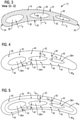
FIG. 4 is a schematic diagram illustrating construction of points representing nominal wall thickness values around measured positions of internal cooling passages in the airfoil section; -
FIG. 5 is a schematic diagram illustrating a best fit alignment of a nominal outer airfoil form to said points representing nominal wall thickness values; -
FIG. 6 is a schematic diagram illustrating a target outer airfoil form, which conforms to a final outer surface of the airfoil section after machining; and -
FIG. 7 is a schematic diagram illustrating a system for adaptively machining a cast airfoil section according to an aspect of the present invention. - In the following detailed description of the preferred embodiments, reference is made to the accompanying drawings that form a part hereof, and in which is shown by way of illustration, and not by way of limitation, a specific embodiment in which the invention may be practiced. It is to be understood that other embodiments may be utilized and that changes may be made without departing from the spirit and scope of the present invention.
- Embodiments of the present invention are illustrated in the context of a turbine blade, typically a large span blade usable in a low-pressure urbine stage of a gas turbine engine. It should be noted that aspects of the present invention may be applicable to other turbine components having an airfoil section, such as rotating blades or stationary vanes at high or low pressure turbine stages.
- Referring now to
FIG. 2 , a turbine blade 10 is illustrated, that may be produced by a casting process, for example, an investment casting process. The cast turbine blade 10 comprises anairfoil section 12 extending span-wise radially outward from aplatform 14 in relation to a rotation axis (not shown). The blade 10 further comprises aroot portion 16 extending radially inward from theplatform 14, and being configured to attach the blade 10 to a rotor disk (not shown). Referring jointly toFIG. 1 and FIG. 2 , thecast airfoil section 12 is formed of anouter wall 18 that delimits a generally hollow airfoil interior. Theouter wall 18 includes a generallyconcave pressure side 20 and a generallyconvex suction side 22, which are joined at a leadingedge 24 and at atrailing edge 26. The airfoil interior comprises one or moreinternal cooling passages 28 for radial flow of a cooling fluid. Theinternal cooling passages 28 may be defined betweeninternal partition walls 30. Theouter wall 18 comprises anouter surface 18a configured for facing a hot gas path and aninner surface 18b facing theinternal cooling passages 28. - The
internal cooling passages 28 are formed by a casting core during the investment casting process. As discussed above, during the casting process, the core may undergo deformation (e.g., rolling, rotation) and/or displacement, for example, due to differential solidification or shrinking of the metal parts. The deformations of the core may lead to changes in form and/or position of theinternal cooling passages 28, which may offset the wall thickness of theouter wall 18 from its intended thickness. Aspects of the present invention address at least the above-described problems associated with core deformation and/or displacement. - In accordance with embodiments of the present invention, the final form of the airfoil section airfoil may be formed by adaptively post-machining the outside of the airfoil section (i.e., the
outer surface 18a of the outer wall 18) beyond the casting limitation. As described herein referring toFIG. 3-6 , a method for adaptive post-machining of a cast airfoil section comprises: receiving design data pertaining to theairfoil section 12, including a nominalouter airfoil form 40N and nominal wall thickness TN data; generating a machining path by determining a targetouter airfoil form 40T, the targetouter airfoil form 40T being generated by adapting the nominalouter airfoil form 40N such that a nominal wall thickness TN is maintained at all points on theouter wall 18 around the one or moreinternal cooling passages 28 in a subsequently machined airfoil section; and machining anouter surface 18a of theairfoil section 12 produced by the casting process according to said machining path, to remove excess material to conform to the generated targetouter airfoil form 40T. The the targetouter airfoil form 40T is adapted to account for core shift (deformation and/or displacement) during the casting process, and is generated based on the prioritized consideration of the following criteria in the stated order: 1) the nominal wall thickness of theouter wall 18 around theinternal cooling passages 28, and 2) the nominal airfoil outer form. - In a first pre-machining step, subsequent to the casting process, a three-dimensional (3-D) measurement is carried out to determine an outer form of the individual cast airfoil section. The 3-D measurement may be carried out, for example, by tactile coordinate measuring machine probing, or laser scanning or photogrammetry, any combinations thereof, or by another other measurement technique to obtain 3-D geometrical data pertaining to the outer form of the cast airfoil section. The measured outer form, which is indicated by the 3-
D surface 40A inFIG. 4 , corresponds to theouter surface 18a of thecast airfoil section 12 shown inFIG. 3 . - A next step involves obtaining cooling passage position and form measurements for the
internal cooling passages 28 in relation to the measuredouter form 40A of thecast airfoil section 12. The cooling passage position and form measurements may be carried out by obtaining actual wall thickness measurements (indicated as TA) at a plurality of points along theouter wall 18 of thecast airfoil section 12, as shown inFIG. 3 . It should be noted that the measured actual wall thickness, although indicated uniformly as TA for the sake of simplicity, may vary for different points on theouter wall 12. The wall thickness measurements may be performed using ultrasound or x-ray or computed tomography or eddy current, or any other known technique. For example, in case of measurement using ultrasound, the wall thickness TA may be measured by placing a signal transmitter/probe at a point on theouter surface 18a of theouter wall 18 of theairfoil section 12 and determining a distance to a point on theinner surface 18b of theouter wall 18 from which the strongest echo signal is received. By measuring the wall thickness values at a sufficiently large number of points along the axial (chord-wise) and radial extent of theouter wall 18, a 3-D geometry 28m of the cooling passages (including form and position) may be determined in relation to the measuredouter form 40A of the cast airfoil section, as shown inFIG. 4 . - Still referring to
FIG. 4 , in a subsequent step, points 42 are constructed around the measured positions of theinternal cooling passages 28m, which represent nominal wall thickness (TN) values obtained from design data. That is, thepoints 42 are constructed at a distance equal to the nominal or design wall thickness TN from respective points on the periphery of the measuredform 28m of the internal cooling passages. Thepoints 42 may be constructed along the radial span of the cooling passages. For the sake of simplicity, the nominal thicknesses are uniformly indicated as TN. One skilled in the art would recognize that the nominal thickness values may vary for different points around the internal cooling passages, both in radial and axial (chord-wise) directions. - Next, as shown in
FIG. 5 , an iterative best fit operation is performed to align a 3-D nominal outer airfoil form 40N (obtained from design data) to thepoints 42 representing nominal wall thickness TN values. In case of an ideal casting process, all points 42 representing nominal wall thickness values would lie on the nominalouter airfoil form 40N. In the illustrated example, due to changes in angular orientation as well as relative displacement of the casting core during the casting process, at least some of thepoints 42 deviate from the nominalouter airfoil form 40N after the best fit alignment. - Next, as shown in
FIG. 6 , a targetouter airfoil form 40T is generated by adapting the nominalouter airfoil form 40N subsequent to the best fit alignment. As shown inFIG. 6 , the points representing nominal wall thickness values that deviate from the nominal outer airfoil form 40N (i.e., points that lie either inside or outside the nominal outer airfoil form 40N) after the best fit alignment are indicated as 42a, while those points representing nominal thickness values that lie on the nominal outer airfoil form 40N (or within a defined tolerance) after the best fit alignment are depicted as 42b. The targetouter airfoil form 40T is a 3-D form that is generated by adjusting the 3-D nominalouter airfoil form 40N, so that thepoints 42a that deviated from the best fit alignment of the nominalouter airfoil form 40N, now lie on the targetouter airfoil form 40T. The targetouter airfoil form 40T therefore conforms to allpoints FIG. 6 . As noted above, the targetouter airfoil form 40T is determined based on a prioritized criteria for adaptation, namely nominal wall thickness (TN) and nominal outer airfoil form (40N) obtained from design data. - The above described steps for generation of the target
outer airfoil form 40T may be implemented via a computer aided design (CAD) as described below. In the illustrated embodiment, the CAD module may be adapted for constraining the targetouter airfoil form 40T such that the targetouter airfoil form 40T does not extend beyond the measuredouter form 40A of thecast airfoil section 12. - Based on the target
outer airfoil form 40T, machining path data may be generated. The machining path data defines information for machining an outer surface of the cast airfoil section, corresponding to the measuredform 40A, to remove excess material to conform to the generated targetouter airfoil form 40T. Based on the generated machining data, the outer surface of the outer wall may be machined, for example, by grinding or milling. However, the outer wall machining may be carried out by other means, including, without limitation, electro-chemical machining (ECM) and electrical discharge machining (EDM), among others. - For post-machining of turbine blades or vanes of a given turbine row, the machining of each individual airfoil section may be adapted to fit the form of the outer airfoil surface and the internal cooling passages simultaneously. Thereby, for machining each individual airfoil section of the row of blades or vanes, a specific machining path is generated. Since the core deformations vary between individual airfoils, the machining path generation and machining execution may be adapted specific to each individual turbine airfoil.
- A further aspect of the present invention is directed to an automated system for adaptive post-machining of a cast airfoil section. As shown in
FIG. 7 , such asystem 50 may comprise asensor module 52 comprising sensors for performing 3-D measurements of the outer form of the cast airfoil section and for measuring cooling passage form and position by measurement of actual wall thickness values of the cast airfoil section, as described above. Thesystem 50 may also comprise memory means 54 containing design data, for example, in the form of a 3-D model or a CAD model of the turbine blade or vane. Thesystem 50 further comprises a CAD module configured to receivemeasurement data 62 from thesensor module 52, and design data 64 (e.g., nominal wall thickness values, nominal outer airfoil form) from thememory 54, to generate machiningpath data 66 according to the above-described method. The CAD module may be a sub-component for a computer aided design package. Themachining path data 66 generated by the CAD module may comprise a numeric control (NC) program. Thesystem 50 further comprises a machining device for machining an outer surface of the cast turbine airfoil based on themachining data 66. The CAD module may automatically set-up, check and adapt NC programs for each individual cast turbine airfoil. It will be appreciated that the CAD module may be defined in computer code and used to operate a computer to perform the above-describe method. Thus the method and articles embodying computer code suited for use to operate a computer to perform the method are independently identifiable aspects of a single inventive concept. - The above described embodiments involving adaptive machining of thin airfoils may overcome casting process limitations, thus making it possible to produce un-castable geometries, for e.g. allow production of thinner airfoils, airfoils with no or low taper, thinner trailing edges. Thinner airfoil outer walls may significantly reduce centrifugal pull loads in rotating turbine blades, particularly in low pressure turbine stages. The illustrated embodiments also allow a more cost-effective production method compared to reducing wall thickness by casting process optimization. A further benefit is the possibility to relief casting process tolerances and/or increase casting wall thickness, thus increasing casting yield and therefore reducing casting cost.
- While specific embodiments have been described in detail, those with ordinary skill in the art will appreciate that various modifications and alternative to those details could be developed in light of the overall teachings of the disclosure. Accordingly, the particular arrangements disclosed are meant to be illustrative only and not limiting as to the scope of the invention, which is to be given the full breadth of the appended claims, and any and all equivalents thereof.
- Further embodiments
- 1. A method for machining an airfoil section (12) of a turbine blade or vane produced by a casting process, the airfoil section (12) comprising an outer wall (18) delimiting an airfoil interior having one or more internal cooling passages (28), the method comprising:
- receiving design data pertaining to the airfoil section (12), including a nominal outer airfoil form (40N) and nominal wall thickness (TN) data;
- generating a machining path by determining a target outer airfoil form (40T), the target outer airfoil form (40T) being generated by adapting the nominal outer airfoil form (40N) such that a nominal wall thickness (TN) is maintained at all points on the outer wall (18) around the one or more internal cooling passages (28) in a subsequently machined airfoil section; and
- machining an outer surface (18a) of the airfoil section (12) produced by the casting process according to said machining path, to remove excess material to conform to the generated target outer airfoil form (40T).
- 2. The method according to embodiment 1, wherein determining the target outer airfoil form (40T) comprises:
- measuring a three-dimensional outer form (40A) of the airfoil section (12) after the casting process;
- obtaining cooling passage position and form measurements for the one or more internal cooling passages (28) in relation to the measured outer form (40A) of the cast airfoil section (12), the cooling passage position and form measurements being carried out by obtaining actual wall thickness (TA) measurements at a plurality of points along the outer wall (18) of the cast airfoil section (12);
- constructing points (42) representing nominal wall thickness (TN) values around the measured position (28m) of the one or more internal cooling passages (28);
- performing a best fit operation to align the nominal outer airfoil form (40N) to said points (42) representing nominal wall thickness (TN) values;
- generating the target outer airfoil form (40T) by adapting the nominal outer airfoil form (40N) subsequent to the best fit alignment, so as to conform to points (42a) representing nominal wall thickness values that still deviate from the best fit alignment of the nominal outer airfoil form (40N).
- 3. The method according to embodiment 2, further comprising constraining the target outer airfoil form (40T) such that the target outer airfoil form (40T) does not extend beyond the measured outer form (40A) of the cast airfoil section (12).
- 4. The method according to embodiment 2, wherein the measurement of a three-dimensional outer form (40A) of the airfoil section (12) is performed by tactile coordinate measuring machine probing, or laser scanning or photogrammetry, or combinations thereof.
- 5. The method according to embodiment 2, wherein the actual wall thickness (TA) measurements are performed using ultrasound or x-ray or computed tomography or eddy current, or combinations thereof.
- 6. The method according to embodiment 5, wherein the actual wall thickness measurements (TA) are performed at various points along the span-wise (radial) and chord-wise directions of the cast airfoil section (12).
- 7. The method according to embodiment 1, wherein the machining path comprises a numerical control (NC) program.
- 8. The method according to embodiment 1, wherein the machining the outer surface (18a) of the airfoil section (12) is carried out by a machining process selected from the group consisting of: grinding, milling, electro-chemical machining (ECM) and electrical discharge machining (EDM).
- 9. A method for manufacturing a row of turbine blades or vanes, comprising:
- producing a plurality turbine blades or vanes by a casting process, each blade or vane comprising an airfoil section (12) with one or more internal cooling passages;
- machining an outer surface (18a) of each airfoil section (12) subsequent to said casting process by a method according to any of embodiments 1 to 8, wherein the machining paths used for said machining are generated specific to the airfoil section (12) of each individual blade or vane.
- 10. A turbine vane or blade comprising an airfoil section, wherein the airfoil section (12) is manufactured by a casting process and subsequently machined by a method according to any of embodiments 1 to 8.
- 11. A CAD module (56) for generating machining path data for adaptively machining an airfoil section (12) of a turbine blade or vane produced by a casting process, the airfoil section (12) comprising an outer wall delimiting an airfoil interior having one or more internal cooling passages (28), wherein:
- the CAD module (56) is configured to receive design data pertaining to the airfoil section (12), including a nominal outer airfoil form (40N) and nominal wall thickness (TN) data; and
- the CAD module (56) is configured to generate machining path data by determining a target outer airfoil form (40T), wherein the CAD module (56) is configured to generate the target outer airfoil form (40T) by adapting the nominal outer airfoil form (40N) such that a nominal wall thickness (TN) is maintained at all points on the outer wall around (18) the one or more internal cooling passages (28) in a subsequently machined airfoil section,
- wherein the machining path data defines information for machining an outer surface (18a) of the airfoil section (12) produced by the casting process, to remove excess material to conform to the generated target outer airfoil form (40T).
- 12. The CAD module (56) according to embodiment 11, further wherein:
- the CAD module (56) is configured to receive three-dimensional outer form (40A) measurement data pertaining to the cast airfoil section (12);
- the CAD module (56) is configured to obtain cooling passage position and form measurements for the one or more internal cooling passages (28) in relation to the measured outer form (40A) of the cast airfoil section (12), the cooling passage position and form measurements being carried out by obtaining actual wall thickness (TA) measurements at a plurality of points along the outer wall (18) of the cast airfoil section (12);
- the CAD module (56) is adapted to construct points (42) representing nominal wall thickness (TN) values around the measured position (28m) of the one or more internal cooling passages (28);
- the CAD module (56) is adapted to perform a best fit operation to align the nominal outer airfoil form (40N) to said points (42) representing nominal wall thickness (TN) values; and
- the CAD module (56) is adapted to generate the target outer airfoil form (40T) by adapting the nominal outer airfoil form (40N) subsequent to the best fit alignment, so as to conform to points (42a) representing nominal wall thickness (TN) values that still deviate from the best fit alignment of the nominal outer airfoil form (40N).
- 13. The CAD module (56) according to
embodiment 12, further wherein:
the CAD module (56) is configured to constrain the target outer airfoil form (40T) such that the target outer airfoil form (40T) does not extend beyond the measured outer form (40A) of the cast airfoil section (12).
Claims (12)
- A method for machining an airfoil section (12) of a turbine blade or vane produced by a casting process, the airfoil section (12) comprising an outer wall (18) delimiting an airfoil interior having one or more internal cooling passages (28), the method comprising:receiving design data pertaining to the airfoil section (12), including a nominal outer airfoil form (40N) and nominal wall thickness (TN) data;generating a machining path by determining a target outer airfoil form (40T), the target outer airfoil form (40T) being generated by adapting the nominal outer airfoil form (40N) such that a nominal wall thickness (TN) is maintained at all points on the outer wall (18) around the one or more internal cooling passages (28) in a subsequently machined airfoil section,wherein determining the target outer airfoil form (40T) comprises:measuring a three-dimensional outer form (40A) of a cast airfoil section (12) subsequently to the casting process,obtaining cooling passage position and form measurements for the internal cooling passages (28) in relation to the measured outer form (40A) of the cast airfoil section (12),constructing points (42) around measured positions of the internal cooling passages (28m) which represent the nominal wall thickness (TN),performing an iterative best fit operation to align the nominal outer airfoil form (40N) to the points (42) representing nominal wall thickness (TN) values; andmachining an outer surface (18a) of the airfoil section (12) produced by the casting process according to said machining path, to remove excess material to conform to the generated target outer airfoil form (40T).
- The method according to claim 1,
wherein obtaining the cooling passage position and form measurements for the one or more internal cooling passages (28) in relation to the measured outer form (40A) of the cast airfoil section (12), the cooling passage position and form measurements being carried out by obtaining actual wall thickness (TA) measurements at a plurality of points along the outer wall (18) of the cast airfoil section (12);
wherein determining the target outer airfoil form (40T) further comprises generating the target outer airfoil form (40T) by adapting the nominal outer airfoil form (40N) subsequent to the best fit alignment, so as to conform to points (42a) representing nominal wall thickness values that still deviate from the best fit alignment of the nominal outer airfoil form (40N). - The method according to claim 2, further comprising constraining the target outer airfoil form (40T) such that the target outer airfoil form (40T) does not extend beyond the measured outer form (40A) of the cast airfoil section (12).
- The method according to claim 2, wherein the measurement of a three-dimensional outer form (40A) of the airfoil section (12) is performed by tactile coordinate measuring machine probing, or laser scanning or photogrammetry, or combinations thereof.
- The method according to claim 2, wherein the actual wall thickness (TA) measurements are performed using ultrasound or x-ray or computed tomography or eddy current, or combinations thereof.
- The method according to claim 5, wherein the actual wall thickness measurements (TA) are performed at various points along the span-wise (radial) and chord-wise directions of the cast airfoil section (12).
- The method according to claim 1, wherein the machining path comprises a numerical control (NC) program.
- The method according to claim 1, wherein the machining the outer surface (18a) of the airfoil section (12) is carried out by a machining process selected from the group consisting of: grinding, milling, electro-chemical machining (ECM) and electrical discharge machining (EDM).
- A method for manufacturing a row of turbine blades or vanes, comprising:producing a plurality turbine blades or vanes by a casting process, each blade or vane comprising an airfoil section (12) with one or more internal cooling passages;machining an outer surface (18a) of each airfoil section (12) subsequent to said casting process by a method according to any of claims 1 to 8, wherein the machining paths used for said machining are generated specific to the airfoil section (12) of each individual blade or vane.
- A CAD module (56) for generating machining path data for adaptively machining an airfoil section (12) of a turbine blade or vane produced by a casting process, the airfoil section (12) comprising an outer wall delimiting an airfoil interior having one or more internal cooling passages (28), wherein:the CAD module (56) is configured to receive design data pertaining to the airfoil section (12), including a nominal outer airfoil form (40N) and nominal wall thickness (TN) data; andthe CAD module (56) is configured to generate machining path data by determining a target outer airfoil form (40T), wherein the CAD module (56) is configured to generate the target outer airfoil form (40T) by adapting the nominal outer airfoil form (40N) such that a nominal wall thickness (TN) is maintained at all points on the outer wall around (18) the one or more internal cooling passages (28) in a subsequently machined airfoil section,wherein the CAD module is further configured to determine the target outer airfoil form (40T) by:measuring a three-dimensional outer form (40A) of a cast airfoil section (12) subsequently to the casting process,obtaining cooling passage position and form measurements for the internal cooling passages (28) in relation to the measured outer form (40A) of the cast airfoil section (12),constructing points (42) around measured positions of the internal cooling passages (28m) which represent the nominal wall thickness (TN),performing an iterative best fit operation to align the nominal outer airfoil form (40N) to the points (42) representing nominal wall thickness (TN) values, andwherein the machining path data defines information for machining an outer surface (18a) of the airfoil section (12) produced by the casting process, to remove excess material to conform to the generated target outer airfoil form (40T).
- The CAD module (56) according to claim 10, further wherein:the CAD module (56) is further configured to obtain the cooling passage position and form measurements for the one or more internal cooling passages (28) in relation to the measured outer form (40A) of the cast airfoil section (12), wherein the cooling passage position and form measurements is carried out by obtaining actual wall thickness (TA) measurements at a plurality of points along the outer wall (18) of the cast airfoil section (12);the CAD module (56) is further adapted to generate the target outer airfoil form (40T) by adapting the nominal outer airfoil form (40N) subsequent to the best fit alignment, so as to conform to points (42a) representing nominal wall thickness (TN) values that still deviate from the best fit alignment of the nominal outer airfoil form (40N).
- The CAD module (56) according to claim 11, further wherein:
the CAD module (56) is configured to constrain the target outer airfoil form (40T) such that the target outer airfoil form (40T) does not extend beyond the measured outer form (40A) of the cast airfoil section (12).
Applications Claiming Priority (3)
| Application Number | Priority Date | Filing Date | Title |
|---|---|---|---|
| US201762445956P | 2017-01-13 | 2017-01-13 | |
| PCT/US2018/013435 WO2018132629A1 (en) | 2017-01-13 | 2018-01-12 | Adaptive machining of cooled turbine airfoil |
| EP18702030.0A EP3551852B1 (en) | 2017-01-13 | 2018-01-12 | Adaptive machining of cooled turbine airfoil |
Related Parent Applications (1)
| Application Number | Title | Priority Date | Filing Date |
|---|---|---|---|
| EP18702030.0A Division EP3551852B1 (en) | 2017-01-13 | 2018-01-12 | Adaptive machining of cooled turbine airfoil |
Publications (3)
| Publication Number | Publication Date |
|---|---|
| EP3957826A2 true EP3957826A2 (en) | 2022-02-23 |
| EP3957826A3 EP3957826A3 (en) | 2022-03-23 |
| EP3957826B1 EP3957826B1 (en) | 2023-04-19 |
Family
ID=61074611
Family Applications (2)
| Application Number | Title | Priority Date | Filing Date |
|---|---|---|---|
| EP21202391.5A Active EP3957826B1 (en) | 2017-01-13 | 2018-01-12 | Adaptive machining of cooled turbine airfoil |
| EP18702030.0A Active EP3551852B1 (en) | 2017-01-13 | 2018-01-12 | Adaptive machining of cooled turbine airfoil |
Family Applications After (1)
| Application Number | Title | Priority Date | Filing Date |
|---|---|---|---|
| EP18702030.0A Active EP3551852B1 (en) | 2017-01-13 | 2018-01-12 | Adaptive machining of cooled turbine airfoil |
Country Status (5)
| Country | Link |
|---|---|
| US (1) | US11414997B2 (en) |
| EP (2) | EP3957826B1 (en) |
| JP (1) | JP6861827B2 (en) |
| CN (1) | CN110177919B (en) |
| WO (1) | WO2018132629A1 (en) |
Families Citing this family (4)
| Publication number | Priority date | Publication date | Assignee | Title |
|---|---|---|---|---|
| WO2019245532A1 (en) * | 2018-06-19 | 2019-12-26 | Siemens Aktiengesellschaft | Manufacturing method for finishing of ceramic cores flash |
| US10955815B2 (en) | 2018-11-09 | 2021-03-23 | Raytheon Technologies Corporation | Method of manufacture using autonomous adaptive machining |
| US11319814B2 (en) * | 2019-05-03 | 2022-05-03 | Raytheon Technologies Corporation | Manufacturing thin-walled castings utilizing adaptive machining |
| US20210004636A1 (en) * | 2019-07-02 | 2021-01-07 | United Technologies Corporation | Manufacturing airfoil with rounded trailing edge |
Family Cites Families (8)
| Publication number | Priority date | Publication date | Assignee | Title |
|---|---|---|---|---|
| US8506256B1 (en) | 2007-01-19 | 2013-08-13 | Florida Turbine Technologies, Inc. | Thin walled turbine blade and process for making the blade |
| EP2286956A1 (en) | 2009-08-20 | 2011-02-23 | Siemens Aktiengesellschaft | Automated repair method and system |
| JP5517587B2 (en) * | 2009-12-09 | 2014-06-11 | 三菱重工業株式会社 | Intermediate processed product of gas turbine blade, gas turbine blade and gas turbine, manufacturing method of intermediate processed product of gas turbine blade, and manufacturing method of gas turbine blade |
| US8720526B1 (en) | 2012-11-13 | 2014-05-13 | Siemens Energy, Inc. | Process for forming a long gas turbine engine blade having a main wall with a thin portion near a tip |
| SG11201505736UA (en) * | 2013-02-14 | 2015-08-28 | United Technologies Corp | Gas turbine engine component having surface indicator |
| EP2965159B1 (en) * | 2013-03-05 | 2020-05-06 | Rolls-Royce Corporation | Adaptively machining component surfaces and hole drilling |
| US9719356B2 (en) * | 2013-06-21 | 2017-08-01 | Rolls-Royce Plc | Method of finishing a blade |
| US10329916B2 (en) * | 2014-05-01 | 2019-06-25 | United Technologies Corporation | Splayed tip features for gas turbine engine airfoil |
-
2018
- 2018-01-12 EP EP21202391.5A patent/EP3957826B1/en active Active
- 2018-01-12 WO PCT/US2018/013435 patent/WO2018132629A1/en not_active Ceased
- 2018-01-12 US US16/478,004 patent/US11414997B2/en active Active
- 2018-01-12 CN CN201880006864.0A patent/CN110177919B/en active Active
- 2018-01-12 JP JP2019538164A patent/JP6861827B2/en not_active Expired - Fee Related
- 2018-01-12 EP EP18702030.0A patent/EP3551852B1/en active Active
Also Published As
| Publication number | Publication date |
|---|---|
| US20190368357A1 (en) | 2019-12-05 |
| EP3957826B1 (en) | 2023-04-19 |
| EP3957826A3 (en) | 2022-03-23 |
| US11414997B2 (en) | 2022-08-16 |
| CN110177919B (en) | 2021-08-17 |
| WO2018132629A1 (en) | 2018-07-19 |
| EP3551852B1 (en) | 2021-10-27 |
| EP3551852A1 (en) | 2019-10-16 |
| JP6861827B2 (en) | 2021-04-21 |
| JP2020505543A (en) | 2020-02-20 |
| CN110177919A (en) | 2019-08-27 |
Similar Documents
| Publication | Publication Date | Title |
|---|---|---|
| EP3957826B1 (en) | Adaptive machining of cooled turbine airfoil | |
| CN104246635B (en) | Method for machining the trailing edge of a turbine engine blade | |
| EP3255517B1 (en) | A method of manufacturing and inspecting gas washed components in a gas turbine engine | |
| JP2022510538A (en) | Automatic cooling hole identification and toolpath generation | |
| EP3255518A1 (en) | A method of manufacturing and inspecting gas washed components in a gas turbine engine | |
| US9327341B2 (en) | Method of fabricating integrally bladed rotor and stator vane assembly | |
| CN107366576A (en) | A kind of processing, detection means and the method for engine oil support plate casing | |
| EP3228825A1 (en) | Steam turbine drum nozzle having alignment feature and steam turbine | |
| EP3480426A1 (en) | Adaptively machining of a workpiece with an aerofoil shaped section | |
| US8646511B2 (en) | Component with inspection-facilitating features | |
| US8277193B1 (en) | Thin walled turbine blade and process for making the blade | |
| US11066942B2 (en) | Systems and method for determining turbine assembly flow characteristics | |
| US11619478B2 (en) | Method for the dimensional control of a turbomachine component | |
| Eret | Analysis of geometric errors of throat sizes of last stage blades in a mid-size steam turbine | |
| US8707799B2 (en) | Method for chemical milling an apparatus with a flow passage | |
| JP5517587B2 (en) | Intermediate processed product of gas turbine blade, gas turbine blade and gas turbine, manufacturing method of intermediate processed product of gas turbine blade, and manufacturing method of gas turbine blade | |
| McBean | Manufacturing technologies for key steam turbine parts | |
| US20240139892A1 (en) | A method of manufacturing a turbomachinery component | |
| US11860060B2 (en) | Integrally bladed rotor analysis and repair systems and methods | |
| EP3135427B1 (en) | Method, apparatus and computer program for repairing aerofoils of gas turbine engines | |
| McBean | Manufacturing technologies for key steam turbine components |
Legal Events
| Date | Code | Title | Description |
|---|---|---|---|
| PUAI | Public reference made under article 153(3) epc to a published international application that has entered the european phase |
Free format text: ORIGINAL CODE: 0009012 |
|
| STAA | Information on the status of an ep patent application or granted ep patent |
Free format text: STATUS: THE APPLICATION HAS BEEN PUBLISHED |
|
| PUAL | Search report despatched |
Free format text: ORIGINAL CODE: 0009013 |
|
| AC | Divisional application: reference to earlier application |
Ref document number: 3551852 Country of ref document: EP Kind code of ref document: P |
|
| AK | Designated contracting states |
Kind code of ref document: A2 Designated state(s): AL AT BE BG CH CY CZ DE DK EE ES FI FR GB GR HR HU IE IS IT LI LT LU LV MC MK MT NL NO PL PT RO RS SE SI SK SM TR |
|
| AK | Designated contracting states |
Kind code of ref document: A3 Designated state(s): AL AT BE BG CH CY CZ DE DK EE ES FI FR GB GR HR HU IE IS IT LI LT LU LV MC MK MT NL NO PL PT RO RS SE SI SK SM TR |
|
| RIC1 | Information provided on ipc code assigned before grant |
Ipc: F01D 5/18 20060101AFI20220215BHEP |
|
| STAA | Information on the status of an ep patent application or granted ep patent |
Free format text: STATUS: REQUEST FOR EXAMINATION WAS MADE |
|
| 17P | Request for examination filed |
Effective date: 20220428 |
|
| RBV | Designated contracting states (corrected) |
Designated state(s): AL AT BE BG CH CY CZ DE DK EE ES FI FR GB GR HR HU IE IS IT LI LT LU LV MC MK MT NL NO PL PT RO RS SE SI SK SM TR |
|
| GRAP | Despatch of communication of intention to grant a patent |
Free format text: ORIGINAL CODE: EPIDOSNIGR1 |
|
| STAA | Information on the status of an ep patent application or granted ep patent |
Free format text: STATUS: GRANT OF PATENT IS INTENDED |
|
| INTG | Intention to grant announced |
Effective date: 20221116 |
|
| GRAS | Grant fee paid |
Free format text: ORIGINAL CODE: EPIDOSNIGR3 |
|
| GRAA | (expected) grant |
Free format text: ORIGINAL CODE: 0009210 |
|
| STAA | Information on the status of an ep patent application or granted ep patent |
Free format text: STATUS: THE PATENT HAS BEEN GRANTED |
|
| AC | Divisional application: reference to earlier application |
Ref document number: 3551852 Country of ref document: EP Kind code of ref document: P |
|
| AK | Designated contracting states |
Kind code of ref document: B1 Designated state(s): AL AT BE BG CH CY CZ DE DK EE ES FI FR GB GR HR HU IE IS IT LI LT LU LV MC MK MT NL NO PL PT RO RS SE SI SK SM TR |
|
| REG | Reference to a national code |
Ref country code: GB Ref legal event code: FG4D |
|
| REG | Reference to a national code |
Ref country code: DE Ref legal event code: R096 Ref document number: 602018048798 Country of ref document: DE |
|
| REG | Reference to a national code |
Ref country code: CH Ref legal event code: EP |
|
| REG | Reference to a national code |
Ref country code: IE Ref legal event code: FG4D |
|
| REG | Reference to a national code |
Ref country code: AT Ref legal event code: REF Ref document number: 1561309 Country of ref document: AT Kind code of ref document: T Effective date: 20230515 |
|
| REG | Reference to a national code |
Ref country code: LT Ref legal event code: MG9D |
|
| REG | Reference to a national code |
Ref country code: NL Ref legal event code: MP Effective date: 20230419 |
|
| REG | Reference to a national code |
Ref country code: AT Ref legal event code: MK05 Ref document number: 1561309 Country of ref document: AT Kind code of ref document: T Effective date: 20230419 |
|
| PG25 | Lapsed in a contracting state [announced via postgrant information from national office to epo] |
Ref country code: NL Free format text: LAPSE BECAUSE OF FAILURE TO SUBMIT A TRANSLATION OF THE DESCRIPTION OR TO PAY THE FEE WITHIN THE PRESCRIBED TIME-LIMIT Effective date: 20230419 |
|
| PG25 | Lapsed in a contracting state [announced via postgrant information from national office to epo] |
Ref country code: SE Free format text: LAPSE BECAUSE OF FAILURE TO SUBMIT A TRANSLATION OF THE DESCRIPTION OR TO PAY THE FEE WITHIN THE PRESCRIBED TIME-LIMIT Effective date: 20230419 Ref country code: PT Free format text: LAPSE BECAUSE OF FAILURE TO SUBMIT A TRANSLATION OF THE DESCRIPTION OR TO PAY THE FEE WITHIN THE PRESCRIBED TIME-LIMIT Effective date: 20230821 Ref country code: NO Free format text: LAPSE BECAUSE OF FAILURE TO SUBMIT A TRANSLATION OF THE DESCRIPTION OR TO PAY THE FEE WITHIN THE PRESCRIBED TIME-LIMIT Effective date: 20230719 Ref country code: ES Free format text: LAPSE BECAUSE OF FAILURE TO SUBMIT A TRANSLATION OF THE DESCRIPTION OR TO PAY THE FEE WITHIN THE PRESCRIBED TIME-LIMIT Effective date: 20230419 Ref country code: AT Free format text: LAPSE BECAUSE OF FAILURE TO SUBMIT A TRANSLATION OF THE DESCRIPTION OR TO PAY THE FEE WITHIN THE PRESCRIBED TIME-LIMIT Effective date: 20230419 |
|
| PG25 | Lapsed in a contracting state [announced via postgrant information from national office to epo] |
Ref country code: RS Free format text: LAPSE BECAUSE OF FAILURE TO SUBMIT A TRANSLATION OF THE DESCRIPTION OR TO PAY THE FEE WITHIN THE PRESCRIBED TIME-LIMIT Effective date: 20230419 Ref country code: PL Free format text: LAPSE BECAUSE OF FAILURE TO SUBMIT A TRANSLATION OF THE DESCRIPTION OR TO PAY THE FEE WITHIN THE PRESCRIBED TIME-LIMIT Effective date: 20230419 Ref country code: LV Free format text: LAPSE BECAUSE OF FAILURE TO SUBMIT A TRANSLATION OF THE DESCRIPTION OR TO PAY THE FEE WITHIN THE PRESCRIBED TIME-LIMIT Effective date: 20230419 Ref country code: LT Free format text: LAPSE BECAUSE OF FAILURE TO SUBMIT A TRANSLATION OF THE DESCRIPTION OR TO PAY THE FEE WITHIN THE PRESCRIBED TIME-LIMIT Effective date: 20230419 Ref country code: IS Free format text: LAPSE BECAUSE OF FAILURE TO SUBMIT A TRANSLATION OF THE DESCRIPTION OR TO PAY THE FEE WITHIN THE PRESCRIBED TIME-LIMIT Effective date: 20230819 Ref country code: HR Free format text: LAPSE BECAUSE OF FAILURE TO SUBMIT A TRANSLATION OF THE DESCRIPTION OR TO PAY THE FEE WITHIN THE PRESCRIBED TIME-LIMIT Effective date: 20230419 Ref country code: GR Free format text: LAPSE BECAUSE OF FAILURE TO SUBMIT A TRANSLATION OF THE DESCRIPTION OR TO PAY THE FEE WITHIN THE PRESCRIBED TIME-LIMIT Effective date: 20230720 Ref country code: AL Free format text: LAPSE BECAUSE OF FAILURE TO SUBMIT A TRANSLATION OF THE DESCRIPTION OR TO PAY THE FEE WITHIN THE PRESCRIBED TIME-LIMIT Effective date: 20230419 |
|
| PG25 | Lapsed in a contracting state [announced via postgrant information from national office to epo] |
Ref country code: FI Free format text: LAPSE BECAUSE OF FAILURE TO SUBMIT A TRANSLATION OF THE DESCRIPTION OR TO PAY THE FEE WITHIN THE PRESCRIBED TIME-LIMIT Effective date: 20230419 |
|
| PG25 | Lapsed in a contracting state [announced via postgrant information from national office to epo] |
Ref country code: SK Free format text: LAPSE BECAUSE OF FAILURE TO SUBMIT A TRANSLATION OF THE DESCRIPTION OR TO PAY THE FEE WITHIN THE PRESCRIBED TIME-LIMIT Effective date: 20230419 |
|
| REG | Reference to a national code |
Ref country code: DE Ref legal event code: R097 Ref document number: 602018048798 Country of ref document: DE |
|
| PG25 | Lapsed in a contracting state [announced via postgrant information from national office to epo] |
Ref country code: SM Free format text: LAPSE BECAUSE OF FAILURE TO SUBMIT A TRANSLATION OF THE DESCRIPTION OR TO PAY THE FEE WITHIN THE PRESCRIBED TIME-LIMIT Effective date: 20230419 Ref country code: SK Free format text: LAPSE BECAUSE OF FAILURE TO SUBMIT A TRANSLATION OF THE DESCRIPTION OR TO PAY THE FEE WITHIN THE PRESCRIBED TIME-LIMIT Effective date: 20230419 Ref country code: RO Free format text: LAPSE BECAUSE OF FAILURE TO SUBMIT A TRANSLATION OF THE DESCRIPTION OR TO PAY THE FEE WITHIN THE PRESCRIBED TIME-LIMIT Effective date: 20230419 Ref country code: EE Free format text: LAPSE BECAUSE OF FAILURE TO SUBMIT A TRANSLATION OF THE DESCRIPTION OR TO PAY THE FEE WITHIN THE PRESCRIBED TIME-LIMIT Effective date: 20230419 Ref country code: DK Free format text: LAPSE BECAUSE OF FAILURE TO SUBMIT A TRANSLATION OF THE DESCRIPTION OR TO PAY THE FEE WITHIN THE PRESCRIBED TIME-LIMIT Effective date: 20230419 Ref country code: CZ Free format text: LAPSE BECAUSE OF FAILURE TO SUBMIT A TRANSLATION OF THE DESCRIPTION OR TO PAY THE FEE WITHIN THE PRESCRIBED TIME-LIMIT Effective date: 20230419 |
|
| PLBE | No opposition filed within time limit |
Free format text: ORIGINAL CODE: 0009261 |
|
| STAA | Information on the status of an ep patent application or granted ep patent |
Free format text: STATUS: NO OPPOSITION FILED WITHIN TIME LIMIT |
|
| 26N | No opposition filed |
Effective date: 20240122 |
|
| PG25 | Lapsed in a contracting state [announced via postgrant information from national office to epo] |
Ref country code: SI Free format text: LAPSE BECAUSE OF FAILURE TO SUBMIT A TRANSLATION OF THE DESCRIPTION OR TO PAY THE FEE WITHIN THE PRESCRIBED TIME-LIMIT Effective date: 20230419 |
|
| PG25 | Lapsed in a contracting state [announced via postgrant information from national office to epo] |
Ref country code: SI Free format text: LAPSE BECAUSE OF FAILURE TO SUBMIT A TRANSLATION OF THE DESCRIPTION OR TO PAY THE FEE WITHIN THE PRESCRIBED TIME-LIMIT Effective date: 20230419 |
|
| PG25 | Lapsed in a contracting state [announced via postgrant information from national office to epo] |
Ref country code: MC Free format text: LAPSE BECAUSE OF FAILURE TO SUBMIT A TRANSLATION OF THE DESCRIPTION OR TO PAY THE FEE WITHIN THE PRESCRIBED TIME-LIMIT Effective date: 20230419 |
|
| PG25 | Lapsed in a contracting state [announced via postgrant information from national office to epo] |
Ref country code: MC Free format text: LAPSE BECAUSE OF FAILURE TO SUBMIT A TRANSLATION OF THE DESCRIPTION OR TO PAY THE FEE WITHIN THE PRESCRIBED TIME-LIMIT Effective date: 20230419 |
|
| PG25 | Lapsed in a contracting state [announced via postgrant information from national office to epo] |
Ref country code: LU Free format text: LAPSE BECAUSE OF NON-PAYMENT OF DUE FEES Effective date: 20240112 |
|
| GBPC | Gb: european patent ceased through non-payment of renewal fee |
Effective date: 20240112 |
|
| PG25 | Lapsed in a contracting state [announced via postgrant information from national office to epo] |
Ref country code: LU Free format text: LAPSE BECAUSE OF NON-PAYMENT OF DUE FEES Effective date: 20240112 |
|
| PG25 | Lapsed in a contracting state [announced via postgrant information from national office to epo] |
Ref country code: GB Free format text: LAPSE BECAUSE OF NON-PAYMENT OF DUE FEES Effective date: 20240112 |
|
| PG25 | Lapsed in a contracting state [announced via postgrant information from national office to epo] |
Ref country code: BE Free format text: LAPSE BECAUSE OF NON-PAYMENT OF DUE FEES Effective date: 20240131 |
|
| PG25 | Lapsed in a contracting state [announced via postgrant information from national office to epo] |
Ref country code: FR Free format text: LAPSE BECAUSE OF NON-PAYMENT OF DUE FEES Effective date: 20240131 |
|
| PG25 | Lapsed in a contracting state [announced via postgrant information from national office to epo] |
Ref country code: GB Free format text: LAPSE BECAUSE OF NON-PAYMENT OF DUE FEES Effective date: 20240112 Ref country code: FR Free format text: LAPSE BECAUSE OF NON-PAYMENT OF DUE FEES Effective date: 20240131 Ref country code: BE Free format text: LAPSE BECAUSE OF NON-PAYMENT OF DUE FEES Effective date: 20240131 |
|
| REG | Reference to a national code |
Ref country code: BE Ref legal event code: MM Effective date: 20240131 |
|
| PG25 | Lapsed in a contracting state [announced via postgrant information from national office to epo] |
Ref country code: BG Free format text: LAPSE BECAUSE OF FAILURE TO SUBMIT A TRANSLATION OF THE DESCRIPTION OR TO PAY THE FEE WITHIN THE PRESCRIBED TIME-LIMIT Effective date: 20230419 |
|
| PG25 | Lapsed in a contracting state [announced via postgrant information from national office to epo] |
Ref country code: BG Free format text: LAPSE BECAUSE OF FAILURE TO SUBMIT A TRANSLATION OF THE DESCRIPTION OR TO PAY THE FEE WITHIN THE PRESCRIBED TIME-LIMIT Effective date: 20230419 |
|
| PG25 | Lapsed in a contracting state [announced via postgrant information from national office to epo] |
Ref country code: IE Free format text: LAPSE BECAUSE OF NON-PAYMENT OF DUE FEES Effective date: 20240112 |
|
| PG25 | Lapsed in a contracting state [announced via postgrant information from national office to epo] |
Ref country code: IE Free format text: LAPSE BECAUSE OF NON-PAYMENT OF DUE FEES Effective date: 20240112 |
|
| PG25 | Lapsed in a contracting state [announced via postgrant information from national office to epo] |
Ref country code: CY Free format text: LAPSE BECAUSE OF FAILURE TO SUBMIT A TRANSLATION OF THE DESCRIPTION OR TO PAY THE FEE WITHIN THE PRESCRIBED TIME-LIMIT; INVALID AB INITIO Effective date: 20180112 |
|
| PG25 | Lapsed in a contracting state [announced via postgrant information from national office to epo] |
Ref country code: HU Free format text: LAPSE BECAUSE OF FAILURE TO SUBMIT A TRANSLATION OF THE DESCRIPTION OR TO PAY THE FEE WITHIN THE PRESCRIBED TIME-LIMIT; INVALID AB INITIO Effective date: 20180112 |
|
| PG25 | Lapsed in a contracting state [announced via postgrant information from national office to epo] |
Ref country code: TR Free format text: LAPSE BECAUSE OF FAILURE TO SUBMIT A TRANSLATION OF THE DESCRIPTION OR TO PAY THE FEE WITHIN THE PRESCRIBED TIME-LIMIT Effective date: 20230419 |
|
| REG | Reference to a national code |
Ref country code: CH Ref legal event code: U11 Free format text: ST27 STATUS EVENT CODE: U-0-0-U10-U11 (AS PROVIDED BY THE NATIONAL OFFICE) Effective date: 20260201 |
|
| PGFP | Annual fee paid to national office [announced via postgrant information from national office to epo] |
Ref country code: DE Payment date: 20260127 Year of fee payment: 9 |
|
| PGFP | Annual fee paid to national office [announced via postgrant information from national office to epo] |
Ref country code: IT Payment date: 20260123 Year of fee payment: 9 |
|
| PGFP | Annual fee paid to national office [announced via postgrant information from national office to epo] |
Ref country code: CH Payment date: 20260201 Year of fee payment: 9 |