EP3957592A1 - Elevator cab air purification - Google Patents
Elevator cab air purification Download PDFInfo
- Publication number
- EP3957592A1 EP3957592A1 EP21191534.3A EP21191534A EP3957592A1 EP 3957592 A1 EP3957592 A1 EP 3957592A1 EP 21191534 A EP21191534 A EP 21191534A EP 3957592 A1 EP3957592 A1 EP 3957592A1
- Authority
- EP
- European Patent Office
- Prior art keywords
- housing
- air
- pathway
- air flow
- outlet
- Prior art date
- Legal status (The legal status is an assumption and is not a legal conclusion. Google has not performed a legal analysis and makes no representation as to the accuracy of the status listed.)
- Withdrawn
Links
- 238000004887 air purification Methods 0.000 title claims abstract description 21
- 230000037361 pathway Effects 0.000 claims abstract description 76
- 230000005855 radiation Effects 0.000 claims description 21
- 238000000034 method Methods 0.000 claims description 17
- 230000001678 irradiating effect Effects 0.000 claims description 7
- 239000000356 contaminant Substances 0.000 description 5
- 229920001296 polysiloxane Polymers 0.000 description 2
- 238000000746 purification Methods 0.000 description 2
- 230000007704 transition Effects 0.000 description 2
- 241001678559 COVID-19 virus Species 0.000 description 1
- 208000035473 Communicable disease Diseases 0.000 description 1
- 244000000022 airborne pathogen Species 0.000 description 1
- WYTGDNHDOZPMIW-RCBQFDQVSA-N alstonine Natural products C1=CC2=C3C=CC=CC3=NC2=C2N1C[C@H]1[C@H](C)OC=C(C(=O)OC)[C@H]1C2 WYTGDNHDOZPMIW-RCBQFDQVSA-N 0.000 description 1
- 230000015556 catabolic process Effects 0.000 description 1
- 238000006731 degradation reaction Methods 0.000 description 1
- 239000000463 material Substances 0.000 description 1
- 238000012986 modification Methods 0.000 description 1
- 230000004048 modification Effects 0.000 description 1
- 238000004806 packaging method and process Methods 0.000 description 1
- 239000002245 particle Substances 0.000 description 1
- 244000052769 pathogen Species 0.000 description 1
Images

Classifications
-
- F—MECHANICAL ENGINEERING; LIGHTING; HEATING; WEAPONS; BLASTING
- F24—HEATING; RANGES; VENTILATING
- F24F—AIR-CONDITIONING; AIR-HUMIDIFICATION; VENTILATION; USE OF AIR CURRENTS FOR SCREENING
- F24F7/00—Ventilation
- F24F7/007—Ventilation with forced flow
-
- B—PERFORMING OPERATIONS; TRANSPORTING
- B66—HOISTING; LIFTING; HAULING
- B66B—ELEVATORS; ESCALATORS OR MOVING WALKWAYS
- B66B11/00—Main component parts of lifts in, or associated with, buildings or other structures
- B66B11/02—Cages, i.e. cars
- B66B11/0226—Constructional features, e.g. walls assembly, decorative panels, comfort equipment, thermal or sound insulation
- B66B11/024—Ventilation systems
-
- F—MECHANICAL ENGINEERING; LIGHTING; HEATING; WEAPONS; BLASTING
- F24—HEATING; RANGES; VENTILATING
- F24F—AIR-CONDITIONING; AIR-HUMIDIFICATION; VENTILATION; USE OF AIR CURRENTS FOR SCREENING
- F24F7/00—Ventilation
- F24F7/003—Ventilation in combination with air cleaning
-
- F—MECHANICAL ENGINEERING; LIGHTING; HEATING; WEAPONS; BLASTING
- F24—HEATING; RANGES; VENTILATING
- F24F—AIR-CONDITIONING; AIR-HUMIDIFICATION; VENTILATION; USE OF AIR CURRENTS FOR SCREENING
- F24F8/00—Treatment, e.g. purification, of air supplied to human living or working spaces otherwise than by heating, cooling, humidifying or drying
- F24F8/20—Treatment, e.g. purification, of air supplied to human living or working spaces otherwise than by heating, cooling, humidifying or drying by sterilisation
- F24F8/22—Treatment, e.g. purification, of air supplied to human living or working spaces otherwise than by heating, cooling, humidifying or drying by sterilisation using UV light
-
- F—MECHANICAL ENGINEERING; LIGHTING; HEATING; WEAPONS; BLASTING
- F24—HEATING; RANGES; VENTILATING
- F24F—AIR-CONDITIONING; AIR-HUMIDIFICATION; VENTILATION; USE OF AIR CURRENTS FOR SCREENING
- F24F3/00—Air-conditioning systems in which conditioned primary air is supplied from one or more central stations to distributing units in the rooms or spaces where it may receive secondary treatment; Apparatus specially designed for such systems
- F24F3/12—Air-conditioning systems in which conditioned primary air is supplied from one or more central stations to distributing units in the rooms or spaces where it may receive secondary treatment; Apparatus specially designed for such systems characterised by the treatment of the air otherwise than by heating and cooling
- F24F3/16—Air-conditioning systems in which conditioned primary air is supplied from one or more central stations to distributing units in the rooms or spaces where it may receive secondary treatment; Apparatus specially designed for such systems characterised by the treatment of the air otherwise than by heating and cooling by purification, e.g. by filtering; by sterilisation; by ozonisation
- F24F3/167—Clean rooms, i.e. enclosed spaces in which a uniform flow of filtered air is distributed
-
- F—MECHANICAL ENGINEERING; LIGHTING; HEATING; WEAPONS; BLASTING
- F24—HEATING; RANGES; VENTILATING
- F24F—AIR-CONDITIONING; AIR-HUMIDIFICATION; VENTILATION; USE OF AIR CURRENTS FOR SCREENING
- F24F8/00—Treatment, e.g. purification, of air supplied to human living or working spaces otherwise than by heating, cooling, humidifying or drying
- F24F8/10—Treatment, e.g. purification, of air supplied to human living or working spaces otherwise than by heating, cooling, humidifying or drying by separation, e.g. by filtering
- F24F8/192—Treatment, e.g. purification, of air supplied to human living or working spaces otherwise than by heating, cooling, humidifying or drying by separation, e.g. by filtering by electrical means, e.g. by applying electrostatic fields or high voltages
Definitions
- Elevator systems typically include a cab for carrying passengers among various levels within a building.
- Many elevator cabs include a device for exchanging air between the interior of the cab and the hoistway.
- Such devices typically are limited in the amount of air flow or exchange that can be achieved.
- the limited air circulation provided by such devices and the unconditioned hoistway air typically inhibit such devices from easily addressing concerns about the purity of air in an elevator cab.
- An illustrative example embodiment of an elevator cab air purification device includes a housing having an inlet, an outlet, and at least one air pathway between the inlet and the outlet.
- a fan module is situated to cause air flow into the housing through the inlet, through the housing, and out of the housing through the outlet.
- the air flow through the housing includes air flow along the at least one pathway in at least a first direction.
- An air purifier is situated within the housing and configured to purify air that flows along the at least one pathway before the air exits the housing through the outlet.
- the air purifier comprises a source of radiation.
- the source of radiation comprises a light that emits ultraviolet light.
- the at least one pathway includes a plurality of pathways, airflow along at least one of the pathways is in a second direction that is different than the first direction, and each of the pathways includes the source of radiation along at least portion of a length of the pathway.
- the first direction is opposite the second direction.
- the elevator cab includes a plurality of vertically oriented walls between a floor and a ceiling, the housing is situated parallel to and against at least one of the walls, the first direction corresponds to air flow away from the ceiling and toward the floor, and the second direction corresponds to air flow away from the floor and toward the ceiling.
- the housing includes a plurality of baffles that define the pathways within the housing.
- the fan module comprises a plurality of fans, and at least one of the plurality of fans is situated in a different location of the housing than at least one others of the plurality of fans.
- the housing is configured to be situated against a corner of an interior of the elevator cab.
- the housing is configured as a portion of an interior cab wall, a raised panel or a cabinet.
- An illustrative example embodiment of a method of purifying air in an elevator cab uses a housing having an inlet, an outlet, and at least one air pathway between the inlet and the outlet.
- the method includes: causing air flow into the housing through the inlet, through the housing, and out of the housing through the outlet, wherein the air flow through the housing includes air flow along the at least one pathway in at least a first direction; and purifying air that flows along the at least one pathway before the air exits the housing through the outlet.
- purifying the air comprises irradiating the air.
- irradiating the air comprises exposing the air to ultraviolet light.
- the at least one pathway comprises a plurality of pathways
- airflow along at least one other of the pathways is in a second direction different from the first direction
- irradiating the air comprises exposing the air flow along each of the pathways to a light that emits the radiation along at least portion of a length of the pathway.
- the first direction is opposite the second direction.
- the elevator cab includes a plurality of vertically oriented walls between a floor and a ceiling, the housing is situated parallel to and against at least one of the walls, the first direction corresponds to air flow away from the ceiling and toward the floor, and the second direction corresponds to air flow away from the floor and toward the ceiling.
- the housing includes a plurality of baffles that define the pathways within the housing.
- causing the air flow comprises using a fan module, the fan module comprises a plurality of fans, and at least one of the plurality of fans is situated in a different location of the housing than at least one others of the plurality of fans.
- the housing is configured to be situated against a corner of an interior of the elevator cab.
- the housing is configured as a portion of an interior cab wall, a raised panel or a cabinet.
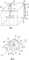
- FIG 1 diagrammatically illustrates selected portions of an elevator cab 20.
- a plurality of air purification devices 22 are situated within the elevator cab 20.
- Each of the exemplary air purification devices 22 includes a housing 24 having an inlet 26 and an outlet 28.
- a fan module 30 causes airflow into the inlet 26, through a plurality of pathways within the housing 24 and out of the housing 24 through the outlet 28.
- the illustrated position of the fan module shown in Figure 1 is for ease of illustration and not limiting in any way.
- the fan module 30 includes at least one fan. Multiple fans may be positioned in different locations along the housing 24 to achieve a desired airflow.
- air is drawn into the inlet 26 from near a ceiling of the elevator cab 22 as schematically represented by the arrows 32. Airflow exiting the outlet 28 is directed generally toward a floor of the elevator cab 20 as schematically shown by the arrows 34.
- the inlet 26 is located near the ceiling of the elevator cab 20 and the outlet 28 is located near the floor of the elevator cab 20 to take advantage of natural air convection within the elevator cab 20.
- the air purification devices 22 in this example embodiment are configured to be received in a corner of the interior of the elevator cab 20.
- the housings 24 in this example include two sides configured to be received against and secured to the two walls that meet at the corresponding corner of the elevator cab 20.
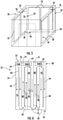
- Other embodiments, such as that shown in Figure 5 include housings that are configured to be situated along and secured to a wall of the elevator cab 20.
- the number and size of air purification devices 22 may vary to achieve sufficient purification for a particular cab size or expected occupancy during use.
- the airflow arrows that are in broken lines represent airflow near a bottom of the housing 24 and the solid-line arrows represents airflow near a top of the housing 24.
- the housing includes a first pathway 40 extending from the inlet 26 toward a bottom of the housing 24. The air moves downward along the first pathway 40 in a downward direction (e.g., into the page in Figure 2 ). Airflow leaves the first pathway 40 and continues along a second pathway 42 as schematically represented by the arrow 44. Airflow through the second pathway 42 is in an upward direction (e.g., out of the page according to Figure 2 ).
- the airflow continues as shown at 46 from the second pathway 42 into a third pathway 48.
- the air flows downward through the third pathway 48 and eventually transitions as shown by the arrow 50 into a fourth pathway 52.
- Airflow through the fourth pathway 52 is in an upward direction.
- the airflow eventually transitions as represented by the arrow 54 into a fifth pathway 56 from which it eventually exits the housing 24 through the outlet 28 as represented by the arrow 34.
- Each of the pathways 40, 42, 48, 52 and 56 includes an air purifier that may comprise various features or components, such as a filter or a source of radiation.
- the illustrated example embodiments include a source of radiation 60 as the air purifier.
- the source of radiation 60 irradiates the air flowing along the pathway.
- the sources of radiation 60 are situated to irradiate the air within each pathway to purify the air.
- purified air has at least some contaminants removed from it. Air is purified even if less than all particles or contaminants are removed from the air. In other words, purified air is not necessarily absolutely pure but has a lower level of concentration of at least one type of contaminant compared to air that has not been purified by the purification device 22.
- the sources of radiation 60 emit ultraviolet light so that air flowing along each pathway is irradiated by the ultraviolet radiation.
- the sources of ultraviolet light include a plurality of light emitting diodes (LEDs).
- a flexible ribbon made of a silicone material supports a plurality of LEDs that emit ultraviolet light along the corresponding pathway within the housing 24.
- a silicone-based support for the LEDs is not subject to ultraviolet degradation and provides a small packaging envelope so that a useful amount of ultraviolet radiation affects the airflow in each passageway without requiring the air purification device 22 to take up a significant amount of space within the interior of the elevator cab 20.
- the housing 24 retains the ultraviolet light or other purifying radiation and prevents it from emanating into the interior of the elevator cab. Only the air flowing along the pathways of the air purification device 22 is exposed to that radiation.
- FIGS 3 and 4 show an example configuration of a fan module 30.
- the fan module includes a plurality of fans 64 that draw air in through louver openings 66 of the inlet 26.
- the fans 64 then propel air or cause airflow as represented by the arrows 68 into at least one pathway within the housing 24.
- Other embodiments include a single fan that is capable of establishing the desired airflow throughout the entire air purification device 22.
- Raised panels 70 are provided for aesthetic purposes within the interior of the elevator cab 20.
- the air purification devices 22 in this example are configured to appear like raised panels, resembling the aesthetic raised panels 70.
- the housing 24 is configured as a raised panel or a relatively thin cabinet that is supported on a wall of the elevator cab 20.
- a plurality of baffles 74 are situated within the housing 24 to establish a plurality of airflow pathways.
- the fan module 30 includes multiple fans 64. At least one of the fans 64 draws air into the inlet 26 and causes airflow along a first pathway 76 as represented by the arrows 78.
- a source of radiation 60 such as a strip of LEDs is situated along a substantial portion of the length of the pathway 76 for irradiating the air flowing along the pathway 76.
- the first pathway 76 in this example ends near a bottom of the housing 24 where the airflow continues around an end of the corresponding baffle 74 into a second pathway 80 that includes its own source of radiation 60.
- the airflow through the second pathway 80 in this example is in an upward direction away from the floor of the elevator cab and toward the ceiling of the elevator cab.
- a third pathway 84 receives continued airflow that moves through the third pathway 84 in a downward direction as directed by the arrows 86.
- a fourth pathway 88 accommodates airflow as represented by the arrows 90 and a fifth pathway 92 accommodates airflow as represented by the arrows 94 toward the outlet 28 where the purified air exists the housing 24 as represented by the arrow 34.
- the fans 64 of the fan module 30 are situated at various locations of the housing 24 in this example to achieve a desired air flow rate through the pathways.
- the fans 64 operate to establish a flow rate that ensures a desired amount of time that the air is exposed to the ultraviolet radiation to reduce or eliminate contaminants or pathogens in the air.
- the plurality of pathways and the different directions of airflow along those pathways provides a substantial enough time of exposure of the air to the ultraviolet radiation for effectively purifying the air flowing through the housing 24.
- the air purification devices 24 are taller than they are wide and, therefore, the airflow pathways are oriented in a vertical direction and the airflow is directed vertically between the ceiling and the floor in opposite directions along adjacent pathways.
- a serpentine arrangement of pathways in a generally horizontal orientation within a housing 24 accommodates airflow for a sufficient amount of time to provide adequate exposure to ultraviolet radiation for purifying the air.
- the embodiments described above can be retrofit into existing elevator cabs without disrupting the aesthetic of the interior of the cab. Those and other embodiments are useful for new cabs or fully renovated cab interiors. Some embodiments intended to be incorporated into a new cab or new cab interior include a housing that extends from the decorative ceiling area to the kickplate area.
- the air purification device is embedded into the exterior of the shell, in a fashion similar to arrangement of the embodiment shown in Figures 5 and 6 .
- the air purification device of such embodiments is embedded into the shell panel, itself.
- Air purification devices 22 like those in the disclosed example embodiments, facilitate purifying air within an elevator cab 20. Such devices are useful, for example to reduce or eliminate airborne pathogens or contaminants, such as the COVID-19 virus or other communicable diseases.
- the air purification devices 22 fit within an elevator cab 20 in a manner that does not reduce the passenger-carrying capacity in most instances.
- the air purification devices 22 can be incorporated into the interior of an elevator cab 20 without disrupting the aesthetics of the cab interior.
Landscapes
- Engineering & Computer Science (AREA)
- Mechanical Engineering (AREA)
- Chemical & Material Sciences (AREA)
- Combustion & Propulsion (AREA)
- General Engineering & Computer Science (AREA)
- Civil Engineering (AREA)
- Structural Engineering (AREA)
- Cage And Drive Apparatuses For Elevators (AREA)
- Disinfection, Sterilisation Or Deodorisation Of Air (AREA)
Abstract
Description
- Elevator systems typically include a cab for carrying passengers among various levels within a building. Many elevator cabs include a device for exchanging air between the interior of the cab and the hoistway. Such devices typically are limited in the amount of air flow or exchange that can be achieved. The limited air circulation provided by such devices and the unconditioned hoistway air typically inhibit such devices from easily addressing concerns about the purity of air in an elevator cab.
- An illustrative example embodiment of an elevator cab air purification device includes a housing having an inlet, an outlet, and at least one air pathway between the inlet and the outlet. A fan module is situated to cause air flow into the housing through the inlet, through the housing, and out of the housing through the outlet. The air flow through the housing includes air flow along the at least one pathway in at least a first direction. An air purifier is situated within the housing and configured to purify air that flows along the at least one pathway before the air exits the housing through the outlet.
- In an example embodiment having at least one feature of the device of the previous paragraph, the air purifier comprises a source of radiation.
- In an example embodiment having at least one feature of the device of the any of the previous paragraphs, the source of radiation comprises a light that emits ultraviolet light.
- In an example embodiment having at least one feature of the device of the any of the previous paragraphs, the at least one pathway includes a plurality of pathways, airflow along at least one of the pathways is in a second direction that is different than the first direction, and each of the pathways includes the source of radiation along at least portion of a length of the pathway.
- In an example embodiment having at least one feature of the device of the any of the previous paragraphs, the first direction is opposite the second direction.
- In an example embodiment having at least one feature of the device of the any of the previous paragraphs, the elevator cab includes a plurality of vertically oriented walls between a floor and a ceiling, the housing is situated parallel to and against at least one of the walls, the first direction corresponds to air flow away from the ceiling and toward the floor, and the second direction corresponds to air flow away from the floor and toward the ceiling.
- In an example embodiment having at least one feature of the device of the any of the previous paragraphs, the housing includes a plurality of baffles that define the pathways within the housing.
- In an example embodiment having at least one feature of the device of the any of the previous paragraphs, the fan module comprises a plurality of fans, and at least one of the plurality of fans is situated in a different location of the housing than at least one others of the plurality of fans.
- In an example embodiment having at least one feature of the device of the any of the previous paragraphs, the housing is configured to be situated against a corner of an interior of the elevator cab.
- In an example embodiment having at least one feature of the device of the any of the previous paragraphs, the housing is configured as a portion of an interior cab wall, a raised panel or a cabinet.
- An illustrative example embodiment of a method of purifying air in an elevator cab uses a housing having an inlet, an outlet, and at least one air pathway between the inlet and the outlet. The method includes: causing air flow into the housing through the inlet, through the housing, and out of the housing through the outlet, wherein the air flow through the housing includes air flow along the at least one pathway in at least a first direction; and purifying air that flows along the at least one pathway before the air exits the housing through the outlet.
- In an example embodiment having at least one feature of the method of the previous paragraphs, purifying the air comprises irradiating the air.
- In an example embodiment having at least one feature of the method of the any of the previous paragraphs, irradiating the air comprises exposing the air to ultraviolet light.
- In an example embodiment having at least one feature of the method of the any of the previous paragraphs, the at least one pathway comprises a plurality of pathways, airflow along at least one other of the pathways is in a second direction different from the first direction, and irradiating the air comprises exposing the air flow along each of the pathways to a light that emits the radiation along at least portion of a length of the pathway.
- In an example embodiment having at least one feature of the method of the any of the previous paragraphs, the first direction is opposite the second direction.
- In an example embodiment having at least one feature of the method of the any of the previous paragraphs, the elevator cab includes a plurality of vertically oriented walls between a floor and a ceiling, the housing is situated parallel to and against at least one of the walls, the first direction corresponds to air flow away from the ceiling and toward the floor, and the second direction corresponds to air flow away from the floor and toward the ceiling.
- In an example embodiment having at least one feature of the method of the any of the previous paragraphs, the housing includes a plurality of baffles that define the pathways within the housing.
- In an example embodiment having at least one feature of the method of the any of the previous paragraphs, causing the air flow comprises using a fan module, the fan module comprises a plurality of fans, and at least one of the plurality of fans is situated in a different location of the housing than at least one others of the plurality of fans.
- In an example embodiment having at least one feature of the method of the any of the previous paragraphs, the housing is configured to be situated against a corner of an interior of the elevator cab.
- In an example embodiment having at least one feature of the method of the any of the previous paragraphs, the housing is configured as a portion of an interior cab wall, a raised panel or a cabinet.
- The various features and advantages of at least one disclosed example embodiment will become apparent to those skilled in the art from the following detailed description. The drawings that accompany the detailed description can be briefly described as follows.
-
-
Figure 1 diagrammatically illustrates selected portions of an example embodiment of an elevator cab including an example air purification device configuration. -
Figure 2 is a cross-sectional illustration taken along the lines 2-2 inFigure 1 . -
Figure 3 is an amplified view of the portion ofFigure 1 encircled at 3. -
Figure 4 diagrammatically illustrates selected portions of a fan module. -
Figure 5 diagrammatically illustrates another example embodiment of an elevator cab including an example air purification device configuration. -
Figure 6 schematically illustrates selected features of the air purification device configuration included inFigure 5 . -
Figure 1 diagrammatically illustrates selected portions of anelevator cab 20. A plurality ofair purification devices 22 are situated within theelevator cab 20. Each of the exemplaryair purification devices 22 includes ahousing 24 having aninlet 26 and anoutlet 28. Afan module 30 causes airflow into theinlet 26, through a plurality of pathways within thehousing 24 and out of thehousing 24 through theoutlet 28. The illustrated position of the fan module shown inFigure 1 is for ease of illustration and not limiting in any way. Thefan module 30 includes at least one fan. Multiple fans may be positioned in different locations along thehousing 24 to achieve a desired airflow. - In the example of
Figure 1 , air is drawn into theinlet 26 from near a ceiling of theelevator cab 22 as schematically represented by thearrows 32. Airflow exiting theoutlet 28 is directed generally toward a floor of theelevator cab 20 as schematically shown by thearrows 34. In this example, theinlet 26 is located near the ceiling of theelevator cab 20 and theoutlet 28 is located near the floor of theelevator cab 20 to take advantage of natural air convection within theelevator cab 20. - As can be appreciated from
Figures 1 and 2 , theair purification devices 22 in this example embodiment are configured to be received in a corner of the interior of theelevator cab 20. Thehousings 24 in this example include two sides configured to be received against and secured to the two walls that meet at the corresponding corner of theelevator cab 20. Other embodiments, such as that shown inFigure 5 , include housings that are configured to be situated along and secured to a wall of theelevator cab 20. The number and size ofair purification devices 22 may vary to achieve sufficient purification for a particular cab size or expected occupancy during use. - In
Figure 2 , the airflow arrows that are in broken lines represent airflow near a bottom of thehousing 24 and the solid-line arrows represents airflow near a top of thehousing 24. In this example embodiment, the housing includes afirst pathway 40 extending from theinlet 26 toward a bottom of thehousing 24. The air moves downward along thefirst pathway 40 in a downward direction (e.g., into the page inFigure 2 ). Airflow leaves thefirst pathway 40 and continues along asecond pathway 42 as schematically represented by thearrow 44. Airflow through thesecond pathway 42 is in an upward direction (e.g., out of the page according toFigure 2 ). - The airflow continues as shown at 46 from the
second pathway 42 into athird pathway 48. In this example, the air flows downward through thethird pathway 48 and eventually transitions as shown by thearrow 50 into afourth pathway 52. Airflow through thefourth pathway 52 is in an upward direction. The airflow eventually transitions as represented by thearrow 54 into afifth pathway 56 from which it eventually exits thehousing 24 through theoutlet 28 as represented by thearrow 34. - Each of the
pathways radiation 60 as the air purifier. The source ofradiation 60 irradiates the air flowing along the pathway. The sources ofradiation 60 are situated to irradiate the air within each pathway to purify the air. According to this description, purified air has at least some contaminants removed from it. Air is purified even if less than all particles or contaminants are removed from the air. In other words, purified air is not necessarily absolutely pure but has a lower level of concentration of at least one type of contaminant compared to air that has not been purified by thepurification device 22. - In an example embodiment, the sources of
radiation 60 emit ultraviolet light so that air flowing along each pathway is irradiated by the ultraviolet radiation. In some embodiments, the sources of ultraviolet light include a plurality of light emitting diodes (LEDs). In an example embodiment, a flexible ribbon made of a silicone material supports a plurality of LEDs that emit ultraviolet light along the corresponding pathway within thehousing 24. A silicone-based support for the LEDs is not subject to ultraviolet degradation and provides a small packaging envelope so that a useful amount of ultraviolet radiation affects the airflow in each passageway without requiring theair purification device 22 to take up a significant amount of space within the interior of theelevator cab 20. - The
housing 24 retains the ultraviolet light or other purifying radiation and prevents it from emanating into the interior of the elevator cab. Only the air flowing along the pathways of theair purification device 22 is exposed to that radiation. -
Figures 3 and 4 show an example configuration of afan module 30. In this example, the fan module includes a plurality offans 64 that draw air in throughlouver openings 66 of theinlet 26. Thefans 64 then propel air or cause airflow as represented by the arrows 68 into at least one pathway within thehousing 24. Other embodiments include a single fan that is capable of establishing the desired airflow throughout the entireair purification device 22. -
Figures 5 and 6 illustrate another example embodiment. Raisedpanels 70 are provided for aesthetic purposes within the interior of theelevator cab 20. Theair purification devices 22 in this example are configured to appear like raised panels, resembling the aesthetic raisedpanels 70. Thehousing 24 is configured as a raised panel or a relatively thin cabinet that is supported on a wall of theelevator cab 20. In this example, a plurality ofbaffles 74 are situated within thehousing 24 to establish a plurality of airflow pathways. - As shown in
Figure 6 , thefan module 30 includesmultiple fans 64. At least one of thefans 64 draws air into theinlet 26 and causes airflow along afirst pathway 76 as represented by thearrows 78. A source ofradiation 60, such as a strip of LEDs is situated along a substantial portion of the length of thepathway 76 for irradiating the air flowing along thepathway 76. - The
first pathway 76 in this example ends near a bottom of thehousing 24 where the airflow continues around an end of thecorresponding baffle 74 into asecond pathway 80 that includes its own source ofradiation 60. As represented by thearrows 82, the airflow through thesecond pathway 80 in this example is in an upward direction away from the floor of the elevator cab and toward the ceiling of the elevator cab. Athird pathway 84 receives continued airflow that moves through thethird pathway 84 in a downward direction as directed by thearrows 86. Afourth pathway 88 accommodates airflow as represented by thearrows 90 and afifth pathway 92 accommodates airflow as represented by thearrows 94 toward theoutlet 28 where the purified air exists thehousing 24 as represented by thearrow 34. - The
fans 64 of thefan module 30 are situated at various locations of thehousing 24 in this example to achieve a desired air flow rate through the pathways. Thefans 64 operate to establish a flow rate that ensures a desired amount of time that the air is exposed to the ultraviolet radiation to reduce or eliminate contaminants or pathogens in the air. In the illustrated example embodiments, the plurality of pathways and the different directions of airflow along those pathways provides a substantial enough time of exposure of the air to the ultraviolet radiation for effectively purifying the air flowing through thehousing 24. In the illustrated example embodiments, theair purification devices 24 are taller than they are wide and, therefore, the airflow pathways are oriented in a vertical direction and the airflow is directed vertically between the ceiling and the floor in opposite directions along adjacent pathways. - In other embodiments, a serpentine arrangement of pathways in a generally horizontal orientation within a
housing 24 accommodates airflow for a sufficient amount of time to provide adequate exposure to ultraviolet radiation for purifying the air. - The embodiments described above can be retrofit into existing elevator cabs without disrupting the aesthetic of the interior of the cab. Those and other embodiments are useful for new cabs or fully renovated cab interiors. Some embodiments intended to be incorporated into a new cab or new cab interior include a housing that extends from the decorative ceiling area to the kickplate area. The air purification device is embedded into the exterior of the shell, in a fashion similar to arrangement of the embodiment shown in
Figures 5 and 6 . The air purification device of such embodiments is embedded into the shell panel, itself. -
Air purification devices 22 like those in the disclosed example embodiments, facilitate purifying air within anelevator cab 20. Such devices are useful, for example to reduce or eliminate airborne pathogens or contaminants, such as the COVID-19 virus or other communicable diseases. Theair purification devices 22 fit within anelevator cab 20 in a manner that does not reduce the passenger-carrying capacity in most instances. Theair purification devices 22 can be incorporated into the interior of anelevator cab 20 without disrupting the aesthetics of the cab interior. - The preceding description is exemplary rather than limiting in nature. Variations and modifications to the disclosed examples may become apparent to those skilled in the art that do not necessarily depart from the essence of this invention. The scope of legal protection given to this invention can only be determined by studying the following claims.
Claims (15)
- An elevator cab air purification device, comprising:a housing including an inlet, an outlet, and at least one air pathway between the inlet and the outlet;a fan module that is situated to cause air flow into the housing through the inlet, through the housing, and out of the housing through the outlet, wherein the air flow through the housing includes air flow along the at least one pathway in at least a first direction; andan air purifier situated within the housing and configured to purify air that flows along the at least one pathway to thereby purify the air before the air exits the housing through the outlet.
- The device of claim 1, wherein the air purifier comprises a source of radiation.
- The device of claim 2, wherein the source of radiation comprises a light that emits ultraviolet light.
- The device of claim 3, whereinthe at least one pathway comprises a plurality of pathways;the airflow through the housing includes airflow along at least one other of the pathways in a second, different direction; andeach of the pathways includes a light that emits the radiation along at least portion of a length of the pathway.
- The device of claim 4, wherein the first direction is opposite the second direction.
- The device of claim 5, whereinthe elevator cab includes a plurality of vertically oriented walls between a floor and a ceiling,the housing is situated parallel to and against at least one of the walls,the first direction corresponds to air flow away from the ceiling and toward the floor, andthe second direction corresponds to air flow away from the floor and toward the ceiling.
- The device of any of claims 4-6, wherein the housing includes a plurality of baffles that define the pathways within the housing.
- The device of any preceding claim, whereinthe fan module comprises a plurality of fans, andat least one of the plurality of fans is situated in a different location of the housing than at least one others of the plurality of fans.
- The device of any preceding claim, wherein the housing is configured to be situated against a corner of an interior of the elevator cab.
- The device of any preceding claim, wherein the housing is configured as a portion of an interior cab wall, a raised panel or a cabinet.
- A method of purifying air in an elevator cab using a housing including an inlet, an outlet, and at least one air pathway between the inlet and the outlet, the method comprising:causing air flow into the housing through the inlet, through the housing, and out of the housing through the outlet, wherein the air flow through the housing includes air flow along at the least one pathway in at least a first direction; andpurifying air that flows along the at least one pathway before the air exits the housing through the outlet.
- The method of claim 11, wherein purifying the air that flows along the at least one pathway comprises irradiating the air; and optionally wherein irradiating the air comprises exposing the air to ultraviolet light.
- The method of claim 12, whereinthe at least one pathway comprises a plurality of pathways;the airflow through the housing includes airflow along at least one other of the pathways in a second, different direction; andirradiating the air comprises exposing the air flow along each of the pathways to light along at least portion of a length of the pathway; and optionally whereinthe housing includes a plurality of baffles that define the pathways within the housing.
- The method of claim 13, wherein the first direction is opposite the second direction; and optionally whereinthe elevator cab includes a plurality of vertically oriented walls between a floor and a ceiling,the housing is situated parallel to and against at least one of the walls,the first direction corresponds to air flow away from the ceiling and toward the floor, andthe second direction corresponds to air flow away from the floor and toward the ceiling.
- The method of any of claims 11-14, whereincausing the air flow comprises using a fan module,the fan module comprises a plurality of fans, andat least one of the plurality of fans is situated in a different location of the housing than at least one others of the plurality of fans; and/or whereinthe housing is configured to be situated against a corner of an interior of the elevator cab; and/or whereinthe housing is configured as a portion of an interior cab wall, a raised panel or a cabinet.
Applications Claiming Priority (1)
| Application Number | Priority Date | Filing Date | Title |
|---|---|---|---|
| US16/994,884 US11898776B2 (en) | 2020-08-17 | 2020-08-17 | Elevator cab air purification |
Publications (1)
| Publication Number | Publication Date |
|---|---|
| EP3957592A1 true EP3957592A1 (en) | 2022-02-23 |
Family
ID=77367260
Family Applications (1)
| Application Number | Title | Priority Date | Filing Date |
|---|---|---|---|
| EP21191534.3A Withdrawn EP3957592A1 (en) | 2020-08-17 | 2021-08-16 | Elevator cab air purification |
Country Status (3)
| Country | Link |
|---|---|
| US (1) | US11898776B2 (en) |
| EP (1) | EP3957592A1 (en) |
| CN (1) | CN114076374A (en) |
Families Citing this family (3)
| Publication number | Priority date | Publication date | Assignee | Title |
|---|---|---|---|---|
| US20210354958A1 (en) * | 2020-05-14 | 2021-11-18 | Man-D-Tec, Inc. | Elevator system ventilation |
| CN112432303A (en) * | 2020-12-14 | 2021-03-02 | 北京北清博育空气灭菌科技有限公司 | Plasma air sterilizer assembly |
| US11982467B2 (en) * | 2021-01-12 | 2024-05-14 | Cable Management Solutions Inc. | Raised floor air sanitization system |
Citations (2)
| Publication number | Priority date | Publication date | Assignee | Title |
|---|---|---|---|---|
| CN105923511A (en) * | 2016-06-21 | 2016-09-07 | 浙江屹立电梯有限公司 | Elevator car with air purification function |
| IT201700103209A1 (en) * | 2017-09-14 | 2019-03-14 | Refineair S R L | SANIFIED CABIN FOR LIFT SYSTEM |
Family Cites Families (43)
| Publication number | Priority date | Publication date | Assignee | Title |
|---|---|---|---|---|
| US2310414A (en) * | 1940-10-01 | 1943-02-09 | Otis Elevator Co | Elevator car |
| US2532268A (en) * | 1947-11-10 | 1950-11-28 | Kroeschell Engineering Co | Air-conditioned elevator |
| US3103708A (en) * | 1959-05-22 | 1963-09-17 | Tyler Co W S | Elevator cab panels |
| US3252400A (en) * | 1964-02-24 | 1966-05-24 | Jr Joseph Madl | Means providing a coordinated air flow in an enclosure |
| US3518046A (en) * | 1968-09-16 | 1970-06-30 | Daniel J Cicirello | Method and apparatus for the destruction of airborne microorganisms within a room |
| US3967927A (en) * | 1974-10-11 | 1976-07-06 | Lawrence Patterson | Decorative ultraviolet lamp fixture |
| US5225167A (en) * | 1991-12-30 | 1993-07-06 | Clestra Cleanroom Technology, Inc. | Room air sterilizer |
| US5354233A (en) * | 1992-10-02 | 1994-10-11 | Man-D-Tec, Inc. | Emergency ventilation system for elevator cab |
| US7278272B2 (en) * | 1997-02-20 | 2007-10-09 | Steril-Aire, Inc. | Marine air conditioner decontamination system |
| US6631589B1 (en) * | 2000-03-03 | 2003-10-14 | Harold Friedman | Elevator wall panel mounting structures and method of installation for cab interior |
| IL148143A0 (en) * | 2000-11-28 | 2002-09-12 | Air Blue S R L | An improved ultraviolet sterilization apparatus |
| US7132003B2 (en) * | 2002-10-04 | 2006-11-07 | Hirayama Setsubi Kabushiki Kaisha | Air clean apparatus |
| US8230982B2 (en) * | 2003-12-30 | 2012-07-31 | Friedman Harold S | Elevator cab design |
| TWM268339U (en) * | 2004-06-09 | 2005-06-21 | Chih-Hong Huang | Cabin for elevator with pre-disinfected air ventilation |
| US20060213157A1 (en) * | 2005-03-28 | 2006-09-28 | Kalous D S | Wall-embeddable air processing apparatus |
| US20070181380A1 (en) * | 2006-01-20 | 2007-08-09 | Bostock Glenn A | Panel assembly with trim plates |
| KR100789954B1 (en) * | 2006-03-24 | 2008-01-02 | 김종연 | Air Sterilization and Purification System for Elevator |
| US20130239803A1 (en) * | 2006-05-24 | 2013-09-19 | American Innovative Research Corp. | System and Method For Air Replacement and Positive Air Pressure Isolation |
| KR20090014596A (en) * | 2007-08-06 | 2009-02-11 | 삼성전자주식회사 | Air purifier, elevator with same and air purifying control method |
| WO2009120166A1 (en) * | 2008-03-27 | 2009-10-01 | Searle Bruce R | Air filtration and purification system |
| US8266916B2 (en) * | 2008-06-27 | 2012-09-18 | John Dillon | Cover for a wall-mounted packaged terminal air conditioning (PTAC) unit |
| US7692172B2 (en) * | 2008-08-06 | 2010-04-06 | Sound Health Designs, LLC | System and method for germicidal sanitizing of an elevator or other enclosed structure |
| KR20100088386A (en) * | 2009-01-30 | 2010-08-09 | (주)새한트라비스엘리베이터 | The air circulating and cleanning instrument for an elevator |
| CN101839076A (en) * | 2009-03-18 | 2010-09-22 | 罗进南 | 15m big-depth land-saving house with good ventilation and lighting and energy conservation |
| KR20110077804A (en) * | 2009-12-30 | 2011-07-07 | 다이노나(주) | Air purification and sterilizer |
| US11268710B2 (en) * | 2009-12-31 | 2022-03-08 | David J. Carpenter | Displacement ventilation systems for enclosed spaces |
| US8210716B2 (en) * | 2010-08-27 | 2012-07-03 | Quarkstar Llc | Solid state bidirectional light sheet for general illumination |
| FI125328B (en) * | 2011-12-30 | 2015-08-31 | Kone Corp | Elevator basket and elevator |
| US9174826B1 (en) * | 2014-09-10 | 2015-11-03 | Eleclip Interior Systems, Llc | Wall panel |
| CN104534573A (en) * | 2015-01-12 | 2015-04-22 | 苏州金瀑雨环保科技有限公司 | Fresh air purification system |
| EP3265417B1 (en) * | 2015-03-05 | 2020-09-30 | Otis Elevator Company | Elevator car |
| US9745172B2 (en) * | 2015-04-17 | 2017-08-29 | Inpro Corporation | Elevator cab protection system |
| US20170276395A1 (en) * | 2016-03-28 | 2017-09-28 | David Nyhof | Wooden-cabinet for air conditioning system |
| US10641519B1 (en) * | 2016-04-20 | 2020-05-05 | Curt M. Freedman | Aesthetic altering enclosure for a ductless, wall-mounted air conditioner |
| EP3315449A1 (en) * | 2016-10-26 | 2018-05-02 | Otis Elevator Company | Elevator car wall panels |
| EP3381859A1 (en) * | 2017-03-31 | 2018-10-03 | Otis Elevator Company | Elevator car wall panel securing system |
| CN107720498A (en) * | 2017-10-13 | 2018-02-23 | 广东寰宇电子科技股份有限公司 | One kind realizes temperature controlled method and elevator device in lift car |
| CN209330845U (en) * | 2018-12-04 | 2019-09-03 | 重庆市畜牧科学院 | A kind of livestock and poultry house source gas dirt decomposition apparatus |
| US11032887B2 (en) * | 2018-12-18 | 2021-06-08 | Rgf Environmental Group, Inc. | Systems and methods for applying ultraviolet light |
| KR102200416B1 (en) * | 2019-06-21 | 2021-01-08 | (주)금영제너럴 | Elevator having a function of removing dust adhered to object aboard |
| CN210485934U (en) * | 2019-08-30 | 2020-05-08 | 广东长城电梯有限公司 | Elevator car air purification degerming system device |
| US12053562B2 (en) * | 2020-08-04 | 2024-08-06 | Florida A&M University | Coronavirus (COVID-19) air sanitization/isolation system with anti-virus curtain walls |
| US12180035B2 (en) * | 2020-08-12 | 2024-12-31 | Otis Elevator Company | Elevator cab ventilation |
-
2020
- 2020-08-17 US US16/994,884 patent/US11898776B2/en active Active
-
2021
- 2021-07-19 CN CN202110812607.XA patent/CN114076374A/en active Pending
- 2021-08-16 EP EP21191534.3A patent/EP3957592A1/en not_active Withdrawn
Patent Citations (2)
| Publication number | Priority date | Publication date | Assignee | Title |
|---|---|---|---|---|
| CN105923511A (en) * | 2016-06-21 | 2016-09-07 | 浙江屹立电梯有限公司 | Elevator car with air purification function |
| IT201700103209A1 (en) * | 2017-09-14 | 2019-03-14 | Refineair S R L | SANIFIED CABIN FOR LIFT SYSTEM |
Also Published As
| Publication number | Publication date |
|---|---|
| CN114076374A (en) | 2022-02-22 |
| US11898776B2 (en) | 2024-02-13 |
| US20220049862A1 (en) | 2022-02-17 |
Similar Documents
| Publication | Publication Date | Title |
|---|---|---|
| US11898776B2 (en) | Elevator cab air purification | |
| US20210354958A1 (en) | Elevator system ventilation | |
| KR102311002B1 (en) | A multifunctional filter assembly for air conditioners and air conditioner with this | |
| RU189481U1 (en) | Installation for air disinfection | |
| NZ234915A (en) | Lift cage ventilator: tortuous path for air at air vents | |
| US7284640B2 (en) | System of enhancing air quality used for buildings | |
| KR102420838B1 (en) | Noise reduction type heat recovering ventilation apparatus | |
| EP4023471A1 (en) | Duct module and vehicle seat including duct module | |
| KR102760345B1 (en) | Led lighting device with indoor ari sterilization function | |
| RU188578U1 (en) | Installation for air disinfection | |
| RU183709U1 (en) | Air disinfection unit | |
| US20220018558A1 (en) | System and method of a panel assembly for air treatment | |
| JP2018117896A (en) | Purification system | |
| KR102694131B1 (en) | Led lighting device with sterilization module | |
| JP2023142872A (en) | Air handling equipment and air handling systems | |
| KR102958670B1 (en) | Wall mounted ventilation apparatus | |
| KR102601645B1 (en) | Air conditioning system with silencer module | |
| KR20250135981A (en) | LED lighting system for buses with rapid air circulation and air sterilization functions | |
| CN116583650A (en) | Ceiling structure and equipment with air sterilizing device comprising such ceiling structure | |
| JP2006292220A (en) | Clean room | |
| KR20220107811A (en) | Heat exchanger having photocatalytic module | |
| US20230392824A1 (en) | Sound-reducing air purification unit | |
| KR20250135980A (en) | LED lighting system for buses with sterilization means | |
| JP7717416B1 (en) | Horizontal laminar flow air conditioning mechanism and horizontal laminar flow air conditioning room | |
| US20220412586A1 (en) | Diffuser air purification unit |
Legal Events
| Date | Code | Title | Description |
|---|---|---|---|
| PUAI | Public reference made under article 153(3) epc to a published international application that has entered the european phase |
Free format text: ORIGINAL CODE: 0009012 |
|
| STAA | Information on the status of an ep patent application or granted ep patent |
Free format text: STATUS: THE APPLICATION HAS BEEN PUBLISHED |
|
| AK | Designated contracting states |
Kind code of ref document: A1 Designated state(s): AL AT BE BG CH CY CZ DE DK EE ES FI FR GB GR HR HU IE IS IT LI LT LU LV MC MK MT NL NO PL PT RO RS SE SI SK SM TR |
|
| STAA | Information on the status of an ep patent application or granted ep patent |
Free format text: STATUS: REQUEST FOR EXAMINATION WAS MADE |
|
| 17P | Request for examination filed |
Effective date: 20220223 |
|
| RBV | Designated contracting states (corrected) |
Designated state(s): AL AT BE BG CH CY CZ DE DK EE ES FI FR GB GR HR HU IE IS IT LI LT LU LV MC MK MT NL NO PL PT RO RS SE SI SK SM TR |
|
| STAA | Information on the status of an ep patent application or granted ep patent |
Free format text: STATUS: EXAMINATION IS IN PROGRESS |
|
| 17Q | First examination report despatched |
Effective date: 20230601 |
|
| STAA | Information on the status of an ep patent application or granted ep patent |
Free format text: STATUS: THE APPLICATION IS DEEMED TO BE WITHDRAWN |
|
| 18D | Application deemed to be withdrawn |
Effective date: 20240723 |