EP3957540A1 - Railway vehicle and braking assembly thereof - Google Patents
Railway vehicle and braking assembly thereof Download PDFInfo
- Publication number
- EP3957540A1 EP3957540A1 EP20847806.5A EP20847806A EP3957540A1 EP 3957540 A1 EP3957540 A1 EP 3957540A1 EP 20847806 A EP20847806 A EP 20847806A EP 3957540 A1 EP3957540 A1 EP 3957540A1
- Authority
- EP
- European Patent Office
- Prior art keywords
- brake
- guide rail
- brake assembly
- rail
- spring
- Prior art date
- Legal status (The legal status is an assumption and is not a legal conclusion. Google has not performed a legal analysis and makes no representation as to the accuracy of the status listed.)
- Granted
Links
Images


Classifications
-
- B—PERFORMING OPERATIONS; TRANSPORTING
- B61—RAILWAYS
- B61H—BRAKES OR OTHER RETARDING DEVICES SPECIALLY ADAPTED FOR RAIL VEHICLES; ARRANGEMENT OR DISPOSITION THEREOF IN RAIL VEHICLES
- B61H5/00—Applications or arrangements of brakes with substantially radial braking surfaces pressed together in axial direction, e.g. disc brakes
-
- B—PERFORMING OPERATIONS; TRANSPORTING
- B60—VEHICLES IN GENERAL
- B60T—VEHICLE BRAKE CONTROL SYSTEMS OR PARTS THEREOF; BRAKE CONTROL SYSTEMS OR PARTS THEREOF, IN GENERAL; ARRANGEMENT OF BRAKING ELEMENTS ON VEHICLES IN GENERAL; PORTABLE DEVICES FOR PREVENTING UNWANTED MOVEMENT OF VEHICLES; VEHICLE MODIFICATIONS TO FACILITATE COOLING OF BRAKES
- B60T13/00—Transmitting braking action from initiating means to ultimate brake actuator with power assistance or drive; Brake systems incorporating such transmitting means, e.g. air-pressure brake systems
- B60T13/10—Transmitting braking action from initiating means to ultimate brake actuator with power assistance or drive; Brake systems incorporating such transmitting means, e.g. air-pressure brake systems with fluid assistance, drive, or release
- B60T13/66—Electrical control in fluid-pressure brake systems
- B60T13/665—Electrical control in fluid-pressure brake systems the systems being specially adapted for transferring two or more command signals, e.g. railway systems
-
- B—PERFORMING OPERATIONS; TRANSPORTING
- B60—VEHICLES IN GENERAL
- B60T—VEHICLE BRAKE CONTROL SYSTEMS OR PARTS THEREOF; BRAKE CONTROL SYSTEMS OR PARTS THEREOF, IN GENERAL; ARRANGEMENT OF BRAKING ELEMENTS ON VEHICLES IN GENERAL; PORTABLE DEVICES FOR PREVENTING UNWANTED MOVEMENT OF VEHICLES; VEHICLE MODIFICATIONS TO FACILITATE COOLING OF BRAKES
- B60T17/00—Component parts, details, or accessories of power brake systems not covered by groups B60T8/00, B60T13/00 or B60T15/00, or presenting other characteristic features
- B60T17/18—Safety devices; Monitoring
- B60T17/22—Devices for monitoring or checking brake systems; Signal devices
- B60T17/228—Devices for monitoring or checking brake systems; Signal devices for railway vehicles
-
- B—PERFORMING OPERATIONS; TRANSPORTING
- B61—RAILWAYS
- B61H—BRAKES OR OTHER RETARDING DEVICES SPECIALLY ADAPTED FOR RAIL VEHICLES; ARRANGEMENT OR DISPOSITION THEREOF IN RAIL VEHICLES
- B61H13/00—Actuating rail-vehicle brakes
- B61H13/20—Transmitting mechanisms
-
- F—MECHANICAL ENGINEERING; LIGHTING; HEATING; WEAPONS; BLASTING
- F16—ENGINEERING ELEMENTS AND UNITS; GENERAL MEASURES FOR PRODUCING AND MAINTAINING EFFECTIVE FUNCTIONING OF MACHINES OR INSTALLATIONS; THERMAL INSULATION IN GENERAL
- F16D—COUPLINGS FOR TRANSMITTING ROTATION; CLUTCHES; BRAKES
- F16D55/00—Brakes with substantially-radial braking surfaces pressed together in axial direction, e.g. disc brakes
- F16D55/02—Brakes with substantially-radial braking surfaces pressed together in axial direction, e.g. disc brakes with axially-movable discs or pads pressed against axially-located rotating members
- F16D55/22—Brakes with substantially-radial braking surfaces pressed together in axial direction, e.g. disc brakes with axially-movable discs or pads pressed against axially-located rotating members by clamping an axially-located rotating disc between movable braking members, e.g. movable brake discs or brake pads
- F16D55/224—Brakes with substantially-radial braking surfaces pressed together in axial direction, e.g. disc brakes with axially-movable discs or pads pressed against axially-located rotating members by clamping an axially-located rotating disc between movable braking members, e.g. movable brake discs or brake pads with a common actuating member for the braking members
- F16D55/2245—Brakes with substantially-radial braking surfaces pressed together in axial direction, e.g. disc brakes with axially-movable discs or pads pressed against axially-located rotating members by clamping an axially-located rotating disc between movable braking members, e.g. movable brake discs or brake pads with a common actuating member for the braking members in which the common actuating member acts on two levers carrying the braking members, e.g. tong-type brakes
-
- B—PERFORMING OPERATIONS; TRANSPORTING
- B60—VEHICLES IN GENERAL
- B60B—VEHICLE WHEELS; CASTORS; AXLES FOR WHEELS OR CASTORS; INCREASING WHEEL ADHESION
- B60B17/00—Wheels characterised by rail-engaging elements
-
- B—PERFORMING OPERATIONS; TRANSPORTING
- B60—VEHICLES IN GENERAL
- B60B—VEHICLE WHEELS; CASTORS; AXLES FOR WHEELS OR CASTORS; INCREASING WHEEL ADHESION
- B60B35/00—Axle units; Parts thereof ; Arrangements for lubrication of axles
- B60B35/02—Dead axles, i.e. not transmitting torque
- B60B35/10—Dead axles, i.e. not transmitting torque adjustable for varying track
Definitions
- the present disclosure relates to the technical field of supporting assemblies for railway vehicle brake systems, and in particular to a brake assembly and a railway vehicle using the brake assembly.
- a rail gauge adopted by most of the railway vehicles in China is a standard gauge, so a fixed gauge bogie is adopted. That is, a distance between two sets of wheel pairs of a vehicle remains unchanged, and there is only a small amount of lateral movement between a main frame of the vehicle and the wheel pairs.
- a railway vehicle needs to run continuously on rails with different rail gauges, so that the bogie is required to have a gauge-changing function. That is, the distance between the two sets of wheels can be changed according to the rail gauge of the rail being travelled on.
- a brake disc installed on the wheel pair may also perform a gauge-changing movement with the wheel pair, and a brake clamp unit that is matched with the brake disc must also have the gauge-changing function.
- the existing brake clamp unit is installed on the main frame of the vehicle, and cannot perform a wide-range lateral movement, and therefore cannot meet corresponding requirement of a gauge-changing operation.
- a brake assembly which includes a brake disc arranged under a vehicle frame and a guide rail located between the vehicle frame and the brake disc, where the guide rail extends along a width direction of the vehicle frame; the guide rail is provided with a brake clamp clamped on the brake disc, and the brake clamp is movable along an extension direction of the guide rail.
- a base is provided on the vehicle frame, a locking member that cooperates with the brake clamp is provided under the base, and a spring that is extendable and retractable in a vertical direction is connected between the locking member and the base.
- a sliding rail extending in the vertical direction is provided on the base; a sliding block that is moveable along an extension direction of the sliding rail is provided on the sliding rail; and a top end of the spring is connected to the sliding block.
- the locking member is a connecting rod; two ends of the connecting rod are respectively hinged with the spring and the brake clamp; the spring is located directly above a midpoint of the guide rail, and a distance between a bottom end of the spring in a limit compression state and the midpoint of the guide rail is not less than a length of the connecting rod.
- the locking member is a locking pin connected to a bottom portion of the spring, and locking holes that are detachably clamped with the locking pin are respectively provided at top portions of two ends of the guide rail.
- the locking pin is a ball pin
- the locking hole is a spherical hole
- a moving block that is moveable along the extension direction of the guide rail is provided on the guide rail; and the brake clamp is arranged at a bottom portion of the moving block in linkage.
- a rail vehicle is further provided according to the present application, which includes a vehicle frame and a brake assembly, where the brake assembly is the brake assembly according to any one of the above.
- the brake disc drives the brake clamp to move accordingly along the extension direction of the guide rail, which achieves spacing adjustment of two corresponding brake clamps respectively arranged on two sides of the bottom of a vehicle body, so as to adapt to the adjusted rail gauge size, further ensure that relevant components of the rail vehicle can be adaptively adjusted according to the current gauge-changing operation, and ensure that the rail vehicle continues to maintain stable and continuous travelling after the gauge-changing operation is completed. Since the above brake clamp can move by a large displacement along the extension direction of the guide rail, an adjustment range of a lateral position of the brake clamp is greatly improved, and the adaptability of the gauge-changing working conditions of the rail vehicle can be improved accordingly.
- the base is provided on the vehicle frame, and the locking member that cooperates with the brake clamp is provided under the base.
- a spring that is extendable and retractable in the vertical direction is connected between the locking member and the base.
- the locking member cooperates with the spring and the base to form a connecting rod locking mechanism, which prevents the brake clamp from generating a tendency to move along the extension direction of the guide rail, and ensures the structural integrity of the brake assembly and the travelling stability of the vehicle.
- the brake clamp is subjected to a relatively large lateral force transmitted from the brake disc, which prompts the brake clamp to overcome an elastic resistance of the spring and move from one end of the guide rail to the other of the guide rail.
- the brake clamp drives the locking member to move in linkage, and further compresses the spring until it reaches the limit position. After that, the brake clamp continues to move and gradually approaches the other end of the guide rail. At this time, the brake clamp does not apply force on the spring, so that the spring begins to gradually extend and apply an elastic restoring force of the spring on the brake clamp so as to promote the brake clamp to approach the other end of the guide rail more quickly until the spring is fully extended and restored to a free state.
- each mechanism can repeat the above action process in reverse.
- the locking member, the spring, and the base cooperate to provide a certain degree of initial portion limiting and final portion assistance for the brake clamp when the gauge-changing operation is required, so as to further improve the action efficiency of the brake assembly and the linkage of related components of the rail vehicle during the gauge-changing operation, and ensure the travelling comfort and stability of the vehicle.
- a core of the present application is to provide a brake assembly, which has a wide-range lateral movement capability and can fully meet the requirement of working conditions when a rail vehicle is traveling on a gauge-changing rail; moreover, a rail vehicle using the above brake assembly is further provided.
- FIG. 1 is a schematic structural view of a brake assembly during movement provided according to a specific embodiment of the present application
- FIG. 2 is a schematic structural view of the brake assembly in FIG. 1 after an action is completed.
- the brake assembly provided according to the present application includes a brake disc 21 arranged under a vehicle frame 22 and a guide rail 11 located between the vehicle frame 22 and the brake disc 21, where the guide rail 11 extends along the width direction of the vehicle frame 22; the guide rail 11 is provided with a brake clamp 23 clamped on the brake disc 21, and the brake clamp 23 is movable along the extension direction of the guide rail 11.
- the brake disc 21 drives the brake clamp 23 to move accordingly along the extension direction of the guide rail 11, which achieves spacing adjustment of two corresponding brake clamps 23 respectively arranged on two sides of the bottom of a vehicle body, so as to adapt to the adjusted rail gauge size, further ensure that relevant components of the rail vehicle can be adaptively adjusted according to the current gauge-changing operation, and ensure that the rail vehicle continues to maintain stable and continuous travelling after the gauge-changing operation is completed. Since the above brake clamp 23 can move by a large displacement along the extension direction of the guide rail 11, an adjustment range of a lateral position of the brake clamp 23 is greatly improved, and the adaptability of the gauge-changing working conditions of the rail vehicle can be improved accordingly.
- lateral refers to the width direction of the vehicle frame 22, that is, the extension direction of the guide rail 11, which will not be repeated hereinafter.
- a base 12 is provided on the vehicle frame 22, and a locking member 13 that cooperates with the brake clamp 23 is provided under the base 12.
- a spring 131 that is extendable and retractable in a vertical direction is connected between the locking member 13 and the base 12.
- the locking member 13 cooperates with the spring 131 and the base 12 to form a connecting rod locking mechanism, which prevents the brake clamp 23 from generating a tendency to move along the extension direction of the guide rail 11, and ensures the structural integrity of the brake assembly and the travelling stability of the vehicle.
- the brake clamp 23 When the gauge-changing operation is performed, the brake clamp 23 is subjected to a relatively large lateral force transmitted from the brake disc 21, which prompts the brake clamp 23 to overcome an elastic resistance of the spring 131 and move from one end of the guide rail 11 to the other of the guide rail 11. During this movement, the brake clamp 23 drives the locking member 13 to move in linkage, and further compresses the spring 131 until it reaches the limit position. After that, the brake clamp 23 continues to move and gradually approaches the other end of the guide rail 11.
- the brake clamp 23 does not apply force on the spring 131, so that the spring 131 begins to gradually extend and apply an elastic restoring force of the spring 131 on the brake clamp 23 so as to promote the brake clamp 23 to approach the other end of the guide rail 11 more quickly until the spring 131 is fully extended and restored to a free state.
- each mechanism can repeat the above action process in reverse.
- the locking member 13, the spring 131, and the base 12 cooperate to provide a certain degree of initial portion limiting and final portion assistance for the brake clamp 23 when the gauge-changing operation is required, so as to further improve the action efficiency of the brake assembly and the linkage of related components of the rail vehicle during the gauge-changing operation, and ensure the travelling comfort and stability of the vehicle.
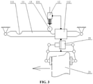
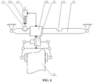
- FIG. 1 , FIG. 2 , FIG. 3 and FIG. 4 all show a state of the brake clamp 23 moving from a right end of the guide rail 11 to a left end of the guide rail 11 in the drawings.
- a sliding rail 121 extending in the vertical direction is provided on the base 12; a sliding block 122 that is moveable along an extension direction of the sliding rail 121 is provided on the sliding rail 121; and a top end of the spring 131 is connected to the sliding block 122.
- a force applied on the brake clamp 23 is transmitted to the sliding block 122 via the locking member 13, so as to drive the sliding block 122 to move appropriately along the sliding rail 121, which can effectively relieve the minor-scale swing and the structural impact of the brake clamp 23 during normal travelling, provide an effective buffering for an initial moving force of the brake clamp 23 when the vehicle performs the gauge-changing operation, prevent the force transmitted under a large-scale movement tendency of the brake clamp 23 from generating a rigid impact on the vehicle frame 22, and ensure the stability of the vehicle body and riding comfort of the rail vehicle.
- the locking member 13 is a connecting rod; two ends of the connecting rod are respectively hinged with the spring 131 and the brake clamp 23; the spring 131 is located directly above the midpoint of the guide rail 11, and a distance between the bottom end of the spring 131 in a limit compression state and the midpoint of the guide rail 11 is not less than a length of the connecting rod.
- This kind of connecting rod has a simple and reliable structure, and the distance between the bottom end of the spring 131 in the limit compression state and the midpoint of the guide rail 11 is not less than the length of the connecting rod, which can effectively prevent the brake clamp 23 from being blocked or stuck during the lateral movement, ensure the overall gauge-changing action efficiency and the assembly linkage of the brake clamp 23 and even the brake assembly, and improve the overall gauge-change action efficiency and travelling stability of the rail vehicle correspondingly.
- FIG. 3 is a schematic structural view of a brake assembly during movement provided according to another specific embodiment of the present application; and FIG. 4 is a schematic structural view of the brake assembly in FIG. 3 after an action is completed.
- the locking member 13 is a locking pin connected to the bottom portion of the spring 131, and locking holes 111 that are detachably clamped with the locking pin are respectively provided on top portions of two ends of the guide rail 11.
- a force transmission efficiency of this kind of locking pin is relatively high.
- a component linkage process is flexible and efficient, and the locking holes 111 can lock the locking pin in time and accurately after the brake clamp 23 has been moved in position, so that a position of the brake clamp 23 is locked by linkage so as to prevent the brake clamp 23 from loosening or misalignment during the normal travelling of the vehicle, and ensure the travelling stability and comfort of the vehicle.
- the locking pin is a ball pin
- the locking hole 111 is a spherical hole.
- the stress distribution between the ball pin and related contacting members is relatively reasonable, which can effectively avoid the structural damage on related matching members caused by excessive rigid impact.
- the spherical hole can effectively reduce the resistance of the ball pin in the process of disengaging and engaging the hole, and can improve the alignment efficiency between the locking pin and the locking hole 111.
- a moving block 112 that is moveable along the extension direction of the guide rail 11 is provided on the guide rail 11; the brake clamp 23 is arranged at a bottom portion of the moving block 112 in linkage.
- the moving block 112 can provide a reliable structural connection between the brake clamp 23 and the guide rail 11, avoid interference with the main structure of the brake clamp 23 due to the direct connection of the brake clamp 23 and the guide rail 11, ensure the degree of freedom of braking and clamping action of the brake clamp 23 and the working stability of the brake clamp 23, and ensure the working reliability of the brake assembly of the rail vehicle.
- the rail vehicle provided according to the present application includes a vehicle frame and a brake assembly, and the brake assembly is the brake assembly described in the above embodiments.
- the brake assembly of the rail vehicle has a wide-range lateral movement capability and can fully meet the requirement of working conditions when a rail vehicle is traveling on a gauge-changing rail.
- the brake disc drives the brake clamp to move accordingly along the extension direction of the guide rail, which achieves spacing adjustment of two corresponding brake clamps respectively arranged on two sides of the bottom of the vehicle body, so as to adapt to the adjusted rail gauge size, further ensure that relevant components of the rail vehicle can be adaptively adjusted according to the current gauge-changing operation, and ensure that the rail vehicle continues to maintain stable and continuous travelling after the gauge-changing operation is completed. Since the above brake clamp can move by a large displacement along the extension direction of the guide rail, an adjustment range of a lateral position of the brake clamp is greatly improved, and the adaptability of the gauge-changing working conditions of the rail vehicle can be improved accordingly.
- the rail vehicle using the above brake assembly provided according to the present application has a wide-range lateral movement capability and can fully meet the requirement of working conditions when a rail vehicle is traveling on a gauge-changing rail.
Landscapes
- Engineering & Computer Science (AREA)
- Mechanical Engineering (AREA)
- General Engineering & Computer Science (AREA)
- Transportation (AREA)
- Braking Arrangements (AREA)
Abstract
Description
- This disclosure claims priority of
Chinese Patent Application No. 201910703018.0, titled "RAILWAY VEHICLE AND BRAKING ASSEMBLY THEREOF", filed with the China National Intellectual Property Administration on July 31, 2019 - The present disclosure relates to the technical field of supporting assemblies for railway vehicle brake systems, and in particular to a brake assembly and a railway vehicle using the brake assembly.
- At present, a rail gauge adopted by most of the railway vehicles in China is a standard gauge, so a fixed gauge bogie is adopted. That is, a distance between two sets of wheel pairs of a vehicle remains unchanged, and there is only a small amount of lateral movement between a main frame of the vehicle and the wheel pairs. However, in some areas, a railway vehicle needs to run continuously on rails with different rail gauges, so that the bogie is required to have a gauge-changing function. That is, the distance between the two sets of wheels can be changed according to the rail gauge of the rail being travelled on.
- Correspondingly, a brake disc installed on the wheel pair may also perform a gauge-changing movement with the wheel pair, and a brake clamp unit that is matched with the brake disc must also have the gauge-changing function. However, the existing brake clamp unit is installed on the main frame of the vehicle, and cannot perform a wide-range lateral movement, and therefore cannot meet corresponding requirement of a gauge-changing operation.
- Therefore, a technical issue to be addressed presently by those skilled in the art is to make each component of the vehicle brake assembly have a wide-range lateral movement capability, so that the brake assembly can meet the requirement of the vehicle for travelling on a gauge-changing rail.
- An object of the present application is to provide a brake assembly, which has a wide-range lateral movement capability and can fully meet the requirement of working conditions when a rail vehicle is traveling on a gauge-changing rail. Another object of the present application is to provide a rail vehicle using the above brake assembly.
- In order to solve the above technical problems, a brake assembly is provided according to the present application, which includes a brake disc arranged under a vehicle frame and a guide rail located between the vehicle frame and the brake disc, where the guide rail extends along a width direction of the vehicle frame; the guide rail is provided with a brake clamp clamped on the brake disc, and the brake clamp is movable along an extension direction of the guide rail.
- Preferably, a base is provided on the vehicle frame, a locking member that cooperates with the brake clamp is provided under the base, and a spring that is extendable and retractable in a vertical direction is connected between the locking member and the base.
- Preferably, a sliding rail extending in the vertical direction is provided on the base; a sliding block that is moveable along an extension direction of the sliding rail is provided on the sliding rail; and a top end of the spring is connected to the sliding block.
- Preferably, the locking member is a connecting rod; two ends of the connecting rod are respectively hinged with the spring and the brake clamp; the spring is located directly above a midpoint of the guide rail, and a distance between a bottom end of the spring in a limit compression state and the midpoint of the guide rail is not less than a length of the connecting rod.
- Preferably, the locking member is a locking pin connected to a bottom portion of the spring, and locking holes that are detachably clamped with the locking pin are respectively provided at top portions of two ends of the guide rail.
- Preferably, the locking pin is a ball pin, and the locking hole is a spherical hole.
- Preferably, a moving block that is moveable along the extension direction of the guide rail is provided on the guide rail; and the brake clamp is arranged at a bottom portion of the moving block in linkage.
- A rail vehicle is further provided according to the present application, which includes a vehicle frame and a brake assembly, where the brake assembly is the brake assembly according to any one of the above.
- Compared with the above background technology, in the brake assembly provided according to the present application, during a travelling process of the rail vehicle, when the vehicle performs a gauge-changing operation, the brake disc drives the brake clamp to move accordingly along the extension direction of the guide rail, which achieves spacing adjustment of two corresponding brake clamps respectively arranged on two sides of the bottom of a vehicle body, so as to adapt to the adjusted rail gauge size, further ensure that relevant components of the rail vehicle can be adaptively adjusted according to the current gauge-changing operation, and ensure that the rail vehicle continues to maintain stable and continuous travelling after the gauge-changing operation is completed. Since the above brake clamp can move by a large displacement along the extension direction of the guide rail, an adjustment range of a lateral position of the brake clamp is greatly improved, and the adaptability of the gauge-changing working conditions of the rail vehicle can be improved accordingly.
- In another preferred solution of the present application, the base is provided on the vehicle frame, and the locking member that cooperates with the brake clamp is provided under the base. A spring that is extendable and retractable in the vertical direction is connected between the locking member and the base. In a normal travelling state of the vehicle, the locking member cooperates with the spring and the base to form a connecting rod locking mechanism, which prevents the brake clamp from generating a tendency to move along the extension direction of the guide rail, and ensures the structural integrity of the brake assembly and the travelling stability of the vehicle. When the gauge-changing operation is performed, the brake clamp is subjected to a relatively large lateral force transmitted from the brake disc, which prompts the brake clamp to overcome an elastic resistance of the spring and move from one end of the guide rail to the other of the guide rail. During this movement, the brake clamp drives the locking member to move in linkage, and further compresses the spring until it reaches the limit position. After that, the brake clamp continues to move and gradually approaches the other end of the guide rail. At this time, the brake clamp does not apply force on the spring, so that the spring begins to gradually extend and apply an elastic restoring force of the spring on the brake clamp so as to promote the brake clamp to approach the other end of the guide rail more quickly until the spring is fully extended and restored to a free state. In a case that the rail gauge is changed again and the brake clamp has a tendency to move to the original end of the guide rail again, each mechanism can repeat the above action process in reverse. The locking member, the spring, and the base cooperate to provide a certain degree of initial portion limiting and final portion assistance for the brake clamp when the gauge-changing operation is required, so as to further improve the action efficiency of the brake assembly and the linkage of related components of the rail vehicle during the gauge-changing operation, and ensure the travelling comfort and stability of the vehicle.
- For more clearly illustrating embodiments of the present disclosure or the technical solutions in the conventional technology, drawings referred to for describing the embodiments or the conventional technology will be briefly described hereinafter. Apparently, drawings in the following description are only examples of the present disclosure, and for the person skilled in the art, other drawings may be obtained based on the provided drawings without any creative efforts.
-
FIG. 1 is a schematic structural view of a brake assembly during movement provided according to a specific embodiment of the present application; -
FIG. 2 is a schematic structural view of the brake assembly inFIG. 1 after an action is completed; -
FIG. 3 is a schematic structural view of a brake assembly during movement provided according to another specific embodiment of the present application; and -
FIG. 4 is a schematic structural view of the brake assembly inFIG. 3 after an action is completed. - 11-guide rail, 111-locking hole, 112-moving block, 12-base, 121-sliding rail, 122-sliding block, 13-locking member, 131-spring, 21-brake disc, 22-vehicle frame, 23-brake clamp.
- A core of the present application is to provide a brake assembly, which has a wide-range lateral movement capability and can fully meet the requirement of working conditions when a rail vehicle is traveling on a gauge-changing rail; moreover, a rail vehicle using the above brake assembly is further provided.
- In order to enable those skilled in the art to better understand the solution of the present application, the present application will be further described in detail below with reference to the accompanying drawings and specific embodiments.
- Reference is made to
FIG. 1 andFIG. 2 .FIG. 1 is a schematic structural view of a brake assembly during movement provided according to a specific embodiment of the present application;FIG. 2 is a schematic structural view of the brake assembly inFIG. 1 after an action is completed. - In a specific embodiment, the brake assembly provided according to the present application includes a
brake disc 21 arranged under avehicle frame 22 and aguide rail 11 located between thevehicle frame 22 and thebrake disc 21, where theguide rail 11 extends along the width direction of thevehicle frame 22; theguide rail 11 is provided with abrake clamp 23 clamped on thebrake disc 21, and thebrake clamp 23 is movable along the extension direction of theguide rail 11. - During a travelling process of the rail vehicle, when the vehicle performs a gauge-changing operation, the
brake disc 21 drives thebrake clamp 23 to move accordingly along the extension direction of theguide rail 11, which achieves spacing adjustment of twocorresponding brake clamps 23 respectively arranged on two sides of the bottom of a vehicle body, so as to adapt to the adjusted rail gauge size, further ensure that relevant components of the rail vehicle can be adaptively adjusted according to the current gauge-changing operation, and ensure that the rail vehicle continues to maintain stable and continuous travelling after the gauge-changing operation is completed. Since theabove brake clamp 23 can move by a large displacement along the extension direction of theguide rail 11, an adjustment range of a lateral position of thebrake clamp 23 is greatly improved, and the adaptability of the gauge-changing working conditions of the rail vehicle can be improved accordingly. - It should be noted that the "lateral" mentioned above and hereinafter, unless otherwise specified, refers to the width direction of the
vehicle frame 22, that is, the extension direction of theguide rail 11, which will not be repeated hereinafter. - Specifically, a
base 12 is provided on thevehicle frame 22, and alocking member 13 that cooperates with thebrake clamp 23 is provided under thebase 12. Aspring 131 that is extendable and retractable in a vertical direction is connected between thelocking member 13 and thebase 12. In a normal travelling state of the vehicle, thelocking member 13 cooperates with thespring 131 and thebase 12 to form a connecting rod locking mechanism, which prevents thebrake clamp 23 from generating a tendency to move along the extension direction of theguide rail 11, and ensures the structural integrity of the brake assembly and the travelling stability of the vehicle. When the gauge-changing operation is performed, thebrake clamp 23 is subjected to a relatively large lateral force transmitted from thebrake disc 21, which prompts thebrake clamp 23 to overcome an elastic resistance of thespring 131 and move from one end of theguide rail 11 to the other of theguide rail 11. During this movement, thebrake clamp 23 drives thelocking member 13 to move in linkage, and further compresses thespring 131 until it reaches the limit position. After that, thebrake clamp 23 continues to move and gradually approaches the other end of theguide rail 11. At this time, thebrake clamp 23 does not apply force on thespring 131, so that thespring 131 begins to gradually extend and apply an elastic restoring force of thespring 131 on thebrake clamp 23 so as to promote thebrake clamp 23 to approach the other end of theguide rail 11 more quickly until thespring 131 is fully extended and restored to a free state. In a case that the rail gauge is changed again and thebrake clamp 23 has a tendency to move to the original end of theguide rail 11 again, each mechanism can repeat the above action process in reverse. Thelocking member 13, thespring 131, and thebase 12 cooperate to provide a certain degree of initial portion limiting and final portion assistance for thebrake clamp 23 when the gauge-changing operation is required, so as to further improve the action efficiency of the brake assembly and the linkage of related components of the rail vehicle during the gauge-changing operation, and ensure the travelling comfort and stability of the vehicle. - It should be further explained that, in order to facilitate the reference, comparison and understanding of the technical solution, in the accompanying drawings herein,
FIG. 1 ,FIG. 2 ,FIG. 3 andFIG. 4 all show a state of thebrake clamp 23 moving from a right end of theguide rail 11 to a left end of theguide rail 11 in the drawings. - Reference is emphatically made to
FIG. 1 andFIG. 2 . A slidingrail 121 extending in the vertical direction is provided on thebase 12; asliding block 122 that is moveable along an extension direction of the slidingrail 121 is provided on the slidingrail 121; and a top end of thespring 131 is connected to thesliding block 122. In a case that thebrake clamp 23 has a tendency to move laterally, a force applied on thebrake clamp 23 is transmitted to the slidingblock 122 via thelocking member 13, so as to drive the slidingblock 122 to move appropriately along the slidingrail 121, which can effectively relieve the minor-scale swing and the structural impact of thebrake clamp 23 during normal travelling, provide an effective buffering for an initial moving force of thebrake clamp 23 when the vehicle performs the gauge-changing operation, prevent the force transmitted under a large-scale movement tendency of thebrake clamp 23 from generating a rigid impact on thevehicle frame 22, and ensure the stability of the vehicle body and riding comfort of the rail vehicle. - More specifically, the
locking member 13 is a connecting rod; two ends of the connecting rod are respectively hinged with thespring 131 and thebrake clamp 23; thespring 131 is located directly above the midpoint of theguide rail 11, and a distance between the bottom end of thespring 131 in a limit compression state and the midpoint of theguide rail 11 is not less than a length of the connecting rod. This kind of connecting rod has a simple and reliable structure, and the distance between the bottom end of thespring 131 in the limit compression state and the midpoint of theguide rail 11 is not less than the length of the connecting rod, which can effectively prevent thebrake clamp 23 from being blocked or stuck during the lateral movement, ensure the overall gauge-changing action efficiency and the assembly linkage of thebrake clamp 23 and even the brake assembly, and improve the overall gauge-change action efficiency and travelling stability of the rail vehicle correspondingly. - Reference is emphatically made to
FIG. 3 andFIG. 4 .FIG. 3 is a schematic structural view of a brake assembly during movement provided according to another specific embodiment of the present application; andFIG. 4 is a schematic structural view of the brake assembly inFIG. 3 after an action is completed. - In this specific embodiment of the present solution, the locking
member 13 is a locking pin connected to the bottom portion of thespring 131, and lockingholes 111 that are detachably clamped with the locking pin are respectively provided on top portions of two ends of theguide rail 11. A force transmission efficiency of this kind of locking pin is relatively high. A component linkage process is flexible and efficient, and the locking holes 111 can lock the locking pin in time and accurately after thebrake clamp 23 has been moved in position, so that a position of thebrake clamp 23 is locked by linkage so as to prevent thebrake clamp 23 from loosening or misalignment during the normal travelling of the vehicle, and ensure the travelling stability and comfort of the vehicle. - In addition, the locking pin is a ball pin, and the
locking hole 111 is a spherical hole. The stress distribution between the ball pin and related contacting members is relatively reasonable, which can effectively avoid the structural damage on related matching members caused by excessive rigid impact. Moreover, the spherical hole can effectively reduce the resistance of the ball pin in the process of disengaging and engaging the hole, and can improve the alignment efficiency between the locking pin and thelocking hole 111. - On the other hand, a moving
block 112 that is moveable along the extension direction of theguide rail 11 is provided on theguide rail 11; thebrake clamp 23 is arranged at a bottom portion of the movingblock 112 in linkage. The movingblock 112 can provide a reliable structural connection between thebrake clamp 23 and theguide rail 11, avoid interference with the main structure of thebrake clamp 23 due to the direct connection of thebrake clamp 23 and theguide rail 11, ensure the degree of freedom of braking and clamping action of thebrake clamp 23 and the working stability of thebrake clamp 23, and ensure the working reliability of the brake assembly of the rail vehicle. - In a specific embodiment, the rail vehicle provided according to the present application includes a vehicle frame and a brake assembly, and the brake assembly is the brake assembly described in the above embodiments. The brake assembly of the rail vehicle has a wide-range lateral movement capability and can fully meet the requirement of working conditions when a rail vehicle is traveling on a gauge-changing rail.
- In summary, in the brake assembly provided according to the present application, during a travelling process of the rail vehicle, when the vehicle performs a gauge-changing operation, the brake disc drives the brake clamp to move accordingly along the extension direction of the guide rail, which achieves spacing adjustment of two corresponding brake clamps respectively arranged on two sides of the bottom of the vehicle body, so as to adapt to the adjusted rail gauge size, further ensure that relevant components of the rail vehicle can be adaptively adjusted according to the current gauge-changing operation, and ensure that the rail vehicle continues to maintain stable and continuous travelling after the gauge-changing operation is completed. Since the above brake clamp can move by a large displacement along the extension direction of the guide rail, an adjustment range of a lateral position of the brake clamp is greatly improved, and the adaptability of the gauge-changing working conditions of the rail vehicle can be improved accordingly.
- In addition, the rail vehicle using the above brake assembly provided according to the present application has a wide-range lateral movement capability and can fully meet the requirement of working conditions when a rail vehicle is traveling on a gauge-changing rail.
- The brake assembly and the rail vehicle using the brake assembly provided according to the present application have been described in detail above. Specific examples are used herein to illustrate the principle and implementation of the present application. The description of the above embodiments is only used to help understand the method and core idea of the present application. It should be pointed out that for those of ordinary skill in the art, without departing from the principle of the present application, several improvements and modifications may be made to the present application, and these improvements and modifications also fall within the scope of protection of the claims of the present application.
Claims (8)
- A brake assembly, comprising a brake disc provided under a vehicle frame and a guide rail located between the vehicle frame and the brake disc, wherein the guide rail extends along a width direction of the vehicle frame; the guide rail is provided with a brake clamp clamped on the brake disc, and the brake clamp is movable along an extension direction of the guide rail.
- The brake assembly according to claim 1, wherein a base is provided on the vehicle frame, and a locking member that cooperates with the brake clamp is arranged under the base; and a spring that is extendable and retractable in a vertical direction is connected between the locking member and the base.
- The brake assembly according to claim 2, wherein a sliding rail extending in the vertical direction is provided on the base; a sliding block that is moveable along an extension direction of the sliding rail is provided on the sliding rail; and a top end of the spring is connected to the sliding block.
- The brake assembly according to claim 2, wherein the locking member is a connecting rod; two ends of the connecting rod are respectively hinged with the spring and the brake clamp; wherein the spring is located directly above a midpoint of the guide rail, and a distance between a bottom end of the spring in a limit compression state and the midpoint of the guide rail is not less than a length of the connecting rod.
- The brake assembly according to claim 2, wherein the locking member is a locking pin connected to a bottom portion of the spring, and locking holes that are detachably clamped on the locking pin are respectively provided on top portions of two ends of the guide rail.
- The brake assembly according to claim 5, wherein the locking pin is a ball pin, and each of the locking holes is a spherical hole.
- The brake assembly according to claim 1, wherein a moving block that is moveable along the extension direction of the guide rail is provided on the guide rail; and the brake clamp is arranged at a bottom portion of the moving block in linkage.
- A rail vehicle comprising a vehicle frame and a brake assembly, wherein the brake assembly is the brake assembly according to any one of claims 1 to 7.
Priority Applications (1)
| Application Number | Priority Date | Filing Date | Title |
|---|---|---|---|
| RS20240173A RS65151B1 (en) | 2019-07-31 | 2020-06-11 | Railway vehicle and braking assembly thereof |
Applications Claiming Priority (2)
| Application Number | Priority Date | Filing Date | Title |
|---|---|---|---|
| CN201910703018.0A CN110371157B (en) | 2019-07-31 | 2019-07-31 | Rail vehicle and brake assembly thereof |
| PCT/CN2020/095567 WO2021017657A1 (en) | 2019-07-31 | 2020-06-11 | Railway vehicle and braking assembly thereof |
Publications (3)
| Publication Number | Publication Date |
|---|---|
| EP3957540A1 true EP3957540A1 (en) | 2022-02-23 |
| EP3957540A4 EP3957540A4 (en) | 2022-08-24 |
| EP3957540B1 EP3957540B1 (en) | 2023-12-13 |
Family
ID=68257514
Family Applications (1)
| Application Number | Title | Priority Date | Filing Date |
|---|---|---|---|
| EP20847806.5A Active EP3957540B1 (en) | 2019-07-31 | 2020-06-11 | Railway vehicle and braking assembly thereof |
Country Status (7)
| Country | Link |
|---|---|
| EP (1) | EP3957540B1 (en) |
| CN (1) | CN110371157B (en) |
| HU (1) | HUE064858T2 (en) |
| MY (1) | MY209433A (en) |
| RS (1) | RS65151B1 (en) |
| SG (1) | SG11202112343XA (en) |
| WO (1) | WO2021017657A1 (en) |
Families Citing this family (1)
| Publication number | Priority date | Publication date | Assignee | Title |
|---|---|---|---|---|
| CN110371157B (en) * | 2019-07-31 | 2020-12-25 | 中车长春轨道客车股份有限公司 | Rail vehicle and brake assembly thereof |
Family Cites Families (10)
| Publication number | Priority date | Publication date | Assignee | Title |
|---|---|---|---|---|
| US3118258A (en) * | 1961-03-03 | 1964-01-21 | Machine machine | |
| JP4182553B2 (en) * | 1997-11-10 | 2008-11-19 | 株式会社竹屋 | Displacement control device for launch operation part of pachinko machine |
| JP2003205840A (en) * | 2002-01-16 | 2003-07-22 | Fuji Heavy Ind Ltd | Rail-to-rail variable bogie excavator |
| CN106915361B (en) * | 2017-03-21 | 2019-04-12 | 中车山东机车车辆有限公司 | A kind of dress gauge-changeable bogie of adjustable unit brake apparatus |
| CN107628059B (en) * | 2017-09-01 | 2023-05-26 | 中车唐山机车车辆有限公司 | Braking device applied to variable-track-gauge bogie |
| CN108482415B (en) * | 2018-03-12 | 2020-02-14 | 中车青岛四方车辆研究所有限公司 | Rigid follow-up mechanism for variable gauge bogie and brake clamp unit |
| CN108423027B (en) * | 2018-03-16 | 2019-07-12 | 中车青岛四方车辆研究所有限公司 | Follow-up mechanism for variable-gauge bogie and brake clamp unit |
| CN108609028B (en) * | 2018-04-13 | 2020-05-12 | 中车青岛四方机车车辆股份有限公司 | A kind of railway vehicle with variable gauge bogie |
| CN109501831B (en) * | 2018-12-07 | 2024-04-26 | 中国铁道科学研究院集团有限公司 | Brake caliper track change device |
| CN110371157B (en) * | 2019-07-31 | 2020-12-25 | 中车长春轨道客车股份有限公司 | Rail vehicle and brake assembly thereof |
-
2019
- 2019-07-31 CN CN201910703018.0A patent/CN110371157B/en active Active
-
2020
- 2020-06-11 RS RS20240173A patent/RS65151B1/en unknown
- 2020-06-11 HU HUE20847806A patent/HUE064858T2/en unknown
- 2020-06-11 WO PCT/CN2020/095567 patent/WO2021017657A1/en not_active Ceased
- 2020-06-11 EP EP20847806.5A patent/EP3957540B1/en active Active
- 2020-06-11 MY MYPI2021006699A patent/MY209433A/en unknown
- 2020-06-11 SG SG11202112343XA patent/SG11202112343XA/en unknown
Also Published As
| Publication number | Publication date |
|---|---|
| CN110371157A (en) | 2019-10-25 |
| WO2021017657A1 (en) | 2021-02-04 |
| EP3957540B1 (en) | 2023-12-13 |
| HUE064858T2 (en) | 2024-04-28 |
| CN110371157B (en) | 2020-12-25 |
| EP3957540A4 (en) | 2022-08-24 |
| SG11202112343XA (en) | 2021-12-30 |
| MY209433A (en) | 2025-07-09 |
| RS65151B1 (en) | 2024-02-29 |
Similar Documents
| Publication | Publication Date | Title |
|---|---|---|
| CN102431607B (en) | Lifting clamping device for car door conveying line | |
| CN108146403B (en) | Straddle type monorail bogie assembly overhauling and replacing equipment | |
| RU2729854C1 (en) | Follow-up mechanism and brake support unit for bogie with variable track width | |
| CN104781129A (en) | Coupler torsion spring centering device | |
| CN109050540A (en) | A kind of crusing robot swing Self-resetting mechanism | |
| EP3957540B1 (en) | Railway vehicle and braking assembly thereof | |
| CN209259508U (en) | A kind of teeth belt type transmission rail clamping device | |
| CN216105647U (en) | Anti-derailing device for navigation vehicle | |
| CN220924122U (en) | Multi-stage buffer track train stopper | |
| CN105984359A (en) | Guide wheel guide control device and rubber tire guide rail streetcar | |
| CN120135939A (en) | Heavy duty sliding turnout for monorail crane track | |
| GB2051189A (en) | Railway points | |
| CN110525527B (en) | A triangular track wheel and gear tooth guide and limiting device | |
| CN110342373B (en) | Logistics track double-swing-rod linkage type car arrester | |
| CN218140906U (en) | Connecting mechanism convenient for quick combination for vehicle | |
| CN219313799U (en) | Multi-track switching device for overhead suspension trolley conveying line | |
| US5052306A (en) | Mobile track position correcting and tamping machine | |
| CN116706617A (en) | Electric connector with connection locking structure | |
| CN210316723U (en) | Clamping rod device for carrier of stereo garage and carrier | |
| CN220842539U (en) | Flexible hard-connection pull rod device | |
| CN201494927U (en) | Slidable stopper | |
| CN221366588U (en) | A magnetic levitation vehicle and a box connection device thereof | |
| CN116252628B (en) | Current receiving device | |
| CN223355608U (en) | Anti-collision fixed train stopper | |
| WO2022174896A1 (en) | Positioning unit and contacting method |
Legal Events
| Date | Code | Title | Description |
|---|---|---|---|
| STAA | Information on the status of an ep patent application or granted ep patent |
Free format text: STATUS: THE INTERNATIONAL PUBLICATION HAS BEEN MADE |
|
| PUAI | Public reference made under article 153(3) epc to a published international application that has entered the european phase |
Free format text: ORIGINAL CODE: 0009012 |
|
| STAA | Information on the status of an ep patent application or granted ep patent |
Free format text: STATUS: REQUEST FOR EXAMINATION WAS MADE |
|
| 17P | Request for examination filed |
Effective date: 20211119 |
|
| AK | Designated contracting states |
Kind code of ref document: A1 Designated state(s): AL AT BE BG CH CY CZ DE DK EE ES FI FR GB GR HR HU IE IS IT LI LT LU LV MC MK MT NL NO PL PT RO RS SE SI SK SM TR |
|
| A4 | Supplementary search report drawn up and despatched |
Effective date: 20220727 |
|
| RIC1 | Information provided on ipc code assigned before grant |
Ipc: B61H 5/00 20060101AFI20220722BHEP |
|
| DAV | Request for validation of the european patent (deleted) | ||
| DAX | Request for extension of the european patent (deleted) | ||
| GRAP | Despatch of communication of intention to grant a patent |
Free format text: ORIGINAL CODE: EPIDOSNIGR1 |
|
| STAA | Information on the status of an ep patent application or granted ep patent |
Free format text: STATUS: GRANT OF PATENT IS INTENDED |
|
| INTG | Intention to grant announced |
Effective date: 20230705 |
|
| GRAS | Grant fee paid |
Free format text: ORIGINAL CODE: EPIDOSNIGR3 |
|
| GRAA | (expected) grant |
Free format text: ORIGINAL CODE: 0009210 |
|
| STAA | Information on the status of an ep patent application or granted ep patent |
Free format text: STATUS: THE PATENT HAS BEEN GRANTED |
|
| AK | Designated contracting states |
Kind code of ref document: B1 Designated state(s): AL AT BE BG CH CY CZ DE DK EE ES FI FR GB GR HR HU IE IS IT LI LT LU LV MC MK MT NL NO PL PT RO RS SE SI SK SM TR |
|
| REG | Reference to a national code |
Ref country code: GB Ref legal event code: FG4D |
|
| REG | Reference to a national code |
Ref country code: CH Ref legal event code: EP |
|
| REG | Reference to a national code |
Ref country code: DE Ref legal event code: R096 Ref document number: 602020022859 Country of ref document: DE |
|
| REG | Reference to a national code |
Ref country code: IE Ref legal event code: FG4D |
|
| PG25 | Lapsed in a contracting state [announced via postgrant information from national office to epo] |
Ref country code: GR Free format text: LAPSE BECAUSE OF FAILURE TO SUBMIT A TRANSLATION OF THE DESCRIPTION OR TO PAY THE FEE WITHIN THE PRESCRIBED TIME-LIMIT Effective date: 20240314 |
|
| REG | Reference to a national code |
Ref country code: LT Ref legal event code: MG9D |
|
| PG25 | Lapsed in a contracting state [announced via postgrant information from national office to epo] |
Ref country code: LT Free format text: LAPSE BECAUSE OF FAILURE TO SUBMIT A TRANSLATION OF THE DESCRIPTION OR TO PAY THE FEE WITHIN THE PRESCRIBED TIME-LIMIT Effective date: 20231213 |
|
| REG | Reference to a national code |
Ref country code: NL Ref legal event code: MP Effective date: 20231213 |
|
| PG25 | Lapsed in a contracting state [announced via postgrant information from national office to epo] |
Ref country code: ES Free format text: LAPSE BECAUSE OF FAILURE TO SUBMIT A TRANSLATION OF THE DESCRIPTION OR TO PAY THE FEE WITHIN THE PRESCRIBED TIME-LIMIT Effective date: 20231213 |
|
| REG | Reference to a national code |
Ref country code: HU Ref legal event code: AG4A Ref document number: E064858 Country of ref document: HU |
|
| PG25 | Lapsed in a contracting state [announced via postgrant information from national office to epo] |
Ref country code: LT Free format text: LAPSE BECAUSE OF FAILURE TO SUBMIT A TRANSLATION OF THE DESCRIPTION OR TO PAY THE FEE WITHIN THE PRESCRIBED TIME-LIMIT Effective date: 20231213 Ref country code: GR Free format text: LAPSE BECAUSE OF FAILURE TO SUBMIT A TRANSLATION OF THE DESCRIPTION OR TO PAY THE FEE WITHIN THE PRESCRIBED TIME-LIMIT Effective date: 20240314 Ref country code: ES Free format text: LAPSE BECAUSE OF FAILURE TO SUBMIT A TRANSLATION OF THE DESCRIPTION OR TO PAY THE FEE WITHIN THE PRESCRIBED TIME-LIMIT Effective date: 20231213 Ref country code: BG Free format text: LAPSE BECAUSE OF FAILURE TO SUBMIT A TRANSLATION OF THE DESCRIPTION OR TO PAY THE FEE WITHIN THE PRESCRIBED TIME-LIMIT Effective date: 20240313 |
|
| REG | Reference to a national code |
Ref country code: AT Ref legal event code: MK05 Ref document number: 1640235 Country of ref document: AT Kind code of ref document: T Effective date: 20231213 |
|
| PG25 | Lapsed in a contracting state [announced via postgrant information from national office to epo] |
Ref country code: NL Free format text: LAPSE BECAUSE OF FAILURE TO SUBMIT A TRANSLATION OF THE DESCRIPTION OR TO PAY THE FEE WITHIN THE PRESCRIBED TIME-LIMIT Effective date: 20231213 |
|
| PG25 | Lapsed in a contracting state [announced via postgrant information from national office to epo] |
Ref country code: SE Free format text: LAPSE BECAUSE OF FAILURE TO SUBMIT A TRANSLATION OF THE DESCRIPTION OR TO PAY THE FEE WITHIN THE PRESCRIBED TIME-LIMIT Effective date: 20231213 Ref country code: NO Free format text: LAPSE BECAUSE OF FAILURE TO SUBMIT A TRANSLATION OF THE DESCRIPTION OR TO PAY THE FEE WITHIN THE PRESCRIBED TIME-LIMIT Effective date: 20240313 Ref country code: NL Free format text: LAPSE BECAUSE OF FAILURE TO SUBMIT A TRANSLATION OF THE DESCRIPTION OR TO PAY THE FEE WITHIN THE PRESCRIBED TIME-LIMIT Effective date: 20231213 Ref country code: LV Free format text: LAPSE BECAUSE OF FAILURE TO SUBMIT A TRANSLATION OF THE DESCRIPTION OR TO PAY THE FEE WITHIN THE PRESCRIBED TIME-LIMIT Effective date: 20231213 Ref country code: HR Free format text: LAPSE BECAUSE OF FAILURE TO SUBMIT A TRANSLATION OF THE DESCRIPTION OR TO PAY THE FEE WITHIN THE PRESCRIBED TIME-LIMIT Effective date: 20231213 |
|
| PG25 | Lapsed in a contracting state [announced via postgrant information from national office to epo] |
Ref country code: IS Free format text: LAPSE BECAUSE OF FAILURE TO SUBMIT A TRANSLATION OF THE DESCRIPTION OR TO PAY THE FEE WITHIN THE PRESCRIBED TIME-LIMIT Effective date: 20240413 |
|
| PG25 | Lapsed in a contracting state [announced via postgrant information from national office to epo] |
Ref country code: CZ Free format text: LAPSE BECAUSE OF FAILURE TO SUBMIT A TRANSLATION OF THE DESCRIPTION OR TO PAY THE FEE WITHIN THE PRESCRIBED TIME-LIMIT Effective date: 20231213 Ref country code: AT Free format text: LAPSE BECAUSE OF FAILURE TO SUBMIT A TRANSLATION OF THE DESCRIPTION OR TO PAY THE FEE WITHIN THE PRESCRIBED TIME-LIMIT Effective date: 20231213 |
|
| PG25 | Lapsed in a contracting state [announced via postgrant information from national office to epo] |
Ref country code: SK Free format text: LAPSE BECAUSE OF FAILURE TO SUBMIT A TRANSLATION OF THE DESCRIPTION OR TO PAY THE FEE WITHIN THE PRESCRIBED TIME-LIMIT Effective date: 20231213 |
|
| PG25 | Lapsed in a contracting state [announced via postgrant information from national office to epo] |
Ref country code: SM Free format text: LAPSE BECAUSE OF FAILURE TO SUBMIT A TRANSLATION OF THE DESCRIPTION OR TO PAY THE FEE WITHIN THE PRESCRIBED TIME-LIMIT Effective date: 20231213 Ref country code: SK Free format text: LAPSE BECAUSE OF FAILURE TO SUBMIT A TRANSLATION OF THE DESCRIPTION OR TO PAY THE FEE WITHIN THE PRESCRIBED TIME-LIMIT Effective date: 20231213 Ref country code: RO Free format text: LAPSE BECAUSE OF FAILURE TO SUBMIT A TRANSLATION OF THE DESCRIPTION OR TO PAY THE FEE WITHIN THE PRESCRIBED TIME-LIMIT Effective date: 20231213 Ref country code: IT Free format text: LAPSE BECAUSE OF FAILURE TO SUBMIT A TRANSLATION OF THE DESCRIPTION OR TO PAY THE FEE WITHIN THE PRESCRIBED TIME-LIMIT Effective date: 20231213 Ref country code: IS Free format text: LAPSE BECAUSE OF FAILURE TO SUBMIT A TRANSLATION OF THE DESCRIPTION OR TO PAY THE FEE WITHIN THE PRESCRIBED TIME-LIMIT Effective date: 20240413 Ref country code: EE Free format text: LAPSE BECAUSE OF FAILURE TO SUBMIT A TRANSLATION OF THE DESCRIPTION OR TO PAY THE FEE WITHIN THE PRESCRIBED TIME-LIMIT Effective date: 20231213 Ref country code: CZ Free format text: LAPSE BECAUSE OF FAILURE TO SUBMIT A TRANSLATION OF THE DESCRIPTION OR TO PAY THE FEE WITHIN THE PRESCRIBED TIME-LIMIT Effective date: 20231213 Ref country code: AT Free format text: LAPSE BECAUSE OF FAILURE TO SUBMIT A TRANSLATION OF THE DESCRIPTION OR TO PAY THE FEE WITHIN THE PRESCRIBED TIME-LIMIT Effective date: 20231213 |
|
| PG25 | Lapsed in a contracting state [announced via postgrant information from national office to epo] |
Ref country code: PL Free format text: LAPSE BECAUSE OF FAILURE TO SUBMIT A TRANSLATION OF THE DESCRIPTION OR TO PAY THE FEE WITHIN THE PRESCRIBED TIME-LIMIT Effective date: 20231213 Ref country code: PT Free format text: LAPSE BECAUSE OF FAILURE TO SUBMIT A TRANSLATION OF THE DESCRIPTION OR TO PAY THE FEE WITHIN THE PRESCRIBED TIME-LIMIT Effective date: 20240415 |
|
| PG25 | Lapsed in a contracting state [announced via postgrant information from national office to epo] |
Ref country code: PT Free format text: LAPSE BECAUSE OF FAILURE TO SUBMIT A TRANSLATION OF THE DESCRIPTION OR TO PAY THE FEE WITHIN THE PRESCRIBED TIME-LIMIT Effective date: 20240415 Ref country code: PL Free format text: LAPSE BECAUSE OF FAILURE TO SUBMIT A TRANSLATION OF THE DESCRIPTION OR TO PAY THE FEE WITHIN THE PRESCRIBED TIME-LIMIT Effective date: 20231213 |
|
| REG | Reference to a national code |
Ref country code: DE Ref legal event code: R097 Ref document number: 602020022859 Country of ref document: DE |
|
| PG25 | Lapsed in a contracting state [announced via postgrant information from national office to epo] |
Ref country code: DK Free format text: LAPSE BECAUSE OF FAILURE TO SUBMIT A TRANSLATION OF THE DESCRIPTION OR TO PAY THE FEE WITHIN THE PRESCRIBED TIME-LIMIT Effective date: 20231213 |
|
| PLBE | No opposition filed within time limit |
Free format text: ORIGINAL CODE: 0009261 |
|
| STAA | Information on the status of an ep patent application or granted ep patent |
Free format text: STATUS: NO OPPOSITION FILED WITHIN TIME LIMIT |
|
| PG25 | Lapsed in a contracting state [announced via postgrant information from national office to epo] |
Ref country code: SI Free format text: LAPSE BECAUSE OF FAILURE TO SUBMIT A TRANSLATION OF THE DESCRIPTION OR TO PAY THE FEE WITHIN THE PRESCRIBED TIME-LIMIT Effective date: 20231213 |
|
| PG25 | Lapsed in a contracting state [announced via postgrant information from national office to epo] |
Ref country code: SI Free format text: LAPSE BECAUSE OF FAILURE TO SUBMIT A TRANSLATION OF THE DESCRIPTION OR TO PAY THE FEE WITHIN THE PRESCRIBED TIME-LIMIT Effective date: 20231213 Ref country code: DK Free format text: LAPSE BECAUSE OF FAILURE TO SUBMIT A TRANSLATION OF THE DESCRIPTION OR TO PAY THE FEE WITHIN THE PRESCRIBED TIME-LIMIT Effective date: 20231213 |
|
| 26N | No opposition filed |
Effective date: 20240916 |
|
| PG25 | Lapsed in a contracting state [announced via postgrant information from national office to epo] |
Ref country code: MC Free format text: LAPSE BECAUSE OF FAILURE TO SUBMIT A TRANSLATION OF THE DESCRIPTION OR TO PAY THE FEE WITHIN THE PRESCRIBED TIME-LIMIT Effective date: 20231213 |
|
| REG | Reference to a national code |
Ref country code: CH Ref legal event code: PL |
|
| PG25 | Lapsed in a contracting state [announced via postgrant information from national office to epo] |
Ref country code: LU Free format text: LAPSE BECAUSE OF NON-PAYMENT OF DUE FEES Effective date: 20240611 |
|
| GBPC | Gb: european patent ceased through non-payment of renewal fee |
Effective date: 20240611 |
|
| PG25 | Lapsed in a contracting state [announced via postgrant information from national office to epo] |
Ref country code: IE Free format text: LAPSE BECAUSE OF NON-PAYMENT OF DUE FEES Effective date: 20240611 |
|
| PG25 | Lapsed in a contracting state [announced via postgrant information from national office to epo] |
Ref country code: BE Free format text: LAPSE BECAUSE OF NON-PAYMENT OF DUE FEES Effective date: 20240630 Ref country code: CH Free format text: LAPSE BECAUSE OF NON-PAYMENT OF DUE FEES Effective date: 20240630 |
|
| PG25 | Lapsed in a contracting state [announced via postgrant information from national office to epo] |
Ref country code: FR Free format text: LAPSE BECAUSE OF NON-PAYMENT OF DUE FEES Effective date: 20240630 |
|
| PG25 | Lapsed in a contracting state [announced via postgrant information from national office to epo] |
Ref country code: GB Free format text: LAPSE BECAUSE OF NON-PAYMENT OF DUE FEES Effective date: 20240611 |
|
| REG | Reference to a national code |
Ref country code: BE Ref legal event code: MM Effective date: 20240630 |
|
| PGFP | Annual fee paid to national office [announced via postgrant information from national office to epo] |
Ref country code: RS Payment date: 20250604 Year of fee payment: 6 |
|
| PGFP | Annual fee paid to national office [announced via postgrant information from national office to epo] |
Ref country code: HU Payment date: 20250606 Year of fee payment: 6 |
|
| PG25 | Lapsed in a contracting state [announced via postgrant information from national office to epo] |
Ref country code: FI Free format text: LAPSE BECAUSE OF FAILURE TO SUBMIT A TRANSLATION OF THE DESCRIPTION OR TO PAY THE FEE WITHIN THE PRESCRIBED TIME-LIMIT Effective date: 20231213 |
|
| PGFP | Annual fee paid to national office [announced via postgrant information from national office to epo] |
Ref country code: DE Payment date: 20250711 Year of fee payment: 6 |
|
| PG25 | Lapsed in a contracting state [announced via postgrant information from national office to epo] |
Ref country code: CY Free format text: LAPSE BECAUSE OF FAILURE TO SUBMIT A TRANSLATION OF THE DESCRIPTION OR TO PAY THE FEE WITHIN THE PRESCRIBED TIME-LIMIT; INVALID AB INITIO Effective date: 20200611 |