EP3957336A1 - Peroxide-generating air purification element - Google Patents
Peroxide-generating air purification element Download PDFInfo
- Publication number
- EP3957336A1 EP3957336A1 EP21191518.6A EP21191518A EP3957336A1 EP 3957336 A1 EP3957336 A1 EP 3957336A1 EP 21191518 A EP21191518 A EP 21191518A EP 3957336 A1 EP3957336 A1 EP 3957336A1
- Authority
- EP
- European Patent Office
- Prior art keywords
- peroxide
- air
- air purification
- purification element
- electrode
- Prior art date
- Legal status (The legal status is an assumption and is not a legal conclusion. Google has not performed a legal analysis and makes no representation as to the accuracy of the status listed.)
- Granted
Links
Images




Classifications
-
- B—PERFORMING OPERATIONS; TRANSPORTING
- B01—PHYSICAL OR CHEMICAL PROCESSES OR APPARATUS IN GENERAL
- B01D—SEPARATION
- B01D53/00—Separation of gases or vapours; Recovering vapours of volatile solvents from gases; Chemical or biological purification of waste gases, e.g. engine exhaust gases, smoke, fumes, flue gases, aerosols
- B01D53/34—Chemical or biological purification of waste gases
- B01D53/74—General processes for purification of waste gases; Apparatus or devices specially adapted therefor
- B01D53/76—Gas phase processes, e.g. by using aerosols
-
- A—HUMAN NECESSITIES
- A61—MEDICAL OR VETERINARY SCIENCE; HYGIENE
- A61L—METHODS OR APPARATUS FOR STERILISING MATERIALS OR OBJECTS IN GENERAL; DISINFECTION, STERILISATION OR DEODORISATION OF AIR; CHEMICAL ASPECTS OF BANDAGES, DRESSINGS, ABSORBENT PADS OR SURGICAL ARTICLES; MATERIALS FOR BANDAGES, DRESSINGS, ABSORBENT PADS OR SURGICAL ARTICLES
- A61L9/00—Disinfection, sterilisation or deodorisation of air
- A61L9/015—Disinfection, sterilisation or deodorisation of air using gaseous or vaporous substances, e.g. ozone
- A61L9/04—Disinfection, sterilisation or deodorisation of air using gaseous or vaporous substances, e.g. ozone using substances evaporated in the air without heating
-
- A—HUMAN NECESSITIES
- A61—MEDICAL OR VETERINARY SCIENCE; HYGIENE
- A61L—METHODS OR APPARATUS FOR STERILISING MATERIALS OR OBJECTS IN GENERAL; DISINFECTION, STERILISATION OR DEODORISATION OF AIR; CHEMICAL ASPECTS OF BANDAGES, DRESSINGS, ABSORBENT PADS OR SURGICAL ARTICLES; MATERIALS FOR BANDAGES, DRESSINGS, ABSORBENT PADS OR SURGICAL ARTICLES
- A61L9/00—Disinfection, sterilisation or deodorisation of air
- A61L9/015—Disinfection, sterilisation or deodorisation of air using gaseous or vaporous substances, e.g. ozone
- A61L9/04—Disinfection, sterilisation or deodorisation of air using gaseous or vaporous substances, e.g. ozone using substances evaporated in the air without heating
- A61L9/046—Disinfection, sterilisation or deodorisation of air using gaseous or vaporous substances, e.g. ozone using substances evaporated in the air without heating with the help of a non-organic compound
-
- A—HUMAN NECESSITIES
- A61—MEDICAL OR VETERINARY SCIENCE; HYGIENE
- A61L—METHODS OR APPARATUS FOR STERILISING MATERIALS OR OBJECTS IN GENERAL; DISINFECTION, STERILISATION OR DEODORISATION OF AIR; CHEMICAL ASPECTS OF BANDAGES, DRESSINGS, ABSORBENT PADS OR SURGICAL ARTICLES; MATERIALS FOR BANDAGES, DRESSINGS, ABSORBENT PADS OR SURGICAL ARTICLES
- A61L9/00—Disinfection, sterilisation or deodorisation of air
- A61L9/015—Disinfection, sterilisation or deodorisation of air using gaseous or vaporous substances, e.g. ozone
- A61L9/04—Disinfection, sterilisation or deodorisation of air using gaseous or vaporous substances, e.g. ozone using substances evaporated in the air without heating
- A61L9/12—Apparatus, e.g. holders, therefor
-
- A—HUMAN NECESSITIES
- A61—MEDICAL OR VETERINARY SCIENCE; HYGIENE
- A61L—METHODS OR APPARATUS FOR STERILISING MATERIALS OR OBJECTS IN GENERAL; DISINFECTION, STERILISATION OR DEODORISATION OF AIR; CHEMICAL ASPECTS OF BANDAGES, DRESSINGS, ABSORBENT PADS OR SURGICAL ARTICLES; MATERIALS FOR BANDAGES, DRESSINGS, ABSORBENT PADS OR SURGICAL ARTICLES
- A61L9/00—Disinfection, sterilisation or deodorisation of air
- A61L9/16—Disinfection, sterilisation or deodorisation of air using physical phenomena
- A61L9/18—Radiation
- A61L9/20—Ultraviolet radiation
-
- A—HUMAN NECESSITIES
- A61—MEDICAL OR VETERINARY SCIENCE; HYGIENE
- A61L—METHODS OR APPARATUS FOR STERILISING MATERIALS OR OBJECTS IN GENERAL; DISINFECTION, STERILISATION OR DEODORISATION OF AIR; CHEMICAL ASPECTS OF BANDAGES, DRESSINGS, ABSORBENT PADS OR SURGICAL ARTICLES; MATERIALS FOR BANDAGES, DRESSINGS, ABSORBENT PADS OR SURGICAL ARTICLES
- A61L9/00—Disinfection, sterilisation or deodorisation of air
- A61L9/16—Disinfection, sterilisation or deodorisation of air using physical phenomena
- A61L9/18—Radiation
- A61L9/20—Ultraviolet radiation
- A61L9/205—Ultraviolet radiation using a photocatalyst or photosensitiser
-
- B—PERFORMING OPERATIONS; TRANSPORTING
- B01—PHYSICAL OR CHEMICAL PROCESSES OR APPARATUS IN GENERAL
- B01D—SEPARATION
- B01D53/00—Separation of gases or vapours; Recovering vapours of volatile solvents from gases; Chemical or biological purification of waste gases, e.g. engine exhaust gases, smoke, fumes, flue gases, aerosols
- B01D53/007—Separation of gases or vapours; Recovering vapours of volatile solvents from gases; Chemical or biological purification of waste gases, e.g. engine exhaust gases, smoke, fumes, flue gases, aerosols by irradiation
-
- B—PERFORMING OPERATIONS; TRANSPORTING
- B01—PHYSICAL OR CHEMICAL PROCESSES OR APPARATUS IN GENERAL
- B01D—SEPARATION
- B01D53/00—Separation of gases or vapours; Recovering vapours of volatile solvents from gases; Chemical or biological purification of waste gases, e.g. engine exhaust gases, smoke, fumes, flue gases, aerosols
- B01D53/34—Chemical or biological purification of waste gases
- B01D53/74—General processes for purification of waste gases; Apparatus or devices specially adapted therefor
- B01D53/77—Liquid phase processes
- B01D53/78—Liquid phase processes with gas-liquid contact
-
- B—PERFORMING OPERATIONS; TRANSPORTING
- B01—PHYSICAL OR CHEMICAL PROCESSES OR APPARATUS IN GENERAL
- B01D—SEPARATION
- B01D53/00—Separation of gases or vapours; Recovering vapours of volatile solvents from gases; Chemical or biological purification of waste gases, e.g. engine exhaust gases, smoke, fumes, flue gases, aerosols
- B01D53/34—Chemical or biological purification of waste gases
- B01D53/74—General processes for purification of waste gases; Apparatus or devices specially adapted therefor
- B01D53/86—Catalytic processes
- B01D53/90—Injecting reactants
-
- B—PERFORMING OPERATIONS; TRANSPORTING
- B64—AIRCRAFT; AVIATION; COSMONAUTICS
- B64D—EQUIPMENT FOR FITTING IN OR TO AIRCRAFT; FLIGHT SUITS; PARACHUTES; ARRANGEMENT OR MOUNTING OF POWER PLANTS OR PROPULSION TRANSMISSIONS IN AIRCRAFT
- B64D13/00—Arrangements or adaptations of air-treatment apparatus for aircraft crew or passengers, or freight space
- B64D13/06—Arrangements or adaptations of air-treatment apparatus for aircraft crew or passengers, or freight space the air being conditioned
-
- C—CHEMISTRY; METALLURGY
- C25—ELECTROLYTIC OR ELECTROPHORETIC PROCESSES; APPARATUS THEREFOR
- C25B—ELECTROLYTIC OR ELECTROPHORETIC PROCESSES FOR THE PRODUCTION OF COMPOUNDS OR NON-METALS; APPARATUS THEREFOR
- C25B1/00—Electrolytic production of inorganic compounds or non-metals
- C25B1/01—Products
- C25B1/28—Per-compounds
- C25B1/30—Peroxides
-
- C—CHEMISTRY; METALLURGY
- C25—ELECTROLYTIC OR ELECTROPHORETIC PROCESSES; APPARATUS THEREFOR
- C25B—ELECTROLYTIC OR ELECTROPHORETIC PROCESSES FOR THE PRODUCTION OF COMPOUNDS OR NON-METALS; APPARATUS THEREFOR
- C25B11/00—Electrodes; Manufacture thereof not otherwise provided for
- C25B11/02—Electrodes; Manufacture thereof not otherwise provided for characterised by shape or form
- C25B11/03—Electrodes; Manufacture thereof not otherwise provided for characterised by shape or form perforated or foraminous
- C25B11/031—Porous electrodes
-
- C—CHEMISTRY; METALLURGY
- C25—ELECTROLYTIC OR ELECTROPHORETIC PROCESSES; APPARATUS THEREFOR
- C25B—ELECTROLYTIC OR ELECTROPHORETIC PROCESSES FOR THE PRODUCTION OF COMPOUNDS OR NON-METALS; APPARATUS THEREFOR
- C25B9/00—Cells or assemblies of cells; Constructional parts of cells; Assemblies of constructional parts, e.g. electrode-diaphragm assemblies; Process-related cell features
- C25B9/17—Cells comprising dimensionally-stable non-movable electrodes; Assemblies of constructional parts thereof
-
- C—CHEMISTRY; METALLURGY
- C25—ELECTROLYTIC OR ELECTROPHORETIC PROCESSES; APPARATUS THEREFOR
- C25B—ELECTROLYTIC OR ELECTROPHORETIC PROCESSES FOR THE PRODUCTION OF COMPOUNDS OR NON-METALS; APPARATUS THEREFOR
- C25B9/00—Cells or assemblies of cells; Constructional parts of cells; Assemblies of constructional parts, e.g. electrode-diaphragm assemblies; Process-related cell features
- C25B9/17—Cells comprising dimensionally-stable non-movable electrodes; Assemblies of constructional parts thereof
- C25B9/19—Cells comprising dimensionally-stable non-movable electrodes; Assemblies of constructional parts thereof with diaphragms
- C25B9/23—Cells comprising dimensionally-stable non-movable electrodes; Assemblies of constructional parts thereof with diaphragms comprising ion-exchange membranes in or on which electrode material is embedded
-
- A—HUMAN NECESSITIES
- A61—MEDICAL OR VETERINARY SCIENCE; HYGIENE
- A61L—METHODS OR APPARATUS FOR STERILISING MATERIALS OR OBJECTS IN GENERAL; DISINFECTION, STERILISATION OR DEODORISATION OF AIR; CHEMICAL ASPECTS OF BANDAGES, DRESSINGS, ABSORBENT PADS OR SURGICAL ARTICLES; MATERIALS FOR BANDAGES, DRESSINGS, ABSORBENT PADS OR SURGICAL ARTICLES
- A61L2101/00—Chemical composition of materials used in disinfecting, sterilising or deodorising
- A61L2101/02—Inorganic materials
-
- A—HUMAN NECESSITIES
- A61—MEDICAL OR VETERINARY SCIENCE; HYGIENE
- A61L—METHODS OR APPARATUS FOR STERILISING MATERIALS OR OBJECTS IN GENERAL; DISINFECTION, STERILISATION OR DEODORISATION OF AIR; CHEMICAL ASPECTS OF BANDAGES, DRESSINGS, ABSORBENT PADS OR SURGICAL ARTICLES; MATERIALS FOR BANDAGES, DRESSINGS, ABSORBENT PADS OR SURGICAL ARTICLES
- A61L2209/00—Aspects relating to disinfection, sterilisation or deodorisation of air
- A61L2209/10—Apparatus features
- A61L2209/13—Dispensing or storing means for active compounds
-
- A—HUMAN NECESSITIES
- A61—MEDICAL OR VETERINARY SCIENCE; HYGIENE
- A61L—METHODS OR APPARATUS FOR STERILISING MATERIALS OR OBJECTS IN GENERAL; DISINFECTION, STERILISATION OR DEODORISATION OF AIR; CHEMICAL ASPECTS OF BANDAGES, DRESSINGS, ABSORBENT PADS OR SURGICAL ARTICLES; MATERIALS FOR BANDAGES, DRESSINGS, ABSORBENT PADS OR SURGICAL ARTICLES
- A61L2209/00—Aspects relating to disinfection, sterilisation or deodorisation of air
- A61L2209/10—Apparatus features
- A61L2209/16—Connections to a HVAC unit
-
- A—HUMAN NECESSITIES
- A61—MEDICAL OR VETERINARY SCIENCE; HYGIENE
- A61L—METHODS OR APPARATUS FOR STERILISING MATERIALS OR OBJECTS IN GENERAL; DISINFECTION, STERILISATION OR DEODORISATION OF AIR; CHEMICAL ASPECTS OF BANDAGES, DRESSINGS, ABSORBENT PADS OR SURGICAL ARTICLES; MATERIALS FOR BANDAGES, DRESSINGS, ABSORBENT PADS OR SURGICAL ARTICLES
- A61L2209/00—Aspects relating to disinfection, sterilisation or deodorisation of air
- A61L2209/20—Method-related aspects
- A61L2209/21—Use of chemical compounds for treating air or the like
-
- A—HUMAN NECESSITIES
- A61—MEDICAL OR VETERINARY SCIENCE; HYGIENE
- A61L—METHODS OR APPARATUS FOR STERILISING MATERIALS OR OBJECTS IN GENERAL; DISINFECTION, STERILISATION OR DEODORISATION OF AIR; CHEMICAL ASPECTS OF BANDAGES, DRESSINGS, ABSORBENT PADS OR SURGICAL ARTICLES; MATERIALS FOR BANDAGES, DRESSINGS, ABSORBENT PADS OR SURGICAL ARTICLES
- A61L2209/00—Aspects relating to disinfection, sterilisation or deodorisation of air
- A61L2209/20—Method-related aspects
- A61L2209/21—Use of chemical compounds for treating air or the like
- A61L2209/211—Use of hydrogen peroxide, liquid and vaporous
-
- B—PERFORMING OPERATIONS; TRANSPORTING
- B01—PHYSICAL OR CHEMICAL PROCESSES OR APPARATUS IN GENERAL
- B01D—SEPARATION
- B01D2251/00—Reactants
- B01D2251/10—Oxidants
- B01D2251/106—Peroxides
-
- B—PERFORMING OPERATIONS; TRANSPORTING
- B01—PHYSICAL OR CHEMICAL PROCESSES OR APPARATUS IN GENERAL
- B01D—SEPARATION
- B01D2258/00—Sources of waste gases
- B01D2258/06—Polluted air
-
- B—PERFORMING OPERATIONS; TRANSPORTING
- B01—PHYSICAL OR CHEMICAL PROCESSES OR APPARATUS IN GENERAL
- B01D—SEPARATION
- B01D2259/00—Type of treatment
- B01D2259/80—Employing electric, magnetic, electromagnetic or wave energy, or particle radiation
- B01D2259/804—UV light
-
- B—PERFORMING OPERATIONS; TRANSPORTING
- B64—AIRCRAFT; AVIATION; COSMONAUTICS
- B64D—EQUIPMENT FOR FITTING IN OR TO AIRCRAFT; FLIGHT SUITS; PARACHUTES; ARRANGEMENT OR MOUNTING OF POWER PLANTS OR PROPULSION TRANSMISSIONS IN AIRCRAFT
- B64D13/00—Arrangements or adaptations of air-treatment apparatus for aircraft crew or passengers, or freight space
- B64D13/06—Arrangements or adaptations of air-treatment apparatus for aircraft crew or passengers, or freight space the air being conditioned
- B64D2013/0603—Environmental Control Systems
-
- B—PERFORMING OPERATIONS; TRANSPORTING
- B64—AIRCRAFT; AVIATION; COSMONAUTICS
- B64D—EQUIPMENT FOR FITTING IN OR TO AIRCRAFT; FLIGHT SUITS; PARACHUTES; ARRANGEMENT OR MOUNTING OF POWER PLANTS OR PROPULSION TRANSMISSIONS IN AIRCRAFT
- B64D13/00—Arrangements or adaptations of air-treatment apparatus for aircraft crew or passengers, or freight space
- B64D13/06—Arrangements or adaptations of air-treatment apparatus for aircraft crew or passengers, or freight space the air being conditioned
- B64D2013/0603—Environmental Control Systems
- B64D2013/064—Environmental Control Systems comprising more than one system, e.g. dual systems
-
- B—PERFORMING OPERATIONS; TRANSPORTING
- B64—AIRCRAFT; AVIATION; COSMONAUTICS
- B64D—EQUIPMENT FOR FITTING IN OR TO AIRCRAFT; FLIGHT SUITS; PARACHUTES; ARRANGEMENT OR MOUNTING OF POWER PLANTS OR PROPULSION TRANSMISSIONS IN AIRCRAFT
- B64D13/00—Arrangements or adaptations of air-treatment apparatus for aircraft crew or passengers, or freight space
- B64D13/06—Arrangements or adaptations of air-treatment apparatus for aircraft crew or passengers, or freight space the air being conditioned
- B64D2013/0603—Environmental Control Systems
- B64D2013/0651—Environmental Control Systems comprising filters, e.g. dust filters
-
- B—PERFORMING OPERATIONS; TRANSPORTING
- B64—AIRCRAFT; AVIATION; COSMONAUTICS
- B64D—EQUIPMENT FOR FITTING IN OR TO AIRCRAFT; FLIGHT SUITS; PARACHUTES; ARRANGEMENT OR MOUNTING OF POWER PLANTS OR PROPULSION TRANSMISSIONS IN AIRCRAFT
- B64D13/00—Arrangements or adaptations of air-treatment apparatus for aircraft crew or passengers, or freight space
- B64D13/06—Arrangements or adaptations of air-treatment apparatus for aircraft crew or passengers, or freight space the air being conditioned
- B64D2013/0603—Environmental Control Systems
- B64D2013/067—Environmental Control Systems with air ionizers
Definitions
- the present disclosure relates generally to air purification, and more specifically, to peroxide-generating air purification elements for treating airflow into enclosed spaces.
- Air contaminated with pathogens and/or toxins poses a significant risk to human health, as people may become ill upon inhalation of such contaminants. Thus, disinfection of air such air may help to reduce the impact of such contaminants on human health.
- conventional disinfectant methods have limitations. For example, conventional disinfectants can include undesirable substances. Further, filters can become clogged over time, and may be only partially effective at removing contaminants from air.
- Activated peroxide can destroy microorganisms such as bacteria, viruses, and fungi, toxins produced by microorganisms, and myriad chemical agents, yet remains safe for human use.
- a system in this aspect, includes an airflow passage and an air purification element.
- the airflow passage is configured to confine a flow of air and direct the flow of air toward a space.
- the air purification element is positioned in the airflow passage and configured to produce a peroxide to oxidize contaminants in air flowing through the airflow passage.
- the air purification element includes a peroxide-generating structure and a matrix containing a peroxide-activating catalyst configured to activate peroxide produced.
- the air purification element is configured to produce the peroxide from a water vapor and oxygen in the air within the airflow passage when energized by an energy source, and the matrix is configured to allow the contaminants to contact peroxide activated by the peroxide-activating catalyst.
- the aircraft includes a cabin, an airflow passage, and an air purification element.
- the airflow passage is configured to confine a flow of air and direct the flow of air toward the cabin.
- the air purification element is positioned in the airflow passage and configured to produce a peroxide to oxidize contaminants in air flowing through the airflow passage.
- the air purification element includes a peroxide-generating structure and a matrix.
- the peroxide-generating structure is configured to produce the peroxide from water vapor and oxygen in the airflow passage.
- the peroxide-generating structure includes a first electrode separated from a second electrode by an ionically conductive matrix and is configured to produce the peroxide upon application of a voltage across the first electrode and the second electrode.
- the matrix includes a peroxide-activating catalyst that activates the peroxide produced and is positioned to allow the contaminants to contact peroxide activated by the peroxide-activating catalyst.
- Another aspect of the present disclosure relates to a method of oxidizing contaminants in air flowing through an airflow passage via an air purification element.
- the method includes directing a flow of air through the air purification element.
- the method includes energizing a peroxide-generating structure of the air purification element to produce a peroxide from water vapor and oxygen in the airflow passage.
- the method further includes activating, via a peroxide-activating catalyst, at least some of the peroxide produced, and contacting the air flowing through the airflow passage with the activated peroxide to oxidize the contaminants.
- the replaceable air purification element includes a housing, a peroxide-generating structure, and a matrix.
- the housing is configured to be removably inserted into an airflow passage that confines a flow of air and directs the flow of air toward a space.
- the peroxide-generating structure is positioned within the housing and is configured to produce a peroxide from water vapor and oxygen in the air within the airflow passage when energized by an energy source.
- the matrix includes a peroxide-activating catalyst that activates the peroxide produced and is configured to allow contaminants in the flow of air to contact peroxide activated by the peroxide-activating catalyst.
- FIG. 1 shows an aircraft 100, with a magnified view of a cabin 10 and an airflow passage 12 configured to confine a flow of air 14 and direct it toward the cabin 10.
- a high efficiency particulate (HEPA) filter or the like may be placed in the airflow passage 12 to trap airborne pathogens and other particulates in the flow of air 14 is filtered before it is recirculated.
- HEPA filtration does not provide absolute sterilization, as this technology is not enabled for the destruction of pathogens.
- HEPA filters can become clogged.
- HEPA filters do not filter gaseous contaminants from the flow of air 14.
- activated peroxide is promising for decontaminating air in occupied spaces.
- examples relate to the use of peroxide-generating air purification elements to inactivate and destroy a variety of airborne contaminants, including pathogens and chemical contaminants.
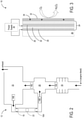
- FIG. 2 shows a schematic diagram of the airflow passage 12 in the aircraft 100 with an air purification element 16 positioned in the airflow passage 12 according to the present disclosure.
- the air purification element 16 is configured to produce a peroxide (e.g., hydrogen peroxide (H 2 O 2 )) to oxidize contaminants in the air 14 flowing through the airflow passage 12.
- a peroxide e.g., hydrogen peroxide (H 2 O 2 )
- H 2 O 2 hydrogen peroxide
- air in the cabin 10 is a mixture of air from an outside environment, such as engine bleed air, and air recirculated from the cabin 10.
- a flow of air 14A from the outside environment passes through an air conditioning pack 18, where it is compressed, cooled, and expanded, to a mixing manifold 20, where it is mixed with a flow of air 14B that is recirculated from the cabin 10.
- the flow of air 14B that is recirculated from the cabin 10 is extracted from the cabin 10, passes through the air purification element 16 and the HEPA filter 22. Additionally or alternatively to the air purification element 16, the flow of air 14B can pass through the air purification element 16A located downstream of the HEPA filter 22.
- the filtered and purified flow of air 14B from the cabin 10 then enters the mixing manifold 20 to be mixed with a flow of air 14A from the outside environment, and the resulting mixed flow of air 14C is directed into the cabin 10, thereby providing decontaminated air to passengers seated in the cabin 10 of the aircraft 100.
- FIG. 3 shows a schematic diagram of the air purification element 16.
- the air purification element 16 includes a peroxide-generating structure 24 comprising a first electrode 26 separated from a second electrode 28 by an ionically conductive matrix 30.
- the peroxide-generating structure 24 is configured to produce peroxide from water vapor and oxygen in flow of air 14 in the airflow passage 12 when energized by an energy source.
- the air purification element 16 further includes a matrix 32 (cross hatching) comprising a peroxide-activating catalyst 34 (schematically illustrated by stars) that is configured to activate the peroxide produced by lowering an activation energy for the peroxide to react with airborne contaminants.
- the air purification element 16 is constructed as layers on a base substrate 36, with the matrix 32 comprising the peroxide-activating catalyst 34 being an outermost layer from the substrate 36 so as to allow the contaminants to contact peroxide activated by the peroxide-activating catalyst 34.
- the peroxide-activating catalyst 34 can be alternatively positioned, such as distributed throughout the ionically conductive matrix 30.
- the air purification element 16 produces H 2 O 2 upon the application of a voltage from a power supply 38 across the first electrode 26 and the second electrode 28.
- the first electrode 26 can be configured as an anode
- the second electrode 28 can be configured as a cathode.
- H 2 O 2 can be produced at the anode by the oxidation of the water vapor in the air 14 in the airflow passage 12.
- H 2 O 2 can be produced at the cathode by the reduction of oxygen in the air 14.
- the produced peroxide then diffuses through the ionically conductive matrix 30 to the matrix 32 comprising the peroxide-activating catalyst 34.
- the peroxide-activating catalyst 34 can comprise, for example, complexes of ethylenediaminetetraacetic acid (EDTA) with metals such as iron, tetra-amido macrocyclic ligand (TAML ® ) complexes with metals such as iron, manganese gluconate, sodium hypochlorite, N- [4-(triethlyammoniomethyl)benzoyl] -caprolactam chloride, nonanoyloxybenzene sulfonate, porphyrins, phthalocyanines, ruthenium oxide, indium oxide, quinones, and the like, for example.
- EDTA ethylenediaminetetraacetic acid
- TAML ® tetra-amido macrocyclic ligand
- the resulting activated peroxide can then migrate to the surface of the air purification element 16 where it contacts and oxidizes contaminants in the airflow passage 12.
- an electrocatalyst can be bound to the cathode to catalyze the formation of hydrogen ions.
- a hydrogen peroxide scavenger or a peroxide removal agent such as ascorbic acid can be provided in the airflow passage 12 downstream of the air purification element 16 to reduce or remove peroxide from the flow of air 14 before it is circulated back into an environment.
- the air purification element can have any suitable configuration, based upon a desired end use. Example implementations of the air purification element 16 are described below with reference to FIGS. 4-11 .
- the air purification element 16 can be configured as an integrated unit designed to be removably placed in the airflow passage 12. Additionally or alternatively, the air purification element 16 can be positioned in a housing configured to fit in the airflow passage 12. Further, the air purification element 16 can be configured to be replaceable (e.g. as a consumable item).
- the air purification element 16 can be configured in various ways and is adaptable for use in many environments, examples of which include aircraft, personal respiration devices, and habitable fixed structures (e.g. buildings such as hospitals, schools, offices, shopping centers, restaurants, public transportation vehicles, air conditioning units, and laboratories).
- the air purification element 16 is configured as an air purification element 416 that comprises a plurality of channels 40 through which an airflow can pass.
- the peroxide-generating structure 24 is located in each channel of the plurality of channels.
- each channel is formed by layering the individual layers of the peroxide-generating structure 24 on the base substrate 36, as described above with reference to FIG. 3 , such that the matrix 32 with the peroxide-activating catalyst 34 is exposed to airflow within each channel 40.
- the channels 40 can be arranged horizontally, as shown in FIG. 4 , vertically or diagonally, or in any other suitable orientation with respect to an airflow passage in which they are used.
- the channels 40 are shown comprise a rectangular cross-section, the channels 40 can have any other suitable shape, and the shape can vary along a direction of airflow.
- the channels 40 are contained within a removable unit (e.g. a housing) configured to be placed within another airflow passage.
- the housing 46 can comprise electrical contacts (+, -) configured to contact complementary electrical contacts in an airflow passage.
- the housing can be configured to hold one or more batteries (not shown) as a power supply.
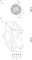
- FIGS. 5 and 6 show the air purification element 16 configured as an example air purification element 516 in which peroxide-generating structure 24 is configured as rod-shaped structures 42 and vane-shaped structures 44.
- the first electrode 26 is at least partially surrounded by the second electrode 28.
- the ionically conductive matrix 30 is disposed therebetween, and the matrix 32 containing the peroxide-activating catalyst 34 is arranged on an outer surface (S3) of the second electrode 28.
- a plurality of rod- and/or vane-shaped structures 42, 44 can be arranged in a housing 46 that is configured to be removably inserted into the airflow passage 12.
- the housing 46 can include a battery compartment and/or electrical contacts for connecting to a power supply, as described above with regard to FIG. 4 .
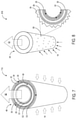
- FIG. 7 shows the air purification element 16 configured as an air purification element 716.
- an air purification element 716 comprises a hollow fiber 48 of a porous material 50.
- the first electrode 26 positioned on a first surface S1 of the hollow fiber 48 (here shown as an inner surface)
- the second electrode 28 is positioned on a second surface S2 of the hollow fiber 48
- the ionically conductive matrix 30 is positioned in the porous material 50 between the first and second electrodes 26, 28.
- the matrix 32 containing the peroxide-activating catalyst 34 is arranged on an outer surface (S3) of the second electrode 28 so as to be exposed to the flow of air 14 in the airflow passage 12.
- One or more hollow fibers 48 can be positioned in the airflow passage 12 such that contaminants in the air 14 flowing through the airflow passage 12 contact the activated peroxide at the surface of the air purification element 716 and are oxidized. In this configuration, purified air 52 flows out from the center of the hollow fiber 48, as shown in FIG. 7 .
- FIG. 8 shows the air purification element 16 is configured as an air purification element 816 that comprises a hollow fiber 54 of a porous material 55 that includes a plurality of pores 56.
- the peroxide-generating structure 24 comprises a layered structure built on the substrate 36, with the first and second electrodes 26, 28 separated by the ionically conductive matrix 30.
- the matrix 32 containing the peroxide-activating catalyst 34 arranged on an outer surface (S3) of the second electrode 28. Similar to the implementation of the hollow fiber 48 described above with reference to FIG.
- one or more hollow fibers 54 can be positioned in the airflow passage 12 such that contaminants in the air 14 flowing through the airflow passage 12 can contact the activated peroxide at the surface of the air purification element 816 and be oxidized. Purified air 52 flows out from the center of the hollow fiber 54.
- a channel in an air purification element can have a configuration that helps to achieve turbulent flow so that air in a center of the channel flows toward the surface(s) of the channel and is exposed to activated peroxide.
- FIGS. 9-11 show examples of such structures.
- FIG. 9 shows the air purification element 16 configured as an air purification element 916 comprising a curved airflow channel 58 to create turbulent airflow.
- FIG. 10 shows the air purification element 16 configured as an air purification element 1016 comprising a surface 60 having a texture to create turbulent airflow.
- Channel 58 and surface 60 can be used, for example, in the layered air purification element of FIG. 4 .
- FIG. 9 shows the air purification element 16 configured as an air purification element 916 comprising a curved airflow channel 58 to create turbulent airflow.
- FIG. 10 shows the air purification element 16 configured as an air purification element 1016 comprising a surface 60 having a texture to create turbulent airflow.
- Channel 58 and surface 60 can be used,
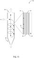
- the air purification element 16 is configured as an air purification element 1116 that comprises a channel 62 having a tapered end 64 configured to create a vortex in airflow through the channel 62.
- the peroxide-generating structure 24 is formed on the substrate 36 and overlaid with the matrix 32 comprising the peroxide-activating catalyst 34 such that contaminants in the flow of air 14 contact the activated peroxide and are oxidized.
- FIG. 12 shows the air purification element 16 configured as an example air purification element 1216 in a personal respiration device 1200.
- the air purification element 1216 can be enclosed in a housing that is configured to be coupled with the personal respiration device 1200.
- the personal respiration device 1200 can be reusable or disposable.
- the air purification element 1216 preferably comprises a battery 66.
- the first electrode 26 can be configured as an anode comprising sacrificial zinc or silver that is oxidized
- the second electrode 28 can be configured as a carbon cathode that reduces oxygen to form peroxide.
- the personal respiration device 1200 is illustrated as a half mask respirator, it will be appreciated that the personal respiration device 1200 can be configured as any other suitable type of personal respiration device, such as a full mask respirator, a powered air-purifying respirator (PAPR), a supplied air respirator (SAR), a self-contained breathing apparatus (SCBA), gas masks, and the like, for example. Additionally or alternatively, the air purification element 16 can be inserted in cartridges or cannisters that are used in conjunction with a personal respiration device.
- PAPR powered air-purifying respirator
- SAR supplied air respirator
- SCBA self-contained breathing apparatus
- gas masks gas masks
- the air purification element 16 can be inserted in cartridges or cannisters that are used in conjunction with a personal respiration device.
- FIG. 13 shows the air purification element 16 configured as an air purification element 1316 designed for use with a habitable fixed structure 1300.
- the air purification element 1316 can be enclosed in an air conditioning unit 68 positioned outside of the habitable fixed structure 1300 and configured to deliver decontaminated, conditioned air to the habitable fixed structure 1300.
- the air purification element 1316 can be enclosed in a housing and can comprise electrical contacts configured to engage with a power supply included in the air conditioning unit. While the habitable fixed structure 1300 in FIG. 13 is illustrated as a tent, it will be appreciated that the habitable fixed structure 1300 can be configured as a hangar, trailer, barracks, school, office building, hospital, community center, recreational facility, or any other suitable structure.
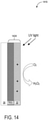
- FIG. 14 shows the air purification element 16 configured as an air purification element 1416 in which the peroxide-generating structure 24 is configurated as a peroxide-generating structure 1424 that comprises a photochemical peroxide generator.
- the photochemical air purification element 1416 can include a matrix 32 comprising the peroxide-activating catalyst 34 that is configured to activate the peroxide.
- the peroxide-activating catalyst 34 comprises TAML ® .
- the peroxide-activating catalyst 34 can comprise any other suitable complex or compound, such as those discussed above with reference to FIG. 3 .
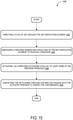
- FIG. 15 is a flow diagram showing an example method 1500 of oxidizing contaminants in air flowing through an airflow passage.
- the method 1500 is an efficient and effective way to purify air of airborne contaminants via oxidation.
- the following description of method 1500 is provided with reference to the air purification element 16 described above and shown in FIG. 3 , with examples shown in FIGS. 4-11 . It will be appreciated that method 1500 can also be performed in other contexts using other suitable components.
- the method 1500 includes directing a flow of air through the air purification element.
- the method 1500 includes energizing a peroxide-generating structure of the air purification element to produce a peroxide from water vapor and oxygen in the airflow passage.
- the peroxide-generating structure can be energized via an applied electrical potential, while in other examples the peroxide-generating structure can be energized via incident light.
- the method 1500 includes activating, via a peroxide-activating catalyst, at least some of the peroxide produced.
- the method 1500 includes contacting the air flowing through the airflow passage with the peroxide activated to oxidize contaminants.
- One aspect provides a system comprising an airflow passage and an air purification element positioned in the airflow passage.
- the airflow passage is configured to confine a flow of air and direct the flow of air toward a space, and the air purification element is configured to produce a peroxide to oxidize contaminants in air flowing through the airflow passage.
- the air purification element includes a peroxide-generating structure and a matrix containing a peroxide-activating catalyst.
- the peroxide-generating structure is configured to produce the peroxide from a water vapor and oxygen in the air within the airflow passage when energized by an energy source, and the matrix containing the peroxide-activating catalyst is configured to activate the peroxide produced and allow the contaminants to contact peroxide activated by the peroxide-activating catalyst.
- the peroxide-generating structure comprises an electrode pair separated by an ionically conductive matrix, and an electrocatalyst.
- the peroxide-generating structure comprises titanium dioxide.
- the system comprises an aircraft, and the airflow passage in which the air purification element is positioned is configured to provide air to a cabin of the aircraft.
- the system comprises a personal respiration device.
- the system comprises a habitable fixed structure.
- the air purification element comprises an integrated unit configured to be removably placed in the airflow passage.
- the air purification element comprises a plurality of channels for airflow, and the peroxide-generating structure and the peroxide-activating catalyst are located in each channel of the plurality of channels.
- the air purification element comprises a surface having a texture to create turbulent airflow.
- the air purification element comprises a curved airflow channel to create turbulent airflow.
- the air purification element comprises a hollow fiber of a porous material
- the peroxide-generating structure comprises a first electrode positioned on a first surface of the hollow fiber, a second electrode positioned on a second surface of the hollow fiber, and an ionically conductive matrix positioned between the first electrode and the second electrode in the porous material; and the matrix containing the peroxide-activating catalyst is arranged on a surface of the second electrode.
- the air purification element comprises a hollow fiber of a porous material comprising a plurality of pores
- the peroxide-generating structure comprises, in each of one or more pores of the plurality of pores, a first electrode and a second electrode separated by an ionically conductive matrix.
- the matrix containing the peroxide-activating catalyst is arranged on an outer surface of the second electrode.
- the air purification element comprises a channel configured to create a vortex in airflow through the channel.
- the peroxide-generating structure comprises one or more of a rod-shaped structure and a vane-shaped structure having a first electrode at least partially surrounded by a second electrode with an ionically conductive matrix disposed therebetween, and the matrix containing the peroxide-activating catalyst is arranged on a surface of the second electrode.
- an aircraft comprising a cabin, an airflow passage, and an air purification element positioned in the airflow passage.
- the airflow passage is configured to confine a flow of air and direct the flow of air toward a space, and the air purification element is configured to produce a peroxide to oxidize contaminants in air flowing through the airflow passage.
- the air purification element includes a peroxide-generating structure and a matrix containing a peroxide-activating catalyst.
- the peroxide-generating structure is configured to produce the peroxide from a water vapor and oxygen in the air within the airflow passage.
- the peroxide-generating structure includes a first electrode separated from a second electrode by an ionically conductive matrix and is configured to produce the peroxide upon application of a voltage across the first electrode and the second electrode.
- the matrix containing the peroxide-activating catalyst is configured to activate the peroxide produced and is positioned to allow the contaminants to contact peroxide activated by the peroxide-activating catalyst.
- Another aspect provides a method of oxidizing contaminants in air flowing through an airflow passage via an air purification element.
- the method comprises directing a flow of air through the air purification element, energizing a peroxide-generating structure of the air purification element to produce a peroxide from water vapor and oxygen in the airflow passage, activating, via a peroxide-activating catalyst, at least some of the peroxide produced, and contacting the air flowing through the airflow passage with the activated peroxide to oxidize the contaminants.
- energizing the peroxide-generating structure comprises applying a voltage across a pair of electrodes, and generating peroxide via an electrocatalyst.
- energizing the peroxide-generating structure comprises illuminating the peroxide-generating structure with ultraviolet light.
- directing the flow of air through the air purification element comprises creating a vortex in the air flowing through the airflow passage.
- directing the flow of air through the air purification element comprises flowing the air through a plurality of airflow channels in the air purification element.
- directing the flow of air through the air purification element comprises flowing the air through one or more hollow porous fibers.
- the replaceable air purification element comprises a housing, a peroxide-generating structure, and a matrix containing a peroxide-activating catalyst.
- the housing is configured to be removably inserted into an airflow passage that confines a flow of air and directs the flow of air toward a space.
- the peroxide-generating structure is positioned within the housing and is configured to produce a peroxide from a water vapor and oxygen in the air within the airflow passage when energized by an energy source.
- the matrix containing a peroxide-activating catalyst is configured to activate the peroxide produced and allow contaminants in the flow of air to contact peroxide activated by the peroxide-activating catalyst.
- the peroxide-generating structure comprises a pair of electrodes separated by an ionically conductive matrix and an electrocatalyst, and the replaceable air purification element further comprises electrical contacts.
- the peroxide-generating structure comprises titanium dioxide.
- the housing is configured to fit within an airflow passage of an aircraft.
- the housing is configured to be coupled with a personal respiration device.
- the air purification element comprises a plurality of channels for airflow, and the peroxide-generating structure and the peroxide-activating catalyst are located in each channel of the plurality of channels.
- the air purification element comprises a surface having a texture to create turbulent airflow.
- the air purification element comprises a curved airflow channel to create turbulent airflow.
- the air purification element comprises a hollow fiber of a porous material.
- the air purification element comprises a channel having a tapered end configured to create a vortex in airflow through the channel.
- the peroxide-generating structure comprises one or more of a rod-shaped structure and a vane-shaped structure having a first electrode at least partially surrounded by a second electrode with an ionically conductive matrix disposed therebetween.
- the peroxide-generating structure comprises a battery.
Landscapes
- Chemical & Material Sciences (AREA)
- Health & Medical Sciences (AREA)
- Engineering & Computer Science (AREA)
- Chemical Kinetics & Catalysis (AREA)
- General Health & Medical Sciences (AREA)
- Veterinary Medicine (AREA)
- Public Health (AREA)
- Animal Behavior & Ethology (AREA)
- Life Sciences & Earth Sciences (AREA)
- Epidemiology (AREA)
- Environmental & Geological Engineering (AREA)
- Electrochemistry (AREA)
- Materials Engineering (AREA)
- Metallurgy (AREA)
- Organic Chemistry (AREA)
- General Chemical & Material Sciences (AREA)
- Oil, Petroleum & Natural Gas (AREA)
- Analytical Chemistry (AREA)
- Biomedical Technology (AREA)
- Pulmonology (AREA)
- Inorganic Chemistry (AREA)
- Aviation & Aerospace Engineering (AREA)
- Toxicology (AREA)
- Dispersion Chemistry (AREA)
- Catalysts (AREA)
- Disinfection, Sterilisation Or Deodorisation Of Air (AREA)
Abstract
Description
- The present disclosure relates generally to air purification, and more specifically, to peroxide-generating air purification elements for treating airflow into enclosed spaces.
- Air contaminated with pathogens and/or toxins poses a significant risk to human health, as people may become ill upon inhalation of such contaminants. Thus, disinfection of air such air may help to reduce the impact of such contaminants on human health. However, conventional disinfectant methods have limitations. For example, conventional disinfectants can include undesirable substances. Further, filters can become clogged over time, and may be only partially effective at removing contaminants from air.
- Activated peroxide can destroy microorganisms such as bacteria, viruses, and fungi, toxins produced by microorganisms, and myriad chemical agents, yet remains safe for human use.
- To address the above issues, according to one aspect of the present disclosure, a system is provided herein. In this aspect, the system includes an airflow passage and an air purification element. The airflow passage is configured to confine a flow of air and direct the flow of air toward a space. The air purification element is positioned in the airflow passage and configured to produce a peroxide to oxidize contaminants in air flowing through the airflow passage. The air purification element includes a peroxide-generating structure and a matrix containing a peroxide-activating catalyst configured to activate peroxide produced. The air purification element is configured to produce the peroxide from a water vapor and oxygen in the air within the airflow passage when energized by an energy source, and the matrix is configured to allow the contaminants to contact peroxide activated by the peroxide-activating catalyst.
- Another aspect of the present disclosure relates to an aircraft. In this aspect, the aircraft includes a cabin, an airflow passage, and an air purification element. The airflow passage is configured to confine a flow of air and direct the flow of air toward the cabin. The air purification element is positioned in the airflow passage and configured to produce a peroxide to oxidize contaminants in air flowing through the airflow passage. The air purification element includes a peroxide-generating structure and a matrix. The peroxide-generating structure is configured to produce the peroxide from water vapor and oxygen in the airflow passage. The peroxide-generating structure includes a first electrode separated from a second electrode by an ionically conductive matrix and is configured to produce the peroxide upon application of a voltage across the first electrode and the second electrode. The matrix includes a peroxide-activating catalyst that activates the peroxide produced and is positioned to allow the contaminants to contact peroxide activated by the peroxide-activating catalyst.
- Another aspect of the present disclosure relates to a method of oxidizing contaminants in air flowing through an airflow passage via an air purification element. In this aspect, the method includes directing a flow of air through the air purification element. The method includes energizing a peroxide-generating structure of the air purification element to produce a peroxide from water vapor and oxygen in the airflow passage. The method further includes activating, via a peroxide-activating catalyst, at least some of the peroxide produced, and contacting the air flowing through the airflow passage with the activated peroxide to oxidize the contaminants.
- Still another aspect of the present disclosure relates to a replaceable air purification element. The replaceable air purification element includes a housing, a peroxide-generating structure, and a matrix. The housing is configured to be removably inserted into an airflow passage that confines a flow of air and directs the flow of air toward a space. The peroxide-generating structure is positioned within the housing and is configured to produce a peroxide from water vapor and oxygen in the air within the airflow passage when energized by an energy source. The matrix includes a peroxide-activating catalyst that activates the peroxide produced and is configured to allow contaminants in the flow of air to contact peroxide activated by the peroxide-activating catalyst.
- The features, functions, and advantages discussed can be provided independently in various examples or may be combined in yet other examples, further aspects of which are described in detail with reference to the following description and drawings.
-
-
FIG. 1 shows an example aircraft, and illustrates airflow from a duct into a cabin according to the present disclosure. -
FIG. 2 shows a schematic diagram of an example airflow system for an aircraft with an air purification element positioned in an airflow passage, according to the present disclosure. -
FIG. 3 shows a schematic diagram of an example air purification element according to the present disclosure. -
FIG. 4 schematically shows an example air purification element comprising a layered structure according to the present disclosure. -
FIG. 5 shows an example air purification element comprising peroxide-generating structures configured as rods according to the present disclosure. -
FIG. 6 shows a sectional view of an example peroxide-generating structure configured as a rod according to the present disclosure. -
FIG. 7 shows an example air purification element configured as a hollow fiber of a porous material according to the present disclosure. -
FIG. 8 shows an example air purification element configured as a hollow fiber comprising a plurality of pores according to the present disclosure. -
FIG. 9 shows an air purification element configured as a curved airflow channel according to the present disclosure. -
FIG. 10 shows an air purification element configured as a textured airflow channel according to the present disclosure. -
FIG. 11 shows an air purification element configured as a channel that creates a vortex according to the present disclosure. -
FIG. 12 shows an air purification element in a personal respiration device according to the present disclosure. -
FIG. 13 shows an air purification element in a habitable fixed structure according to the present disclosure. -
FIG. 14 shows an example air purification element utilizing ultraviolet light to energize a peroxide-generating structure according to the present disclosure. -
FIG. 15 is a flow diagram illustrating an example method of oxidizing contaminants in air via an air purification element according to the present disclosure. - Selected examples will now be explained with reference to the drawings, wherein like reference characters designate corresponding or identical elements throughout the various drawings. The following descriptions of the disclosed examples are provided for illustration only and not for the purpose of limiting the disclosure as defined by the appended claims and their equivalents.
-
FIG. 1 shows anaircraft 100, with a magnified view of acabin 10 and anairflow passage 12 configured to confine a flow ofair 14 and direct it toward thecabin 10. In many aircraft, at least a portion of the flow ofair 14 in theairflow passage 12 input to thecabin 10 is recirculated from thecabin 10. A high efficiency particulate (HEPA) filter or the like may be placed in theairflow passage 12 to trap airborne pathogens and other particulates in the flow ofair 14 is filtered before it is recirculated. However, HEPA filtration does not provide absolute sterilization, as this technology is not enabled for the destruction of pathogens. Additionally, HEPA filters can become clogged. Further, HEPA filters do not filter gaseous contaminants from the flow ofair 14. As such, activated peroxide is promising for decontaminating air in occupied spaces. However, challenges exist in developing effective and efficient systems and methods for employing activated peroxide to treat contaminants in air. - Thus, examples are disclosed that relate to the use of peroxide-generating air purification elements to inactivate and destroy a variety of airborne contaminants, including pathogens and chemical contaminants.
-
FIG. 2 shows a schematic diagram of theairflow passage 12 in theaircraft 100 with anair purification element 16 positioned in theairflow passage 12 according to the present disclosure. As described in detail below, theair purification element 16 is configured to produce a peroxide (e.g., hydrogen peroxide (H2O2)) to oxidize contaminants in theair 14 flowing through theairflow passage 12. The location of theair purification element 16 is optional, and an alternative or additional location for an air purification element is shown at 16A. - Typically, air in the
cabin 10 is a mixture of air from an outside environment, such as engine bleed air, and air recirculated from thecabin 10. As illustrated, a flow ofair 14A from the outside environment passes through anair conditioning pack 18, where it is compressed, cooled, and expanded, to a mixingmanifold 20, where it is mixed with a flow ofair 14B that is recirculated from thecabin 10. The flow ofair 14B that is recirculated from thecabin 10 is extracted from thecabin 10, passes through theair purification element 16 and theHEPA filter 22. Additionally or alternatively to theair purification element 16, the flow ofair 14B can pass through theair purification element 16A located downstream of theHEPA filter 22. The filtered and purified flow ofair 14B from thecabin 10 then enters the mixingmanifold 20 to be mixed with a flow ofair 14A from the outside environment, and the resulting mixed flow of air 14C is directed into thecabin 10, thereby providing decontaminated air to passengers seated in thecabin 10 of theaircraft 100. -
FIG. 3 shows a schematic diagram of theair purification element 16. Theair purification element 16 includes a peroxide-generatingstructure 24 comprising afirst electrode 26 separated from asecond electrode 28 by an ionicallyconductive matrix 30. The peroxide-generatingstructure 24 is configured to produce peroxide from water vapor and oxygen in flow ofair 14 in theairflow passage 12 when energized by an energy source. Theair purification element 16 further includes a matrix 32 (cross hatching) comprising a peroxide-activating catalyst 34 (schematically illustrated by stars) that is configured to activate the peroxide produced by lowering an activation energy for the peroxide to react with airborne contaminants. In some implementations, theair purification element 16 is constructed as layers on abase substrate 36, with thematrix 32 comprising the peroxide-activatingcatalyst 34 being an outermost layer from thesubstrate 36 so as to allow the contaminants to contact peroxide activated by the peroxide-activatingcatalyst 34. However, it will be appreciated that the peroxide-activatingcatalyst 34 can be alternatively positioned, such as distributed throughout the ionicallyconductive matrix 30. - In the example of
FIG. 3 , theair purification element 16 produces H2O2 upon the application of a voltage from apower supply 38 across thefirst electrode 26 and thesecond electrode 28. Thefirst electrode 26 can be configured as an anode, and thesecond electrode 28 can be configured as a cathode. In the presence of a catalyst, e.g., CaSnO3, H2O2 can be produced at the anode by the oxidation of the water vapor in theair 14 in theairflow passage 12. Additionally or alternatively, H2O2 can be produced at the cathode by the reduction of oxygen in theair 14. The produced peroxide then diffuses through the ionicallyconductive matrix 30 to thematrix 32 comprising the peroxide-activatingcatalyst 34. The peroxide-activatingcatalyst 34 can comprise, for example, complexes of ethylenediaminetetraacetic acid (EDTA) with metals such as iron, tetra-amido macrocyclic ligand (TAML®) complexes with metals such as iron, manganese gluconate, sodium hypochlorite, N- [4-(triethlyammoniomethyl)benzoyl] -caprolactam chloride, nonanoyloxybenzene sulfonate, porphyrins, phthalocyanines, ruthenium oxide, indium oxide, quinones, and the like, for example. The resulting activated peroxide can then migrate to the surface of theair purification element 16 where it contacts and oxidizes contaminants in theairflow passage 12. In some implementations, an electrocatalyst can be bound to the cathode to catalyze the formation of hydrogen ions. If desired, a hydrogen peroxide scavenger or a peroxide removal agent such as ascorbic acid can be provided in theairflow passage 12 downstream of theair purification element 16 to reduce or remove peroxide from the flow ofair 14 before it is circulated back into an environment. - The air purification element can have any suitable configuration, based upon a desired end use. Example implementations of the
air purification element 16 are described below with reference toFIGS. 4-11 . In some implementations, theair purification element 16 can be configured as an integrated unit designed to be removably placed in theairflow passage 12. Additionally or alternatively, theair purification element 16 can be positioned in a housing configured to fit in theairflow passage 12. Further, theair purification element 16 can be configured to be replaceable (e.g. as a consumable item). Theair purification element 16 can be configured in various ways and is adaptable for use in many environments, examples of which include aircraft, personal respiration devices, and habitable fixed structures (e.g. buildings such as hospitals, schools, offices, shopping centers, restaurants, public transportation vehicles, air conditioning units, and laboratories). - In the example of
FIG. 4 , theair purification element 16 is configured as anair purification element 416 that comprises a plurality ofchannels 40 through which an airflow can pass. The peroxide-generatingstructure 24 is located in each channel of the plurality of channels. In this implementation, each channel is formed by layering the individual layers of the peroxide-generatingstructure 24 on thebase substrate 36, as described above with reference toFIG. 3 , such that thematrix 32 with the peroxide-activatingcatalyst 34 is exposed to airflow within eachchannel 40. Thechannels 40 can be arranged horizontally, as shown inFIG. 4 , vertically or diagonally, or in any other suitable orientation with respect to an airflow passage in which they are used. As the flow ofair 14 is directed through theairflow passage 12, contaminants in the air contact activated peroxide at the surface of theair purification element 416 and are oxidized. While thechannels 40 are shown comprise a rectangular cross-section, thechannels 40 can have any other suitable shape, and the shape can vary along a direction of airflow. In some examples, thechannels 40 are contained within a removable unit (e.g. a housing) configured to be placed within another airflow passage. In such examples, thehousing 46 can comprise electrical contacts (+, -) configured to contact complementary electrical contacts in an airflow passage. In other examples, the housing can be configured to hold one or more batteries (not shown) as a power supply. -
FIGS. 5 and 6 show theair purification element 16 configured as an exampleair purification element 516 in which peroxide-generatingstructure 24 is configured as rod-shapedstructures 42 and vane-shapedstructures 44. In this configuration, as shown in the sectional view of the rod-shapedstructure 40 inFIG. 6 , thefirst electrode 26 is at least partially surrounded by thesecond electrode 28. The ionicallyconductive matrix 30 is disposed therebetween, and thematrix 32 containing the peroxide-activatingcatalyst 34 is arranged on an outer surface (S3) of thesecond electrode 28. A plurality of rod- and/or vane-shapedstructures housing 46 that is configured to be removably inserted into theairflow passage 12. When the flow ofair 14 is directed through theairflow passage 12, contaminants in the air contact activated peroxide at the surface of theair purification element 16 and are destroyed via oxidation. Thehousing 46 can include a battery compartment and/or electrical contacts for connecting to a power supply, as described above with regard toFIG. 4 . -
FIG. 7 shows theair purification element 16 configured as anair purification element 716. In this example, anair purification element 716 comprises ahollow fiber 48 of aporous material 50. Thefirst electrode 26 positioned on a first surface S1 of the hollow fiber 48 (here shown as an inner surface), thesecond electrode 28 is positioned on a second surface S2 of thehollow fiber 48, and the ionicallyconductive matrix 30 is positioned in theporous material 50 between the first andsecond electrodes matrix 32 containing the peroxide-activatingcatalyst 34 is arranged on an outer surface (S3) of thesecond electrode 28 so as to be exposed to the flow ofair 14 in theairflow passage 12. One or morehollow fibers 48 can be positioned in theairflow passage 12 such that contaminants in theair 14 flowing through theairflow passage 12 contact the activated peroxide at the surface of theair purification element 716 and are oxidized. In this configuration, purifiedair 52 flows out from the center of thehollow fiber 48, as shown inFIG. 7 . -
FIG. 8 shows theair purification element 16 is configured as anair purification element 816 that comprises ahollow fiber 54 of a porous material 55 that includes a plurality ofpores 56. As illustrated schematically in the magnified view ofFIG. 8 , in each of one ormore pores 56 of the plurality ofpores 56, the peroxide-generatingstructure 24 comprises a layered structure built on thesubstrate 36, with the first andsecond electrodes conductive matrix 30. Thematrix 32 containing the peroxide-activatingcatalyst 34 arranged on an outer surface (S3) of thesecond electrode 28. Similar to the implementation of thehollow fiber 48 described above with reference toFIG. 7 , one or morehollow fibers 54 can be positioned in theairflow passage 12 such that contaminants in theair 14 flowing through theairflow passage 12 can contact the activated peroxide at the surface of theair purification element 816 and be oxidized.Purified air 52 flows out from the center of thehollow fiber 54. - In some implementations, a channel in an air purification element can have a configuration that helps to achieve turbulent flow so that air in a center of the channel flows toward the surface(s) of the channel and is exposed to activated peroxide.
FIGS. 9-11 show examples of such structures. First,FIG. 9 shows theair purification element 16 configured as anair purification element 916 comprising acurved airflow channel 58 to create turbulent airflow.FIG. 10 shows theair purification element 16 configured as anair purification element 1016 comprising asurface 60 having a texture to create turbulent airflow.Channel 58 andsurface 60 can be used, for example, in the layered air purification element ofFIG. 4 . InFIG. 11 , theair purification element 16 is configured as anair purification element 1116 that comprises a channel 62 having atapered end 64 configured to create a vortex in airflow through the channel 62. As illustrated in the magnified views of thecurved airflow channel 58 ofFIG. 9 , thetextured surface 60 ofFIG. 10 , and the channel 62 ofFIG. 11 , the peroxide-generatingstructure 24 is formed on thesubstrate 36 and overlaid with thematrix 32 comprising the peroxide-activatingcatalyst 34 such that contaminants in the flow ofair 14 contact the activated peroxide and are oxidized. - In some use-case scenarios, such as biomedical or military applications in which a user may be exposed to airborne pathogens and/or toxins, it can be desirable to include an air purification element in personal protective equipment (PPE), such as a mask, to provide the user with decontaminated air.
FIG. 12 shows theair purification element 16 configured as an exampleair purification element 1216 in apersonal respiration device 1200. In this implementation, theair purification element 1216 can be enclosed in a housing that is configured to be coupled with thepersonal respiration device 1200. Thepersonal respiration device 1200 can be reusable or disposable. When thepersonal respiration device 1200 is designed to be disposable, theair purification element 1216 preferably comprises abattery 66. When implemented as thebattery 66, thefirst electrode 26 can be configured as an anode comprising sacrificial zinc or silver that is oxidized, and thesecond electrode 28 can be configured as a carbon cathode that reduces oxygen to form peroxide. - While the
personal respiration device 1200 is illustrated as a half mask respirator, it will be appreciated that thepersonal respiration device 1200 can be configured as any other suitable type of personal respiration device, such as a full mask respirator, a powered air-purifying respirator (PAPR), a supplied air respirator (SAR), a self-contained breathing apparatus (SCBA), gas masks, and the like, for example. Additionally or alternatively, theair purification element 16 can be inserted in cartridges or cannisters that are used in conjunction with a personal respiration device. - Some emergency situations require rapid deployment of semi-permanent biomedical or military structures in potentially hazardous conditions or conversion of existing permanent structures for emergency use. Such situations include management of a biohazard event, containment of an outbreak, isolation and medical treatment of persons infected with a highly contagious pathogen, and military installation in an area in which biological warfare agents may be used, for example. Accordingly,
FIG. 13 shows theair purification element 16 configured as anair purification element 1316 designed for use with a habitable fixedstructure 1300. In this implementation, theair purification element 1316 can be enclosed in anair conditioning unit 68 positioned outside of the habitable fixedstructure 1300 and configured to deliver decontaminated, conditioned air to the habitable fixedstructure 1300. Theair purification element 1316 can be enclosed in a housing and can comprise electrical contacts configured to engage with a power supply included in the air conditioning unit. While the habitable fixedstructure 1300 inFIG. 13 is illustrated as a tent, it will be appreciated that the habitable fixedstructure 1300 can be configured as a hangar, trailer, barracks, school, office building, hospital, community center, recreational facility, or any other suitable structure. - In other examples, instead of an electrochemical peroxide generator, a photochemical peroxide generator mechanism can be used. For example, the photochemical oxidation of titanium dioxide (TiO2) or other heterogeneous photocatalysts such as ferric oxide (Fe2O3) or zinc oxide (ZnO) with ultraviolet (UV) light in the presence of water and oxygen can produce H2O2. To this end,
FIG. 14 shows theair purification element 16 configured as anair purification element 1416 in which the peroxide-generatingstructure 24 is configurated as a peroxide-generatingstructure 1424 that comprises a photochemical peroxide generator. When the peroxide-generatingstructure 1424 is illuminated with UV light in the presence of water vapor and oxygen in theair flow passage 12, H2O2 is generated. Like theair purification element 16 described above with reference toFIG. 3 , the photochemicalair purification element 1416 can include amatrix 32 comprising the peroxide-activatingcatalyst 34 that is configured to activate the peroxide. In some examples, the peroxide-activatingcatalyst 34 comprises TAML®. In other examples, the peroxide-activatingcatalyst 34 can comprise any other suitable complex or compound, such as those discussed above with reference toFIG. 3 . -
FIG. 15 is a flow diagram showing anexample method 1500 of oxidizing contaminants in air flowing through an airflow passage. Themethod 1500 is an efficient and effective way to purify air of airborne contaminants via oxidation. The following description ofmethod 1500 is provided with reference to theair purification element 16 described above and shown inFIG. 3 , with examples shown inFIGS. 4-11 . It will be appreciated thatmethod 1500 can also be performed in other contexts using other suitable components. - With reference to
FIG. 15 , at 1502, themethod 1500 includes directing a flow of air through the air purification element. At 1504, themethod 1500 includes energizing a peroxide-generating structure of the air purification element to produce a peroxide from water vapor and oxygen in the airflow passage. In some examples, the peroxide-generating structure can be energized via an applied electrical potential, while in other examples the peroxide-generating structure can be energized via incident light. At 1506, themethod 1500 includes activating, via a peroxide-activating catalyst, at least some of the peroxide produced. At 1508, themethod 1500 includes contacting the air flowing through the airflow passage with the peroxide activated to oxidize contaminants. - The following paragraphs provide additional support for the claims of the subject application. One aspect provides a system comprising an airflow passage and an air purification element positioned in the airflow passage. The airflow passage is configured to confine a flow of air and direct the flow of air toward a space, and the air purification element is configured to produce a peroxide to oxidize contaminants in air flowing through the airflow passage. The air purification element includes a peroxide-generating structure and a matrix containing a peroxide-activating catalyst. The peroxide-generating structure is configured to produce the peroxide from a water vapor and oxygen in the air within the airflow passage when energized by an energy source, and the matrix containing the peroxide-activating catalyst is configured to activate the peroxide produced and allow the contaminants to contact peroxide activated by the peroxide-activating catalyst. In this aspect, additionally or alternatively, the peroxide-generating structure comprises an electrode pair separated by an ionically conductive matrix, and an electrocatalyst. In this aspect, additionally or alternatively, the peroxide-generating structure comprises titanium dioxide. In this aspect, additionally or alternatively, the system comprises an aircraft, and the airflow passage in which the air purification element is positioned is configured to provide air to a cabin of the aircraft. In this aspect, additionally or alternatively, the system comprises a personal respiration device. In this aspect, additionally or alternatively, the system comprises a habitable fixed structure. In this aspect, additionally or alternatively, the air purification element comprises an integrated unit configured to be removably placed in the airflow passage. In this aspect, additionally or alternatively, the air purification element comprises a plurality of channels for airflow, and the peroxide-generating structure and the peroxide-activating catalyst are located in each channel of the plurality of channels. In this aspect, additionally or alternatively, the air purification element comprises a surface having a texture to create turbulent airflow. In this aspect, additionally or alternatively, the air purification element comprises a curved airflow channel to create turbulent airflow. In this aspect, additionally or alternatively, the air purification element comprises a hollow fiber of a porous material; the peroxide-generating structure comprises a first electrode positioned on a first surface of the hollow fiber, a second electrode positioned on a second surface of the hollow fiber, and an ionically conductive matrix positioned between the first electrode and the second electrode in the porous material; and the matrix containing the peroxide-activating catalyst is arranged on a surface of the second electrode. In this aspect, additionally or alternatively, the air purification element comprises a hollow fiber of a porous material comprising a plurality of pores, and the peroxide-generating structure comprises, in each of one or more pores of the plurality of pores, a first electrode and a second electrode separated by an ionically conductive matrix. The matrix containing the peroxide-activating catalyst is arranged on an outer surface of the second electrode. In this aspect, additionally or alternatively, the air purification element comprises a channel configured to create a vortex in airflow through the channel. In this aspect, additionally or alternatively, the peroxide-generating structure comprises one or more of a rod-shaped structure and a vane-shaped structure having a first electrode at least partially surrounded by a second electrode with an ionically conductive matrix disposed therebetween, and the matrix containing the peroxide-activating catalyst is arranged on a surface of the second electrode.
- Another aspect provides an aircraft comprising a cabin, an airflow passage, and an air purification element positioned in the airflow passage. The airflow passage is configured to confine a flow of air and direct the flow of air toward a space, and the air purification element is configured to produce a peroxide to oxidize contaminants in air flowing through the airflow passage. The air purification element includes a peroxide-generating structure and a matrix containing a peroxide-activating catalyst. The peroxide-generating structure is configured to produce the peroxide from a water vapor and oxygen in the air within the airflow passage. The peroxide-generating structure includes a first electrode separated from a second electrode by an ionically conductive matrix and is configured to produce the peroxide upon application of a voltage across the first electrode and the second electrode. The matrix containing the peroxide-activating catalyst is configured to activate the peroxide produced and is positioned to allow the contaminants to contact peroxide activated by the peroxide-activating catalyst.
- Another aspect provides a method of oxidizing contaminants in air flowing through an airflow passage via an air purification element. The method comprises directing a flow of air through the air purification element, energizing a peroxide-generating structure of the air purification element to produce a peroxide from water vapor and oxygen in the airflow passage, activating, via a peroxide-activating catalyst, at least some of the peroxide produced, and contacting the air flowing through the airflow passage with the activated peroxide to oxidize the contaminants. In this aspect, additionally or alternatively, energizing the peroxide-generating structure comprises applying a voltage across a pair of electrodes, and generating peroxide via an electrocatalyst. In this aspect, additionally or alternatively, energizing the peroxide-generating structure comprises illuminating the peroxide-generating structure with ultraviolet light. In this aspect, additionally or alternatively, directing the flow of air through the air purification element comprises creating a vortex in the air flowing through the airflow passage. In this aspect, additionally or alternatively, directing the flow of air through the air purification element comprises flowing the air through a plurality of airflow channels in the air purification element. In this aspect, additionally or alternatively, directing the flow of air through the air purification element comprises flowing the air through one or more hollow porous fibers.
- Another aspect provides a replaceable air purification element. The replaceable air purification element comprises a housing, a peroxide-generating structure, and a matrix containing a peroxide-activating catalyst. The housing is configured to be removably inserted into an airflow passage that confines a flow of air and directs the flow of air toward a space. The peroxide-generating structure is positioned within the housing and is configured to produce a peroxide from a water vapor and oxygen in the air within the airflow passage when energized by an energy source. The matrix containing a peroxide-activating catalyst is configured to activate the peroxide produced and allow contaminants in the flow of air to contact peroxide activated by the peroxide-activating catalyst. In this aspect, additionally or alternatively, the peroxide-generating structure comprises a pair of electrodes separated by an ionically conductive matrix and an electrocatalyst, and the replaceable air purification element further comprises electrical contacts. In this aspect, additionally or alternatively, the peroxide-generating structure comprises titanium dioxide. In this aspect, additionally or alternatively, the housing is configured to fit within an airflow passage of an aircraft. In this aspect, additionally or alternatively, the housing is configured to be coupled with a personal respiration device. In this aspect, additionally or alternatively, the air purification element comprises a plurality of channels for airflow, and the peroxide-generating structure and the peroxide-activating catalyst are located in each channel of the plurality of channels. In this aspect, additionally or alternatively, the air purification element comprises a surface having a texture to create turbulent airflow. In this aspect, additionally or alternatively, the air purification element comprises a curved airflow channel to create turbulent airflow. In this aspect, additionally or alternatively, the air purification element comprises a hollow fiber of a porous material. In this aspect, additionally or alternatively, the air purification element comprises a channel having a tapered end configured to create a vortex in airflow through the channel. In this aspect, additionally or alternatively, the peroxide-generating structure comprises one or more of a rod-shaped structure and a vane-shaped structure having a first electrode at least partially surrounded by a second electrode with an ionically conductive matrix disposed therebetween. In this aspect, additionally or alternatively, the peroxide-generating structure comprises a battery.
- Further, the disclosure comprises examples according to the following clauses:
-
Clause 1. A system, comprising: an airflow passage configured to confine a flow of air and direct the flow of air toward a space; and an air purification element positioned in the airflow passage and configured to produce a peroxide to oxidize contaminants in air flowing through the airflow passage, the air purification element including: a peroxide-generating structure configured to produce the peroxide from a water vapor and oxygen in the air within the airflow passage when energized by an energy source; and a matrix containing a peroxide-activating catalyst configured to activate peroxide produced, the matrix being configured to allow the contaminants to contact peroxide activated by the peroxide-activating catalyst. -
Clause 2. The system ofClause 1, wherein the peroxide-generating structure comprises an electrode pair separated by an ionically conductive matrix, and an electrocatalyst. -
Clause 3. The system ofClause - Clause 4. The system of any of
Clauses 1 to 3, wherein the system comprises an aircraft, and the airflow passage in which the air purification element is positioned is configured to provide air to a cabin of the aircraft. - Clause 5. The system of any of
Clauses 1 to 3, wherein the system comprises a personal respiration device. - Clause 6. The system of any of
Clauses 1 to 3, wherein the system comprises a habitable fixed structure. - Clause 7. The system of any of
Clauses 1 to 6, wherein the air purification element comprises an integrated unit configured to be removably placed in the airflow passage. - Clause 8. The system of any of
Clauses 1 to 7, wherein the air purification element comprises a plurality of channels for airflow, and the peroxide-generating structure and the peroxide-activating catalyst are located in each channel of the plurality of channels. - Clause 9. The system of any of
Clauses 1 to 8, wherein the air purification element comprises a surface having a texture to create turbulent airflow. -
Clause 10. The system of any ofClauses 1 to 9, wherein the air purification element comprises a curved airflow channel to create turbulent airflow. - Clause 11. The system of any of
Clauses 1 to 10, wherein the air purification element comprises a hollow fiber of a porous material; and the peroxide-generating structure comprises a first electrode positioned on a first surface of the hollow fiber, a second electrode positioned on a second surface of the hollow fiber, and an ionically conductive matrix positioned between the first electrode and the second electrode in the porous material, wherein the matrix containing the peroxide-activating catalyst is arranged on an outer surface of the second electrode. -
Clause 12. The system of any ofClauses 1 to 10, wherein the air purification element comprises a hollow fiber of a porous material comprising a plurality of pores, the peroxide-generating structure comprises, in each of one or more pores of the plurality of pores, a first electrode and a second electrode separated by an ionically conductive matrix, and the matrix containing the peroxide-activating catalyst is arranged on an outer surface of the second electrode. - Clause 13. The system of any of
Clauses 1 to 12, wherein the air purification element comprises a channel configured to create a vortex in airflow through the channel. -
Clause 14. The system of any ofClauses 1 to 13, wherein the peroxide-generating structure comprises one or more of a rod-shaped structure and a vane-shaped structure having a first electrode at least partially surrounded by a second electrode with an ionically conductive matrix disposed therebetween, and the matrix containing the peroxide-activating catalyst is arranged on an outer surface of the second electrode. - Clause 14a. A method of oxidizing contaminants in air flowing through an airflow passage using the air purification element and/or system of any preceding Clause.
- Clause 14b. The method of Clause 14a, comprising the steps of any of
Clauses 16 to 21. - Clause 15. An aircraft, comprising: a cabin; an airflow passage configured to confine a flow of air and direct the flow of air toward the cabin; and an air purification element positioned in the airflow passage and configured to produce a peroxide to oxidize contaminants in air flowing through the airflow passage, the air purification element including: a peroxide-generating structure configured to produce the peroxide from water vapor and oxygen in the airflow passage, the peroxide-generating structure including a first electrode separated from a second electrode by an ionically conductive matrix and being configured to produce the peroxide upon application of a voltage across the first electrode and the second electrode; and a matrix containing a peroxide-activating catalyst configured to activate the peroxide produced, the matrix containing the peroxide-activating catalyst being positioned to allow the contaminants to contact peroxide activated by the peroxide-activating catalyst.
- Clause 15a. An aircraft, comprising: a cabin; and the system of any of
Clauses 1 to 14, wherein the space is the cabin and the peroxide-generating structure includes a first electrode separated from a second electrode by an ionically conductive matrix and being configured to produce the peroxide upon application of a voltage across the first electrode and the second electrode. -
Clause 16. A method of oxidizing contaminants in air flowing through an airflow passage via an air purification element, the method comprising: directing a flow of air through the air purification element; energizing a peroxide-generating structure of the air purification element to produce a peroxide from water vapor and oxygen in the airflow passage; activating, via a peroxide-activating catalyst, at least some of the peroxide produced; and contacting the air flowing through the airflow passage with the activated peroxide to oxidize the contaminants. - Clause 17. The method of
Clause 16, wherein energizing the peroxide-generating structure comprises applying a voltage across a pair of electrodes, and generating peroxide via an electrocatalyst. -
Clause 18. The method ofClause 16, wherein energizing the peroxide-generating structure comprises illuminating the peroxide-generating structure with ultraviolet light. - Clause 19. The method of any of
Clauses 16 to 18, wherein directing the flow of air through the air purification element comprises creating a vortex in the air flowing through the airflow passage. -
Clause 20. The method of any ofClauses 16 to 19, wherein directing the flow of air through the air purification element comprises flowing the air through a plurality of airflow channels in the air purification element. - Clause 21. The method of any of
Clauses 16 to 20, wherein directing the flow of air through the air purification element comprises flowing the air through one or more hollow porous fibers. -
Clause 22. A replaceable air purification element, comprising: a housing configured to be removably inserted into an airflow passage that confines a flow of air and directs the flow of air toward a space; a peroxide-generating structure positioned within the housing, the peroxide-generating structure configured to produce a peroxide from a water vapor and oxygen in the air within the airflow passage when energized by an energy source; and a matrix containing a peroxide-activating catalyst configured to activate the peroxide produced, the matrix containing the peroxide-activating catalyst being configured to allow contaminants in the flow of air to contact peroxide activated by the peroxide-activating catalyst. - Clause 23. The replaceable air purification element of
Clause 22, wherein the peroxide-generating structure comprises a pair of electrodes separated by an ionically conductive matrix and an electrocatalyst, and the replaceable air purification element further comprises electrical contacts. -
Clause 24. The replaceable air purification element ofClause 22 or 23, wherein the peroxide-generating structure comprises titanium dioxide. - Clause 25. The replaceable air purification element of any of
Clauses 22 to 24, wherein the housing is configured to fit within an airflow passage of an aircraft. -
Clause 26. The replaceable air purification element of any ofClauses 22 to 24, wherein the housing is configured to be coupled with a personal respiration device. - Clause 27. The replaceable air purification element of any of
Clauses 22 to 26, wherein the air purification element comprises a plurality of channels for airflow, and the peroxide-generating structure and the peroxide-activating catalyst are located in each channel of the plurality of channels. -
Clause 28. The replaceable air purification element of any ofClauses 22 to 27, wherein the air purification element comprises a surface having a texture to create turbulent airflow. - Clause 29. The replaceable air purification element of any of
Clauses 22 to 28, wherein the air purification element comprises a curved airflow channel to create turbulent airflow. -
Clause 30. The replaceable air purification element of any ofClauses 22 to 29, wherein the air purification element comprises a hollow fiber of a porous material. - Clause 31. The replaceable air purification element of any of
Clauses 22 to 30, wherein the air purification element comprises a channel having a tapered end configured to create a vortex in airflow through the channel. -
Clause 32. The replaceable air purification element of any ofClauses 22 to 31, wherein the peroxide-generating structure comprises one or more of a rod-shaped structure and a vane-shaped structure having a first electrode at least partially surrounded by a second electrode with an ionically conductive matrix disposed therebetween. - Clause 33. The replaceable air purification element of any of
Clauses 22 to 32, wherein the peroxide-generating structure comprises a battery. - It will be understood that the configurations and/or approaches described herein are exemplary in nature, and that these specific examples are not to be considered in a limiting sense, because numerous variations are possible. The specific routines or methods described herein may represent one or more of any number of strategies. As such, various acts illustrated and/or described can be performed in the sequence illustrated and/or described, in other sequences, in parallel, or omitted. Likewise, the order of the above-described processes can be changed.
- The subject matter of the present disclosure includes all novel and non-obvious combinations and sub-combinations of the various processes, systems, and configurations, and other features, functions, acts, and/or properties disclosed herein, as well as any and all equivalents thereof.
Claims (15)
- A system, comprising:an airflow passage (12) configured to confine a flow of air (14) and direct the flow of air (14) toward a space; andan air purification element (16) positioned in the airflow passage (12) and configured to produce a peroxide to oxidize contaminants in air flowing through the airflow passage (12), the air purification element (16) including:a peroxide-generating structure (24) configured to produce the peroxide from a water vapor and oxygen in the air within the airflow passage (12) when energized by an energy source; anda matrix (32) containing a peroxide-activating catalyst (34) configured to activate peroxide produced, the matrix (32) being configured to allow the contaminants to contact peroxide activated by the peroxide-activating catalyst (34).
- The system of claim 1, wherein the peroxide-generating structure (24) comprises an electrode pair (26, 28) separated by an ionically conductive matrix (30), and an electrocatalyst.
- The system of claim 1 or 2, wherein the peroxide-generating structure (24) comprises titanium dioxide.
- The system of any of claims 1-3, wherein the system comprises:an aircraft (100), and the airflow passage (12) in which the air purification element (16) is positioned is configured to provide air to a cabin (10) of the aircraft (100); ora personal respiration device (1200); ora habitable fixed structure (1300).
- The system of any of claims 1-4, wherein the air purification element (16) comprises an integrated unit configured to be removably placed in the airflow passage (12).
- The system of any of claims 1-5, wherein the air purification element (16) comprises a plurality of channels (40) for airflow, and the peroxide-generating structure (24) and the peroxide-activating catalyst (34) are located in each channel (40) of the plurality of channels (40).
- The system of any of claims 1-6, wherein the air purification element (16) comprises:a surface (60) having a texture to create turbulent airflow; and/ora curved airflow channel (58) to create turbulent airflow.
- The system of any of claims 1-7, wherein:the air purification element (16) comprises a hollow fiber (48) of a porous material (50); andthe peroxide-generating structure (24) comprises:a first electrode (26) positioned on a first surface (S1) of the hollow fiber (48);a second electrode (28) positioned on a second surface (S2) of the hollow fiber (48); andan ionically conductive matrix (30) positioned between the first electrode (26) and the second electrode (28) in the porous material (50), wherein the matrix (32) containing the peroxide-activating catalyst (34) is arranged on a surface (S3) of the second electrode (28).
- The system of claim 1-7, wherein:the air purification element (16) comprises a hollow fiber (54) of a porous material (55) comprising a plurality of pores (56);the peroxide-generating structure (24) comprises, in each of one or more pores (56) of the plurality of pores (56), a first electrode (26) and a second electrode (28) separated by an ionically conductive matrix (30); andthe matrix (32) containing the peroxide-activating catalyst (34) is arranged on an outer surface (S3) of the second electrode (28).
- The system of any of claims 1-9, wherein the air purification element (16) comprises a channel (62) configured to create a vortex in airflow through the channel (62).
- The system of any of claims 1-10, wherein the peroxide-generating structure (24) comprises one or more of a rod-shaped structure (42) and a vane-shaped structure (44) having a first electrode (26) at least partially surrounded by a second electrode (28) with an ionically conductive matrix (30) disposed therebetween, and the matrix (32) containing the peroxide-activating catalyst (34) is arranged on a surface (S3) of the second electrode (28).
- An aircraft (100), comprising:a cabin(10); andthe system of any preceding claim, wherein the space is the cabin (10) and the peroxide-generating structure (24) includes a first electrode (26) separated from a second electrode (28) by an ionically conductive matrix (30) and being configured to produce the peroxide upon application of a voltage across the first electrode (26) and the second electrode (28).
- A method (1500) of oxidizing contaminants in air flowing through an airflow passage (12) via an air purification element (16), the method (1500) comprising:directing a flow of air (14) through the air purification element (16);energizing a peroxide-generating structure (24) of the air purification element (16) to produce a peroxide from water vapor and oxygen in the airflow passage (12);activating, via a peroxide-activating catalyst (34), at least some of the peroxide produced; andcontacting the air flowing through the airflow passage (12) with the activated peroxide to oxidize the contaminants.
- The method (1500) of claim 13, wherein energizing the peroxide-generating structure (24) comprises:applying a voltage across a pair of electrodes (26, 28), and generating peroxide via an electrocatalyst; orilluminating the peroxide-generating structure (24) with ultraviolet light.
- The method (1500) of claim 13 or 14, wherein directing the flow of air (14) through the air purification element (16) comprises:creating a vortex in the air flowing through the airflow passage (12); and/orflowing the air through one or more hollow porous fibers (48).
Applications Claiming Priority (2)
| Application Number | Priority Date | Filing Date | Title |
|---|---|---|---|
| US202063068258P | 2020-08-20 | 2020-08-20 | |
| US17/303,773 US12290617B2 (en) | 2020-08-20 | 2021-06-07 | Peroxide-generating air purification element |
Publications (2)
| Publication Number | Publication Date |
|---|---|
| EP3957336A1 true EP3957336A1 (en) | 2022-02-23 |
| EP3957336B1 EP3957336B1 (en) | 2024-06-05 |
Family
ID=77367255
Family Applications (1)
| Application Number | Title | Priority Date | Filing Date |
|---|---|---|---|
| EP21191518.6A Active EP3957336B1 (en) | 2020-08-20 | 2021-08-16 | Peroxide-generating air purification element |
Country Status (3)
| Country | Link |
|---|---|
| US (1) | US12290617B2 (en) |
| EP (1) | EP3957336B1 (en) |
| CN (1) | CN114073885A (en) |
Families Citing this family (1)
| Publication number | Priority date | Publication date | Assignee | Title |
|---|---|---|---|---|
| IL301347B2 (en) * | 2023-03-13 | 2026-04-01 | Tadiran Consumer And Tech Products Ltd | Apparatus and method for air treatment |
Citations (1)
| Publication number | Priority date | Publication date | Assignee | Title |
|---|---|---|---|---|
| US20080170971A1 (en) * | 2006-08-09 | 2008-07-17 | Airinspace B.V. | Air purification devices |
Family Cites Families (15)
| Publication number | Priority date | Publication date | Assignee | Title |
|---|---|---|---|---|
| JPH10266831A (en) * | 1997-03-24 | 1998-10-06 | Akira Mizuno | Exhaust gas control system |
| US20020098109A1 (en) * | 1997-09-17 | 2002-07-25 | Jerry Nelson | Method and apparatus for producing purified or ozone enriched air to remove contaminants from fluids |
| WO2004062800A1 (en) * | 2003-01-06 | 2004-07-29 | The Johns Hopkins University | Hydroxyl free radical-induced decontamination of airborne spores, viruses and bacteria in a dynamic system |
| US9016221B2 (en) * | 2004-02-17 | 2015-04-28 | University Of Florida Research Foundation, Inc. | Surface topographies for non-toxic bioadhesion control |
| JP4424064B2 (en) * | 2004-05-18 | 2010-03-03 | 株式会社デンソー | Heat exchanger with air cleaning function |
| CN100441273C (en) * | 2004-09-30 | 2008-12-10 | 广东工业大学 | Photocatalytic reactor and degradation method for degrading organic pollutants |
| CA2612643A1 (en) * | 2005-06-21 | 2006-12-21 | Crosslink Polymer Research | Signal activated decontaminating coating |
| US20090291844A1 (en) | 2008-05-23 | 2009-11-26 | Lumimove, Inc. Dba Crosslink | Electroactivated film with immobilized peroxide activating catalyst |
| US20100010285A1 (en) | 2008-06-26 | 2010-01-14 | Lumimove, Inc., D/B/A Crosslink | Decontamination system |
| JP4698721B2 (en) * | 2008-10-17 | 2011-06-08 | 三菱電機株式会社 | Air conditioner and coating composition |
| KR101206360B1 (en) * | 2010-05-24 | 2012-11-29 | 국방과학연구소 | Apparatus and method for the chemical and biological warfare agent decontamination |
| US9962651B2 (en) * | 2011-09-21 | 2018-05-08 | Nbc Meshtec, Inc. | Device and method for gas treatment using non-thermal plasma and catalyst medium |
| US10265432B2 (en) * | 2012-01-17 | 2019-04-23 | Dbg Group Investments, Llc | Equipment for sanitizing the air conditioning system of vehicles by means of radiant catalytic ionization |
| US10279068B2 (en) * | 2017-03-01 | 2019-05-07 | Dbg Group Investments, Llc | Method and device for enhancing the reduction of pathogens, allergens and odor-causing agents |
| CN110585916B (en) * | 2019-09-30 | 2021-01-12 | 华中师范大学 | Method and device for removing gaseous pollutants through electro-Fenton catalytic oxidation |
-
2021
- 2021-06-07 US US17/303,773 patent/US12290617B2/en active Active
- 2021-08-02 CN CN202110879638.7A patent/CN114073885A/en active Pending
- 2021-08-16 EP EP21191518.6A patent/EP3957336B1/en active Active
Patent Citations (1)
| Publication number | Priority date | Publication date | Assignee | Title |
|---|---|---|---|---|
| US20080170971A1 (en) * | 2006-08-09 | 2008-07-17 | Airinspace B.V. | Air purification devices |
Also Published As
| Publication number | Publication date |
|---|---|
| US20220054694A1 (en) | 2022-02-24 |
| US12290617B2 (en) | 2025-05-06 |
| JP2022035993A (en) | 2022-03-04 |
| CN114073885A (en) | 2022-02-22 |
| EP3957336B1 (en) | 2024-06-05 |
Similar Documents
| Publication | Publication Date | Title |
|---|---|---|
| US5240478A (en) | Self-contained, portable room air treatment apparatus and method therefore | |
| US7481234B1 (en) | Bio-hazard attack family survival dome | |
| US20050186108A1 (en) | Bio-air sterilization system | |
| EP1506023B1 (en) | Air decontamination devices | |
| US20220096701A1 (en) | Air purification and disinfection apparatus and methods of use | |
| US20220111234A1 (en) | Personal air purifier | |
| US20080083411A1 (en) | Self-Sterilizing Particulate Respirator Facepiece and Method for Using Same | |
| KR101430120B1 (en) | Gas purification apparatus | |
| US12290617B2 (en) | Peroxide-generating air purification element | |
| AU2024205211B2 (en) | Atmospheric plasma filter | |
| US20030101700A1 (en) | Means of, and apparatus for, rapidly converting homes or other common structures into safe areas during biological or chemical attack | |
| JP2024535786A (en) | Device for inactivating airborne pathogens | |
| JP7862150B2 (en) | Air purification element that generates peroxides | |
| CN212395244U (en) | Self-disinfection positive and negative pressure isolation tent system | |
| US20210275713A1 (en) | Personal air purification mask sterilizing insert | |
| CA3100325A1 (en) | Electrocatalytic devices and methods of use thereof | |
| CN213955535U (en) | Mobile Biomedical Isolation Chamber | |
| EP4151918A1 (en) | Air purification device | |
| CN212594990U (en) | Movable container type ICU circulating air purification system with expandable bed | |
| CN107485805A (en) | A kind of clean type respirator | |
| KR200360563Y1 (en) | Manufacture of air purification cartridge | |
| WO2006131049A1 (en) | A photocatalyst processor that can eliminate organic volatile in a movable vehicle | |
| EP3888758A1 (en) | Portable breathable air disinfection system | |
| KR102528432B1 (en) | Ambulance using modular negative pressure equipment | |
| CN206724349U (en) | A kind of air cleaning unit |
Legal Events
| Date | Code | Title | Description |
|---|---|---|---|
| PUAI | Public reference made under article 153(3) epc to a published international application that has entered the european phase |
Free format text: ORIGINAL CODE: 0009012 |
|
| STAA | Information on the status of an ep patent application or granted ep patent |
Free format text: STATUS: THE APPLICATION HAS BEEN PUBLISHED |
|
| AK | Designated contracting states |
Kind code of ref document: A1 Designated state(s): AL AT BE BG CH CY CZ DE DK EE ES FI FR GB GR HR HU IE IS IT LI LT LU LV MC MK MT NL NO PL PT RO RS SE SI SK SM TR |
|
| STAA | Information on the status of an ep patent application or granted ep patent |
Free format text: STATUS: REQUEST FOR EXAMINATION WAS MADE |
|
| 17P | Request for examination filed |
Effective date: 20220727 |
|
| RBV | Designated contracting states (corrected) |
Designated state(s): AL AT BE BG CH CY CZ DE DK EE ES FI FR GB GR HR HU IE IS IT LI LT LU LV MC MK MT NL NO PL PT RO RS SE SI SK SM TR |
|
| RAP3 | Party data changed (applicant data changed or rights of an application transferred) |
Owner name: THE BOEING COMPANY |
|
| GRAP | Despatch of communication of intention to grant a patent |
Free format text: ORIGINAL CODE: EPIDOSNIGR1 |
|
| STAA | Information on the status of an ep patent application or granted ep patent |
Free format text: STATUS: GRANT OF PATENT IS INTENDED |
|
| INTG | Intention to grant announced |
Effective date: 20240109 |
|
| P01 | Opt-out of the competence of the unified patent court (upc) registered |
Effective date: 20240229 |
|
| GRAS | Grant fee paid |
Free format text: ORIGINAL CODE: EPIDOSNIGR3 |
|
| GRAA | (expected) grant |
Free format text: ORIGINAL CODE: 0009210 |
|
| STAA | Information on the status of an ep patent application or granted ep patent |
Free format text: STATUS: THE PATENT HAS BEEN GRANTED |
|
| AK | Designated contracting states |
Kind code of ref document: B1 Designated state(s): AL AT BE BG CH CY CZ DE DK EE ES FI FR GB GR HR HU IE IS IT LI LT LU LV MC MK MT NL NO PL PT RO RS SE SI SK SM TR |
|
| REG | Reference to a national code |
Ref country code: CH Ref legal event code: EP |
|
| REG | Reference to a national code |
Ref country code: DE Ref legal event code: R096 Ref document number: 602021014014 Country of ref document: DE |
|
| REG | Reference to a national code |
Ref country code: IE Ref legal event code: FG4D |
|
| REG | Reference to a national code |
Ref country code: LT Ref legal event code: MG9D |
|
| PG25 | Lapsed in a contracting state [announced via postgrant information from national office to epo] |
Ref country code: BG Free format text: LAPSE BECAUSE OF FAILURE TO SUBMIT A TRANSLATION OF THE DESCRIPTION OR TO PAY THE FEE WITHIN THE PRESCRIBED TIME-LIMIT Effective date: 20240605 |
|
| PG25 | Lapsed in a contracting state [announced via postgrant information from national office to epo] |
Ref country code: FI Free format text: LAPSE BECAUSE OF FAILURE TO SUBMIT A TRANSLATION OF THE DESCRIPTION OR TO PAY THE FEE WITHIN THE PRESCRIBED TIME-LIMIT Effective date: 20240605 Ref country code: HR Free format text: LAPSE BECAUSE OF FAILURE TO SUBMIT A TRANSLATION OF THE DESCRIPTION OR TO PAY THE FEE WITHIN THE PRESCRIBED TIME-LIMIT Effective date: 20240605 |
|
| PG25 | Lapsed in a contracting state [announced via postgrant information from national office to epo] |
Ref country code: GR Free format text: LAPSE BECAUSE OF FAILURE TO SUBMIT A TRANSLATION OF THE DESCRIPTION OR TO PAY THE FEE WITHIN THE PRESCRIBED TIME-LIMIT Effective date: 20240906 |
|
| PG25 | Lapsed in a contracting state [announced via postgrant information from national office to epo] |
Ref country code: ES Free format text: LAPSE BECAUSE OF FAILURE TO SUBMIT A TRANSLATION OF THE DESCRIPTION OR TO PAY THE FEE WITHIN THE PRESCRIBED TIME-LIMIT Effective date: 20240605 |
|
| PG25 | Lapsed in a contracting state [announced via postgrant information from national office to epo] |
Ref country code: LV Free format text: LAPSE BECAUSE OF FAILURE TO SUBMIT A TRANSLATION OF THE DESCRIPTION OR TO PAY THE FEE WITHIN THE PRESCRIBED TIME-LIMIT Effective date: 20240605 |
|
| PG25 | Lapsed in a contracting state [announced via postgrant information from national office to epo] |
Ref country code: NO Free format text: LAPSE BECAUSE OF FAILURE TO SUBMIT A TRANSLATION OF THE DESCRIPTION OR TO PAY THE FEE WITHIN THE PRESCRIBED TIME-LIMIT Effective date: 20240905 Ref country code: LV Free format text: LAPSE BECAUSE OF FAILURE TO SUBMIT A TRANSLATION OF THE DESCRIPTION OR TO PAY THE FEE WITHIN THE PRESCRIBED TIME-LIMIT Effective date: 20240605 Ref country code: HR Free format text: LAPSE BECAUSE OF FAILURE TO SUBMIT A TRANSLATION OF THE DESCRIPTION OR TO PAY THE FEE WITHIN THE PRESCRIBED TIME-LIMIT Effective date: 20240605 Ref country code: GR Free format text: LAPSE BECAUSE OF FAILURE TO SUBMIT A TRANSLATION OF THE DESCRIPTION OR TO PAY THE FEE WITHIN THE PRESCRIBED TIME-LIMIT Effective date: 20240906 Ref country code: FI Free format text: LAPSE BECAUSE OF FAILURE TO SUBMIT A TRANSLATION OF THE DESCRIPTION OR TO PAY THE FEE WITHIN THE PRESCRIBED TIME-LIMIT Effective date: 20240605 Ref country code: ES Free format text: LAPSE BECAUSE OF FAILURE TO SUBMIT A TRANSLATION OF THE DESCRIPTION OR TO PAY THE FEE WITHIN THE PRESCRIBED TIME-LIMIT Effective date: 20240605 Ref country code: BG Free format text: LAPSE BECAUSE OF FAILURE TO SUBMIT A TRANSLATION OF THE DESCRIPTION OR TO PAY THE FEE WITHIN THE PRESCRIBED TIME-LIMIT Effective date: 20240605 Ref country code: RS Free format text: LAPSE BECAUSE OF FAILURE TO SUBMIT A TRANSLATION OF THE DESCRIPTION OR TO PAY THE FEE WITHIN THE PRESCRIBED TIME-LIMIT Effective date: 20240905 |
|
| PG25 | Lapsed in a contracting state [announced via postgrant information from national office to epo] |
Ref country code: NL Free format text: LAPSE BECAUSE OF FAILURE TO SUBMIT A TRANSLATION OF THE DESCRIPTION OR TO PAY THE FEE WITHIN THE PRESCRIBED TIME-LIMIT Effective date: 20240605 |
|
| REG | Reference to a national code |
Ref country code: AT Ref legal event code: MK05 Ref document number: 1691968 Country of ref document: AT Kind code of ref document: T Effective date: 20240605 |
|
| PG25 | Lapsed in a contracting state [announced via postgrant information from national office to epo] |
Ref country code: NL Free format text: LAPSE BECAUSE OF FAILURE TO SUBMIT A TRANSLATION OF THE DESCRIPTION OR TO PAY THE FEE WITHIN THE PRESCRIBED TIME-LIMIT Effective date: 20240605 |
|
| PG25 | Lapsed in a contracting state [announced via postgrant information from national office to epo] |
Ref country code: PT Free format text: LAPSE BECAUSE OF FAILURE TO SUBMIT A TRANSLATION OF THE DESCRIPTION OR TO PAY THE FEE WITHIN THE PRESCRIBED TIME-LIMIT Effective date: 20241007 |
|
| PG25 | Lapsed in a contracting state [announced via postgrant information from national office to epo] |
Ref country code: PT Free format text: LAPSE BECAUSE OF FAILURE TO SUBMIT A TRANSLATION OF THE DESCRIPTION OR TO PAY THE FEE WITHIN THE PRESCRIBED TIME-LIMIT Effective date: 20241007 |
|
| PG25 | Lapsed in a contracting state [announced via postgrant information from national office to epo] |
Ref country code: PL Free format text: LAPSE BECAUSE OF FAILURE TO SUBMIT A TRANSLATION OF THE DESCRIPTION OR TO PAY THE FEE WITHIN THE PRESCRIBED TIME-LIMIT Effective date: 20240605 |
|
| PG25 | Lapsed in a contracting state [announced via postgrant information from national office to epo] |
Ref country code: EE Free format text: LAPSE BECAUSE OF FAILURE TO SUBMIT A TRANSLATION OF THE DESCRIPTION OR TO PAY THE FEE WITHIN THE PRESCRIBED TIME-LIMIT Effective date: 20240605 |
|
| PG25 | Lapsed in a contracting state [announced via postgrant information from national office to epo] |
Ref country code: AT Free format text: LAPSE BECAUSE OF FAILURE TO SUBMIT A TRANSLATION OF THE DESCRIPTION OR TO PAY THE FEE WITHIN THE PRESCRIBED TIME-LIMIT Effective date: 20240605 Ref country code: IS Free format text: LAPSE BECAUSE OF FAILURE TO SUBMIT A TRANSLATION OF THE DESCRIPTION OR TO PAY THE FEE WITHIN THE PRESCRIBED TIME-LIMIT Effective date: 20241005 |
|
| PG25 | Lapsed in a contracting state [announced via postgrant information from national office to epo] |
Ref country code: CZ Free format text: LAPSE BECAUSE OF FAILURE TO SUBMIT A TRANSLATION OF THE DESCRIPTION OR TO PAY THE FEE WITHIN THE PRESCRIBED TIME-LIMIT Effective date: 20240605 |
|
| PG25 | Lapsed in a contracting state [announced via postgrant information from national office to epo] |
Ref country code: RO Free format text: LAPSE BECAUSE OF FAILURE TO SUBMIT A TRANSLATION OF THE DESCRIPTION OR TO PAY THE FEE WITHIN THE PRESCRIBED TIME-LIMIT Effective date: 20240605 Ref country code: SK Free format text: LAPSE BECAUSE OF FAILURE TO SUBMIT A TRANSLATION OF THE DESCRIPTION OR TO PAY THE FEE WITHIN THE PRESCRIBED TIME-LIMIT Effective date: 20240605 |
|
| PG25 | Lapsed in a contracting state [announced via postgrant information from national office to epo] |
Ref country code: SM Free format text: LAPSE BECAUSE OF FAILURE TO SUBMIT A TRANSLATION OF THE DESCRIPTION OR TO PAY THE FEE WITHIN THE PRESCRIBED TIME-LIMIT Effective date: 20240605 |
|
| PG25 | Lapsed in a contracting state [announced via postgrant information from national office to epo] |
Ref country code: SM Free format text: LAPSE BECAUSE OF FAILURE TO SUBMIT A TRANSLATION OF THE DESCRIPTION OR TO PAY THE FEE WITHIN THE PRESCRIBED TIME-LIMIT Effective date: 20240605 Ref country code: SK Free format text: LAPSE BECAUSE OF FAILURE TO SUBMIT A TRANSLATION OF THE DESCRIPTION OR TO PAY THE FEE WITHIN THE PRESCRIBED TIME-LIMIT Effective date: 20240605 Ref country code: RO Free format text: LAPSE BECAUSE OF FAILURE TO SUBMIT A TRANSLATION OF THE DESCRIPTION OR TO PAY THE FEE WITHIN THE PRESCRIBED TIME-LIMIT Effective date: 20240605 Ref country code: PL Free format text: LAPSE BECAUSE OF FAILURE TO SUBMIT A TRANSLATION OF THE DESCRIPTION OR TO PAY THE FEE WITHIN THE PRESCRIBED TIME-LIMIT Effective date: 20240605 Ref country code: IS Free format text: LAPSE BECAUSE OF FAILURE TO SUBMIT A TRANSLATION OF THE DESCRIPTION OR TO PAY THE FEE WITHIN THE PRESCRIBED TIME-LIMIT Effective date: 20241005 Ref country code: EE Free format text: LAPSE BECAUSE OF FAILURE TO SUBMIT A TRANSLATION OF THE DESCRIPTION OR TO PAY THE FEE WITHIN THE PRESCRIBED TIME-LIMIT Effective date: 20240605 Ref country code: CZ Free format text: LAPSE BECAUSE OF FAILURE TO SUBMIT A TRANSLATION OF THE DESCRIPTION OR TO PAY THE FEE WITHIN THE PRESCRIBED TIME-LIMIT Effective date: 20240605 Ref country code: AT Free format text: LAPSE BECAUSE OF FAILURE TO SUBMIT A TRANSLATION OF THE DESCRIPTION OR TO PAY THE FEE WITHIN THE PRESCRIBED TIME-LIMIT Effective date: 20240605 |
|
| PG25 | Lapsed in a contracting state [announced via postgrant information from national office to epo] |
Ref country code: IT Free format text: LAPSE BECAUSE OF FAILURE TO SUBMIT A TRANSLATION OF THE DESCRIPTION OR TO PAY THE FEE WITHIN THE PRESCRIBED TIME-LIMIT Effective date: 20240605 |
|
| REG | Reference to a national code |
Ref country code: DE Ref legal event code: R097 Ref document number: 602021014014 Country of ref document: DE |
|
| REG | Reference to a national code |
Ref country code: CH Ref legal event code: PL |
|
| PLBE | No opposition filed within time limit |
Free format text: ORIGINAL CODE: 0009261 |
|
| STAA | Information on the status of an ep patent application or granted ep patent |
Free format text: STATUS: NO OPPOSITION FILED WITHIN TIME LIMIT |
|
| PG25 | Lapsed in a contracting state [announced via postgrant information from national office to epo] |
Ref country code: DK Free format text: LAPSE BECAUSE OF FAILURE TO SUBMIT A TRANSLATION OF THE DESCRIPTION OR TO PAY THE FEE WITHIN THE PRESCRIBED TIME-LIMIT Effective date: 20240605 |
|
| PG25 | Lapsed in a contracting state [announced via postgrant information from national office to epo] |
Ref country code: LU Free format text: LAPSE BECAUSE OF NON-PAYMENT OF DUE FEES Effective date: 20240816 |
|
| PG25 | Lapsed in a contracting state [announced via postgrant information from national office to epo] |
Ref country code: MC Free format text: LAPSE BECAUSE OF FAILURE TO SUBMIT A TRANSLATION OF THE DESCRIPTION OR TO PAY THE FEE WITHIN THE PRESCRIBED TIME-LIMIT Effective date: 20240605 Ref country code: CH Free format text: LAPSE BECAUSE OF NON-PAYMENT OF DUE FEES Effective date: 20240831 |
|
| 26N | No opposition filed |
Effective date: 20250306 |
|
| REG | Reference to a national code |
Ref country code: BE Ref legal event code: MM Effective date: 20240831 |
|
| PG25 | Lapsed in a contracting state [announced via postgrant information from national office to epo] |
Ref country code: BE Free format text: LAPSE BECAUSE OF NON-PAYMENT OF DUE FEES Effective date: 20240831 |
|
| PG25 | Lapsed in a contracting state [announced via postgrant information from national office to epo] |
Ref country code: IE Free format text: LAPSE BECAUSE OF NON-PAYMENT OF DUE FEES Effective date: 20240816 |
|
| PG25 | Lapsed in a contracting state [announced via postgrant information from national office to epo] |
Ref country code: SE Free format text: LAPSE BECAUSE OF FAILURE TO SUBMIT A TRANSLATION OF THE DESCRIPTION OR TO PAY THE FEE WITHIN THE PRESCRIBED TIME-LIMIT Effective date: 20240605 |
|
| PGFP | Annual fee paid to national office [announced via postgrant information from national office to epo] |
Ref country code: DE Payment date: 20250827 Year of fee payment: 5 |
|
| PGFP | Annual fee paid to national office [announced via postgrant information from national office to epo] |
Ref country code: GB Payment date: 20250827 Year of fee payment: 5 |
|
| PGFP | Annual fee paid to national office [announced via postgrant information from national office to epo] |
Ref country code: FR Payment date: 20250825 Year of fee payment: 5 |
|
| PG25 | Lapsed in a contracting state [announced via postgrant information from national office to epo] |
Ref country code: CY Free format text: LAPSE BECAUSE OF FAILURE TO SUBMIT A TRANSLATION OF THE DESCRIPTION OR TO PAY THE FEE WITHIN THE PRESCRIBED TIME-LIMIT; INVALID AB INITIO Effective date: 20210816 |
|
| PG25 | Lapsed in a contracting state [announced via postgrant information from national office to epo] |
Ref country code: HU Free format text: LAPSE BECAUSE OF FAILURE TO SUBMIT A TRANSLATION OF THE DESCRIPTION OR TO PAY THE FEE WITHIN THE PRESCRIBED TIME-LIMIT; INVALID AB INITIO Effective date: 20210816 |