EP3957226A1 - Dishwasher and control method thereof - Google Patents
Dishwasher and control method thereof Download PDFInfo
- Publication number
- EP3957226A1 EP3957226A1 EP21190792.8A EP21190792A EP3957226A1 EP 3957226 A1 EP3957226 A1 EP 3957226A1 EP 21190792 A EP21190792 A EP 21190792A EP 3957226 A1 EP3957226 A1 EP 3957226A1
- Authority
- EP
- European Patent Office
- Prior art keywords
- spray
- flow path
- spray arm
- area
- water
- Prior art date
- Legal status (The legal status is an assumption and is not a legal conclusion. Google has not performed a legal analysis and makes no representation as to the accuracy of the status listed.)
- Granted
Links
Images




Classifications
-
- A—HUMAN NECESSITIES
- A47—FURNITURE; DOMESTIC ARTICLES OR APPLIANCES; COFFEE MILLS; SPICE MILLS; SUCTION CLEANERS IN GENERAL
- A47L—DOMESTIC WASHING OR CLEANING; SUCTION CLEANERS IN GENERAL
- A47L15/00—Washing or rinsing machines for crockery or tableware
- A47L15/14—Washing or rinsing machines for crockery or tableware with stationary crockery baskets and spraying devices within the cleaning chamber
- A47L15/18—Washing or rinsing machines for crockery or tableware with stationary crockery baskets and spraying devices within the cleaning chamber with movably-mounted spraying devices
- A47L15/22—Rotary spraying devices
- A47L15/23—Rotary spraying devices moved by means of the sprays
-
- A—HUMAN NECESSITIES
- A47—FURNITURE; DOMESTIC ARTICLES OR APPLIANCES; COFFEE MILLS; SPICE MILLS; SUCTION CLEANERS IN GENERAL
- A47L—DOMESTIC WASHING OR CLEANING; SUCTION CLEANERS IN GENERAL
- A47L15/00—Washing or rinsing machines for crockery or tableware
- A47L15/42—Details
- A47L15/4278—Nozzles
- A47L15/428—Rotary nozzles
-
- A—HUMAN NECESSITIES
- A47—FURNITURE; DOMESTIC ARTICLES OR APPLIANCES; COFFEE MILLS; SPICE MILLS; SUCTION CLEANERS IN GENERAL
- A47L—DOMESTIC WASHING OR CLEANING; SUCTION CLEANERS IN GENERAL
- A47L15/00—Washing or rinsing machines for crockery or tableware
- A47L15/0018—Controlling processes, i.e. processes to control the operation of the machine characterised by the purpose or target of the control
- A47L15/0021—Regulation of operational steps within the washing processes, e.g. optimisation or improvement of operational steps depending from the detergent nature or from the condition of the crockery
- A47L15/0028—Washing phases
-
- A—HUMAN NECESSITIES
- A47—FURNITURE; DOMESTIC ARTICLES OR APPLIANCES; COFFEE MILLS; SPICE MILLS; SUCTION CLEANERS IN GENERAL
- A47L—DOMESTIC WASHING OR CLEANING; SUCTION CLEANERS IN GENERAL
- A47L15/00—Washing or rinsing machines for crockery or tableware
- A47L15/14—Washing or rinsing machines for crockery or tableware with stationary crockery baskets and spraying devices within the cleaning chamber
- A47L15/18—Washing or rinsing machines for crockery or tableware with stationary crockery baskets and spraying devices within the cleaning chamber with movably-mounted spraying devices
- A47L15/22—Rotary spraying devices
-
- A—HUMAN NECESSITIES
- A47—FURNITURE; DOMESTIC ARTICLES OR APPLIANCES; COFFEE MILLS; SPICE MILLS; SUCTION CLEANERS IN GENERAL
- A47L—DOMESTIC WASHING OR CLEANING; SUCTION CLEANERS IN GENERAL
- A47L15/00—Washing or rinsing machines for crockery or tableware
- A47L15/42—Details
- A47L15/4214—Water supply, recirculation or discharge arrangements; Devices therefor
- A47L15/4219—Water recirculation
- A47L15/4221—Arrangements for redirection of washing water, e.g. water diverters to selectively supply the spray arms
-
- A—HUMAN NECESSITIES
- A47—FURNITURE; DOMESTIC ARTICLES OR APPLIANCES; COFFEE MILLS; SPICE MILLS; SUCTION CLEANERS IN GENERAL
- A47L—DOMESTIC WASHING OR CLEANING; SUCTION CLEANERS IN GENERAL
- A47L15/00—Washing or rinsing machines for crockery or tableware
- A47L15/42—Details
- A47L15/4278—Nozzles
- A47L15/4282—Arrangements to change or modify spray pattern or direction
-
- A—HUMAN NECESSITIES
- A47—FURNITURE; DOMESTIC ARTICLES OR APPLIANCES; COFFEE MILLS; SPICE MILLS; SUCTION CLEANERS IN GENERAL
- A47L—DOMESTIC WASHING OR CLEANING; SUCTION CLEANERS IN GENERAL
- A47L15/00—Washing or rinsing machines for crockery or tableware
- A47L15/42—Details
- A47L15/4289—Spray-pressure measuring or regulating arrangements
-
- A—HUMAN NECESSITIES
- A47—FURNITURE; DOMESTIC ARTICLES OR APPLIANCES; COFFEE MILLS; SPICE MILLS; SUCTION CLEANERS IN GENERAL
- A47L—DOMESTIC WASHING OR CLEANING; SUCTION CLEANERS IN GENERAL
- A47L15/00—Washing or rinsing machines for crockery or tableware
- A47L15/42—Details
- A47L15/4295—Arrangements for detecting or measuring the condition of the crockery or tableware, e.g. nature or quantity
-
- A—HUMAN NECESSITIES
- A47—FURNITURE; DOMESTIC ARTICLES OR APPLIANCES; COFFEE MILLS; SPICE MILLS; SUCTION CLEANERS IN GENERAL
- A47L—DOMESTIC WASHING OR CLEANING; SUCTION CLEANERS IN GENERAL
- A47L2401/00—Automatic detection in controlling methods of washing or rinsing machines for crockery or tableware, e.g. information provided by sensors entered into controlling devices
- A47L2401/04—Crockery or tableware details, e.g. material, quantity, condition
-
- A—HUMAN NECESSITIES
- A47—FURNITURE; DOMESTIC ARTICLES OR APPLIANCES; COFFEE MILLS; SPICE MILLS; SUCTION CLEANERS IN GENERAL
- A47L—DOMESTIC WASHING OR CLEANING; SUCTION CLEANERS IN GENERAL
- A47L2501/00—Output in controlling method of washing or rinsing machines for crockery or tableware, i.e. quantities or components controlled, or actions performed by the controlling device executing the controlling method
- A47L2501/20—Spray nozzles or spray arms
Definitions
- Disclosed herein are a dishwasher and a control method thereof having a structure that ensures improvement in washing performance.
- Dishwashers are devices that spray water to an object to be washed such as a cooking vessel, a cooking tool and the like, stored in the dishwasher, to wash the object to be washed.
- the water used for a wash can include detergent.
- the dishwasher is ordinarily comprised of a wash tub forming a wash space, a storage disposed in the wash tub and configured to accommodate an object to be washed, a spray arm configured to spray water to the storage, and a sump configured to store water and to supply water to the spray arm.
- the dishwashers can help users to reduce time and efforts spent on washing the dishes after a meal, thereby improving user convenience.
- the users ascertain a cooking vessel with the remaining contaminants, and secondarily wash the cooking vessel to remove the remaining contaminants from the cooking vessel.
- the secondary wash causes additional work to users since the users need to spend additional time and efforts on the secondary wash, thereby making the users reluctant to purchase and use the dishwashers.
- a dishwasher that can help to reduce the burden of the secondary wash.
- a dishwasher in one embodiment may be provided with a spray arm, and the spray arm may be provided separately with areas configured to spray water to a first spray area and a second spray area, and may spray water to the first spray area to entirely wash objects to be washed stored in the dishwasher and may spray water to the second spray area to wash objects to be washed with remaining contaminants by applying a great impact on the object to be washed with remaining contaminants.
- the dishwasher in one embodiment may be provided with a camera that is disposed at the spray arm and ascertains an object to be washed with remaining contaminants.
- a control method of a dishwasher in one embodiment may include operating in an ordinary wash mode to entirely wash objects to be washed stored in the dishwasher and then operating in an intensive wash mode to intensively wash the ascertained object to be washed with remaining contaminants.
- a dishwasher in one embodiment may include a wash tub configured to accommodate an object to be washed, a spray arm rotatably disposed in the wash tub, configured to spray water to an object to be washed and provided with a plurality of spray areas that are separate from each other, a flow path diverter disposed at the spray arm and configured to selectively open and close a flow of water to the plurality of spray areas, a diverter actuator configured to rotate the flow path diverter, wherein the spray areas include a first spray area, and a second spray area being separate from the first spray area and having at least one of an amount of sprayed water or a spray speed greater than that of the first spray area.
- the spray arm may be provided with a mounting part, onto which the flow path diverter is mounted.
- the mounting part may be provided at a rotation center of the spray arm.
- the mounting part may be provided with a central hole which is formed in a central portion of the mounting part and to which a coupling projection formed at the flow path diverter is fitted.
- the mounting part may be provided with a first connecting hole formed on one or both sides of the central portion and connected to the first spray area.
- the mounting part may be provided with a second connecting hole spaced circumferentially from the first connecting hole and connected to the second spray area.
- the spray arm may include a first wall configured to separate the first connecting hole from other area of the spray arm.
- the spray arm may include a second wall configured to separate the first connecting hole and the second connecting hole and to separate the first spray area and the second spray area.
- the flow path diverter may include the coupling projection protruding toward the mounting part in a ring shape at a position corresponding to the central hole of the mounting part in a central portion of the flow path diverter, a dent part formed in a way that the flow path diverter is partially dent on both sides of the coupling projection and configured to selectively open any one of the first connecting hole and the second connecting hole as a result of rotation, and a closing part formed as a portion of the flow path diverter except for the dent part, and configured to selectively close any one of the first connecting hole and the second connecting hole as a result of rotation.
- the mounting part may be provided with a first protrusion, which is configured to guide the flow path diverter such that the flow path diverter is coupled to the mounting part and protrudes toward the flow path diverter in a ring shape, on an outer edge thereof.
- the flow path diverter may be provided with a second protrusion, which has a predetermined width and protrudes toward the mounting part along an outer edge of the flow path diverter, on the outer edge thereof.
- a rotation shaft of the diverter actuator may be coupled to a rotation center of the flow path diverter such that the diverter actuator rotates the flow path diverter.
- the flow path diverter may selectively open any one of the first connecting hole and the second connecting hole as a result of rotation of the dent part.
- a rotation shaft of the spray arm actuator (first actuator) may be spaced from the rotation center of the spray arm.
- a first gear may be coupled to the rotation center of the spray arm.
- a second gear may be coupled to the rotation shaft of the spray arm actuator.
- the first gear and the second gear may be coupled to each other.
- a camera may be disposed.
- the camera may be disposed in the second spray area.
- the spray arm may be formed into a bar or may have bar shape.
- the first spray area may be disposed in one or both end portions of the spray arm with respect to the rotation center of the spray arm.
- the second spray area may be disposed in one end portion of the spray arm in a way that the second spray area is separate from the first spray area.
- One or more first spray holes through which water is sprayed during operation may be formed in the first spray area.
- At least one second spray holes through which water is sprayed during operation may be formed in the second spray area.
- the first spray holes may be disposed in a lengthwise direction of the spray arm at intervals.
- the second spray holes may be densely disposed in a specific area of the spray arm, in particular in the second spray area further specifically close to the camera.
- At least one of second spray holes through which water may be sprayed may be formed in the second spray area.
- the camera may be disposed near the second spray hole.
- a control method of a dishwasher in one embodiment may include washing an object to be washed by spraying water through a first spray area included in a spray arm, determining whether contaminants remain on the object to be washed based on an image captured by a camera disposed at the spray arm, allowing a second spray hole disposed in a second spray area of the spray arm to approach the contaminants, as a result of operation of a spray arm actuator, diverting a flow path of water such that a flow path diverter disposed at the spray arm blocks a flow of water to the first spray area and the water flows to the second spray area, as a result of operation of a diverter actuator, and washing a portion with the remaining contaminants by spraying water through the second spray hole.
- washing a portion with the remaining contaminants may include allowing the spray arm to make reciprocating rotations such that the second spray hole makes reciprocating rotations in a range of predetermined angles at a position near the contaminants.
- a spray arm may be provided with a first spray area and a second spray area separately, and may spray water to the first spray area in an ordinary wash mode and spray water to the second spray area in an intensive wash mode to wash an object to be washed, thereby effectively removing contaminants remaining on a cooking vessel.
- a camera may be disposed in the first spray area of the spray arm, and the camera may approach a position where contaminants remain and may ascertain whether there are contaminants and a position where contaminants are present and the like more accurately.
- the spray arm may make reciprocating rotations such that a second spray hole makes reciprocating rotations in a range of predetermined angles at a position close to contaminants in the intensive wash mode, thereby ensuring improvement in washing efficiency.
- first means a first component
- second means a second component unless stated to the contrary.
- each component can be provided as a single one or a plurality of ones, unless explicitly stated to the contrary.
- a and/or B as used herein can denote A, B or A and B, and the terms “C to D” can denote C or greater and D or less, unless stated to the contrary.
- a direction, in which components are disposed is indicated using a rectangular coordinate system (x, y, z).
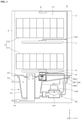
- FIG. 1 is a cross-sectional view showing a dishwasher 1 in one embodiment.
- the dishwasher 1 may include a housing forming an exterior, a wash tub 2 forming a wash space 21 in the housing and configured to accommodate an object to be washed, a door 3 configured to selectively open and close the wash space 21, a sump 4 disposed in a lower portion of the wash tub 2 and configured to store wash water, a storage 5 disposed in the wash tub 2 and configured to accommodate an object to be washed, and spray arms 6, 7, 8 configured to spray wash water toward an object to be washed stored in the storage 5.
- the object to be washed may include a cooking vessel such as a bowl, a dish, a spoon, chopsticks and the like, and other cooking tools.
- the object to be washed may be referred to as a cooking vessel, for example.
- the wash tub 2 may form the wash space 21 configured to accommodate an object to be washed, and the storage 5 and the spray arms 6, 7, 8 may be disposed in the wash space 21.
- the wash tub 2 may have one open surface, and the one open surface may be opened and closed by the door 3.
- the door 3 may be swivably coupled to the housing and may selectively open and close the wash space 21.
- a lower portion of the door 3 may be hinge-coupled to the housing.
- the door 3 may rotate with respect to a hinge to open and close the wash tub 2.
- the storage 5 may be withdrawn out of the dishwasher 1, and the storage 5 withdrawn outward may be supported by the door 3.
- the sump 4 may include a storing part 41 configured to store wash water, a sump cover 42 configured to divide the storing part 41 and the wash tub 2, a water supplier 43 configured to supply water to the storing part 41 from the outside, and a water drain 44 configured to drain water outward from the storing part 41, and a water supply pump 45 and a supply path 46 configured to supply water from the storing part 41 to the spray arms 6, 7, 8.
- the sump cover 42 may be disposed in an upper portion of the sump 4 and may divide the wash tub 2 and the sump 4.
- the sump cover 42 may be provided with a plurality of return holes for returning wash water sprayed to the wash space 21 through the spray arms 6, 7, 8. That is, the wash water sprayed from the spray arms 6, 7, 8 may fall to a lower portion of the wash space 21 and may be returned to the storing part 41 of the sump 4 through the sump cover 42.
- the water supply pump 45 may be disposed in a lateral portion or a lower portion of the storing part 41 and supply wash water to the spray arms 6, 7, 8.
- the water supply pump 45 may connect to the storing part 41 and the other end may connect to the supply path 46.
- the water supply pump 45 may be provided therein with an impeller 451, a motor 453 and the like. When power is supplied to the motor 453, the impeller 451 may rotate, and water in the storing part 41 may be supplied to the spray arms 6, 7, 8 through the supply path 46.
- the supply path 46 may selectively supply wash water supplied by the water supply pump 45 to the spray arms 6, 7, 8.
- the supply path 46 may include a first supply path 461 connected to a lower spray arm 6, a second supply path 463 connected to an upper spray arm 7 and a top nozzle 8, and a supply path diverter valve 465 configured to selectively open and close the supply paths 461, 463, 467.
- the supply path diverter valve 465 may control each of the supply paths 461, 463, 467 such that each of the supply paths 461, 463, 467 is opened consecutively or simultaneously.
- At least one storage 5 for storing an object to be washed may be included in the wash space 21.
- the dishwasher 1 is provided with two storages in FIG. 1 , for example, but not limited. That is, the dishwasher 1 may be provided with a single storage or three or more storages. In this case, the number of spray arms may vary depending on the number of storages.
- the storage 5 may include a lower rack 51 and an upper rack 53 for storing an object to be washed.
- the lower rack 51 may be disposed on the sump 4, and the upper rack 53 may be disposed further upward than the lower rack 51.
- the lower rack 51 and the upper rack 53 may be withdrawn outward through one open surface of the wash tub 2.
- the wash tub 2 may be provided with a rail on an inner circumferential surface thereof, and the racks 51, 53 may be provided with a wheel in lower portions thereof. A user may withdraw the storage 5 outward to store an object to be washed, or to take out the object washed after a wash process.
- the spray arm may be disposed in the wash tub 2 and may spray wash water toward an object to be washed in the storage 5.
- the spray arm may include a lower spray arm 6, an upper spray arm 7, and a top nozzle 8.
- the lower spray arm 6 may be rotatably mounted onto the sump cover 42 and may spray wash water toward an object to be washed storage in the lower rack 51.
- the upper spray arm 7 may be disposed over the lower spray arm 6 and may spray wash water toward an object to be washed storage in the upper rack 53.
- the top nozzle 8 may be disposed in an upper portion of the wash space 21 and may spray wash water to the lower rack 51 and the upper rack 53.
- the first supply path 461 may supply wash water to the lower spray arm 6, and the second supply path 463 may supply wash water to the upper spray arm 7 and the top nozzle 8.
- FIGS. 2 to 8 a structure of the lower spray arm 6 is specifically described with reference to FIGS. 2 to 8 .
- the below-described structure of the lower spray arm 6 may be applied to a structure of the upper spray arm 7 identically or similarly.
- FIG. 2 is an enlarged view showing portion A in FIG. 1 .
- FIG. 3 is a view showing a part of a bottom surface of a spray arm 6 in one embodiment.
- FIG. 4 is a plan view showing a flow path diverter 65 in one embodiment.
- the spray arm 6 may be rotatably disposed in the wash tub, may spray water to an object to be washed, and may be provided with a plurality of spray areas that are separate from each other.
- the spray arm 6 may include a flow path, in which wash water, i.e., water flowing from the second supply path 463 flows, and a spray hole which connects to the flow path and is exposed to an outside of the spray arm 6.
- An area where the flow path and spray hole are disposed is referred to as a spray area in the disclosure.
- the spray area may include a first spray area 61 and a second spray area 62.
- the second spray area 62 may be formed in a way that the second spray area is separate from the first spray area 61. Accordingly, water flowing into the spray arm 6 may flow in the first spray area 61 and the second spray area 62 that are separate from each other, and water flowing in the first spray area 61 and the second spray area 62 may not be mixed.
- the first spray area 61 and the second spray area 62 may be formed into a space in the spray arm 6.
- the first spray area 61 and the second spray area 62 may be formed into spaces in the spray arm 6 as a result of molding manufacturing.
- the first spray area 61 may be formed entirely across the spray arm 6 in a lengthwise direction of the spray arm 6 such that the spray arm 6 rotating sprays water entirely to the cooking vessels storage in the lower rack 51.
- water may flow to the second spray area 62 to wash the left contaminants.
- a mode in which water flows to the first spray area 61 to entirely wash cooking vessels is referred to as an ordinary wash mode
- a mode in which water flows to the second spray area 62 to wash contaminants left on some cooking vessels is referred to as an intensive wash mode.
- the intensive wash mode may differ from the ordinary wash mode in that sprayed water needs to give a great impact on a cooking vessel to wash contaminants that are not washed and firmly attached onto a surface of the cooking vessel.
- At least one of an amount of sprayed water and a spray speed in the second spray area 62 may be greater than that in the first spray area 61.
- an output of the water supply pump 45 may increase in the intensive wash mode in which water is sprayed in the second spray area 62, for example. Additionally, to increase a spray speed of water in the second spray area 62 in a state in which the output of the water supply pump 45 is the same, a total cross-sectional area of spray holes in the second spray area 62 may be less than a total cross-sectional area of spray holes in the first spray area 61, for example.
- the first spray area 61 may be formed entirely across the spray arm 6 in the lengthwise direction thereof.
- the second spray area 62 may be formed partially in the spray arm in the lengthwise direction thereof.
- the flow path diverter 65 may be included in the spray arm 6.
- the flow path diverter 65 may selectively open and close a flow of water to the plurality of spray areas.
- a mounting part 63 onto which the flow path diverter 65 is mounted may be formed at a rotation center of the spray arm 6.
- the flow path diverter 65 may be mounted onto the mounting part 63 of the spray arm 6 and may rotate with respect to the mounting part 63 to allow water to flow to any one of the first spray area 61 and the second spray area 62.
- the mounting part 63 may include a central hole 630, a first connecting hole 631 and a second connecting hole 632.
- the central hole 630 may be formed in a central portion of the mounting part 63, and a coupling projection 650 formed at the flow path diverter 65 may be fitted into the central hole 630.
- the flow path diverter 65 may be coupled to the mounting part 63 using the above structure to rotate with respect to the mounting part 63.
- the first connecting hole 631 may be respectively formed on both sides of the central portion of the mounting part 63 and may connect to the first spray area 61.
- the first connecting hole 631 may be opened by the flow path diverter 65 and the second connecting hole 632 may be closed by the flow path diverter 65, and water flowing to the spray arm 6 through the first supply path 461 may flow to the first spray area 61 through the first connecting hole 631.
- the first spray area 61 may be respectively formed in both end portions of the spray arm 6 with respect to the mounting part 63. Accordingly, the first connecting hole 631 may be disposed respectively on both sides of the central hole 630.
- the second connecting hole 632 may be formed circumferentially at a position spaced from the first connecting hole 631 and connected to the second spray area 62. In the intensive wash mode, the second connecting hole 632 may be opened by the flow path diverter 65 while the first connecting hole 631 may be closed by the flow path diverter 65, and water flowing to the spray arm 6 through the first supply path 461 may flow to the second spray area 62 through the second connecting hole 632.
- the second spray area 62 may be formed in one end portion the spray arm 6. Accordingly, a single second connecting hole 632 may be disposed between a pair of first connecting holes 631 in a circumferential direction of the mounting part 63.
- a first protrusion 633 may be disposed on an outer edge of the mounting part 63. As illustrated in FIG. 3 , the first protrusion 633 may have a predetermined width and may be formed to protrude toward the flow path diverter 65 on the outer edge of the mounting part 63 in a ring shape.
- the first protrusion 633 may guide the flow path diverter 65 such that the flow path diverter 65 is coupled to the mounting part 63.
- the flow path diverter 65 fitted into the mounting part 63 may be guided by the first protrusion 633 and may rotate with respect to the mounting part 63.
- a first wall 641 and a second wall 642 may be formed at the spray arm 6.
- the spray arm 6 may be manufactured to have the first wall 641 and the second wall 642 as a result of molding such that the first wall 641 and the second wall 642 partially block a space formed in the spray arm 6.
- the first wall 641, as illustrated in FIG. 3 may be formed in a way that the first wall 641 separates the pair of first connecting holes 631 and the pair of first spray areas 61.
- the first wall 641 may be formed to separate the pair of first connecting holes 631 at a position where the pair of first connecting holes 631 is circumferentially adjacent to each other, and may be formed from the central hole 630 and to an edge of the spray arm 6 in a transverse direction of the spray arm 6.
- the second wall 642 may separate the first connecting hole 631 and the second connecting hole 632, and separate the first spray area 61 and the second spray area 62.
- the second spray area 62 may be formed respectively in both end portions of the spray arm 6.
- the second wall 642 may include a 2-1 wall (6421), and a 2-2 wall (6422).
- the 2-1 wall 6421 may be formed from the central hole 630 to the edge of the spray arm 6 in the transverse direction thereof to separate the first connecting hole 631 formed at a position eccentric to one end portion of the spray arm 6, in which the first spray area 61 is only formed with respect to the central hole 630, from the second connecting hole 632 formed circumferentially at a position adjacent to the first connecting hole 631.
- the 2-2 wall 6422 may be formed to separate the first connecting hole 631 formed at a position eccentric to the other end portion of the spray arm 6, in which the first spray area 61 and the second spray area 62 are all formed with respect to the central hole 630, from the second connecting hole 632 formed circumferentially at a position adjacent to the first connecting hole 631.
- One end of the 2-2 wall 6422 may be formed up to the central hole 630 and the other end may extend in the lengthwise direction of the spray arm 6.
- the flow path diverter 65 may include a coupling projection 650, a dent part 651 and a closing part 652.
- the flow path diverter 65 may be provided with a hole, to which a rotation shaft of a second actuator 67 is coupled, at a center thereof, and may be rotated with respect to the mounting part 63 of the spray arm 6 by the second actuator 67.
- the coupling projection 650 may have a predetermined width and may be formed in a central portion of the flow path diverter 65 to protrude toward the mounting part 63 at a position corresponding to the central hole 630 of the mounting part 63 in a ring shape.
- the coupling projection 650 may be fitted into the central hole 630 of the mounting part 63, and the flow path diverter 65 may be coupled to the mounting part 63.
- the dent part 651 may be formed in a way that the flow path diverter 65 is partially dent on both sides of the coupling projection 650, and as a result of rotation, may selectively open any one of the first connecting hole 631 and the second connecting hole 632.
- the closing part 652 may be formed as a portion except for the dent part 651 in the flow path diverter 65, and as a result of rotation, may selectively close any one of the first connecting hole 631 and the second connecting hole 632.
- the closing part 652 may overlap the second connecting hole 632. In this case, water introduced into the spray arm 6 may flow to the first spray area 61 through the first connecting hole 631.
- the water introduced into the spray arm 6 may flow to the second spray area 62 through the second connecting hole 632.
- a second protrusion 653 may be disposed on an outer edge of the flow path diverter 65.
- the second protrusion 653 may be formed in a way that the second protrusion 653 having a predetermined width protrudes toward the mounting part 63 along the outer edge of the flow path diverter 65.
- the second protrusion 653 may be fitted into the first protrusion 633 of the mounting part 63, and when the flow path diverter 65 rotates with respect to the mounting part 63, the second protrusion 653 may be guided by the first protrusion 633, and the flow path diverter 65 may rotate without escaping from the mounting part 63.
- the second protrusion 653 may contact a bottom surface of the mounting part 63 to suppress permeation of water passing through the dent part 651 into the flow path diverter 65 through a gap between the mounting part 63 and the flow path diverter 65 and suppress a flow of the water into the connecting hole closed by the closing part 652.
- the second protrusion 653 may suppress a flow of water into the second connecting hole 632 through the gap between the mounting part 63 and the flow path diverter 65. Additionally, the second protrusion 653 may help to reduce a contact surface between the mounting part 63 and the flow path diverter 65, thereby reducing wear on a portion where the mounting part 63 contacts the flow path diverter 65.
- the dishwasher may include a first or spray arm actuator 66 and a second or diverter actuator 67.
- the first actuator 66 may rotate the spray arm 6, and the second actuator 67 may rotate the flow path diverter 65.
- a step motor capable of controlling a rotation angle and a rotation direction precisely may be provided as the first actuator 66 and the second actuator 67, for example.
- the rotation shaft of the second actuator 67 may be coupled to the center of the flow path diverter 65. Accordingly, the flow path diverter 65 may be rotated by the second actuator 67 with respect to the mounting part 63.
- a rotation shaft of the first actuator 66 may be spaced from the rotation center of the spray arm 6.
- a first gear 691 may be coupled to the rotation center of the spray arm 6.
- the spray arm 6 may rotate as a result of rotation of the first gear 691, but the flow path diverter 65 may not be affected by the rotation of the first gear 691.
- a second gear 692 may be coupled to the rotation shaft of the first actuator 66, and the first gear 691 and the second gear 692 may be coupled to each other.
- the spray arm 6 may rotate, as a result of operation of the first actuator 66.
- the rotation shaft of the second actuator 67 may be coupled to a rotation center of the flow path diverter 65 to rotate the flow path diverter 65.
- the flow path diverter 65 may selectively open any one of the first connecting hole 631 and the second connecting hole 632 as a result of rotation of the dent part 651.
- FIG. 5 is a bottom view showing a flow path diverter 65 coupled to a spray arm 6 in a state in which a first spray area 61 is opened while a second spray area 62 is closed.
- FIG. 6 is a bottom view showing a flow path diverter 65 coupled to a spray arm 6 in a state in which a first spray area 61 is closed while a second spray area 62 is opened.
- the dent part 651 of the flow path diverter 65 may overlap a first spray hole 611, and the closing part 652 of the flow path diverter 65 may overlap a second spray hole 621.
- the first spray hole 611 may be opened, and the second spray hole 621 may be closed. Accordingly, water flowing into the spray arm 6 may flow to the first spray area 61 through the first spray hole 611, and the dishwasher may operate in the ordinary wash mode.
- the flow path diverter 65 may be rotated by the second actuator 67 in the state of FIG. 5 , and the dent part 651 may overlap the second spray hole 621, and the closing part 652 may overlap the first spray hole 611.
- the first spray hole 611 may be closed, and the second spray hole 621 may be opened. Accordingly, water flowing into the spray arm 6 may flow to the second spray area 62 through the second spray hole 621, and the dishwasher may operate in the intensive wash mode.
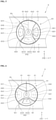
- FIGS. 7 and 8 are plan views schematically showing a spray arm 6.
- the spray arm 6 may be entirely formed into a bar having a length corresponding to a length of the lower rack 51.
- the first spray area 61 may be disposed in both end portions of the spray arm 6 with respect to the rotation center of the spray arm 6.
- the second spray area 62 may be disposed in one end portion of the spray arm 6 in a way that the second spray area is separate from the first spray area 61.
- the second wall 642 may be formed between the first spray area 61 and the second spray area 62, and the first spray area 61 may be separated from the second spray area 62 by the second wall 642.
- a plurality of first spray holes 611, through which water sprays, may be formed in the first spray area 61.
- Each of the first spray holes 611 may be spaced in the lengthwise direction of the spray arm 6.
- water may spray through the first spray holes 611. Since in the ordinary wash mode, the cooking vessels stored in the lower rack 51 are entirely washed, the first spray holes 611 may be formed in a way that the first spray holes are spaced from one another across the spray arm 6 in the lengthwise direction of the spray arm 6 at relatively regular intervals.
- first spray holes 611 formed in both end portions of the spray arm 6 may not necessarily be disposed at symmetrical positions of both end portions, and a distance between the first spray holes 611 may not necessarily be the same.
- second spray holes 621 through which water sprays, may be formed in the second spray area 62.
- water may spray through the second spray hole 621.
- cooking vessels with remaining contaminants, among the cooking vessels stored in the lower rack 51, may be washed.
- the second spray hole 621 may be formed only in a specific area of the spray arm 6, for example.
- the second spray holes 621 may be disposed densely in a specific area of the spray arm 6. Since the second spray holes 621 are densely disposed in a specific area of the spray arm 6, water may intensively spray to a cooking vessel with remaining contaminants, thereby ensuring improvement in washing efficiency.
- the dishwasher may further include a camera 68 disposed on the spray arm 6.
- the camera 68 may detect the position of a cooking vessel with remaining contaminants, among the cooking vessels stored in the lower rack 51, after the ordinary wash mode ends.
- the camera 68 may capture an image, and the captured image may be transmitted to a controller included in the dishwasher.
- the controller may perceive the saturation, brightness, shape and the like of contaminants attached onto a cooking vessel from the transmitted image, and may ascertain the position of the cooking vessel with the remaining contaminants to be washed.
- Any sort of camera may be used as the camera 68 as long as the camera 68 captures an image such that the controller ascertains whether there are remaining contaminants.
- the controller may rotate the spray arm 6 as a result of control over operation of the first actuator 66 such that the second spray hole 621 approaches to a cooking vessel with remaining contaminants.
- the controller may dispose the camera 68 near the cooking vessel with remaining contaminants to accurately ascertain the position of the cooking vessel with remaining contaminants based on an image transmitted from the camera 68. As the camera 68 becomes closer to the cooking vessel with remaining contaminants, the controller may accurately ascertain the position and state of the contaminants from a captured image.
- the second spray area 62 and the second spray hole 621 need to approach the cooking vessel with remaining contaminants.
- the camera 68 and the second spray area 62 may be disposed at the same position of the spray arm 6, for example.
- the camera 68 may be disposed in the second spray area 62.
- the camera 68 and the second spray hole 621 may be disposed at the same position of the spray arm 6, for example.
- the camera 68 may be disposed near the second spray hole 621.
- FIG. 7 is a schematic view showing a spray arm 6 in a state in which a first spray area 61 is opened while a second spray area 62 is closed.
- a coupling between the flow path diverter 65 and the spray arm 6 schematically illustrated in FIG. 7 is the same as that in FIG. 5 .
- Hatched portions in FIGS. 7 and 8 denote a closed flow path.
- water introduced into the spray arm 6 may pass through the first spray hole 611, flow to a pair of first spray areas 61 formed in both end portions of the spray arm 6 and spray through the first spray holes 611.
- operation in the ordinary wash mode may be performed, and during the operation in the ordinary wash mode, the spray arm 6 may rotate as a result of operation of the first actuator 66 to wash cooking vessels stored in the lower rack 51 entirely.
- FIG. 8 is a schematic view showing a spray arm 6 in a state in which a first spray area 61 is closed while a second spray area 62 is opened.
- a coupling between the flow path diverter 65 and the spray arm 6 schematically illustrated in FIG. 8 is the same as that in FIG. 6 .
- water introduced into the spray arm 6 may pass through the second spray hole 621, flow to the second spray area 62 formed in one end portion of the spray arm 6 and spray through the second spray hole 621, as indicated by the arrow.
- operation in the intensive wash mode may be performed, and during the operation in the intensive wash mode, the second spray hole 621 may approach a position, where a cooking vessel with remaining contaminants is placed, as a result of operation of the first actuator 66 to wash the remaining contaminants.
- the spray arm 6 may spray water without rotating at a standstill.
- the spray arm 6 may spray water in a state in which the spray arm 6 makes reciprocating rotations such that the second spray hole 621 makes reciprocating rotations at a position near the contaminants within a range of predetermined angles.
- FIG. 9 is a flow chart showing a control method of a dishwasher in one embodiment.
- the controller included in the dishwasher may connect to the water supply pump 45, the first actuator 66, the second actuator 67, the camera 68 and the like in a communicable manner and may control the same, to perform each step of the control method of the dishwasher in the embodiment.
- the controller may operate the water supply pump 45 to spray water through the first spray area 61 disposed at the spray arm 6 and wash an object to be washed (S110).
- step 110 the dishwasher may operate in the ordinary wash mode.
- the spray arm 6 may rotate, water may spray from the first spray area 61, and cooking vessels stored in the lower rack 51 may be washed entirely.
- the controller may stop the operation of the water supply pump 45 to end step 110.
- the controller may determine whether contaminants are left on the object to be washed from an image captured by the camera 68 disposed at the spray arm 6 (S120).
- the controller may receive an image from the camera 68 disposed at the spray arm 6 in step 110, and when necessary, may rotate the spray arm 6 as a result of operation of the first actuator 66 to receive an image of the cooking vessels stored in the lower rack 51 from the camera 68 after step 110 ends.
- the controller may perceive the saturation, brightness, shape and the like of contaminants attached onto a cooking vessel from the transmitted image to ascertain whether contaminants remain on a cooking vessel and the position of the cooking vessel with the remaining contaminants to be washed.
- the process of washing a cooking vessel may end, and when contaminants remain on the cooking vessel, the next step may be performed.
- the controller may operate the first actuator 66 and allow the second spray hole 621, disposed in the second spray area 62 of the spray arm 6, to approach the contaminants (S130).
- the controller may rotate the spray arm 6 at a predetermined angle as a result of control over the first actuator 66 to allow the second spray hole 621 to approach the contaminants as close as possible.
- the camera 68 since the camera 68 is disposed near the second spray hole 621, the camera 68 may also approach the contaminants.
- the controller may operate the second actuator 67 and divert a flow path of water such that the flow path diverter 65 disposed at the spray arm 6 blocks a flow of the water to the first spray area 61 and allows the water to flow to the second spray area 62 (S140).
- the flow path diverter 65 may close the first connecting hole 631 and open the second connecting hole 632 to prepare for intensive washing for removing remaining contaminants.
- step 130 may be performed before step 140
- step 140 may be performed before step 130 or step 130 and step 140 may be performed at the same time.
- the spray arm 6 may spray water through the second spray hole 621 to wash the cooking vessel with remaining contaminants (S150).
- step 150 water introduced into the spray arm 6 may flow through the second spray area 62 and spray through the second spray hole 621 to intensively wash the cooking vessel with remaining contaminants.
- the spray arm 6 may stop without rotating in step 150 such that the second spray hole 621 stays near the cooking vessel with remaining contaminants, thereby improving the washing efficiency.
- the controller may allow the spray arm 6 to make reciprocating rotations as a result of control over operation of the first actuator 66 such that the second spray hole 621 makes reciprocating rotations near the contaminants within a range of predetermined angles, thereby improving the washing efficiency further.
- the camera 68 may capture an image of a portion with remaining contaminants during the wash process.
- the controller may receive the transmitted image, and when ascertaining the remaining contaminants are removed based on the image, may end step 150.
- the dishwasher may perform step 120 or step 150 to wash the cooking vessel with remaining contaminants in the intensive wash mode.
- the controller may wash each of the cooking vessels in the intensive wash mode consecutively. Since the flow path diverter operates such that water sprays to the second spray area 62 after a first operation in the intensive wash mode ends, step 120, step 130 and step 150 may be performed while step 140 is omitted.
- the spray arm 6 may be provided with the first spray area 61 and the second spray area 62 separately, and may spray water to the first spray area 61 in the ordinary wash mode and spray water to the second spray area 62 in the intensive wash mode to wash an object to be washed, thereby removing contaminants left on a cooking vessel effectively.
- the camera 68 may be disposed in the first spray area of the spray arm 6. Accordingly, the camera 68 may approach a position with remaining contaminants, to ascertain whether there are contaminants, a position where contaminants are present and the like more accurately through the camera 68.
- Dishwasher 642 Second wall 2: Wash tub 6421: 2-1 wall 3: Door 6422: 2-2 wall 4: Sump 65: Flow path diverter 45: Water supply pump 650: Coupling projection 5: Storage 651: Dent part 51: Lower rack 652: Closing part 6: Spray arm 653: Second protrusion 61: First spray area 66: First actuator 611: First spray hole 67: Second actuator 62: Second spray area 68: Camera 621: Second spray hole 691: First gear 63: Mounting part 692: Second gear 630: Central hole 631: First connecting hole 632: Second connecting hole 633: First protrusion 641: First wall
Landscapes
- Engineering & Computer Science (AREA)
- Water Supply & Treatment (AREA)
- Washing And Drying Of Tableware (AREA)
Abstract
Description
- Disclosed herein are a dishwasher and a control method thereof having a structure that ensures improvement in washing performance.
- Details in the background section do not constitute the related art but are given only as background information concerning the subject matter of the present disclosure.
- Dishwashers are devices that spray water to an object to be washed such as a cooking vessel, a cooking tool and the like, stored in the dishwasher, to wash the object to be washed. The water used for a wash can include detergent.
- The dishwasher is ordinarily comprised of a wash tub forming a wash space, a storage disposed in the wash tub and configured to accommodate an object to be washed, a spray arm configured to spray water to the storage, and a sump configured to store water and to supply water to the spray arm.
- The dishwashers can help users to reduce time and efforts spent on washing the dishes after a meal, thereby improving user convenience.
- When the dishwashers are used to wash objects to be washed, contaminants can remain on some of the objects to be washed, even after a wash process in which water sprays ends.
- In this case, the users ascertain a cooking vessel with the remaining contaminants, and secondarily wash the cooking vessel to remove the remaining contaminants from the cooking vessel.
- The secondary wash causes additional work to users since the users need to spend additional time and efforts on the secondary wash, thereby making the users reluctant to purchase and use the dishwashers. Thus, there is a growing need for a dishwasher that can help to reduce the burden of the secondary wash.
- It is an object of the present invention to provide a dishwasher having a structure that may help to ascertain an object to be washed with remaining contaminants after a process of washing objects to be washed ends, and to perform an additional process of removing the remaining contaminants.
- It is an object of the present invention to provide a dishwasher that may be provided with a means of ascertaining remaining contaminants.
- It is an object of the present invention to provide a control method of a dishwasher that may remove remaining contaminants effectively.
- Aspects according to the present disclosure are not limited to the above ones, and other aspects and advantages that are not mentioned above can be clearly understood from the following description and can be more clearly understood from the embodiments set forth herein. Additionally, the aspects and advantages in the present disclosure can be realized via means and combinations thereof that are described in the appended claims.
- The object of the present invention is solved by the features of the independent claims. Preferred embodiments are given in the dependent claims.
- A dishwasher in one embodiment may be provided with a spray arm, and the spray arm may be provided separately with areas configured to spray water to a first spray area and a second spray area, and may spray water to the first spray area to entirely wash objects to be washed stored in the dishwasher and may spray water to the second spray area to wash objects to be washed with remaining contaminants by applying a great impact on the object to be washed with remaining contaminants.
- The dishwasher in one embodiment may be provided with a camera that is disposed at the spray arm and ascertains an object to be washed with remaining contaminants.
- A control method of a dishwasher in one embodiment may include operating in an ordinary wash mode to entirely wash objects to be washed stored in the dishwasher and then operating in an intensive wash mode to intensively wash the ascertained object to be washed with remaining contaminants.
- A dishwasher in one embodiment may include a wash tub configured to accommodate an object to be washed, a spray arm rotatably disposed in the wash tub, configured to spray water to an object to be washed and provided with a plurality of spray areas that are separate from each other, a flow path diverter disposed at the spray arm and configured to selectively open and close a flow of water to the plurality of spray areas, a diverter actuator configured to rotate the flow path diverter, wherein the spray areas include a first spray area, and a second spray area being separate from the first spray area and having at least one of an amount of sprayed water or a spray speed greater than that of the first spray area.
- The spray arm may be provided with a mounting part, onto which the flow path diverter is mounted.
- The mounting part may be provided at a rotation center of the spray arm.
- The mounting part may be provided with a central hole which is formed in a central portion of the mounting part and to which a coupling projection formed at the flow path diverter is fitted.
- The mounting part may be provided with a first connecting hole formed on one or both sides of the central portion and connected to the first spray area.
- The mounting part may be provided with a second connecting hole spaced circumferentially from the first connecting hole and connected to the second spray area.
- The spray arm may include a first wall configured to separate the first connecting hole from other area of the spray arm.
- The spray arm may include a second wall configured to separate the first connecting hole and the second connecting hole and to separate the first spray area and the second spray area.
- The flow path diverter may include the coupling projection protruding toward the mounting part in a ring shape at a position corresponding to the central hole of the mounting part in a central portion of the flow path diverter, a dent part formed in a way that the flow path diverter is partially dent on both sides of the coupling projection and configured to selectively open any one of the first connecting hole and the second connecting hole as a result of rotation, and a closing part formed as a portion of the flow path diverter except for the dent part, and configured to selectively close any one of the first connecting hole and the second connecting hole as a result of rotation.
- In the dishwasher of one embodiment, the mounting part may be provided with a first protrusion, which is configured to guide the flow path diverter such that the flow path diverter is coupled to the mounting part and protrudes toward the flow path diverter in a ring shape, on an outer edge thereof.
- The flow path diverter may be provided with a second protrusion, which has a predetermined width and protrudes toward the mounting part along an outer edge of the flow path diverter, on the outer edge thereof.
- A rotation shaft of the diverter actuator (second actuator) may be coupled to a rotation center of the flow path diverter such that the diverter actuator rotates the flow path diverter.
- The flow path diverter may selectively open any one of the first connecting hole and the second connecting hole as a result of rotation of the dent part.
- A rotation shaft of the spray arm actuator (first actuator) may be spaced from the rotation center of the spray arm.
- A first gear may be coupled to the rotation center of the spray arm.
- A second gear may be coupled to the rotation shaft of the spray arm actuator.
- The first gear and the second gear may be coupled to each other.
- In the dishwasher of one embodiment, a camera may be disposed.
- The camera may be disposed in the second spray area.
- The spray arm may be formed into a bar or may have bar shape.
- The first spray area may be disposed in one or both end portions of the spray arm with respect to the rotation center of the spray arm.
- The second spray area may be disposed in one end portion of the spray arm in a way that the second spray area is separate from the first spray area.
- One or more first spray holes through which water is sprayed during operation may be formed in the first spray area.
- At least one second spray holes through which water is sprayed during operation may be formed in the second spray area.
- The first spray holes may be disposed in a lengthwise direction of the spray arm at intervals.
- When a plurality of second spray holes are provided, the second spray holes may be densely disposed in a specific area of the spray arm, in particular in the second spray area further specifically close to the camera.
- At least one of second spray holes through which water may be sprayed may be formed in the second spray area.
- The camera may be disposed near the second spray hole.
- A control method of a dishwasher in one embodiment may include washing an object to be washed by spraying water through a first spray area included in a spray arm, determining whether contaminants remain on the object to be washed based on an image captured by a camera disposed at the spray arm, allowing a second spray hole disposed in a second spray area of the spray arm to approach the contaminants, as a result of operation of a spray arm actuator, diverting a flow path of water such that a flow path diverter disposed at the spray arm blocks a flow of water to the first spray area and the water flows to the second spray area, as a result of operation of a diverter actuator, and washing a portion with the remaining contaminants by spraying water through the second spray hole.
- In the control method of one embodiment, washing a portion with the remaining contaminants may include allowing the spray arm to make reciprocating rotations such that the second spray hole makes reciprocating rotations in a range of predetermined angles at a position near the contaminants.
- According to the present disclosure, a spray arm may be provided with a first spray area and a second spray area separately, and may spray water to the first spray area in an ordinary wash mode and spray water to the second spray area in an intensive wash mode to wash an object to be washed, thereby effectively removing contaminants remaining on a cooking vessel.
- According to the present disclosure, a camera may be disposed in the first spray area of the spray arm, and the camera may approach a position where contaminants remain and may ascertain whether there are contaminants and a position where contaminants are present and the like more accurately.
- According to the present disclosure, the spray arm may make reciprocating rotations such that a second spray hole makes reciprocating rotations in a range of predetermined angles at a position close to contaminants in the intensive wash mode, thereby ensuring improvement in washing efficiency.
- Specific effects are described along with the above-described effects in the section of Detailed Description.
- The accompanying drawings constitute a part of the specification, illustrate one or more embodiments in the disclosure, and together with the specification, explain the disclosure, wherein:
-
FIG. 1 is a cross-sectional view showing a dishwasher in one embodiment; -
FIG. 2 is an enlarged view showing portion A inFIG. 1 ; -
FIG. 3 is a view showing a part of a bottom surface of a spray arm in one embodiment; -
FIG. 4 is a plan view showing a flow path diverter in one embodiment; -
FIG.5 is a bottom view showing a flow path diverter coupled to a spray arm in a state in which a first spray area is opened while a second spray area is closed; -
FIG. 6 is a bottom view showing a flow path diverter coupled to a spray arm in a state in which a first spray area is closed while a second spray area is opened; -
FIG. 7 is a schematic view showing a spray arm in a state in which a first spray area is opened while a second spray area is closed; -
FIG. 8 is a schematic view showing a spray arm in a state in which a first spray area is closed while a second spray area is opened; and -
FIG. 9 is a flow chart showing a control method of a dishwasher in one embodiment. - The above-described aspects, features and advantages are specifically described hereunder with reference to the accompanying drawings such that one having ordinary skill in the art to which the present disclosure pertains can easily implement the technical idea of the disclosure. In the disclosure, detailed description of known technologies in relation to the disclosure is omitted if it is deemed to make the gist of the disclosure unnecessarily vague. Below, preferred embodiments according to the disclosure are specifically described with reference to the accompanying drawings. In the drawings, identical reference numerals can denote identical or similar components.
- The terms "first", "second" and the like are used herein only to distinguish one component from another component. Thus, the components should not be limited by the terms. Certainly, a first component can be a second component unless stated to the contrary.
- Throughout the disclosure, each component can be provided as a single one or a plurality of ones, unless explicitly stated to the contrary.
- The singular forms "a", "an" and "the" are intended to include the plural forms as well, unless explicitly indicated otherwise. It should be further understood that the terms "comprise" or "include" and the like, set forth herein, are not interpreted as necessarily including all the stated components or steps but can be interpreted as excluding some of the stated components or steps or can be interpreted as including additional components or steps.
- Throughout the disclosure, the terms "A and/or B" as used herein can denote A, B or A and B, and the terms "C to D" can denote C or greater and D or less, unless stated to the contrary.
- In the drawings, a direction, in which components are disposed, is indicated using a rectangular coordinate system (x, y, z).
-
FIG. 1 is a cross-sectional view showing adishwasher 1 in one embodiment. Referring toFIG. 1 , thedishwasher 1 may include a housing forming an exterior, awash tub 2 forming awash space 21 in the housing and configured to accommodate an object to be washed, adoor 3 configured to selectively open and close thewash space 21, asump 4 disposed in a lower portion of thewash tub 2 and configured to store wash water, a storage 5 disposed in thewash tub 2 and configured to accommodate an object to be washed, andspray arms - The
wash tub 2 may form thewash space 21 configured to accommodate an object to be washed, and the storage 5 and thespray arms wash space 21. Thewash tub 2 may have one open surface, and the one open surface may be opened and closed by thedoor 3. - The
door 3 may be swivably coupled to the housing and may selectively open and close thewash space 21. For example, a lower portion of thedoor 3 may be hinge-coupled to the housing. In this case, thedoor 3 may rotate with respect to a hinge to open and close thewash tub 2. As a result of the opening of thedoor 3, the storage 5 may be withdrawn out of thedishwasher 1, and the storage 5 withdrawn outward may be supported by thedoor 3. - The
sump 4 may include a storingpart 41 configured to store wash water, asump cover 42 configured to divide the storingpart 41 and thewash tub 2, awater supplier 43 configured to supply water to the storingpart 41 from the outside, and awater drain 44 configured to drain water outward from the storingpart 41, and awater supply pump 45 and asupply path 46 configured to supply water from the storingpart 41 to thespray arms - The
sump cover 42 may be disposed in an upper portion of thesump 4 and may divide thewash tub 2 and thesump 4. Thesump cover 42 may be provided with a plurality of return holes for returning wash water sprayed to thewash space 21 through thespray arms spray arms wash space 21 and may be returned to the storingpart 41 of thesump 4 through thesump cover 42. - The
water supply pump 45 may be disposed in a lateral portion or a lower portion of the storingpart 41 and supply wash water to thespray arms - One end of the
water supply pump 45 may connect to the storingpart 41 and the other end may connect to thesupply path 46. Thewater supply pump 45 may be provided therein with animpeller 451, amotor 453 and the like. When power is supplied to themotor 453, theimpeller 451 may rotate, and water in the storingpart 41 may be supplied to thespray arms supply path 46. - The
supply path 46 may selectively supply wash water supplied by thewater supply pump 45 to thespray arms - The
supply path 46 may include afirst supply path 461 connected to alower spray arm 6, asecond supply path 463 connected to anupper spray arm 7 and atop nozzle 8, and a supply path divertervalve 465 configured to selectively open and close thesupply paths valve 465 may control each of thesupply paths supply paths - Additionally, at least one storage 5 for storing an object to be washed may be included in the
wash space 21. Thedishwasher 1 is provided with two storages inFIG. 1 , for example, but not limited. That is, thedishwasher 1 may be provided with a single storage or three or more storages. In this case, the number of spray arms may vary depending on the number of storages. - The storage 5 may include a lower rack 51 and an
upper rack 53 for storing an object to be washed. The lower rack 51 may be disposed on thesump 4, and theupper rack 53 may be disposed further upward than the lower rack 51. The lower rack 51 and theupper rack 53 may be withdrawn outward through one open surface of thewash tub 2. To this end, thewash tub 2 may be provided with a rail on an inner circumferential surface thereof, and theracks 51, 53 may be provided with a wheel in lower portions thereof. A user may withdraw the storage 5 outward to store an object to be washed, or to take out the object washed after a wash process. - The spray arm may be disposed in the
wash tub 2 and may spray wash water toward an object to be washed in the storage 5. - The spray arm may include a
lower spray arm 6, anupper spray arm 7, and atop nozzle 8. Thelower spray arm 6 may be rotatably mounted onto thesump cover 42 and may spray wash water toward an object to be washed storage in the lower rack 51. - The
upper spray arm 7 may be disposed over thelower spray arm 6 and may spray wash water toward an object to be washed storage in theupper rack 53. Thetop nozzle 8 may be disposed in an upper portion of thewash space 21 and may spray wash water to the lower rack 51 and theupper rack 53. - As described above, the
first supply path 461 may supply wash water to thelower spray arm 6, and thesecond supply path 463 may supply wash water to theupper spray arm 7 and thetop nozzle 8. - Hereunder, a structure of the
lower spray arm 6 is specifically described with reference toFIGS. 2 to 8 . The below-described structure of thelower spray arm 6 may be applied to a structure of theupper spray arm 7 identically or similarly. -
FIG. 2 is an enlarged view showing portion A inFIG. 1 .FIG. 3 is a view showing a part of a bottom surface of aspray arm 6 in one embodiment.FIG. 4 is a plan view showing a flow path diverter 65 in one embodiment. - The
spray arm 6 may be rotatably disposed in the wash tub, may spray water to an object to be washed, and may be provided with a plurality of spray areas that are separate from each other. - The
spray arm 6 may include a flow path, in which wash water, i.e., water flowing from thesecond supply path 463 flows, and a spray hole which connects to the flow path and is exposed to an outside of thespray arm 6. An area where the flow path and spray hole are disposed is referred to as a spray area in the disclosure. - As illustrated in
FIG. 3 , the spray area may include afirst spray area 61 and asecond spray area 62. Thesecond spray area 62 may be formed in a way that the second spray area is separate from thefirst spray area 61. Accordingly, water flowing into thespray arm 6 may flow in thefirst spray area 61 and thesecond spray area 62 that are separate from each other, and water flowing in thefirst spray area 61 and thesecond spray area 62 may not be mixed. - The
first spray area 61 and thesecond spray area 62 may be formed into a space in thespray arm 6. For example, thefirst spray area 61 and thesecond spray area 62 may be formed into spaces in thespray arm 6 as a result of molding manufacturing. - When cooking vessels storage in the lower rack 51 are entirely washed at the same time during a process of washing the cooking vessels, water may flow to the
first spray area 61 to wash the cooking vessels entirely. To this end, thefirst spray area 61 may be formed entirely across thespray arm 6 in a lengthwise direction of thespray arm 6 such that thespray arm 6 rotating sprays water entirely to the cooking vessels storage in the lower rack 51. - When contaminants are left on a cooking vessel disposed at a specific position of the lower rack 51 after the cooking vessels are entirely washed at the same time, water may flow to the
second spray area 62 to wash the left contaminants. - Hereunder, a mode in which water flows to the
first spray area 61 to entirely wash cooking vessels is referred to as an ordinary wash mode, and a mode in which water flows to thesecond spray area 62 to wash contaminants left on some cooking vessels is referred to as an intensive wash mode. - The intensive wash mode may differ from the ordinary wash mode in that sprayed water needs to give a great impact on a cooking vessel to wash contaminants that are not washed and firmly attached onto a surface of the cooking vessel.
- To this end, at least one of an amount of sprayed water and a spray speed in the
second spray area 62 may be greater than that in thefirst spray area 61. - To increase an amount of sprayed water in the
second spray area 62, an output of thewater supply pump 45 may increase in the intensive wash mode in which water is sprayed in thesecond spray area 62, for example. Additionally, to increase a spray speed of water in thesecond spray area 62 in a state in which the output of thewater supply pump 45 is the same, a total cross-sectional area of spray holes in thesecond spray area 62 may be less than a total cross-sectional area of spray holes in thefirst spray area 61, for example. - Since the coking vessels storage in the lower rack 51 are entirely washed in the ordinary wash mode, the
first spray area 61 may be formed entirely across thespray arm 6 in the lengthwise direction thereof. In the intensive wash mode, some cooking vessels storage in the lower rack 51 are washed. Accordingly, thesecond spray area 62 may be formed partially in the spray arm in the lengthwise direction thereof. - The flow path diverter 65 may be included in the
spray arm 6. - The flow path diverter 65 may selectively open and close a flow of water to the plurality of spray areas. A mounting
part 63 onto which the flow path diverter 65 is mounted may be formed at a rotation center of thespray arm 6. - The flow path diverter 65 may be mounted onto the mounting
part 63 of thespray arm 6 and may rotate with respect to the mountingpart 63 to allow water to flow to any one of thefirst spray area 61 and thesecond spray area 62. - As illustrated in
FIG. 3 , the mountingpart 63 may include acentral hole 630, a first connectinghole 631 and a second connectinghole 632. - The
central hole 630 may be formed in a central portion of the mountingpart 63, and acoupling projection 650 formed at the flow path diverter 65 may be fitted into thecentral hole 630. The flow path diverter 65 may be coupled to the mountingpart 63 using the above structure to rotate with respect to the mountingpart 63. - The first connecting
hole 631 may be respectively formed on both sides of the central portion of the mountingpart 63 and may connect to thefirst spray area 61. In the ordinary wash mode, the first connectinghole 631 may be opened by the flow path diverter 65 and the second connectinghole 632 may be closed by the flow path diverter 65, and water flowing to thespray arm 6 through thefirst supply path 461 may flow to thefirst spray area 61 through the first connectinghole 631. - The
first spray area 61 may be respectively formed in both end portions of thespray arm 6 with respect to the mountingpart 63. Accordingly, the first connectinghole 631 may be disposed respectively on both sides of thecentral hole 630. - The second connecting
hole 632 may be formed circumferentially at a position spaced from the first connectinghole 631 and connected to thesecond spray area 62. In the intensive wash mode, the second connectinghole 632 may be opened by the flow path diverter 65 while the first connectinghole 631 may be closed by the flow path diverter 65, and water flowing to thespray arm 6 through thefirst supply path 461 may flow to thesecond spray area 62 through the second connectinghole 632. - The
second spray area 62 may be formed in one end portion thespray arm 6. Accordingly, a single second connectinghole 632 may be disposed between a pair of first connectingholes 631 in a circumferential direction of the mountingpart 63. - A
first protrusion 633 may be disposed on an outer edge of the mountingpart 63. As illustrated inFIG. 3 , thefirst protrusion 633 may have a predetermined width and may be formed to protrude toward the flow path diverter 65 on the outer edge of the mountingpart 63 in a ring shape. - The
first protrusion 633 may guide the flow path diverter 65 such that the flow path diverter 65 is coupled to the mountingpart 63. In this case, the flow path diverter 65 fitted into the mountingpart 63 may be guided by thefirst protrusion 633 and may rotate with respect to the mountingpart 63. - A
first wall 641 and asecond wall 642 may be formed at thespray arm 6. Thespray arm 6 may be manufactured to have thefirst wall 641 and thesecond wall 642 as a result of molding such that thefirst wall 641 and thesecond wall 642 partially block a space formed in thespray arm 6. - The
first wall 641, as illustrated inFIG. 3 , may be formed in a way that thefirst wall 641 separates the pair of first connectingholes 631 and the pair offirst spray areas 61. For example, thefirst wall 641 may be formed to separate the pair of first connectingholes 631 at a position where the pair of first connectingholes 631 is circumferentially adjacent to each other, and may be formed from thecentral hole 630 and to an edge of thespray arm 6 in a transverse direction of thespray arm 6. - The
second wall 642, as illustrated inFIG. 3 , may separate the first connectinghole 631 and the second connectinghole 632, and separate thefirst spray area 61 and thesecond spray area 62. Thesecond spray area 62 may be formed respectively in both end portions of thespray arm 6. Accordingly, thesecond wall 642 may include a 2-1 wall (6421), and a 2-2 wall (6422). - The 2-1
wall 6421 may be formed from thecentral hole 630 to the edge of thespray arm 6 in the transverse direction thereof to separate the first connectinghole 631 formed at a position eccentric to one end portion of thespray arm 6, in which thefirst spray area 61 is only formed with respect to thecentral hole 630, from the second connectinghole 632 formed circumferentially at a position adjacent to the first connectinghole 631. - The 2-2
wall 6422 may be formed to separate the first connectinghole 631 formed at a position eccentric to the other end portion of thespray arm 6, in which thefirst spray area 61 and thesecond spray area 62 are all formed with respect to thecentral hole 630, from the second connectinghole 632 formed circumferentially at a position adjacent to the first connectinghole 631. - One end of the 2-2
wall 6422 may be formed up to thecentral hole 630 and the other end may extend in the lengthwise direction of thespray arm 6. - The flow path diverter 65, as illustrated in
FIG. 4 , may include acoupling projection 650, adent part 651 and aclosing part 652. The flow path diverter 65 may be provided with a hole, to which a rotation shaft of asecond actuator 67 is coupled, at a center thereof, and may be rotated with respect to the mountingpart 63 of thespray arm 6 by thesecond actuator 67. - The
coupling projection 650 may have a predetermined width and may be formed in a central portion of the flow path diverter 65 to protrude toward the mountingpart 63 at a position corresponding to thecentral hole 630 of the mountingpart 63 in a ring shape. Thecoupling projection 650 may be fitted into thecentral hole 630 of the mountingpart 63, and the flow path diverter 65 may be coupled to the mountingpart 63. - The
dent part 651 may be formed in a way that the flow path diverter 65 is partially dent on both sides of thecoupling projection 650, and as a result of rotation, may selectively open any one of the first connectinghole 631 and the second connectinghole 632. - The
closing part 652 may be formed as a portion except for thedent part 651 in the flow path diverter 65, and as a result of rotation, may selectively close any one of the first connectinghole 631 and the second connectinghole 632. - When the
dent part 651 overlaps the first connectinghole 631, theclosing part 652 may overlap the second connectinghole 632. In this case, water introduced into thespray arm 6 may flow to thefirst spray area 61 through the first connectinghole 631. - When the
dent part 651 overlaps the second connectinghole 632 and theclosing part 652 overlaps the first connectinghole 631 as a result of the rotation of the flow path diverter 65, the water introduced into thespray arm 6 may flow to thesecond spray area 62 through the second connectinghole 632. - A
second protrusion 653 may be disposed on an outer edge of the flow path diverter 65. Thesecond protrusion 653 may be formed in a way that thesecond protrusion 653 having a predetermined width protrudes toward the mountingpart 63 along the outer edge of the flow path diverter 65. - The
second protrusion 653 may be fitted into thefirst protrusion 633 of the mountingpart 63, and when the flow path diverter 65 rotates with respect to the mountingpart 63, thesecond protrusion 653 may be guided by thefirst protrusion 633, and the flow path diverter 65 may rotate without escaping from the mountingpart 63. - The
second protrusion 653 may contact a bottom surface of the mountingpart 63 to suppress permeation of water passing through thedent part 651 into the flow path diverter 65 through a gap between the mountingpart 63 and the flow path diverter 65 and suppress a flow of the water into the connecting hole closed by theclosing part 652. - For example, when the first connecting
hole 631 is opened and the second connectinghole 632 is closed by the flow path diverter 65, thesecond protrusion 653 may suppress a flow of water into the second connectinghole 632 through the gap between the mountingpart 63 and the flow path diverter 65. Additionally, thesecond protrusion 653 may help to reduce a contact surface between the mountingpart 63 and the flow path diverter 65, thereby reducing wear on a portion where the mountingpart 63 contacts the flow path diverter 65. - As illustrated in
FIG. 2 , the dishwasher may include a first orspray arm actuator 66 and a second ordiverter actuator 67. Thefirst actuator 66 may rotate thespray arm 6, and thesecond actuator 67 may rotate the flow path diverter 65. - A step motor capable of controlling a rotation angle and a rotation direction precisely may be provided as the
first actuator 66 and thesecond actuator 67, for example. - The rotation shaft of the
second actuator 67 may be coupled to the center of the flow path diverter 65. Accordingly, the flow path diverter 65 may be rotated by thesecond actuator 67 with respect to the mountingpart 63. - To prevent the
first actuator 66 from interfering with the rotation of thesecond actuator 67, a rotation shaft of thefirst actuator 66 may be spaced from the rotation center of thespray arm 6. - A
first gear 691 may be coupled to the rotation center of thespray arm 6. Thespray arm 6 may rotate as a result of rotation of thefirst gear 691, but the flow path diverter 65 may not be affected by the rotation of thefirst gear 691. - A
second gear 692 may be coupled to the rotation shaft of thefirst actuator 66, and thefirst gear 691 and thesecond gear 692 may be coupled to each other. In the structure, thespray arm 6 may rotate, as a result of operation of thefirst actuator 66. - The rotation shaft of the
second actuator 67 may be coupled to a rotation center of the flow path diverter 65 to rotate the flow path diverter 65. The flow path diverter 65 may selectively open any one of the first connectinghole 631 and the second connectinghole 632 as a result of rotation of thedent part 651. -
FIG. 5 is a bottom view showing a flow path diverter 65 coupled to aspray arm 6 in a state in which afirst spray area 61 is opened while asecond spray area 62 is closed.FIG. 6 is a bottom view showing a flow path diverter 65 coupled to aspray arm 6 in a state in which afirst spray area 61 is closed while asecond spray area 62 is opened. - As illustrated in
FIG. 5 , thedent part 651 of the flow path diverter 65 may overlap afirst spray hole 611, and theclosing part 652 of the flow path diverter 65 may overlap asecond spray hole 621. In this case, thefirst spray hole 611 may be opened, and thesecond spray hole 621 may be closed. Accordingly, water flowing into thespray arm 6 may flow to thefirst spray area 61 through thefirst spray hole 611, and the dishwasher may operate in the ordinary wash mode. - As illustrated in
FIG. 6 , the flow path diverter 65 may be rotated by thesecond actuator 67 in the state ofFIG. 5 , and thedent part 651 may overlap thesecond spray hole 621, and theclosing part 652 may overlap thefirst spray hole 611. In this case, thefirst spray hole 611 may be closed, and thesecond spray hole 621 may be opened. Accordingly, water flowing into thespray arm 6 may flow to thesecond spray area 62 through thesecond spray hole 621, and the dishwasher may operate in the intensive wash mode. -
FIGS. 7 and 8 are plan views schematically showing aspray arm 6. Thespray arm 6 may be entirely formed into a bar having a length corresponding to a length of the lower rack 51. - The
first spray area 61 may be disposed in both end portions of thespray arm 6 with respect to the rotation center of thespray arm 6. Thesecond spray area 62 may be disposed in one end portion of thespray arm 6 in a way that the second spray area is separate from thefirst spray area 61. In this case, thesecond wall 642 may be formed between thefirst spray area 61 and thesecond spray area 62, and thefirst spray area 61 may be separated from thesecond spray area 62 by thesecond wall 642. - A plurality of first spray holes 611, through which water sprays, may be formed in the
first spray area 61. Each of the first spray holes 611 may be spaced in the lengthwise direction of thespray arm 6. - In the ordinary wash mode, water may spray through the first spray holes 611. Since in the ordinary wash mode, the cooking vessels stored in the lower rack 51 are entirely washed, the first spray holes 611 may be formed in a way that the first spray holes are spaced from one another across the
spray arm 6 in the lengthwise direction of thespray arm 6 at relatively regular intervals. - However, the first spray holes 611 formed in both end portions of the
spray arm 6 may not necessarily be disposed at symmetrical positions of both end portions, and a distance between the first spray holes 611 may not necessarily be the same. - Additionally, at least one of second spray holes 621, through which water sprays, may be formed in the
second spray area 62. In the intensive wash mode, water may spray through thesecond spray hole 621. In the intensive wash mode, cooking vessels with remaining contaminants, among the cooking vessels stored in the lower rack 51, may be washed. - That is, in the intensive wash mode, water may spray only toward a specific position of the lower rack 51 on which the cooking vessels with remaining contaminants are placed. Thus, the
second spray hole 621 may be formed only in a specific area of thespray arm 6, for example. - When a plurality of second spray holes 621 are provided, the second spray holes 621 may be disposed densely in a specific area of the
spray arm 6. Since the second spray holes 621 are densely disposed in a specific area of thespray arm 6, water may intensively spray to a cooking vessel with remaining contaminants, thereby ensuring improvement in washing efficiency. - The dishwasher may further include a
camera 68 disposed on thespray arm 6. Thecamera 68 may detect the position of a cooking vessel with remaining contaminants, among the cooking vessels stored in the lower rack 51, after the ordinary wash mode ends. - The
camera 68 may capture an image, and the captured image may be transmitted to a controller included in the dishwasher. The controller may perceive the saturation, brightness, shape and the like of contaminants attached onto a cooking vessel from the transmitted image, and may ascertain the position of the cooking vessel with the remaining contaminants to be washed. - Any sort of camera may be used as the
camera 68 as long as thecamera 68 captures an image such that the controller ascertains whether there are remaining contaminants. - In the intensive wash mode, the controller may rotate the
spray arm 6 as a result of control over operation of thefirst actuator 66 such that thesecond spray hole 621 approaches to a cooking vessel with remaining contaminants. In this case, the controller may dispose thecamera 68 near the cooking vessel with remaining contaminants to accurately ascertain the position of the cooking vessel with remaining contaminants based on an image transmitted from thecamera 68. As thecamera 68 becomes closer to the cooking vessel with remaining contaminants, the controller may accurately ascertain the position and state of the contaminants from a captured image. - Additionally, to improve washing efficiency in the intensive wash mode, the
second spray area 62 and thesecond spray hole 621 need to approach the cooking vessel with remaining contaminants. For the above-mentioned reasons, thecamera 68 and thesecond spray area 62 may be disposed at the same position of thespray arm 6, for example. - Accordingly, the
camera 68 may be disposed in thesecond spray area 62. - Further, for the above reasons, the
camera 68 and thesecond spray hole 621 may be disposed at the same position of thespray arm 6, for example. Thus, thecamera 68 may be disposed near thesecond spray hole 621. -
FIG. 7 is a schematic view showing aspray arm 6 in a state in which afirst spray area 61 is opened while asecond spray area 62 is closed. A coupling between the flow path diverter 65 and thespray arm 6 schematically illustrated inFIG. 7 is the same as that inFIG. 5 . - Hatched portions in
FIGS. 7 and 8 denote a closed flow path. - In a state of
FIG. 7 , water introduced into thespray arm 6 may pass through thefirst spray hole 611, flow to a pair offirst spray areas 61 formed in both end portions of thespray arm 6 and spray through the first spray holes 611. - In the state of
FIG. 7 , operation in the ordinary wash mode may be performed, and during the operation in the ordinary wash mode, thespray arm 6 may rotate as a result of operation of thefirst actuator 66 to wash cooking vessels stored in the lower rack 51 entirely. -
FIG. 8 is a schematic view showing aspray arm 6 in a state in which afirst spray area 61 is closed while asecond spray area 62 is opened. A coupling between the flow path diverter 65 and thespray arm 6 schematically illustrated inFIG. 8 is the same as that inFIG. 6 . - In a state of
FIG. 8 , water introduced into thespray arm 6 may pass through thesecond spray hole 621, flow to thesecond spray area 62 formed in one end portion of thespray arm 6 and spray through thesecond spray hole 621, as indicated by the arrow. - In the state of
FIG. 8 , operation in the intensive wash mode may be performed, and during the operation in the intensive wash mode, thesecond spray hole 621 may approach a position, where a cooking vessel with remaining contaminants is placed, as a result of operation of thefirst actuator 66 to wash the remaining contaminants. - In the intensive wash mode, the
spray arm 6 may spray water without rotating at a standstill. Alternatively, to improve the washing efficiency, thespray arm 6 may spray water in a state in which thespray arm 6 makes reciprocating rotations such that thesecond spray hole 621 makes reciprocating rotations at a position near the contaminants within a range of predetermined angles. -
FIG. 9 is a flow chart showing a control method of a dishwasher in one embodiment. The controller included in the dishwasher may connect to thewater supply pump 45, thefirst actuator 66, thesecond actuator 67, thecamera 68 and the like in a communicable manner and may control the same, to perform each step of the control method of the dishwasher in the embodiment. - The controller may operate the
water supply pump 45 to spray water through thefirst spray area 61 disposed at thespray arm 6 and wash an object to be washed (S110). - In step 110 (S110), the dishwasher may operate in the ordinary wash mode. In this case, the
spray arm 6 may rotate, water may spray from thefirst spray area 61, and cooking vessels stored in the lower rack 51 may be washed entirely. The controller may stop the operation of thewater supply pump 45 to end step 110. - After step 110 ends, the controller may determine whether contaminants are left on the object to be washed from an image captured by the
camera 68 disposed at the spray arm 6 (S120). - The controller may receive an image from the
camera 68 disposed at thespray arm 6 in step 110, and when necessary, may rotate thespray arm 6 as a result of operation of thefirst actuator 66 to receive an image of the cooking vessels stored in the lower rack 51 from thecamera 68 after step 110 ends. - The controller may perceive the saturation, brightness, shape and the like of contaminants attached onto a cooking vessel from the transmitted image to ascertain whether contaminants remain on a cooking vessel and the position of the cooking vessel with the remaining contaminants to be washed.
- When no contaminants remain on the cooking vessel, the process of washing a cooking vessel may end, and when contaminants remain on the cooking vessel, the next step may be performed.
- The controller may operate the
first actuator 66 and allow thesecond spray hole 621, disposed in thesecond spray area 62 of thespray arm 6, to approach the contaminants (S130). - The controller may rotate the
spray arm 6 at a predetermined angle as a result of control over thefirst actuator 66 to allow thesecond spray hole 621 to approach the contaminants as close as possible. In this case, since thecamera 68 is disposed near thesecond spray hole 621, thecamera 68 may also approach the contaminants. - The controller may operate the
second actuator 67 and divert a flow path of water such that the flow path diverter 65 disposed at thespray arm 6 blocks a flow of the water to thefirst spray area 61 and allows the water to flow to the second spray area 62 (S140). - In
step 140, the flow path diverter 65 may close the first connectinghole 631 and open the second connectinghole 632 to prepare for intensive washing for removing remaining contaminants. - Regarding the control method of the dishwasher in the embodiment, any one of
step 130 and step 140 may be performed first. Accordingly, step 130 may be performed beforestep 140,step 140 may be performed beforestep 130 or step 130 and step 140 may be performed at the same time. - When the controller operates the
water supply pump 45 again, thespray arm 6 may spray water through thesecond spray hole 621 to wash the cooking vessel with remaining contaminants (S150). - In
step 150, water introduced into thespray arm 6 may flow through thesecond spray area 62 and spray through thesecond spray hole 621 to intensively wash the cooking vessel with remaining contaminants. - The
spray arm 6 may stop without rotating instep 150 such that thesecond spray hole 621 stays near the cooking vessel with remaining contaminants, thereby improving the washing efficiency. - Alternatively, in
step 150, the controller may allow thespray arm 6 to make reciprocating rotations as a result of control over operation of thefirst actuator 66 such that thesecond spray hole 621 makes reciprocating rotations near the contaminants within a range of predetermined angles, thereby improving the washing efficiency further. - In
step 150, thecamera 68 may capture an image of a portion with remaining contaminants during the wash process. The controller may receive the transmitted image, and when ascertaining the remaining contaminants are removed based on the image, may endstep 150. - The dishwasher may perform step 120 or step 150 to wash the cooking vessel with remaining contaminants in the intensive wash mode.
- When a plurality of cooking vessels remaining contaminants is placed at different positions in the lower rack 51, the controller may wash each of the cooking vessels in the intensive wash mode consecutively. Since the flow path diverter operates such that water sprays to the
second spray area 62 after a first operation in the intensive wash mode ends,step 120,step 130 and step 150 may be performed whilestep 140 is omitted. - In the embodiment, the
spray arm 6 may be provided with thefirst spray area 61 and thesecond spray area 62 separately, and may spray water to thefirst spray area 61 in the ordinary wash mode and spray water to thesecond spray area 62 in the intensive wash mode to wash an object to be washed, thereby removing contaminants left on a cooking vessel effectively. - In the embodiment, the
camera 68 may be disposed in the first spray area of thespray arm 6. Accordingly, thecamera 68 may approach a position with remaining contaminants, to ascertain whether there are contaminants, a position where contaminants are present and the like more accurately through thecamera 68. - The embodiments are described above with reference to illustrative embodiments thereof. However, the present disclosure is not intended to limit the embodiments and drawings set forth herein, and numerous other modifications and embodiments can be devised by one skilled in the art without departing from the technical idea of the disclosure. Further, the effects and predictable effects based on the configurations in the disclosure are to be included within the range of the disclosure though not explicitly described in the description of the embodiments.
Description of Reference Numeral 1: Dishwasher 642: Second wall 2: Wash tub 6421: 2-1 wall 3: Door 6422: 2-2 wall 4: Sump 65: Flow path diverter 45: Water supply pump 650: Coupling projection 5: Storage 651: Dent part 51: Lower rack 652: Closing part 6: Spray arm 653: Second protrusion 61: First spray area 66: First actuator 611: First spray hole 67: Second actuator 62: Second spray area 68: Camera 621: Second spray hole 691: First gear 63: Mounting part 692: Second gear 630: Central hole 631: First connecting hole 632: Second connecting hole 633: First protrusion 641: First wall
Claims (15)
- A dishwasher, comprising:a wash tub (2) for accommodating an object to be washed;a spray arm (6) rotatably disposed in the wash tub (2), the spray arm (6) is configured to spray water to the object to be washed, the spray arm (6) is provided with a plurality of spray areas (61, 62) being separated from each other;a flow path diverter (65) disposed at the spray arm (6) and configured to selectively open and close a flow of water to one or more of the spray areas (61, 62);a diverter actuator (67) configured to move the flow path diverter (65); andwherein the spray areas (61, 62) comprise a first spray area (61) and a second spray area (62) being separate from the first spray area (61), the second spray area (62) has a higher amount of sprayed water and/or a spray speed greater than that of the first spray area (61).
- The dishwasher of claim 1, wherein the spray arm (6) comprises a mounting part (63) for mounting the flow path diverter (65), preferably the mounting part (63) is provided at a rotation center the spray arm (6).
- The dishwasher of claim 2, wherein the mounting part (63) comprising a central hole (630) formed in a central portion of the mounting part (63) and to which a coupling projection (650) formed at the flow path diverter (65) is fitted.
- The dishwasher of claim 2 or 3, wherein the mounting part (63) comprising:at least one first connecting hole (631) formed with a distance to the central hole (630) and connected to the first spray area (61); anda second connecting hole (632) spaced from the first connecting hole (631) and connected to the second spray area (62).
- The dishwasher of any one of the preceding claims, wherein the spray arm (6) comprises:a first wall (641) configured to separate the at least first connecting hole (631) from other areas; anda second wall (642) configured to separate the first connecting hole (631) and the second connecting hole (632), and separate the first spray area (61) and the second spray area (62).
- The dishwasher of any one of the preceding claims 3-5, wherein the flow path diverter (65) comprises:the coupling projection (650) protruding toward the mounting part (63) in a ring shape at a position corresponding to the central hole (630) of the mounting part (63) in a central portion of the flow path diverter (65);a dent part (651) formed in a way that the flow path diverter (65) is partially dent on both sides of the coupling projection (650), and configured to selectively open any one of the first connecting hole (631) and the second connecting hole (632) as a result of rotation; anda closing part (652) formed as a portion of the flow path diverter (65) except for the dent part (651), and configured to selectively close any one of the first connecting hole (631) and the second connecting hole (632) as a result of rotation.
- The dishwasher of any one of the preceding claims 2-6, wherein the mounting part (63) is provided with a first protrusion (633) configured to guide the flow path diverter (65) such that the flow path diverter (65) is coupled to the mounting part (63), wherein the first protrusion (633) and protrudes toward the flow path diverter (65) in a ring shape, on an outer edge thereof, and/or
the flow path diverter (65) is provided with a second protrusion (653), which has a predetermined width and protrudes toward the mounting part (63) along an outer edge of the flow path diverter (65), on the outer edge thereof. - The dishwasher of any one of the preceding claims, wherein a rotation shaft of the diverter actuator (67) is coupled to a rotation center of the flow path diverter (65) such that the diverter actuator (67) rotates the flow path diverter (65), wherein the flow path diverter (65) is configured to selectively open any one of the first connecting hole (631) and the second connecting hole (632) as a result of rotation of the dent part (651).
- The dishwasher of any one of the preceding claims, further comprising a spray arm actuator (66) configured to rotate the spray arm (6), wherein a rotation shaft of the spray arm actuator (66) is spaced from the rotation center of the spray arm (6), preferably a first gear (691) is coupled to the rotation center of the spray arm (6), a second gear (692) is coupled to the rotation shaft of the spray arm actuator (66), and the first gear (691) and the second gear (692) are coupled to each other.
- The dishwasher of any one of the preceding claims, further comprising a camera (68), preferably the camera (68) is disposed in the second spray area (62).
- The dishwasher of any one of the preceding claims, wherein the spray arm (6) is formed as a bar, the first spray area (61) is disposed in one or both end portions of the spray arm (6) with respect to the rotation center of the spray arm (6), and the second spray area (62) is disposed in one end portion of the spray arm (6) and the second spray area (62) is separate from the first spray area (61).
- The dishwasher of claim 9, wherein one or more first spray holes (611) through which water is sprayed are formed in the first spray area (61), and at least one second spray hole (621) through which water is sprayed is formed in the second spray area (62), wherein the one or more first spray holes (611) are disposed in a lengthwise direction of the spray arm (6) at intervals, and when a plurality of second spray holes (621) are provided, the second spray holes (621) are densely disposed in a specific area of the spray arm (6).
- The dishwasher of any one of the claims 10, 11 or 12, wherein at least one of second spray holes (621) through which water is sprayed is formed in the second spray area (62), and the camera (68) is disposed near the second spray hole (621).
- A control method of a dishwasher, comprising:washing an object to be washed by spraying water through a first spray area (61) included in a spray arm (6);determining whether contaminants remain on the object to be washed based on an image captured by a camera (68) disposed at the spray arm (6);allowing a second spray hole (621) disposed in a second spray area (62) of the spray arm (6) to approach the contaminants, as a result of operation of a spray arm actuator (66);diverting a flow path of water such that a flow path diverter (65) disposed at the spray arm (6) blocks a flow of water to the first spray area (61) and the water flows to the second spray area (62), as a result of operation of a diverter actuator (67); andwashing a portion with the remaining contaminants by spraying water through the second spray hole (621).
- The control method of claim 14, wherein washing a portion with the remaining contaminants comprises allowing the spray arm (6) to make reciprocating rotations such that the second spray hole (621) makes reciprocating rotations in a range of predetermined angles at a position near the contaminants.
Applications Claiming Priority (1)
| Application Number | Priority Date | Filing Date | Title |
|---|---|---|---|
| KR1020200103256A KR20220022280A (en) | 2020-08-18 | 2020-08-18 | Dish washer and control method thereof |
Publications (2)
| Publication Number | Publication Date |
|---|---|
| EP3957226A1 true EP3957226A1 (en) | 2022-02-23 |
| EP3957226B1 EP3957226B1 (en) | 2025-04-09 |
Family
ID=77300827
Family Applications (1)
| Application Number | Title | Priority Date | Filing Date |
|---|---|---|---|
| EP21190792.8A Active EP3957226B1 (en) | 2020-08-18 | 2021-08-11 | Dishwasher and control method thereof |
Country Status (3)
| Country | Link |
|---|---|
| US (1) | US11864710B2 (en) |
| EP (1) | EP3957226B1 (en) |
| KR (1) | KR20220022280A (en) |
Families Citing this family (1)
| Publication number | Priority date | Publication date | Assignee | Title |
|---|---|---|---|---|
| US11566902B2 (en) | 2017-08-03 | 2023-01-31 | Idealab | Localization of autonomous vehicles via ground image recognition |
Citations (8)
| Publication number | Priority date | Publication date | Assignee | Title |
|---|---|---|---|---|
| US20050011544A1 (en) * | 2001-12-19 | 2005-01-20 | Bsh Bosch Und Siemens Hausgerate Gmbh | Device for controlling the washing process for items to be washed in a dishwasher |
| DE102009002667A1 (en) * | 2009-04-27 | 2010-10-28 | BSH Bosch und Siemens Hausgeräte GmbH | Dishwasher and circulation pump with water separator |
| WO2011132356A1 (en) * | 2010-04-22 | 2011-10-27 | パナソニック株式会社 | Dishwasher |
| US20110303250A1 (en) * | 2010-06-09 | 2011-12-15 | Whirlpool Corporation | Spray assembly for a dishwasher |
| US20120279536A1 (en) * | 2011-05-04 | 2012-11-08 | Whirlpool Corporation | Dishwasher spray arm with diverting valve |
| EP2572624A1 (en) * | 2011-09-22 | 2013-03-27 | Whirlpool Corporation | Dishwasher with spray system |
| EP2954830A1 (en) * | 2014-06-12 | 2015-12-16 | LG Electronics Inc. | Dishwasher |
| CN107752937A (en) * | 2017-09-15 | 2018-03-06 | 珠海格力电器股份有限公司 | Method and device for treating residues, storage medium, processor and dish washing machine |
Family Cites Families (5)
| Publication number | Priority date | Publication date | Assignee | Title |
|---|---|---|---|---|
| US7935194B2 (en) | 2007-08-27 | 2011-05-03 | Whirlpool Corporation | Dishwasher with targeted sensing |
| US8834648B2 (en) | 2010-10-21 | 2014-09-16 | Whirlpool Corporation | Dishwasher with controlled rotation of lower spray arm |
| US8696827B2 (en) * | 2010-12-01 | 2014-04-15 | Whirlpool Corporation | Dishwasher with imaging device for measuring load characteristics and a method for controlling same |
| KR20130033811A (en) | 2011-09-27 | 2013-04-04 | 엘지전자 주식회사 | Dish washer |
| DE102014215660A1 (en) | 2014-07-17 | 2016-01-21 | BSH Hausgeräte GmbH | Dishwasher, in particular household dishwasher with a rotatably mounted optical detection means |
-
2020
- 2020-08-18 KR KR1020200103256A patent/KR20220022280A/en active Pending
-
2021
- 2021-08-10 US US17/398,607 patent/US11864710B2/en active Active
- 2021-08-11 EP EP21190792.8A patent/EP3957226B1/en active Active
Patent Citations (8)
| Publication number | Priority date | Publication date | Assignee | Title |
|---|---|---|---|---|
| US20050011544A1 (en) * | 2001-12-19 | 2005-01-20 | Bsh Bosch Und Siemens Hausgerate Gmbh | Device for controlling the washing process for items to be washed in a dishwasher |
| DE102009002667A1 (en) * | 2009-04-27 | 2010-10-28 | BSH Bosch und Siemens Hausgeräte GmbH | Dishwasher and circulation pump with water separator |
| WO2011132356A1 (en) * | 2010-04-22 | 2011-10-27 | パナソニック株式会社 | Dishwasher |
| US20110303250A1 (en) * | 2010-06-09 | 2011-12-15 | Whirlpool Corporation | Spray assembly for a dishwasher |
| US20120279536A1 (en) * | 2011-05-04 | 2012-11-08 | Whirlpool Corporation | Dishwasher spray arm with diverting valve |
| EP2572624A1 (en) * | 2011-09-22 | 2013-03-27 | Whirlpool Corporation | Dishwasher with spray system |
| EP2954830A1 (en) * | 2014-06-12 | 2015-12-16 | LG Electronics Inc. | Dishwasher |
| CN107752937A (en) * | 2017-09-15 | 2018-03-06 | 珠海格力电器股份有限公司 | Method and device for treating residues, storage medium, processor and dish washing machine |
Also Published As
| Publication number | Publication date |
|---|---|
| EP3957226B1 (en) | 2025-04-09 |
| KR20220022280A (en) | 2022-02-25 |
| US20220053993A1 (en) | 2022-02-24 |
| US11864710B2 (en) | 2024-01-09 |
Similar Documents
| Publication | Publication Date | Title |
|---|---|---|
| US9259137B2 (en) | Mid-level spray arm assembly for dishwasher appliances | |
| US8287660B2 (en) | Upper spray arm water deflector | |
| US10206553B2 (en) | Hydraulically actuated diverter for an appliance | |
| US9980624B2 (en) | Variable position diverter for an appliance | |
| US9743822B2 (en) | Variable position diverter for an appliance | |
| KR20070120392A (en) | Washing nozzles and dishwashers with them | |
| US10307035B2 (en) | Dish treating appliance with leak detection | |
| US10779704B2 (en) | Dishwasher appliance having an integrated diverter | |
| US9737191B2 (en) | Variable position diverter for an appliance | |
| KR20080088122A (en) | Dishwasher and Control Method | |
| EP3957226A1 (en) | Dishwasher and control method thereof | |
| US20170071442A1 (en) | Variable position diverter for an appliance | |
| US9307886B2 (en) | Indexing passive diverter for an appliance | |
| US11324382B2 (en) | Diverter assembly for a dishwasher appliance and a method of operating the same | |
| JP4852788B2 (en) | Dishwasher | |
| KR20110120901A (en) | dish washer | |
| US9795271B2 (en) | Variable position hydraulically actuated diverter for an appliance | |
| US8574373B2 (en) | Method of operating a dishwasher | |
| JP7307634B2 (en) | washer system | |
| US20180092506A1 (en) | Hydraulically Actuated Diverter for an Appliance | |
| JP2000107116A (en) | dishwasher | |
| US10123678B1 (en) | Rack assembly for a dishwasher appliance | |
| JP4604355B2 (en) | Dishwasher | |
| KR100214259B1 (en) | Dishwasher | |
| JP7630275B2 (en) | Cleaning System |
Legal Events
| Date | Code | Title | Description |
|---|---|---|---|
| PUAI | Public reference made under article 153(3) epc to a published international application that has entered the european phase |
Free format text: ORIGINAL CODE: 0009012 |
|
| STAA | Information on the status of an ep patent application or granted ep patent |
Free format text: STATUS: REQUEST FOR EXAMINATION WAS MADE |
|
| 17P | Request for examination filed |
Effective date: 20210811 |
|
| AK | Designated contracting states |
Kind code of ref document: A1 Designated state(s): AL AT BE BG CH CY CZ DE DK EE ES FI FR GB GR HR HU IE IS IT LI LT LU LV MC MK MT NL NO PL PT RO RS SE SI SK SM TR |
|
| RBV | Designated contracting states (corrected) |
Designated state(s): AL AT BE BG CH CY CZ DE DK EE ES FI FR GB GR HR HU IE IS IT LI LT LU LV MC MK MT NL NO PL PT RO RS SE SI SK SM TR |
|
| STAA | Information on the status of an ep patent application or granted ep patent |
Free format text: STATUS: EXAMINATION IS IN PROGRESS |
|
| 17Q | First examination report despatched |
Effective date: 20230922 |
|
| GRAP | Despatch of communication of intention to grant a patent |
Free format text: ORIGINAL CODE: EPIDOSNIGR1 |
|
| STAA | Information on the status of an ep patent application or granted ep patent |
Free format text: STATUS: GRANT OF PATENT IS INTENDED |
|
| INTG | Intention to grant announced |
Effective date: 20241121 |
|
| GRAS | Grant fee paid |
Free format text: ORIGINAL CODE: EPIDOSNIGR3 |
|
| GRAA | (expected) grant |
Free format text: ORIGINAL CODE: 0009210 |
|
| STAA | Information on the status of an ep patent application or granted ep patent |
Free format text: STATUS: THE PATENT HAS BEEN GRANTED |
|
| AK | Designated contracting states |
Kind code of ref document: B1 Designated state(s): AL AT BE BG CH CY CZ DE DK EE ES FI FR GB GR HR HU IE IS IT LI LT LU LV MC MK MT NL NO PL PT RO RS SE SI SK SM TR |
|
| REG | Reference to a national code |
Ref country code: GB Ref legal event code: FG4D |
|
| REG | Reference to a national code |
Ref country code: CH Ref legal event code: EP |
|
| REG | Reference to a national code |
Ref country code: DE Ref legal event code: R096 Ref document number: 602021028804 Country of ref document: DE |
|
| REG | Reference to a national code |
Ref country code: IE Ref legal event code: FG4D |
|
| REG | Reference to a national code |
Ref country code: NL Ref legal event code: MP Effective date: 20250409 |
|
| PG25 | Lapsed in a contracting state [announced via postgrant information from national office to epo] |
Ref country code: NL Free format text: LAPSE BECAUSE OF FAILURE TO SUBMIT A TRANSLATION OF THE DESCRIPTION OR TO PAY THE FEE WITHIN THE PRESCRIBED TIME-LIMIT Effective date: 20250409 |
|
| REG | Reference to a national code |
Ref country code: AT Ref legal event code: MK05 Ref document number: 1782736 Country of ref document: AT Kind code of ref document: T Effective date: 20250409 |
|
| PG25 | Lapsed in a contracting state [announced via postgrant information from national office to epo] |
Ref country code: PT Free format text: LAPSE BECAUSE OF FAILURE TO SUBMIT A TRANSLATION OF THE DESCRIPTION OR TO PAY THE FEE WITHIN THE PRESCRIBED TIME-LIMIT Effective date: 20250811 Ref country code: FI Free format text: LAPSE BECAUSE OF FAILURE TO SUBMIT A TRANSLATION OF THE DESCRIPTION OR TO PAY THE FEE WITHIN THE PRESCRIBED TIME-LIMIT Effective date: 20250409 Ref country code: ES Free format text: LAPSE BECAUSE OF FAILURE TO SUBMIT A TRANSLATION OF THE DESCRIPTION OR TO PAY THE FEE WITHIN THE PRESCRIBED TIME-LIMIT Effective date: 20250409 |
|
| PGFP | Annual fee paid to national office [announced via postgrant information from national office to epo] |
Ref country code: DE Payment date: 20250707 Year of fee payment: 5 |
|
| REG | Reference to a national code |
Ref country code: LT Ref legal event code: MG9D |
|
| PG25 | Lapsed in a contracting state [announced via postgrant information from national office to epo] |
Ref country code: NO Free format text: LAPSE BECAUSE OF FAILURE TO SUBMIT A TRANSLATION OF THE DESCRIPTION OR TO PAY THE FEE WITHIN THE PRESCRIBED TIME-LIMIT Effective date: 20250709 Ref country code: GR Free format text: LAPSE BECAUSE OF FAILURE TO SUBMIT A TRANSLATION OF THE DESCRIPTION OR TO PAY THE FEE WITHIN THE PRESCRIBED TIME-LIMIT Effective date: 20250710 |
|
| PG25 | Lapsed in a contracting state [announced via postgrant information from national office to epo] |
Ref country code: PL Free format text: LAPSE BECAUSE OF FAILURE TO SUBMIT A TRANSLATION OF THE DESCRIPTION OR TO PAY THE FEE WITHIN THE PRESCRIBED TIME-LIMIT Effective date: 20250409 |
|
| PG25 | Lapsed in a contracting state [announced via postgrant information from national office to epo] |
Ref country code: BG Free format text: LAPSE BECAUSE OF FAILURE TO SUBMIT A TRANSLATION OF THE DESCRIPTION OR TO PAY THE FEE WITHIN THE PRESCRIBED TIME-LIMIT Effective date: 20250409 |
|
| PG25 | Lapsed in a contracting state [announced via postgrant information from national office to epo] |
Ref country code: HR Free format text: LAPSE BECAUSE OF FAILURE TO SUBMIT A TRANSLATION OF THE DESCRIPTION OR TO PAY THE FEE WITHIN THE PRESCRIBED TIME-LIMIT Effective date: 20250409 |
|
| PG25 | Lapsed in a contracting state [announced via postgrant information from national office to epo] |
Ref country code: AT Free format text: LAPSE BECAUSE OF FAILURE TO SUBMIT A TRANSLATION OF THE DESCRIPTION OR TO PAY THE FEE WITHIN THE PRESCRIBED TIME-LIMIT Effective date: 20250409 |
|
| PG25 | Lapsed in a contracting state [announced via postgrant information from national office to epo] |
Ref country code: RS Free format text: LAPSE BECAUSE OF FAILURE TO SUBMIT A TRANSLATION OF THE DESCRIPTION OR TO PAY THE FEE WITHIN THE PRESCRIBED TIME-LIMIT Effective date: 20250709 |
|
| PG25 | Lapsed in a contracting state [announced via postgrant information from national office to epo] |
Ref country code: IS Free format text: LAPSE BECAUSE OF FAILURE TO SUBMIT A TRANSLATION OF THE DESCRIPTION OR TO PAY THE FEE WITHIN THE PRESCRIBED TIME-LIMIT Effective date: 20250809 |
|
| PG25 | Lapsed in a contracting state [announced via postgrant information from national office to epo] |
Ref country code: LV Free format text: LAPSE BECAUSE OF FAILURE TO SUBMIT A TRANSLATION OF THE DESCRIPTION OR TO PAY THE FEE WITHIN THE PRESCRIBED TIME-LIMIT Effective date: 20250409 |
|
| REG | Reference to a national code |
Ref country code: DE Ref legal event code: R097 Ref document number: 602021028804 Country of ref document: DE |
|
| PG25 | Lapsed in a contracting state [announced via postgrant information from national office to epo] |
Ref country code: DK Free format text: LAPSE BECAUSE OF FAILURE TO SUBMIT A TRANSLATION OF THE DESCRIPTION OR TO PAY THE FEE WITHIN THE PRESCRIBED TIME-LIMIT Effective date: 20250409 Ref country code: SM Free format text: LAPSE BECAUSE OF FAILURE TO SUBMIT A TRANSLATION OF THE DESCRIPTION OR TO PAY THE FEE WITHIN THE PRESCRIBED TIME-LIMIT Effective date: 20250409 |
|
| PG25 | Lapsed in a contracting state [announced via postgrant information from national office to epo] |
Ref country code: CZ Free format text: LAPSE BECAUSE OF FAILURE TO SUBMIT A TRANSLATION OF THE DESCRIPTION OR TO PAY THE FEE WITHIN THE PRESCRIBED TIME-LIMIT Effective date: 20250409 |
|
| PG25 | Lapsed in a contracting state [announced via postgrant information from national office to epo] |
Ref country code: EE Free format text: LAPSE BECAUSE OF FAILURE TO SUBMIT A TRANSLATION OF THE DESCRIPTION OR TO PAY THE FEE WITHIN THE PRESCRIBED TIME-LIMIT Effective date: 20250409 |
|
| PG25 | Lapsed in a contracting state [announced via postgrant information from national office to epo] |
Ref country code: RO Free format text: LAPSE BECAUSE OF FAILURE TO SUBMIT A TRANSLATION OF THE DESCRIPTION OR TO PAY THE FEE WITHIN THE PRESCRIBED TIME-LIMIT Effective date: 20250409 Ref country code: SK Free format text: LAPSE BECAUSE OF FAILURE TO SUBMIT A TRANSLATION OF THE DESCRIPTION OR TO PAY THE FEE WITHIN THE PRESCRIBED TIME-LIMIT Effective date: 20250409 |
|
| PG25 | Lapsed in a contracting state [announced via postgrant information from national office to epo] |
Ref country code: IT Free format text: LAPSE BECAUSE OF FAILURE TO SUBMIT A TRANSLATION OF THE DESCRIPTION OR TO PAY THE FEE WITHIN THE PRESCRIBED TIME-LIMIT Effective date: 20250409 |
|
| PLBE | No opposition filed within time limit |
Free format text: ORIGINAL CODE: 0009261 |
|
| STAA | Information on the status of an ep patent application or granted ep patent |
Free format text: STATUS: NO OPPOSITION FILED WITHIN TIME LIMIT |
|
| REG | Reference to a national code |
Ref country code: CH Ref legal event code: L10 Free format text: ST27 STATUS EVENT CODE: U-0-0-L10-L00 (AS PROVIDED BY THE NATIONAL OFFICE) Effective date: 20260218 |
|
| 26N | No opposition filed |
Effective date: 20260112 |
|
| REG | Reference to a national code |
Ref country code: CH Ref legal event code: H13 Free format text: ST27 STATUS EVENT CODE: U-0-0-H10-H13 (AS PROVIDED BY THE NATIONAL OFFICE) Effective date: 20260324 |
|
| PG25 | Lapsed in a contracting state [announced via postgrant information from national office to epo] |
Ref country code: MC Free format text: LAPSE BECAUSE OF FAILURE TO SUBMIT A TRANSLATION OF THE DESCRIPTION OR TO PAY THE FEE WITHIN THE PRESCRIBED TIME-LIMIT Effective date: 20250409 |
|
| PG25 | Lapsed in a contracting state [announced via postgrant information from national office to epo] |
Ref country code: LU Free format text: LAPSE BECAUSE OF NON-PAYMENT OF DUE FEES Effective date: 20250811 |
|
| PG25 | Lapsed in a contracting state [announced via postgrant information from national office to epo] |
Ref country code: CH Free format text: LAPSE BECAUSE OF NON-PAYMENT OF DUE FEES Effective date: 20250831 |