EP3955875B1 - Positioning assembly for control whip of dental delivery unit - Google Patents
Positioning assembly for control whip of dental delivery unit Download PDFInfo
- Publication number
- EP3955875B1 EP3955875B1 EP20791439.1A EP20791439A EP3955875B1 EP 3955875 B1 EP3955875 B1 EP 3955875B1 EP 20791439 A EP20791439 A EP 20791439A EP 3955875 B1 EP3955875 B1 EP 3955875B1
- Authority
- EP
- European Patent Office
- Prior art keywords
- biasing member
- conduit guide
- dental
- main body
- attachment
- Prior art date
- Legal status (The legal status is an assumption and is not a legal conclusion. Google has not performed a legal analysis and makes no representation as to the accuracy of the status listed.)
- Active
Links
Images




Classifications
-
- A—HUMAN NECESSITIES
- A61—MEDICAL OR VETERINARY SCIENCE; HYGIENE
- A61C—DENTISTRY; APPARATUS OR METHODS FOR ORAL OR DENTAL HYGIENE
- A61C1/00—Dental machines for boring or cutting ; General features of dental machines or apparatus, e.g. hand-piece design
- A61C1/0061—Air and water supply systems; Valves specially adapted therefor
-
- A—HUMAN NECESSITIES
- A61—MEDICAL OR VETERINARY SCIENCE; HYGIENE
- A61G—TRANSPORT, PERSONAL CONVEYANCES, OR ACCOMMODATION SPECIALLY ADAPTED FOR PATIENTS OR DISABLED PERSONS; OPERATING TABLES OR CHAIRS; CHAIRS FOR DENTISTRY; FUNERAL DEVICES
- A61G15/00—Operating chairs; Dental chairs; Accessories specially adapted therefor, e.g. work stands
- A61G15/14—Dental work stands; Accessories therefor
- A61G15/16—Storage, holding or carrying means for dental handpieces or the like
-
- A—HUMAN NECESSITIES
- A61—MEDICAL OR VETERINARY SCIENCE; HYGIENE
- A61C—DENTISTRY; APPARATUS OR METHODS FOR ORAL OR DENTAL HYGIENE
- A61C17/00—Devices for cleaning, polishing, rinsing or drying teeth, teeth cavities or prostheses; Saliva removers; Dental appliances for receiving spittle
- A61C17/02—Rinsing or air-blowing devices, e.g. using fluid jets or comprising liquid medication
Definitions
- the present disclosure pertains to assemblies for adjusting the angle of whip assemblies on delivery systems for dental operatories.
- Dental operatory setups typically include control heads or dental delivery units for supplying utilities such as compressed air, water, electrical power, etc., to dental instruments by way of conduits.
- Such delivery units typically include a housing to which a plurality of conduits may be coupled to interconnect various dental instruments with the delivery unit.
- Such delivery units may be in the "traditional" style, in which conduits extend from the delivery unit without a guide, or a “continental” style, in which conduit guides known as “whips" extend from the delivery unit, and may be configured to flex to aid in positioning the conduits when the instruments are removed from their holding areas for use in treating a patient.
- US 9 121 542 B2 describes a rotation support mechanism capable of adjusting a load acting on an inclinable and rotatable arm section to improve the operability of the arm section.
- Certain embodiments of the disclosure pertain to positioning assemblies for whip arms, whip members, or conduit guides for dental delivery units.
- the present invention is defined by the independent claims. Further aspects are defined in the dependent claims.
- the present disclosure concerns positioning assemblies for positioning conduit guides coupled to delivery units for use in dental operatories.
- Continental style delivery systems or delivery units typically include elongated conduit guides known as whips or whip members, which attach to the delivery unit housing and guide utility conduits extending from the housing.
- the positioning assemblies described herein can be integrated at least partially within the body of the guides, and can be selectively accessible to adjust the position of the conduit guides from side-to-side and/or forward and aft.
- certain embodiments described herein can include first and second attachment members coupled to each other, and first and second spring members laterally spaced apart and extending between the first and second attachment members.
- the positioning assemblies may be integrated into the bodies of the conduit guides near a center of the overall length of the guides.
- Axial movement of the spring members can be accomplished by rotating adjustment members coupled to each spring member.
- the conduit guides can be configured such that at least the adjustment members can be selectively accessed and covered or stowed.
- the positioning assemblies can also be used to promote an aesthetically pleasing appearance of the system with multiple conduit guides arranged at the same angle, or substantially the same angle, relative to the delivery system housing, at least when the instruments connected to the conduits are not in use and are placed in their respective holding areas.
- FIG. 1 is a perspective view of one example of a dental chair or treatment assembly 100 having a chair 112 and a dental unit 120, which are described below in greater detail.
- the chair 112 has a base 110, and a height adjustment mechanism 114 coupled to the base 110 and configured to change a height of the dental chair 112.
- the chair 112 is shown in a fully reclined position with an upper end (head end) having a head rest 113 at the right side of the figure, and an opposite lower end 115 at the left side of the figure.
- the angle of the chair 112 between the head rest 113 and the lower end 115 is fully adjustable about a hinged joint between the upper and lower sections from the fully reclined position as shown through a range of positions up to and including a fully seated position.
- the dental unit 120 refers to the device or devices that provide the necessary utilities and amenities to provide treatment to the patient (including but not limited to compressed air, water, suction, electricity, data, touch or other control for integrated devices, holders for instruments and other components, etc.).
- the dental unit 120 can include one or more arms, such as the dental unit arm 140 in the illustrated implementation, to support a dental delivery unit 152 (also referred to as a delivery unit, a control head, or a delivery system) and/or other equipment.
- the delivery unit 152 is supported by the dental unit arm 140 to provide the instruments and components of the dental unit 120 at positions convenient for treatment and is movable, e.g., to provide space for ingress and egress from the chair 112.
- the dental unit arm 140 has a proximal end mounted to the chair 112 at a dental unit arm mount 135, which in the illustrated implementation is positioned below the lower section of the chair 112, e.g., on a lower surface thereof.
- the dental unit arm 140 is pivotably coupled to the dental unit arm mount 135 by a dental unit arm pivot 142.
- the dental unit arm 140 is configured to pivot in a substantially horizontal plane.
- the dental unit arm 140 can further comprise portions 143, 146, 150, and 158, with further degrees of freedom provided by pivots, joints, or hinges interconnecting the respective portions, such as joint 145.
- the delivery unit 152 is shown coupled to the dental unit arm 140 in the illustrated configuration, in other embodiments the delivery unit 152 can be a standalone unit that is not coupled to the chair assembly.
- the delivery unit 152 can provide connections for one or more of liquid (water), compressed air, suction, electrical power, data, etc., various instruments and devices that use these connections, storage for the instruments and devices, and/or a display, among other components.
- the delivery unit 152 can have a handle 155 for a user to grasp with his or her hand to facilitate moving the delivery unit 152, which is frequently repositioned when performing dental procedures.
- the handle 155 can include an actuator, which may be mechanical, electrical, active, passive or combinations thereof. In some implementations, the handle 155 has a passive actuator to operate a positive positioning device 144a, a positive positioning device 144b and/or a brake (not shown). Further details regarding the arm 140, and control of its position using the controls of the delivery unit 152, can be found in U.S. Publication No. 2020/0016774 .
- FIG. 2 illustrates the delivery unit 152 in greater detail.
- the delivery unit 152 is configured as a "continental" style delivery system including a base having a main housing or enclosure 130, two instrument holding areas 132A and 132B on opposite sides of a screen 134, and a conduit management system comprising a plurality of conduit guides configured as whip members 136 (six in the illustrated configuration).
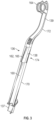
- FIG. 3 shows a representative whip member 136 in isolation for purposes of illustration.
- the whip member 136 can comprise a main body 138 having a first end portion 137 (also referred to as a proximal end or portion) and a second end portion 139 (also referred to as a distal end or portion). As shown in FIG.
- the first end portion 137 can be coupled to the housing 130 (e.g., attached inside the housing and extending through an opening in the top of the housing) such that the second end portion 139 is disposed above the housing 130, and with the main body 138 at an angle to the housing.
- the main body 138 can define a channel or recess 160 ( FIG. 3 ) extending axially along at least a portion of the main body's length or longitudinal axis, and comprises a flexible portion 162 located approximately in the middle of the main body 138.
- the channel 160 is defined in an exterior surface of the main body 138, although in other embodiments the channel 160 may extend at least partially within the main body.
- the second end portion 139 can comprise a pulley 164.
- a conduit 166 is shown extending from the housing 130, along the channel 160 of the whip member 136A, around the pulley 164, and back toward the housing.
- the conduit 166 can be configured to supply one or more utilities to an instrument or handpiece 168 coupled at the end of the conduit 166 and positioned in the holding area 132A.
- the position and/or angle of the whip members 136 can be adjustable by the user in the field.
- the whip members 136 can comprise adjustment or positioning assemblies configured to allow a user to selectively position at least the second end portion 139 of the whip members about one or more axes.
- FIG. 4 illustrates an exploded view of a representative embodiment of a whip member 136.
- the whip member 136 can comprise a first or lower member 170 (also referred to as a lower portion), a second or upper member 172 (also referred to as an upper portion), and a positioning assembly generally indicated at 174.
- the positioning assembly 174 can comprise a first hub, support, or attachment member 176, a second hub, support, or attachment member 178, and two biasing members configured as tension coil spring members 180 and 182.
- the spring members 180 and 182 can be spaced apart from each other across a width of the main body 138 on opposite sides of its longitudinal axis.
- the spring member 180 can comprise a first or lower mounting portion configured as a pin member 184, and a second or upper mounting portion configured as a pin member 186. Referring to FIG. 5 , the lower pin member 184 can be received in corresponding mounting portions 188 and 190 on the first attachment member 176. In certain embodiments, the pin member 184 can comprise a keyed shape configured to correspond to a slot in the attachment member 176. This can prevent the spring assembly from rotating relative to the attachment member 176, while allowing motion of the spring member 180 along the pin's axis. In certain embodiments, the connections between the spring member 180 and the pin members 184 and 186 can be rigid such that rotation of the pin members relative to the spring relative can be prevented.
- the mounting portions 188 and 190 can be spaced apart to accommodate a control member or adjustment member configured as a rotatable knob 163.
- a sleeve member 161 can be located above the mounting member 190.
- the second pin member 186 of the spring member 180 can be received in a corresponding mounting portion 192 of the second attachment member 178.
- the mounting portion 192 can be configured to prevent rotation of the pin member 186 and the spring member 180.
- the second spring member 182 can be configured similarly to the first spring member 180, with pin members 181 and 183.
- the pin member 181 can be received in mounting portions 185 and 187 of the first attachment member 176, and the pin member 183 can be received in a mounting portion 194 of the second attachment member 178.
- An adjustment member 173 can be disposed on the pin member 181 between the mounting portions 185 and 187, and a sleeve member 189 can be disposed above the mounting portion 187.
- the adjustment members 163 and 173 can comprise a gear spline finish or a knurl finish to improve frictional engagement between the members 163, 173 and an adjustment tool, and/or between the members and a user's fingers.
- the attachment member 176 when assembled, can be received at least partially within the lower member 170, and the attachment members 176 and 178 can be coupled together.
- the lower portion of the member 178 can be received in an opening defined in the top portion of the member 176.
- the second attachment member 178 can be configured to move, pivot, and/or rotate relative to the first attachment member 176, as described further below.
- the attachment member 176 can comprise a coupling member 191 configured to engage a corresponding lip or protrusion inside the lower member 170 to secure the positioning assembly 174 in place.
- the mounting portions 192 and 194 of the second attachment member 178 can be received in corresponding tubular portions 196 and 198 ( FIGS. 4 and 6 ) of the upper member 172.
- a cover member 165 ( FIG. 4 ) can at least partially enclose the positioning assembly 174.
- the cover member 165 is a flexible member, and forms a part of the flexible portion 162 located between the lower member 170 and the upper member 172. More particularly, the cover member 165 is configured to flex to allow the upper member 172 to move relative to the lower member 170.
- a guide or shaft 159 can extend between the lower member 170 and the upper member 172.
- the pulley 164 can comprise a hub 167, a rotating member 169, and a cover member 171 configured to be mounted at the distal end of the second member 172.
- the rotating member 169 can be snapped onto or attached to an axle and a cover that are part of a unitary construction including the second member 172.
- the spring member 180 can extend between the pin members 184 and 186.
- the pin member 184 can be configured such that rotation of the adjustment member 163 moves or translates the spring member 180 axially relative to the first attachment member 176, thereby lengthening or shortening the portion of the lower pin 184 that protrudes from the mounting portion 188.
- the pin member 184 can comprise threads engaged with corresponding threads on the inner diameter of the adjustment member 163 such that rotation of the adjustment member 163 causes corresponding longitudinal motion of the pin member 184 through the adjustment member, thereby translating the spring member 180 axially relative to the attachment member 176.
- rotation of the adjustment member 173 can move the spring member 182 in a similar fashion.
- first and second attachment members 176 and 178 may be movable relative to each other, for example axially, pivotably, and/or rotationally, as the spring members 180 and 182 are moved by the adjustment members 163 and 173.
- axially moving the spring member 180 and/or 182 can change the position or orientation of the whip member 136, the upper member 172, the second attachment member 178, and/or the flexible portion 162, relative to the base 130.
- the upper member 172 can be angled, tilted, or rotated about the y-axis (extending out of the plane of the page in FIG. 6 ), or relative to a plane including the y-axis, to the left in FIG. 6 .
- the attachment member 178 can pivot relative to the attachment member 176 under the influence of the spring 180.
- the upper member 172 can be angled or tilted to the right in FIG. 6 (e.g., by pivoting the attachment member 178 relative to the attachment member 176).
- the motion of the attachment member 178 relative to the attachment member 176 can allow the springs 180 and 182 to remain at a substantially constant length as they are axially moved relative to the first attachment member 176.
- the upper portion 172 can be angled, tilted, or rotated about the x-axis (extending out of the plane of the page in FIG. 7 ), or relative to a plane including the x-axis.
- the upper portion 172 can be bent forward (e.g., toward the user).
- the upper portion 172 can be straightened, or angled backward (e.g., away from the user).
- the spring members 180 and 182 can also be moved independently to straighten, or achieve a desired positioning, of one whip member 136 relative to another on the delivery unit 152.
- the range of motion can be ⁇ 0.1 inch.
- the whip members 136 can be configured to be moved or bent forward (e.g., toward the holding areas 132A and 132B) when an instrument coupled to the particular whip member is in use.
- such motion is effected by bending or flexing the flexible portion 162 such that the upper portion 172 moves or pivots (e.g., downwardly) relative to the lower portion 170.
- the positioning assembly 174 can be configured to allow the upper portion 172 to move laterally, or front to back, as described above.
- the whip members 136 can be configured such that at least the adjustment members 163 and 173 can be accessed by a user.
- the positioning assembly 174 can be at least partially removed from the lower portion 170 to access the adjustment members 163 and 173, as shown in FIG. 9 .
- the upper portion 172 and/or the flexible portion 162 can be axially movable relative to the lower portion 170 such that the adjustment members 163 and 173 can be accessed by moving or pulling the upper and lower portions apart.
- the coupling member 191 can be disengaged, and the upper portion 172 and/or the flexible portion 162 can be moved such that the positioning assembly 174 is removed from the lower portion 170 to access the adjustment members 163 and 173.
- the cover member 165 of the flexible portion 162 may move with the upper portion 172 away from the lower portion 170.
- the lower and upper portions 170, 172 can be moved, pushed, or slid back together to enclose the adjustment members within the main body of the whip member.
- the adjustment members can be accessible by removing a removable panel from the main body of the conduit guide.
- making at least the adjustment members 163 and 173 selectively accessible can allow a technician at the factory, and/or a user in the field, to adjust the position and/or angle of whip members relative to other whip members on the same delivery unit, and/or relative to the delivery unit housing, to maintain an aesthetic appearance of the system and facilitate use of instruments coupled to the system.
- This can also allow positional adjustment of the whip members to compensate for misalignments arising due to variability in size, tolerances, spring constants, etc., of the constituent components.
- adjustments can also be made quickly and easily in the field as needed to compensate for, for example, changes in temperature and/or material properties over time.
- the adjustment members can be stowed, allowing the whip members to maintain a sleek outward appearance.
- the disclosed embodiments can also improve the ability to clean and disinfect the external surfaces of the whip members, while protecting the internal components from damage or deterioration by cleaning and/or disinfecting agents
- the singular forms “a,” “an,” and “the” include the plural forms unless the context clearly dictates otherwise. Additionally, the term “includes” means “comprises.” Further, the terms “coupled” and “associated” generally mean electrically, electromagnetically, and/or physically ( e . g ., mechanically or chemically) coupled or linked and does not exclude the presence of intermediate elements between the coupled or associated items absent specific contrary language.
- values, procedures, or apparatus may be referred to as "lowest,” “best,” “minimum,” or the like. It will be appreciated that such descriptions are intended to indicate that a selection among many alternatives can be made, and such selections need not be better, smaller, or otherwise preferable to other selections.
Landscapes
- Health & Medical Sciences (AREA)
- Life Sciences & Earth Sciences (AREA)
- Animal Behavior & Ethology (AREA)
- General Health & Medical Sciences (AREA)
- Public Health (AREA)
- Veterinary Medicine (AREA)
- Engineering & Computer Science (AREA)
- Water Supply & Treatment (AREA)
- Oral & Maxillofacial Surgery (AREA)
- Dentistry (AREA)
- Epidemiology (AREA)
- Dental Tools And Instruments Or Auxiliary Dental Instruments (AREA)
Description
- The present disclosure pertains to assemblies for adjusting the angle of whip assemblies on delivery systems for dental operatories.
- Dental operatory setups typically include control heads or dental delivery units for supplying utilities such as compressed air, water, electrical power, etc., to dental instruments by way of conduits. Such delivery units typically include a housing to which a plurality of conduits may be coupled to interconnect various dental instruments with the delivery unit. Such delivery units may be in the "traditional" style, in which conduits extend from the delivery unit without a guide, or a "continental" style, in which conduit guides known as "whips" extend from the delivery unit, and may be configured to flex to aid in positioning the conduits when the instruments are removed from their holding areas for use in treating a patient. When the dental practitioner is finished using an instrument and places it back in its holding area, the corresponding whip returns to its original, generally unflexed position, keeping the associated conduit out of the way and in an orderly arrangement. Due to variability in the components used to manufacture the whips, it can be difficult to achieve and maintain uniformity in angle and positioning of multiple whips on continental style delivery units when the instruments connected to the conduits are not in use and are placed in their respective holding areas. Accordingly, there exists a need for improvements to delivery units for dental operatories.
-
US 9 121 542 B2 - Certain embodiments of the disclosure pertain to positioning assemblies for whip arms, whip members, or conduit guides for dental delivery units. The present invention is defined by the independent claims. Further aspects are defined in the dependent claims.
-
-
FIG. 1 is a perspective view of a dental chair assembly, according to one embodiment. -
FIG. 2 is a perspective view of a dental delivery unit including a plurality of whip members, according to one embodiment. -
FIG. 3 is a perspective view of a representative embodiment of a whip member. -
FIG. 4 is an exploded perspective view of a whip member including a positioning assembly, according to one embodiment. -
FIG. 5 is a front elevation view of the positioning assembly ofFIG. 4 . -
FIG. 6 is a front elevation view of a portion of a whip member including the positioning assembly ofFIG. 5 with the cover removed for purposes of illustration. -
FIG. 7 is a side elevation view of a portion of a whip member including the positioning assembly ofFIG. 5 . -
FIG. 8 is a perspective view of the dental delivery unit ofFIG. 2 with a whip member shown bent forward in a use position. -
FIG. 9 is a perspective view of a whip member with the upper portion and lower portion separated to access adjustment knobs of a positioning assembly, according to one embodiment. - The present disclosure concerns positioning assemblies for positioning conduit guides coupled to delivery units for use in dental operatories. Continental style delivery systems or delivery units typically include elongated conduit guides known as whips or whip members, which attach to the delivery unit housing and guide utility conduits extending from the housing. The positioning assemblies described herein can be integrated at least partially within the body of the guides, and can be selectively accessible to adjust the position of the conduit guides from side-to-side and/or forward and aft.
- For example, certain embodiments described herein can include first and second attachment members coupled to each other, and first and second spring members laterally spaced apart and extending between the first and second attachment members. The positioning assemblies may be integrated into the bodies of the conduit guides near a center of the overall length of the guides. By axially moving or translating one or both of the spring members, and thereby moving the second or upper attachment member, the angle or lie of at least the upper portions of the conduit guides can be adjusted along multiple axes. Axial movement of the spring members can be accomplished by rotating adjustment members coupled to each spring member. The conduit guides can be configured such that at least the adjustment members can be selectively accessed and covered or stowed. This can allow a technician at the factory, and/or a user in the field, to individually and repeatedly adjust the position of conduit guides relative to each other to facilitate the use of instruments coupled to the delivery system. The positioning assemblies can also be used to promote an aesthetically pleasing appearance of the system with multiple conduit guides arranged at the same angle, or substantially the same angle, relative to the delivery system housing, at least when the instruments connected to the conduits are not in use and are placed in their respective holding areas.
-
FIG. 1 is a perspective view of one example of a dental chair ortreatment assembly 100 having achair 112 and adental unit 120, which are described below in greater detail. Thechair 112 has abase 110, and aheight adjustment mechanism 114 coupled to thebase 110 and configured to change a height of thedental chair 112. InFIG. 1 , thechair 112 is shown in a fully reclined position with an upper end (head end) having ahead rest 113 at the right side of the figure, and an oppositelower end 115 at the left side of the figure. The angle of thechair 112 between thehead rest 113 and thelower end 115 is fully adjustable about a hinged joint between the upper and lower sections from the fully reclined position as shown through a range of positions up to and including a fully seated position. - As used herein, the
dental unit 120, sometimes referred to as the unit or the dental operative unit, refers to the device or devices that provide the necessary utilities and amenities to provide treatment to the patient (including but not limited to compressed air, water, suction, electricity, data, touch or other control for integrated devices, holders for instruments and other components, etc.). Thedental unit 120 can include one or more arms, such as thedental unit arm 140 in the illustrated implementation, to support a dental delivery unit 152 (also referred to as a delivery unit, a control head, or a delivery system) and/or other equipment. Thedelivery unit 152 is supported by thedental unit arm 140 to provide the instruments and components of thedental unit 120 at positions convenient for treatment and is movable, e.g., to provide space for ingress and egress from thechair 112. - In the illustrated configuration, the
dental unit arm 140 has a proximal end mounted to thechair 112 at a dentalunit arm mount 135, which in the illustrated implementation is positioned below the lower section of thechair 112, e.g., on a lower surface thereof. Thedental unit arm 140 is pivotably coupled to the dentalunit arm mount 135 by a dentalunit arm pivot 142. In the illustrated implementation, thedental unit arm 140 is configured to pivot in a substantially horizontal plane. Thedental unit arm 140 can further compriseportions joint 145. Although thedelivery unit 152 is shown coupled to thedental unit arm 140 in the illustrated configuration, in other embodiments thedelivery unit 152 can be a standalone unit that is not coupled to the chair assembly. - The
delivery unit 152 can provide connections for one or more of liquid (water), compressed air, suction, electrical power, data, etc., various instruments and devices that use these connections, storage for the instruments and devices, and/or a display, among other components. Thedelivery unit 152 can have ahandle 155 for a user to grasp with his or her hand to facilitate moving thedelivery unit 152, which is frequently repositioned when performing dental procedures. Thehandle 155 can include an actuator, which may be mechanical, electrical, active, passive or combinations thereof. In some implementations, thehandle 155 has a passive actuator to operate apositive positioning device 144a, apositive positioning device 144b and/or a brake (not shown). Further details regarding thearm 140, and control of its position using the controls of thedelivery unit 152, can be found inU.S. Publication No. 2020/0016774 . -
FIG. 2 illustrates thedelivery unit 152 in greater detail. In the illustrated configuration, thedelivery unit 152 is configured as a "continental" style delivery system including a base having a main housing orenclosure 130, twoinstrument holding areas screen 134, and a conduit management system comprising a plurality of conduit guides configured as whip members 136 (six in the illustrated configuration).FIG. 3 shows arepresentative whip member 136 in isolation for purposes of illustration. Thewhip member 136 can comprise amain body 138 having a first end portion 137 (also referred to as a proximal end or portion) and a second end portion 139 (also referred to as a distal end or portion). As shown inFIG. 2 , thefirst end portion 137 can be coupled to the housing 130 (e.g., attached inside the housing and extending through an opening in the top of the housing) such that thesecond end portion 139 is disposed above thehousing 130, and with themain body 138 at an angle to the housing. Themain body 138 can define a channel or recess 160 (FIG. 3 ) extending axially along at least a portion of the main body's length or longitudinal axis, and comprises a flexible portion 162 located approximately in the middle of themain body 138. In the illustrated configuration, thechannel 160 is defined in an exterior surface of themain body 138, although in other embodiments thechannel 160 may extend at least partially within the main body. Thesecond end portion 139 can comprise apulley 164. - Returning to
FIG. 2 , and referring to a representative whip member 136A, aconduit 166 is shown extending from thehousing 130, along thechannel 160 of the whip member 136A, around thepulley 164, and back toward the housing. Theconduit 166 can be configured to supply one or more utilities to an instrument orhandpiece 168 coupled at the end of theconduit 166 and positioned in theholding area 132A. - In certain embodiments, the position and/or angle of the
whip members 136 can be adjustable by the user in the field. To this end, thewhip members 136 can comprise adjustment or positioning assemblies configured to allow a user to selectively position at least thesecond end portion 139 of the whip members about one or more axes. For example,FIG. 4 illustrates an exploded view of a representative embodiment of awhip member 136. Thewhip member 136 can comprise a first or lower member 170 (also referred to as a lower portion), a second or upper member 172 (also referred to as an upper portion), and a positioning assembly generally indicated at 174. Thepositioning assembly 174 can comprise a first hub, support, orattachment member 176, a second hub, support, orattachment member 178, and two biasing members configured as tensioncoil spring members spring members main body 138 on opposite sides of its longitudinal axis. - The
spring member 180 can comprise a first or lower mounting portion configured as apin member 184, and a second or upper mounting portion configured as apin member 186. Referring toFIG. 5 , thelower pin member 184 can be received in corresponding mountingportions first attachment member 176. In certain embodiments, thepin member 184 can comprise a keyed shape configured to correspond to a slot in theattachment member 176. This can prevent the spring assembly from rotating relative to theattachment member 176, while allowing motion of thespring member 180 along the pin's axis. In certain embodiments, the connections between thespring member 180 and thepin members - The mounting
portions rotatable knob 163. Asleeve member 161 can be located above the mountingmember 190. Thesecond pin member 186 of thespring member 180 can be received in a corresponding mountingportion 192 of thesecond attachment member 178. In certain embodiments, the mountingportion 192 can be configured to prevent rotation of thepin member 186 and thespring member 180. - The
second spring member 182 can be configured similarly to thefirst spring member 180, withpin members pin member 181 can be received in mountingportions first attachment member 176, and thepin member 183 can be received in a mountingportion 194 of thesecond attachment member 178. Anadjustment member 173 can be disposed on thepin member 181 between the mountingportions sleeve member 189 can be disposed above the mountingportion 187. In some embodiments, theadjustment members members - Referring to
FIGS. 4-6 , when assembled, theattachment member 176 can be received at least partially within thelower member 170, and theattachment members member 178 can be received in an opening defined in the top portion of themember 176. In certain embodiments, thesecond attachment member 178 can be configured to move, pivot, and/or rotate relative to thefirst attachment member 176, as described further below. Referring toFIG. 5 , theattachment member 176 can comprise acoupling member 191 configured to engage a corresponding lip or protrusion inside thelower member 170 to secure thepositioning assembly 174 in place. The mountingportions second attachment member 178 can be received in correspondingtubular portions 196 and 198 (FIGS. 4 and6 ) of theupper member 172. A cover member 165 (FIG. 4 ) can at least partially enclose thepositioning assembly 174. Thecover member 165 is a flexible member, and forms a part of the flexible portion 162 located between thelower member 170 and theupper member 172. More particularly, thecover member 165 is configured to flex to allow theupper member 172 to move relative to thelower member 170. A guide orshaft 159 can extend between thelower member 170 and theupper member 172. - In the illustrated configuration, the
pulley 164 can comprise ahub 167, a rotatingmember 169, and acover member 171 configured to be mounted at the distal end of thesecond member 172. In other embodiments, the rotatingmember 169 can be snapped onto or attached to an axle and a cover that are part of a unitary construction including thesecond member 172. - Referring again to
FIG. 5 , thespring member 180 can extend between thepin members pin member 184 can be configured such that rotation of theadjustment member 163 moves or translates thespring member 180 axially relative to thefirst attachment member 176, thereby lengthening or shortening the portion of thelower pin 184 that protrudes from the mountingportion 188. For example, thepin member 184 can comprise threads engaged with corresponding threads on the inner diameter of theadjustment member 163 such that rotation of theadjustment member 163 causes corresponding longitudinal motion of thepin member 184 through the adjustment member, thereby translating thespring member 180 axially relative to theattachment member 176. Likewise, rotation of theadjustment member 173 can move thespring member 182 in a similar fashion. In certain embodiments, the first andsecond attachment members spring members adjustment members spring member 180 and/or 182 can change the position or orientation of thewhip member 136, theupper member 172, thesecond attachment member 178, and/or the flexible portion 162, relative to thebase 130. - Accordingly, referring to
FIG. 6 , by moving thespring member 180 axially toward the housing 130 (e.g., downwardly inFIG. 6 ) and holding the position of thespring member 182 constant (or moving thespring member 182 upwardly), theupper member 172 can be angled, tilted, or rotated about the y-axis (extending out of the plane of the page inFIG. 6 ), or relative to a plane including the y-axis, to the left inFIG. 6 . In certain embodiments, theattachment member 178 can pivot relative to theattachment member 176 under the influence of thespring 180. Likewise, by moving thespring member 182 downwardly and holding thespring member 180 at a constant position (and/or moving thespring member 180 upwardly), theupper member 172 can be angled or tilted to the right inFIG. 6 (e.g., by pivoting theattachment member 178 relative to the attachment member 176). In certain embodiments, the motion of theattachment member 178 relative to theattachment member 176 can allow thesprings first attachment member 176. - Referring to
FIG. 7 , by moving bothsprings members upper portion 172 can be angled, tilted, or rotated about the x-axis (extending out of the plane of the page inFIG. 7 ), or relative to a plane including the x-axis. For example, by moving bothsprings members upper portion 172 can be bent forward (e.g., toward the user). By moving bothspring members upper portion 172 can be straightened, or angled backward (e.g., away from the user). Thespring members whip member 136 relative to another on thedelivery unit 152. In particular embodiments, the range of motion can be ± 0.1 inch. - Referring to
FIG. 8 , in certain embodiments thewhip members 136 can be configured to be moved or bent forward (e.g., toward the holdingareas upper portion 172 moves or pivots (e.g., downwardly) relative to thelower portion 170. With theupper portion 172 pivoted toward thelower portion 170, thepositioning assembly 174 can be configured to allow theupper portion 172 to move laterally, or front to back, as described above. - The
whip members 136 can be configured such that at least theadjustment members positioning assembly 174 can be at least partially removed from thelower portion 170 to access theadjustment members FIG. 9 . In certain embodiments, theupper portion 172 and/or the flexible portion 162 can be axially movable relative to thelower portion 170 such that theadjustment members coupling member 191 can be disengaged, and theupper portion 172 and/or the flexible portion 162 can be moved such that thepositioning assembly 174 is removed from thelower portion 170 to access theadjustment members cover member 165 of the flexible portion 162 may move with theupper portion 172 away from thelower portion 170. When the adjustment is complete, the lower andupper portions - The configurations described herein can provide a number of advantages. For example, making at least the
adjustment members - In other embodiments, the positioning assembly can comprise a single spring member (e.g., for forward and aft movement or side-to-side movement), or more than two spring members. In yet other embodiments, one or both of the
spring members 180 and/or 182 can be configured as compression springs. In yet other embodiments, thepositioning assembly 174 can comprise other types of actuators, such as linear actuators including leadscrews or translation screws, stepper motors, etc., in place of, or in combination with, thespring members adjustment members upper portions - For purposes of this description, certain aspects, advantages, and novel features of the embodiments of this disclosure are described herein. The disclosed methods, apparatus, and systems should not be construed as being limiting in any way. Instead, the present disclosure is directed toward all novel and nonobvious features and aspects of the various disclosed embodiments, alone and in various combinations and sub-combinations with one another. The methods, apparatus, and systems are not limited to any specific aspect or feature or combination thereof, nor do the disclosed embodiments require that any one or more specific advantages be present or problems be solved.
- Although the operations of some of the disclosed embodiments are described in a particular, sequential order for convenient presentation, it should be understood that this manner of description encompasses rearrangement, unless a particular ordering is required by specific language set forth below. For example, operations described sequentially may in some cases be rearranged or performed concurrently. Moreover, for the sake of simplicity, the attached figures may not show the various ways in which the disclosed methods can be used in conjunction with other methods.
- As used in this disclosure and in the claims, the singular forms "a," "an," and "the" include the plural forms unless the context clearly dictates otherwise. Additionally, the term "includes" means "comprises." Further, the terms "coupled" and "associated" generally mean electrically, electromagnetically, and/or physically (e.g., mechanically or chemically) coupled or linked and does not exclude the presence of intermediate elements between the coupled or associated items absent specific contrary language.
- In some examples, values, procedures, or apparatus may be referred to as "lowest," "best," "minimum," or the like. It will be appreciated that such descriptions are intended to indicate that a selection among many alternatives can be made, and such selections need not be better, smaller, or otherwise preferable to other selections.
- In the description, certain terms may be used such as "up," "down," "upper," "lower," "horizontal," "vertical," "left," "right," and the like. These terms are used, where applicable, to provide some clarity of description when dealing with relative relationships. But, these terms are not intended to imply absolute relationships, positions, and/or orientations. For example, with respect to an object, an "upper" surface can become a "lower" surface simply by turning the object over. Nevertheless, it is still the same object.
- Unless otherwise indicated, all numbers expressing quantities of components, forces, moments, molecular weights, percentages, temperatures, times, and so forth, as used in the specification or claims are to be understood as being modified by the term "about." Accordingly, unless otherwise indicated, implicitly or explicitly, the numerical parameters set forth are approximations that can depend on the desired properties sought and/or limits of detection under test conditions/methods familiar to those of ordinary skill in the art. When directly and explicitly distinguishing embodiments from discussed prior art, the embodiment numbers are not approximates unless the word "about" is recited. Furthermore, not all alternatives recited herein are equivalents.
Claims (13)
- A conduit guide, comprising:a main body (138) including a first portion (137), an intermediate flexible portion (162) and a second portion (139) movable relative to the first portion via the flexible portion, the first portion being configured for attachment to a dental delivery unit (152) and to extend along an inclined longitudinal axis, the main body defining a channel (160) along at least a portion of a length of the main body that is configured to receive a utility conduit (166); anda positioning assembly (174) at least partially disposed within the flexible portion of the main body, the positioning assembly including a first attachment member (176), a second attachment member (178), a biasing member (180 or 182), and an adjustment member (163 or 173), the biasing member being coupled to the first attachment member and to the second attachment member, and extending between the first attachment member and the second attachment member, the adjustment member being coupled to the biasing member and configured to axially move the biasing member to adjust a position of the second portion relative to the first portion when the conduit guide is mounted to the dental delivery unit;wherein the conduit guide is configured such that at least the adjustment member of the positioning assembly can be selectively accessed and enclosed within the main body.
- The conduit guide of claim 1, wherein the second portion of the main body is axially movable relative to the first portion of the main body to access and enclose the adjustment member.
- The conduit guide of claim 1 or claim 2, wherein the positioning assembly is configured to adjust a position of the second portion of the main body by moving the second attachment member relative to the first attachment member.
- The conduit guide of claim 3, wherein:the biasing member is a first biasing member (180 or 182); andthe positioning assembly further comprises a second biasing member (180 or 182) spaced apart from the first biasing member across a width of the main body.
- The conduit guide of claim 4, wherein:the positioning assembly is configured such that axially moving the first biasing member relative to the second biasing member moves the second portion of the conduit guide about a first axis; andmoving the first biasing member and the second biasing member downwardly, or moving the first biasing member and the second biasing member upwardly, moves the second portion of the conduit guide about a second axis perpendicular to the first axis, and optionally, wherein the first biasing member and the second biasing member are configured as tension coil springs.
- The conduit guide of any of claims 1-5, wherein:the first attachment member comprises a first mounting portion (188 or 185) and a second mounting portion (190 or 187), the second mounting portion being axially spaced apart from the first mounting portion, the first and second mounting portions being configured to receive the biasing member; andthe adjustment member is disposed between the first and second mounting portions.
- The conduit guide of claim 6, wherein the second attachment member comprises a third mounting portion (192 or 194) configured to receive the biasing member such that the biasing member extends between the second mounting portion of the first attachment member to the third mounting portion of the second attachment member.
- The conduit guide of claim 7, wherein:the biasing member is configured as a tension coil spring;the tension coil spring comprises a first pin member (184 or 181) coupled at one end of the tension coil spring and a second pin member (186 or 183) coupled at the opposite end of the tension coil spring; andthe first pin member is received between the first mounting portion and the second mounting portion of the first attachment member.
- The conduit guide of claim 8, wherein the first pin member is configured to extend through the adjustment member and engage the adjustment member such that rotation of the adjustment member causes longitudinal motion of the first pin member relative to the first attachment member, thereby axially moving the tension coil spring.
- A dental delivery unit configured to provide one or more utilities for performing dental procedures on a patient, the dental delivery unit comprising the conduit guide of any of claims 1-9.
- A dental chair assembly, comprising:a chair (112); anda dental unit (120) coupled to the chair, the dental unit comprising the dental delivery unit of claim 10.
- A method of using the conduit guide of any of claims 1-9, comprising:accessing the positioning assembly within the main body of the conduit guide;with the adjustment member, moving the biasing member to adjust a position of the conduit guide; andcovering the positioning assembly.
- An assembly, comprising:a delivery unit configured to deliver utilities to dental instruments; anda conduit guide of any of claims 1 to 9 coupled to the delivery unit and extending outwardly therefrom.
Applications Claiming Priority (2)
| Application Number | Priority Date | Filing Date | Title |
|---|---|---|---|
| US16/387,278 US11484385B2 (en) | 2019-04-17 | 2019-04-17 | Positioning assembly for control whip of dental delivery unit |
| PCT/US2020/028537 WO2020214822A1 (en) | 2019-04-17 | 2020-04-16 | Positioning assembly for control whip of dental delivery unit |
Publications (4)
| Publication Number | Publication Date |
|---|---|
| EP3955875A1 EP3955875A1 (en) | 2022-02-23 |
| EP3955875A4 EP3955875A4 (en) | 2023-03-15 |
| EP3955875C0 EP3955875C0 (en) | 2025-02-19 |
| EP3955875B1 true EP3955875B1 (en) | 2025-02-19 |
Family
ID=72833398
Family Applications (1)
| Application Number | Title | Priority Date | Filing Date |
|---|---|---|---|
| EP20791439.1A Active EP3955875B1 (en) | 2019-04-17 | 2020-04-16 | Positioning assembly for control whip of dental delivery unit |
Country Status (7)
| Country | Link |
|---|---|
| US (1) | US11484385B2 (en) |
| EP (1) | EP3955875B1 (en) |
| CN (1) | CN114007568B (en) |
| AU (1) | AU2020257229B2 (en) |
| CA (1) | CA3135865C (en) |
| PL (1) | PL3955875T3 (en) |
| WO (1) | WO2020214822A1 (en) |
Families Citing this family (3)
| Publication number | Priority date | Publication date | Assignee | Title |
|---|---|---|---|---|
| EP3711737B1 (en) * | 2017-11-17 | 2023-06-07 | Takara Belmont Corporation | Instrument hose supporting device, and dental treatment apparatus having instrument hose supporting device |
| KR20250111534A (en) * | 2024-01-15 | 2025-07-22 | 주식회사 덴티움 | Handpiece assembly and dental unit chair having the same |
| EP4609824A1 (en) * | 2024-01-15 | 2025-09-03 | Dentium Co., Ltd. | Handpiece assembly and dental unit chair having same |
Family Cites Families (13)
| Publication number | Priority date | Publication date | Assignee | Title |
|---|---|---|---|---|
| DE2849035A1 (en) * | 1978-11-11 | 1980-05-22 | Ritter Ag | DENTAL TREATMENT DEVICE |
| US5334018A (en) * | 1992-12-08 | 1994-08-02 | Mdt Corporation | Dental control unit with removable cover |
| US5297961A (en) * | 1993-04-20 | 1994-03-29 | Mdt Corporation | Dental control unit with articulated whip arms |
| US5328209A (en) * | 1993-07-20 | 1994-07-12 | Cromwell Steve D | Vehicle exhaust stack joint yieldable in all directions |
| JP2884382B2 (en) * | 1993-08-13 | 1999-04-19 | ホーヤ株式会社 | Medical laser equipment |
| JP4241133B2 (en) * | 2003-03-27 | 2009-03-18 | 株式会社モリタ製作所 | Dental examination table |
| DE102006051497A1 (en) * | 2006-10-31 | 2008-05-08 | Kaltenbach & Voigt Gmbh | Device for holding at least one medical or dental medical instrument |
| DE102008023842A1 (en) | 2008-05-16 | 2009-11-19 | Kaltenbach & Voigt Gmbh | Medical or dental instrument holding device, has pivoted lever supported at pivoted lever support, such that lever is pivotable in pivoting joint between stand-by and operating positions, where joint is arranged in front area of support |
| US20100129769A1 (en) * | 2008-11-23 | 2010-05-27 | Nilton Albano Junge | Dental Delivery System |
| USD605772S1 (en) | 2009-01-16 | 2009-12-08 | Midmark Corporation | Dental instrument delivery unit |
| JP5714521B2 (en) * | 2012-02-23 | 2015-05-07 | 株式会社モリタ製作所 | Rotation support mechanism and laser device |
| ITUB20153862A1 (en) * | 2015-09-24 | 2017-03-24 | Cefla S C | MODULAR STRUCTURE FOR A DENTAL MEETING |
| CN107174466A (en) * | 2017-06-26 | 2017-09-19 | 苏州威新锋医疗科技有限公司 | A kind of dental therapeutic apparatus moving assembly |
-
2019
- 2019-04-17 US US16/387,278 patent/US11484385B2/en active Active
-
2020
- 2020-04-16 AU AU2020257229A patent/AU2020257229B2/en active Active
- 2020-04-16 PL PL20791439.1T patent/PL3955875T3/en unknown
- 2020-04-16 CA CA3135865A patent/CA3135865C/en active Active
- 2020-04-16 WO PCT/US2020/028537 patent/WO2020214822A1/en not_active Ceased
- 2020-04-16 EP EP20791439.1A patent/EP3955875B1/en active Active
- 2020-04-16 CN CN202080028459.6A patent/CN114007568B/en active Active
Also Published As
| Publication number | Publication date |
|---|---|
| EP3955875A4 (en) | 2023-03-15 |
| WO2020214822A1 (en) | 2020-10-22 |
| AU2020257229A1 (en) | 2021-10-28 |
| CN114007568A (en) | 2022-02-01 |
| EP3955875A1 (en) | 2022-02-23 |
| PL3955875T3 (en) | 2025-09-01 |
| CA3135865A1 (en) | 2020-10-22 |
| US20200330183A1 (en) | 2020-10-22 |
| CN114007568B (en) | 2024-11-08 |
| CA3135865C (en) | 2025-05-13 |
| AU2020257229B2 (en) | 2025-01-23 |
| EP3955875C0 (en) | 2025-02-19 |
| US11484385B2 (en) | 2022-11-01 |
Similar Documents
| Publication | Publication Date | Title |
|---|---|---|
| AU2020257229B2 (en) | Positioning assembly for control whip of dental delivery unit | |
| US12232911B2 (en) | Instrument holder | |
| US6899307B2 (en) | Carrier system for a medical apparatus | |
| EP1396235B1 (en) | Surgical console | |
| EP2429441B1 (en) | Remote centre of motion positioner | |
| EP3096671B1 (en) | Robotic actuator for transesophageal echocardiography probe | |
| US20150005784A2 (en) | Device for Supporting and Positioning of a Surgical Instrument and/or an Endoscope for Use in Minimal-Invasive Surgery and a Surgical Robotic System | |
| EP3934509B1 (en) | An endoscope | |
| US12042441B2 (en) | Integrated patient support and equipment for medical procedures | |
| CN119700311B (en) | For slender tools robot system for alignment | |
| EP2177195B1 (en) | Dental apparatus having an adjustable articulated arm | |
| JPH09149877A (en) | Endoscope holding device | |
| US20040094676A1 (en) | Surgical microscope apparatus | |
| JP2004290429A (en) | Dental table | |
| WO2025099633A1 (en) | Ergonomic adjustments for a physician console |
Legal Events
| Date | Code | Title | Description |
|---|---|---|---|
| STAA | Information on the status of an ep patent application or granted ep patent |
Free format text: STATUS: THE INTERNATIONAL PUBLICATION HAS BEEN MADE |
|
| PUAI | Public reference made under article 153(3) epc to a published international application that has entered the european phase |
Free format text: ORIGINAL CODE: 0009012 |
|
| STAA | Information on the status of an ep patent application or granted ep patent |
Free format text: STATUS: REQUEST FOR EXAMINATION WAS MADE |
|
| 17P | Request for examination filed |
Effective date: 20211021 |
|
| AK | Designated contracting states |
Kind code of ref document: A1 Designated state(s): AL AT BE BG CH CY CZ DE DK EE ES FI FR GB GR HR HU IE IS IT LI LT LU LV MC MK MT NL NO PL PT RO RS SE SI SK SM TR |
|
| DAV | Request for validation of the european patent (deleted) | ||
| DAX | Request for extension of the european patent (deleted) | ||
| RIC1 | Information provided on ipc code assigned before grant |
Ipc: A61C 19/00 20060101ALI20221102BHEP Ipc: A61G 15/16 20060101ALI20221102BHEP Ipc: A61G 15/18 20060101AFI20221102BHEP |
|
| A4 | Supplementary search report drawn up and despatched |
Effective date: 20230209 |
|
| RIC1 | Information provided on ipc code assigned before grant |
Ipc: A61C 19/00 20060101ALI20230203BHEP Ipc: A61G 15/16 20060101ALI20230203BHEP Ipc: A61G 15/18 20060101AFI20230203BHEP |
|
| GRAP | Despatch of communication of intention to grant a patent |
Free format text: ORIGINAL CODE: EPIDOSNIGR1 |
|
| STAA | Information on the status of an ep patent application or granted ep patent |
Free format text: STATUS: GRANT OF PATENT IS INTENDED |
|
| INTG | Intention to grant announced |
Effective date: 20240909 |
|
| GRAS | Grant fee paid |
Free format text: ORIGINAL CODE: EPIDOSNIGR3 |
|
| GRAA | (expected) grant |
Free format text: ORIGINAL CODE: 0009210 |
|
| STAA | Information on the status of an ep patent application or granted ep patent |
Free format text: STATUS: THE PATENT HAS BEEN GRANTED |
|
| AK | Designated contracting states |
Kind code of ref document: B1 Designated state(s): AL AT BE BG CH CY CZ DE DK EE ES FI FR GB GR HR HU IE IS IT LI LT LU LV MC MK MT NL NO PL PT RO RS SE SI SK SM TR |
|
| REG | Reference to a national code |
Ref country code: GB Ref legal event code: FG4D |
|
| REG | Reference to a national code |
Ref country code: CH Ref legal event code: EP |
|
| REG | Reference to a national code |
Ref country code: IE Ref legal event code: FG4D |
|
| REG | Reference to a national code |
Ref country code: DE Ref legal event code: R096 Ref document number: 602020046388 Country of ref document: DE |
|
| U01 | Request for unitary effect filed |
Effective date: 20250226 |
|
| U07 | Unitary effect registered |
Designated state(s): AT BE BG DE DK EE FI FR IT LT LU LV MT NL PT RO SE SI Effective date: 20250307 |
|
| U20 | Renewal fee for the european patent with unitary effect paid |
Year of fee payment: 6 Effective date: 20250425 |
|
| PG25 | Lapsed in a contracting state [announced via postgrant information from national office to epo] |
Ref country code: RS Free format text: LAPSE BECAUSE OF FAILURE TO SUBMIT A TRANSLATION OF THE DESCRIPTION OR TO PAY THE FEE WITHIN THE PRESCRIBED TIME-LIMIT Effective date: 20250519 |
|
| PG25 | Lapsed in a contracting state [announced via postgrant information from national office to epo] |
Ref country code: ES Free format text: LAPSE BECAUSE OF FAILURE TO SUBMIT A TRANSLATION OF THE DESCRIPTION OR TO PAY THE FEE WITHIN THE PRESCRIBED TIME-LIMIT Effective date: 20250219 |
|
| PGFP | Annual fee paid to national office [announced via postgrant information from national office to epo] |
Ref country code: GB Payment date: 20250423 Year of fee payment: 6 |
|
| PG25 | Lapsed in a contracting state [announced via postgrant information from national office to epo] |
Ref country code: NO Free format text: LAPSE BECAUSE OF FAILURE TO SUBMIT A TRANSLATION OF THE DESCRIPTION OR TO PAY THE FEE WITHIN THE PRESCRIBED TIME-LIMIT Effective date: 20250519 Ref country code: IS Free format text: LAPSE BECAUSE OF FAILURE TO SUBMIT A TRANSLATION OF THE DESCRIPTION OR TO PAY THE FEE WITHIN THE PRESCRIBED TIME-LIMIT Effective date: 20250619 |
|
| PG25 | Lapsed in a contracting state [announced via postgrant information from national office to epo] |
Ref country code: HR Free format text: LAPSE BECAUSE OF FAILURE TO SUBMIT A TRANSLATION OF THE DESCRIPTION OR TO PAY THE FEE WITHIN THE PRESCRIBED TIME-LIMIT Effective date: 20250219 |
|
| PG25 | Lapsed in a contracting state [announced via postgrant information from national office to epo] |
Ref country code: GR Free format text: LAPSE BECAUSE OF FAILURE TO SUBMIT A TRANSLATION OF THE DESCRIPTION OR TO PAY THE FEE WITHIN THE PRESCRIBED TIME-LIMIT Effective date: 20250520 |
|
| PG25 | Lapsed in a contracting state [announced via postgrant information from national office to epo] |
Ref country code: SM Free format text: LAPSE BECAUSE OF FAILURE TO SUBMIT A TRANSLATION OF THE DESCRIPTION OR TO PAY THE FEE WITHIN THE PRESCRIBED TIME-LIMIT Effective date: 20250219 |
|
| PGFP | Annual fee paid to national office [announced via postgrant information from national office to epo] |
Ref country code: PL Payment date: 20250411 Year of fee payment: 6 |
|
| PG25 | Lapsed in a contracting state [announced via postgrant information from national office to epo] |
Ref country code: CZ Free format text: LAPSE BECAUSE OF FAILURE TO SUBMIT A TRANSLATION OF THE DESCRIPTION OR TO PAY THE FEE WITHIN THE PRESCRIBED TIME-LIMIT Effective date: 20250219 |
|
| PG25 | Lapsed in a contracting state [announced via postgrant information from national office to epo] |
Ref country code: SK Free format text: LAPSE BECAUSE OF FAILURE TO SUBMIT A TRANSLATION OF THE DESCRIPTION OR TO PAY THE FEE WITHIN THE PRESCRIBED TIME-LIMIT Effective date: 20250219 |
|
| REG | Reference to a national code |
Ref country code: CH Ref legal event code: H13 Free format text: ST27 STATUS EVENT CODE: U-0-0-H10-H13 (AS PROVIDED BY THE NATIONAL OFFICE) Effective date: 20251125 |
|
| PG25 | Lapsed in a contracting state [announced via postgrant information from national office to epo] |
Ref country code: MC Free format text: LAPSE BECAUSE OF FAILURE TO SUBMIT A TRANSLATION OF THE DESCRIPTION OR TO PAY THE FEE WITHIN THE PRESCRIBED TIME-LIMIT Effective date: 20250219 |
|
| PLBE | No opposition filed within time limit |
Free format text: ORIGINAL CODE: 0009261 |
|
| STAA | Information on the status of an ep patent application or granted ep patent |
Free format text: STATUS: NO OPPOSITION FILED WITHIN TIME LIMIT |
|
| PG25 | Lapsed in a contracting state [announced via postgrant information from national office to epo] |
Ref country code: CH Free format text: LAPSE BECAUSE OF NON-PAYMENT OF DUE FEES Effective date: 20250430 |
|
| 26N | No opposition filed |
Effective date: 20251120 |
|
| PG25 | Lapsed in a contracting state [announced via postgrant information from national office to epo] |
Ref country code: IE Free format text: LAPSE BECAUSE OF NON-PAYMENT OF DUE FEES Effective date: 20250416 |