EP3955838B1 - Spinal implant system - Google Patents
Spinal implant system Download PDFInfo
- Publication number
- EP3955838B1 EP3955838B1 EP19925196.8A EP19925196A EP3955838B1 EP 3955838 B1 EP3955838 B1 EP 3955838B1 EP 19925196 A EP19925196 A EP 19925196A EP 3955838 B1 EP3955838 B1 EP 3955838B1
- Authority
- EP
- European Patent Office
- Prior art keywords
- tabs
- cap
- implant support
- extender
- surgical
- Prior art date
- Legal status (The legal status is an assumption and is not a legal conclusion. Google has not performed a legal analysis and makes no representation as to the accuracy of the status listed.)
- Active
Links
Images




Classifications
-
- A—HUMAN NECESSITIES
- A61—MEDICAL OR VETERINARY SCIENCE; HYGIENE
- A61B—DIAGNOSIS; SURGERY; IDENTIFICATION
- A61B17/00—Surgical instruments, devices or methods
- A61B17/56—Surgical instruments or methods for treatment of bones or joints; Devices specially adapted therefor
- A61B17/58—Surgical instruments or methods for treatment of bones or joints; Devices specially adapted therefor for osteosynthesis, e.g. bone plates, screws or setting implements
- A61B17/68—Internal fixation devices, including fasteners and spinal fixators, even if a part thereof projects from the skin
- A61B17/70—Spinal positioners or stabilisers, e.g. stabilisers comprising fluid filler in an implant
- A61B17/7074—Tools specially adapted for spinal fixation operations other than for bone removal or filler handling
- A61B17/7083—Tools for guidance or insertion of tethers, rod-to-anchor connectors, rod-to-rod connectors, or longitudinal elements
- A61B17/7085—Tools for guidance or insertion of tethers, rod-to-anchor connectors, rod-to-rod connectors, or longitudinal elements for insertion of a longitudinal element down one or more hollow screw or hook extensions, i.e. at least a part of the element within an extension has a component of movement parallel to the extension's axis
-
- A—HUMAN NECESSITIES
- A61—MEDICAL OR VETERINARY SCIENCE; HYGIENE
- A61F—FILTERS IMPLANTABLE INTO BLOOD VESSELS; PROSTHESES; DEVICES PROVIDING PATENCY TO, OR PREVENTING COLLAPSING OF, TUBULAR STRUCTURES OF THE BODY, e.g. STENTS; ORTHOPAEDIC, NURSING OR CONTRACEPTIVE DEVICES; FOMENTATION; TREATMENT OR PROTECTION OF EYES OR EARS; BANDAGES, DRESSINGS OR ABSORBENT PADS; FIRST-AID KITS
- A61F2/00—Filters implantable into blood vessels; Prostheses, i.e. artificial substitutes or replacements for parts of the body; Appliances for connecting them with the body; Devices providing patency to, or preventing collapsing of, tubular structures of the body, e.g. stents
- A61F2/02—Prostheses implantable into the body
- A61F2/30—Joints
- A61F2/46—Special tools for implanting artificial joints
- A61F2/4603—Special tools for implanting artificial joints for insertion or extraction of endoprosthetic joints or of accessories thereof
- A61F2/4611—Special tools for implanting artificial joints for insertion or extraction of endoprosthetic joints or of accessories thereof of spinal prostheses
-
- A—HUMAN NECESSITIES
- A61—MEDICAL OR VETERINARY SCIENCE; HYGIENE
- A61F—FILTERS IMPLANTABLE INTO BLOOD VESSELS; PROSTHESES; DEVICES PROVIDING PATENCY TO, OR PREVENTING COLLAPSING OF, TUBULAR STRUCTURES OF THE BODY, e.g. STENTS; ORTHOPAEDIC, NURSING OR CONTRACEPTIVE DEVICES; FOMENTATION; TREATMENT OR PROTECTION OF EYES OR EARS; BANDAGES, DRESSINGS OR ABSORBENT PADS; FIRST-AID KITS
- A61F2/00—Filters implantable into blood vessels; Prostheses, i.e. artificial substitutes or replacements for parts of the body; Appliances for connecting them with the body; Devices providing patency to, or preventing collapsing of, tubular structures of the body, e.g. stents
- A61F2/02—Prostheses implantable into the body
- A61F2/30—Joints
- A61F2/44—Joints for the spine, e.g. vertebrae, spinal discs
- A61F2/442—Intervertebral or spinal discs, e.g. resilient
-
- A—HUMAN NECESSITIES
- A61—MEDICAL OR VETERINARY SCIENCE; HYGIENE
- A61B—DIAGNOSIS; SURGERY; IDENTIFICATION
- A61B17/00—Surgical instruments, devices or methods
- A61B17/56—Surgical instruments or methods for treatment of bones or joints; Devices specially adapted therefor
- A61B17/58—Surgical instruments or methods for treatment of bones or joints; Devices specially adapted therefor for osteosynthesis, e.g. bone plates, screws or setting implements
- A61B17/68—Internal fixation devices, including fasteners and spinal fixators, even if a part thereof projects from the skin
- A61B17/70—Spinal positioners or stabilisers, e.g. stabilisers comprising fluid filler in an implant
- A61B17/7001—Screws or hooks combined with longitudinal elements which do not contact vertebrae
- A61B17/7032—Screws or hooks with U-shaped head or back through which longitudinal rods pass
-
- A—HUMAN NECESSITIES
- A61—MEDICAL OR VETERINARY SCIENCE; HYGIENE
- A61B—DIAGNOSIS; SURGERY; IDENTIFICATION
- A61B17/00—Surgical instruments, devices or methods
- A61B17/56—Surgical instruments or methods for treatment of bones or joints; Devices specially adapted therefor
- A61B17/58—Surgical instruments or methods for treatment of bones or joints; Devices specially adapted therefor for osteosynthesis, e.g. bone plates, screws or setting implements
- A61B17/68—Internal fixation devices, including fasteners and spinal fixators, even if a part thereof projects from the skin
- A61B17/70—Spinal positioners or stabilisers, e.g. stabilisers comprising fluid filler in an implant
- A61B17/7074—Tools specially adapted for spinal fixation operations other than for bone removal or filler handling
- A61B17/7076—Tools specially adapted for spinal fixation operations other than for bone removal or filler handling for driving, positioning or assembling spinal clamps or bone anchors specially adapted for spinal fixation
-
- A—HUMAN NECESSITIES
- A61—MEDICAL OR VETERINARY SCIENCE; HYGIENE
- A61B—DIAGNOSIS; SURGERY; IDENTIFICATION
- A61B90/00—Instruments, implements or accessories specially adapted for surgery or diagnosis and not covered by any of the groups A61B1/00 - A61B50/00, e.g. for luxation treatment or for protecting wound edges
- A61B90/03—Automatic limiting or abutting means, e.g. for safety
- A61B2090/037—Automatic limiting or abutting means, e.g. for safety with a frangible part, e.g. by reduced diameter
-
- A—HUMAN NECESSITIES
- A61—MEDICAL OR VETERINARY SCIENCE; HYGIENE
- A61B—DIAGNOSIS; SURGERY; IDENTIFICATION
- A61B90/00—Instruments, implements or accessories specially adapted for surgery or diagnosis and not covered by any of the groups A61B1/00 - A61B50/00, e.g. for luxation treatment or for protecting wound edges
- A61B90/08—Accessories or related features not otherwise provided for
- A61B2090/0807—Indication means
- A61B2090/0811—Indication means for the position of a particular part of an instrument with respect to the rest of the instrument, e.g. position of the anvil of a stapling instrument
-
- A—HUMAN NECESSITIES
- A61—MEDICAL OR VETERINARY SCIENCE; HYGIENE
- A61F—FILTERS IMPLANTABLE INTO BLOOD VESSELS; PROSTHESES; DEVICES PROVIDING PATENCY TO, OR PREVENTING COLLAPSING OF, TUBULAR STRUCTURES OF THE BODY, e.g. STENTS; ORTHOPAEDIC, NURSING OR CONTRACEPTIVE DEVICES; FOMENTATION; TREATMENT OR PROTECTION OF EYES OR EARS; BANDAGES, DRESSINGS OR ABSORBENT PADS; FIRST-AID KITS
- A61F2/00—Filters implantable into blood vessels; Prostheses, i.e. artificial substitutes or replacements for parts of the body; Appliances for connecting them with the body; Devices providing patency to, or preventing collapsing of, tubular structures of the body, e.g. stents
- A61F2/02—Prostheses implantable into the body
- A61F2/30—Joints
- A61F2/30721—Accessories
- A61F2/30744—End caps, e.g. for closing an endoprosthetic cavity
-
- A—HUMAN NECESSITIES
- A61—MEDICAL OR VETERINARY SCIENCE; HYGIENE
- A61F—FILTERS IMPLANTABLE INTO BLOOD VESSELS; PROSTHESES; DEVICES PROVIDING PATENCY TO, OR PREVENTING COLLAPSING OF, TUBULAR STRUCTURES OF THE BODY, e.g. STENTS; ORTHOPAEDIC, NURSING OR CONTRACEPTIVE DEVICES; FOMENTATION; TREATMENT OR PROTECTION OF EYES OR EARS; BANDAGES, DRESSINGS OR ABSORBENT PADS; FIRST-AID KITS
- A61F2/00—Filters implantable into blood vessels; Prostheses, i.e. artificial substitutes or replacements for parts of the body; Appliances for connecting them with the body; Devices providing patency to, or preventing collapsing of, tubular structures of the body, e.g. stents
- A61F2/02—Prostheses implantable into the body
- A61F2/30—Joints
- A61F2/44—Joints for the spine, e.g. vertebrae, spinal discs
- A61F2/4455—Joints for the spine, e.g. vertebrae, spinal discs for the fusion of spinal bodies, e.g. intervertebral fusion of adjacent spinal bodies, e.g. fusion cages
-
- A—HUMAN NECESSITIES
- A61—MEDICAL OR VETERINARY SCIENCE; HYGIENE
- A61F—FILTERS IMPLANTABLE INTO BLOOD VESSELS; PROSTHESES; DEVICES PROVIDING PATENCY TO, OR PREVENTING COLLAPSING OF, TUBULAR STRUCTURES OF THE BODY, e.g. STENTS; ORTHOPAEDIC, NURSING OR CONTRACEPTIVE DEVICES; FOMENTATION; TREATMENT OR PROTECTION OF EYES OR EARS; BANDAGES, DRESSINGS OR ABSORBENT PADS; FIRST-AID KITS
- A61F2220/00—Fixations or connections for prostheses classified in groups A61F2/00 - A61F2/26 or A61F2/82 or A61F9/00 or A61F11/00 or subgroups thereof
- A61F2220/0025—Connections or couplings between prosthetic parts, e.g. between modular parts; Connecting elements
Definitions
- the present disclosure generally relates to medical devices for the treatment of musculoskeletal disorders, and more particularly to a spinal implant system and an implant support cap.
- Spinal pathologies and disorders such as kyphosis, scoliosis and other curvature abnormalities, degenerative disc disease, disc herniation, osteoporosis, spondylolisthesis, stenosis, tumor and fracture may result from factors including trauma, disease and degenerative conditions caused by injury and aging.
- Spinal disorders typically result in symptoms including deformity, pain, nerve damage, and partial or complete loss of mobility.
- the exemplary embodiments of the surgical system disclosed are discussed in terms of medical devices for the treatment of musculoskeletal disorders and more particularly, in terms of a spinal implant system. Associated methods are also described herein to aid understanding of the invention, but these do not form part of the claimed invention. Furthermore, illustrative methods of use and treatments are discussed to further the understanding of the inventive implant support cap and the inventive spinal implant system.
- the systems of the present disclosure comprise medical devices including surgical instruments and implants that can be employed with a surgical treatment, as described herein, for example, with a cervical, thoracic, lumbar and/or sacral region of a spine.
- the surgical system of the present disclosure may also be alternatively employed with procedures for treating the lumbar, cervical, thoracic, sacral and pelvic regions of a spinal column.
- the surgical system of the present disclosure may also be used on animals, bone models and other non-living substrates, such as, for example, in training, testing and demonstration.
- treating or treatment includes preventing or prevention of disease or undesirable condition (e.g., preventing the disease from occurring in a patient, who may be predisposed to the disease but has not yet been diagnosed as having it).
- treating or treatment does not require complete alleviation of signs or symptoms, does not require a cure, and specifically includes procedures that have only a marginal effect on the patient.
- Treatment can include inhibiting the disease, e.g., arresting its development, or relieving the disease, e.g., causing regression of the disease.
- treatment can include reducing acute or chronic inflammation; alleviating pain and mitigating and inducing re-growth of new ligament, bone and other tissues; as an adjunct in surgery; and/or any repair procedure.
- tissue includes soft tissue, ligaments, tendons, cartilage and/or bone unless specifically referred to otherwise.
- FIGS. 1-6 there are illustrated components of a surgical system, such as, for example, a spinal implant system 10. An embodiment of system 10 is shown in FIGs. 4-6 .
- FIGS. 1-3 show a few components of the system.
- Various components of spinal implant system 10 may have material composites, including the above materials, to achieve various desired characteristics such as strength, rigidity, elasticity, compliance, biomechanical performance, durability and radiolucency for imaging preference.
- the components of spinal implant system 10, individually or collectively, may also be fabricated from a heterogeneous material such as a combination of two or more of the above-described materials.
- the components of spinal implant system 10 may be monolithically formed, integrally connected or include fastening elements and/or instruments, as described herein.
- Spinal implant system 10 is employed, for example, with a fully open surgical procedure, a minimally invasive procedure including percutaneous techniques, and mini-open surgical techniques to deliver and introduce instrumentation and/or a spinal implant, such as, for example, a bone fastener, at a surgical site of a patient, which includes, for example, a spine.
- the spinal implant can include one or more components of one or more spinal constructs, such as, for example, interbody devices, interbody cages, bone fasteners, spinal rods, tethers, connectors, plates and/or bone graft, and can be employed with various surgical procedures including surgical treatment of a cervical, thoracic, lumbar and/or sacral region of a spine.
- Cap 12 extends between an end 14 and an end 16 defining an axis X1.
- Cap 12 includes a wall 24.
- Wall 24 includes portions 24a, 24b, 24c and 24d.
- Wall 24 includes an inner surface 26 extending along portions 24a, 24b, 24c and 24d.
- Surface 26 defines a cavity 28 configured for disposal of extender tabs 152, 152a.
- Cavity 28 includes a substantially rectangular configuration. In some embodiments, cavity 28 has various configurations including, for example, round, oval, polygonal, irregular, consistent, variable, uniform and non-uniform.
- Portion 24a includes a surface 41 connectable with a portion of extender tabs 152, 152a, such as, for example, a spring tip 178 or a spring tip 176, as described herein.
- Surface 41 defines at least one groove, such as, for example, a pocket 42, as shown in FIG. 1 .
- Portion 24a includes a pair of pockets 42. Pockets 42 are configured for a mating engagement with spring tips 178, as described herein.
- Surface 41 is configured as a lock 44 to resist and/or prevent disengagement of spring tips 178 from pocket 42, as described herein.
- Portion 24c includes a surface 50, similar to surface 41, connectable with a portion of extender tabs 152, 152a, such as, for example, spring tip 178 or spring tip 176, as described herein.
- Surface 50 defines at least one groove, such as, for example, a pocket 52, as shown in FIG. 2 .
- Portion 24c includes a pair of pockets 52, as shown in FIG. 2 .
- Pockets 52 are configured for a mating engagement with spring tips 176, as described herein.
- Pockets 52 are disposed in alignment with pockets 42, as shown in FIG. 1 , to facilitate engagement of spring tips 176.
- Surface 50 is configured as a lock 54 to resist and/or prevent disengagement of spring tips 176 from pocket 52, as described herein.
- Pockets 42, 52 are configured for engagement with spring tips 176, 178, as shown in FIG. 6 . Disposal of spring tips 176, 178 with pockets 42, 52 is configured to resist and/or prevent extender tabs 152, 152a from disengaging from cap 12. In some embodiments, pockets 42, 52 are disposed parallel to axis X1. In some embodiments, pockets 42, 52 are disposed at alternate orientations relative to axis a, such as, for example, at transverse, perpendicular and/or other angular orientations such as acute or obtuse, and/or may be offset or staggered. In some embodiments, locks 44, 54 are configured to provide audible and/or tactile indicia, such as, for example, an audible click indicating engagement of spring tips 176, 178 with cap 12.
- Wall 24 includes longitudinal rails 60a, 60b, 60c and 60d extending along axis X1.
- Rail 60a includes surface 64.
- Rail 60b includes a surface 66.
- Surfaces 64, 66 define a passageway, such as, for example, an axial slot 68.
- Slot 68 extends along axis X1.
- Slot 68 is configured to facilitate engagement of extender tab 152 with cap 12, as described herein.
- all or only a portion of surfaces 64, 66 may have alternate configurations, such as, for example, irregular, uniform, non-uniform, offset, staggered, tapered, arcuate or undulating. Surfaces 64, 66 direct and/or guide insertion of extender tab 152 into cavity 28.
- Rail 60c includes surface 70.
- Rail 60d includes a surface 72.
- Surfaces 70, 72 define a passageway, such as, for example, an axial slot 74. Slot 74 extends along axis X1. Slot 74 is configured to facilitate engagement of extender tab 152a with cap 12, as described herein.
- all or only a portion of surfaces 70, 72 may have alternate configurations, such as, for example, irregular, uniform, non-uniform, offset, staggered, tapered, arcuate or undulating. Surfaces 70, 72 direct and/or guide insertion of extender tab 152a into cavity 28.
- Extender tabs 152, 152a are configured to slide and/or translate along slots 68, 74 to position extender tabs 152, 152a within cavity 28 and into locking engagement with cap 12, as described herein. Slots 68, 74 are configured to splay extender tabs 152, 152a to facilitate engagement of spring tips 176, 178 with pockets 42, 52.
- Guide 40 is configured to guide and/or direct extender tabs 152, 152a into cavity 28.
- Guide 40 includes a distal surface 80 of wall 24 and an extension 82 extending from portion 24c, as shown in FIG. 2 .
- Surface 80 includes an opening 84 disposed in communication with slot 68.
- Surface 80 includes an opening 86 disposed in communication with slot 74.
- Surface 80 is configured to guide and/or direct extender tabs 152, 152a into slots 68, 74.
- Extension 82 includes a slot 92 and a slot 94.
- Slot 90 is disposed coaxially with slot 68, as shown in FIG. 1 .
- Slot 92 is disposed coaxially with slot 74.
- Extender tabs 152, 152a are guided, directed and/or aligned via slidable translation along slots 90, 92 into slots 68, 74. This configuration facilitates alignment of extender tabs 152, 152a for assembly with cap 12.
- Bone fastener assembly 150 includes a bone fastener 100.
- Bone fastener 100 includes a receiver 102.
- Receiver 102 is connected to extender tabs 152, 152a that extend along axis X1.
- Receiver 102 includes a pair of spaced apart arms 104, 106 that define an implant cavity configured for disposal of a component of a spinal construct, such as, for example, a spinal rod (not shown).
- Receiver 102 includes a socket configured for engagement with a surgical instrument.
- Receiver 102 includes an inner surface having a thread form located adjacent arm 104 and a thread form located adjacent arm 106. The thread forms of arms 104, 106 are configured for engagement with a coupling member.
- Bone fastener 100 includes a threaded shaft 116. Shaft 116 is configured to penetrate tissue, such as, for example, bone.
- Arm 104 includes a break away tab 120 that is frangibly connected to arm 104 such that manipulation of tab 120 relative to arm 104 can fracture and separate tab 120 from arm 104 at a predetermined force and/or torque limit, as described herein.
- Arm 106 includes a break away tab 130 that is frangibly connected to arm 106 such that manipulation of tab 130 relative to arm 106 can fracture and separate tab 130 from arm 106 at a predetermined force and/or torque limit, as described herein.
- force and/or torque is applied to tabs 120, 130 and resistance increases, for example, the predetermined torque and force limit is approached.
- tabs 120, 130 can fracture and separate at a predetermined force or torque limit, which may be in a range of approximately 2 Newton meters (N-m) to approximately 8 N-m.
- a predetermined force or torque limit which may be in a range of approximately 2 Newton meters (N-m) to approximately 8 N-m.
- tabs 120, 130 and arms 104, 106 may have the same or alternate cross section configurations, may be fabricated from a homogenous material or heterogeneously fabricated from different materials, and/or alternately formed of a material having a greater degree, characteristic or attribute of plastic deformability, frangible property and/or break away quality to facilitate fracture and separation of tabs 120, 130.
- spinal implant system 10 In assembly, operation and use, spinal implant system 10, similar to the systems described herein, is employed with a surgical procedure, such as, for example, a treatment of an applicable condition or injury of an affected section of a spinal column and adjacent areas within a body. In such treatments, one or all of the components of spinal implant system 10 can be delivered or utilized as a pre-assembled device or can be assembled in situ. Spinal implant system 10 may be completely or partially revised, removed or replaced.
- a medical practitioner obtains access to a surgical site in any appropriate manner, such as through incision and retraction of tissues.
- the inventive spinal implant system 10 can be used in any existing surgical method or technique including open surgery, mini-open surgery, minimally invasive surgery and percutaneous surgical implantation, whereby the vertebrae is accessed through a mini-incision, or sleeve that provides a protected passageway to the area. Once access to the surgical site is obtained, the particular surgical procedure can be performed for treating the spine disorder.
- a cutting instrument (not shown) creates a surgical pathway for implantation of components of spinal implant system 10.
- a preparation instrument (not shown) can be employed to prepare tissue surfaces of the vertebrae as well as for aspiration and irrigation of a surgical region.
- Pilot holes are made in selected levels of vertebrae for receiving shafts 116 of bone fastener assemblies 150.
- a surgical instrument such as, for example, a driver is connected to bone fastener 100 and bone fasteners 100 are engaged with vertebrae.
- Extender tabs 152, 152a are connected to bone fasteners 100, as described herein.
- Extender tabs 152, 152a are positioned adjacent cap 12, as shown in FIG. 4 . Extender tabs 152, 152a are aligned with guide 40 such that ramp 81 directs extender tabs 152, 152a into slots 92, 94 of extension 82. Extender tabs 152, 152a slide and/or translate along slots 92, 94. Slots 92, 94 direct and/or align extender tabs 152, 152a through openings 84, 86 into slots 68, 74.
- Extender tabs 152, 152a can be positioned with slots 92, 94 of extension 82 such that extender tabs 152, 152a slide and/or translate along slots 92, 94. Slots 92, 94 direct and/or align extender tabs 152, 152a through openings 84, 86 for disposal into slots 68, 74. Ramp 81 facilitates directing and/or aligning extender tabs 152, 152a into slots 92, 94 of extension 82.
- Spring tips 176, 178 are configured to engage surfaces 44, 54 and audible and/or tactile indicia, such as, for example, a click indicates engagement of spring tips 176, 178 with cap 12.
- Projection 34 resists and/or prevents disengagement of cap 12 from cavity 28 during insertion of extender tabs 152, 152a.
- a surgical procedure using an inventive spinal implant system can include delivering a spinal rod along the surgical pathway for connection with one or more bone fasteners 100.
- a reduction instrument (not shown) engages the spinal rod for reduction with receivers 102 and fixed thereto.
- a tab breaker is engaged with extender tabs 152, 152a and is manipulated to apply a force to extender tabs 152, 152a and/or tabs 120, 130. As the force applied reaches a selected torque limit, the tab breaker breaks off extender tabs 152, 152a and/or tabs 120, 130 from bone fasteners 100.
- spinal implant system 10 Upon completion of a procedure the surgical instruments, assemblies and non-implanted components of spinal implant system 10 can be removed and the incision(s) can be closed.
- One or more of the components of spinal implant system 10 can be made of radiolucent materials such as polymers. Radiomarkers may be included for identification under x-ray, fluoroscopy, CT or other imaging techniques.
- spinal implant system 10 may include one or a plurality of spinal rods, plates, connectors and/or bone fasteners for use with a single vertebral level or a plurality of vertebral levels.
- One or more bone fasteners may be engaged with tissue in various orientations, such as, for example, series, parallel, offset, staggered and/or alternate vertebral levels.
- the bone fasteners may comprise multi-axial screws, sagittal adjusting screws, pedicle screws, mono-axial screws, uniplanar screws, facet screws, fixed screws, tissue penetrating screws, conventional screws, expanding screws, wedges, anchors, buttons, clips, snaps, friction fittings, compressive fittings, expanding rivets, staples, nails, adhesives, posts, fixation plates and/or posts.
- spinal implant system 10 includes an agent, which may be disposed, packed, coated or layered within, on or about the components and/or surfaces of spinal implant system 10.
- the agent may include bone growth promoting material, such as, for example, bone graft to enhance fixation of the components and/or surfaces of spinal implant system 10 with vertebrae.
- the agent may include one or a plurality of therapeutic agents and/or pharmacological agents for release, including sustained release, to treat, for example, pain, inflammation and degeneration.
Landscapes
- Health & Medical Sciences (AREA)
- Orthopedic Medicine & Surgery (AREA)
- Engineering & Computer Science (AREA)
- Biomedical Technology (AREA)
- Neurology (AREA)
- Life Sciences & Earth Sciences (AREA)
- Transplantation (AREA)
- Animal Behavior & Ethology (AREA)
- Veterinary Medicine (AREA)
- Public Health (AREA)
- General Health & Medical Sciences (AREA)
- Heart & Thoracic Surgery (AREA)
- Vascular Medicine (AREA)
- Oral & Maxillofacial Surgery (AREA)
- Cardiology (AREA)
- Surgery (AREA)
- Physical Education & Sports Medicine (AREA)
- Nuclear Medicine, Radiotherapy & Molecular Imaging (AREA)
- Medical Informatics (AREA)
- Molecular Biology (AREA)
- Surgical Instruments (AREA)
- Prostheses (AREA)
Description
- The present disclosure generally relates to medical devices for the treatment of musculoskeletal disorders, and more particularly to a spinal implant system and an implant support cap.
- Spinal pathologies and disorders such as kyphosis, scoliosis and other curvature abnormalities, degenerative disc disease, disc herniation, osteoporosis, spondylolisthesis, stenosis, tumor and fracture may result from factors including trauma, disease and degenerative conditions caused by injury and aging. Spinal disorders typically result in symptoms including deformity, pain, nerve damage, and partial or complete loss of mobility.
- Non-surgical treatments, such as medication, rehabilitation and exercise can be effective, however, may fail to relieve the symptoms associated with these disorders. Surgical treatment of these spinal disorders includes correction, fusion, fixation, discectomy, laminectomy and implantable prosthetics. As part of these surgical treatments, spinal constructs such as vertebral rods are often used to provide stability to a treated region. Rods redirect stresses away from a damaged or defective region while healing takes place to restore proper alignment and generally support vertebral members. During surgical treatment, one or more rods and bone fasteners can be delivered to a surgical site. The rods may be attached via the fasteners to the exterior of two or more vertebral members. Surgical treatment may employ surgical instruments and implants that are manipulated for engagement with vertebrae to position and align one or more vertebrae. From
US 2013 / 096 635 A1 an implant support cap according to the preamble of claim 1 is known. FromUS 2011 / 263 945 A1 a further implant support cap is known. This disclosure describes an improvement over these prior technologies. - As an improvement over the prior technologies an implant support cap according to claim 1 and a spinal implant system according to claim 4 are provided.
- Further embodiments are subject of the dependent claims.
- The present disclosure will become more readily apparent from the specific description accompanied by the following drawings, in which:
-
FIG. 1 is a side view of components of one embodiment of a surgical system in accordance with the principles of the present disclosure; -
FIG. 2 is another side view of the components shown inFIG. 1 ; -
FIG. 3 is a break-away perspective view of the components shown inFIG. 1 ; -
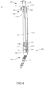
FIG. 4 is a perspective view of a first step of the assembly of the components of one embodiment of a surgical system in accordance with the principles of the present disclosure; -
FIG. 5 is a perspective view of a second step of the assembly of the components of one embodiment of a surgical system in accordance with the principles of the present disclosure; and -
FIG. 6 is a perspective view of a third step of the assembly of the components of one embodiment of a surgical system in accordance with the principles of the present disclosure. - The exemplary embodiments of the surgical system disclosed are discussed in terms of medical devices for the treatment of musculoskeletal disorders and more particularly, in terms of a spinal implant system. Associated methods are also described herein to aid understanding of the invention, but these do not form part of the claimed invention. Furthermore, illustrative methods of use and treatments are discussed to further the understanding of the inventive implant support cap and the inventive spinal implant system. In some embodiments, the systems of the present disclosure comprise medical devices including surgical instruments and implants that can be employed with a surgical treatment, as described herein, for example, with a cervical, thoracic, lumbar and/or sacral region of a spine.
- In some embodiments, the present surgical system comprises a surgical instrument, such as, for example, an extender cap configured to guide and/or align one or more components of an implant support, implant and/or spinal construct into engagement for connection and/or assembly of the components. In some embodiments, the surgical instrument includes a guide to align the implant support, for example, at least one extender tab with at least one longitudinal passageway for connection with the extender cap. In some embodiments, the guide includes at least one opening disposed in communication with the at least one passageway to facilitate connection with the implant support. The guide includes an angled surface configured to facilitate disposal of the extender tabs with the extender cap.
- In some embodiments, the surgical instrument includes a guide engageable with at least one extender tab to guide and/or align the at least one extender tab into the at least one passageway, for example, axial slots. In some embodiments, the slots are configured to dispose the extender tabs with a cavity of the extender cap.
- In some embodiments, the extender tabs are configured for aligning an implant, such as, for example, a bone fastener, with various instruments and providing an access path for set screws and rods. In some embodiments, the extender tabs are connectable with the bone fastener.
- The surgical system of the present disclosure may be employed to treat spinal disorders such as, for example, degenerative disc disease, disc herniation, osteoporosis, spondylolisthesis, stenosis, scoliosis and other curvature abnormalities, kyphosis, tumor and The surgical system of the present disclosure may be employed with other osteal and bone related applications, including those associated with diagnostics and therapeutics. The disclosed surgical system may be alternatively employed in a surgical treatment with a patient in a prone or supine position, and/or employ various surgical approaches to the spine, including anterior, posterior, posterior mid-line, direct lateral, postero-lateral, and/or antero-lateral approaches, and in other body regions. The surgical system of the present disclosure may also be alternatively employed with procedures for treating the lumbar, cervical, thoracic, sacral and pelvic regions of a spinal column. The surgical system of the present disclosure may also be used on animals, bone models and other non-living substrates, such as, for example, in training, testing and demonstration.
- The surgical system of the present disclosure may be understood more readily by reference to the following detailed description of the embodiments taken in connection with the accompanying drawing figures, which form a part of this disclosure. References to "embodiments" throughout the description which are not under the scope of the appended claims merely represent possible exemplary executions and are therefore not part of the present invention. In some embodiments, as used in the specification and including the appended claims, the singular forms "a," "an," and "the" include the plural, and reference to a particular numerical value includes at least that particular value, unless the context clearly dictates otherwise. Ranges may be expressed herein as from "about" or "approximately" one particular value and/or to "about" or "approximately" another particular value. When such a range is expressed, another embodiment includes from the one particular value and/or to the other particular value. Similarly, when values are expressed as approximations, by use of the antecedent "about," it will be understood that the particular value forms another embodiment. It is also understood that all spatial references, such as, for example, horizontal, vertical, top, upper, lower, bottom, left and right, are for illustrative purposes only and can be varied within the scope of the disclosure. For example, the references "upper" and "lower" are relative and used only in the context to the other, and are not necessarily "superior" and "inferior."
- As used in the specification and including the appended claims, "treating" or "treatment" of a disease or condition refers to performing a procedure that may include administering one or more drugs to a patient (human, normal or otherwise or other mammal), employing implantable devices, and/or employing instruments that treat the disease, such as, for example, microdiscectomy instruments used to remove portions of bulging or herniated discs and/or bone spurs, in an effort to alleviate signs or symptoms of the disease or condition. Alleviation can occur prior to signs or symptoms of the disease or condition appearing, as well as after their appearance. Thus, treating or treatment includes preventing or prevention of disease or undesirable condition (e.g., preventing the disease from occurring in a patient, who may be predisposed to the disease but has not yet been diagnosed as having it). In addition, treating or treatment does not require complete alleviation of signs or symptoms, does not require a cure, and specifically includes procedures that have only a marginal effect on the patient. Treatment can include inhibiting the disease, e.g., arresting its development, or relieving the disease, e.g., causing regression of the disease. For example, treatment can include reducing acute or chronic inflammation; alleviating pain and mitigating and inducing re-growth of new ligament, bone and other tissues; as an adjunct in surgery; and/or any repair procedure. In some embodiments, as used in the specification and including the appended claims, the term "tissue" includes soft tissue, ligaments, tendons, cartilage and/or bone unless specifically referred to otherwise.
- The following discussion includes a description of a surgical system including a surgical instrument, related components and illustrative methods of employing the surgical system. Alternate embodiments are also disclosed. Reference is made in detail to the exemplary embodiments of the present disclosure, which are illustrated in the accompanying figures. Turning to
FIGS. 1-6 , there are illustrated components of a surgical system, such as, for example, aspinal implant system 10. An embodiment ofsystem 10 is shown inFIGs. 4-6 .FIGS. 1-3 show a few components of the system. - The components of
spinal implant system 10 can be fabricated from biologically acceptable materials suitable for medical applications, including metals, synthetic polymers, ceramics and bone material and/or their composites. For example, the components of spinal implant system 10, individually or collectively, can be fabricated from materials such as stainless steel alloys, aluminum, commercially pure titanium, titanium alloys, Grade 5 titanium, super-elastic titanium alloys, cobalt-chrome alloys, superelastic metallic alloys (e.g., Nitinol, super elasto-plastic metals, such as GUM METAL®), ceramics and composites thereof such as calcium phosphate (e.g., SKELITE™), thermoplastics such as polyaryletherketone (PAEK) including polyetheretherketone (PEEK), polyetherketoneketone (PEKK) and polyetherketone (PEK), carbon-PEEK composites, PEEK-BaSO4 polymeric rubbers, polyethylene terephthalate (PET), fabric, silicone, polyurethane, silicone-polyurethane copolymers, polymeric rubbers, polyolefin rubbers, hydrogels, semi-rigid and rigid materials, elastomers, rubbers, thermoplastic elastomers, thermoset elastomers, elastomeric composites, rigid polymers including polyphenylene, polyamide, polyimide, polyetherimide, polyethylene, epoxy, bone material including autograft, allograft, xenograft or transgenic cortical and/or corticocancellous bone, and tissue growth or differentiation factors, partially resorbable materials, such as, for example, composites of metals and calcium-based ceramics, composites of PEEK and calcium based ceramics, composites of PEEK with resorbable polymers, totally resorbable materials, such as, for example, calcium based ceramics such as calcium phosphate, tri-calcium phosphate (TCP), hydroxyapatite (HA)-TCP, calcium sulfate, or other resorbable polymers such as polyaetide, polyglycolide, polytyrosine carbonate, polycaroplaetohe and their combinations. - Various components of
spinal implant system 10 may have material composites, including the above materials, to achieve various desired characteristics such as strength, rigidity, elasticity, compliance, biomechanical performance, durability and radiolucency for imaging preference. The components ofspinal implant system 10, individually or collectively, may also be fabricated from a heterogeneous material such as a combination of two or more of the above-described materials. The components ofspinal implant system 10 may be monolithically formed, integrally connected or include fastening elements and/or instruments, as described herein. -
Spinal implant system 10 is employed, for example, with a fully open surgical procedure, a minimally invasive procedure including percutaneous techniques, and mini-open surgical techniques to deliver and introduce instrumentation and/or a spinal implant, such as, for example, a bone fastener, at a surgical site of a patient, which includes, for example, a spine. In some embodiments, the spinal implant can include one or more components of one or more spinal constructs, such as, for example, interbody devices, interbody cages, bone fasteners, spinal rods, tethers, connectors, plates and/or bone graft, and can be employed with various surgical procedures including surgical treatment of a cervical, thoracic, lumbar and/or sacral region of a spine. -
Spinal implant system 10 includes an implant support cap, for example, anextender cap 12.Cap 12 is configured to guide and/or align an implant support member, such as, for example,extender tabs cap 12 for connection and/or assembly of the components of an extender connected to abone fastener assembly 150.Cap 12 comprises aguide 40 configured to facilitate connection ofextender tabs cap 12. -
Cap 12 extends between anend 14 and anend 16 defining an axis X1.Cap 12 includes awall 24.Wall 24 includesportions Wall 24 includes aninner surface 26 extending alongportions Surface 26 defines acavity 28 configured for disposal ofextender tabs Cavity 28 includes a substantially rectangular configuration. In some embodiments,cavity 28 has various configurations including, for example, round, oval, polygonal, irregular, consistent, variable, uniform and non-uniform. -
Portions corners 30 along the inner surface ofwall 24. In some embodiments, the inner surfaces ofportions surface forming corners 30, as shown by way of example inFIG. 3 . In some embodiments,corners 30 may have various configurations including, for example, irregular, consistent, variable, uniform and non-uniform.Corners 30 extend axially alongwall 24. In some embodiments,corners 30 extend at alternate orientations alongwall 24, such as, for example, at transverse, perpendicular and/or other angular orientations such as acute or obtuse, and/or may be offset or staggered, with respect to axis X1. - A
projection 34 is disposed withportions FIG. 3 .Projection 34 is configured toabut extender tabs extender tabs cavity 28. For example, asextender tabs cap 12,projection 34 resists and/or preventsextender tabs cavity 28 during insertion. -
Portion 24a includes asurface 41 connectable with a portion ofextender tabs spring tip 178 or aspring tip 176, as described herein.Surface 41 defines at least one groove, such as, for example, apocket 42, as shown inFIG. 1 .Portion 24a includes a pair ofpockets 42.Pockets 42 are configured for a mating engagement withspring tips 178, as described herein.Surface 41 is configured as alock 44 to resist and/or prevent disengagement ofspring tips 178 frompocket 42, as described herein. - Portion 24c includes a
surface 50, similar tosurface 41, connectable with a portion ofextender tabs spring tip 178 orspring tip 176, as described herein.Surface 50 defines at least one groove, such as, for example, apocket 52, as shown inFIG. 2 . Portion 24c includes a pair ofpockets 52, as shown inFIG. 2 .Pockets 52 are configured for a mating engagement withspring tips 176, as described herein.Pockets 52 are disposed in alignment withpockets 42, as shown inFIG. 1 , to facilitate engagement ofspring tips 176.Surface 50 is configured as alock 54 to resist and/or prevent disengagement ofspring tips 176 frompocket 52, as described herein. -
Pockets spring tips FIG. 6 . Disposal ofspring tips pockets extender tabs cap 12. In some embodiments, pockets 42, 52 are disposed parallel to axis X1. In some embodiments, pockets 42, 52 are disposed at alternate orientations relative to axis a, such as, for example, at transverse, perpendicular and/or other angular orientations such as acute or obtuse, and/or may be offset or staggered. In some embodiments, locks 44, 54 are configured to provide audible and/or tactile indicia, such as, for example, an audible click indicating engagement ofspring tips cap 12. -
Wall 24 includeslongitudinal rails Rail 60a includessurface 64.Rail 60b includes asurface 66.Surfaces axial slot 68.Slot 68 extends along axis X1.Slot 68 is configured to facilitate engagement ofextender tab 152 withcap 12, as described herein. In some embodiments, all or only a portion ofsurfaces Surfaces extender tab 152 intocavity 28. -
Rail 60c includessurface 70.Rail 60d includes asurface 72.Surfaces axial slot 74.Slot 74 extends along axis X1.Slot 74 is configured to facilitate engagement ofextender tab 152a withcap 12, as described herein. In some embodiments, all or only a portion ofsurfaces Surfaces extender tab 152a intocavity 28. -
Extender tabs slots extender tabs cavity 28 and into locking engagement withcap 12, as described herein.Slots extender tabs spring tips pockets -
Guide 40 is configured to guide and/ordirect extender tabs cavity 28.Guide 40 includes adistal surface 80 ofwall 24 and anextension 82 extending from portion 24c, as shown inFIG. 2 .Surface 80 includes anopening 84 disposed in communication withslot 68.Surface 80 includes anopening 86 disposed in communication withslot 74.Surface 80 is configured to guide and/ordirect extender tabs slots -
Surface 80 is disposed at an angle relative to axis X1 such thatsurface 80 is disposed in a transverse orientation relative toslots ramp 81, as shown inFIGS. 2 and3 .Ramp 81 is selectively inclined to facilitate translation and/or guiding ofextender tabs slots slots surface 80 is disposed at alternate orientations relative to axis X1, such as, for example, at transverse, perpendicular and/or other angular orientations such as acute or obtuse, and/or may be offset or staggered. In some embodiments,surface 80 is selectively inclined to facilitate translation and/or disengagement ofextender tabs cap 12. -
Extension 82 includes aslot 92 and aslot 94. Slot 90 is disposed coaxially withslot 68, as shown inFIG. 1 .Slot 92 is disposed coaxially withslot 74.Extender tabs slots 90, 92 intoslots extender tabs cap 12. -
Bone fastener assembly 150 includes abone fastener 100.Bone fastener 100 includes areceiver 102.Receiver 102 is connected to extendertabs Receiver 102 includes a pair of spaced apartarms Receiver 102 includes a socket configured for engagement with a surgical instrument.Receiver 102 includes an inner surface having a thread form locatedadjacent arm 104 and a thread form locatedadjacent arm 106. The thread forms ofarms Bone fastener 100 includes a threadedshaft 116.Shaft 116 is configured to penetrate tissue, such as, for example, bone. -
Arm 104 includes a break awaytab 120 that is frangibly connected to arm 104 such that manipulation oftab 120 relative to arm 104 can fracture andseparate tab 120 fromarm 104 at a predetermined force and/or torque limit, as described herein.Arm 106 includes a break awaytab 130 that is frangibly connected to arm 106 such that manipulation oftab 130 relative to arm 106 can fracture andseparate tab 130 fromarm 106 at a predetermined force and/or torque limit, as described herein. In some embodiments, as force and/or torque is applied totabs - In some embodiments,
tabs tabs arms tabs -
Bone fastener assembly 150 includesextender tabs bone fastener 100.Extender tabs proximal end 172 and adistal end 174.Proximal end 172 includesspring tips FIG. 4 .Spring tips pockets cap 12 to resist and/or prevent disengagement ofspring tips bone fastener 100, such as, for example,tabs tabs fix extender tabs bone fastener 100. - In assembly, operation and use,
spinal implant system 10, similar to the systems described herein, is employed with a surgical procedure, such as, for example, a treatment of an applicable condition or injury of an affected section of a spinal column and adjacent areas within a body. In such treatments, one or all of the components ofspinal implant system 10 can be delivered or utilized as a pre-assembled device or can be assembled in situ.Spinal implant system 10 may be completely or partially revised, removed or replaced. - In use, to treat vertebrae (not shown), a medical practitioner obtains access to a surgical site in any appropriate manner, such as through incision and retraction of tissues. The inventive
spinal implant system 10 can be used in any existing surgical method or technique including open surgery, mini-open surgery, minimally invasive surgery and percutaneous surgical implantation, whereby the vertebrae is accessed through a mini-incision, or sleeve that provides a protected passageway to the area. Once access to the surgical site is obtained, the particular surgical procedure can be performed for treating the spine disorder. - An incision is made in the body of a patient and a cutting instrument (not shown) creates a surgical pathway for implantation of components of
spinal implant system 10. A preparation instrument (not shown) can be employed to prepare tissue surfaces of the vertebrae as well as for aspiration and irrigation of a surgical region. - Pilot holes (not shown) are made in selected levels of vertebrae for receiving
shafts 116 ofbone fastener assemblies 150. A surgical instrument, such as, for example, a driver is connected tobone fastener 100 andbone fasteners 100 are engaged with vertebrae.Extender tabs bone fasteners 100, as described herein. -
Extender tabs adjacent cap 12, as shown inFIG. 4 .Extender tabs guide 40 such thatramp 81 directsextender tabs slots extension 82.Extender tabs slots Slots extender tabs openings slots -
Extender tabs slots extension 82 such thatextender tabs slots Slots extender tabs openings slots Ramp 81 facilitates directing and/or aligningextender tabs slots extension 82. -
Surfaces slot 68 and surfaces 70, 72 ofslot 74 are configured to causeextender tabs pockets FIG. 6 . In some embodiments,spring tips surfaces spring tips cap 12.Projection 34 resists and/or prevents disengagement ofcap 12 fromcavity 28 during insertion ofextender tabs - A surgical procedure using an inventive spinal implant system can include delivering a spinal rod along the surgical pathway for connection with one or
more bone fasteners 100. A reduction instrument (not shown) engages the spinal rod for reduction withreceivers 102 and fixed thereto. In some embodiments, a tab breaker is engaged withextender tabs tabs tabs extender tabs tabs bone fasteners 100. - Upon completion of a procedure the surgical instruments, assemblies and non-implanted components of
spinal implant system 10 can be removed and the incision(s) can be closed. One or more of the components ofspinal implant system 10 can be made of radiolucent materials such as polymers. Radiomarkers may be included for identification under x-ray, fluoroscopy, CT or other imaging techniques. In some embodiments,spinal implant system 10 may include one or a plurality of spinal rods, plates, connectors and/or bone fasteners for use with a single vertebral level or a plurality of vertebral levels. - One or more bone fasteners, as described herein, may be engaged with tissue in various orientations, such as, for example, series, parallel, offset, staggered and/or alternate vertebral levels. In some embodiments, the bone fasteners may comprise multi-axial screws, sagittal adjusting screws, pedicle screws, mono-axial screws, uniplanar screws, facet screws, fixed screws, tissue penetrating screws, conventional screws, expanding screws, wedges, anchors, buttons, clips, snaps, friction fittings, compressive fittings, expanding rivets, staples, nails, adhesives, posts, fixation plates and/or posts.
- In one embodiment,
spinal implant system 10 includes an agent, which may be disposed, packed, coated or layered within, on or about the components and/or surfaces ofspinal implant system 10. In some embodiments, the agent may include bone growth promoting material, such as, for example, bone graft to enhance fixation of the components and/or surfaces ofspinal implant system 10 with vertebrae. In some embodiments, the agent may include one or a plurality of therapeutic agents and/or pharmacological agents for release, including sustained release, to treat, for example, pain, inflammation and degeneration.
Claims (4)
- An implant support cap (12) extending along a longitudinal axis (X1) between ends (14, 16) of the implant support cap (12), and comprising:a wall (24) defining a cavity (28) and including mating grooves (42), the mating grooves (42) defining a first longitudinal passageway (68) and a second longitudinal passageway (74),characterized in that the implant support cap (12) further comprises:a guide (40) including an angled distal surface (80) of wall (24), engageable with an implant support member including spaced apart extender tabs (152, 152a), the guide (40) further including an extension (82) having a first slot (92) disposed coaxial with the first passageway (68) and a second slot (94) disposed coaxial with the second passageway (74), the angled distal surface (80) including a first opening (84) communicating with the first passageway (68) and a second opening (86) communicating with the second passageway (74) to orient the tabs (152, 152a) with the passageways (68, 74) such that the implant support member is connectable with the wall (24),wherein the angled distal surface (80) is disposed at an angle relative to the longitudinal axis (X1) such that surface (80) is disposed in a transverse orientation relative to the passageways (68, 74) to define a ramp (81), wherein the guide (40), along the ramp (81), is open in a transverse direction to the longitudinal axis (X1), thereby exposing the first slot (92) and the second slot (94) in the transverse direction to the longitudinal axis (X1).
- An implant support cap (12) as recited in Claim 1, wherein the wall (24) and the tabs (152, 152a) are engageable in a snap-fit assembly.
- An implant support cap (12) as recited in Claim 1, wherein the wall (24) includes a lock (44, 54) being releasably engageable with the tabs (152, 152a).
- A spinal implant system (10) comprising:an implant support cap (12) according to any of claims 1 to 3;an implant support member including spaced apart extender tabs (152, 152a) engageable with the distal surface (80) in a configuration to guide the tabs (152, 152a) into the passageways (68, 74) such that the implant support member is connectable with the cap (12); andan implant receiver (102) connected to the tabs (152, 152a).
Applications Claiming Priority (2)
| Application Number | Priority Date | Filing Date | Title |
|---|---|---|---|
| US16/383,742 US11278431B2 (en) | 2019-04-15 | 2019-04-15 | Spinal implant system and method |
| PCT/US2019/056683 WO2020214205A1 (en) | 2019-04-15 | 2019-10-17 | Spinal implant system and method |
Publications (3)
| Publication Number | Publication Date |
|---|---|
| EP3955838A1 EP3955838A1 (en) | 2022-02-23 |
| EP3955838A4 EP3955838A4 (en) | 2023-05-24 |
| EP3955838B1 true EP3955838B1 (en) | 2025-04-23 |
Family
ID=72747579
Family Applications (1)
| Application Number | Title | Priority Date | Filing Date |
|---|---|---|---|
| EP19925196.8A Active EP3955838B1 (en) | 2019-04-15 | 2019-10-17 | Spinal implant system |
Country Status (4)
| Country | Link |
|---|---|
| US (1) | US11278431B2 (en) |
| EP (1) | EP3955838B1 (en) |
| CN (1) | CN113677279B (en) |
| WO (1) | WO2020214205A1 (en) |
Families Citing this family (2)
| Publication number | Priority date | Publication date | Assignee | Title |
|---|---|---|---|---|
| US11134994B2 (en) * | 2020-01-30 | 2021-10-05 | Warsaw Orthopedic, Inc. | Spinal-correction system having threaded extender tabs and reduction tab extenders |
| EP4008284B1 (en) | 2020-12-02 | 2024-10-23 | Biedermann Technologies GmbH & Co. KG | Connection device for use with extension members of a bone anchor |
Family Cites Families (9)
| Publication number | Priority date | Publication date | Assignee | Title |
|---|---|---|---|---|
| US7666189B2 (en) | 2004-09-29 | 2010-02-23 | Synthes Usa, Llc | Less invasive surgical system and methods |
| GB0623801D0 (en) * | 2006-11-29 | 2007-01-10 | Surgicraft Ltd | Orthopaedic implants and prosthesis |
| US8496661B2 (en) * | 2008-11-03 | 2013-07-30 | Omni Surgical LLC | System and method for micro-invasive transfacet lumbar interbody fusion |
| US8545505B2 (en) * | 2010-01-15 | 2013-10-01 | Pioneer Surgical Technology, Inc. | Low friction rod persuader |
| US8535318B2 (en) | 2010-04-23 | 2013-09-17 | DePuy Synthes Products, LLC | Minimally invasive instrument set, devices and related methods |
| US9289250B2 (en) | 2011-10-17 | 2016-03-22 | Warsaw Orthopedic, Inc. | Extender collar system |
| US9220539B2 (en) * | 2012-03-19 | 2015-12-29 | Warsaw Orthopedic, Inc. | Spinal implant system and method |
| JP6290002B2 (en) | 2013-06-07 | 2018-03-07 | 賢 石井 | Spinal fixation device |
| US9895235B2 (en) * | 2015-12-18 | 2018-02-20 | Warsaw Orthopedic, Inc. | Spinal implant system and method |
-
2019
- 2019-04-15 US US16/383,742 patent/US11278431B2/en active Active
- 2019-10-17 EP EP19925196.8A patent/EP3955838B1/en active Active
- 2019-10-17 WO PCT/US2019/056683 patent/WO2020214205A1/en not_active Ceased
- 2019-10-17 CN CN201980095363.9A patent/CN113677279B/en active Active
Also Published As
| Publication number | Publication date |
|---|---|
| EP3955838A1 (en) | 2022-02-23 |
| CN113677279B (en) | 2024-12-17 |
| US11278431B2 (en) | 2022-03-22 |
| WO2020214205A1 (en) | 2020-10-22 |
| US20200323652A1 (en) | 2020-10-15 |
| EP3955838A4 (en) | 2023-05-24 |
| CN113677279A (en) | 2021-11-19 |
Similar Documents
| Publication | Publication Date | Title |
|---|---|---|
| US11998243B2 (en) | Spinal implant system and method | |
| US9220539B2 (en) | Spinal implant system and method | |
| US9375240B2 (en) | Spinal implant system and method | |
| EP3366242B1 (en) | Spinal implant system | |
| US20250331896A1 (en) | Surgical system and method | |
| US12274430B2 (en) | Surgical system and method | |
| US20200030015A1 (en) | Spinal implant system and method | |
| US20180153708A1 (en) | Spinal implant system and method | |
| US20150045834A1 (en) | Spinal implant system | |
| EP3958766B1 (en) | Spinal implant system | |
| US11679003B2 (en) | Surgical implant system and method | |
| US11278431B2 (en) | Spinal implant system and method | |
| US11026733B2 (en) | Surgical system and method | |
| EP4285848A1 (en) | Spinal implant system | |
| US11602381B2 (en) | Spinal implant system and method | |
| US12171468B2 (en) | Spinal implant system and method | |
| EP4282357A1 (en) | Spinal implant system | |
| US20180116697A1 (en) | Spinal implant system and method |
Legal Events
| Date | Code | Title | Description |
|---|---|---|---|
| STAA | Information on the status of an ep patent application or granted ep patent |
Free format text: STATUS: THE INTERNATIONAL PUBLICATION HAS BEEN MADE |
|
| PUAI | Public reference made under article 153(3) epc to a published international application that has entered the european phase |
Free format text: ORIGINAL CODE: 0009012 |
|
| STAA | Information on the status of an ep patent application or granted ep patent |
Free format text: STATUS: REQUEST FOR EXAMINATION WAS MADE |
|
| 17P | Request for examination filed |
Effective date: 20211109 |
|
| AK | Designated contracting states |
Kind code of ref document: A1 Designated state(s): AL AT BE BG CH CY CZ DE DK EE ES FI FR GB GR HR HU IE IS IT LI LT LU LV MC MK MT NL NO PL PT RO RS SE SI SK SM TR |
|
| DAV | Request for validation of the european patent (deleted) | ||
| DAX | Request for extension of the european patent (deleted) | ||
| A4 | Supplementary search report drawn up and despatched |
Effective date: 20230424 |
|
| RIC1 | Information provided on ipc code assigned before grant |
Ipc: A61B 17/86 20060101ALI20230418BHEP Ipc: A61B 17/70 20060101AFI20230418BHEP |
|
| GRAP | Despatch of communication of intention to grant a patent |
Free format text: ORIGINAL CODE: EPIDOSNIGR1 |
|
| STAA | Information on the status of an ep patent application or granted ep patent |
Free format text: STATUS: GRANT OF PATENT IS INTENDED |
|
| INTG | Intention to grant announced |
Effective date: 20240808 |
|
| GRAJ | Information related to disapproval of communication of intention to grant by the applicant or resumption of examination proceedings by the epo deleted |
Free format text: ORIGINAL CODE: EPIDOSDIGR1 |
|
| STAA | Information on the status of an ep patent application or granted ep patent |
Free format text: STATUS: REQUEST FOR EXAMINATION WAS MADE |
|
| GRAP | Despatch of communication of intention to grant a patent |
Free format text: ORIGINAL CODE: EPIDOSNIGR1 |
|
| STAA | Information on the status of an ep patent application or granted ep patent |
Free format text: STATUS: GRANT OF PATENT IS INTENDED |
|
| INTC | Intention to grant announced (deleted) | ||
| INTG | Intention to grant announced |
Effective date: 20241115 |
|
| GRAS | Grant fee paid |
Free format text: ORIGINAL CODE: EPIDOSNIGR3 |
|
| GRAA | (expected) grant |
Free format text: ORIGINAL CODE: 0009210 |
|
| STAA | Information on the status of an ep patent application or granted ep patent |
Free format text: STATUS: THE PATENT HAS BEEN GRANTED |
|
| AK | Designated contracting states |
Kind code of ref document: B1 Designated state(s): AL AT BE BG CH CY CZ DE DK EE ES FI FR GB GR HR HU IE IS IT LI LT LU LV MC MK MT NL NO PL PT RO RS SE SI SK SM TR |
|
| REG | Reference to a national code |
Ref country code: GB Ref legal event code: FG4D |
|
| REG | Reference to a national code |
Ref country code: CH Ref legal event code: EP |
|
| REG | Reference to a national code |
Ref country code: DE Ref legal event code: R096 Ref document number: 602019069186 Country of ref document: DE |
|
| REG | Reference to a national code |
Ref country code: IE Ref legal event code: FG4D |
|
| REG | Reference to a national code |
Ref country code: NL Ref legal event code: MP Effective date: 20250423 |
|
| PG25 | Lapsed in a contracting state [announced via postgrant information from national office to epo] |
Ref country code: NL Free format text: LAPSE BECAUSE OF FAILURE TO SUBMIT A TRANSLATION OF THE DESCRIPTION OR TO PAY THE FEE WITHIN THE PRESCRIBED TIME-LIMIT Effective date: 20250423 |
|
| REG | Reference to a national code |
Ref country code: AT Ref legal event code: MK05 Ref document number: 1787025 Country of ref document: AT Kind code of ref document: T Effective date: 20250423 |
|
| PG25 | Lapsed in a contracting state [announced via postgrant information from national office to epo] |
Ref country code: PT Free format text: LAPSE BECAUSE OF FAILURE TO SUBMIT A TRANSLATION OF THE DESCRIPTION OR TO PAY THE FEE WITHIN THE PRESCRIBED TIME-LIMIT Effective date: 20250825 Ref country code: ES Free format text: LAPSE BECAUSE OF FAILURE TO SUBMIT A TRANSLATION OF THE DESCRIPTION OR TO PAY THE FEE WITHIN THE PRESCRIBED TIME-LIMIT Effective date: 20250423 Ref country code: FI Free format text: LAPSE BECAUSE OF FAILURE TO SUBMIT A TRANSLATION OF THE DESCRIPTION OR TO PAY THE FEE WITHIN THE PRESCRIBED TIME-LIMIT Effective date: 20250423 |
|
| REG | Reference to a national code |
Ref country code: LT Ref legal event code: MG9D |
|
| PG25 | Lapsed in a contracting state [announced via postgrant information from national office to epo] |
Ref country code: GR Free format text: LAPSE BECAUSE OF FAILURE TO SUBMIT A TRANSLATION OF THE DESCRIPTION OR TO PAY THE FEE WITHIN THE PRESCRIBED TIME-LIMIT Effective date: 20250724 Ref country code: NO Free format text: LAPSE BECAUSE OF FAILURE TO SUBMIT A TRANSLATION OF THE DESCRIPTION OR TO PAY THE FEE WITHIN THE PRESCRIBED TIME-LIMIT Effective date: 20250723 |
|
| PG25 | Lapsed in a contracting state [announced via postgrant information from national office to epo] |
Ref country code: PL Free format text: LAPSE BECAUSE OF FAILURE TO SUBMIT A TRANSLATION OF THE DESCRIPTION OR TO PAY THE FEE WITHIN THE PRESCRIBED TIME-LIMIT Effective date: 20250423 |
|
| PG25 | Lapsed in a contracting state [announced via postgrant information from national office to epo] |
Ref country code: BG Free format text: LAPSE BECAUSE OF FAILURE TO SUBMIT A TRANSLATION OF THE DESCRIPTION OR TO PAY THE FEE WITHIN THE PRESCRIBED TIME-LIMIT Effective date: 20250423 |
|
| PG25 | Lapsed in a contracting state [announced via postgrant information from national office to epo] |
Ref country code: HR Free format text: LAPSE BECAUSE OF FAILURE TO SUBMIT A TRANSLATION OF THE DESCRIPTION OR TO PAY THE FEE WITHIN THE PRESCRIBED TIME-LIMIT Effective date: 20250423 |
|
| PG25 | Lapsed in a contracting state [announced via postgrant information from national office to epo] |
Ref country code: AT Free format text: LAPSE BECAUSE OF FAILURE TO SUBMIT A TRANSLATION OF THE DESCRIPTION OR TO PAY THE FEE WITHIN THE PRESCRIBED TIME-LIMIT Effective date: 20250423 |
|
| PGFP | Annual fee paid to national office [announced via postgrant information from national office to epo] |
Ref country code: FR Payment date: 20250925 Year of fee payment: 7 |
|
| PG25 | Lapsed in a contracting state [announced via postgrant information from national office to epo] |
Ref country code: RS Free format text: LAPSE BECAUSE OF FAILURE TO SUBMIT A TRANSLATION OF THE DESCRIPTION OR TO PAY THE FEE WITHIN THE PRESCRIBED TIME-LIMIT Effective date: 20250723 |
|
| PG25 | Lapsed in a contracting state [announced via postgrant information from national office to epo] |
Ref country code: IS Free format text: LAPSE BECAUSE OF FAILURE TO SUBMIT A TRANSLATION OF THE DESCRIPTION OR TO PAY THE FEE WITHIN THE PRESCRIBED TIME-LIMIT Effective date: 20250823 |
|
| PG25 | Lapsed in a contracting state [announced via postgrant information from national office to epo] |
Ref country code: LV Free format text: LAPSE BECAUSE OF FAILURE TO SUBMIT A TRANSLATION OF THE DESCRIPTION OR TO PAY THE FEE WITHIN THE PRESCRIBED TIME-LIMIT Effective date: 20250423 |
|
| PGFP | Annual fee paid to national office [announced via postgrant information from national office to epo] |
Ref country code: DE Payment date: 20250923 Year of fee payment: 7 |
|
| PG25 | Lapsed in a contracting state [announced via postgrant information from national office to epo] |
Ref country code: SM Free format text: LAPSE BECAUSE OF FAILURE TO SUBMIT A TRANSLATION OF THE DESCRIPTION OR TO PAY THE FEE WITHIN THE PRESCRIBED TIME-LIMIT Effective date: 20250423 Ref country code: DK Free format text: LAPSE BECAUSE OF FAILURE TO SUBMIT A TRANSLATION OF THE DESCRIPTION OR TO PAY THE FEE WITHIN THE PRESCRIBED TIME-LIMIT Effective date: 20250423 |
|
| PG25 | Lapsed in a contracting state [announced via postgrant information from national office to epo] |
Ref country code: CZ Free format text: LAPSE BECAUSE OF FAILURE TO SUBMIT A TRANSLATION OF THE DESCRIPTION OR TO PAY THE FEE WITHIN THE PRESCRIBED TIME-LIMIT Effective date: 20250423 |
|
| PG25 | Lapsed in a contracting state [announced via postgrant information from national office to epo] |
Ref country code: EE Free format text: LAPSE BECAUSE OF FAILURE TO SUBMIT A TRANSLATION OF THE DESCRIPTION OR TO PAY THE FEE WITHIN THE PRESCRIBED TIME-LIMIT Effective date: 20250423 |
|
| REG | Reference to a national code |
Ref country code: DE Ref legal event code: R097 Ref document number: 602019069186 Country of ref document: DE |
|
| PG25 | Lapsed in a contracting state [announced via postgrant information from national office to epo] |
Ref country code: RO Free format text: LAPSE BECAUSE OF FAILURE TO SUBMIT A TRANSLATION OF THE DESCRIPTION OR TO PAY THE FEE WITHIN THE PRESCRIBED TIME-LIMIT Effective date: 20250423 Ref country code: SK Free format text: LAPSE BECAUSE OF FAILURE TO SUBMIT A TRANSLATION OF THE DESCRIPTION OR TO PAY THE FEE WITHIN THE PRESCRIBED TIME-LIMIT Effective date: 20250423 |
|
| PG25 | Lapsed in a contracting state [announced via postgrant information from national office to epo] |
Ref country code: IT Free format text: LAPSE BECAUSE OF FAILURE TO SUBMIT A TRANSLATION OF THE DESCRIPTION OR TO PAY THE FEE WITHIN THE PRESCRIBED TIME-LIMIT Effective date: 20250423 |
|
| PLBE | No opposition filed within time limit |
Free format text: ORIGINAL CODE: 0009261 |
|
| STAA | Information on the status of an ep patent application or granted ep patent |
Free format text: STATUS: NO OPPOSITION FILED WITHIN TIME LIMIT |
|
| REG | Reference to a national code |
Ref country code: CH Ref legal event code: L10 Free format text: ST27 STATUS EVENT CODE: U-0-0-L10-L00 (AS PROVIDED BY THE NATIONAL OFFICE) Effective date: 20260304 |
|
| 26N | No opposition filed |
Effective date: 20260126 |