EP3955470B1 - Method for enabling efficient mimo processing for o-ran fronthaul interface in cloud ran systems - Google Patents
Method for enabling efficient mimo processing for o-ran fronthaul interface in cloud ran systems Download PDFInfo
- Publication number
- EP3955470B1 EP3955470B1 EP21186189.3A EP21186189A EP3955470B1 EP 3955470 B1 EP3955470 B1 EP 3955470B1 EP 21186189 A EP21186189 A EP 21186189A EP 3955470 B1 EP3955470 B1 EP 3955470B1
- Authority
- EP
- European Patent Office
- Prior art keywords
- codebook
- matrix
- ran
- dmrs
- combiner
- Prior art date
- Legal status (The legal status is an assumption and is not a legal conclusion. Google has not performed a legal analysis and makes no representation as to the accuracy of the status listed.)
- Active
Links
Images



Classifications
-
- H—ELECTRICITY
- H04—ELECTRIC COMMUNICATION TECHNIQUE
- H04B—TRANSMISSION
- H04B7/00—Radio transmission systems, i.e. using radiation field
- H04B7/02—Diversity systems; Multi-antenna system, i.e. transmission or reception using multiple antennas
- H04B7/04—Diversity systems; Multi-antenna system, i.e. transmission or reception using multiple antennas using two or more spaced independent antennas
- H04B7/0413—MIMO systems
- H04B7/0456—Selection of precoding matrices or codebooks, e.g. using matrices antenna weighting
-
- H—ELECTRICITY
- H04—ELECTRIC COMMUNICATION TECHNIQUE
- H04B—TRANSMISSION
- H04B7/00—Radio transmission systems, i.e. using radiation field
- H04B7/02—Diversity systems; Multi-antenna system, i.e. transmission or reception using multiple antennas
- H04B7/04—Diversity systems; Multi-antenna system, i.e. transmission or reception using multiple antennas using two or more spaced independent antennas
- H04B7/06—Diversity systems; Multi-antenna system, i.e. transmission or reception using multiple antennas using two or more spaced independent antennas at the transmitting station
- H04B7/0613—Diversity systems; Multi-antenna system, i.e. transmission or reception using multiple antennas using two or more spaced independent antennas at the transmitting station using simultaneous transmission
- H04B7/0615—Diversity systems; Multi-antenna system, i.e. transmission or reception using multiple antennas using two or more spaced independent antennas at the transmitting station using simultaneous transmission of weighted versions of same signal
- H04B7/0617—Diversity systems; Multi-antenna system, i.e. transmission or reception using multiple antennas using two or more spaced independent antennas at the transmitting station using simultaneous transmission of weighted versions of same signal for beam forming
-
- H—ELECTRICITY
- H04—ELECTRIC COMMUNICATION TECHNIQUE
- H04B—TRANSMISSION
- H04B7/00—Radio transmission systems, i.e. using radiation field
- H04B7/02—Diversity systems; Multi-antenna system, i.e. transmission or reception using multiple antennas
- H04B7/04—Diversity systems; Multi-antenna system, i.e. transmission or reception using multiple antennas using two or more spaced independent antennas
- H04B7/0413—MIMO systems
- H04B7/0452—Multi-user MIMO systems
-
- H—ELECTRICITY
- H04—ELECTRIC COMMUNICATION TECHNIQUE
- H04L—TRANSMISSION OF DIGITAL INFORMATION, e.g. TELEGRAPHIC COMMUNICATION
- H04L5/00—Arrangements affording multiple use of the transmission path
- H04L5/003—Arrangements for allocating sub-channels of the transmission path
- H04L5/0044—Allocation of payload; Allocation of data channels, e.g. PDSCH or PUSCH
-
- H—ELECTRICITY
- H04—ELECTRIC COMMUNICATION TECHNIQUE
- H04L—TRANSMISSION OF DIGITAL INFORMATION, e.g. TELEGRAPHIC COMMUNICATION
- H04L5/00—Arrangements affording multiple use of the transmission path
- H04L5/003—Arrangements for allocating sub-channels of the transmission path
- H04L5/0048—Allocation of pilot signals, i.e. of signals known to the receiver
-
- H—ELECTRICITY
- H04—ELECTRIC COMMUNICATION TECHNIQUE
- H04L—TRANSMISSION OF DIGITAL INFORMATION, e.g. TELEGRAPHIC COMMUNICATION
- H04L5/00—Arrangements affording multiple use of the transmission path
- H04L5/003—Arrangements for allocating sub-channels of the transmission path
- H04L5/0048—Allocation of pilot signals, i.e. of signals known to the receiver
- H04L5/0051—Allocation of pilot signals, i.e. of signals known to the receiver of dedicated pilots, i.e. pilots destined for a single user or terminal
-
- H—ELECTRICITY
- H04—ELECTRIC COMMUNICATION TECHNIQUE
- H04W—WIRELESS COMMUNICATION NETWORKS
- H04W72/00—Local resource management
- H04W72/20—Control channels or signalling for resource management
- H04W72/21—Control channels or signalling for resource management in the uplink direction of a wireless link, i.e. towards the network
Definitions
- the present disclosure relates to systems and methods for Radio Access Networks (RANs), and relates more particularly to Open RANs (O-RANs) for 4 th -Generation (4G) and 5 th -Generation (5G) based mobile networks.
- RANs Radio Access Networks
- OFD Open RANs
- 4G 4 th -Generation
- 5G 5 th -Generation
- Conventional RANs were built employing an integrated unit where the entire RAN was processed.
- Conventional RANs implement the protocol stack (e.g., Physical Layer (PHY), Media Access Control (MAC), Radio Link Control (RLC), Packet Data Convergence Control (PDCP) layers) at the base station (also referred to as the evolved node B (eNodeB or eNB) for 4G LTE or next generation node B (gNodeB or gNB) for 5G NR).
- PHY Physical Layer
- MAC Media Access Control
- RLC Radio Link Control
- PDCP Packet Data Convergence Control
- eNodeB or eNB evolved node B
- gNodeB or gNB next generation node B
- 5G NR next generation node B
- conventional RANs use application specific hardware for processing, which make the conventional RANs difficult to upgrade and evolve.
- future networks evolve to have massive densification of networks to support increased capacity requirements, there is a growing need to reduce the capital
- Cloud-based Radio Access Networks are networks where a significant portion of the RAN layer processing is performed at a baseband unit (BBU), located in the cloud on commercial off the shelf servers, while the radio frequency (RF) and real-time critical functions can be processed in the remote radio unit (RRU), also referred to as the radio unit (RU).
- BBU baseband unit
- RF radio frequency
- RRU remote radio unit
- the BBU can be split into two parts: centralized unit (CU) and distributed unit (DU). CUs are usually located in the cloud on commercial off the shelf servers, while DUs can be distributed.
- the BBU may also be virtualized, in which case it is also known as vBBU. Radio Frequency (RF) interface and real-time critical functions can be processed in the remote radio unit (RRU).
- RF Radio Frequency
- an interface called the fronthaul For the RRU and DU to communicate, an interface called the fronthaul is provided.
- 3GPP 3 rd Generation Partnership Project
- 3GPP has defined 8 options for the split between the BBU and the RRU among different layers of the protocol stack.
- There are multiple factors affecting the selection of the fronthaul split option such as bandwidth, latency, implementation cost, virtualization benefits, complexity of the fronthaul interface, expansion flexibility, computing power, and memory requirement.
- split option 7-2x Intra-Physical (PHY) layer split.
- UL Uplink
- FFT Fast Fourier Transform
- CP Cyclic Prefix
- pre-filtering functions reside in the RU, while the rest of PHY functions reside in the DU.
- iFFT inverse Fast Fourier Transform
- CP addition and beamforming functions reside in the RU
- the rest of PHY functions reside in the DU.
- This split has multiple advantages such as simplicity, transport bandwidth scalability, beamforming support, interoperability, support for advanced receivers and inter-cell coordination, lower O-RU complexity, future proof-ness, interface and functions symmetry.
- O-RAN Open Radio Access Network
- O-RAN Distributed Unit is a part of an O-RAN system typically implemented in software. More specifically, an O-DU is a logical node hosting RLC/MAC/High-PHY layers based on a lower layer functional split.
- O-RAN Radio Unit is a logical node hosting Low-PHY layer and RF processing based on a lower layer functional split. This is similar to 3GPP's "TRP" or "RRH” but more specific in including the Low-PHY layer (FFT/iFFT, PRACH extraction).
- O-RAN has selected a single split point, known as "7-2x” but allows a variation, with the precoding function to be located either “above” the interface in the O-DU or “below” the interface in the O-RU. For the most part the interface is not affected by this decision, but there are some impacts namely to provide the necessary information to the O-RU to execute the precoding operation.
- O-RUs within which the precoding is not done are called “Category A" O-RUs while O-RUs within which the precoding is done are called “Category B" O-RUs.
- UE User equipment
- network services such as a mobile phone.
- An uplink refers to the traffic flow from the UE to the network and through different network components in the uplink direction. From the UE to the O-RU, the interface is air, while the UL traffic from the O-RU to the O-DU can have different forms (e.g., Ethernet connection).
- a downlink refers to the traffic flow through network components in the downlink direction and from the network to the UE.
- the fronthaul interface can have different forms (e.g., Ethernet), while from the O-RU to the UE is air interface.
- a sounding reference signal is a reference signal sent in the UL direction from the UE to the network for the purpose of channel sounding.
- mMIMO 4G and/or 5G massive multiple input, multiple output
- the gNB serves multiple users at the same time using the same time/frequency resources.
- UEs send sounding reference signals (SRS) over a relatively long period of time, which are sent to the O-DU from the O-RU via the fronthaul interface.
- SRS sounding reference signals
- the O-DU uses the SRS to calculate the channel estimates, user pairing and combining matrix for the scheduled users.
- the O-DU sends the combining matrix weights to the O-RU, which in return applies these weights to the Physical Uplink Shared Channel (PUSCH) symbols and sends the frequency domain In-phase and Quadrature (IQ) samples to the O-DU.
- PUSCH Physical Uplink Shared Channel
- split option 7-2x enables multiple advanced features such as beamforming, UL Coordinated Multi-Point transmission/reception (CoMP), etc.
- the system performance may degrade in certain scenarios such as UL mMIMO for high-speed UEs.
- the reason for such degradation in high-speed UEs' scenarios is channel aging, i.e., due to the SRS signals being sent over a relatively long-period of time (e.g., tens of milliseconds).
- the O-RU applies the combining weights to the PUSCH symbols, these combining weights become inaccurate since the SRS signals are outdated (i.e., SRS to UL-data transmission time interval (TTI) delay is long).
- TTI UL-data transmission time interval
- the channel gains between the UEs and the gNB are no longer reflected accurately by the SRS signals (since UEs are moving fast in such scenario), which cause interference and throughput degradation during the combining process in the UL chain.
- the existing O-RAN specifications explain the exact method of sending the C-plane messages in the downlink (DL) direction and sending/receiving the U-plane messages between the O-DU and the O-RU. This method as well as a background on the different planes in the O-RAN specifications are explained in this section.
- the U-plane refers to IQ sample data transferred between O-DU and O-RU.
- the C-plane refers specifically to real-time control between O-DU and O-RU and should not be confused with the UE's control plane.
- the S-plane refers to traffic between the O-RU or O-DU to a synchronization controller, which is generally an IEEE 1588 Grand Master. However, Grand Master functionality may be embedded in the O-DU.
- the M-plane refers to non-real-time management operations to and from the O-RU. These non-real time management operations are executed by the O-RU and an O-RU controller in both directions.
- the O-RU controller can reside in the O-DU or a service management and orchestration system (SMO), or can be a separate entity.
- SMO service management and orchestration system
- An M-plane interface is a link between the O-RU controller and the O-RU that carries non-real-time management information back and forth.
- the main purpose of the C-plane messages is to transmit data-associated control information required for processing of user data (e.g., scheduling and beamforming commands). These messages are sent separately for DL-related commands and UL-related commands.
- a common frame format is used for C-Plane messages, consisting of a transport layer and an application layer.
- the application layer is within the transport layer payload and consists of a common header for time reference, followed by information and parameters dependent and specific to the Section Type in use. Multiple sets of section data of the same Section Type value can be lined up one after another within the payload. To minimize packet rate over the interface, transmitter should fill messages with as many subsequent sections (with or without sequential section IDs) as possible.
- the following sections of the present disclosure focus on a specific combining method (via sending real-time weights) which can be applied to specific section types (Section types 1 and 3) using section extension type 1 (as an example).
- this example should not be interpreted as limiting the scope of the present disclosure since the example method or a variant of the method may be applied to other existing beamforming (also referred to as combining) methods or future beamforming/combining methods that will be standardized by O-RAN alliance.
- Section Type 1 is used for most Downlink and Uplink radio channels.
- the fields of Section type 1 can be explained as follows:
- the O-DU In the method of beamforming/combining via sending real-time weights, the O-DU generates complex combining weights and send these weights to the O-RU via the fronthaul interface.
- FIG. 1A illustrates scheduling and beamforming commands frame format for section type "1".
- Section Type 1 message there could be multiple sections with different section IDs, as shown in FIG. 1A .
- a radio application header section (labeled "RAH") is provided, followed by repeated sections each starting with sectionlD.
- RAH radio application header section
- the conventional approach for sending the combining weights to the O-RU based on the SRS signal is not efficient for specific scenarios such as high-speed UEs because the SRS signal is sent over a long period of time, after which time the SRS signal may not accurately reflect the actual channel gains between the gNB and the UEs.
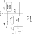
- Fig. 2 shows the UL O-RAN receiver structure for the conventional multiuser, multiple input, multiple output (MU-MIMO) processing.
- a fast Fourier transform FFT
- FFT fast Fourier transform
- the RU combiner module 102 of FIG. 2 is generated at O-DU MU-MIMO combiner generator module 1031, and IQ weight matrix W 1051 is sent back to O-RU. Since the O-RU is not able to estimate the channel matrix from SRS and calculate the MU-MIMO combiner matrix, the RU combiner module 102 needs to be calculated at the O-DU and sent back to the O-RU. Note that the O-RU does not have the ability to compute complex algorithms such as channel estimation and zero-forcing (ZF) or Minimum mean square error - interference rejection combining (MMSE-IRC) design.
- ZF zero-forcing
- MMSE-IRC Minimum mean square error - interference rejection combining
- Pre-processed SRS (signal across all antennas) 1041 is sent to the O-DU to calculate (generate) MU-MIMO combiner at the O-DU MU-MIMO combiner generator module 1031. Since the period of SRS is long (e.g., 10ms), the channel information on the combiner would be outdated (also referenced as channel aging), and degrades performance.
- the MU-MIMO combiner would be either ZF or MMSE-IRC, while the RU combiner module 102 could be any type of multi-user combiner.
- Document US 2019/174527 relates to a wireless communication system, and more particularly, to an uplink multi-input multi-output (MIMO) transmission method and an apparatus for supporting the same.
- MIMO multi-input multi-output
- the present invention relates to a method of generating and applying combining weights to Physical Uplink Shared Channel, PUSCH, symbols for Open Radio Access Network, O-RAN, fronthaul interface between O-RAN radio unit, O-RU, and O-RAN distributed unit, O-DU, as defined in claim 1.
- PUSCH Physical Uplink Shared Channel
- O-RAN Open Radio Access Network
- the present invention further relates to a method of generating and applying combining weights to Physical Uplink Shared Channel, PUSCH, symbols for Open Radio Access Network, O-RAN, fronthaul interface between O-RAN radio unit, O-RU, and O-RAN distributed unit, O-DU, as defined in claim 2.
- PUSCH Physical Uplink Shared Channel
- O-RAN Open Radio Access Network
- First example method for calculating and applying the combining weights according to the present disclosure includes the following:
- an example embodiment provides defining a new combining mode (DMRS-based split combining mode) via M-plane.
- Second example method for calculating and applying the combining weights according to the present disclosure includes the following:
- an example embodiment provides defining a new combining mode (DMRS/SRS-based split combining mode) via M-plane.
- Third example method for calculating and applying the combining weights according to the present disclosure includes the following:
- an example embodiment provides defining a new mode for UL combining, DMRS-based Single Combiner.
- another example embodiment provides defining a new section extension (only applicable for CAT-B O-RUs) associated with the C-plane message to request the O-RU to send the associated U-plane message IQ data (e.g., DMRS) across all antennas (i.e., send IQ right away after reception prior to applying the combining matrix).
- the example methods and embodiments of the present disclosure are applicable to, e.g., O-RAN compliant distributed units (O-DUs) and O-RAN compliant radio units (O-RUs) that are capable of beamforming/MIMO.
- the example methods and embodiments of the present disclosure are applicable to, e.g., O-RAN compliant combined central unit (O-CU) and O-DU communicating via the O-RAN fronthaul interface to O-RUs that are capable of beamforming/MIMO.
- the example methods and embodiments of the present disclosure are applicable to, e.g., O-RAN compliant systems in which both O-DUs and O-RUs can act as evolved NodeB (eNB) and/or next generation NodeB (gNB) that provides wireless connectivity to UEs in licensed (4G and 5G bands), unlicensed (e.g., 5 GHz Unlicensed National Information Infrastructure (UNII) band), and shared spectrum (e.g., citizens Broadband Radio Services (CBRS) band).
- eNB evolved NodeB
- gNB next generation NodeB
- gNB next generation NodeB
- the present disclosure also supports any existing/future wireless system that supports beamforming/MIMO and is O-RAN compliant.
- BRIEF evolved Node
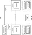
- FIG. 1B is a block diagram of an example embodiment of system 100 for enabling efficient MIMO processing for an O-RAN in a cloud RAN.
- System 100 includes an O-RU 105 and an O-DU 115 that are communicatively coupled via a fronthaul (FH) interface 110, also referred to herein as FH 110.
- FH 110 fronthaul
- a variety of data is communicated via FH 110, including DL and UL U-plane data packets, DL C-plane messages that include data sections and section extension data.
- O-DU 115 instructs O-RU 105 using M-plane and/or C-plane messages regarding i) how to process received messages from O-DU 115 (so that O-RU 105 can send data, reference signals and control information to UE), and ii) how to send messages (received messages from UE) to O-DU 115.
- O-RU 105 and O-DU 115 cooperate with one another to perform a method that enables efficient MIMO processing in the context of FH 110.
- O-RU 105 includes electronic circuitry, namely circuitry 106, that performs operations on behalf of O-RU 105 to execute methods described herein. Circuity 106 may be implemented with any or all of (a) discrete electronic components, (b) firmware, and (c) a programmable circuit 106A.
- O-RU 105 represents mainly an O-RAN-compliant O-RU which executes the lower physical layer blocks such as FFT/IFFT, CP removal/addition, beamforming, analog to digital converter, digital to analog convertor, and RF functions.
- Programmable circuit 106A which is an optional implementation of circuitry 106, includes a processor 107 and a memory 108.
- Processor 107 is an electronic device configured of logic circuitry that responds to and executes instructions.
- Memory 108 is a tangible, non-transitory, computer-readable storage device encoded with a computer program.
- memory 108 stores data and instructions, i.e., program code, that are readable and executable by processor 107 for controlling operations of processor 107.
- Memory 108 may be implemented in a random access memory (RAM), a hard drive, a read only memory (ROM), or a combination thereof.
- One of the components of memory 108 is a program module, namely module 109.
- Module 109 contains instructions for controlling processor 107 to execute operations described herein on behalf of O-RU 105.
- O-DU 115 includes electronic circuitry, namely circuitry 116, that performs operations on behalf of O-DU 115 to execute methods described herein. Circuity 116 may be implemented with any or all of (a) discrete electronic components, (b) firmware, and (c) a programmable circuit 116A.
- O-DU 115 represents an O-RAN compliant O-DU which executes functions such as higher physical layer (based on O-RAN split or similar lower layer splits), MAC, scheduler, and RLC.
- O-DU 115 can be implemented on proprietary hardware or COTS (commercial over the shelf servers) and it can be on the cloud.
- Programmable circuit 116A which is an optional implementation of circuitry 116, includes a processor 117 and a memory 118.
- Processor 117 is an electronic device configured of logic circuitry that responds to and executes instructions.
- Memory 118 is a tangible, non-transitory, computer-readable storage device encoded with a computer program. In this regard, memory 118 stores data and instructions, i.e., program code, that are readable and executable by processor 117 for controlling operations of processor 117.
- Memory 118 may be implemented in a random access memory (RAM), a hard drive, a read only memory (ROM), or a combination thereof.
- One of the components of memory 118 is a program module, namely module 119.
- Module 119 contains instructions for controlling processor 117 to execute operations described herein on behalf of O-DU 115.
- module is used herein to denote a functional operation that may be embodied either as a stand-alone component or as an integrated configuration of a plurality of subordinate components.
- each of module 109 and module 119 may be implemented as a single module or as a plurality of modules that operate in cooperation with one another.
- While modules 109 and 119 are indicated as being already loaded into memories 108 and 118, respectively, either or both of modules 109 and 119 may be configured on a storage device 130 for subsequent loading into their respective memories 108 and 118.
- Storage device 130 is a tangible, non-transitory, computer-readable storage device that stores either or both of modules 109 and 119 thereon.
- Examples of storage device 130 include (a) a compact disk, (b) a magnetic tape, (c) a read only memory, (d) an optical storage medium, (e) a hard drive, (f) a memory unit consisting of multiple parallel hard drives, (g) a universal serial bus (USB) flash drive, (h) a random access memory, and (i) an electronic storage device coupled to O-RU 105 and/or O-DU 115 via a data communications network.
- a compact disk (b) a magnetic tape, (c) a read only memory, (d) an optical storage medium, (e) a hard drive, (f) a memory unit consisting of multiple parallel hard drives, (g) a universal serial bus (USB) flash drive, (h) a random access memory, and (i) an electronic storage device coupled to O-RU 105 and/or O-DU 115 via a data communications network.
- USB universal serial bus
- System 100 also includes an O-RU controller 125, M-plane interface 126, and an O1 interface 129.
- M-plane interface 126 is a communicative link between O-RU controller 125 and O-RU 105.
- O1 interface 129 is a communicative link between O-RU controller 125 and O-DU 115.
- FH 110 is a connection link between O-DU 115 and O-RU 105 that carries control user synchronization (CUS)-plane packets as well as M-plane packets.
- CCS control user synchronization
- O-RU controller 125 is a controller that controls operations of O-RU 105 by exchanging M-plane messages with O-RU 105.
- O-RU 105 reports its capabilities to O-RU controller 125. Subsequently, O-RU controller 125 configures O-RU 105 to operate via M-plane.
- the exchange of M-plane messages between O-RU controller 125 and O-RU 105 can be accomplished by way of two possible paths, namely (1) via M-plane interface 126, or (2) via O1 interface 129, O-DU 115, and FH 110.
- O-RU 105 can report its capabilities to O-RU controller 125, and O-RU controller 125 can send management configuration data to O-RU 105 either (a) directly, via M-plane interface 126, in a hybrid M-plane architecture, or (b) indirectly, via O1 interface 129, O-DU 115 and FH 110, in a hierarchical architecture or hybrid architecture.
- O-RU controller 125 includes electronic circuitry, namely circuitry 124, that performs operations on behalf of O-RU controller 125 to execute methods described herein.
- Circuity 124 may be implemented with any or all of (a) discrete electronic components, (b) firmware, and (c) a programmable circuit.
- Circuitry 124 may be implemented similarly to programmable circuit 116A, i.e., with a processor and a memory that contains instructions that are readable by the processor to control the processor to execute operations on behalf of O-RU controller 125.
- O-RU controller 125 is shown as being a stand-alone device, as an alternative to being a stand-alone device, O-RU controller 125 can reside in either of O-DU 115 a service management and orchestration system (SMO) (not shown), or a network management system (NMS) (not shown).
- SMO service management and orchestration system
- NMS network management system
- the SMO is responsible for RAN domain management.
- the key capabilities of the SMO are: (a) FCAPS interface to O-RAN Network Functions; (b) Non-RT RIC for RAN optimization; and (c) O-Cloud Management, Orchestration and Workflow Management.
- the SMO performs these services through four key interfaces to the O-RAN Elements: (i) A1 Interface between the Non-RT RIC in the SMO and the Near-RT RIC for RAN Optimization; (ii) O1 Interface between the SMO and the O-RAN Network Functions for FCAPS support; (iii) In the hybrid model, Open Fronthaul M-plane interface between SMO and O-RU for FCAPS support; and (iv) O2 Interface between the SMO and the O-Cloud to provide platform resources and workload management.
- the NMS performs FCAP functions and interface for managing network elements.
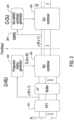
- FIG. 3 illustrates a UL O-RAN receiver structure according to first example embodiment of the present disclosure.
- a fast Fourier transform FFT
- the output is buffered (e.g., at buffer 207) until RU combiner module 203 is generated.
- the output is passed through the RU combiner module 203.
- the number of output streams of the RU combiner module 203 is reduced to the maximum available number of streams (R), and the reduced streams are sent to the O-DU.
- O-DU input IQ data applies DU-combiner 205, and the number of streams is reduced to U.
- the projection matrix generator 202 can utilize a codebook that is N-by-N orthogonal matrix, which is generated by either discrete Fourier transform (DFT) matrix or type I codebook.
- the RU combining matrix is generated in the RU combiner 203 using the projection matrix generated from the projection matrix generator 202.
- the RU combining matrix is applied to the buffered data at the RU combiner 203. Specifically, this can be described in the following manner:
- the codebook by type I codebook can be generated in the following manner:
- the RU combining matrix is generated in the RU combiner 203 using the projection matrix generated from the projection matrix generator 202.
- the RU combining matrix is applied to the buffered data at the RU combiner 203. Specifically, this can be described in the following manner:
- the MU-MIMO combiner at the O-DU MU-MIMO combiner generator module 204 is calculated (generated) based on compressed DMRS 206 (e.g., DMRS across all antennas is compressed by RU combiner).
- DMRS is one example of IQ data, but IQ data can also include PUSCH or SRS symbols.
- the MU-MIMO combiner can be either ZF or MMSE-IRC, while the O-DU combiner 205 can be any type of multi-user combiner. Since the MU-MIMO combiner is calculated (generated) based on DMRS 206, channel aging problem would not happen (DMRS is transmitted every slot).
- the performance can be degraded by loss from the compression of DMRS 206, which is done by the RU combiner.
- the generated MU-MIMO combiner (matrix) is sent to the DU combiner 205 and applied on the DU combiner 205.
- the impact on the O-RAN operation include the following:
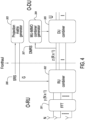
- FIG. 4 illustrates a UL O-RAN receiver structure according to second example embodiment of the present disclosure.
- a fast Fourier transform FFT
- FFT fast Fourier transform
- the number of output streams of the RU combiner module 302 is reduced to the maximum available number of streams (R), and the reduced streams are sent to the O-DU.
- O-DU input IQ data applies DU-combiner 305, and the number of streams is reduced to U.
- the projection matrix generator 303 can utilize a codebook that is N-by-N orthogonal matrix, which is generated by either discrete Fourier transform (DFT) matrix or type I codebook.
- DFT discrete Fourier transform
- SRS 306 across all antennas is applied to generate (calculate) the projection matrix at the projection matrix generator 303.
- SRS 306 is sent from the O-RU to the O-DU without compression (e.g., the RU combiner module 302 is not applied on SRS 306).
- the O-RU Since the RU combiner module 302 is calculated at the O-DU and sent to the O-RU in this example embodiment, the O-RU does not need to calculate any matrix to obtain the RU combiner module 302. In this example embodiment, note that the O-RU does not have the ability to calculate complex algorithms. It should be noted that the performance would be degraded (e.g., in comparison to the first example embodiment) by using SRS to calculate the RU combiner, as the RU combiner obtained by using SRS would be outdated.
- the MU-MIMO combiner at the O-DU MU-MIMO combiner generator module 304 is calculated (generated) based on compressed DMRS 307 (e.g., IQ data across all antennas is compressed by RU combiner).
- the MU-MIMO combiner can be either ZF or MMSE-IRC, while the O-DU combiner 305 can be any type of multi-user combiner. Since the MU-MIMO combiner is calculated (generated) based on DMRS 307 in this example embodiment, channel aging problem would not happen (DMRS is transmitted every slot). On the other hand, the performance can be degraded by loss from the compression of DMRS 307, which is done by the RU combiner 302.
- the MU-MIMO combiner (matrix) generated by the MU-MIMO combiner generator 304 is sent to the DU combiner 305 and applied on the DU combiner 305.
- the impact on the O-RAN operation include the following:
- FIG. 5 illustrates a third example embodiment of the present disclosure.
- the O-RU sends the pre-processed DMRS signal (across all antennas) for a given TTI to DU, as represented by the process arrow 501.
- the O-RU buffers the PUSCH data samples locally, e.g., at the PUSCH data symbols buffer 502.
- the O-DU calculates, at block 503, the combiner matrix based on the DMRS signal and sends the combiner matrix to the O- RU, e.g., to the combining matrix buffer 504.
- the O-RU applies, at block 505, the combiner matrix to the buffered IQ data and sends (as represented by the process arrow 506) the output to the O-DU.
- the impact on the O-RAN operation include the following:
- FIG. 6 illustrates an example O-RAN system architecture, in which the upper physical layer (U-PHY) blocks such as the scrambling, modulation, layer mapping, RE mapping, and I/Q compression (as well as optional precoding, which may be bypassed in bypass mode) can be implemented in the O-DU 601.
- the I/Q decompression, precoding, digital beamforming, IFFT, CP addition, digital-to-analog conversion, and optionally analog beamforming can be implemented in the O-RU 602.
- O-RAN fronthaul (FH) 603 is shown between O-DU and O-RU.
Landscapes
- Engineering & Computer Science (AREA)
- Signal Processing (AREA)
- Computer Networks & Wireless Communication (AREA)
- Mobile Radio Communication Systems (AREA)
- Radio Transmission System (AREA)
Description
- The present disclosure relates to systems and methods for Radio Access Networks (RANs), and relates more particularly to Open RANs (O-RANs) for 4th-Generation (4G) and 5th-Generation (5G) based mobile networks.
- Conventional RANs were built employing an integrated unit where the entire RAN was processed. Conventional RANs implement the protocol stack (e.g., Physical Layer (PHY), Media Access Control (MAC), Radio Link Control (RLC), Packet Data Convergence Control (PDCP) layers) at the base station (also referred to as the evolved node B (eNodeB or eNB) for 4G LTE or next generation node B (gNodeB or gNB) for 5G NR). In addition, conventional RANs use application specific hardware for processing, which make the conventional RANs difficult to upgrade and evolve. As future networks evolve to have massive densification of networks to support increased capacity requirements, there is a growing need to reduce the capital and operating costs of RAN deployment and make the solution scalable and easy to upgrade.
- Cloud-based Radio Access Networks (CRANs) are networks where a significant portion of the RAN layer processing is performed at a baseband unit (BBU), located in the cloud on commercial off the shelf servers, while the radio frequency (RF) and real-time critical functions can be processed in the remote radio unit (RRU), also referred to as the radio unit (RU). The BBU can be split into two parts: centralized unit (CU) and distributed unit (DU). CUs are usually located in the cloud on commercial off the shelf servers, while DUs can be distributed. The BBU may also be virtualized, in which case it is also known as vBBU. Radio Frequency (RF) interface and real-time critical functions can be processed in the remote radio unit (RRU).
- For the RRU and DU to communicate, an interface called the fronthaul is provided. 3rd Generation Partnership Project (3GPP) has defined 8 options for the split between the BBU and the RRU among different layers of the protocol stack. There are multiple factors affecting the selection of the fronthaul split option such as bandwidth, latency, implementation cost, virtualization benefits, complexity of the fronthaul interface, expansion flexibility, computing power, and memory requirement. One of the splits recently standardized by O-RAN Alliance is split option 7-2x (Intra-Physical (PHY) layer split). In the uplink (UL), Fast Fourier Transform (FFT), Cyclic Prefix (CP) removal, and possibly pre-filtering functions reside in the RU, while the rest of PHY functions reside in the DU. In the downlink (DL), inverse Fast Fourier Transform (iFFT), CP addition, and beamforming functions reside in the RU, the rest of PHY functions reside in the DU. This split has multiple advantages such as simplicity, transport bandwidth scalability, beamforming support, interoperability, support for advanced receivers and inter-cell coordination, lower O-RU complexity, future proof-ness, interface and functions symmetry.
- An Open Radio Access Network (O-RAN) is a totally disaggregated approach to deploying mobile fronthaul and midhaul networks, built entirely on cloud native principles. The O-RAN Alliance issues specifications and releases open source software under the auspices of the Linux Foundation.
- An O-RAN Distributed Unit (O-DU) is a part of an O-RAN system typically implemented in software. More specifically, an O-DU is a logical node hosting RLC/MAC/High-PHY layers based on a lower layer functional split.
- An O-RAN Radio Unit (O-RU) is a logical node hosting Low-PHY layer and RF processing based on a lower layer functional split. This is similar to 3GPP's "TRP" or "RRH" but more specific in including the Low-PHY layer (FFT/iFFT, PRACH extraction).
- O-RAN has selected a single split point, known as "7-2x" but allows a variation, with the precoding function to be located either "above" the interface in the O-DU or "below" the interface in the O-RU. For the most part the interface is not affected by this decision, but there are some impacts namely to provide the necessary information to the O-RU to execute the precoding operation. O-RUs within which the precoding is not done (therefore of lower complexity) are called "Category A" O-RUs while O-RUs within which the precoding is done are called "Category B" O-RUs.
- User equipment (UE) is a device allowing a user access to network services, such as a mobile phone.
- An uplink (UL) refers to the traffic flow from the UE to the network and through different network components in the uplink direction. From the UE to the O-RU, the interface is air, while the UL traffic from the O-RU to the O-DU can have different forms (e.g., Ethernet connection).
- A downlink (DL) refers to the traffic flow through network components in the downlink direction and from the network to the UE. From the O-DU to the O-RU, the fronthaul interface can have different forms (e.g., Ethernet), while from the O-RU to the UE is air interface.
- A sounding reference signal (SRS) is a reference signal sent in the UL direction from the UE to the network for the purpose of channel sounding.
- 4G and/or 5G massive multiple input, multiple output (mMIMO) is an example technology that uses the O-RAN 7.2x specifications. In mMIMO systems, the gNB serves multiple users at the same time using the same time/frequency resources. In UL, UEs send sounding reference signals (SRS) over a relatively long period of time, which are sent to the O-DU from the O-RU via the fronthaul interface. Using the SRS, the O-DU then calculates the channel estimates, user pairing and combining matrix for the scheduled users. The O-DU sends the combining matrix weights to the O-RU, which in return applies these weights to the Physical Uplink Shared Channel (PUSCH) symbols and sends the frequency domain In-phase and Quadrature (IQ) samples to the O-DU.
- Although split option 7-2x enables multiple advanced features such as beamforming, UL Coordinated Multi-Point transmission/reception (CoMP), etc., the system performance may degrade in certain scenarios such as UL mMIMO for high-speed UEs. The reason for such degradation in high-speed UEs' scenarios is channel aging, i.e., due to the SRS signals being sent over a relatively long-period of time (e.g., tens of milliseconds). By the time the O-RU applies the combining weights to the PUSCH symbols, these combining weights become inaccurate since the SRS signals are outdated (i.e., SRS to UL-data transmission time interval (TTI) delay is long). In other words, the channel gains between the UEs and the gNB are no longer reflected accurately by the SRS signals (since UEs are moving fast in such scenario), which cause interference and throughput degradation during the combining process in the UL chain.
- In a conventional mMIMO UL processing, the following steps are performed:
- 1) UEs send the SRS signals to the O-RU over the air (OTA).
- 2) The O-RU applies analog-to-digital conversion (ADC), Fast Fourier Transform (FFT) and cyclic prefix (CP) removal and transfers the frequency-domain (FD) IQ samples of the sounding reference signals (SRS) over all the antennas to the O-DU using O-RAN U-plane message(s) for channel estimation at the O-DU.
- 3) SRS-based channel estimates are used to compute the combining weights at the O-DU.
- 4) The O-DU transfers the combining weights to O-RU using O-RAN C-plane
message Section type 1, along withsection extension 1 orsection extension 11. - 5) The O-RU applies the combining weights to the received signal (i.e., PUCCH/PUSCH) and transfers data layers to the O-DU for further processing.
- The existing O-RAN specifications explain the exact method of sending the C-plane messages in the downlink (DL) direction and sending/receiving the U-plane messages between the O-DU and the O-RU. This method as well as a background on the different planes in the O-RAN specifications are explained in this section.
- There are four planes specified in the O-RAN specs namely user-plane (U-plane), control plane (C-plane), synchronization plane (S-plane), and management plane (M-plane). The U-plane refers to IQ sample data transferred between O-DU and O-RU. The C-plane refers specifically to real-time control between O-DU and O-RU and should not be confused with the UE's control plane. The S-plane refers to traffic between the O-RU or O-DU to a synchronization controller, which is generally an IEEE 1588 Grand Master. However, Grand Master functionality may be embedded in the O-DU. The M-plane refers to non-real-time management operations to and from the O-RU. These non-real time management operations are executed by the O-RU and an O-RU controller in both directions. The O-RU controller can reside in the O-DU or a service management and orchestration system (SMO), or can be a separate entity.
- An M-plane interface is a link between the O-RU controller and the O-RU that carries non-real-time management information back and forth.
- The main purpose of the C-plane messages is to transmit data-associated control information required for processing of user data (e.g., scheduling and beamforming commands). These messages are sent separately for DL-related commands and UL-related commands.
- A common frame format is used for C-Plane messages, consisting of a transport layer and an application layer. The application layer is within the transport layer payload and consists of a common header for time reference, followed by information and parameters dependent and specific to the Section Type in use. Multiple sets of section data of the same Section Type value can be lined up one after another within the payload. To minimize packet rate over the interface, transmitter should fill messages with as many subsequent sections (with or without sequential section IDs) as possible.
- To simplify the description of the invention, the following sections of the present disclosure focus on a specific combining method (via sending real-time weights) which can be applied to specific section types (
Section types 1 and 3) using section extension type 1 (as an example). However, this example should not be interpreted as limiting the scope of the present disclosure since the example method or a variant of the method may be applied to other existing beamforming (also referred to as combining) methods or future beamforming/combining methods that will be standardized by O-RAN alliance. -
Section Type 1 is used for most Downlink and Uplink radio channels. The fields ofSection type 1 can be explained as follows: - Transport Layer
- Application Layer
- o Common Header Fields
- ▪ dataDirection (data direction (gNB Tx/Rx)) field: 1 bit
- ▪ payloadVersion (payload version) field: 3 bits
- value = "1" shall be set (1st protocol version for payload and time reference format)
- ▪ filter Index (filter index) field: 4 bits
- ▪ frameld (frame identifier) field: 8 bits
- ▪ subframeld (subframe identifier) field: 4 bits
- ▪ slotID (slot identifier) field: 6 bits
- ▪ startSymbolid (start symbol id) field: 6 bits
- ▪ numberOfsections (number of sections) field: 8 bits
- ▪ sectionType (section type) field: 8 bits
- value = "1" shall be set
- ▪ udCompHdr (user data compression header) field: 8
bits 11 - ▪ reserved (reserved for future use) field: 8 bits
- ∘ Section Fields
- ▪ sectionld (section identifier) field: 12 bits
- ▪ rb (resource block identifier) field: 1 bit
- ▪ symlnc (symbol number increment command) field: 1 bit
- ▪ startPrbc (starting PRB of data section description) field: 10 bits
- ▪ numPrbc (number of contiguous PRBs per data section description) field: 8 bits
- ▪ reMask (resource element mask) field: 12 bits
- ▪ numSymbol (number of symbols) field: 4 bits
- ▪ ef (extension flag) field: 1 bit
- ▪ beamld (beam identifier) field: 15 bits
- o Common Header Fields
- In the method of beamforming/combining via sending real-time weights, the O-DU generates complex combining weights and send these weights to the O-RU via the fronthaul interface.
-
FIG. 1A illustrates scheduling and beamforming commands frame format for section type "1". WithinSection Type 1 message, there could be multiple sections with different section IDs, as shown inFIG. 1A . As shown inFIG. 1A , below the transport header section, a radio application header section (labeled "RAH") is provided, followed by repeated sections each starting with sectionlD. The conventional approach for sending the combining weights to the O-RU based on the SRS signal is not efficient for specific scenarios such as high-speed UEs because the SRS signal is sent over a long period of time, after which time the SRS signal may not accurately reflect the actual channel gains between the gNB and the UEs. -
Fig. 2 shows the UL O-RAN receiver structure for the conventional multiuser, multiple input, multiple output (MU-MIMO) processing. Atblock 1011, a fast Fourier transform (FFT) is performed on the received signals, and the output is passed through theRU combiner module 102. The number of output streams ofRU combiner module 102 is reduced to the number of UE (U), and the reduced streams are sent to the O-DU. - The
RU combiner module 102 ofFIG. 2 is generated at O-DU MU-MIMOcombiner generator module 1031, and IQweight matrix W 1051 is sent back to O-RU. Since the O-RU is not able to estimate the channel matrix from SRS and calculate the MU-MIMO combiner matrix, theRU combiner module 102 needs to be calculated at the O-DU and sent back to the O-RU. Note that the O-RU does not have the ability to compute complex algorithms such as channel estimation and zero-forcing (ZF) or Minimum mean square error - interference rejection combining (MMSE-IRC) design. - Pre-processed SRS (signal across all antennas) 1041 is sent to the O-DU to calculate (generate) MU-MIMO combiner at the O-DU MU-MIMO
combiner generator module 1031. Since the period of SRS is long (e.g., 10ms), the channel information on the combiner would be outdated (also referenced as channel aging), and degrades performance. The MU-MIMO combiner would be either ZF or MMSE-IRC, while theRU combiner module 102 could be any type of multi-user combiner. - Accordingly, there is a need for improved methods for calculating (generating) and applying the combining weights to the PUSCH symbols in the context of the O-RAN fronthaul interface.
- Document
US 2019/174527 relates to a wireless communication system, and more particularly, to an uplink multi-input multi-output (MIMO) transmission method and an apparatus for supporting the same. - Document by O-RAN FRONTHAUL WORKING GROUP 4: "Control, User and Synchronization Plane Specification", 2 August 2019, pages 1-218, specifies the control plane, user plane and synchronization plane protocols used over the fronthaul interface linking the O-DU with the O-RU with a Lower Layer Functional Split-7-2x based architecture.
- Document by ZTE, "Further discussion on LLS", 3GPP DRAFT, R3-174415, vol. RAN WG3, no. Reno, Nevada, 17 November 2017, clarifies LLS evaluation criterion and L1 processing diagram pertaining to option 7-3.
- Document O-RAN FRONTHAUL WORKING GROUP: "Control, User and Synchronization Plane Specification", vol. O-RAN.WG4.CUS.0-v03.00, 1 April 2020, specifies the control plane, user plane and synchronization plane protocols used over the fronthaul interface linking the O-DU with the O-RU with a Lower Layer Functional Split-7-2x based architecture.
- However, the above-mentioned issues are not solved.
- The present invention relates to a method of generating and applying combining weights to Physical Uplink Shared Channel, PUSCH, symbols for Open Radio Access Network, O-RAN, fronthaul interface between O-RAN radio unit, O-RU, and O-RAN distributed unit, O-DU, as defined in
claim 1. - The present invention further relates to a method of generating and applying combining weights to Physical Uplink Shared Channel, PUSCH, symbols for Open Radio Access Network, O-RAN, fronthaul interface between O-RAN radio unit, O-RU, and O-RAN distributed unit, O-DU, as defined in
claim 2. - First example method for calculating and applying the combining weights according to the present disclosure includes the following:
-
- a. The codebook is designed at O-DU and is sent to O-RU.
- b. Alternatively, the codebook can be directly designed by O-RU.
- c. The codebook will be the orthogonal matrix designed by either discrete Fourier transform (DFT) matrix or type I codebook.
-
- a. The codebook is given by O-DU (and the codebook is buffered at O-RU), which is used to design RU combining matrix at the O-RU (RU combiner). The buffered codebook does not need to update periodically.
- b. The projection matrix is selected from the best codebook, and N-by-N codebook is reduced to R-by-N projection matrix.
-
- a. O-RU will send compressed IQ data to O-DU by applying RU combination matrix. In that case, N (the number of base station (BS) antennas) dimension IQ data is reduced to R dimension IQ data.
-
- a. O-DU will calculate the combining matrix by the compressed DMRS. Note that N dimension demodulation reference signal (DMRS) is reduced to R while DMRS is sent from O-RU to O-DU.
- b. The DU combination matrix will be designed by either zero-forcing (ZF) or MMSE-IRC.
- For the first example method, an example embodiment provides defining a new combining mode (DMRS-based split combining mode) via M-plane.
- Second example method for calculating and applying the combining weights according to the present disclosure includes the following:
- 1) Calculating the projection matrix at the O-DU and sending it back to CAT-B O-RU:
- a. O-DU will design projection matrix from SRS across all antennas, which SRS is sent from O-RU. O-DU calculates the projection matrix the same way as in the first example method, except SRS is multiplied by the codebook to find the best R rows.
- b. O-DU will send the projection matrix back to O-RU, and O-RU will apply the projection matrix to the RU combiner. The DU combiner design is done as in the first example method.
- For the second example method, an example embodiment provides defining a new combining mode (DMRS/SRS-based split combining mode) via M-plane.
- Third example method for calculating and applying the combining weights according to the present disclosure includes the following:
- 1) CAT-B O-RU sends pre-processed DMRS signal (across all antennas) for a given TTI to O-DU.
- 2) RU buffers the PUSCH samples locally.
- 3) DU calculates the combiner matrix based on DMRS signal and sends to RU.
- 4) RU applies the combiner matrix to the buffered IQ data and sends to DU.
- For the third example method, an example embodiment provides defining a new mode for UL combining, DMRS-based Single Combiner. In addition, another example embodiment provides defining a new section extension (only applicable for CAT-B O-RUs) associated with the C-plane message to request the O-RU to send the associated U-plane message IQ data (e.g., DMRS) across all antennas (i.e., send IQ right away after reception prior to applying the combining matrix).
The example methods and embodiments of the present disclosure are applicable to, e.g., O-RAN compliant distributed units (O-DUs) and O-RAN compliant radio units (O-RUs) that are capable of beamforming/MIMO. The example methods and embodiments of the present disclosure are applicable to, e.g., O-RAN compliant combined central unit (O-CU) and O-DU communicating via the O-RAN fronthaul interface to O-RUs that are capable of beamforming/MIMO. The example methods and embodiments of the present disclosure are applicable to, e.g., O-RAN compliant systems in which both O-DUs and O-RUs can act as evolved NodeB (eNB) and/or next generation NodeB (gNB) that provides wireless connectivity to UEs in licensed (4G and 5G bands), unlicensed (e.g., 5 GHz Unlicensed National Information Infrastructure (UNII) band), and shared spectrum (e.g., Citizens Broadband Radio Services (CBRS) band). The present disclosure also supports any existing/future wireless system that supports beamforming/MIMO and is O-RAN compliant. BRIEF -
-
FIG. 1A illustrates the scheduling and beamforming commands frame format (Section Type "1") according to the O-RAN specifications. -
FIG. 1B is a block diagram of an example embodiment of system for enabling efficient MIMO processing for an O-RAN in a cloud RAN. -
FIG. 2 illustrate the UL O-RAN receiver structure for the conventional MU-MIMO processing. -
FIG. 3 illustrate a UL O-RAN receiver structure according to first example embodiment of the present disclosure. -
FIG. 4 illustrate a UL O-RAN receiver structure according to second example embodiment of the present disclosure. -
FIG. 5 illustrate third example embodiment of the present disclosure. -
FIG. 6 illustrates an example O-RAN system architecture. -
FIG. 1B is a block diagram of an example embodiment ofsystem 100 for enabling efficient MIMO processing for an O-RAN in a cloud RAN.System 100 includes an O-RU 105 and an O-DU 115 that are communicatively coupled via a fronthaul (FH)interface 110, also referred to herein asFH 110. A variety of data is communicated viaFH 110, including DL and UL U-plane data packets, DL C-plane messages that include data sections and section extension data. O-DU 115 instructs O-RU 105 using M-plane and/or C-plane messages regarding i) how to process received messages from O-DU 115 (so that O-RU 105 can send data, reference signals and control information to UE), and ii) how to send messages (received messages from UE) to O-DU 115. O-RU 105 and O-DU 115 cooperate with one another to perform a method that enables efficient MIMO processing in the context ofFH 110. - O-
RU 105 includes electronic circuitry, namelycircuitry 106, that performs operations on behalf of O-RU 105 to execute methods described herein.Circuity 106 may be implemented with any or all of (a) discrete electronic components, (b) firmware, and (c) aprogrammable circuit 106A. O-RU 105 represents mainly an O-RAN-compliant O-RU which executes the lower physical layer blocks such as FFT/IFFT, CP removal/addition, beamforming, analog to digital converter, digital to analog convertor, and RF functions. -
Programmable circuit 106A, which is an optional implementation ofcircuitry 106, includes aprocessor 107 and amemory 108.Processor 107 is an electronic device configured of logic circuitry that responds to and executes instructions.Memory 108 is a tangible, non-transitory, computer-readable storage device encoded with a computer program. In this regard,memory 108 stores data and instructions, i.e., program code, that are readable and executable byprocessor 107 for controlling operations ofprocessor 107.Memory 108 may be implemented in a random access memory (RAM), a hard drive, a read only memory (ROM), or a combination thereof. One of the components ofmemory 108 is a program module, namelymodule 109.Module 109 contains instructions for controllingprocessor 107 to execute operations described herein on behalf of O-RU 105. - O-
DU 115 includes electronic circuitry, namelycircuitry 116, that performs operations on behalf of O-DU 115 to execute methods described herein.Circuity 116 may be implemented with any or all of (a) discrete electronic components, (b) firmware, and (c) aprogrammable circuit 116A. O-DU 115 represents an O-RAN compliant O-DU which executes functions such as higher physical layer (based on O-RAN split or similar lower layer splits), MAC, scheduler, and RLC. O-DU 115 can be implemented on proprietary hardware or COTS (commercial over the shelf servers) and it can be on the cloud. -
Programmable circuit 116A, which is an optional implementation ofcircuitry 116, includes aprocessor 117 and amemory 118.Processor 117 is an electronic device configured of logic circuitry that responds to and executes instructions.Memory 118 is a tangible, non-transitory, computer-readable storage device encoded with a computer program. In this regard,memory 118 stores data and instructions, i.e., program code, that are readable and executable byprocessor 117 for controlling operations ofprocessor 117.Memory 118 may be implemented in a random access memory (RAM), a hard drive, a read only memory (ROM), or a combination thereof. One of the components ofmemory 118 is a program module, namelymodule 119.Module 119 contains instructions for controllingprocessor 117 to execute operations described herein on behalf of O-DU 115. - The term "module" is used herein to denote a functional operation that may be embodied either as a stand-alone component or as an integrated configuration of a plurality of subordinate components. Thus, each of
module 109 andmodule 119 may be implemented as a single module or as a plurality of modules that operate in cooperation with one another. - While
modules memories modules storage device 130 for subsequent loading into theirrespective memories Storage device 130 is a tangible, non-transitory, computer-readable storage device that stores either or both ofmodules storage device 130 include (a) a compact disk, (b) a magnetic tape, (c) a read only memory, (d) an optical storage medium, (e) a hard drive, (f) a memory unit consisting of multiple parallel hard drives, (g) a universal serial bus (USB) flash drive, (h) a random access memory, and (i) an electronic storage device coupled to O-RU 105 and/or O-DU 115 via a data communications network. -
System 100 also includes an O-RU controller 125, M-plane interface 126, and anO1 interface 129. M-plane interface 126 is a communicative link between O-RU controller 125 and O-RU 105.O1 interface 129 is a communicative link between O-RU controller 125 and O-DU 115. -
FH 110 is a connection link between O-DU 115 and O-RU 105 that carries control user synchronization (CUS)-plane packets as well as M-plane packets. - O-
RU controller 125 is a controller that controls operations of O-RU 105 by exchanging M-plane messages with O-RU 105. O-RU 105 reports its capabilities to O-RU controller 125. Subsequently, O-RU controller 125 configures O-RU 105 to operate via M-plane. The exchange of M-plane messages between O-RU controller 125 and O-RU 105 can be accomplished by way of two possible paths, namely (1) via M-plane interface 126, or (2) viaO1 interface 129, O-DU 115, andFH 110. Thus, O-RU 105 can report its capabilities to O-RU controller 125, and O-RU controller 125 can send management configuration data to O-RU 105 either (a) directly, via M-plane interface 126, in a hybrid M-plane architecture, or (b) indirectly, viaO1 interface 129, O-DU 115 andFH 110, in a hierarchical architecture or hybrid architecture. - O-
RU controller 125 includes electronic circuitry, namelycircuitry 124, that performs operations on behalf of O-RU controller 125 to execute methods described herein.Circuity 124 may be implemented with any or all of (a) discrete electronic components, (b) firmware, and (c) a programmable circuit.Circuitry 124 may be implemented similarly toprogrammable circuit 116A, i.e., with a processor and a memory that contains instructions that are readable by the processor to control the processor to execute operations on behalf of O-RU controller 125. - Although O-
RU controller 125 is shown as being a stand-alone device, as an alternative to being a stand-alone device, O-RU controller 125 can reside in either of O-DU 115 a service management and orchestration system (SMO) (not shown), or a network management system (NMS) (not shown). - The SMO is responsible for RAN domain management. The key capabilities of the SMO are: (a) FCAPS interface to O-RAN Network Functions; (b) Non-RT RIC for RAN optimization; and (c) O-Cloud Management, Orchestration and Workflow Management. The SMO performs these services through four key interfaces to the O-RAN Elements: (i) A1 Interface between the Non-RT RIC in the SMO and the Near-RT RIC for RAN Optimization; (ii) O1 Interface between the SMO and the O-RAN Network Functions for FCAPS support; (iii) In the hybrid model, Open Fronthaul M-plane interface between SMO and O-RU for FCAPS support; and (iv) O2 Interface between the SMO and the O-Cloud to provide platform resources and workload management. The NMS performs FCAP functions and interface for managing network elements.
-
FIG. 3 illustrates a UL O-RAN receiver structure according to first example embodiment of the present disclosure. Atblock 201, a fast Fourier transform (FFT) is performed on the received signals, and the output is buffered (e.g., at buffer 207) untilRU combiner module 203 is generated. Then, the output is passed through theRU combiner module 203. The number of output streams of theRU combiner module 203 is reduced to the maximum available number of streams (R), and the reduced streams are sent to the O-DU. Then, O-DU input IQ data applies DU-combiner 205, and the number of streams is reduced to U. - The
projection matrix generator 202 can utilize a codebook that is N-by-N orthogonal matrix, which is generated by either discrete Fourier transform (DFT) matrix or type I codebook. The DFT matrix for the codebook is given as:

- If the
projection matrix generator 202 utilizes a codebook generated by a DFT matrix, the RU combining matrix is generated in theRU combiner 203 using the projection matrix generated from theprojection matrix generator 202. The RU combining matrix is applied to the buffered data at theRU combiner 203. Specifically, this can be described in the following manner: - a. multiply the first symbol of received signal of TTI by projection matrix and obtain absolute value as,

- b. find the indices of R the largest elements of k, and define the indices set µ, which is applied to select the best R row of the projection matrix G as,

- c. obtain the
RU combiner 203 as,
- The codebook by type I codebook can be generated in the following manner:
- a. The DFT vector is defined as,


- b. Then, the aggregate matrix of DFT vector is defined as,


- c. Then, the following matrix is defined:

1 O2 -1 matrices set, and N 1, N 2 are the number of vertical antenna elements and horizontal antenna elements of BS antennas, and ⊗ is Kronecker product operation. - d. Then, the projection matrix set is defined as,

1 O2 -1 projection matrices. - If the
projection matrix generator 202 utilizes a codebook generated by a Type I codebook, the RU combining matrix is generated in theRU combiner 203 using the projection matrix generated from theprojection matrix generator 202. The RU combining matrix is applied to the buffered data at theRU combiner 203. Specifically, this can be described in the following manner: - a. Input: i = 0, G i ,··· ,G O
1 O2 -1, y - b. Multiply the first symbol of received signal of TTI by i-th projection matrix and obtain absolute value as,

- c. Find the indices of R largest elements of k i , and define the indices set µi , which is applied to select the best R row of the projection matrix G i as,

- d. Calculate the sum of the absolute value k i of the selected indices as,

- e. Set i = i + 1, and repeat from step b to d until i = O 1 O 2 -1
- f. Find the best projection matrix by

- g. obtain the
RU combiner 203 as
- The MU-MIMO combiner at the O-DU MU-MIMO
combiner generator module 204 is calculated (generated) based on compressed DMRS 206 (e.g., DMRS across all antennas is compressed by RU combiner). In this disclosure, DMRS is one example of IQ data, but IQ data can also include PUSCH or SRS symbols. The MU-MIMO combiner can be either ZF or MMSE-IRC, while the O-DU combiner 205 can be any type of multi-user combiner. Since the MU-MIMO combiner is calculated (generated) based onDMRS 206, channel aging problem would not happen (DMRS is transmitted every slot). On the other hand, the performance can be degraded by loss from the compression ofDMRS 206, which is done by the RU combiner. The generated MU-MIMO combiner (matrix) is sent to theDU combiner 205 and applied on theDU combiner 205. - In connection with the first example embodiment of the present disclosure illustrated in
FIG. 3 , the impact on the O-RAN operation (i.e., novel modifications provided herein) include the following: - ∘ Define a new combining mode via M-plane:
- ▪ Default mode can be: existing SRS-based method.
- ▪ New mode provided: DMRS-based split combining mode.
- ▪ RU should report whether it can support this new mode (DMRS-based split combining mode). One example implementation is adding a new feature in YANG module: o-ran-module-cap.yang Module to allow the RU to report if it can support the new combining mode).
- ▪ If yes, DU can configure the O-RU to use this method/mode. One example implementation is modifying YANG: o-ran-uplane-conf.yang Module to reflect this new configuration.
- o DU uses default value BeamID = 0 (i.e., no combining) and send C-plane messages to RU.
- o In another example implementation, the codebook is designed at O-DU and is sent to O-RU via M-plane.
- o RU sends R streams to DU instead of U (data layers for UE).
- o Define a bit mask in the eAxC ID to include z (R x 1) for CAT-B (i.e., streams instead of layers for CAT-B).
-
FIG. 4 illustrates a UL O-RAN receiver structure according to second example embodiment of the present disclosure. Atblock 301, a fast Fourier transform (FFT) is performed on the received signals, and the output is passed through theRU combiner module 302. The number of output streams of theRU combiner module 302 is reduced to the maximum available number of streams (R), and the reduced streams are sent to the O-DU. Then, O-DU input IQ data applies DU-combiner 305, and the number of streams is reduced to U. - The
projection matrix generator 303 can utilize a codebook that is N-by-N orthogonal matrix, which is generated by either discrete Fourier transform (DFT) matrix or type I codebook. Instead of applying the received signal at the O-RU as done in the first example embodiment described above in connection withFIG. 3 ,SRS 306 across all antennas is applied to generate (calculate) the projection matrix at theprojection matrix generator 303. In the example embodiment shown inFIG. 4 ,SRS 306 is sent from the O-RU to the O-DU without compression (e.g., theRU combiner module 302 is not applied on SRS 306). Since theRU combiner module 302 is calculated at the O-DU and sent to the O-RU in this example embodiment, the O-RU does not need to calculate any matrix to obtain theRU combiner module 302. In this example embodiment, note that the O-RU does not have the ability to calculate complex algorithms. It should be noted that the performance would be degraded (e.g., in comparison to the first example embodiment) by using SRS to calculate the RU combiner, as the RU combiner obtained by using SRS would be outdated. - The MU-MIMO combiner at the O-DU MU-MIMO
combiner generator module 304 is calculated (generated) based on compressed DMRS 307 (e.g., IQ data across all antennas is compressed by RU combiner). The MU-MIMO combiner can be either ZF or MMSE-IRC, while the O-DU combiner 305 can be any type of multi-user combiner. Since the MU-MIMO combiner is calculated (generated) based onDMRS 307 in this example embodiment, channel aging problem would not happen (DMRS is transmitted every slot). On the other hand, the performance can be degraded by loss from the compression ofDMRS 307, which is done by theRU combiner 302. The MU-MIMO combiner (matrix) generated by the MU-MIMO combiner generator 304 is sent to theDU combiner 305 and applied on theDU combiner 305. - In connection with the second example embodiment of the present disclosure illustrated in
FIG. 4 , the impact on the O-RAN operation (i.e., novel modifications provided herein) include the following: - ∘ Define a new combining mode via M-plane:
- ▪ Default mode can be: Existing SRS-based method.
- ▪ New mode provided: DMRS/SRS-based split combining mode.
- ▪ RU should report whether it can support this new mode (DMRS/SRS-based split combining mode). One example implementation is adding a new feature in YANG module: o-ran-module-cap.yang Module to allow the RU to report if it can support the new combining mode).
- ▪ If yes, DU can configure the O-RU to use this method/mode. One example implementation is modifying YANG: o-ran-uplane-conf.yang Module to reflect this new configuration.
- o DU sends the RU combining weights (defined for the RU combiner) via C-plane messages to RU.
- o RU sends R streams to DU instead of U (data layers for UE).
- o Define a bit mask in the eAxC ID to include z (R x 1) for CAT-B (i.e., streams instead of layers for CAT-B).
-
FIG. 5 illustrates a third example embodiment of the present disclosure. The O-RU sends the pre-processed DMRS signal (across all antennas) for a given TTI to DU, as represented by theprocess arrow 501. The O-RU buffers the PUSCH data samples locally, e.g., at the PUSCHdata symbols buffer 502. The O-DU calculates, atblock 503, the combiner matrix based on the DMRS signal and sends the combiner matrix to the O- RU, e.g., to the combiningmatrix buffer 504. The O-RU applies, atblock 505, the combiner matrix to the buffered IQ data and sends (as represented by the process arrow 506) the output to the O-DU. - In connection with the third example embodiment of the present disclosure, the impact on the O-RAN operation (i.e., novel modifications provided herein) include the following:
- o For the case of CAT-B O-RU sending pre-processed DMRS signal (across all antennas) for a given TTI to O-DU.:
- ▪ Option 1:
- Define a new section extension (only applicable for CAT-B O-RUs) associated with the C-plane message to request the O-RU to send the associated U-plane message IQ data (e.g., DMRS) across all antennas (i.e., send IQ right away after reception prior to applying the combining matrix).
- ▪ Option 2:
- Similar to SRS, the RU needs to deal with DMRS as non-delay managed traffic and assign specific eAxC IDs to the DMRS signals via M-plane (Those eAxC IDs refer to the rx antennas used to transfer the DMRS). Note that the original eAxC IDs are defined for CAT-B for layers, not for antennas
- Define bitmasks for non-delay managed traffic such as SRS and DMRS. These bitmasks are part of the RU port ID. Example:
- ∘ <e-axcid>
- ∘ <o-du-port-bitmask/>
- ∘ <band-sector-bitmask/>
- ∘ <ccid-bitmask/>
- ∘ <ru-port-bitmask/>
- ∘ <band-bitmask/>
- ∘ <sector-bitmask/>
- ∘ <channel-type-bitmask/>
- ∘ <layer-antenna-port-bitmask/>
- ∘ <eaxc-id/>
- ∘ </e-axcid>
- ▪ Option 1:
- o Similar to the first and second example embodiments, a new mode for UL combining is defined for the third example embodiment so that the RU reports if it supports this new combining mode and the DU can choose to configure it. This new combining mode can be called DMRS-based Single Combiner.
-
FIG. 6 illustrates an example O-RAN system architecture, in which the upper physical layer (U-PHY) blocks such as the scrambling, modulation, layer mapping, RE mapping, and I/Q compression (as well as optional precoding, which may be bypassed in bypass mode) can be implemented in the O-DU 601. The I/Q decompression, precoding, digital beamforming, IFFT, CP addition, digital-to-analog conversion, and optionally analog beamforming can be implemented in the O-RU 602. O-RAN fronthaul (FH) 603 is shown between O-DU and O-RU. -
- 3GPP: Third generation partnership project
- A1: Interface between Non-RT RIC in an SMO and Near-RT RIC for RAN OptimizationCAPEX: Capital Expenditure
- CBRS: Citizens Broadband Radio Services
- CC: Component carrier
- COTS: Commercial off-the-shelf
- CP: cyclic prefix
- C-plane: Control plane
- C-RAN: cloud radio access network
- CU: Central unit
- DCI: downlink control indicator
- DL: downlink
- DMRS: demodulation reference signal
- DU: Distribution unit
- eAxC ID: Extended Antenna-Carrier identifier: a data flow for a single antenna (or spatial stream) for a single carrier in a single sector.
- eNB: Evolved Node B
- FCAPS: Fault, Configuration, Accounting, Performance, Security
- FDD: Frequency-division duplex
- FEC: forward error correction
- FH: Fronthaul
- FFT: Fast Fourier Transform
- iFFT: inverse Fast Fourier Transform
- IQ: In-phase and Quadrature
- HARQ: hybrid automatic repeat request
- LTE: long term evolution
- LTE-A: LTE Advanced
- M-plane: Management plane
- MCS: modulation and coding scheme
- MIMO: multiple input, multiple output
- mMIMO: massive multiple input, multiple output
- MU-MIMO: multiuser, multiple input, multiple output
- MMSE-IRC: Minimum mean square error - interference rejection combining
- MMSE-MRC: Minimum mean square error - maximum-ratio combining
- mm Wave: millimeter wave
- MNO: Mobile network operator
- Near RT RIC: Near-Real-Time RAN Intelligent Controller
- Non-RT RIC: O-RAN Non-Real-Time RAN Intelligent Controller
- NR: New radio
- OAM: Operation and management
- O1: Interface between SMO framework specified in O-RAN Architecture and O-RAN managed elements, for operation and management, by which FCAPS management, PNF software management, and file management are achieved
- O2: Interface between SMO framework as specified in O-RAN architecture and the O-Cloud for supporting O-RAN virtual network functions
- O-Cloud: A cloud computing platform that includes a collection of physical infrastructure nodes that meet O-RAN requirements to host relevant O-RAN functions (such as Near-RT RIC, O-CU-CP, O-CU-UP, and O-DU), supporting software components (such as Operating System, Virtual Machine Monitor, and Container Runtime), and management and orchestration functions
- O-CU: O-RAN Centralized Unit
- O-DU: O-RAN Distributed Unit
- O-RU: O-RAN Radio Unit
- O-RAN: Open RAN (Basic O-RAN specifications are prepared by the O-RAN alliance)
- OPEX: Operating Expense
- PBCH: Physical Broadcast Channel
- PCFICH: Physical Control Format Indicator Channel
- PDCCH: Physical downlink Control Channel
- PDCP: Packet Data Convergence Protocol
- PDSCH: physical downlink shared channel
- PHICH: Physical Hybrid ARQ Indicator Channel
- PHY: physical layer
- LPHY: lower physical layer
- UPHY: upper physical layer
- PNF: Physical Network Function
- PUCCH: Physical Uplink Control Channel
- PUSCH: Physical Uplink Shared Channel
- QAM: quadrature amplitude modulation
- QPSK: Quadrature Phase Shift Keying
- RACH: random access channel
PRACH: physical random access channel - RF: radio frequency interface
- RLC: Radio Link Control
- RRC: Radio Resource Control
- RRH: Remote Radio Head
- RRM: Radio resource management
- RRU: Remote radio unit
- RU: Radio Unit
- RS: reference signal
- RSSI: received signal strength indicator
- S-plane: Synchronization plane
- SCell: Secondary cell
- SIMO: single input, multiple output
- SINR: signal-to-interference-plus-noise ratio
- SRS: Sounding reference signal
- SSS: Secondary Synchronization Signal
- TB: transport block
- TRP: Transmission Reception Point
- TTI: Transmission Time Interval
- TDD: Time division duplex
- U-plane: User plane
- UCI: Uplink Control Information
- UE: user equipment
- UL: uplink
- UL DMRS: uplink demodulation reference signal
- ULSCH: Uplink Shared Channel
- vBBU: Virtualized baseband unit
- VNF: Virtual Network Function
- ZF: Zero-Forcing
Claims (14)
- A method of generating and applying combining weights to Physical Uplink Shared Channel, PUSCH, symbols for Open Radio Access Network, O-RAN, fronthaul interface between O-RAN radio unit, O-RU, and O-RAN distributed unit, O-DU, comprising:calculating, by the O-RU, a projection matrix using a codebook;generating, by the O-RU, an RU combiner matrix, using the codebook;applying, by the O-RU, the RU combiner matrix to In-phase and Quadrature, IQ, data to generate compressed IQ data;compressing, by the O-RU, PUSCH and demodulation reference signal, DMRS, symbols from the RU combiner matrix;sending, by the O-RU, the compressed IQ data associated with the compressed DMRS symbols to the O-DU;calculating, by the O-DU, a DU combiner matrix from the compressed DMRS symbols;applying, by the O-DU, the DU combiner matrix to the compressed PUSCH symbols; andgenerating, by the O-DU, a multiuser multiple input, multiple output, MU-MIMO, combiner matrix.
- A method of generating and applying combining weights to Physical Uplink Shared Channel, PUSCH, symbols for Open Radio Access Network, O-RAN, fronthaul interface between O-RAN radio unit, O-RU, and O-RAN distributed unit, O-DU, comprising:sending, by the O-RU, a sounding reference signal, SRS, for multiple antennas to the O-DU;calculating, by the O-DU, a projection matrix from a codebook;generating, by the O-DU, an RU combiner matrix;sending, by the O-DU, the RU combiner matrix to the O-RU;applying, by the O-RU, the RU combiner matrix to In-phase and Quadrature, IQ, data to generate compressed IQ data;compressing, by the O-RU, PUSCH and demodulation reference signal, DMRS, symbols from the RU combiner matrix;sending, by the O-RU, the compressed IQ data associated with the compressed DMRS symbols to the O-DU;calculating, by the O-DU, a DU combiner matrix from the compressed DMRS symbols;applying, by the O-DU, the DU combiner matrix to the compressed PUSCH symbols; andgenerating, by the O-DU, a multiuser multiple input, multiple output, MU-MIMO, combiner matrix.
- The method according to claim 1, wherein at least one of:a) the projection matrix is obtained by the best codebook search;b) the codebook is one of i) a single discrete Fourier transform, DFT, matrix or ii) a set of matrices from type I codebook; andc) the O-RU generates and buffers the codebook.
- The method according to claim 2, wherein the codebook is one of i) a single discrete Fourier transform, DFT, matrix or ii) a set of matrices from type I codebook.
- The method according to claim 3, wherein:the first symbol of transmission time interval, TTI, is used as an input of a projection matrix generator; andthe projection matrix generator obtains the projection matrix incorporated with the codebook.
- The method according to claim 4, wherein:the first symbol of transmission time interval, TTI, is used as an input of a projection matrix generator; andthe projection matrix generator obtains the projection matrix incorporated with the codebook.
- The method according to claim 1, further comprising:sending, by the O-DU, the codebook to the O-RU via the fronthaul interface; andbuffering, by the O-RU, the codebook.
- The method according to claim 7, wherein the buffered codebook is not updated periodically.
- The method according to claim 2, further comprising:
at least one of i) sending, by the O-DU, the projection matrix calculated by the O-DU to the O-RU, ii) applying, by the O-RU, the projection matrix to an O-RU combiner module, and iii) calculating, by the O-DU, the codebook. - The method according to claim 1, further comprising:
at least one of i) calculating, by the O-DU, the codebook, and ii) sending, by the O-DU, the codebook to O-RU. - The method according to claim 1, further comprising:reporting, by the O-RU via management plane to an O-RU controller, whether the O-RU supports demodulation reference signal (DMRS)-based split combining mode; andif the O-RU supports the DMRS-based split combining mode, configuring the O-RU by the O-RU controller via the management plane to operate in the DMRS-based split combining mode.
- The method according to claim 11, further comprising:
sending, by the O-RU to the O-DU via the fronthaul interface, a number of data streams in the DMRS-based split combining mode larger than the number of data layers for UEs. - The method according to claim 2, further comprising:reporting, by the O-RU via management plane to an O-RU controller, whether the O-RU supports demodulation reference signal, DMRS, and sounding reference signal, SRS,-based split combining mode; andif the O-RU supports the DMRS and SRS-based split combining mode, configuring the O-RU by the O-RU controller via the management plane to operate in the DMRS and SRS-based split combining mode.
- The method according to claim 13, further comprising:
sending, by the O-RU to the O-DU via the fronthaul interface, a number of data streams in the DMRS and SRS-based split combining mode larger than the number of data layers for UEs.
Applications Claiming Priority (2)
| Application Number | Priority Date | Filing Date | Title |
|---|---|---|---|
| US202063053967P | 2020-07-20 | 2020-07-20 | |
| US17/376,505 US12438578B2 (en) | 2020-07-20 | 2021-07-15 | Method for enabling efficient MIMO processing for O-RAN fronthaul interface in cloud RAN systems |
Publications (3)
| Publication Number | Publication Date |
|---|---|
| EP3955470A2 EP3955470A2 (en) | 2022-02-16 |
| EP3955470A3 EP3955470A3 (en) | 2022-05-04 |
| EP3955470B1 true EP3955470B1 (en) | 2024-05-01 |
Family
ID=79292902
Family Applications (1)
| Application Number | Title | Priority Date | Filing Date |
|---|---|---|---|
| EP21186189.3A Active EP3955470B1 (en) | 2020-07-20 | 2021-07-16 | Method for enabling efficient mimo processing for o-ran fronthaul interface in cloud ran systems |
Country Status (2)
| Country | Link |
|---|---|
| US (1) | US12438578B2 (en) |
| EP (1) | EP3955470B1 (en) |
Cited By (1)
| Publication number | Priority date | Publication date | Assignee | Title |
|---|---|---|---|---|
| US20230198815A1 (en) * | 2021-12-17 | 2023-06-22 | Intel Corporation | Methods and devices for joint processing in massive mimo systems |
Families Citing this family (28)
| Publication number | Priority date | Publication date | Assignee | Title |
|---|---|---|---|---|
| US11985011B2 (en) * | 2020-07-07 | 2024-05-14 | Intel Corporation | Distributed minimum mean-square error interference rejection combining (MMSE-IRC) processing for radio access networks |
| US11716765B2 (en) | 2020-11-02 | 2023-08-01 | Qualcomm Incorporated | PRACH processing for O-RU |
| US12021660B2 (en) * | 2021-03-01 | 2024-06-25 | At&T Intellectual Property I, L.P. | Method and system for controlling uplink transmit power |
| US11729654B2 (en) * | 2021-05-05 | 2023-08-15 | Qualcomm Incorporated | Communication techniques between a radio unit and a distributed unit via an application programming interface |
| US12231912B2 (en) * | 2021-06-18 | 2025-02-18 | Qualcomm Incorporated | System and method for reporting orbital angular momentum waveform misalignment |
| US11889508B1 (en) * | 2021-09-24 | 2024-01-30 | Keysight Technologies, Inc. | System and method for managing a cellular network |
| EP4487535A1 (en) * | 2022-02-28 | 2025-01-08 | Qualcomm Incorporated | Enhanced fronthaul interface split using demodulation reference signal channel estimates |
| US12494948B2 (en) | 2022-02-28 | 2025-12-09 | Qualcomm Incorporated | Enhanced fronthaul interface split using demodulation reference signal channel estimates |
| WO2023164791A1 (en) * | 2022-03-01 | 2023-09-07 | Mavenir Networks, Inc. | Method and interface for information interaction in o-ran |
| EP4515723A4 (en) * | 2022-04-26 | 2026-03-18 | Ericsson Telefon Ab L M | METHOD AND ONE OR MORE NETWORK UNITS FOR IMPROVED UPLINK CHANNEL ESTIMATION |
| US12328276B2 (en) * | 2022-07-14 | 2025-06-10 | Qualcomm Incorporated | Efficient channel sounding through analog aggregation |
| EP4581858A4 (en) * | 2022-08-30 | 2025-10-08 | Rakuten Symphony Inc | Method and apparatus for statistical multiplexing for front-haul bandwidth in open direct access networks |
| US11838169B1 (en) * | 2022-09-30 | 2023-12-05 | Dell Products L.P. | Remote logging management in multi-vendor O-RAN networks |
| US20240224202A1 (en) * | 2022-10-12 | 2024-07-04 | Ramana Reddy Machireddy | Clock selection in a fronthaul network |
| EP4623519A4 (en) * | 2022-11-23 | 2025-12-24 | Rakuten Symphony Inc | AMPLIFICATION OF A SOUNDING REFERENCE SIGNAL BEAM FORMER WITH TIME CORRECTION |
| US12445980B2 (en) * | 2023-02-13 | 2025-10-14 | Qualcomm Incorporated | Demodulation reference signal sharing across user equipments (UEs) supporting over the air digital pre-distortion |
| US20240291550A1 (en) * | 2023-02-24 | 2024-08-29 | Samsung Electronics Co., Ltd. | Spatial combining of ul in mimo systems |
| EP4684475A1 (en) * | 2023-03-21 | 2026-01-28 | Telefonaktiebolaget LM Ericsson (publ) | Radio network node, first node, second node, and methods performed thereby, for handling exchange of information between the first node managing a radio equipment and the second node managing a controller of the radio equipment |
| US20240348398A1 (en) * | 2023-04-17 | 2024-10-17 | Mavenir Systems, Inc. | On-Demand NDM DMRS for O-RAN-Based Radio Access Networks |
| EP4699235A1 (en) * | 2023-04-17 | 2026-02-25 | Telefonaktiebolaget LM Ericsson (publ) | Dmrs-based uplink dimension reduction in massive mimo radio unit |
| EP4694096A1 (en) * | 2023-04-19 | 2026-02-11 | Samsung Electronics Co., Ltd. | Device and method for processing uplink reference signal within fronthaul interface |
| US12580617B2 (en) * | 2023-06-16 | 2026-03-17 | Hfcl Limited | Systems and methods for efficient time multiplexed digital beamforming |
| US20250031067A1 (en) * | 2023-07-21 | 2025-01-23 | Mavenir Systems, Inc. | Systems and Methods for Energy and Fronthaul Bandwidth Efficient Uplink Performance Improvements for O-RAN-based Radio Access Networks |
| EP4746554A1 (en) * | 2023-08-18 | 2026-05-20 | Samsung Electronics Co Ltd | DEVICE AND METHOD FOR USING A TIME DUPLEX METHOD IN A FRONTHAUL INTERFACE |
| WO2025100986A1 (en) * | 2023-11-09 | 2025-05-15 | Samsung Electronics Co., Ltd. | Methods and apparatus for front haul overhead reduction in a distributed base station architecture in a wireless communication system |
| US20250233708A1 (en) * | 2024-01-16 | 2025-07-17 | Dell Products L.P. | Radio access network splits for reduced radio unit complexity |
| KR20260008549A (en) * | 2024-07-09 | 2026-01-16 | 삼성전자주식회사 | Method and apparatus for transmitting and receiving data via a fronthaul interface in a wireless communication system |
| WO2026014969A1 (en) * | 2024-07-12 | 2026-01-15 | Samsung Electronics Co., Ltd. | System and method for transmitting a demodulation reference signal (dmrs) sequence to user equipment |
Family Cites Families (5)
| Publication number | Priority date | Publication date | Assignee | Title |
|---|---|---|---|---|
| WO2019108048A1 (en) | 2017-12-01 | 2019-06-06 | 엘지전자 주식회사 | Method for uplink transmission and reception in wireless communication system and device therefor |
| WO2020242352A1 (en) * | 2019-05-24 | 2020-12-03 | Telefonaktiebolaget Lm Ericsson (Publ) | Methods, distributed base station system, remote radio unit and base band unit system for handling uplink signals |
| WO2020256609A1 (en) * | 2019-06-20 | 2020-12-24 | Telefonaktiebolaget Lm Ericsson (Publ) | Methods, distributed base station system, remote radio unit and base band unit system for handling downlink signals |
| CN114208102B (en) * | 2019-07-02 | 2023-03-28 | 康普技术有限责任公司 | Forwarding interface for use with cloud radio access networks |
| KR102906694B1 (en) * | 2019-10-18 | 2025-12-31 | 삼성전자주식회사 | Method and apparatus for delivering a control message in a wireless communication system |
-
2021
- 2021-07-15 US US17/376,505 patent/US12438578B2/en active Active
- 2021-07-16 EP EP21186189.3A patent/EP3955470B1/en active Active
Cited By (2)
| Publication number | Priority date | Publication date | Assignee | Title |
|---|---|---|---|---|
| US20230198815A1 (en) * | 2021-12-17 | 2023-06-22 | Intel Corporation | Methods and devices for joint processing in massive mimo systems |
| US12438752B2 (en) * | 2021-12-17 | 2025-10-07 | Intel Corporation | Methods and devices for joint processing in massive MIMO systems |
Also Published As
| Publication number | Publication date |
|---|---|
| EP3955470A2 (en) | 2022-02-16 |
| US12438578B2 (en) | 2025-10-07 |
| US20220021423A1 (en) | 2022-01-20 |
| EP3955470A3 (en) | 2022-05-04 |
Similar Documents
| Publication | Publication Date | Title |
|---|---|---|
| US12438578B2 (en) | Method for enabling efficient MIMO processing for O-RAN fronthaul interface in cloud RAN systems | |
| US12279156B2 (en) | Traffic timing control for an open radio access network in a cloud radio access network system | |
| CN115053561B (en) | Methods and apparatus to facilitate CSI feedback in multi-TRP communications | |
| CN115633374B (en) | Method for reporting channel state information in wireless communication system and apparatus therefor | |
| JP2020516193A (en) | Method and apparatus for reporting channel state information in a wireless communication system | |
| JP2020503710A (en) | Method and apparatus for performing CSI reporting in a wireless communication system | |
| WO2023070361A1 (en) | Ris configuration computation using reinforcement learning | |
| US12401436B2 (en) | Gradient dropping for federated learning | |
| US20220361222A1 (en) | Srs resource set and beam order association for multi-beam pusch | |
| US9660789B2 (en) | Central network node, first network node, first wireless device, controller network node, and methods therein, of instructing the first network node to transmit to the first wireless device | |
| US20260121705A1 (en) | Tpmi selection based on beamforming category | |
| WO2022204439A1 (en) | Timelines for uplink control information multiplexing over multiple slot transmissions | |
| WO2023019416A1 (en) | Design of precoding codebook for los mimo | |
| US11750255B1 (en) | Beamforming calibration | |
| JP2024517192A (en) | Association of SRS resource sets and beam orders for multi-beam PUSCH | |
| US12184372B2 (en) | Hierarchical channel state information (CSI) feedback with partial reciprocity with user equipment (UE) | |
| US12003300B2 (en) | Hierarchical channel state information (CSI) feedback with partial reciprocity in a network | |
| US12323861B2 (en) | RSU initiated inter-RSU handover | |
| US12401548B2 (en) | Sounding and transmission precoding matrix indication determination using machine learning models | |
| WO2024049633A1 (en) | Activation of network coding based on condition report and position | |
| US20240292383A1 (en) | Terminal, radio communication method, and base station | |
| KR20240011695A (en) | Enhanced sounding reference signal resource allocation using selected reference resources | |
| US12244415B2 (en) | Encoder selection for distributed network coding | |
| US20250030467A1 (en) | Two-port dynamic beams | |
| US20260100735A1 (en) | 8 tx pusch fallback to less tx pusch transmissions |
Legal Events
| Date | Code | Title | Description |
|---|---|---|---|
| PUAI | Public reference made under article 153(3) epc to a published international application that has entered the european phase |
Free format text: ORIGINAL CODE: 0009012 |
|
| STAA | Information on the status of an ep patent application or granted ep patent |
Free format text: STATUS: THE APPLICATION HAS BEEN PUBLISHED |
|
| AK | Designated contracting states |
Kind code of ref document: A2 Designated state(s): AL AT BE BG CH CY CZ DE DK EE ES FI FR GB GR HR HU IE IS IT LI LT LU LV MC MK MT NL NO PL PT RO RS SE SI SK SM TR |
|
| PUAL | Search report despatched |
Free format text: ORIGINAL CODE: 0009013 |
|
| AK | Designated contracting states |
Kind code of ref document: A3 Designated state(s): AL AT BE BG CH CY CZ DE DK EE ES FI FR GB GR HR HU IE IS IT LI LT LU LV MC MK MT NL NO PL PT RO RS SE SI SK SM TR |
|
| RIC1 | Information provided on ipc code assigned before grant |
Ipc: H04B 7/06 20060101ALI20220330BHEP Ipc: H04B 7/0452 20170101AFI20220330BHEP |
|
| STAA | Information on the status of an ep patent application or granted ep patent |
Free format text: STATUS: REQUEST FOR EXAMINATION WAS MADE |
|
| 17P | Request for examination filed |
Effective date: 20221006 |
|
| RBV | Designated contracting states (corrected) |
Designated state(s): AL AT BE BG CH CY CZ DE DK EE ES FI FR GB GR HR HU IE IS IT LI LT LU LV MC MK MT NL NO PL PT RO RS SE SI SK SM TR |
|
| P01 | Opt-out of the competence of the unified patent court (upc) registered |
Effective date: 20230601 |
|
| GRAP | Despatch of communication of intention to grant a patent |
Free format text: ORIGINAL CODE: EPIDOSNIGR1 |
|
| STAA | Information on the status of an ep patent application or granted ep patent |
Free format text: STATUS: GRANT OF PATENT IS INTENDED |
|
| INTG | Intention to grant announced |
Effective date: 20231122 |
|
| GRAS | Grant fee paid |
Free format text: ORIGINAL CODE: EPIDOSNIGR3 |
|
| GRAA | (expected) grant |
Free format text: ORIGINAL CODE: 0009210 |
|
| STAA | Information on the status of an ep patent application or granted ep patent |
Free format text: STATUS: THE PATENT HAS BEEN GRANTED |
|
| AK | Designated contracting states |
Kind code of ref document: B1 Designated state(s): AL AT BE BG CH CY CZ DE DK EE ES FI FR GB GR HR HU IE IS IT LI LT LU LV MC MK MT NL NO PL PT RO RS SE SI SK SM TR |
|
| REG | Reference to a national code |
Ref country code: GB Ref legal event code: FG4D |
|
| REG | Reference to a national code |
Ref country code: CH Ref legal event code: EP |
|
| REG | Reference to a national code |
Ref country code: IE Ref legal event code: FG4D |
|
| REG | Reference to a national code |
Ref country code: DE Ref legal event code: R096 Ref document number: 602021012535 Country of ref document: DE |
|
| REG | Reference to a national code |
Ref country code: LT Ref legal event code: MG9D |
|
| REG | Reference to a national code |
Ref country code: NL Ref legal event code: MP Effective date: 20240501 |
|
| PG25 | Lapsed in a contracting state [announced via postgrant information from national office to epo] |
Ref country code: IS Free format text: LAPSE BECAUSE OF FAILURE TO SUBMIT A TRANSLATION OF THE DESCRIPTION OR TO PAY THE FEE WITHIN THE PRESCRIBED TIME-LIMIT Effective date: 20240901 |
|
| PG25 | Lapsed in a contracting state [announced via postgrant information from national office to epo] |
Ref country code: BG Free format text: LAPSE BECAUSE OF FAILURE TO SUBMIT A TRANSLATION OF THE DESCRIPTION OR TO PAY THE FEE WITHIN THE PRESCRIBED TIME-LIMIT Effective date: 20240501 |
|
| PG25 | Lapsed in a contracting state [announced via postgrant information from national office to epo] |
Ref country code: FI Free format text: LAPSE BECAUSE OF FAILURE TO SUBMIT A TRANSLATION OF THE DESCRIPTION OR TO PAY THE FEE WITHIN THE PRESCRIBED TIME-LIMIT Effective date: 20240501 Ref country code: HR Free format text: LAPSE BECAUSE OF FAILURE TO SUBMIT A TRANSLATION OF THE DESCRIPTION OR TO PAY THE FEE WITHIN THE PRESCRIBED TIME-LIMIT Effective date: 20240501 |
|
| PG25 | Lapsed in a contracting state [announced via postgrant information from national office to epo] |
Ref country code: GR Free format text: LAPSE BECAUSE OF FAILURE TO SUBMIT A TRANSLATION OF THE DESCRIPTION OR TO PAY THE FEE WITHIN THE PRESCRIBED TIME-LIMIT Effective date: 20240802 |
|
| PG25 | Lapsed in a contracting state [announced via postgrant information from national office to epo] |
Ref country code: PT Free format text: LAPSE BECAUSE OF FAILURE TO SUBMIT A TRANSLATION OF THE DESCRIPTION OR TO PAY THE FEE WITHIN THE PRESCRIBED TIME-LIMIT Effective date: 20240902 |
|
| REG | Reference to a national code |
Ref country code: AT Ref legal event code: MK05 Ref document number: 1683814 Country of ref document: AT Kind code of ref document: T Effective date: 20240501 |
|
| PG25 | Lapsed in a contracting state [announced via postgrant information from national office to epo] |
Ref country code: NL Free format text: LAPSE BECAUSE OF FAILURE TO SUBMIT A TRANSLATION OF THE DESCRIPTION OR TO PAY THE FEE WITHIN THE PRESCRIBED TIME-LIMIT Effective date: 20240501 |
|
| PG25 | Lapsed in a contracting state [announced via postgrant information from national office to epo] |
Ref country code: ES Free format text: LAPSE BECAUSE OF FAILURE TO SUBMIT A TRANSLATION OF THE DESCRIPTION OR TO PAY THE FEE WITHIN THE PRESCRIBED TIME-LIMIT Effective date: 20240501 |
|
| PG25 | Lapsed in a contracting state [announced via postgrant information from national office to epo] |
Ref country code: AT Free format text: LAPSE BECAUSE OF FAILURE TO SUBMIT A TRANSLATION OF THE DESCRIPTION OR TO PAY THE FEE WITHIN THE PRESCRIBED TIME-LIMIT Effective date: 20240501 |
|
| PG25 | Lapsed in a contracting state [announced via postgrant information from national office to epo] |
Ref country code: PL Free format text: LAPSE BECAUSE OF FAILURE TO SUBMIT A TRANSLATION OF THE DESCRIPTION OR TO PAY THE FEE WITHIN THE PRESCRIBED TIME-LIMIT Effective date: 20240501 |
|
| PG25 | Lapsed in a contracting state [announced via postgrant information from national office to epo] |
Ref country code: LV Free format text: LAPSE BECAUSE OF FAILURE TO SUBMIT A TRANSLATION OF THE DESCRIPTION OR TO PAY THE FEE WITHIN THE PRESCRIBED TIME-LIMIT Effective date: 20240501 |
|
| PG25 | Lapsed in a contracting state [announced via postgrant information from national office to epo] |
Ref country code: PT Free format text: LAPSE BECAUSE OF FAILURE TO SUBMIT A TRANSLATION OF THE DESCRIPTION OR TO PAY THE FEE WITHIN THE PRESCRIBED TIME-LIMIT Effective date: 20240902 Ref country code: PL Free format text: LAPSE BECAUSE OF FAILURE TO SUBMIT A TRANSLATION OF THE DESCRIPTION OR TO PAY THE FEE WITHIN THE PRESCRIBED TIME-LIMIT Effective date: 20240501 Ref country code: NO Free format text: LAPSE BECAUSE OF FAILURE TO SUBMIT A TRANSLATION OF THE DESCRIPTION OR TO PAY THE FEE WITHIN THE PRESCRIBED TIME-LIMIT Effective date: 20240801 Ref country code: NL Free format text: LAPSE BECAUSE OF FAILURE TO SUBMIT A TRANSLATION OF THE DESCRIPTION OR TO PAY THE FEE WITHIN THE PRESCRIBED TIME-LIMIT Effective date: 20240501 Ref country code: LV Free format text: LAPSE BECAUSE OF FAILURE TO SUBMIT A TRANSLATION OF THE DESCRIPTION OR TO PAY THE FEE WITHIN THE PRESCRIBED TIME-LIMIT Effective date: 20240501 Ref country code: IS Free format text: LAPSE BECAUSE OF FAILURE TO SUBMIT A TRANSLATION OF THE DESCRIPTION OR TO PAY THE FEE WITHIN THE PRESCRIBED TIME-LIMIT Effective date: 20240901 Ref country code: HR Free format text: LAPSE BECAUSE OF FAILURE TO SUBMIT A TRANSLATION OF THE DESCRIPTION OR TO PAY THE FEE WITHIN THE PRESCRIBED TIME-LIMIT Effective date: 20240501 Ref country code: GR Free format text: LAPSE BECAUSE OF FAILURE TO SUBMIT A TRANSLATION OF THE DESCRIPTION OR TO PAY THE FEE WITHIN THE PRESCRIBED TIME-LIMIT Effective date: 20240802 Ref country code: FI Free format text: LAPSE BECAUSE OF FAILURE TO SUBMIT A TRANSLATION OF THE DESCRIPTION OR TO PAY THE FEE WITHIN THE PRESCRIBED TIME-LIMIT Effective date: 20240501 Ref country code: ES Free format text: LAPSE BECAUSE OF FAILURE TO SUBMIT A TRANSLATION OF THE DESCRIPTION OR TO PAY THE FEE WITHIN THE PRESCRIBED TIME-LIMIT Effective date: 20240501 Ref country code: BG Free format text: LAPSE BECAUSE OF FAILURE TO SUBMIT A TRANSLATION OF THE DESCRIPTION OR TO PAY THE FEE WITHIN THE PRESCRIBED TIME-LIMIT Effective date: 20240501 Ref country code: AT Free format text: LAPSE BECAUSE OF FAILURE TO SUBMIT A TRANSLATION OF THE DESCRIPTION OR TO PAY THE FEE WITHIN THE PRESCRIBED TIME-LIMIT Effective date: 20240501 Ref country code: RS Free format text: LAPSE BECAUSE OF FAILURE TO SUBMIT A TRANSLATION OF THE DESCRIPTION OR TO PAY THE FEE WITHIN THE PRESCRIBED TIME-LIMIT Effective date: 20240801 |
|
| PG25 | Lapsed in a contracting state [announced via postgrant information from national office to epo] |
Ref country code: DK Free format text: LAPSE BECAUSE OF FAILURE TO SUBMIT A TRANSLATION OF THE DESCRIPTION OR TO PAY THE FEE WITHIN THE PRESCRIBED TIME-LIMIT Effective date: 20240501 |
|
| PG25 | Lapsed in a contracting state [announced via postgrant information from national office to epo] |
Ref country code: EE Free format text: LAPSE BECAUSE OF FAILURE TO SUBMIT A TRANSLATION OF THE DESCRIPTION OR TO PAY THE FEE WITHIN THE PRESCRIBED TIME-LIMIT Effective date: 20240501 |
|
| PG25 | Lapsed in a contracting state [announced via postgrant information from national office to epo] |
Ref country code: CZ Free format text: LAPSE BECAUSE OF FAILURE TO SUBMIT A TRANSLATION OF THE DESCRIPTION OR TO PAY THE FEE WITHIN THE PRESCRIBED TIME-LIMIT Effective date: 20240501 |
|
| PG25 | Lapsed in a contracting state [announced via postgrant information from national office to epo] |
Ref country code: RO Free format text: LAPSE BECAUSE OF FAILURE TO SUBMIT A TRANSLATION OF THE DESCRIPTION OR TO PAY THE FEE WITHIN THE PRESCRIBED TIME-LIMIT Effective date: 20240501 Ref country code: SK Free format text: LAPSE BECAUSE OF FAILURE TO SUBMIT A TRANSLATION OF THE DESCRIPTION OR TO PAY THE FEE WITHIN THE PRESCRIBED TIME-LIMIT Effective date: 20240501 |
|
| PG25 | Lapsed in a contracting state [announced via postgrant information from national office to epo] |
Ref country code: SM Free format text: LAPSE BECAUSE OF FAILURE TO SUBMIT A TRANSLATION OF THE DESCRIPTION OR TO PAY THE FEE WITHIN THE PRESCRIBED TIME-LIMIT Effective date: 20240501 |
|
| PG25 | Lapsed in a contracting state [announced via postgrant information from national office to epo] |
Ref country code: SM Free format text: LAPSE BECAUSE OF FAILURE TO SUBMIT A TRANSLATION OF THE DESCRIPTION OR TO PAY THE FEE WITHIN THE PRESCRIBED TIME-LIMIT Effective date: 20240501 Ref country code: SK Free format text: LAPSE BECAUSE OF FAILURE TO SUBMIT A TRANSLATION OF THE DESCRIPTION OR TO PAY THE FEE WITHIN THE PRESCRIBED TIME-LIMIT Effective date: 20240501 Ref country code: RO Free format text: LAPSE BECAUSE OF FAILURE TO SUBMIT A TRANSLATION OF THE DESCRIPTION OR TO PAY THE FEE WITHIN THE PRESCRIBED TIME-LIMIT Effective date: 20240501 Ref country code: EE Free format text: LAPSE BECAUSE OF FAILURE TO SUBMIT A TRANSLATION OF THE DESCRIPTION OR TO PAY THE FEE WITHIN THE PRESCRIBED TIME-LIMIT Effective date: 20240501 Ref country code: DK Free format text: LAPSE BECAUSE OF FAILURE TO SUBMIT A TRANSLATION OF THE DESCRIPTION OR TO PAY THE FEE WITHIN THE PRESCRIBED TIME-LIMIT Effective date: 20240501 Ref country code: CZ Free format text: LAPSE BECAUSE OF FAILURE TO SUBMIT A TRANSLATION OF THE DESCRIPTION OR TO PAY THE FEE WITHIN THE PRESCRIBED TIME-LIMIT Effective date: 20240501 |
|
| REG | Reference to a national code |
Ref country code: DE Ref legal event code: R097 Ref document number: 602021012535 Country of ref document: DE |
|
| PG25 | Lapsed in a contracting state [announced via postgrant information from national office to epo] |
Ref country code: IT Free format text: LAPSE BECAUSE OF FAILURE TO SUBMIT A TRANSLATION OF THE DESCRIPTION OR TO PAY THE FEE WITHIN THE PRESCRIBED TIME-LIMIT Effective date: 20240501 Ref country code: MC Free format text: LAPSE BECAUSE OF FAILURE TO SUBMIT A TRANSLATION OF THE DESCRIPTION OR TO PAY THE FEE WITHIN THE PRESCRIBED TIME-LIMIT Effective date: 20240501 |
|
| REG | Reference to a national code |
Ref country code: CH Ref legal event code: PL |
|
| PLBE | No opposition filed within time limit |
Free format text: ORIGINAL CODE: 0009261 |
|
| STAA | Information on the status of an ep patent application or granted ep patent |
Free format text: STATUS: NO OPPOSITION FILED WITHIN TIME LIMIT |
|
| PG25 | Lapsed in a contracting state [announced via postgrant information from national office to epo] |
Ref country code: LU Free format text: LAPSE BECAUSE OF NON-PAYMENT OF DUE FEES Effective date: 20240716 |
|
| PG25 | Lapsed in a contracting state [announced via postgrant information from national office to epo] |
Ref country code: LU Free format text: LAPSE BECAUSE OF NON-PAYMENT OF DUE FEES Effective date: 20240716 |
|
| 26N | No opposition filed |
Effective date: 20250204 |
|
| PG25 | Lapsed in a contracting state [announced via postgrant information from national office to epo] |
Ref country code: BE Free format text: LAPSE BECAUSE OF NON-PAYMENT OF DUE FEES Effective date: 20240731 Ref country code: SI Free format text: LAPSE BECAUSE OF FAILURE TO SUBMIT A TRANSLATION OF THE DESCRIPTION OR TO PAY THE FEE WITHIN THE PRESCRIBED TIME-LIMIT Effective date: 20240501 Ref country code: CH Free format text: LAPSE BECAUSE OF NON-PAYMENT OF DUE FEES Effective date: 20240731 |
|
| PG25 | Lapsed in a contracting state [announced via postgrant information from national office to epo] |
Ref country code: FR Free format text: LAPSE BECAUSE OF NON-PAYMENT OF DUE FEES Effective date: 20240731 |
|
| REG | Reference to a national code |
Ref country code: BE Ref legal event code: MM Effective date: 20240731 |
|
| PG25 | Lapsed in a contracting state [announced via postgrant information from national office to epo] |
Ref country code: IE Free format text: LAPSE BECAUSE OF NON-PAYMENT OF DUE FEES Effective date: 20240716 |
|
| PG25 | Lapsed in a contracting state [announced via postgrant information from national office to epo] |
Ref country code: SE Free format text: LAPSE BECAUSE OF FAILURE TO SUBMIT A TRANSLATION OF THE DESCRIPTION OR TO PAY THE FEE WITHIN THE PRESCRIBED TIME-LIMIT Effective date: 20240501 |
|
| PGFP | Annual fee paid to national office [announced via postgrant information from national office to epo] |
Ref country code: DE Payment date: 20250729 Year of fee payment: 5 |
|
| PGFP | Annual fee paid to national office [announced via postgrant information from national office to epo] |
Ref country code: GB Payment date: 20250728 Year of fee payment: 5 |
|
| PG25 | Lapsed in a contracting state [announced via postgrant information from national office to epo] |
Ref country code: CY Free format text: LAPSE BECAUSE OF FAILURE TO SUBMIT A TRANSLATION OF THE DESCRIPTION OR TO PAY THE FEE WITHIN THE PRESCRIBED TIME-LIMIT; INVALID AB INITIO Effective date: 20210716 |
|
| PG25 | Lapsed in a contracting state [announced via postgrant information from national office to epo] |
Ref country code: HU Free format text: LAPSE BECAUSE OF FAILURE TO SUBMIT A TRANSLATION OF THE DESCRIPTION OR TO PAY THE FEE WITHIN THE PRESCRIBED TIME-LIMIT; INVALID AB INITIO Effective date: 20210716 |