EP3955445A1 - Power converter control with reduced emi at sampling points - Google Patents
Power converter control with reduced emi at sampling points Download PDFInfo
- Publication number
- EP3955445A1 EP3955445A1 EP21190614.4A EP21190614A EP3955445A1 EP 3955445 A1 EP3955445 A1 EP 3955445A1 EP 21190614 A EP21190614 A EP 21190614A EP 3955445 A1 EP3955445 A1 EP 3955445A1
- Authority
- EP
- European Patent Office
- Prior art keywords
- power converter
- time
- window
- power
- feedback
- Prior art date
- Legal status (The legal status is an assumption and is not a legal conclusion. Google has not performed a legal analysis and makes no representation as to the accuracy of the status listed.)
- Pending
Links
- 238000005070 sampling Methods 0.000 title abstract description 27
- 238000000034 method Methods 0.000 claims description 35
- 238000006243 chemical reaction Methods 0.000 claims description 28
- 239000000758 substrate Substances 0.000 claims description 20
- 102100040862 Dual specificity protein kinase CLK1 Human genes 0.000 claims description 16
- 101000749294 Homo sapiens Dual specificity protein kinase CLK1 Proteins 0.000 claims description 16
- 230000033228 biological regulation Effects 0.000 claims description 15
- 238000010586 diagram Methods 0.000 description 24
- 238000012545 processing Methods 0.000 description 9
- 238000012544 monitoring process Methods 0.000 description 8
- 238000004804 winding Methods 0.000 description 8
- 230000001276 controlling effect Effects 0.000 description 7
- 238000007726 management method Methods 0.000 description 6
- 239000003990 capacitor Substances 0.000 description 5
- 238000004891 communication Methods 0.000 description 5
- 230000009467 reduction Effects 0.000 description 5
- 230000008878 coupling Effects 0.000 description 4
- 238000010168 coupling process Methods 0.000 description 4
- 238000005859 coupling reaction Methods 0.000 description 4
- 230000006870 function Effects 0.000 description 4
- 230000015654 memory Effects 0.000 description 4
- 238000007796 conventional method Methods 0.000 description 3
- 230000007423 decrease Effects 0.000 description 3
- 230000004048 modification Effects 0.000 description 3
- 238000012986 modification Methods 0.000 description 3
- 230000008569 process Effects 0.000 description 3
- 238000004590 computer program Methods 0.000 description 2
- 230000001934 delay Effects 0.000 description 2
- 238000009795 derivation Methods 0.000 description 2
- 230000000694 effects Effects 0.000 description 2
- 230000003287 optical effect Effects 0.000 description 2
- 230000003213 activating effect Effects 0.000 description 1
- 230000004913 activation Effects 0.000 description 1
- 230000006399 behavior Effects 0.000 description 1
- 230000005540 biological transmission Effects 0.000 description 1
- 239000004020 conductor Substances 0.000 description 1
- 230000009849 deactivation Effects 0.000 description 1
- 230000007812 deficiency Effects 0.000 description 1
- 230000000116 mitigating effect Effects 0.000 description 1
- 238000010295 mobile communication Methods 0.000 description 1
- 238000010248 power generation Methods 0.000 description 1
- 230000001105 regulatory effect Effects 0.000 description 1
- 230000002040 relaxant effect Effects 0.000 description 1
- 230000035945 sensitivity Effects 0.000 description 1
- 239000000126 substance Substances 0.000 description 1
- 230000001360 synchronised effect Effects 0.000 description 1
Images
Classifications
-
- H—ELECTRICITY
- H02—GENERATION; CONVERSION OR DISTRIBUTION OF ELECTRIC POWER
- H02M—APPARATUS FOR CONVERSION BETWEEN AC AND AC, BETWEEN AC AND DC, OR BETWEEN DC AND DC, AND FOR USE WITH MAINS OR SIMILAR POWER SUPPLY SYSTEMS; CONVERSION OF DC OR AC INPUT POWER INTO SURGE OUTPUT POWER; CONTROL OR REGULATION THEREOF
- H02M1/00—Details of apparatus for conversion
- H02M1/0003—Details of control, feedback or regulation circuits
- H02M1/0009—Devices or circuits for detecting current in a converter
-
- H—ELECTRICITY
- H02—GENERATION; CONVERSION OR DISTRIBUTION OF ELECTRIC POWER
- H02M—APPARATUS FOR CONVERSION BETWEEN AC AND AC, BETWEEN AC AND DC, OR BETWEEN DC AND DC, AND FOR USE WITH MAINS OR SIMILAR POWER SUPPLY SYSTEMS; CONVERSION OF DC OR AC INPUT POWER INTO SURGE OUTPUT POWER; CONTROL OR REGULATION THEREOF
- H02M1/00—Details of apparatus for conversion
- H02M1/42—Circuits or arrangements for compensating for or adjusting power factor in converters or inverters
-
- H—ELECTRICITY
- H02—GENERATION; CONVERSION OR DISTRIBUTION OF ELECTRIC POWER
- H02M—APPARATUS FOR CONVERSION BETWEEN AC AND AC, BETWEEN AC AND DC, OR BETWEEN DC AND DC, AND FOR USE WITH MAINS OR SIMILAR POWER SUPPLY SYSTEMS; CONVERSION OF DC OR AC INPUT POWER INTO SURGE OUTPUT POWER; CONTROL OR REGULATION THEREOF
- H02M1/00—Details of apparatus for conversion
-
- H—ELECTRICITY
- H02—GENERATION; CONVERSION OR DISTRIBUTION OF ELECTRIC POWER
- H02M—APPARATUS FOR CONVERSION BETWEEN AC AND AC, BETWEEN AC AND DC, OR BETWEEN DC AND DC, AND FOR USE WITH MAINS OR SIMILAR POWER SUPPLY SYSTEMS; CONVERSION OF DC OR AC INPUT POWER INTO SURGE OUTPUT POWER; CONTROL OR REGULATION THEREOF
- H02M1/00—Details of apparatus for conversion
- H02M1/0003—Details of control, feedback or regulation circuits
- H02M1/0029—Circuits or arrangements for limiting the slope of switching signals, e.g. slew rate
-
- H—ELECTRICITY
- H02—GENERATION; CONVERSION OR DISTRIBUTION OF ELECTRIC POWER
- H02M—APPARATUS FOR CONVERSION BETWEEN AC AND AC, BETWEEN AC AND DC, OR BETWEEN DC AND DC, AND FOR USE WITH MAINS OR SIMILAR POWER SUPPLY SYSTEMS; CONVERSION OF DC OR AC INPUT POWER INTO SURGE OUTPUT POWER; CONTROL OR REGULATION THEREOF
- H02M1/00—Details of apparatus for conversion
- H02M1/08—Circuits specially adapted for the generation of control voltages for semiconductor devices incorporated in static converters
-
- H—ELECTRICITY
- H02—GENERATION; CONVERSION OR DISTRIBUTION OF ELECTRIC POWER
- H02M—APPARATUS FOR CONVERSION BETWEEN AC AND AC, BETWEEN AC AND DC, OR BETWEEN DC AND DC, AND FOR USE WITH MAINS OR SIMILAR POWER SUPPLY SYSTEMS; CONVERSION OF DC OR AC INPUT POWER INTO SURGE OUTPUT POWER; CONTROL OR REGULATION THEREOF
- H02M1/00—Details of apparatus for conversion
- H02M1/44—Circuits or arrangements for compensating for electromagnetic interference in converters or inverters
-
- H—ELECTRICITY
- H02—GENERATION; CONVERSION OR DISTRIBUTION OF ELECTRIC POWER
- H02M—APPARATUS FOR CONVERSION BETWEEN AC AND AC, BETWEEN AC AND DC, OR BETWEEN DC AND DC, AND FOR USE WITH MAINS OR SIMILAR POWER SUPPLY SYSTEMS; CONVERSION OF DC OR AC INPUT POWER INTO SURGE OUTPUT POWER; CONTROL OR REGULATION THEREOF
- H02M3/00—Conversion of DC power input into DC power output
- H02M3/02—Conversion of DC power input into DC power output without intermediate conversion into AC
- H02M3/04—Conversion of DC power input into DC power output without intermediate conversion into AC by static converters
- H02M3/06—Conversion of DC power input into DC power output without intermediate conversion into AC by static converters using resistors or capacitors, e.g. potential divider
- H02M3/07—Conversion of DC power input into DC power output without intermediate conversion into AC by static converters using resistors or capacitors, e.g. potential divider using capacitors charged and discharged alternately by semiconductor devices with control electrode, e.g. charge pumps
-
- H—ELECTRICITY
- H02—GENERATION; CONVERSION OR DISTRIBUTION OF ELECTRIC POWER
- H02M—APPARATUS FOR CONVERSION BETWEEN AC AND AC, BETWEEN AC AND DC, OR BETWEEN DC AND DC, AND FOR USE WITH MAINS OR SIMILAR POWER SUPPLY SYSTEMS; CONVERSION OF DC OR AC INPUT POWER INTO SURGE OUTPUT POWER; CONTROL OR REGULATION THEREOF
- H02M1/00—Details of apparatus for conversion
- H02M1/0003—Details of control, feedback or regulation circuits
- H02M1/0006—Arrangements for supplying an adequate voltage to the control circuit of converters
-
- H—ELECTRICITY
- H02—GENERATION; CONVERSION OR DISTRIBUTION OF ELECTRIC POWER
- H02M—APPARATUS FOR CONVERSION BETWEEN AC AND AC, BETWEEN AC AND DC, OR BETWEEN DC AND DC, AND FOR USE WITH MAINS OR SIMILAR POWER SUPPLY SYSTEMS; CONVERSION OF DC OR AC INPUT POWER INTO SURGE OUTPUT POWER; CONTROL OR REGULATION THEREOF
- H02M1/00—Details of apparatus for conversion
- H02M1/0003—Details of control, feedback or regulation circuits
- H02M1/0025—Arrangements for modifying reference values, feedback values or error values in the control loop of a converter
-
- H—ELECTRICITY
- H02—GENERATION; CONVERSION OR DISTRIBUTION OF ELECTRIC POWER
- H02M—APPARATUS FOR CONVERSION BETWEEN AC AND AC, BETWEEN AC AND DC, OR BETWEEN DC AND DC, AND FOR USE WITH MAINS OR SIMILAR POWER SUPPLY SYSTEMS; CONVERSION OF DC OR AC INPUT POWER INTO SURGE OUTPUT POWER; CONTROL OR REGULATION THEREOF
- H02M3/00—Conversion of DC power input into DC power output
- H02M3/02—Conversion of DC power input into DC power output without intermediate conversion into AC
- H02M3/04—Conversion of DC power input into DC power output without intermediate conversion into AC by static converters
- H02M3/10—Conversion of DC power input into DC power output without intermediate conversion into AC by static converters using discharge tubes with control electrode or semiconductor devices with control electrode
- H02M3/145—Conversion of DC power input into DC power output without intermediate conversion into AC by static converters using discharge tubes with control electrode or semiconductor devices with control electrode using devices of a triode or transistor type requiring continuous application of a control signal
- H02M3/155—Conversion of DC power input into DC power output without intermediate conversion into AC by static converters using discharge tubes with control electrode or semiconductor devices with control electrode using devices of a triode or transistor type requiring continuous application of a control signal using semiconductor devices only
- H02M3/156—Conversion of DC power input into DC power output without intermediate conversion into AC by static converters using discharge tubes with control electrode or semiconductor devices with control electrode using devices of a triode or transistor type requiring continuous application of a control signal using semiconductor devices only with automatic control of output voltage or current, e.g. switching regulators
- H02M3/158—Conversion of DC power input into DC power output without intermediate conversion into AC by static converters using discharge tubes with control electrode or semiconductor devices with control electrode using devices of a triode or transistor type requiring continuous application of a control signal using semiconductor devices only with automatic control of output voltage or current, e.g. switching regulators including plural semiconductor devices as final control devices for a single load
Definitions
- switching power converters There are multiple types of switching power converters.
- one type of conventional power converter is a buck converter.
- a controller in the buck converter compares the magnitude of a generated output voltage to a setpoint reference voltage. Based on a respective error voltage, the controller modifies a respective switching frequency and/or pulse width modulation associated with activating high side switch circuitry or low side switch circuitry in the buck converter.
- charge pumps use some form of switching a respective device to control the connection of a supply voltage across a load through a capacitor.
- a respective first stage includes a capacitor that is connected across the supply, charging it to a respective voltage.
- a second stage of the charge pump couples the capacitor in series with the supply and the load. This doubles the voltage applied to the load. For example, via proper switching, the output voltage of the charge pump is the sum of the original supply and the multiple capacitor voltages.
- any type of power converter that converts an input voltage into output voltage output signal susceptible to substantial noise due to the power converter switching control.
- power converter switching results in abrupt changes in current delivery, resulting in substantial and unwanted noise.
- Embodiments herein include novel ways of improving an accuracy of sampling feedback that is susceptible to noise from one or more noise sources such as one or more power converters.
- embodiments herein include an apparatus and/or system including a controller.
- the controller is operative to receive feedback associated with a device powered by a power source. Derivation of a sample from the feedback is susceptible to errors for any number of reasons. For example, noise from a power converter in nearby proximity may couple onto the feedback signal itself, a monitor that samples the feedback may be susceptible to noise from the nearby power converter, etc.
- the controller as described herein adjusts operation of the power converter during a window of time in which the power source powers the device. The adjusted operation of the power converter during the window of time temporarily reduces noise caused by the power converter even though the power converter still provides power such as to control and/or power the device.
- the controller or corresponding, monitor, sampler, etc., associated with the controller
- the feedback (such as a feedback signal) indicates a magnitude of current supplied by the power source to the device.
- the controller adjusts the operation of the power converter to produce a more accurate one or more samples of the magnitude of current supplied by the power source to the load.
- the controller is powered by one or more output voltages received (supplied) from the power converter (one or more power converters).
- the controller can be configured to adjust operation of the power converter in any suitable manner.
- the power converter is a switching power supply.
- the controller generates a control signal to control the power converter.
- the control signal indicates to temporarily discontinue switching operation of the power converter during the window of time.
- the feedback from the device indicates an amount of current supplied by the power source to the device (such as motor, circuit, etc.).
- the power converter supplies power to a switch driver controlled by the controller. Via controlling operation of the switch driver, the controller controls delivery of the current from the power source to the device via one or more switches driven by the switch driver.
- the temporary adjustment of the power converter during the window of time reduces an amount of the noise in the sample value caused by the power converter.
- the controller communicates a control signal to the power converter; the control signal indicating to temporarily modify a switching frequency of the power conversion during the window of time.
- modification of the switching frequency at least temporarily reduces an amount of noise originating from the power converter during a respective sample window of time in which the feedback is converted into one or more accurate sample values.
- Further embodiments herein include, via the controller, during the window of time, controlling a slew rate of switch control signals used to perform power conversion via the power converter.
- the controller temporarily adjusts a setpoint regulation voltage of the power converter. For example, in one embodiment, the controller increases a magnitude of a regulation reference setpoint voltage of the power converter prior to operating a sampler/monitor that derives one or more sample values from the feedback. The increased magnitude of the regulation reference setpoint voltage temporarily increases a corresponding magnitude of an output voltage produced by the power converter in an anticipation that the power converter will be temporarily deactivated during the window of time but must still provide output power via the output voltage. For example, in one embodiment, the controller generates a control signal. The control signal controls the power converter during the window of time and causes the power converter to temporarily discontinue power conversion/switching operations after increasing the regulation setpoint voltage. The temporary cessation of the switching and corresponding power conversion via the power converter reduces the effect of noise originated by the power converter on the feedback.
- Further embodiments herein include operation of the power converter outside the window of time.
- the operation of the power converter and corresponding switching introduces noise in the feedback associated with the device.
- the adjusted operation of the power converter and respective power conversion during the window of time reduces presence of the noise in the feedback.
- Still further example embodiments herein include, via the controller, producing a switch control signal to control a respective switch, a state of the switch controls delivery of the current from the power source to the device.
- the switch control signal itself is used to determine the window of time in which to adjust the operation of the power converter.
- embodiments herein are useful over conventional techniques.
- embodiments herein include adjusting operation of a respective power converter in any of multiple different ways to at least temporarily reduce noise originating from the power converter.
- the reduction in noise enables a respective monitor/sampler to obtain a more accurate reading of one or more sample values generated from received feedback.
- embodiments herein include selective disabling or altering of the switching of the noise source (converter clock and respective power converter, for example) in a way that when the sensing and sampling circuitry is implemented, the feedback signal is clean.
- the power conversion is selectively adjusted such that the power converter generally performs the desired function of providing power but provides a window of reduced noise from the power converter to generate one or more noise free samples.
- any of the resources as discussed herein can include one or more computerized devices, mobile communication devices, servers, base stations, wireless communication equipment, communication management systems, workstations, user equipment, handheld or laptop computers, or the like to carry out and/or support any or all of the method operations disclosed herein.
- one or more computerized devices or processors can be programmed and/or configured to operate as explained herein to carry out the different embodiments as described herein.
- One such embodiment comprises a computer program product including a non-transitory computer-readable storage medium (i.e., any computer readable hardware storage medium) on which software instructions are encoded for subsequent execution.
- the instructions when executed in a computerized device (hardware) having a processor, program and/or cause the processor (hardware) to perform the operations disclosed herein.
- Such arrangements are typically provided as software, code, instructions, and/or other data (e.g., data structures) arranged or encoded on a non-transitory computer readable storage medium such as an optical medium (e.g., CD-ROM), floppy disk, hard disk, memory stick, memory device, etc., or other a medium such as firmware in one or more ROM, RAM, PROM, etc., or as an Application Specific Integrated Circuit (ASIC), etc.
- the software or firmware or other such configurations can be installed onto a computerized device to cause the computerized device to perform the techniques explained herein.
- embodiments herein are directed to methods, systems, computer program products, etc., that support operations as discussed herein.
- One embodiment herein includes a computer readable storage medium and/or system having instructions stored thereon.
- the instructions when executed by computer processor hardware, cause the computer processor hardware (such as one or more co-located or disparately located processor devices) to: receive feedback associated with a device powered by a power source; adjust operation of a power converter during a window of time in which the power source powers the device, the adjusted operation reducing noise caused by the power converter; and during the window of time in which the operation of the power converter is adjusted, derive a sample value from the feedback.
- system, method, apparatus, instructions on computer readable storage media, etc., as discussed herein also can be embodied strictly as a software program, firmware, as a hybrid of software, hardware and/or firmware, or as hardware alone such as within a processor (hardware or software), or within an operating system or a within a software application.
- power converters such as buck converter, charge pumps, etc.
- highly sensitive circuits like operation amplifiers, comparators, ADC (Analog to Digital Converters), etc., that are used for sampling feedback voltages.
- ADC Analog to Digital Converters
- the buck switching can negatively affect the current sense amplifier in its ability to accurately sense a flow of current or another monitored parameter.
- Embodiments herein include ensuring that high precision analog parameter sensing and sampling is possible in integrated systems including noisy circuitry such as one or more power converter.
- One embodiment herein includes a controller.
- the controller receives feedback associated with a device powered by a power source. Sampling of the feedback is susceptible to noise originating from a power converter.
- the controller adjusts operation of the power converter during a window of time in which the power source powers the device. Adjustment of the power converter can include any suitable operation such as discontinued switching of the power converter, reduced switching of the power converter, etc.
- the adjusted operation of the power converter reduces noise originating from the power converter such that, during the window of time in which the operation of the power converter is adjusted, a corresponding monitor (sampler) of the controller derives a more accurate sample value from received feedback.
- FIG. 1 is an example general diagram of a power system supporting power generation control and feedback monitoring according to embodiments herein.
- the power system of FIG. 1 includes a controller 140 and corresponding monitor 145, power converter 120 (one or more power converters or noise generating circuits), repository 180, power source 160, and device 170.
- power converter 120 one or more power converters or noise generating circuits
- repository 180 the power source 160, and device 170.
- the power converter 120 receives clock signal CLK1.
- the power converter 120 (such as one or more power conversion circuits) converts one or more input voltages to one or more output voltages.
- the power converter 120 produces voltage 151 supplied to controller 140.
- the controller 140 uses the voltage 151 to control operation of the device 170 via control signal 106.
- the power converter 120 produces noise 103 via switching of a respective one or more switches in the power converter 120 to produce the voltage 151 supplied to controller 140 or other suitable entity.
- the noise 103 originating from or caused by power converter 120 can take any suitable form.
- the power converter 120 and controller 140 are in close proximity and are connected to the same ground planes. In such an instance, operation of the power converter 120 results in coupling of noise 103 to the ground plane (voltage perturbations) and corresponding nearby circuitry such as controller 140, monitor 145, etc.
- controller 140 such as the monitor 145 and corresponding sampling is susceptible to errors or imperfect readings due to presence of noise 103.
- the voltage 151 itself may include noise 103 originating from the power converter 120.
- the noise 103 may take the form of an emitted wireless signal that couples onto any of one or more of the circuit paths providing connectivity between different components of the power system 100. In a similar manner, in such an instance, the noise 103 introduces error to the samples 175 generated by the monitor 145.
- the power source 160 provides voltage 161 (power) to the device 170.
- the power source 160 powers the device 170 via voltage 161.
- the power converter 120 optionally supplies power (such as via voltage 151 or other suitable value) to the device 170 in lieu of or in addition to the supply of power from the power source 160.
- noise 103 is undesirable because it affects an accuracy of the monitor 145 producing respective samples 175 from feedback 171.
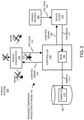
- FIG. 2 is an example diagram illustrating noise reduction control during a sample window of time according to embodiments herein.
- the controller 140 generates control signal 105 at or around a time such as in a window of time in which the monitor 145 performs a sampling of the feedback 171.
- control signal 105 modifies an operation of the respective power converter 120 to reduce or eliminate noise 103 during the window of time. In such an instance, the temporary reduction in the noise 103 enables the monitor 145 to produce more accurate samples 175 of respective feedback 171.
- the device 170 can be any suitable type of hardware, software, etc.
- the device 170 can be a motor controlled by the controller 140.
- the feedback 171 represents an amount of current through one or more respective windings of the motor.
- the controller 140 produces control signal 105 to temporarily adjust operation of the power converter 120 to reduce or eliminate presence of noise 103.
- the feedback 171 can be configured to indicate a magnitude of current supplied by the power source 160 to the device 170.
- the controller 140 adjusts the operation of the power converter 120 (reducing noise 103) to produce more accurate samples 175 of the magnitude of current supplied by the power source 160 to the load (device 170).
- the controller 140 and corresponding drivers are powered by one or more voltages received from the power converter 120.
- the device can be any suitable resource, hardware, etc.
- the device 170 is a sensor device (transducer) operable to monitor a particular parameter such as temperature, pressure, etc.
- the device 170 produces feedback 171 indicating a magnitude of a respective monitored parameter.
- the controller 140 produces control signal 105 to temporarily adjust operation of the power converter 120 to reduce or eliminate presence of noise 103.
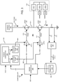
- FIG. 3 is an example diagram illustrating implementation of control and sampling functions according to embodiments herein.
- the power converter 120 includes multiple power conversion resources (hardware) such as power converter 450, charge pump 451, charge pump 452, etc., generating one or more voltages 455, 461, 462, etc.
- power conversion resources such as power converter 450, charge pump 451, charge pump 452, etc.
- the controller 140 includes signal generator 340 as well as multiple phase drivers P1, P2, and P3 that drive respective windings 118-1, 118-2, and 118-3 associated with load 118.
- each of the phase drivers P1, P2, and P3 drives a respective motor winding of load 118 (a.k.a., device 170).
- the power converter 450 produces respective output voltage 455 (such as from a received input voltage).
- the power converter 450 supplies the generated output voltage 455 to each of charge pump 451 and charge pump 452.
- the power converter 450 generates different voltages supplied to the charge pumps 451 and 452.
- the charge pump 451 Based on received voltage 455, the charge pump 451 generates respective output voltage 461 supplied to the driver 415-1 of phase driver P1. Similarly, based on the received voltage 455 (or other suitable voltage generated by the power converter 450), the charge pump 452 generates respective output voltage 462 supplied to the driver 415-2 of phase driver P1.
- the controller 140 such as instantiated as a circuit further includes signal generator 340.
- the signal generator 340 receives control setting 305 indicating how to control current provided to winding 118-1 of the load 118 via phase P1.
- the controller 140 and corresponding monitor 145 determines an amount of current supplied to a winding of the load 118 based on monitoring a respective voltage (feedback 171 such as a single or differential voltage) provided by resistor R10.
- the signal generator 340 generates the signal 106-1 supplied to driver 415-1.
- Driver 415-1 produces control signal 310 that drives high side switch circuitry 491 to an ON-state. While the high side switch circuitry 491 is in an ON state, the low side switch circuitry 492 is controlled to an OFF state based on the input 311 provided by the driver 415-2.
- the signal generator 340 In a second portion of a respective control cycle, the signal generator 340 generates the signal 106-1 supplied to driver 415-1 to be a logic low signal.
- Driver 415-1 produces control signal 310 that drives high side switch circuitry 491 to an OFF state. While the high side switch circuitry 491 is in an OFF state, the low side switch circuitry 492 is controlled to an ON state based on the input 311 provided by the driver 415-2.
- the monitor 145 receives feedback 171 such as indicating an amount of current through a respective winding of the load 118 and produces samples 175 stored in repository 180.
- the signal generator 340 compares the samples 175 to a control setting 305.
- the signal generator 340 varies a respective pulse with of generating corresponding control signals 106-1 and 106-2 to supply the appropriate amount of current to the load 118 via each of the phases P1, P2, P3 as specified by the control setting 305.
- the signal generator 340 increases a pulse width modulation duty cycle of operating high side switch circuitry 491 in a control cycle; if the detected current supplied (as indicated by samples 175) is greater than the setpoint 305, the signal generator 340 decreases a pulse width modulation duty cycle of operating high side switch circuitry 491 in a control cycle.
- the controller 140 can be configured to adjust operation of the power converter 120 in any suitable manner.
- FIG. 4 below illustrates monitoring of the feedback signal 171 without modifying operation of the power converter 120.
- the samples 175 derived from the monitored feedback 171 include a substantial amount of noise caused by continued operation of the power converter 120.
- FIGS. 5 through 8 below illustrate different techniques of adjusting operation of the respective power converter 120 (and one or more of power converter 450, charge pump 451, charge pump 452, etc.) during one or more windows of time to reduce the amount of noise associated with the feedback 171 and corresponding samples 175.
- FIG. 4 is an example timing diagram illustrating feedback affected by noise according to embodiments herein.
- the controller 140 activates the low side switch circuitry 492 to an ON state between time T1 and time T2 via generation of the control signal 106-2 to a high state.
- the controller 140 deactivates the high side switch circuitry 491 to an OFF state between time T1 and time T2 via generation of the control signal 106-1 to a low state.
- the corresponding feedback signal 171 generated by the sense resistor R10 includes unwanted noise 403.
- the monitor 145 monitors the feedback 171 during the windows of time W1, W2, W3, etc., the samples 175 are inaccurate due to the presence of the noise 403 affecting the signal 171 and/or monitor 145 capturing the samples 175.
- FIG. 5 is an example timing diagram illustrating temporary power converter adjustments and sampling of respective feedback according to embodiments herein.
- the controller 140 is operative to receive feedback 171 associated with a device 170 (such as load 118) powered by a power source 160.
- the controller 140 controls delivery of power (such as current) from the power source 160 to the load 118.
- the power converter 120 converts an input voltage and supplies corresponding generated one or more voltages to power the load 118.
- noise 103 from the power converter 120 may itself couple onto the feedback 171 via spikes in the ground voltage
- noise 103 from the power converter 120 may itself couple onto the feedback 171 via spikes in the supply voltages
- a monitor 145 that samples the feedback may be susceptible to noise from the power converter 120, etc.
- the controller 140 adjusts operation of the power converter 120 during a window of time W11 in which the power source 160 powers the device 170.
- the adjusted operation of the power converter 120 during the window of time W11 as shown in FIG. 5 temporarily reduces noise 103 associated with the sampling of feedback 171 caused by the power converter 120 even though the power converter 120 still provides holdup power (such as voltages 455, 461, 462,) to the drivers 415 during the outage.
- the controller 140 or corresponding, monitor, sampler, etc., associated with the controller derives or produces one or more samples values 175 from the feedback 171.
- the signal 170 is clean of noise during window of time W11 because the clock CLK1 is disabled and one or more power converters are disabled.
- the power converter 450 is a buck converter including at least a high-side switch (synchronous switch) and a high-side switch (control switch) that are switched ON and OFF at different times via clock CLK1 to produce the respective output voltage 151.
- the power converter 120 includes one or more switching power supplies.
- the controller 140 generates a control signal 105 at appropriate windows of time (W11, W12, W13, etc.) to control the power converter 120.
- the control signal 105 indicates to temporarily discontinue switching operation of the power converter 120 during windows of time W11, W12, W13, etc.
- the noiseless feedback 171 from the device 170 indicates a parameter such as an amount of current supplied by the power source 160 to the device 170 (such as motor, circuit, etc.), although feedback 171 can be information associated with any suitable monitored parameter.
- the power converter 120 supplies power to the switch drivers 415 controlled by the controller 140.
- the controller 140 controls delivery of the current from the power source 160 to the load 118 and corresponding windings 118-1, 118-2, and 118-3 via one or more switches 491 and 492 driven by the switch drivers 415.
- control signal 105 disables the operation of the power converter 450 such that the output voltage 462 supplied to drivers 415 starts to drop (decrease) at the beginning of a respective window of time.
- the power converter 450 and corresponding charge pumps 451 and 452 include appropriate capacitors to temporarily maintain output voltage 455 and output voltages 461 and 462 above a threshold value during the windows of time W11, W12, W13, etc., although the voltage 462 supplied to the driver 451-2 steadily decreases in each of the windows of time.
- the temporary adjustment of the power converter 120 reduces an amount of the noise 103 in the sample values 175 caused by the power converter 120.
- further embodiments herein include operation of the power converter 120 outside the window of time W11 between the time T11 and time T12.
- the operation of the power converter 120 and corresponding switching introduces noise in the feedback associated with the device 170.
- no samples are taken outside the window of time.
- FIG. 6 is an example timing diagram illustrating temporary power converter adjustments and sampling of respective feedback according to embodiments herein.
- the controller 140 communicates the control signal 105 to the power converter 120 in a similar manner as previously discussed.
- the control signal 105 indicates to temporarily modify a switching frequency of the power conversion (associated with clock CLK1 and power conversion) during each of the windows of time.
- the controller 140 controls the frequency of the clock CLK1 to be a first switching frequency such as 400 KHZ; inside the windows of time W21, W22, W23, etc., the controller 140 controls the frequency of the clock CLK1 to be a first switching frequency such as 100 KHZ.
- the pulse width duration remains the same inside and outside of windows although this can vary.
- the lower frequency of switching the power converters during the windows of time W21, W22, W23, etc. reduces an amount of noise coupling onto the samples 175 derived from the feedback 171. Switching operation in the windows of time ensures that the voltage 462 does network of the drop below a threshold value.
- modification of the switching frequency CLK1 during each of the windows of time at least temporarily reduces an amount of noise originating from the power converter 120 during a respective sample window of time W21, W22, W23, etc., in which the feedback 171 is converted into one or more sample values 175.
- FIG. 7 is an example timing diagram illustrating temporary power converter adjustments and sampling of respective feedback according to embodiments herein.
- Further embodiments herein include, via the controller 140, during each of the windows of time W31, W32, W33, etc., the controller 140 or other suitable entity controls a slew rate of switch control signals (CLK1) used to perform power conversion via the power converter 120.
- the controller 140 controls the slew rate of switching as well as a switching frequency during the windows of time.
- the controller 140 communicates the control signal 105 to the power converter 120 in a similar manner as previously discussed.
- the control signal 105 indicates to temporarily modify a switching frequency of the power conversion (associated with clock CLK1 and power conversion) during each of the windows of time W31, W32, W33, etc.
- the controller 140 also indicates (via control communications) to reduce a respective slew rate of clock CLK1 as shown.
- the controller 140 controls the frequency of the clock CLK1 to be a first switching frequency such as 400 KHZ; the controller 140 controls the frequency of the clock CLK1 to be a first switching frequency such as 100 KHZ.
- the controller 140 reduces the slew (rate at which the clock signal CLK1 takes to rise from a logic low to logic high or drop from a logic high to a logic state) in each of the windows of time.
- the lower frequency of switching the power converters during the windows of time W31, W32, W33, etc. reduces an amount of noise coupling onto the samples 175 derived from the feedback 171.
- modification of the switching frequency CLK1 during each of the windows of time at least temporarily reduces an amount of noise originating from the power converter 120 during a respective sample window of time W31, W32, W33, etc., in which the feedback 171 is converted into one or more sample values.
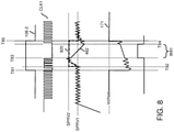
- FIG. 8 is an example timing diagram illustrating temporary setpoint voltage adjustments and sampling of respective feedback according to embodiments herein. Further embodiments herein include mitigating the negative impact of the power converter 120 being switched to an OFF state during a window of time. For example, in one embodiment, the system designer knows how long it takes from activation of the low side switch circuitry 492 via the PWM signal until current is present in the sensor R10 (or other suitable entity) for sampling. In that time, the reference regulation setpoint for the power converter 120 can be artificially increased to a programmable value. After the sampling period arrives according to the controller, the clock is gated and the output of converter typically will drop.
- the controller 140 temporarily adjusts a setpoint regulation voltage of the power converter during each of the windows of time. For example, in one embodiment, as shown at time T82, the controller 140 increases a magnitude of a regulation reference setpoint voltage of the power converter 120 prior to operating a sampler/monitor 145 that produces the one or more sample values 175 from the feedback 171.
- the controller 140 sets the reference voltage to value SPRV1.
- the output voltage 462 produced by the power converter 120 is around the value SPRV1.
- the controller 140 increases a magnitude of the setpoint reference voltage to be value SPRV2.
- the magnitude of the voltage 462 increases to the value SPRV2 between time T82 and time T83.
- the increased magnitude of the regulation reference setpoint voltage to SPRV2 temporarily increases a corresponding magnitude of the output voltage 462 produced by the power converter 120 in an anticipation that the power converter 120 will be temporarily deactivated during the window of time W81.
- the controller 140 During the window of time W81 (time T83 to time T84), the controller 140 generates the control signal 105 which causes the power converter 120 to temporarily discontinue power conversion/switching operations.
- the temporary cessation of the switching and corresponding power conversion via the power converter 120 reduces the effect of noise 103 originated by the power converter on the feedback 171 and corresponding samples 175. In other words, the feedback signal 171 and corresponding generated samples 175 are free from noise 103.
- FIG. 9 is an example diagram illustrating a power system according to embodiments herein.
- the management resource 940 receives gate control signal 905 (such as a pulse width modulation signal) generated by the controller 140.
- the management resource 940 generates controls signals 106 and 105 from the gate control signal 905.
- a respective user is able to define or program delays between signal 905 and control signals 105 and 106.
- the management resource 940 determines when to deactivate the power converter 120.
- Power converter 120 supplies power 930 (such as voltages 461 and 462) to the drivers 415. Deactivation of the power converter 120 reduces or eliminates noise 103, enabling the signal processor 975 (such as an amplifier) and corresponding monitor 145 to convert the received feedback signal 171 from sensor 960 (such as resistor R10) into respective samples 175.
- the gating signal is internal to the device or simply is extracted directly from the signal 905 (such as PWM signal) after some programmable delay in contrast to another device providing the gating information externally. Delays refer to propagation delay of signals like PWM and MOSFET switch on.
- the controller 140 produces a switch control signal 905 to control respective one or more switches in the inverter 950.
- a state of the switches control delivery of the current from a power source 160 to the load 118.
- the switch control signal 905 itself is used to determine the window of time (as defined by control signal 105) modifying a behavior of the power converter 120 in any way as described herein.
- controller 140 monitor 145, gate drivers 415, power converter 120, management resource 940, signal processor 975, etc.
- the components as shown FIG. 9 are individual components.
- embodiments herein are useful over conventional techniques.
- embodiments herein include adjusting operation of a respective power converter in any of multiple different ways to at least temporarily reduce noise 103 originating from the power converter 120.
- the reduction in noise 103 enables a respective monitor/sampler 145 to obtain a more accurate reading of sample value from received feedback 171.
- embodiments herein include selective disabling or altering of the switching of the noise source (converter clock for example) in a way that when the sensing circuitry is needed, the feedback signal is clean.
- the power conversion is selectively adjusted such that the power converter generally performs the desired function of providing power to components of the power system 100 but provides a window of reduced noise from the power converter 120 to generate one or more noise free samples 175.
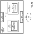
- FIG. 10 is an example block diagram of a computer device for implementing any of the operations as discussed herein according to embodiments herein.
- computer system 1000 (such as implemented by any of one or more resources such as controller 140, monitor 145, power converter 120, etc.) of the present example includes an interconnect 1011 that couples computer readable storage media 1012 such as a non-transitory type of media (or hardware storage media) in which digital information can be stored and retrieved, a processor 1013 (e.g., computer processor hardware such as one or more processor devices), I/O interface 1014, and a communications interface 1017.
- I/O interface 1014 provides connectivity to any suitable circuitry such as power voltage converter 165.
- Computer readable storage medium 1012 can be any hardware storage resource or device such as memory, optical storage, hard drive, floppy disk, etc. In one embodiment, the computer readable storage medium 1012 stores instructions and/or data used by the controller application 140-1 to perform any of the operations as described herein.
- communications interface 1017 enables the computer system 1000 and processor 1013 to communicate over a resource such as network 190 to retrieve information from remote sources and communicate with other computers.
- controller application 140-1 e.g., software, firmware, etc.
- Controller application 140-1 can be configured to include instructions to implement any of the operations as discussed herein.
- processor 1013 accesses computer readable storage media 1012 via the use of interconnect 1011 in order to launch, run, execute, interpret or otherwise perform the instructions in controller application 140-1 stored on computer readable storage medium 1012.
- controller application 140-1 produces processing functionality such as controller process 140-2 in processor 1013.
- controller process 140-2 associated with processor 1013 represents one or more aspects of executing controller application 140-1 within or upon the processor 1013 in the computer system 1000.
- computer system 1000 can be a micro-controller device, logic, hardware processor, hybrid analog/digital circuitry, etc., configured to control a power supply and perform any of the operations as described herein.
- FIG. 11 is an example diagram illustrating a method of controlling a power converter according to embodiments herein.
- the controller 140 receives feedback 171 associated with a device 170 (such as load 118) powered by a power source 160.
- the controller 140 adjusts operation of the power converter 120 during a window of time in which the power source 160 powers the device 170 (such as a load 118).
- the adjusted operation (any techniques as described herein) reduces or eliminates noise 103 caused by the power converter 120.
- the monitor derives a sample value from the feedback 171.
- FIG. 12 is an example diagram illustrating assembly of a power converter circuit (as including one or more power converters) on a circuit board according to embodiments herein.
- assembler 1240 receives a substrate 1010 and corresponding components of power system 100 such as one or more of repository 180, controller 140, power converter 120, power source 160, etc.
- the assembler 1040 affixes (couples) the controller 140 and other components such as a repository 180, controller 140, power converter 120, power source 160, etc., to the substrate 1210.
- the fabricator 1240 provides connectivity between the power converter 120, controller 140, etc.
- components such as the controller 140, power converter 120, monitor 145, load 118, etc., can be affixed or coupled to the substrate 1210 in any suitable manner.
- one or more of the components in power system 100 can be soldered to the substrate 1210, inserted into sockets disposed on the substrate 1210, etc.
- the substrate 1210 is optional. Any of one or more circuit paths or connectivity as shown in the FIGS. and as described herein can be disposed in cables or other suitable medium.
- the load 118 is disposed on its own substrate independent of substrate 1210; the substrate of the load 118 is directly or indirectly connected to the substrate 1210 via wires, cables, links, etc.
- the controller 140 or any portion of the power converter 120 can be disposed on a standalone smaller board plugged into a socket of the substrate 1210 as well.
- the assembler 1240 couples the power system 100 and corresponding components to the load 118.
- the circuit path 1222 conveys the power from power source 160 to the load 118.
- embodiments herein include a system comprising: a substrate 1210 (such as a circuit board, standalone board, mother board, standalone board destined to be coupled to a mother board, host, etc.); a power system 100 including corresponding components as described herein; and a load 118 (such as a motor, winding, etc.).
- a substrate 1210 such as a circuit board, standalone board, mother board, standalone board destined to be coupled to a mother board, host, etc.
- a power system 100 including corresponding components as described herein
- a load 118 such as a motor, winding, etc.
- An algorithm as described herein, and generally, is considered to be a self-consistent sequence of operations or similar processing leading to a desired result.
- operations or processing involve physical manipulation of physical quantities.
- quantities may take the form of electrical or magnetic signals capable of being stored, transferred, combined, compared or otherwise manipulated. It has been convenient at times, principally for reasons of common usage, to refer to such signals as bits, data, values, elements, symbols, characters, terms, numbers, numerals or the like. It should be understood, however, that all of these and similar terms are to be associated with appropriate physical quantities and are merely convenient labels.
Landscapes
- Engineering & Computer Science (AREA)
- Power Engineering (AREA)
- Physics & Mathematics (AREA)
- Electromagnetism (AREA)
- Dc-Dc Converters (AREA)
Abstract
Description
- There are multiple types of switching power converters. For example, one type of conventional power converter is a buck converter. In general, to maintain an output voltage within a desired range, a controller in the buck converter compares the magnitude of a generated output voltage to a setpoint reference voltage. Based on a respective error voltage, the controller modifies a respective switching frequency and/or pulse width modulation associated with activating high side switch circuitry or low side switch circuitry in the buck converter.
- Another type of conventional power converter is a charge pump. In general, charge pumps use some form of switching a respective device to control the connection of a supply voltage across a load through a capacitor. In a two stage cycle charge pump, a respective first stage includes a capacitor that is connected across the supply, charging it to a respective voltage. A second stage of the charge pump couples the capacitor in series with the supply and the load. This doubles the voltage applied to the load. For example, via proper switching, the output voltage of the charge pump is the sum of the original supply and the multiple capacitor voltages.
- Any type of power converter that converts an input voltage into output voltage output signal susceptible to substantial noise due to the power converter switching control. Typically, power converter switching results in abrupt changes in current delivery, resulting in substantial and unwanted noise.
- This disclosure includes the observation that conventional power supply monitoring and control techniques suffer from deficiencies. For example, it is often difficult but desirable to more precisely sense a magnitude of sensor signal such as an output current delivered by a respective power converter to a load in order to generate appropriate control signals. In certain instances, the source of noise coupled into high sensitivity sensing is a power converter that performs high frequency switching. In general, high SR (Slew Rates), meaning high dI/dt and dV/dt of power supply switching current lead to spikes in respective system feedback signals, affecting overall control of a respective device.
- Embodiments herein include novel ways of improving an accuracy of sampling feedback that is susceptible to noise from one or more noise sources such as one or more power converters.
- More specifically, embodiments herein include an apparatus and/or system including a controller. The controller is operative to receive feedback associated with a device powered by a power source. Derivation of a sample from the feedback is susceptible to errors for any number of reasons. For example, noise from a power converter in nearby proximity may couple onto the feedback signal itself, a monitor that samples the feedback may be susceptible to noise from the nearby power converter, etc. In furtherance of reducing noise associated with monitoring the feedback, the controller as described herein adjusts operation of the power converter during a window of time in which the power source powers the device. The adjusted operation of the power converter during the window of time temporarily reduces noise caused by the power converter even though the power converter still provides power such as to control and/or power the device. During the window of time in which the operation of the power converter is adjusted to reduce noise, the controller (or corresponding, monitor, sampler, etc., associated with the controller) derives or produces a sample value from the feedback signal.
- In accordance with further example embodiments, the feedback (such as a feedback signal) indicates a magnitude of current supplied by the power source to the device. The controller adjusts the operation of the power converter to produce a more accurate one or more samples of the magnitude of current supplied by the power source to the load. In one embodiment, the controller is powered by one or more output voltages received (supplied) from the power converter (one or more power converters).
- The controller can be configured to adjust operation of the power converter in any suitable manner. For example, in one embodiment, the power converter is a switching power supply. The controller generates a control signal to control the power converter. In one embodiment, the control signal indicates to temporarily discontinue switching operation of the power converter during the window of time. The feedback from the device indicates an amount of current supplied by the power source to the device (such as motor, circuit, etc.). In one embodiment, the power converter supplies power to a switch driver controlled by the controller. Via controlling operation of the switch driver, the controller controls delivery of the current from the power source to the device via one or more switches driven by the switch driver.
- In yet further example embodiments, the temporary adjustment of the power converter during the window of time (when sampling takes place) reduces an amount of the noise in the sample value caused by the power converter.
- In still further example embodiments, the controller communicates a control signal to the power converter; the control signal indicating to temporarily modify a switching frequency of the power conversion during the window of time. In one embodiment, modification of the switching frequency at least temporarily reduces an amount of noise originating from the power converter during a respective sample window of time in which the feedback is converted into one or more accurate sample values.
- Further embodiments herein include, via the controller, during the window of time, controlling a slew rate of switch control signals used to perform power conversion via the power converter.
- In still further example embodiments, the controller temporarily adjusts a setpoint regulation voltage of the power converter. For example, in one embodiment, the controller increases a magnitude of a regulation reference setpoint voltage of the power converter prior to operating a sampler/monitor that derives one or more sample values from the feedback. The increased magnitude of the regulation reference setpoint voltage temporarily increases a corresponding magnitude of an output voltage produced by the power converter in an anticipation that the power converter will be temporarily deactivated during the window of time but must still provide output power via the output voltage. For example, in one embodiment, the controller generates a control signal. The control signal controls the power converter during the window of time and causes the power converter to temporarily discontinue power conversion/switching operations after increasing the regulation setpoint voltage. The temporary cessation of the switching and corresponding power conversion via the power converter reduces the effect of noise originated by the power converter on the feedback.
- Further embodiments herein include operation of the power converter outside the window of time. In such an instance, the operation of the power converter and corresponding switching introduces noise in the feedback associated with the device. As previously discussed, the adjusted operation of the power converter and respective power conversion during the window of time reduces presence of the noise in the feedback.
- Still further example embodiments herein include, via the controller, producing a switch control signal to control a respective switch, a state of the switch controls delivery of the current from the power source to the device. In one embodiment, the switch control signal itself is used to determine the window of time in which to adjust the operation of the power converter.
- As previously discussed, embodiments herein are useful over conventional techniques. For example, embodiments herein include adjusting operation of a respective power converter in any of multiple different ways to at least temporarily reduce noise originating from the power converter. The reduction in noise enables a respective monitor/sampler to obtain a more accurate reading of one or more sample values generated from received feedback. For example, embodiments herein include selective disabling or altering of the switching of the noise source (converter clock and respective power converter, for example) in a way that when the sensing and sampling circuitry is implemented, the feedback signal is clean. However, the power conversion is selectively adjusted such that the power converter generally performs the desired function of providing power but provides a window of reduced noise from the power converter to generate one or more noise free samples.
- These and other more specific embodiments are disclosed in more detail below.
- Note that although embodiments as discussed herein are applicable to power converters, the concepts disclosed herein may be advantageously applied to any other suitable topologies as well as general power supply control applications.
- Note that any of the resources as discussed herein can include one or more computerized devices, mobile communication devices, servers, base stations, wireless communication equipment, communication management systems, workstations, user equipment, handheld or laptop computers, or the like to carry out and/or support any or all of the method operations disclosed herein. In other words, one or more computerized devices or processors can be programmed and/or configured to operate as explained herein to carry out the different embodiments as described herein.
- Yet other embodiments herein include software programs to perform the steps and operations summarized above and disclosed in detail below. One such embodiment comprises a computer program product including a non-transitory computer-readable storage medium (i.e., any computer readable hardware storage medium) on which software instructions are encoded for subsequent execution. The instructions, when executed in a computerized device (hardware) having a processor, program and/or cause the processor (hardware) to perform the operations disclosed herein. Such arrangements are typically provided as software, code, instructions, and/or other data (e.g., data structures) arranged or encoded on a non-transitory computer readable storage medium such as an optical medium (e.g., CD-ROM), floppy disk, hard disk, memory stick, memory device, etc., or other a medium such as firmware in one or more ROM, RAM, PROM, etc., or as an Application Specific Integrated Circuit (ASIC), etc. The software or firmware or other such configurations can be installed onto a computerized device to cause the computerized device to perform the techniques explained herein.
- Accordingly, embodiments herein are directed to methods, systems, computer program products, etc., that support operations as discussed herein.
- One embodiment herein includes a computer readable storage medium and/or system having instructions stored thereon. The instructions, when executed by computer processor hardware, cause the computer processor hardware (such as one or more co-located or disparately located processor devices) to: receive feedback associated with a device powered by a power source; adjust operation of a power converter during a window of time in which the power source powers the device, the adjusted operation reducing noise caused by the power converter; and during the window of time in which the operation of the power converter is adjusted, derive a sample value from the feedback.
- The ordering of the steps above has been added for clarity sake. Note that any of the processing operations as discussed herein can be performed in any suitable order.
- Other embodiments of the present disclosure include software programs and/or respective hardware to perform any of the method embodiment steps and operations summarized above and disclosed in detail below.
- It is to be understood that the system, method, apparatus, instructions on computer readable storage media, etc., as discussed herein also can be embodied strictly as a software program, firmware, as a hybrid of software, hardware and/or firmware, or as hardware alone such as within a processor (hardware or software), or within an operating system or a within a software application.
- As discussed herein, techniques herein are well suited for use in the field of implementing one or more inductor components to deliver current to a load. However, it should be noted that embodiments herein are not limited to use in such applications and that the techniques discussed herein are well suited for other applications as well.
- Additionally, note that although each of the different features, techniques, configurations, etc., herein may be discussed in different places of this disclosure, it is intended, where suitable, that each of the concepts can optionally be executed independently of each other or in combination with each other. Accordingly, the one or more present inventions as described herein can be embodied and viewed in many different ways.
- Also, note that this preliminary discussion of embodiments herein purposefully does not specify every embodiment and/or incrementally novel aspect of the present disclosure or claimed invention(s). Instead, this brief description only presents general embodiments and corresponding points of novelty over conventional techniques. For additional details and/or possible perspectives (permutations) of the invention(s), the reader is directed to the Detailed Description section (which is a summary of embodiments) and corresponding figures of the present disclosure as further discussed below.
-
FIG. 1 is an example general diagram of a power system supporting power control and feedback monitoring according to embodiments herein. -
FIG. 2 is an example diagram illustrating noise reduction during one or more sample windows of time according to embodiments herein. -
FIG. 3 is a more detailed example diagram illustrating implementation of control and sampling functions and respective circuitry according to embodiments herein. -
FIG. 4 is an example timing diagram illustrating feedback and sampling affected by noise according to embodiments herein. -
FIG. 5 is an example timing diagram illustrating temporary power converter adjustments and sampling of respective feedback according to embodiments herein. -
FIG. 6 is an example timing diagram illustrating temporary power converter adjustments and sampling of respective feedback according to embodiments herein. -
FIG. 7 is an example timing diagram illustrating temporary power converter adjustments and sampling of respective feedback according to embodiments herein. -
FIG. 8 is an example timing diagram illustrating temporary setpoint voltage adjustments and sampling of respective feedback according to embodiments herein. -
FIG. 9 is an example diagram illustrating a power system according to embodiments herein. -
FIG. 10 is an example diagram illustrating computer processor hardware and related software instructions that execute methods according to embodiments herein. -
FIG. 11 is an example diagram illustrating a method according to embodiments herein. -
FIG. 12 is an example diagram illustrating assembly of a circuit according to embodiments herein. - The foregoing and other objects, features, and advantages of the invention will be apparent from the following more particular description of preferred embodiments herein, as illustrated in the accompanying drawings in which like reference characters refer to the same parts throughout the different views. The drawings are not necessarily to scale, with emphasis instead being placed upon illustrating the embodiments, principles, concepts, etc.
- In certain instances, power converters such as buck converter, charge pumps, etc., are integrated with highly sensitive circuits like operation amplifiers, comparators, ADC (Analog to Digital Converters), etc., that are used for sampling feedback voltages. This disclosure includes the observation that power converters or other mid to high frequency switching circuits can induce or couple high unacceptable amounts of switching noise into high precision sensing circuits.
- As an example, in a device where a buck converter is integrated with a current sense amplifier, the buck switching can negatively affect the current sense amplifier in its ability to accurately sense a flow of current or another monitored parameter. Embodiments herein include ensuring that high precision analog parameter sensing and sampling is possible in integrated systems including noisy circuitry such as one or more power converter.
- One embodiment herein includes a controller. The controller receives feedback associated with a device powered by a power source. Sampling of the feedback is susceptible to noise originating from a power converter. To achieve more accurate sampling of the feedback, the controller adjusts operation of the power converter during a window of time in which the power source powers the device. Adjustment of the power converter can include any suitable operation such as discontinued switching of the power converter, reduced switching of the power converter, etc. The adjusted operation of the power converter reduces noise originating from the power converter such that, during the window of time in which the operation of the power converter is adjusted, a corresponding monitor (sampler) of the controller derives a more accurate sample value from received feedback.
- Now, more specifically,
FIG. 1 is an example general diagram of a power system supporting power generation control and feedback monitoring according to embodiments herein. In this example embodiment, the power system ofFIG. 1 includes acontroller 140 andcorresponding monitor 145, power converter 120 (one or more power converters or noise generating circuits),repository 180,power source 160, anddevice 170. - During operation, the power converter 120 (i.e., any noise generating circuit) receives clock signal CLK1. As its name suggests, the power converter 120 (such as one or more power conversion circuits) converts one or more input voltages to one or more output voltages. In this example embodiment, the
power converter 120 producesvoltage 151 supplied tocontroller 140. Thecontroller 140 uses thevoltage 151 to control operation of thedevice 170 viacontrol signal 106. - Note that the
power converter 120 producesnoise 103 via switching of a respective one or more switches in thepower converter 120 to produce thevoltage 151 supplied tocontroller 140 or other suitable entity. - The
noise 103 originating from or caused bypower converter 120 can take any suitable form. For example, in one embodiment, thepower converter 120 andcontroller 140 are in close proximity and are connected to the same ground planes. In such an instance, operation of thepower converter 120 results in coupling ofnoise 103 to the ground plane (voltage perturbations) and corresponding nearby circuitry such ascontroller 140, monitor 145, etc. - The circuitry associated with
controller 140 such as themonitor 145 and corresponding sampling is susceptible to errors or imperfect readings due to presence ofnoise 103. - In addition or as an alternative to
noise 103 affecting ground signals, note that thevoltage 151 itself may includenoise 103 originating from thepower converter 120. - In yet further instances, the
noise 103 may take the form of an emitted wireless signal that couples onto any of one or more of the circuit paths providing connectivity between different components of thepower system 100. In a similar manner, in such an instance, thenoise 103 introduces error to thesamples 175 generated by themonitor 145. - Further in this nonlimiting example embodiment, the
power source 160 provides voltage 161 (power) to thedevice 170. In one embodiment, thepower source 160 powers thedevice 170 viavoltage 161. As an alternative, note that thepower converter 120 optionally supplies power (such as viavoltage 151 or other suitable value) to thedevice 170 in lieu of or in addition to the supply of power from thepower source 160. - As further discussed herein, it is noted that presence of the
noise 103 is undesirable because it affects an accuracy of themonitor 145 producingrespective samples 175 fromfeedback 171. -
FIG. 2 is an example diagram illustrating noise reduction control during a sample window of time according to embodiments herein. In this example embodiment, thecontroller 140 generatescontrol signal 105 at or around a time such as in a window of time in which themonitor 145 performs a sampling of thefeedback 171. - In one embodiment, the
control signal 105 modifies an operation of therespective power converter 120 to reduce or eliminatenoise 103 during the window of time. In such an instance, the temporary reduction in thenoise 103 enables themonitor 145 to produce moreaccurate samples 175 ofrespective feedback 171. - Note that the
device 170 can be any suitable type of hardware, software, etc. For example, in one non-limiting example embodiment, thedevice 170 can be a motor controlled by thecontroller 140. In such an instance, thefeedback 171 represents an amount of current through one or more respective windings of the motor. - In furtherance of producing
accurate samples 175 of corresponding current, thecontroller 140 producescontrol signal 105 to temporarily adjust operation of thepower converter 120 to reduce or eliminate presence ofnoise 103. - Thus, in one embodiment, the
feedback 171 can be configured to indicate a magnitude of current supplied by thepower source 160 to thedevice 170. Thecontroller 140 adjusts the operation of the power converter 120 (reducing noise 103) to produce moreaccurate samples 175 of the magnitude of current supplied by thepower source 160 to the load (device 170). In one embodiment, thecontroller 140 and corresponding drivers are powered by one or more voltages received from thepower converter 120. - Note that the device can be any suitable resource, hardware, etc. For example, in another embodiment, the
device 170 is a sensor device (transducer) operable to monitor a particular parameter such as temperature, pressure, etc. In such an instance, thedevice 170 producesfeedback 171 indicating a magnitude of a respective monitored parameter. In furtherance of producingaccurate samples 175 of corresponding current, thecontroller 140 producescontrol signal 105 to temporarily adjust operation of thepower converter 120 to reduce or eliminate presence ofnoise 103. -
FIG. 3 is an example diagram illustrating implementation of control and sampling functions according to embodiments herein. In this example embodiment, thepower converter 120 includes multiple power conversion resources (hardware) such aspower converter 450,charge pump 451,charge pump 452, etc., generating one or 455, 461, 462, etc.more voltages - Further in this example embodiment, the
controller 140 includessignal generator 340 as well as multiple phase drivers P1, P2, and P3 that drive respective windings 118-1, 118-2, and 118-3 associated withload 118. Thus, in one embodiment, each of the phase drivers P1, P2, and P3 drives a respective motor winding of load 118 (a.k.a., device 170). - As further shown, the
power converter 450 produces respective output voltage 455 (such as from a received input voltage). Thepower converter 450 supplies the generatedoutput voltage 455 to each ofcharge pump 451 andcharge pump 452. Alternatively, thepower converter 450 generates different voltages supplied to the charge pumps 451 and 452. - Based on received
voltage 455, thecharge pump 451 generatesrespective output voltage 461 supplied to the driver 415-1 of phase driver P1. Similarly, based on the received voltage 455 (or other suitable voltage generated by the power converter 450), thecharge pump 452 generatesrespective output voltage 462 supplied to the driver 415-2 of phase driver P1. - In this example embodiment, the
controller 140 such as instantiated as a circuit further includessignal generator 340. - In one embodiment, the
signal generator 340 receives control setting 305 indicating how to control current provided to winding 118-1 of theload 118 via phase P1. Thecontroller 140 andcorresponding monitor 145 determines an amount of current supplied to a winding of theload 118 based on monitoring a respective voltage (feedback 171 such as a single or differential voltage) provided by resistor R10. - More specifically, in a first portion of a respective control cycle, the
signal generator 340 generates the signal 106-1 supplied to driver 415-1. Driver 415-1 produces control signal 310 that drives highside switch circuitry 491 to an ON-state. While the highside switch circuitry 491 is in an ON state, the lowside switch circuitry 492 is controlled to an OFF state based on theinput 311 provided by the driver 415-2. - In a second portion of a respective control cycle, the
signal generator 340 generates the signal 106-1 supplied to driver 415-1 to be a logic low signal. Driver 415-1 produces control signal 310 that drives highside switch circuitry 491 to an OFF state. While the highside switch circuitry 491 is in an OFF state, the lowside switch circuitry 492 is controlled to an ON state based on theinput 311 provided by the driver 415-2. - As previously discussed, the
monitor 145 receivesfeedback 171 such as indicating an amount of current through a respective winding of theload 118 and producessamples 175 stored inrepository 180. - In one embodiment, the
signal generator 340 compares thesamples 175 to a control setting 305. Thesignal generator 340 varies a respective pulse with of generating corresponding control signals 106-1 and 106-2 to supply the appropriate amount of current to theload 118 via each of the phases P1, P2, P3 as specified by the control setting 305. - For example, if the detected current supplied (as indicated by samples 175) is less than the
setpoint 305, thesignal generator 340 increases a pulse width modulation duty cycle of operating highside switch circuitry 491 in a control cycle; if the detected current supplied (as indicated by samples 175) is greater than thesetpoint 305, thesignal generator 340 decreases a pulse width modulation duty cycle of operating highside switch circuitry 491 in a control cycle. - As further discussed below, the
controller 140 can be configured to adjust operation of thepower converter 120 in any suitable manner. For example,FIG. 4 below illustrates monitoring of thefeedback signal 171 without modifying operation of thepower converter 120. In such an instance, thesamples 175 derived from the monitoredfeedback 171 include a substantial amount of noise caused by continued operation of thepower converter 120. -
FIGS. 5 through 8 below illustrate different techniques of adjusting operation of the respective power converter 120 (and one or more ofpower converter 450,charge pump 451,charge pump 452, etc.) during one or more windows of time to reduce the amount of noise associated with thefeedback 171 andcorresponding samples 175. -
FIG. 4 is an example timing diagram illustrating feedback affected by noise according to embodiments herein. In this example embodiment, thecontroller 140 activates the lowside switch circuitry 492 to an ON state between time T1 and time T2 via generation of the control signal 106-2 to a high state. Thecontroller 140 deactivates the highside switch circuitry 491 to an OFF state between time T1 and time T2 via generation of the control signal 106-1 to a low state. - In such an instance, between time T1 and time T2, the corresponding
feedback signal 171 generated by the sense resistor R10 includesunwanted noise 403. Thus, when themonitor 145 monitors thefeedback 171 during the windows of time W1, W2, W3, etc., thesamples 175 are inaccurate due to the presence of thenoise 403 affecting thesignal 171 and/or monitor 145 capturing thesamples 175. -
FIG. 5 is an example timing diagram illustrating temporary power converter adjustments and sampling of respective feedback according to embodiments herein. As previously discussed, thecontroller 140 is operative to receivefeedback 171 associated with a device 170 (such as load 118) powered by apower source 160. Thecontroller 140 controls delivery of power (such as current) from thepower source 160 to theload 118. - In one embodiment, as an alternative to the
power source 160 powering therespective load 118, thepower converter 120 converts an input voltage and supplies corresponding generated one or more voltages to power theload 118. - Also, as previously discussed, note again that derivation of samples from the
feedback 171 is susceptible to errors for any number of reasons. For example, as previously discussed,noise 103 from thepower converter 120 may itself couple onto thefeedback 171 via spikes in the ground voltage,noise 103 from thepower converter 120 may itself couple onto thefeedback 171 via spikes in the supply voltages, amonitor 145 that samples the feedback may be susceptible to noise from thepower converter 120, etc. - In furtherance of reducing noise associated with monitoring the feedback 171 (such as a single voltage or differential voltage from sense resistor R10 or other suitable entity), the
controller 140 adjusts operation of thepower converter 120 during a window of time W11 in which thepower source 160 powers thedevice 170. - For example, the adjusted operation of the
power converter 120 during the window of time W11 as shown inFIG. 5 temporarily reducesnoise 103 associated with the sampling offeedback 171 caused by thepower converter 120 even though thepower converter 120 still provides holdup power (such as 455, 461, 462,) to thevoltages drivers 415 during the outage. More specifically, during the window of time W11 in which the operation of thepower converter 120 is adjusted to reduce noise via discontinued clocking of clock CLK1 and switching inpower converter 120 as shown, the controller 140 (or corresponding, monitor, sampler, etc., associated with the controller) derives or produces one ormore samples values 175 from thefeedback 171. Thesignal 170 is clean of noise during window of time W11 because the clock CLK1 is disabled and one or more power converters are disabled. - In one embodiment, the
power converter 450 is a buck converter including at least a high-side switch (synchronous switch) and a high-side switch (control switch) that are switched ON and OFF at different times via clock CLK1 to produce therespective output voltage 151. - Thus, in one embodiment, as previously discussed, the
power converter 120 includes one or more switching power supplies. Thecontroller 140 generates acontrol signal 105 at appropriate windows of time (W11, W12, W13, etc.) to control thepower converter 120. In one embodiment, thecontrol signal 105 indicates to temporarily discontinue switching operation of thepower converter 120 during windows of time W11, W12, W13, etc. - The
noiseless feedback 171 from thedevice 170 indicates a parameter such as an amount of current supplied by thepower source 160 to the device 170 (such as motor, circuit, etc.), althoughfeedback 171 can be information associated with any suitable monitored parameter. - In one embodiment, the
power converter 120 supplies power to theswitch drivers 415 controlled by thecontroller 140. Via controlling operation of theswitch drivers 415, thecontroller 140 controls delivery of the current from thepower source 160 to theload 118 and corresponding windings 118-1, 118-2, and 118-3 via one or 491 and 492 driven by themore switches switch drivers 415. - In this example embodiment, the
control signal 105 disables the operation of thepower converter 450 such that theoutput voltage 462 supplied todrivers 415 starts to drop (decrease) at the beginning of a respective window of time. Note that thepower converter 450 and corresponding charge pumps 451 and 452 include appropriate capacitors to temporarily maintainoutput voltage 455 and 461 and 462 above a threshold value during the windows of time W11, W12, W13, etc., although theoutput voltages voltage 462 supplied to the driver 451-2 steadily decreases in each of the windows of time. - The temporary adjustment of the power converter 120 (such as discontinued switching of respective high-side switch and low-side switch of a buck converter and switching of charge pumps) during the windows of time (when sampling takes place) reduces an amount of the
noise 103 in the sample values 175 caused by thepower converter 120. - As further shown, further embodiments herein include operation of the
power converter 120 outside the window of time W11 between the time T11 and time T12. In such an instance, the operation of thepower converter 120 and corresponding switching introduces noise in the feedback associated with thedevice 170. In one embodiment, no samples are taken outside the window of time. -
FIG. 6 is an example timing diagram illustrating temporary power converter adjustments and sampling of respective feedback according to embodiments herein. In this embodiment, thecontroller 140 communicates thecontrol signal 105 to thepower converter 120 in a similar manner as previously discussed. However, in this instance, thecontrol signal 105 indicates to temporarily modify a switching frequency of the power conversion (associated with clock CLK1 and power conversion) during each of the windows of time. - For example, outside each of the windows of time W21, W22, W23, etc., the
controller 140 controls the frequency of the clock CLK1 to be a first switching frequency such as 400 KHZ; inside the windows of time W21, W22, W23, etc., thecontroller 140 controls the frequency of the clock CLK1 to be a first switching frequency such as 100 KHZ. The pulse width duration remains the same inside and outside of windows although this can vary. - The lower frequency of switching the power converters during the windows of time W21, W22, W23, etc., reduces an amount of noise coupling onto the
samples 175 derived from thefeedback 171. Switching operation in the windows of time ensures that thevoltage 462 does network of the drop below a threshold value. - Thus, in one embodiment, modification of the switching frequency CLK1 during each of the windows of time at least temporarily reduces an amount of noise originating from the
power converter 120 during a respective sample window of time W21, W22, W23, etc., in which thefeedback 171 is converted into one or more sample values 175. -
FIG. 7 is an example timing diagram illustrating temporary power converter adjustments and sampling of respective feedback according to embodiments herein. Further embodiments herein include, via thecontroller 140, during each of the windows of time W31, W32, W33, etc., thecontroller 140 or other suitable entity controls a slew rate of switch control signals (CLK1) used to perform power conversion via thepower converter 120. In one embodiment, thecontroller 140 controls the slew rate of switching as well as a switching frequency during the windows of time. - Thus, in this example embodiment, in some respects, the
controller 140 communicates thecontrol signal 105 to thepower converter 120 in a similar manner as previously discussed. However, in this instance, thecontrol signal 105 indicates to temporarily modify a switching frequency of the power conversion (associated with clock CLK1 and power conversion) during each of the windows of time W31, W32, W33, etc. Thecontroller 140 also indicates (via control communications) to reduce a respective slew rate of clock CLK1 as shown. - In such an instance, outside each of the windows of time W31, W32, W33, etc., the
controller 140 controls the frequency of the clock CLK1 to be a first switching frequency such as 400 KHZ; thecontroller 140 controls the frequency of the clock CLK1 to be a first switching frequency such as 100 KHZ. Thecontroller 140 reduces the slew (rate at which the clock signal CLK1 takes to rise from a logic low to logic high or drop from a logic high to a logic state) in each of the windows of time. The lower frequency of switching the power converters during the windows of time W31, W32, W33, etc., reduces an amount of noise coupling onto thesamples 175 derived from thefeedback 171. - Thus, in one embodiment, modification of the switching frequency CLK1 during each of the windows of time at least temporarily reduces an amount of noise originating from the
power converter 120 during a respective sample window of time W31, W32, W33, etc., in which thefeedback 171 is converted into one or more sample values. -
FIG. 8 is an example timing diagram illustrating temporary setpoint voltage adjustments and sampling of respective feedback according to embodiments herein. Further embodiments herein include mitigating the negative impact of thepower converter 120 being switched to an OFF state during a window of time. For example, in one embodiment, the system designer knows how long it takes from activation of the lowside switch circuitry 492 via the PWM signal until current is present in the sensor R10 (or other suitable entity) for sampling. In that time, the reference regulation setpoint for thepower converter 120 can be artificially increased to a programmable value. After the sampling period arrives according to the controller, the clock is gated and the output of converter typically will drop. However, because of the overcharging condition of increased setpoint voltage, the drop in voltage will be less than in normal conditions, relaxing the recharge after clock gating and also ensuring average voltage is better regulated. In some cases, this can avoid an UVLO (Under Voltage Low condition) of the converter. - Thus, in still further example embodiments, the
controller 140 temporarily adjusts a setpoint regulation voltage of the power converter during each of the windows of time. For example, in one embodiment, as shown at time T82, thecontroller 140 increases a magnitude of a regulation reference setpoint voltage of thepower converter 120 prior to operating a sampler/monitor 145 that produces the one ormore sample values 175 from thefeedback 171. - More specifically, prior to time T82 and after T85, the
controller 140 sets the reference voltage to value SPRV1. In such an instance, theoutput voltage 462 produced by thepower converter 120 is around the value SPRV1. At or about time T82, thecontroller 140 increases a magnitude of the setpoint reference voltage to be value SPRV2. Thus, because the setpoint voltage controls regulation, the magnitude of thevoltage 462 increases to the value SPRV2 between time T82 and time T83. The increased magnitude of the regulation reference setpoint voltage to SPRV2 temporarily increases a corresponding magnitude of theoutput voltage 462 produced by thepower converter 120 in an anticipation that thepower converter 120 will be temporarily deactivated during the window of time W81. - During the window of time W81 (time T83 to time T84), the
controller 140 generates thecontrol signal 105 which causes thepower converter 120 to temporarily discontinue power conversion/switching operations. The temporary cessation of the switching and corresponding power conversion via thepower converter 120 reduces the effect ofnoise 103 originated by the power converter on thefeedback 171 andcorresponding samples 175. In other words, thefeedback signal 171 and corresponding generatedsamples 175 are free fromnoise 103. -
FIG. 9 is an example diagram illustrating a power system according to embodiments herein. In this example embodiment, themanagement resource 940 receives gate control signal 905 (such as a pulse width modulation signal) generated by thecontroller 140. Themanagement resource 940 generates controls signals 106 and 105 from thegate control signal 905. In one embodiment, a respective user is able to define or program delays betweensignal 905 and 105 and 106.control signals - More specifically, based on the
signal 905, themanagement resource 940 determines when to deactivate thepower converter 120.Power converter 120 supplies power 930 (such asvoltages 461 and 462) to thedrivers 415. Deactivation of thepower converter 120 reduces or eliminatesnoise 103, enabling the signal processor 975 (such as an amplifier) andcorresponding monitor 145 to convert the receivedfeedback signal 171 from sensor 960 (such as resistor R10) intorespective samples 175. In this case, the gating signal is internal to the device or simply is extracted directly from the signal 905 (such as PWM signal) after some programmable delay in contrast to another device providing the gating information externally. Delays refer to propagation delay of signals like PWM and MOSFET switch on. - Thus, in accordance with further example embodiments, the
controller 140 produces aswitch control signal 905 to control respective one or more switches in theinverter 950. A state of the switches control delivery of the current from apower source 160 to theload 118. In this example embodiment, viamanagement resource 940, theswitch control signal 905 itself is used to determine the window of time (as defined by control signal 105) modifying a behavior of thepower converter 120 in any way as described herein. - As further shown, note that the components such as
controller 140, monitor 145,gate drivers 415,power converter 120,management resource 940,signal processor 975, etc., are disposed in anintegrated circuit 999. Alternatively, the components as shownFIG. 9 are individual components. - As previously discussed, embodiments herein are useful over conventional techniques. For example, embodiments herein include adjusting operation of a respective power converter in any of multiple different ways to at least temporarily reduce
noise 103 originating from thepower converter 120. The reduction innoise 103 enables a respective monitor/sampler 145 to obtain a more accurate reading of sample value from receivedfeedback 171. For example, embodiments herein include selective disabling or altering of the switching of the noise source (converter clock for example) in a way that when the sensing circuitry is needed, the feedback signal is clean. However, the power conversion is selectively adjusted such that the power converter generally performs the desired function of providing power to components of thepower system 100 but provides a window of reduced noise from thepower converter 120 to generate one or more noisefree samples 175. -
FIG. 10 is an example block diagram of a computer device for implementing any of the operations as discussed herein according to embodiments herein. As shown, computer system 1000 (such as implemented by any of one or more resources such ascontroller 140, monitor 145,power converter 120, etc.) of the present example includes aninterconnect 1011 that couples computerreadable storage media 1012 such as a non-transitory type of media (or hardware storage media) in which digital information can be stored and retrieved, a processor 1013 (e.g., computer processor hardware such as one or more processor devices), I/O interface 1014, and acommunications interface 1017. - I/
O interface 1014 provides connectivity to any suitable circuitry such as power voltage converter 165. - Computer
readable storage medium 1012 can be any hardware storage resource or device such as memory, optical storage, hard drive, floppy disk, etc. In one embodiment, the computerreadable storage medium 1012 stores instructions and/or data used by the controller application 140-1 to perform any of the operations as described herein. - Further in this example embodiment,
communications interface 1017 enables thecomputer system 1000 andprocessor 1013 to communicate over a resource such asnetwork 190 to retrieve information from remote sources and communicate with other computers. - As shown, computer
readable storage media 1012 is encoded with controller application 140-1 (e.g., software, firmware, etc.) executed byprocessor 1013. Controller application 140-1 can be configured to include instructions to implement any of the operations as discussed herein. - During operation of one embodiment,
processor 1013 accesses computerreadable storage media 1012 via the use ofinterconnect 1011 in order to launch, run, execute, interpret or otherwise perform the instructions in controller application 140-1 stored on computerreadable storage medium 1012. - Execution of the controller application 140-1 produces processing functionality such as controller process 140-2 in
processor 1013. In other words, the controller process 140-2 associated withprocessor 1013 represents one or more aspects of executing controller application 140-1 within or upon theprocessor 1013 in thecomputer system 1000. - In accordance with different embodiments, note that
computer system 1000 can be a micro-controller device, logic, hardware processor, hybrid analog/digital circuitry, etc., configured to control a power supply and perform any of the operations as described herein. - Functionality supported by the different resources will now be discussed via flowchart in
FIG. 11 . Note that the steps in the flowcharts below can be executed in any suitable order. -
FIG. 11 is an example diagram illustrating a method of controlling a power converter according to embodiments herein. Inprocessing operation 1110, thecontroller 140 receivesfeedback 171 associated with a device 170 (such as load 118) powered by apower source 160. - In
processing operation 1120, thecontroller 140 adjusts operation of thepower converter 120 during a window of time in which thepower source 160 powers the device 170 (such as a load 118). The adjusted operation (any techniques as described herein) reduces or eliminatesnoise 103 caused by thepower converter 120. - In
processing operation 1130, during the window of time in which the operation of the power converter is adjusted, the monitor (sampler) derives a sample value from thefeedback 171. -
FIG. 12 is an example diagram illustrating assembly of a power converter circuit (as including one or more power converters) on a circuit board according to embodiments herein. In this example embodiment,assembler 1240 receives a substrate 1010 and corresponding components ofpower system 100 such as one or more ofrepository 180,controller 140,power converter 120,power source 160, etc. The assembler 1040 affixes (couples) thecontroller 140 and other components such as arepository 180,controller 140,power converter 120,power source 160, etc., to thesubstrate 1210. - Via respective circuit paths as described herein, the
fabricator 1240 provides connectivity between thepower converter 120,controller 140, etc. Note that components such as thecontroller 140,power converter 120, monitor 145,load 118, etc., can be affixed or coupled to thesubstrate 1210 in any suitable manner. For example, one or more of the components inpower system 100 can be soldered to thesubstrate 1210, inserted into sockets disposed on thesubstrate 1210, etc. - Note further that the
substrate 1210 is optional. Any of one or more circuit paths or connectivity as shown in the FIGS. and as described herein can be disposed in cables or other suitable medium. - In one nonlimiting example embodiment, the
load 118 is disposed on its own substrate independent ofsubstrate 1210; the substrate of theload 118 is directly or indirectly connected to thesubstrate 1210 via wires, cables, links, etc. Thecontroller 140 or any portion of thepower converter 120 can be disposed on a standalone smaller board plugged into a socket of thesubstrate 1210 as well. - Via one or more circuit paths 1222 (such as one or more traces, cables, connectors, wires, conductors, electrically conductive paths, etc.), the
assembler 1240 couples thepower system 100 and corresponding components to theload 118. In one embodiment, thecircuit path 1222 conveys the power frompower source 160 to theload 118. - Accordingly, embodiments herein include a system comprising: a substrate 1210 (such as a circuit board, standalone board, mother board, standalone board destined to be coupled to a mother board, host, etc.); a
power system 100 including corresponding components as described herein; and a load 118 (such as a motor, winding, etc.). - Some of the aspects explained above are summarized in the following by way of numbered examples.
- Example 1. An apparatus comprising: a controller operative to: receive feedback associated with a device powered by a power source; adjust operation of a power converter during a window of time in which the power source powers the device, the adjusted operation during the window of time operative to reduce noise caused by the power converter; and during the window of time in which the operation of the power converter is adjusted, derive a sample value from the feedback.
- Example 2. The apparatus as in example 1, wherein the feedback indicates a magnitude of current supplied by the power source to the device.
- Example 3. The apparatus as in example 1, wherein the power converter is a switching power supply; and wherein the controller is further operative to: generate a control signal to control the power converter, the control signal indicating to temporarily discontinue switching operation of the power converter during the window of time.
- Example 4. The apparatus as in example 2, wherein the feedback indicates an amount of current supplied by the power source to the device; and wherein the power converter supplies power to a switch driver that controls delivery of the current from the power source to the device via switch.
- Example 5. The apparatus as in example 1, wherein the adjustment of the power converter during the window of time reduces an amount of the noise in the sample value caused by the power converter.
- Example 6. The apparatus as in example 1, wherein the controller is further operative to: communicate a control signal to the power converter, the control signal indicating to temporarily modify a switching frequency of the power conversion during the window of time.
- Example 7. The apparatus as in example 1, wherein the controller is further operative to: during the window of time, control a slew rate of switch control signals used to perform power conversion via the power converter.
- Example 8. The apparatus as in example 1, wherein the controller is further operative to: temporarily increase a magnitude of a regulation reference setpoint voltage of the power converter prior to operating a sampler producing the sample value from the feedback, the increased magnitude of the regulation reference setpoint voltage increasing a corresponding magnitude of an output voltage produced by the power converter.
- Example 9. The apparatus as in example 8, wherein the controller is further operative to: generate a control signal, the control signal operative to control the power converter during the window of time, the control signal indicating to temporarily discontinue power conversion switching operations of the power converter during the window of time.
- Example 10. The apparatus as in example 1, wherein operation of the power converter outside the window of time introduces noise in the feedback associated with the device; and wherein the adjusted operation of the power converter conversion during the window of time reduces presence of the noise in the feedback.
- Example 11. The apparatus as in example 1, wherein the controller is further operative to: produce a switch control signal to control a switch, a state of the switch controlling delivery of the current from the power source to the device.
- Example 12. The apparatus as in example 10, wherein the switch control signal is used to determine the window of time in which to adjust the operation of the power converter.
- Example 13. A method comprising: receiving feedback associated with a device powered by a power source; adjusting operation of a power converter during a window of time in which the power source powers the device, the adjusted operation reducing noise caused by the power converter; and during the window of time in which the operation of the power converter is adjusted, deriving a sample value from the feedback.
- Example 14. The method as in example 13, wherein the feedback indicates a magnitude of current supplied by the power source to the device.
- Example 15. The method as in example 13, wherein the power converter is a switching power supply; and wherein adjusting operation of the power converter during the window of time includes: generating a control signal to control the power converter, the control signal indicating to temporarily discontinue switching operation of the power converter during the window of time.
- Example 16. The method as in example 14, wherein the feedback indicates an amount of current supplied by the power source to the device; and wherein the power converter supplies power to a switch driver that controls delivery of the current from the power source to the device via switch.
- Example 17. The method as in example 13, wherein adjusting operation of the power converter during the window of time includes: reducing an amount of noise in the sample value caused by the power converter.
- Example 18. The method as in example 13, wherein adjusting operation of the power converter during the window of time includes: communicating a control signal to the power converter, the control signal indicating to temporarily modify a switching frequency of the power converter conversion during the window of time.
- Example 19. The method as in example 13, wherein adjusting operation of the power converter includes: during the window of time, controlling a slew rate of switch control signals used to perform power conversion via the power converter.
- Example 20. The method as in example 13 , wherein adjusting operation of the power converter during the window of time includes: temporarily increasing a magnitude of a regulation reference setpoint voltage of the power converter prior to operating a sampler producing the sample value from the feedback, the increased magnitude of the regulation reference setpoint voltage increasing a corresponding magnitude of an output voltage produced by the power converter.
- Example 21. The method as in example 20, wherein adjusting operation of the power converter during the window of time includes: generating a control signal, the control signal operative to control the power converter during the window of time, the control signal indicating to temporarily discontinue power conversion switching operations of the power converter during the window of time.
- Example 22. The method as in example 13, wherein operation of the power converter outside the window of time introduces noise in the feedback associated with the device; and wherein the adjusted operation of the power converter conversion during the window of time reduces presence of the noise in the feedback.
- Example 23. The method as in example 13, wherein adjusting operation of the power converter during the window of time includes: producing a switch control signal to control a switch, a state of the switch controlling delivery of the current from the power source to the device.
- Example 24. The method as in example 23 further comprising: using the switch control signal to determine the window of time in which to adjust the operation of the power converter.
- Example 25. Computer-readable storage media having instructions stored thereon, the instructions, when executed by computer processor hardware, cause the computer processor hardware to: receive feedback associated with a device powered by a power source; adjust operation of a power converter during a window of time in which the power source powers the device, the adjusted operation reducing noise caused by the power converter; and during the window of time in which the operation of the power converter is adjusted, derive a sample value from the feedback.
- Example 26. A system comprising: a circuit substrate; the apparatus of example 1, the apparatus coupled to the circuit substrate; and wherein the load is coupled to the substrate.
- Example 27. A method comprising: receiving a circuit substrate; and coupling the apparatus of example 1 to the circuit substrate.
- Note again that techniques herein are well suited for use in circuit applications such as those that implement feedback monitoring. However, it should be noted that embodiments herein are not limited to use in such applications and that the techniques discussed herein are well suited for other applications as well.
- Based on the description set forth herein, numerous specific details have been set forth to provide a thorough understanding of claimed subject matter. However, it will be understood by those skilled in the art that claimed subject matter may be practiced without these specific details. In other instances, methods, apparatuses, systems, etc., that would be known by one of ordinary skill have not been described in detail so as not to obscure claimed subject matter. Some portions of the detailed description have been presented in terms of algorithms or symbolic representations of operations on data bits or binary digital signals stored within a computing system memory, such as a computer memory. These algorithmic descriptions or representations are examples of techniques used by those of ordinary skill in the data processing arts to convey the substance of their work to others skilled in the art. An algorithm as described herein, and generally, is considered to be a self-consistent sequence of operations or similar processing leading to a desired result. In this context, operations or processing involve physical manipulation of physical quantities. Typically, although not necessarily, such quantities may take the form of electrical or magnetic signals capable of being stored, transferred, combined, compared or otherwise manipulated. It has been convenient at times, principally for reasons of common usage, to refer to such signals as bits, data, values, elements, symbols, characters, terms, numbers, numerals or the like. It should be understood, however, that all of these and similar terms are to be associated with appropriate physical quantities and are merely convenient labels. Unless specifically stated otherwise, as apparent from the following discussion, it is appreciated that throughout this specification discussions utilizing terms such as "processing," "computing," "calculating," "determining" or the like refer to actions or processes of a computing platform, such as a computer or a similar electronic computing device, that manipulates or transforms data represented as physical electronic or magnetic quantities within memories, registers, or other information storage devices, transmission devices, or display devices of the computing platform.
Claims (14)
- An apparatus comprising:
a controller (140) operative to:receive feedback (171) associated with a device (170) powered by a power source (160);adjust operation of a power converter (120) during a window of time in which the power source (160) powers the device (170), the adjusted operation during the window of time operative to reduce noise caused by the power converter (120); andduring the window of time in which the operation of the power converter (120) is adjusted, derive a sample value from the feedback. - The apparatus as in claim 1, wherein the feedback (171) indicates a magnitude of current supplied by the power source (160) to the device (170).
- The apparatus as in claim 1, wherein the power converter (120) is a switching power supply; and
wherein the controller (140) is further operative to: generate a control signal (106) to control the power converter (120), the control signal (106) indicating to temporarily discontinue switching operation of the power converter (120) during the window of time. - The apparatus as in claim 2, wherein the feedback (171) indicates an amount of current supplied by the power source (160) to the device (170); and
wherein the power converter (120) supplies power to at least one switch driver (415-1, 415-2) that controls delivery of the current from the power source (160) to the device (170) via at least one switch (491, 492). - The apparatus as in any one of claims 1 to 4, wherein the adjustment of the power converter (120) during the window of time reduces an amount of the noise in the sample value caused by the power converter (120).
- The apparatus as in any one of claims 1 to 5, wherein the controller (140) is further operative to:
communicate a control signal (105) to the power converter (120), the control signal (105) indicating to temporarily modify a switching frequency of the power conversion during the window of time. - The apparatus as in any one of claims 1 to 6, wherein the controller (140) is further operative to:
during the window of time, control a slew rate of switch control signals (CLK1) used to perform power conversion via the power converter (120). - The apparatus as in any one of claims 1 to 7, wherein the controller (140) is further operative to:
temporarily increase a magnitude of a regulation reference setpoint voltage (305) of the power converter prior to operating a sampler (145) producing the sample value from the feedback (171), the increased magnitude of the regulation reference setpoint voltage (305) increasing a corresponding magnitude of an output voltage (462) produced by the power converter (120). - The apparatus as in claim 8, wherein the controller (140) is further operative to:
generate a control signal (105), the control signal (105) operative to control the power converter (120) during the window of time, the control signal (105) indicating to temporarily discontinue power conversion switching operations of the power converter (120) during the window of time. - The apparatus as in claim 1, wherein operation of the power converter (120) outside the window of time introduces noise in the feedback (171) associated with the device (170); and
wherein the adjusted operation of the power converter conversion during the window of time reduces presence of the noise in the feedback (171). - The apparatus as in any one of claims 1 to 10, wherein the controller (140) is further operative to: produce a switch control signal (905) to control a switch, a state of the switch controlling delivery of the current from the power source to the device.
- The apparatus as in claim 10, wherein the switch control signal (905) is used to determine the window of time in which to adjust the operation of the power converter (120).
- A method comprising:receiving feedback (171) associated with a device (170) powered by a power source (160);adjusting operation of a power converter (120) during a window of time in which the power source (160) powers the device (170), the adjusted operation reducing noise caused by the power converter (120); andduring the window of time in which the operation of the power converter (120) is adjusted, deriving a sample value from the feedback (171).
- A system comprising:a circuit substrate (1210);the apparatus of any one of claims 1 to 12, the apparatus coupled to the circuit substrate (1210); andwherein the device (118) is coupled to the substrate (1210).
Applications Claiming Priority (1)
| Application Number | Priority Date | Filing Date | Title |
|---|---|---|---|
| US16/990,360 US11722056B2 (en) | 2020-08-11 | 2020-08-11 | Power converter control and parameter sampling |
Publications (1)
| Publication Number | Publication Date |
|---|---|
| EP3955445A1 true EP3955445A1 (en) | 2022-02-16 |
Family
ID=79554228
Family Applications (1)
| Application Number | Title | Priority Date | Filing Date |
|---|---|---|---|
| EP21190614.4A Pending EP3955445A1 (en) | 2020-08-11 | 2021-08-10 | Power converter control with reduced emi at sampling points |
Country Status (3)
| Country | Link |
|---|---|
| US (1) | US11722056B2 (en) |
| EP (1) | EP3955445A1 (en) |
| CN (1) | CN114079366A (en) |
Families Citing this family (1)
| Publication number | Priority date | Publication date | Assignee | Title |
|---|---|---|---|---|
| JP7427159B2 (en) * | 2019-08-28 | 2024-02-05 | 株式会社オートネットワーク技術研究所 | DCDC converter |
Citations (3)
| Publication number | Priority date | Publication date | Assignee | Title |
|---|---|---|---|---|
| DE10302602A1 (en) * | 2002-01-23 | 2003-08-07 | Toyota Motor Co Ltd | Inverter for an AC generator motor |
| US20200036289A1 (en) * | 2018-07-27 | 2020-01-30 | Asahi Kasei Microdevices Corporation | Integrated circuit and motor device |
| DE102019125753A1 (en) * | 2018-09-26 | 2020-03-26 | Infineon Technologies Ag | Power stage and method for charging a power transistor |
Family Cites Families (9)
| Publication number | Priority date | Publication date | Assignee | Title |
|---|---|---|---|---|
| US4524412A (en) * | 1983-06-06 | 1985-06-18 | At&T Bell Laboratories | Peak current controlled converter with additional current threshold control level to limit current tailout during overload conditions |
| US7265601B2 (en) * | 2004-08-23 | 2007-09-04 | International Rectifier Corporation | Adaptive gate drive voltage circuit |
| US8319486B2 (en) * | 2008-06-13 | 2012-11-27 | The Regents Of The University Of Colorado | Method, apparatus and system for extended switched-mode controller |
| US8305053B2 (en) * | 2010-08-18 | 2012-11-06 | Texas Instruments Incorporated | System and method for controlling a power switch in a power supply system |
| US9584115B2 (en) * | 2014-06-17 | 2017-02-28 | Texas Instruments Incorporated | Duty cycle-controlled load switch |
| US9716437B2 (en) * | 2015-12-18 | 2017-07-25 | Champion Microelectronic Corporation | Power converter for a switching power supply and manner of operation thereof |
| CN106130325B (en) * | 2016-07-13 | 2019-06-18 | 成都芯源系统有限公司 | Noise reduction switch converter, control circuit and method |
| US10186945B1 (en) * | 2017-06-30 | 2019-01-22 | Empower Semiconductor | Resonant switching regulator with continuous current |
| US20200195121A1 (en) * | 2018-12-13 | 2020-06-18 | Texas Instruments Incorporated | Dynamically adjustable gate driver for switching devices and related methods |
-
2020
- 2020-08-11 US US16/990,360 patent/US11722056B2/en active Active
-
2021
- 2021-08-10 CN CN202110912231.XA patent/CN114079366A/en active Pending
- 2021-08-10 EP EP21190614.4A patent/EP3955445A1/en active Pending
Patent Citations (3)
| Publication number | Priority date | Publication date | Assignee | Title |
|---|---|---|---|---|
| DE10302602A1 (en) * | 2002-01-23 | 2003-08-07 | Toyota Motor Co Ltd | Inverter for an AC generator motor |
| US20200036289A1 (en) * | 2018-07-27 | 2020-01-30 | Asahi Kasei Microdevices Corporation | Integrated circuit and motor device |
| DE102019125753A1 (en) * | 2018-09-26 | 2020-03-26 | Infineon Technologies Ag | Power stage and method for charging a power transistor |
Also Published As
| Publication number | Publication date |
|---|---|
| CN114079366A (en) | 2022-02-22 |
| US20220052603A1 (en) | 2022-02-17 |
| US11722056B2 (en) | 2023-08-08 |
Similar Documents
| Publication | Publication Date | Title |
|---|---|---|
| US11515794B2 (en) | Current estimation in a power supply | |
| US11532986B2 (en) | Multi-stage power converter with transformless switched-capacitor converter and control | |
| US11689103B2 (en) | Power supply monitoring and switching frequency control | |
| US11804777B2 (en) | Power supply and emulated current mode control | |
| US12009745B2 (en) | Power supply configurations and non-linear control, switching period adjustment and current control based on error signal | |
| US11601052B2 (en) | Current emulation in a power supply | |
| US11929679B2 (en) | Power supply configurations and PWM edge control | |
| EP4092894A1 (en) | Power supply monitoring and switching control | |
| US11177730B2 (en) | On-time compensation in a power converter | |
| EP3955445A1 (en) | Power converter control with reduced emi at sampling points | |
| US11835550B2 (en) | Power conversion, fault management, and notification | |
| KR101883708B1 (en) | Constant on-time(cot) control in isolated converter | |
| WO2011152225A1 (en) | Design support device and design support method of gate drive circuit | |
| EP3985856A1 (en) | Multi-dimensional pulse width modulation control | |
| US12003179B2 (en) | Power supply and emulated current mode to control generation of an output voltage | |
| US11404961B2 (en) | On-time compensation in a power converter | |
| KR101915057B1 (en) | Constant on-time(cot) control in isolated converter | |
| EP3754825B1 (en) | Power supply apparatus and control method thereof | |
| KR20170045327A (en) | Constant on-time(cot) control in isolated converter | |
| US11581832B2 (en) | Motor winding monitoring and switching control |
Legal Events
| Date | Code | Title | Description |
|---|---|---|---|
| PUAI | Public reference made under article 153(3) epc to a published international application that has entered the european phase |
Free format text: ORIGINAL CODE: 0009012 |
|
| STAA | Information on the status of an ep patent application or granted ep patent |
Free format text: STATUS: THE APPLICATION HAS BEEN PUBLISHED |
|
| AK | Designated contracting states |
Kind code of ref document: A1 Designated state(s): AL AT BE BG CH CY CZ DE DK EE ES FI FR GB GR HR HU IE IS IT LI LT LU LV MC MK MT NL NO PL PT RO RS SE SI SK SM TR |
|
| STAA | Information on the status of an ep patent application or granted ep patent |
Free format text: STATUS: REQUEST FOR EXAMINATION WAS MADE |
|
| 17P | Request for examination filed |
Effective date: 20220808 |
|
| RBV | Designated contracting states (corrected) |
Designated state(s): AL AT BE BG CH CY CZ DE DK EE ES FI FR GB GR HR HU IE IS IT LI LT LU LV MC MK MT NL NO PL PT RO RS SE SI SK SM TR |
|
| STAA | Information on the status of an ep patent application or granted ep patent |
Free format text: STATUS: EXAMINATION IS IN PROGRESS |
|
| 17Q | First examination report despatched |
Effective date: 20240314 |