EP3955415A1 - Power management device, power management system, and power management method - Google Patents
Power management device, power management system, and power management method Download PDFInfo
- Publication number
- EP3955415A1 EP3955415A1 EP20788386.9A EP20788386A EP3955415A1 EP 3955415 A1 EP3955415 A1 EP 3955415A1 EP 20788386 A EP20788386 A EP 20788386A EP 3955415 A1 EP3955415 A1 EP 3955415A1
- Authority
- EP
- European Patent Office
- Prior art keywords
- user
- power
- output
- visit
- electric power
- Prior art date
- Legal status (The legal status is an assumption and is not a legal conclusion. Google has not performed a legal analysis and makes no representation as to the accuracy of the status listed.)
- Withdrawn
Links
Images




Classifications
-
- H—ELECTRICITY
- H02—GENERATION; CONVERSION OR DISTRIBUTION OF ELECTRIC POWER
- H02J—ELECTRIC POWER NETWORKS; CIRCUIT ARRANGEMENTS OR SYSTEMS FOR SUPPLYING OR DISTRIBUTING ELECTRIC POWER; SYSTEMS FOR STORING ELECTRIC ENERGY
- H02J3/00—Circuit arrangements for AC mains or AC distribution networks
- H02J3/38—Arrangements for feeding a single network from two or more generators or sources in parallel; Arrangements for feeding already energised networks from additional generators or sources in parallel
- H02J3/381—Dispersed generators
-
- B—PERFORMING OPERATIONS; TRANSPORTING
- B60—VEHICLES IN GENERAL
- B60L—PROPULSION OF ELECTRICALLY-PROPELLED VEHICLES; SUPPLYING ELECTRIC POWER FOR AUXILIARY EQUIPMENT OF ELECTRICALLY-PROPELLED VEHICLES; ELECTRODYNAMIC BRAKE SYSTEMS FOR VEHICLES IN GENERAL; MAGNETIC SUSPENSION OR LEVITATION FOR VEHICLES; MONITORING OPERATING VARIABLES OF ELECTRICALLY-PROPELLED VEHICLES; ELECTRIC SAFETY DEVICES FOR ELECTRICALLY-PROPELLED VEHICLES
- B60L53/00—Methods of charging batteries, specially adapted for electric vehicles; Charging stations or on-board charging equipment therefor; Exchange of energy storage elements in electric vehicles
- B60L53/60—Monitoring or controlling charging stations
- B60L53/66—Data transfer between charging stations and vehicles
- B60L53/665—Methods related to measuring, billing or payment
-
- B—PERFORMING OPERATIONS; TRANSPORTING
- B60—VEHICLES IN GENERAL
- B60L—PROPULSION OF ELECTRICALLY-PROPELLED VEHICLES; SUPPLYING ELECTRIC POWER FOR AUXILIARY EQUIPMENT OF ELECTRICALLY-PROPELLED VEHICLES; ELECTRODYNAMIC BRAKE SYSTEMS FOR VEHICLES IN GENERAL; MAGNETIC SUSPENSION OR LEVITATION FOR VEHICLES; MONITORING OPERATING VARIABLES OF ELECTRICALLY-PROPELLED VEHICLES; ELECTRIC SAFETY DEVICES FOR ELECTRICALLY-PROPELLED VEHICLES
- B60L53/00—Methods of charging batteries, specially adapted for electric vehicles; Charging stations or on-board charging equipment therefor; Exchange of energy storage elements in electric vehicles
- B60L53/60—Monitoring or controlling charging stations
- B60L53/68—Off-site monitoring or control, e.g. remote control
-
- G—PHYSICS
- G05—CONTROLLING; REGULATING
- G05B—CONTROL OR REGULATING SYSTEMS IN GENERAL; FUNCTIONAL ELEMENTS OF SUCH SYSTEMS; MONITORING OR TESTING ARRANGEMENTS FOR SUCH SYSTEMS OR ELEMENTS
- G05B15/00—Systems controlled by a computer
- G05B15/02—Systems controlled by a computer electric
-
- H—ELECTRICITY
- H02—GENERATION; CONVERSION OR DISTRIBUTION OF ELECTRIC POWER
- H02J—ELECTRIC POWER NETWORKS; CIRCUIT ARRANGEMENTS OR SYSTEMS FOR SUPPLYING OR DISTRIBUTING ELECTRIC POWER; SYSTEMS FOR STORING ELECTRIC ENERGY
- H02J13/00—Circuit arrangements for providing remote monitoring or remote control of equipment in a power distribution network
- H02J13/12—Monitoring network conditions, e.g. electrical magnitudes or operational status
-
- H—ELECTRICITY
- H02—GENERATION; CONVERSION OR DISTRIBUTION OF ELECTRIC POWER
- H02J—ELECTRIC POWER NETWORKS; CIRCUIT ARRANGEMENTS OR SYSTEMS FOR SUPPLYING OR DISTRIBUTING ELECTRIC POWER; SYSTEMS FOR STORING ELECTRIC ENERGY
- H02J13/00—Circuit arrangements for providing remote monitoring or remote control of equipment in a power distribution network
- H02J13/13—Circuit arrangements for providing remote monitoring or remote control of equipment in a power distribution network characterised by the transmission of data to equipment in the power network
-
- H—ELECTRICITY
- H02—GENERATION; CONVERSION OR DISTRIBUTION OF ELECTRIC POWER
- H02J—ELECTRIC POWER NETWORKS; CIRCUIT ARRANGEMENTS OR SYSTEMS FOR SUPPLYING OR DISTRIBUTING ELECTRIC POWER; SYSTEMS FOR STORING ELECTRIC ENERGY
- H02J13/00—Circuit arrangements for providing remote monitoring or remote control of equipment in a power distribution network
- H02J13/14—Circuit arrangements for providing remote monitoring or remote control of equipment in a power distribution network the power network being locally controlled, e.g. home energy management systems [HEMS]
-
- H—ELECTRICITY
- H02—GENERATION; CONVERSION OR DISTRIBUTION OF ELECTRIC POWER
- H02J—ELECTRIC POWER NETWORKS; CIRCUIT ARRANGEMENTS OR SYSTEMS FOR SUPPLYING OR DISTRIBUTING ELECTRIC POWER; SYSTEMS FOR STORING ELECTRIC ENERGY
- H02J3/00—Circuit arrangements for AC mains or AC distribution networks
- H02J3/008—Circuit arrangements for power supply or distribution technologies responsive to energy trading
-
- H—ELECTRICITY
- H02—GENERATION; CONVERSION OR DISTRIBUTION OF ELECTRIC POWER
- H02J—ELECTRIC POWER NETWORKS; CIRCUIT ARRANGEMENTS OR SYSTEMS FOR SUPPLYING OR DISTRIBUTING ELECTRIC POWER; SYSTEMS FOR STORING ELECTRIC ENERGY
- H02J3/00—Circuit arrangements for AC mains or AC distribution networks
- H02J3/28—Arrangements for balancing of the load in networks by storage of energy
- H02J3/32—Arrangements for balancing of the load in networks by storage of energy using batteries or super capacitors with converting means
- H02J3/322—Arrangements for balancing of the load in networks by storage of energy using batteries or super capacitors with converting means the battery being on-board an electric or hybrid vehicle, e.g. vehicle to grid arrangements [V2G], power aggregation, use of the battery for network load balancing, coordinated or cooperative battery charging
-
- B—PERFORMING OPERATIONS; TRANSPORTING
- B60—VEHICLES IN GENERAL
- B60L—PROPULSION OF ELECTRICALLY-PROPELLED VEHICLES; SUPPLYING ELECTRIC POWER FOR AUXILIARY EQUIPMENT OF ELECTRICALLY-PROPELLED VEHICLES; ELECTRODYNAMIC BRAKE SYSTEMS FOR VEHICLES IN GENERAL; MAGNETIC SUSPENSION OR LEVITATION FOR VEHICLES; MONITORING OPERATING VARIABLES OF ELECTRICALLY-PROPELLED VEHICLES; ELECTRIC SAFETY DEVICES FOR ELECTRICALLY-PROPELLED VEHICLES
- B60L53/00—Methods of charging batteries, specially adapted for electric vehicles; Charging stations or on-board charging equipment therefor; Exchange of energy storage elements in electric vehicles
- B60L53/60—Monitoring or controlling charging stations
- B60L53/66—Data transfer between charging stations and vehicles
-
- H—ELECTRICITY
- H02—GENERATION; CONVERSION OR DISTRIBUTION OF ELECTRIC POWER
- H02J—ELECTRIC POWER NETWORKS; CIRCUIT ARRANGEMENTS OR SYSTEMS FOR SUPPLYING OR DISTRIBUTING ELECTRIC POWER; SYSTEMS FOR STORING ELECTRIC ENERGY
- H02J2101/00—Supply or distribution of decentralised, dispersed or local electric power generation
- H02J2101/20—Dispersed power generation using renewable energy sources
- H02J2101/22—Solar energy
- H02J2101/24—Photovoltaics
-
- H—ELECTRICITY
- H02—GENERATION; CONVERSION OR DISTRIBUTION OF ELECTRIC POWER
- H02J—ELECTRIC POWER NETWORKS; CIRCUIT ARRANGEMENTS OR SYSTEMS FOR SUPPLYING OR DISTRIBUTING ELECTRIC POWER; SYSTEMS FOR STORING ELECTRIC ENERGY
- H02J7/00—Circuit arrangements for charging or discharging batteries or for supplying loads from batteries
- H02J7/34—Parallel operation in networks using both storage and other DC sources, e.g. providing buffering
- H02J7/35—Parallel operation in networks using both storage and other DC sources, e.g. providing buffering with light sensitive cells
-
- Y—GENERAL TAGGING OF NEW TECHNOLOGICAL DEVELOPMENTS; GENERAL TAGGING OF CROSS-SECTIONAL TECHNOLOGIES SPANNING OVER SEVERAL SECTIONS OF THE IPC; TECHNICAL SUBJECTS COVERED BY FORMER USPC CROSS-REFERENCE ART COLLECTIONS [XRACs] AND DIGESTS
- Y02—TECHNOLOGIES OR APPLICATIONS FOR MITIGATION OR ADAPTATION AGAINST CLIMATE CHANGE
- Y02E—REDUCTION OF GREENHOUSE GAS [GHG] EMISSIONS, RELATED TO ENERGY GENERATION, TRANSMISSION OR DISTRIBUTION
- Y02E10/00—Energy generation through renewable energy sources
- Y02E10/50—Photovoltaic [PV] energy
- Y02E10/56—Power conversion systems, e.g. maximum power point trackers
-
- Y—GENERAL TAGGING OF NEW TECHNOLOGICAL DEVELOPMENTS; GENERAL TAGGING OF CROSS-SECTIONAL TECHNOLOGIES SPANNING OVER SEVERAL SECTIONS OF THE IPC; TECHNICAL SUBJECTS COVERED BY FORMER USPC CROSS-REFERENCE ART COLLECTIONS [XRACs] AND DIGESTS
- Y02—TECHNOLOGIES OR APPLICATIONS FOR MITIGATION OR ADAPTATION AGAINST CLIMATE CHANGE
- Y02E—REDUCTION OF GREENHOUSE GAS [GHG] EMISSIONS, RELATED TO ENERGY GENERATION, TRANSMISSION OR DISTRIBUTION
- Y02E60/00—Enabling technologies; Technologies with a potential or indirect contribution to GHG emissions mitigation
-
- Y—GENERAL TAGGING OF NEW TECHNOLOGICAL DEVELOPMENTS; GENERAL TAGGING OF CROSS-SECTIONAL TECHNOLOGIES SPANNING OVER SEVERAL SECTIONS OF THE IPC; TECHNICAL SUBJECTS COVERED BY FORMER USPC CROSS-REFERENCE ART COLLECTIONS [XRACs] AND DIGESTS
- Y02—TECHNOLOGIES OR APPLICATIONS FOR MITIGATION OR ADAPTATION AGAINST CLIMATE CHANGE
- Y02T—CLIMATE CHANGE MITIGATION TECHNOLOGIES RELATED TO TRANSPORTATION
- Y02T10/00—Road transport of goods or passengers
- Y02T10/60—Other road transportation technologies with climate change mitigation effect
- Y02T10/70—Energy storage systems for electromobility, e.g. batteries
-
- Y—GENERAL TAGGING OF NEW TECHNOLOGICAL DEVELOPMENTS; GENERAL TAGGING OF CROSS-SECTIONAL TECHNOLOGIES SPANNING OVER SEVERAL SECTIONS OF THE IPC; TECHNICAL SUBJECTS COVERED BY FORMER USPC CROSS-REFERENCE ART COLLECTIONS [XRACs] AND DIGESTS
- Y02—TECHNOLOGIES OR APPLICATIONS FOR MITIGATION OR ADAPTATION AGAINST CLIMATE CHANGE
- Y02T—CLIMATE CHANGE MITIGATION TECHNOLOGIES RELATED TO TRANSPORTATION
- Y02T10/00—Road transport of goods or passengers
- Y02T10/60—Other road transportation technologies with climate change mitigation effect
- Y02T10/7072—Electromobility specific charging systems or methods for batteries, ultracapacitors, supercapacitors or double-layer capacitors
-
- Y—GENERAL TAGGING OF NEW TECHNOLOGICAL DEVELOPMENTS; GENERAL TAGGING OF CROSS-SECTIONAL TECHNOLOGIES SPANNING OVER SEVERAL SECTIONS OF THE IPC; TECHNICAL SUBJECTS COVERED BY FORMER USPC CROSS-REFERENCE ART COLLECTIONS [XRACs] AND DIGESTS
- Y02—TECHNOLOGIES OR APPLICATIONS FOR MITIGATION OR ADAPTATION AGAINST CLIMATE CHANGE
- Y02T—CLIMATE CHANGE MITIGATION TECHNOLOGIES RELATED TO TRANSPORTATION
- Y02T90/00—Enabling technologies or technologies with a potential or indirect contribution to GHG emissions mitigation
- Y02T90/10—Technologies relating to charging of electric vehicles
- Y02T90/12—Electric charging stations
-
- Y—GENERAL TAGGING OF NEW TECHNOLOGICAL DEVELOPMENTS; GENERAL TAGGING OF CROSS-SECTIONAL TECHNOLOGIES SPANNING OVER SEVERAL SECTIONS OF THE IPC; TECHNICAL SUBJECTS COVERED BY FORMER USPC CROSS-REFERENCE ART COLLECTIONS [XRACs] AND DIGESTS
- Y02—TECHNOLOGIES OR APPLICATIONS FOR MITIGATION OR ADAPTATION AGAINST CLIMATE CHANGE
- Y02T—CLIMATE CHANGE MITIGATION TECHNOLOGIES RELATED TO TRANSPORTATION
- Y02T90/00—Enabling technologies or technologies with a potential or indirect contribution to GHG emissions mitigation
- Y02T90/10—Technologies relating to charging of electric vehicles
- Y02T90/16—Information or communication technologies improving the operation of electric vehicles
-
- Y—GENERAL TAGGING OF NEW TECHNOLOGICAL DEVELOPMENTS; GENERAL TAGGING OF CROSS-SECTIONAL TECHNOLOGIES SPANNING OVER SEVERAL SECTIONS OF THE IPC; TECHNICAL SUBJECTS COVERED BY FORMER USPC CROSS-REFERENCE ART COLLECTIONS [XRACs] AND DIGESTS
- Y02—TECHNOLOGIES OR APPLICATIONS FOR MITIGATION OR ADAPTATION AGAINST CLIMATE CHANGE
- Y02T—CLIMATE CHANGE MITIGATION TECHNOLOGIES RELATED TO TRANSPORTATION
- Y02T90/00—Enabling technologies or technologies with a potential or indirect contribution to GHG emissions mitigation
- Y02T90/10—Technologies relating to charging of electric vehicles
- Y02T90/16—Information or communication technologies improving the operation of electric vehicles
- Y02T90/167—Systems integrating technologies related to power network operation and communication or information technologies for supporting the interoperability of electric or hybrid vehicles, i.e. smartgrids as interface for battery charging of electric vehicles [EV] or hybrid vehicles [HEV]
-
- Y—GENERAL TAGGING OF NEW TECHNOLOGICAL DEVELOPMENTS; GENERAL TAGGING OF CROSS-SECTIONAL TECHNOLOGIES SPANNING OVER SEVERAL SECTIONS OF THE IPC; TECHNICAL SUBJECTS COVERED BY FORMER USPC CROSS-REFERENCE ART COLLECTIONS [XRACs] AND DIGESTS
- Y04—INFORMATION OR COMMUNICATION TECHNOLOGIES HAVING AN IMPACT ON OTHER TECHNOLOGY AREAS
- Y04S—SYSTEMS INTEGRATING TECHNOLOGIES RELATED TO POWER NETWORK OPERATION, COMMUNICATION OR INFORMATION TECHNOLOGIES FOR IMPROVING THE ELECTRICAL POWER GENERATION, TRANSMISSION, DISTRIBUTION, MANAGEMENT OR USAGE, i.e. SMART GRIDS
- Y04S10/00—Systems supporting electrical power generation, transmission or distribution
- Y04S10/12—Monitoring or controlling equipment for energy generation units, e.g. distributed energy generation [DER] or load-side generation
- Y04S10/126—Monitoring or controlling equipment for energy generation units, e.g. distributed energy generation [DER] or load-side generation the energy generation units being or involving electric vehicles [EV] or hybrid vehicles [HEV], i.e. power aggregation of EV or HEV, vehicle to grid arrangements [V2G]
-
- Y—GENERAL TAGGING OF NEW TECHNOLOGICAL DEVELOPMENTS; GENERAL TAGGING OF CROSS-SECTIONAL TECHNOLOGIES SPANNING OVER SEVERAL SECTIONS OF THE IPC; TECHNICAL SUBJECTS COVERED BY FORMER USPC CROSS-REFERENCE ART COLLECTIONS [XRACs] AND DIGESTS
- Y04—INFORMATION OR COMMUNICATION TECHNOLOGIES HAVING AN IMPACT ON OTHER TECHNOLOGY AREAS
- Y04S—SYSTEMS INTEGRATING TECHNOLOGIES RELATED TO POWER NETWORK OPERATION, COMMUNICATION OR INFORMATION TECHNOLOGIES FOR IMPROVING THE ELECTRICAL POWER GENERATION, TRANSMISSION, DISTRIBUTION, MANAGEMENT OR USAGE, i.e. SMART GRIDS
- Y04S30/00—Systems supporting specific end-user applications in the sector of transportation
- Y04S30/10—Systems supporting the interoperability of electric or hybrid vehicles
- Y04S30/12—Remote or cooperative charging
-
- Y—GENERAL TAGGING OF NEW TECHNOLOGICAL DEVELOPMENTS; GENERAL TAGGING OF CROSS-SECTIONAL TECHNOLOGIES SPANNING OVER SEVERAL SECTIONS OF THE IPC; TECHNICAL SUBJECTS COVERED BY FORMER USPC CROSS-REFERENCE ART COLLECTIONS [XRACs] AND DIGESTS
- Y04—INFORMATION OR COMMUNICATION TECHNOLOGIES HAVING AN IMPACT ON OTHER TECHNOLOGY AREAS
- Y04S—SYSTEMS INTEGRATING TECHNOLOGIES RELATED TO POWER NETWORK OPERATION, COMMUNICATION OR INFORMATION TECHNOLOGIES FOR IMPROVING THE ELECTRICAL POWER GENERATION, TRANSMISSION, DISTRIBUTION, MANAGEMENT OR USAGE, i.e. SMART GRIDS
- Y04S30/00—Systems supporting specific end-user applications in the sector of transportation
- Y04S30/10—Systems supporting the interoperability of electric or hybrid vehicles
- Y04S30/14—Details associated with the interoperability, e.g. vehicle recognition, authentication, identification or billing
Definitions
- the present disclosure relates to a power management apparatus, a power management system, and a power management method.
- Patent Literature 1 JP 2011-180791 A
- a power management apparatus includes a management unit configured to manage data of output power output from a distributed power supply provided at a predetermined facility, a detection unit configured to detect that a user in possession of the distributed power supply is present in a visit space other than the predetermined facility, and a control unit configured to perform, when the user is present in the visit space, interchange processing of providing the output power to the visit space based on the data of the output power, the interchange processing including processing of supplying electric power to the user in the visit space.
- a power management method includes managing data of output power output from a distributed power supply provided at a predetermined facility, detecting that a user in possession of the distributed power supply is present in a visit space other than the predetermined facility, and performing, when the user is present in the visit space, interchange processing of providing the output power to the visit space based on the data of the output power, the interchange processing including processing of supplying electric power to the user in the visit space.
- a power management system 100 includes a user facility 10, a visit space 20, a power management apparatus 30, and a user medium 50 carried by a user 40.
- the user facility 10 is an example of a predetermined facility provided with a solar cell device 11.
- the solar cell device 11 is an example of a distributed power supply provided in the user facility 10.
- the solar cell device 11 is also an example of a power generation device that generates electric power by utilizing natural energy.
- the user facility 10 may include an energy management system (EMS) 12 that manages electric power of the user facility 10.
- the EMS 12 may be provided by a cloud service.
- the EMS 12 has a function of communicating with at least the power management apparatus 30.
- the user facility 10 may be a house owned by the user 40 or an organization (company or school) to which the user 40 belongs.
- the user facility 10 may include the power selling facility.
- the user facility 10 is not limited thereto, and the user facility 10 need only include the solar cell device 11.
- the solar cell device 11 may be owned by the user 40 or may be lent to the user 40. In other words, the user 40 need only be a representative person having a right related to the output power of the solar cell device 11.
- the EMS 12 communicates with a device provided in the user facility 10 (for example, the distributed power supply such as the solar cell device 11), or communicates with a sensor that detects electric power of the device provided in the user facility 10.
- the EMS 12 may transmit, to the power management apparatus 30, data (hereinafter referred to as output power data) of output power output from the solar cell device 11.
- the EMS 12 may transmit position information of the user medium 50 to the power management apparatus 30 by communicating with the user medium 50.
- the position information of the user medium 50 may be transmitted directly from the user medium 50 to the power management apparatus 30.
- the user facility 10 may have a power storage device 13 and a station 14.
- the power storage device 13 is a device for storing electric power. In other words, the power storage device 13 may store surplus power obtained by subtracting electric power consumed at the user facility 10 from electric power output from the solar cell device 11.
- the power storage device 13 may store electric power supplied from a power system in a time period (for example, nighttime) during which the fee of electric power to be supplied from the power system is lower than a threshold value.
- the station 14 is an apparatus configured to charge an electric vehicle (EV) 60.
- the station 14 may charge the EV 60 by using electric power output from the solar cell device 11, may charge the EV 60 by using electric power supplied from the power system, or may charge the EV 60 by using electric power output from the power storage device 13.
- the EV 60 may be a private car owned by the user 40. In the case where the EV 60 is charged by using electric power output from the solar cell device 11, the electric power used for charging the EV 60 may be included in electric power consumed at the user
- the visit space 20 is a space that the user 40 may visit.
- the visit space 20 may be a space that includes a station 21 provided at a location different from that of the user facility 10.
- the visit space 20 may be a space where a distance from the station 21 is shorter than or equal to a threshold value (for example, a certain range with the station 21 as a center, premises of a parking lot where the station 21 is provided, premises of a facility such as a convenience store where the station 21 is provided, or the like).
- the visit space 20 may be regarded as the station 21.
- the station 21 is a device capable of charging the EV 60.
- the power management apparatus 30 manages data (the output power data described above) of the output power output from the solar cell device 11.
- the output power may be electric power that flows in a reverse direction from the user facility 10 to a power system.
- the output power may be surplus power obtained by subtracting electric power consumed at the user facility 10 from the electric power output from the solar cell device 11.
- the power management apparatus 30 performs interchange processing based on the output power data. Details of the power management apparatus 30 will be described later (see FIG. 2 ).
- the user 40 is an example of a user that is in possession of at least the solar cell device 11.
- the user 40 may own the user facility 10.
- the user medium 50 need only be a medium carried by the user 40.
- the user medium 50 may be a terminal such as a smartphone or a tablet, or may be an IC card such as a credit card or a point card.
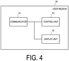
- a case in which the user medium 50 is a smartphone is primarily used as an example. Details of the user medium 50 will be described later (see FIG. 4 ).
- the power management apparatus 30 is connected to the user facility 10 (here, the user facility 10 includes the EMS 12, same applies hereafter) via a network.
- the power management apparatus 30 may be connected to the station 21 via a network.
- the power management apparatus 30 may be connected to the user medium 50 and the EV 60 via a network.
- the network may include the Internet, and may include a mobile communication network.
- the network may include a virtual private network (VPN).
- VPN virtual private network
- the power management apparatus 30 includes a communicator 31, a management unit 32, and a control unit 33.
- the communicator 31 is configured of a communication module.
- the communication module may be a wireless communication module compliant with standards such as IEEE 802.11a/b/g/n, ZigBee, Wi-SUN, LTE, 5G, and 6G, or may be a wired communication module compliant with standards such as IEEE 802.3.
- the communicator 31 receives the output power data from the user facility 10.
- the communicator 31 may periodically receive the output power data from the user facility 10, or may receive the output power data from the user facility 10 in response to a request by the power management apparatus 30 (the control unit 33).
- the communicator 31 may receive the output power data from the user facility 10 in response to identifying proximity to the visit space 20. After proximity to the visit space 20 is identified by the user medium 50, information of the proximity may be transmitted from the user medium 50 to the power management apparatus 30. Proximity to the visit space 20 may be identified based on the position information received from the user medium 50.
- the output power data may include an instantaneous value of the output power (value of instantaneous power), or may include an integrated value of the output power (value of integrated electric power).
- the communicator 31 may transmit, to the user medium 50, data of a value (hereinafter, referred to as value data) corresponding to the power interchange to be described below.
- the communicator 31 may receive, from the station 21, information indicating that the user medium 50 is connected to the station 21 by short-range wireless communication and that the user medium 50 has requested that the station 21 perform power interchange.
- the short-range wireless communication may include radio frequency identification (RFID) such as near field communication (NFC), or may include barcode reading.
- RFID radio frequency identification
- NFC near field communication
- the communicator 31 is an example of a detection unit that detects that the user 40 is present in the visit space 20 excluding the user facility 10.
- the management unit 32 is configured of a storage medium such as a memory including a non-volatile memory, a hard disc drive (HDD) and/or the like, and stores various types of information.
- a storage medium such as a memory including a non-volatile memory, a hard disc drive (HDD) and/or the like, and stores various types of information.
- the management unit 32 manages the data (hereinafter, referred to as management data) shown in FIG. 3 .
- the management data includes IDs and output power.
- the IDs and the output power are examples of the output power data.
- the ID is information for identifying at least one of the user facility 10 and the solar cell device 11.
- the management data may include position information.
- the position information includes information indicating the visit space 20 in which the user 40 is present.
- the position information may include information indicating that the user 40 is present in the user facility 10.
- the position information may include information indicating that the user 40 is present in neither the user facility 10 nor the visit space 20.
- the position information may be identified based on information received from an EMS 21 or the user medium 50.
- the control unit 33 may include at least one processor.
- the at least one processor may be configured of a single integrated circuit (IC) or a plurality of circuits (such as integrated circuits and/or discrete circuits) connected so as to be capable of communicating with each other.
- the control unit 33 When the user 40 is present in the visit space 20, the control unit 33 performs interchange processing of providing the output power to the visit space 20 based on the output power data.
- the interchange processing is processing of providing the output power from the user facility 10 to the visit space 20, and includes, for example, processing that will be described below.
- the interchange processing may include processing of supplying electric power to the user 40 in the visit space 20 (hereinafter, referred to as power supply processing). Specifically, electric power is supplied to the user 40 in the visit space 20 within a range that does not exceed an upper limit of output power that is output from the solar cell device 11.
- the electric power to be supplied to the user 40 in the visit space 20 may be subtracted from the output power output from the solar cell device 11 rather than being borne by a management entity of the visit space 20 (hereinafter, simply referred to as "management entity").
- management entity the management entity of the visit space 20
- the user 40, the power management apparatus 30, and the management entity may all perform cancellation processing on the electric power consumed at the visit destination.
- an amount of money with which the user 40 purchases electric power from the management entity may be the same as or smaller than an amount of money at which the user 40 sells electric power to the power management apparatus 30.
- An amount of money with which the management entity purchases electric power from the power management apparatus 30 may be different from an amount of money at which the management entity sells electric power to the user 40.
- the power supply processing may be processing of charging the EV 60 with electric power supplied from the station 21.
- the electric power consumed at the visit destination is electric power to be charged to the EV 60 from the station 21.
- the electric power to be charged from the station 21 to the EV 60 may be larger than electric power to be provided in the interchange processing (that is, the electric power consumed at the visit destination).
- An amount of differential electric power between the electric power to be charged from the station 21 to the EV 60 and the electric power to be provided in the interchange processing is supplied from the power system connected to the station 21.
- a right associated with the electric power consumed at the visit destination may be transferred from the user 40 to the management entity.
- the right associated with the electric power consumed at the visit destination may include at least one of the fact that the output power has been output from the solar cell device 11, and an environmental added value associated with the output power (for example, a tradable green certificate).
- control unit 33 may assign a value corresponding to the power interchange to the user 40.
- control unit 33 may transmit the value data to the user medium 50 by controlling the communicator 31.
- the value to be assigned to the user 40 may be a value corresponding to at least one of the electric power consumed at the visit destination and the right associated with the electric power consumed at the visit destination.
- the form of the value may be money, or may be points that are exchangeable for a product, a service, or money.
- the money may be a legal currency or a virtual currency.
- the money or points may be stored in the user medium 50 as value data (electronic data).
- the control unit 33 may set the value to be assigned to the user 40 based on at least one of the electric power consumed at the visit destination and the right associated with the electric power consumed at the visit destination. For example, the control unit 33 may set a higher value for greater electric power consumed at the visit destination. For example, the control unit 33 may set a higher value for a higher environmental added value associated with the electric power consumed at the visit destination.
- the user medium 50 includes a communicator 51, a display unit 52, and a control unit 53.
- the communicator 51 is configured of a communication module.
- the communication module may be a wireless communication module compliant with standards such as IEEE 802.11a/b/g/n, ZigBee, Wi-SUN, LTE, 5G, and 6G, or may be a wired communication module compliant with standards such as IEEE 802.3.
- the communicator 51 may receive the output power data from the user facility 10.
- the data (the value data described above) of the value corresponding to the power interchange may be received from the power management apparatus 30.
- the communicator 51 may transmit the fact of requesting the power interchange to the station 21 or the power management apparatus 30.
- the communicator 51 may transmit the fact of having completed the power interchange to the station 21 or the power management apparatus 30.
- the display unit 52 includes a panel such as a liquid crystal panel or an organic EL panel.
- the display unit 52 may include a touch panel.
- the display unit 52 may display the output power data.
- the display unit 52 may display the right related to the output power.
- the display unit 52 may display information (for example, a level of the output power or the environmental added value) for setting the content of the right related to the output power.
- the display unit 52 may display the value to be assigned by the interchange processing.
- the control unit 53 may include at least one processor.
- the at least one processor may be configured of a single integrated circuit (IC) or a plurality of circuits (such as integrated circuits and/or discrete circuits) connected so as to be capable of communicating with each other.
- the control unit 53 may control an image to be displayed on the display unit 52 based on information received by the communicator 51.
- the control unit 53 may control the communicator 51 based on an operation of the user based on the image displayed on the display unit 52.
- step S11 the user facility 10 transmits the output power data to the power management apparatus 30.
- the user facility 10 periodically transmits the output power data that is managed (or stored) by the EMS 12 to the power management apparatus 30.
- step S12 the power management apparatus 30 manages the output power data.
- step S13 the user medium 50 transmits a request for the power interchange (an interchange request in FIG. 5 ) to the station 21.
- the interchange request may include identification information of the user medium 50, or may include position information of the user medium 50.
- step S14 the station 21 transmits a request for the power interchange (an interchange request in FIG. 5 ) to the power management apparatus 30.
- the interchange request may include identification information of the station 21, position information of the station 21, the identification information of the user medium 50, or the position information of the user medium 50.
- step S15 the power management apparatus 30 performs interchange processing of providing the output power from the user facility 10 to the visit space 20.
- the interchange processing is processing of supplying electric power to the user 40 in the visit space 20.
- the station 21 uses the electric power provided in the interchange processing to charge the EV 60.
- step S17 the station 21 transmits, to the power management apparatus 30, the fact that the power interchange is complete (interchange completion in FIG. 5 ).
- the interchange completion may include the identification information of the station 21, the position information of the station 21, the identification information of the user medium 50, or the position information of the user medium 50.
- step S18 the power management apparatus 30 sets the value to be assigned to the user 40, and transmits the value data described above to the user medium 50.
- the method of setting the value is as described above.
- step S17 for example, when the station 21 notifies the power management apparatus 30 of the "interchange completion" for reporting completion of charging, the user medium 50 is notified of the value data in step S18, and as a result, the user can know the completion of charging.
- a charge completion notification may be transmitted from the EV 60 to the station 21, for example.
- the power management apparatus 30 when the user 40 is present in the visit space 20, the power management apparatus 30 performs the interchange processing of providing the output power to the visit space 20 based on the output power data.
- the interchange processing includes the power supply processing.
- the output power output from the solar cell device 11 provided at the user facility 10 can be used as the electric power consumed at the visit destination in the visit space 20, and the user 40 can freely utilize the output power in terms of bringing the output power output from the solar cell device 11 to the visit space 20.
- the interchange processing includes transferring the right associated with the electric power consumed at the visit destination
- the management entity can contribute to the environment by assigning the value to the user 40 in return for obtaining an environmental added value from the user 40.
- a Modification Example 1 of the embodiment will be described below. In the following, differences from the embodiment will be mainly described.
- the EV 60 is a private car owned by the user 40.
- the EV 60 is an electric vehicle supplied by two or more users (so-called "car sharing").
- the output power output from the solar cell device 11 provided at the user facility 10 is provided to the visit space 20, and the EV 60 is charged using the electric power supplied from the station 21 in the visit space 20. Details of the interchange processing are similar to those of the embodiment.
- the station 21 may be provided at the hub of the car sharing (for example, at a parking lot). In such a case, the station 21 may have a function of performing a function (for example, user authentication) for performing processing of initiating or ending the car sharing. Alternatively, the station 21 may be provided at a location other than the hub of the car sharing. In such a case, the station 21 may be managed by a business operator having a partnership with a business operator of the car sharing.
- the EV 60 may be an electric vehicle that is rented out by a business operator to the user 40 (car rental).
- a case of charging the EV 60 in the visit space 20 is described as an example of the power supply processing.
- Modification Example 2 a case in which the visit space 20 is a facility other than the user facility 10 will be described.
- the visit space 20 is a visit facility 22 other than the user facility 10.
- the visit facility 22 may be a facility of an acquaintance of the user 40, or may be a facility (for example, a company or school) to which the user 40 commutes.
- the interchange processing is processing in which the output power output from the solar cell device 11 provided at the user facility 10 is provided as electric power to be consumed by the user 40 at the visit facility 22 (that is, the electric power consumed at the visit destination).
- all the output power output from the solar cell device 11 may be considered as being provided to the visit facility 22 while the user 40 is present at the visit facility 22.
- predetermined electric power included in the output power output from the solar cell device 11 may be considered as being provided to the visit facility 22.
- the predetermined electric power may be defined by specified electric power, or may be defined by a specified percentage with respect to the output power.
- the electric power provided to the visit facility 22 may be provided free of charge, or may be provided at a charge. Further, a value corresponding to the power interchange may be assigned to the user 40.
- electric power corresponding to the electric power consumed at the visit destination may be considered as being provided to the visit facility 22.
- the electric power corresponding to the electric power consumed at the visit destination may be provided free of charge, or may be provided at a charge.
- a value corresponding to the power interchange may be assigned to the user 40.
- all the output power output from the solar cell device 11 may be considered as being provided to the visit facility 22 while the user 40 is present at the visit facility 22.
- predetermined electric power included in the output power output from the solar cell device 11 may be considered as being provided to the visit facility 22.
- the predetermined electric power may be defined by specified electric power, or may be defined by a specified percentage with respect to the output power.
- the electric power provided to the visit facility 22 may be provided free of charge, or may be provided at a charge.
- the electric power corresponding to the electric power consumed at the visit destination may be provided free of charge, and differential electric power between the electric power to be provided to the visit facility 22 and the electric power consumed at the visit destination may be provided at a charge. Further, a value corresponding to the power interchange may be assigned to the user 40.
- a Modification Example 3 of the embodiment will be described below. In the following, differences from the embodiment will be mainly described.
- the visit space 20 may be a space inside a moving body that uses electricity as an energy source.
- the visit space 20 is a space inside an electric bus 23 that uses electricity as an energy source.
- the interchange processing is processing in which the output power output from the solar cell device 11 provided at the user facility 10 is provided as some of the electric power consumed by the electric bus 23.
- Predetermined electric power included in the output power output from the solar cell device 11 may be considered as being provided to the electric bus 23.
- the predetermined electric power may be defined by specified electric power, or may be defined by a specified percentage with respect to the output power.
- An amount of money corresponding to the electric power to be provided to the electric bus 23 may be subtracted from a fare of the electric bus 23. Further, a value corresponding to the power interchange may be assigned to the user 40.
- all the output power output from the solar cell device 11 may be provided to the electric bus 23 while the user 40 is riding on the electric bus 23.
- the moving body that uses electricity as an energy source may be a moving body such as an aircraft, a ship, a taxi, or a train, in addition to the electric bus 23.
- a Modification Example 4 of the embodiment will be described below. In the following, differences from the embodiment will be mainly described.
- the distributed power supply is the solar cell device 11.
- the distributed power supply may include a power supply other than the solar cell device 11.
- the distributed power supply may include a fuel cell device.
- the fuel cell device may be a solid oxide fuel cell (SOFC), a polymer electrolyte fuel cell (PEFC), a phosphoric acid fuel cell (PAFC), or a molten carbonate fuel cell (MCFC).
- SOFC solid oxide fuel cell
- PEFC polymer electrolyte fuel cell
- PAFC phosphoric acid fuel cell
- MCFC molten carbonate fuel cell
- the power generation device that generates electric power by utilizing natural energy may include any one of a wind power generation device, a geothermal power generation device, and a hydroelectric power generation device.
- the natural energy may also be referred to as renewable energy.
- the two or more distributed power supplies may include the solar cell device 11.
- a Modification Example 5 of the embodiment will be described below. In the following, differences from the embodiment will be mainly described.
- the user 40 having the distributed power supply is a representative person who has the right related to the output power of the solar cell device 11.
- the distributed power supply may be owned by the user 40 or may be lent to the user 40.
- the distributed power supply (solar cell device 11) is owned by a third party
- an aspect may be included in which the distributed power supply is lent to the user 40.
- the third party may be a business operator operating the power management apparatus 30 described above.
- Such a business operator may be an operator such as a power generation utility, a power transmission and distribution utility, a power retailer, or a resource aggregator.
- the third party may receive, from the user 40, a price (electricity fee) for electric power consumed at the user facility 10.
- the interchange processing may be performed on surplus power obtained by subtracting electric power consumed at the user facility 10 from electric power output from the solar cell device 11.
- a value corresponding to the interchange processing may be assigned to the user 40.
- the third party may receive from the user 40, of the electric power output from the solar cell device 11, a price for electric power provided by the interchange processing.
- the user facility 10 may be based on a concept that includes an apartment block configured of two or more residential units, a concept that includes a building occupied by two or more tenants, or a concept that includes multiple facilities connected to a microgrid.
- the method of assigning a value to the user 40 is a method of sending value data to the user medium 50.
- a value corresponding to the interchange processing may be assigned to means other than the user medium 50.
- the value may be assigned as points managed by a management entity.
- the medium to which the value is assigned may be a credit card or a point card, or may be a server managed by the management entity.
- the power management apparatus 30 may transmit the value data to the management entity.
- an electric power provider that manages the user facility 10 may be different from an electric power provider that manages the visit space 20.
- the electric power provider may be a business operator such as a power generation utility, a power transmission/distribution utility, an electricity retailer, or a resource aggregator.
- the resource aggregator is an electric power provider that provides electric power that flows in a reverse direction to a power generation utility, a power transmission/distribution utility, an electricity retailer, or the like in a virtual power plant (VPP).
- VPP virtual power plant
- the electric power may be instantaneous power (kW) or integrated electric power (kWh).
- the output power data may include instantaneous power (kW) or integrated electric power (kWh).
- the value corresponding to the interchange processing may be determined based on the integrated electric power (kWh) of the electric power provided by the interchange processing.
- the program may be recorded in a computer-readable medium.
- the computer-readable medium on which the program is recorded may be a non-transitory recording medium.
- the non-transitory recording medium is not particularly limited and may be, for example, a recording medium such as a CD-ROM or a DVD-ROM.
- a chip configured of a memory that stores a program for executing each process to be performed by the power management apparatus 30 or the user medium 50 and a processor that executes the program stored in the memory may be provided.
- JP 2019-76542 filed on April 12, 2019
- JP 2019-95424 filed on May 21, 2019
Landscapes
- Engineering & Computer Science (AREA)
- Power Engineering (AREA)
- Transportation (AREA)
- Mechanical Engineering (AREA)
- General Engineering & Computer Science (AREA)
- Physics & Mathematics (AREA)
- General Physics & Mathematics (AREA)
- Automation & Control Theory (AREA)
- Supply And Distribution Of Alternating Current (AREA)
- Remote Monitoring And Control Of Power-Distribution Networks (AREA)
- Management, Administration, Business Operations System, And Electronic Commerce (AREA)
Abstract
Description
- The present disclosure relates to a power management apparatus, a power management system, and a power management method.
- In recent years, power generation devices that utilize natural energy such as sunlight, wind power, hydropower, and geothermal heat have attracted attention. A technology has been proposed in which output power output from a power generation device is converted into a predetermined value (valuable points or credit), and the predetermined value is assigned to a terminal (such as an IC card or a mobile phone) of a user who owns the power generation device (for example, Patent Literature 1).
- Patent Literature 1:
JP 2011-180791 A - A power management apparatus according to a first aspect includes a management unit configured to manage data of output power output from a distributed power supply provided at a predetermined facility, a detection unit configured to detect that a user in possession of the distributed power supply is present in a visit space other than the predetermined facility, and a control unit configured to perform, when the user is present in the visit space, interchange processing of providing the output power to the visit space based on the data of the output power, the interchange processing including processing of supplying electric power to the user in the visit space.
- A power management method according to a second aspect includes managing data of output power output from a distributed power supply provided at a predetermined facility, detecting that a user in possession of the distributed power supply is present in a visit space other than the predetermined facility, and performing, when the user is present in the visit space, interchange processing of providing the output power to the visit space based on the data of the output power, the interchange processing including processing of supplying electric power to the user in the visit space.
-
-
FIG. 1 is a diagram illustrating apower management system 100 according to an embodiment. -
FIG. 2 is a diagram illustrating apower management apparatus 30 according to the embodiment. -
FIG. 3 is a table showing an example of management data according to the embodiment. -
FIG. 4 is a diagram illustrating auser medium 50 according to the embodiment. -
FIG. 5 is a diagram illustrating a power management method according to the embodiment. -
FIG. 6 is a diagram illustrating thepower management system 100 according to Modification Example 1. -
FIG. 7 is a diagram illustrating thepower management system 100 according to Modification Example 2. -
FIG. 8 is a diagram illustrating thepower management system 100 according to Modification Example 3. - Embodiments will be described below with reference to the drawings. Note that in the following description of the drawings, identical or similar components will be denoted by identical or similar reference signs. However, the drawings are schematic.
- A power management system according to an embodiment will be described below. As illustrated in
FIG. 1 , apower management system 100 includes auser facility 10, avisit space 20, apower management apparatus 30, and auser medium 50 carried by auser 40. - The
user facility 10 is an example of a predetermined facility provided with asolar cell device 11. Thesolar cell device 11 is an example of a distributed power supply provided in theuser facility 10. Thesolar cell device 11 is also an example of a power generation device that generates electric power by utilizing natural energy. Theuser facility 10 may include an energy management system (EMS) 12 that manages electric power of theuser facility 10. The EMS 12 may be provided by a cloud service. The EMS 12 has a function of communicating with at least thepower management apparatus 30. For example, theuser facility 10 may be a house owned by theuser 40 or an organization (company or school) to which theuser 40 belongs. When theuser 40 owns a power selling facility (for example, a facility where equipment is certified to sell power from 10 kW to 50 kW), theuser facility 10 may include the power selling facility. However, theuser facility 10 is not limited thereto, and theuser facility 10 need only include thesolar cell device 11. Thesolar cell device 11 may be owned by theuser 40 or may be lent to theuser 40. In other words, theuser 40 need only be a representative person having a right related to the output power of thesolar cell device 11. - Here, the EMS 12 communicates with a device provided in the user facility 10 (for example, the distributed power supply such as the solar cell device 11), or communicates with a sensor that detects electric power of the device provided in the
user facility 10. In such a case, the EMS 12 may transmit, to thepower management apparatus 30, data (hereinafter referred to as output power data) of output power output from thesolar cell device 11. The EMS 12 may transmit position information of theuser medium 50 to thepower management apparatus 30 by communicating with theuser medium 50. The position information of theuser medium 50 may be transmitted directly from theuser medium 50 to thepower management apparatus 30. - In the embodiment, the
user facility 10 may have apower storage device 13 and astation 14. Thepower storage device 13 is a device for storing electric power. In other words, thepower storage device 13 may store surplus power obtained by subtracting electric power consumed at theuser facility 10 from electric power output from thesolar cell device 11. Thepower storage device 13 may store electric power supplied from a power system in a time period (for example, nighttime) during which the fee of electric power to be supplied from the power system is lower than a threshold value. Thestation 14 is an apparatus configured to charge an electric vehicle (EV) 60. Thestation 14 may charge the EV 60 by using electric power output from thesolar cell device 11, may charge the EV 60 by using electric power supplied from the power system, or may charge the EV 60 by using electric power output from thepower storage device 13. The EV 60 may be a private car owned by theuser 40. In the case where the EV 60 is charged by using electric power output from thesolar cell device 11, the electric power used for charging the EV 60 may be included in electric power consumed at theuser facility 10. - The
visit space 20 is a space that theuser 40 may visit. For example, thevisit space 20 may be a space that includes astation 21 provided at a location different from that of theuser facility 10. Thevisit space 20 may be a space where a distance from thestation 21 is shorter than or equal to a threshold value (for example, a certain range with thestation 21 as a center, premises of a parking lot where thestation 21 is provided, premises of a facility such as a convenience store where thestation 21 is provided, or the like). Thevisit space 20 may be regarded as thestation 21. Thestation 21 is a device capable of charging the EV 60. - The
power management apparatus 30 manages data (the output power data described above) of the output power output from thesolar cell device 11. Here, the output power may be electric power that flows in a reverse direction from theuser facility 10 to a power system. In other words, the output power may be surplus power obtained by subtracting electric power consumed at theuser facility 10 from the electric power output from thesolar cell device 11. Thepower management apparatus 30 performs interchange processing based on the output power data. Details of thepower management apparatus 30 will be described later (seeFIG. 2 ). - The
user 40 is an example of a user that is in possession of at least thesolar cell device 11. Theuser 40 may own theuser facility 10. - The
user medium 50 need only be a medium carried by theuser 40. For example, theuser medium 50 may be a terminal such as a smartphone or a tablet, or may be an IC card such as a credit card or a point card. In the embodiment, a case in which theuser medium 50 is a smartphone is primarily used as an example. Details of theuser medium 50 will be described later (seeFIG. 4 ). - Here, the
power management apparatus 30 is connected to the user facility 10 (here, theuser facility 10 includes theEMS 12, same applies hereafter) via a network. Thepower management apparatus 30 may be connected to thestation 21 via a network. Thepower management apparatus 30 may be connected to theuser medium 50 and theEV 60 via a network. Although not particularly limited, the network may include the Internet, and may include a mobile communication network. The network may include a virtual private network (VPN). - The power management apparatus according to the embodiment will be described below. As illustrated in
FIG. 2 , thepower management apparatus 30 includes acommunicator 31, amanagement unit 32, and acontrol unit 33. - The
communicator 31 is configured of a communication module. The communication module may be a wireless communication module compliant with standards such as IEEE 802.11a/b/g/n, ZigBee, Wi-SUN, LTE, 5G, and 6G, or may be a wired communication module compliant with standards such as IEEE 802.3. - The
communicator 31 receives the output power data from theuser facility 10. Thecommunicator 31 may periodically receive the output power data from theuser facility 10, or may receive the output power data from theuser facility 10 in response to a request by the power management apparatus 30 (the control unit 33). Thecommunicator 31 may receive the output power data from theuser facility 10 in response to identifying proximity to thevisit space 20. After proximity to thevisit space 20 is identified by theuser medium 50, information of the proximity may be transmitted from theuser medium 50 to thepower management apparatus 30. Proximity to thevisit space 20 may be identified based on the position information received from theuser medium 50. The output power data may include an instantaneous value of the output power (value of instantaneous power), or may include an integrated value of the output power (value of integrated electric power). Thecommunicator 31 may transmit, to theuser medium 50, data of a value (hereinafter, referred to as value data) corresponding to the power interchange to be described below. - The
communicator 31 may receive, from thestation 21, information indicating that theuser medium 50 is connected to thestation 21 by short-range wireless communication and that theuser medium 50 has requested that thestation 21 perform power interchange. The short-range wireless communication may include radio frequency identification (RFID) such as near field communication (NFC), or may include barcode reading. In other words, thecommunicator 31 is an example of a detection unit that detects that theuser 40 is present in thevisit space 20 excluding theuser facility 10. - The
management unit 32 is configured of a storage medium such as a memory including a non-volatile memory, a hard disc drive (HDD) and/or the like, and stores various types of information. - The
management unit 32 manages the data (hereinafter, referred to as management data) shown inFIG. 3 . The management data includes IDs and output power. The IDs and the output power are examples of the output power data. The ID is information for identifying at least one of theuser facility 10 and thesolar cell device 11. The management data may include position information. The position information includes information indicating thevisit space 20 in which theuser 40 is present. The position information may include information indicating that theuser 40 is present in theuser facility 10. The position information may include information indicating that theuser 40 is present in neither theuser facility 10 nor thevisit space 20. The position information may be identified based on information received from anEMS 21 or theuser medium 50. - The
control unit 33 may include at least one processor. The at least one processor may be configured of a single integrated circuit (IC) or a plurality of circuits (such as integrated circuits and/or discrete circuits) connected so as to be capable of communicating with each other. - When the
user 40 is present in thevisit space 20, thecontrol unit 33 performs interchange processing of providing the output power to thevisit space 20 based on the output power data. Here, the interchange processing is processing of providing the output power from theuser facility 10 to thevisit space 20, and includes, for example, processing that will be described below. - The interchange processing may include processing of supplying electric power to the
user 40 in the visit space 20 (hereinafter, referred to as power supply processing). Specifically, electric power is supplied to theuser 40 in thevisit space 20 within a range that does not exceed an upper limit of output power that is output from thesolar cell device 11. - For example, the electric power to be supplied to the
user 40 in the visit space 20 (hereinafter, referred to as "electric power consumed at visit the destination") may be subtracted from the output power output from thesolar cell device 11 rather than being borne by a management entity of the visit space 20 (hereinafter, simply referred to as "management entity"). In such a case, theuser 40, thepower management apparatus 30, and the management entity may all perform cancellation processing on the electric power consumed at the visit destination. That is, it is assumed that the output power output from thesolar cell device 11 will be sold by theuser 40 to thepower management apparatus 30, and after thepower management apparatus 30 sells output power corresponding to the electric power consumed at the visit destination to the management entity, theuser 40 may purchase the output power corresponding to the electric power consumed at the visit destination from the management entity. Here, an amount of money with which theuser 40 purchases electric power from the management entity may be the same as or smaller than an amount of money at which theuser 40 sells electric power to thepower management apparatus 30. An amount of money with which the management entity purchases electric power from thepower management apparatus 30 may be different from an amount of money at which the management entity sells electric power to theuser 40. - In the embodiment, the power supply processing may be processing of charging the
EV 60 with electric power supplied from thestation 21. In other words, the electric power consumed at the visit destination is electric power to be charged to theEV 60 from thestation 21. In such a case, the electric power to be charged from thestation 21 to theEV 60 may be larger than electric power to be provided in the interchange processing (that is, the electric power consumed at the visit destination). An amount of differential electric power between the electric power to be charged from thestation 21 to theEV 60 and the electric power to be provided in the interchange processing is supplied from the power system connected to thestation 21. - Further, in the embodiment, a right associated with the electric power consumed at the visit destination may be transferred from the
user 40 to the management entity. The right associated with the electric power consumed at the visit destination may include at least one of the fact that the output power has been output from thesolar cell device 11, and an environmental added value associated with the output power (for example, a tradable green certificate). - In such cases, the
control unit 33 may assign a value corresponding to the power interchange to theuser 40. For example, thecontrol unit 33 may transmit the value data to theuser medium 50 by controlling thecommunicator 31. - For example, the value to be assigned to the
user 40 may be a value corresponding to at least one of the electric power consumed at the visit destination and the right associated with the electric power consumed at the visit destination. Although not particularly limited, the form of the value may be money, or may be points that are exchangeable for a product, a service, or money. The money may be a legal currency or a virtual currency. The money or points may be stored in theuser medium 50 as value data (electronic data). - The
control unit 33 may set the value to be assigned to theuser 40 based on at least one of the electric power consumed at the visit destination and the right associated with the electric power consumed at the visit destination. For example, thecontrol unit 33 may set a higher value for greater electric power consumed at the visit destination. For example, thecontrol unit 33 may set a higher value for a higher environmental added value associated with the electric power consumed at the visit destination. - A user medium according to the embodiment will be described below. As illustrated in
FIG. 4 , theuser medium 50 includes acommunicator 51, adisplay unit 52, and acontrol unit 53. - The
communicator 51 is configured of a communication module. The communication module may be a wireless communication module compliant with standards such as IEEE 802.11a/b/g/n, ZigBee, Wi-SUN, LTE, 5G, and 6G, or may be a wired communication module compliant with standards such as IEEE 802.3. - The
communicator 51 may receive the output power data from theuser facility 10. The data (the value data described above) of the value corresponding to the power interchange may be received from thepower management apparatus 30. Thecommunicator 51 may transmit the fact of requesting the power interchange to thestation 21 or thepower management apparatus 30. Thecommunicator 51 may transmit the fact of having completed the power interchange to thestation 21 or thepower management apparatus 30. - The
display unit 52 includes a panel such as a liquid crystal panel or an organic EL panel. Thedisplay unit 52 may include a touch panel. - The
display unit 52 may display the output power data. Thedisplay unit 52 may display the right related to the output power. Thedisplay unit 52 may display information (for example, a level of the output power or the environmental added value) for setting the content of the right related to the output power. Thedisplay unit 52 may display the value to be assigned by the interchange processing. - The
control unit 53 may include at least one processor. The at least one processor may be configured of a single integrated circuit (IC) or a plurality of circuits (such as integrated circuits and/or discrete circuits) connected so as to be capable of communicating with each other. - The
control unit 53 may control an image to be displayed on thedisplay unit 52 based on information received by thecommunicator 51. Thecontrol unit 53 may control thecommunicator 51 based on an operation of the user based on the image displayed on thedisplay unit 52. - A power management method according to the embodiment will be described below.
- As illustrated in
FIG. 5 , in step S11, theuser facility 10 transmits the output power data to thepower management apparatus 30. For example, theuser facility 10 periodically transmits the output power data that is managed (or stored) by theEMS 12 to thepower management apparatus 30. - In step S12, the
power management apparatus 30 manages the output power data. - In step S13, the
user medium 50 transmits a request for the power interchange (an interchange request inFIG. 5 ) to thestation 21. The interchange request may include identification information of theuser medium 50, or may include position information of theuser medium 50. - In step S14, the
station 21 transmits a request for the power interchange (an interchange request inFIG. 5 ) to thepower management apparatus 30. The interchange request may include identification information of thestation 21, position information of thestation 21, the identification information of theuser medium 50, or the position information of theuser medium 50. - In step S15, the
power management apparatus 30 performs interchange processing of providing the output power from theuser facility 10 to thevisit space 20. For example, the interchange processing is processing of supplying electric power to theuser 40 in thevisit space 20. For example, as illustrated in step S16, thestation 21 uses the electric power provided in the interchange processing to charge theEV 60. - In step S17, the
station 21 transmits, to thepower management apparatus 30, the fact that the power interchange is complete (interchange completion inFIG. 5 ). The interchange completion may include the identification information of thestation 21, the position information of thestation 21, the identification information of theuser medium 50, or the position information of theuser medium 50. - In step S18, the
power management apparatus 30 sets the value to be assigned to theuser 40, and transmits the value data described above to theuser medium 50. The method of setting the value is as described above. - Note that in step S17, for example, when the
station 21 notifies thepower management apparatus 30 of the "interchange completion" for reporting completion of charging, theuser medium 50 is notified of the value data in step S18, and as a result, the user can know the completion of charging. - Also, before step S17, a charge completion notification may be transmitted from the
EV 60 to thestation 21, for example. - In the embodiment, when the
user 40 is present in thevisit space 20, thepower management apparatus 30 performs the interchange processing of providing the output power to thevisit space 20 based on the output power data. In addition, the interchange processing includes the power supply processing. Thus, the output power output from thesolar cell device 11 provided at theuser facility 10 can be used as the electric power consumed at the visit destination in thevisit space 20, and theuser 40 can freely utilize the output power in terms of bringing the output power output from thesolar cell device 11 to thevisit space 20. - Further, when the interchange processing includes transferring the right associated with the electric power consumed at the visit destination, it is also beneficial for the management entity. For example, the management entity can contribute to the environment by assigning the value to the
user 40 in return for obtaining an environmental added value from theuser 40. - A Modification Example 1 of the embodiment will be described below. In the following, differences from the embodiment will be mainly described.
- In the embodiment, the
EV 60 is a private car owned by theuser 40. In contrast, in Modification Example 1, theEV 60 is an electric vehicle supplied by two or more users (so-called "car sharing"). - Specifically, as illustrated in
FIG. 6 , the output power output from thesolar cell device 11 provided at theuser facility 10 is provided to thevisit space 20, and theEV 60 is charged using the electric power supplied from thestation 21 in thevisit space 20. Details of the interchange processing are similar to those of the embodiment. - In such a case, the
station 21 may be provided at the hub of the car sharing (for example, at a parking lot). In such a case, thestation 21 may have a function of performing a function (for example, user authentication) for performing processing of initiating or ending the car sharing. Alternatively, thestation 21 may be provided at a location other than the hub of the car sharing. In such a case, thestation 21 may be managed by a business operator having a partnership with a business operator of the car sharing. - Although car sharing has been described here, Modification Example 1 is not limited thereto. For example, the
EV 60 may be an electric vehicle that is rented out by a business operator to the user 40 (car rental). - Hereinafter, a Modification Example 2 of the embodiment will be described. In the following, differences from the embodiment will be mainly described.
- In the embodiment, a case of charging the
EV 60 in thevisit space 20 is described as an example of the power supply processing. In contrast, in Modification Example 2, a case in which thevisit space 20 is a facility other than theuser facility 10 will be described. - Specifically, as illustrated in
FIG. 7 , thevisit space 20 is avisit facility 22 other than theuser facility 10. Thevisit facility 22 may be a facility of an acquaintance of theuser 40, or may be a facility (for example, a company or school) to which theuser 40 commutes. - In such a case, the interchange processing is processing in which the output power output from the
solar cell device 11 provided at theuser facility 10 is provided as electric power to be consumed by theuser 40 at the visit facility 22 (that is, the electric power consumed at the visit destination). - For example, when the electric power consumed at the visit destination cannot be identified, all the output power output from the
solar cell device 11 may be considered as being provided to thevisit facility 22 while theuser 40 is present at thevisit facility 22. Alternatively, predetermined electric power included in the output power output from thesolar cell device 11 may be considered as being provided to thevisit facility 22. The predetermined electric power may be defined by specified electric power, or may be defined by a specified percentage with respect to the output power. The electric power provided to thevisit facility 22 may be provided free of charge, or may be provided at a charge. Further, a value corresponding to the power interchange may be assigned to theuser 40. - Alternatively, when the electric power consumed at the visit destination can be identified, electric power corresponding to the electric power consumed at the visit destination may be considered as being provided to the
visit facility 22. In such a case, the electric power corresponding to the electric power consumed at the visit destination may be provided free of charge, or may be provided at a charge. Further, a value corresponding to the power interchange may be assigned to theuser 40. - Alternatively, even when the electric power consumed at the visit destination can be identified, all the output power output from the
solar cell device 11 may be considered as being provided to thevisit facility 22 while theuser 40 is present at thevisit facility 22. Alternatively, predetermined electric power included in the output power output from thesolar cell device 11 may be considered as being provided to thevisit facility 22. The predetermined electric power may be defined by specified electric power, or may be defined by a specified percentage with respect to the output power. The electric power provided to thevisit facility 22 may be provided free of charge, or may be provided at a charge. Alternatively, the electric power corresponding to the electric power consumed at the visit destination may be provided free of charge, and differential electric power between the electric power to be provided to thevisit facility 22 and the electric power consumed at the visit destination may be provided at a charge. Further, a value corresponding to the power interchange may be assigned to theuser 40. - A Modification Example 3 of the embodiment will be described below. In the following, differences from the embodiment will be mainly described.
- In the embodiment, a case of charging the
EV 60 in thevisit space 20 is described as an example of the power supply processing. In contrast, in Modification Example 3, thevisit space 20 may be a space inside a moving body that uses electricity as an energy source. - Specifically, as illustrated in
FIG. 8 , thevisit space 20 is a space inside anelectric bus 23 that uses electricity as an energy source. - In such a case, since electric power is consumed by the
electric bus 23 on which theuser 40 is riding, some of the electric power to be consumed by theelectric bus 23 may be considered to be electric power consumed by theuser 40 in the electric bus 23 (that is, the electric power consumed at the visit destination). That is, the interchange processing is processing in which the output power output from thesolar cell device 11 provided at theuser facility 10 is provided as some of the electric power consumed by theelectric bus 23. - Predetermined electric power included in the output power output from the
solar cell device 11 may be considered as being provided to theelectric bus 23. The predetermined electric power may be defined by specified electric power, or may be defined by a specified percentage with respect to the output power. An amount of money corresponding to the electric power to be provided to theelectric bus 23 may be subtracted from a fare of theelectric bus 23. Further, a value corresponding to the power interchange may be assigned to theuser 40. Alternatively, all the output power output from thesolar cell device 11 may be provided to theelectric bus 23 while theuser 40 is riding on theelectric bus 23. - Here, the moving body that uses electricity as an energy source may be a moving body such as an aircraft, a ship, a taxi, or a train, in addition to the
electric bus 23. - A Modification Example 4 of the embodiment will be described below. In the following, differences from the embodiment will be mainly described.
- In the embodiment, the distributed power supply is the
solar cell device 11. In contrast, in Modification Example 4, the distributed power supply may include a power supply other than thesolar cell device 11. - In Modification Example 4, the distributed power supply may include a fuel cell device. For example, the fuel cell device may be a solid oxide fuel cell (SOFC), a polymer electrolyte fuel cell (PEFC), a phosphoric acid fuel cell (PAFC), or a molten carbonate fuel cell (MCFC).
- In Modification Example 4, the power generation device that generates electric power by utilizing natural energy may include any one of a wind power generation device, a geothermal power generation device, and a hydroelectric power generation device. The natural energy may also be referred to as renewable energy.
- In Modification Example 4, two or more distributed power supplies selected among the various distributed power supplies described above may be used. The two or more distributed power supplies may include the
solar cell device 11. - A Modification Example 5 of the embodiment will be described below. In the following, differences from the embodiment will be mainly described.
- As described in the embodiment, the
user 40 having the distributed power supply (solar cell device 11) is a representative person who has the right related to the output power of thesolar cell device 11. In other words, the distributed power supply may be owned by theuser 40 or may be lent to theuser 40. - In Modification Example 5, a case in which the distributed power supply (solar cell device 11) is owned by a third party will be described. In such a case, an aspect may be included in which the distributed power supply is lent to the
user 40. Also in such a case, since the distributed power supply is installed at theuser facility 10, theuser 40 does not own the distributed power supply, but theuser 40 may be considered to have the distributed power supply. Alternatively, theuser 40 may be considered to have the distributed power supply because theuser 40 has the right to perform the interchange processing on the output power output from the distributed power supply. For example, the third party may be a business operator operating thepower management apparatus 30 described above. Such a business operator may be an operator such as a power generation utility, a power transmission and distribution utility, a power retailer, or a resource aggregator. - In such a case, the third party may receive, from the
user 40, a price (electricity fee) for electric power consumed at theuser facility 10. Furthermore, as with the embodiment, the interchange processing may be performed on surplus power obtained by subtracting electric power consumed at theuser facility 10 from electric power output from thesolar cell device 11. As with the embodiment, a value corresponding to the interchange processing may be assigned to theuser 40. In such a case, the third party may receive from theuser 40, of the electric power output from thesolar cell device 11, a price for electric power provided by the interchange processing. - In this manner, in the case where the distributed power supply is owned by the third party, the
user facility 10 may be based on a concept that includes an apartment block configured of two or more residential units, a concept that includes a building occupied by two or more tenants, or a concept that includes multiple facilities connected to a microgrid. - Although the present disclosure has been described by the above-described embodiment, it should be understood that the description and the drawings which form a part of this disclosure do not limit this disclosure. Various alternative embodiments, examples, and operational techniques will be apparent from this disclosure to those skilled in the art.
- In the embodiment, the method of assigning a value to the
user 40 is a method of sending value data to theuser medium 50. However, the embodiment is not limited to this example. A value corresponding to the interchange processing may be assigned to means other than theuser medium 50. For example, the value may be assigned as points managed by a management entity. The medium to which the value is assigned may be a credit card or a point card, or may be a server managed by the management entity. In such a case, thepower management apparatus 30 may transmit the value data to the management entity. Although not specifically mentioned in the embodiment, an electric power provider that manages theuser facility 10 may be different from an electric power provider that manages thevisit space 20. The electric power provider may be a business operator such as a power generation utility, a power transmission/distribution utility, an electricity retailer, or a resource aggregator. The resource aggregator is an electric power provider that provides electric power that flows in a reverse direction to a power generation utility, a power transmission/distribution utility, an electricity retailer, or the like in a virtual power plant (VPP). - Although not specifically mentioned in the embodiment, the electric power may be instantaneous power (kW) or integrated electric power (kWh). For example, the output power data may include instantaneous power (kW) or integrated electric power (kWh). The value corresponding to the interchange processing may be determined based on the integrated electric power (kWh) of the electric power provided by the interchange processing.
- Although not specifically mentioned in the embodiment, there may be provided a program that causes a computer to execute each process to be performed by the
power management apparatus 30 or theuser medium 50. In addition, the program may be recorded in a computer-readable medium. Use of the computer-readable medium enables the program to be installed on a computer. Here, the computer-readable medium on which the program is recorded may be a non-transitory recording medium. The non-transitory recording medium is not particularly limited and may be, for example, a recording medium such as a CD-ROM or a DVD-ROM. - Alternatively, a chip configured of a memory that stores a program for executing each process to be performed by the
power management apparatus 30 or theuser medium 50 and a processor that executes the program stored in the memory may be provided. - Note that the entire contents of
JP 2019-76542 (filed on April 12, 2019 JP 2019-95424, (filed on May 21, 2019
Claims (5)
- A power management apparatus comprising:a management unit configured to manage data of output power output from a distributed power supply provided at a predetermined facility;a detection unit configured to detect that a user in possession of the distributed power supply is present in a visit space other than the predetermined facility; anda control unit configured to perform, when the user is present in the visit space, interchange processing of providing the output power to the visit space based on the data of the output power, whereinthe interchange processing includes processing of supplying electric power to the user in the visit space.
- The power management apparatus according to claim 1, wherein
the distributed power supply includes a power generation device configured to utilize natural energy to generate electric power. - The power management apparatus according to claim 1 or 2, wherein
the control unit is configured to assign a value corresponding to the interchange processing to the user. - A power management system comprising:a distributed power supply provided at a predetermined facility;a management unit configured to manage data of output power output from the distributed power supply;a detection unit configured to detect that a user in possession of the distributed power supply is present in a visit space other than the predetermined facility; anda control unit configured to perform, when the user is present in the visit space, interchange processing of providing the output power to the visit space based on the data of the output power, whereinthe interchange processing includes processing of supplying electric power to the user in the visit space.
- A power management method comprising:managing data of output power output from a distributed power supply provided at a predetermined facility;detecting that a user in possession of the distributed power supply is present in a visit space other than the predetermined facility; andperforming, when the user is present in the visit space, interchange processing of providing the output power to the visit space based on the data of the output power, whereinthe interchange processing includes processing of supplying electric power to the user in the visit space.
Applications Claiming Priority (3)
| Application Number | Priority Date | Filing Date | Title |
|---|---|---|---|
| JP2019076542 | 2019-04-12 | ||
| JP2019095424A JP7071943B2 (en) | 2019-04-12 | 2019-05-21 | Power management device, power management system and power management method |
| PCT/JP2020/015924 WO2020209323A1 (en) | 2019-04-12 | 2020-04-09 | Power management device, power management system, and power management method |
Publications (2)
| Publication Number | Publication Date |
|---|---|
| EP3955415A1 true EP3955415A1 (en) | 2022-02-16 |
| EP3955415A4 EP3955415A4 (en) | 2023-03-15 |
Family
ID=72752016
Family Applications (1)
| Application Number | Title | Priority Date | Filing Date |
|---|---|---|---|
| EP20788386.9A Withdrawn EP3955415A4 (en) | 2019-04-12 | 2020-04-09 | DEVICE, SYSTEM AND METHOD FOR ENERGY MANAGEMENT |
Country Status (3)
| Country | Link |
|---|---|
| US (1) | US20220158455A1 (en) |
| EP (1) | EP3955415A4 (en) |
| WO (1) | WO2020209323A1 (en) |
Families Citing this family (2)
| Publication number | Priority date | Publication date | Assignee | Title |
|---|---|---|---|---|
| JP7414794B2 (en) * | 2021-12-28 | 2024-01-16 | プライムプラネットエナジー&ソリューションズ株式会社 | Power system power supply and demand adjustment method and power storage device management device |
| DE102024201569A1 (en) * | 2024-02-21 | 2025-08-21 | Robert Bosch Gesellschaft mit beschränkter Haftung | Method for coordinating the electrical energy required for public charging of an electric vehicle with that fed into the grid from private PV systems |
Family Cites Families (26)
| Publication number | Priority date | Publication date | Assignee | Title |
|---|---|---|---|---|
| US20100039062A1 (en) * | 2008-08-18 | 2010-02-18 | Gong-En Gu | Smart charge system for electric vehicles integrated with alternative energy sources and energy storage |
| US8063604B2 (en) * | 2009-03-13 | 2011-11-22 | Cisco Technology, Inc. | System for associating renewable energy sources and consumers |
| US8532839B2 (en) * | 2009-06-22 | 2013-09-10 | Johnson Controls Technology Company | Systems and methods for statistical control and fault detection in a building management system |
| JP5552817B2 (en) * | 2010-01-25 | 2014-07-16 | ソニー株式会社 | Power management system, power management device, power management method, power storage device, and electric vehicle |
| JP5526864B2 (en) | 2010-02-27 | 2014-06-18 | 三和ニューテック株式会社 | Power selling point grant system |
| US9156365B2 (en) * | 2010-03-29 | 2015-10-13 | Ifs Informationstechnik Gmbh | Device and method for controlled exchange of energy between an electrical power network and a load |
| GB201008368D0 (en) * | 2010-05-20 | 2010-07-07 | Moore Jesse K | Mobile meter |
| WO2012012008A2 (en) * | 2010-07-23 | 2012-01-26 | Electric Transportation Engineering Corp. | System for advertising and communicating at a vehicle charging station and method of using the same |
| US20130049674A1 (en) * | 2011-08-24 | 2013-02-28 | Qualcomm Incorporated | Integrated photo voltaic solar plant and electric vehicle charging station and method of operation |
| US9153847B2 (en) * | 2011-11-04 | 2015-10-06 | Honda Motor Co., Ltd. | Grid connected solar battery charging device for home and vehicle energy management |
| JP2013153610A (en) * | 2012-01-25 | 2013-08-08 | Toshiba Corp | Charging system and power measurement device for use therein |
| US9054532B2 (en) * | 2012-03-02 | 2015-06-09 | Alstom Technology Ltd. | Dispatching vehicle-to-grid ancillary services with discrete switching |
| US9917471B2 (en) * | 2012-08-10 | 2018-03-13 | Envision Solar International, Inc. | System and method for reconfiguring a solar panel for storage and transport |
| WO2014164872A1 (en) * | 2013-03-12 | 2014-10-09 | Droege Paul W | Methods and apparatuses for point of use consumption of renewable energy credits |
| US20150061569A1 (en) * | 2013-03-13 | 2015-03-05 | Ideal Power, Inc. | Methods, systems, and devices for improved electric vehicle charging |
| DE102013108944B4 (en) * | 2013-08-19 | 2019-09-05 | Martin Hirning | Method for powering an electric car and control system therefor |
| US20150165915A1 (en) * | 2013-12-16 | 2015-06-18 | Honda Motor Co., Ltd. | Vehicle charging system |
| JP6240009B2 (en) * | 2014-03-20 | 2017-11-29 | 積水化学工業株式会社 | Power management system, power management method and program |
| DE102014213248B4 (en) * | 2014-07-08 | 2024-05-29 | Vitesco Technologies GmbH | Method and system for charging an energy storage device of a mobile energy consumer |
| US9868357B2 (en) * | 2014-10-09 | 2018-01-16 | Paired Power, Inc. | Electric vehicle charging systems and methods |
| US10262536B2 (en) * | 2015-06-03 | 2019-04-16 | Ford Global Technologies, Llc | Method and apparatus for charging station monitoring |
| US10091253B2 (en) * | 2015-06-22 | 2018-10-02 | Microsoft Technology Licensing, Llc | Automatic equipment configuration for meetings |
| US20180123391A1 (en) * | 2016-10-28 | 2018-05-03 | Totem Power, Inc. | System and Method for Dynamic Measurement and Control of Synchronized Remote Energy Resources |
| WO2018160228A1 (en) * | 2017-03-03 | 2018-09-07 | General Electric Company | Microgrid energy reservoir transaction verification via secure, distributed ledger |
| JP2019076542A (en) | 2017-10-26 | 2019-05-23 | 株式会社三共 | Game machine |
| JP7056498B2 (en) | 2017-11-21 | 2022-04-19 | 住友金属鉱山株式会社 | Method for quantifying amide sulfuric acid |
-
2020
- 2020-04-09 EP EP20788386.9A patent/EP3955415A4/en not_active Withdrawn
- 2020-04-09 US US17/602,775 patent/US20220158455A1/en not_active Abandoned
- 2020-04-09 WO PCT/JP2020/015924 patent/WO2020209323A1/en not_active Ceased
Also Published As
| Publication number | Publication date |
|---|---|
| WO2020209323A1 (en) | 2020-10-15 |
| EP3955415A4 (en) | 2023-03-15 |
| US20220158455A1 (en) | 2022-05-19 |
Similar Documents
| Publication | Publication Date | Title |
|---|---|---|
| US20200076198A1 (en) | Microgrid energy reservoir transaction verification via secure, distributed ledger | |
| US11897358B2 (en) | Renewable energy credit management system and method for use with electric vehicles | |
| CN103688435B (en) | Information processor, method, program, recording medium and information processing system | |
| US20130127416A1 (en) | System for interfacing with an electric vehicle charging station and method of using and providing the same | |
| EP2418549A2 (en) | Management device of emission amount or reduction amount of greenhouse gases, and management method | |
| Xie et al. | Supplementary automatic generation control using controllable energy storage in electric vehicle battery swapping stations | |
| CN102474117A (en) | Method of efficiently managing power | |
| JP2016071843A (en) | Power delivery system and power delivery method | |
| US20230046454A1 (en) | Methods and systems for managing vehicle-grid integration | |
| CN110189223B (en) | User-to-user transaction method and system based on energy storage system | |
| WO2012012021A1 (en) | System for interfacing with an electric vehicle charging station and method of using and providing the same | |
| US20220158455A1 (en) | Power management apparatus, power management system, and power management method | |
| JP2024033263A (en) | Notification method, vehicle management system | |
| JP7071943B2 (en) | Power management device, power management system and power management method | |
| JP6109471B2 (en) | Charging infrastructure information providing system, charging infrastructure information providing apparatus, control method and program | |
| US20120323754A1 (en) | Apparatus and methods for use in the sale and purchase of energy | |
| US12334742B2 (en) | Power management apparatus, power management system, and power management method | |
| Pranawengkapti et al. | Sector coupling: accelerating renewable energy integration in transport with electric vehicles | |
| JP6893908B2 (en) | Charging infrastructure device | |
| Wimalasooriya et al. | Blockchain-Assisted Energy Trading Framework for Vehicle-to-Grid Integration | |
| Handberg et al. | Electric vehicles as grid support | |
| Wei et al. | A study on the challenges and possible solutions in developing a robust infrastructure for charging electric vehicles | |
| Naveenkumar et al. | Energy Ease: Development of a UPI Based EV Charging Station with Power Monitoring and Payment Processing | |
| JP2025078467A (en) | Server device | |
| JP2025156966A (en) | Power supply group control system, power supply group control method, and power supply group control program |
Legal Events
| Date | Code | Title | Description |
|---|---|---|---|
| STAA | Information on the status of an ep patent application or granted ep patent |
Free format text: STATUS: THE INTERNATIONAL PUBLICATION HAS BEEN MADE |
|
| PUAI | Public reference made under article 153(3) epc to a published international application that has entered the european phase |
Free format text: ORIGINAL CODE: 0009012 |
|
| STAA | Information on the status of an ep patent application or granted ep patent |
Free format text: STATUS: REQUEST FOR EXAMINATION WAS MADE |
|
| 17P | Request for examination filed |
Effective date: 20211102 |
|
| AK | Designated contracting states |
Kind code of ref document: A1 Designated state(s): AL AT BE BG CH CY CZ DE DK EE ES FI FR GB GR HR HU IE IS IT LI LT LU LV MC MK MT NL NO PL PT RO RS SE SI SK SM TR |
|
| DAV | Request for validation of the european patent (deleted) | ||
| DAX | Request for extension of the european patent (deleted) | ||
| REG | Reference to a national code |
Ref country code: DE Ref legal event code: R079 Free format text: PREVIOUS MAIN CLASS: H02J0013000000 Ipc: H02J0003320000 |
|
| A4 | Supplementary search report drawn up and despatched |
Effective date: 20230209 |
|
| RIC1 | Information provided on ipc code assigned before grant |
Ipc: H02J 7/35 20060101ALN20230203BHEP Ipc: B60L 53/68 20190101ALI20230203BHEP Ipc: B60L 53/66 20190101ALI20230203BHEP Ipc: H02J 13/00 20060101ALI20230203BHEP Ipc: H02J 3/38 20060101ALI20230203BHEP Ipc: H02J 3/32 20060101AFI20230203BHEP |
|
| P01 | Opt-out of the competence of the unified patent court (upc) registered |
Effective date: 20230508 |
|
| STAA | Information on the status of an ep patent application or granted ep patent |
Free format text: STATUS: THE APPLICATION HAS BEEN WITHDRAWN |
|
| 18W | Application withdrawn |
Effective date: 20260121 |