EP3955409A1 - Battery system, railroad vehicle, and battery management method - Google Patents
Battery system, railroad vehicle, and battery management method Download PDFInfo
- Publication number
- EP3955409A1 EP3955409A1 EP20787625.1A EP20787625A EP3955409A1 EP 3955409 A1 EP3955409 A1 EP 3955409A1 EP 20787625 A EP20787625 A EP 20787625A EP 3955409 A1 EP3955409 A1 EP 3955409A1
- Authority
- EP
- European Patent Office
- Prior art keywords
- battery
- lifespan
- insufficiency
- usage condition
- current
- Prior art date
- Legal status (The legal status is an assumption and is not a legal conclusion. Google has not performed a legal analysis and makes no representation as to the accuracy of the status listed.)
- Pending
Links
Images



Classifications
-
- H—ELECTRICITY
- H01—ELECTRIC ELEMENTS
- H01M—PROCESSES OR MEANS, e.g. BATTERIES, FOR THE DIRECT CONVERSION OF CHEMICAL ENERGY INTO ELECTRICAL ENERGY
- H01M10/00—Secondary cells; Manufacture thereof
- H01M10/42—Methods or arrangements for servicing or maintenance of secondary cells or secondary half-cells
- H01M10/48—Accumulators combined with arrangements for measuring, testing or indicating the condition of cells, e.g. the level or density of the electrolyte
-
- H—ELECTRICITY
- H01—ELECTRIC ELEMENTS
- H01M—PROCESSES OR MEANS, e.g. BATTERIES, FOR THE DIRECT CONVERSION OF CHEMICAL ENERGY INTO ELECTRICAL ENERGY
- H01M10/00—Secondary cells; Manufacture thereof
- H01M10/42—Methods or arrangements for servicing or maintenance of secondary cells or secondary half-cells
- H01M10/425—Structural combination with electronic components, e.g. electronic circuits integrated to the outside of the casing
-
- B—PERFORMING OPERATIONS; TRANSPORTING
- B60—VEHICLES IN GENERAL
- B60L—PROPULSION OF ELECTRICALLY-PROPELLED VEHICLES; SUPPLYING ELECTRIC POWER FOR AUXILIARY EQUIPMENT OF ELECTRICALLY-PROPELLED VEHICLES; ELECTRODYNAMIC BRAKE SYSTEMS FOR VEHICLES IN GENERAL; MAGNETIC SUSPENSION OR LEVITATION FOR VEHICLES; MONITORING OPERATING VARIABLES OF ELECTRICALLY-PROPELLED VEHICLES; ELECTRIC SAFETY DEVICES FOR ELECTRICALLY-PROPELLED VEHICLES
- B60L50/00—Electric propulsion with power supplied within the vehicle
- B60L50/50—Electric propulsion with power supplied within the vehicle using propulsion power supplied by batteries or fuel cells
- B60L50/60—Electric propulsion with power supplied within the vehicle using propulsion power supplied by batteries or fuel cells using power supplied by batteries
- B60L50/61—Electric propulsion with power supplied within the vehicle using propulsion power supplied by batteries or fuel cells using power supplied by batteries by batteries charged by engine-driven generators, e.g. series hybrid electric vehicles
-
- B—PERFORMING OPERATIONS; TRANSPORTING
- B60—VEHICLES IN GENERAL
- B60L—PROPULSION OF ELECTRICALLY-PROPELLED VEHICLES; SUPPLYING ELECTRIC POWER FOR AUXILIARY EQUIPMENT OF ELECTRICALLY-PROPELLED VEHICLES; ELECTRODYNAMIC BRAKE SYSTEMS FOR VEHICLES IN GENERAL; MAGNETIC SUSPENSION OR LEVITATION FOR VEHICLES; MONITORING OPERATING VARIABLES OF ELECTRICALLY-PROPELLED VEHICLES; ELECTRIC SAFETY DEVICES FOR ELECTRICALLY-PROPELLED VEHICLES
- B60L58/00—Methods or circuit arrangements for monitoring or controlling batteries or fuel cells, specially adapted for electric vehicles
- B60L58/10—Methods or circuit arrangements for monitoring or controlling batteries or fuel cells, specially adapted for electric vehicles for monitoring or controlling batteries
- B60L58/16—Methods or circuit arrangements for monitoring or controlling batteries or fuel cells, specially adapted for electric vehicles for monitoring or controlling batteries responding to battery ageing, e.g. to the number of charging cycles or the state of health [SoH]
-
- H—ELECTRICITY
- H01—ELECTRIC ELEMENTS
- H01M—PROCESSES OR MEANS, e.g. BATTERIES, FOR THE DIRECT CONVERSION OF CHEMICAL ENERGY INTO ELECTRICAL ENERGY
- H01M10/00—Secondary cells; Manufacture thereof
- H01M10/42—Methods or arrangements for servicing or maintenance of secondary cells or secondary half-cells
- H01M10/44—Methods for charging or discharging
- H01M10/441—Methods for charging or discharging for several batteries or cells simultaneously or sequentially
-
- H—ELECTRICITY
- H01—ELECTRIC ELEMENTS
- H01M—PROCESSES OR MEANS, e.g. BATTERIES, FOR THE DIRECT CONVERSION OF CHEMICAL ENERGY INTO ELECTRICAL ENERGY
- H01M10/00—Secondary cells; Manufacture thereof
- H01M10/42—Methods or arrangements for servicing or maintenance of secondary cells or secondary half-cells
- H01M10/44—Methods for charging or discharging
- H01M10/443—Methods for charging or discharging in response to temperature
-
- H—ELECTRICITY
- H01—ELECTRIC ELEMENTS
- H01M—PROCESSES OR MEANS, e.g. BATTERIES, FOR THE DIRECT CONVERSION OF CHEMICAL ENERGY INTO ELECTRICAL ENERGY
- H01M10/00—Secondary cells; Manufacture thereof
- H01M10/42—Methods or arrangements for servicing or maintenance of secondary cells or secondary half-cells
- H01M10/48—Accumulators combined with arrangements for measuring, testing or indicating the condition of cells, e.g. the level or density of the electrolyte
- H01M10/482—Accumulators combined with arrangements for measuring, testing or indicating the condition of cells, e.g. the level or density of the electrolyte for several batteries or cells simultaneously or sequentially
-
- H—ELECTRICITY
- H01—ELECTRIC ELEMENTS
- H01M—PROCESSES OR MEANS, e.g. BATTERIES, FOR THE DIRECT CONVERSION OF CHEMICAL ENERGY INTO ELECTRICAL ENERGY
- H01M10/00—Secondary cells; Manufacture thereof
- H01M10/42—Methods or arrangements for servicing or maintenance of secondary cells or secondary half-cells
- H01M10/48—Accumulators combined with arrangements for measuring, testing or indicating the condition of cells, e.g. the level or density of the electrolyte
- H01M10/486—Accumulators combined with arrangements for measuring, testing or indicating the condition of cells, e.g. the level or density of the electrolyte for measuring temperature
-
- H—ELECTRICITY
- H02—GENERATION; CONVERSION OR DISTRIBUTION OF ELECTRIC POWER
- H02J—ELECTRIC POWER NETWORKS; CIRCUIT ARRANGEMENTS OR SYSTEMS FOR SUPPLYING OR DISTRIBUTING ELECTRIC POWER; SYSTEMS FOR STORING ELECTRIC ENERGY
- H02J7/00—Circuit arrangements for charging or discharging batteries or for supplying loads from batteries
- H02J7/60—Circuit arrangements for charging or discharging batteries or for supplying loads from batteries including safety or protection arrangements
-
- H—ELECTRICITY
- H02—GENERATION; CONVERSION OR DISTRIBUTION OF ELECTRIC POWER
- H02J—ELECTRIC POWER NETWORKS; CIRCUIT ARRANGEMENTS OR SYSTEMS FOR SUPPLYING OR DISTRIBUTING ELECTRIC POWER; SYSTEMS FOR STORING ELECTRIC ENERGY
- H02J7/00—Circuit arrangements for charging or discharging batteries or for supplying loads from batteries
- H02J7/80—Circuit arrangements for charging or discharging batteries or for supplying loads from batteries including monitoring or indicating arrangements
- H02J7/84—Control of state of health [SOH]
-
- H—ELECTRICITY
- H02—GENERATION; CONVERSION OR DISTRIBUTION OF ELECTRIC POWER
- H02J—ELECTRIC POWER NETWORKS; CIRCUIT ARRANGEMENTS OR SYSTEMS FOR SUPPLYING OR DISTRIBUTING ELECTRIC POWER; SYSTEMS FOR STORING ELECTRIC ENERGY
- H02J7/00—Circuit arrangements for charging or discharging batteries or for supplying loads from batteries
- H02J7/90—Regulation of charging or discharging current or voltage
- H02J7/971—Regulation of charging or discharging current or voltage the charge cycle being controlled or terminated in response to non-electric parameters
- H02J7/975—Regulation of charging or discharging current or voltage the charge cycle being controlled or terminated in response to non-electric parameters in response to temperature
- H02J7/977—Regulation of charging or discharging current or voltage the charge cycle being controlled or terminated in response to non-electric parameters in response to temperature of the battery
-
- B—PERFORMING OPERATIONS; TRANSPORTING
- B60—VEHICLES IN GENERAL
- B60L—PROPULSION OF ELECTRICALLY-PROPELLED VEHICLES; SUPPLYING ELECTRIC POWER FOR AUXILIARY EQUIPMENT OF ELECTRICALLY-PROPELLED VEHICLES; ELECTRODYNAMIC BRAKE SYSTEMS FOR VEHICLES IN GENERAL; MAGNETIC SUSPENSION OR LEVITATION FOR VEHICLES; MONITORING OPERATING VARIABLES OF ELECTRICALLY-PROPELLED VEHICLES; ELECTRIC SAFETY DEVICES FOR ELECTRICALLY-PROPELLED VEHICLES
- B60L2200/00—Type of vehicles
- B60L2200/26—Rail vehicles
-
- B—PERFORMING OPERATIONS; TRANSPORTING
- B60—VEHICLES IN GENERAL
- B60L—PROPULSION OF ELECTRICALLY-PROPELLED VEHICLES; SUPPLYING ELECTRIC POWER FOR AUXILIARY EQUIPMENT OF ELECTRICALLY-PROPELLED VEHICLES; ELECTRODYNAMIC BRAKE SYSTEMS FOR VEHICLES IN GENERAL; MAGNETIC SUSPENSION OR LEVITATION FOR VEHICLES; MONITORING OPERATING VARIABLES OF ELECTRICALLY-PROPELLED VEHICLES; ELECTRIC SAFETY DEVICES FOR ELECTRICALLY-PROPELLED VEHICLES
- B60L2240/00—Control parameters of input or output; Target parameters
- B60L2240/40—Drive Train control parameters
- B60L2240/54—Drive Train control parameters related to batteries
- B60L2240/549—Current
-
- H—ELECTRICITY
- H01—ELECTRIC ELEMENTS
- H01M—PROCESSES OR MEANS, e.g. BATTERIES, FOR THE DIRECT CONVERSION OF CHEMICAL ENERGY INTO ELECTRICAL ENERGY
- H01M10/00—Secondary cells; Manufacture thereof
- H01M10/42—Methods or arrangements for servicing or maintenance of secondary cells or secondary half-cells
- H01M10/425—Structural combination with electronic components, e.g. electronic circuits integrated to the outside of the casing
- H01M2010/4271—Battery management systems including electronic circuits, e.g. control of current or voltage to keep battery in healthy state, cell balancing
-
- H—ELECTRICITY
- H01—ELECTRIC ELEMENTS
- H01M—PROCESSES OR MEANS, e.g. BATTERIES, FOR THE DIRECT CONVERSION OF CHEMICAL ENERGY INTO ELECTRICAL ENERGY
- H01M2220/00—Batteries for particular applications
- H01M2220/20—Batteries in motive systems, e.g. vehicle, ship, plane
-
- Y—GENERAL TAGGING OF NEW TECHNOLOGICAL DEVELOPMENTS; GENERAL TAGGING OF CROSS-SECTIONAL TECHNOLOGIES SPANNING OVER SEVERAL SECTIONS OF THE IPC; TECHNICAL SUBJECTS COVERED BY FORMER USPC CROSS-REFERENCE ART COLLECTIONS [XRACs] AND DIGESTS
- Y02—TECHNOLOGIES OR APPLICATIONS FOR MITIGATION OR ADAPTATION AGAINST CLIMATE CHANGE
- Y02E—REDUCTION OF GREENHOUSE GAS [GHG] EMISSIONS, RELATED TO ENERGY GENERATION, TRANSMISSION OR DISTRIBUTION
- Y02E60/00—Enabling technologies; Technologies with a potential or indirect contribution to GHG emissions mitigation
- Y02E60/10—Energy storage using batteries
-
- Y—GENERAL TAGGING OF NEW TECHNOLOGICAL DEVELOPMENTS; GENERAL TAGGING OF CROSS-SECTIONAL TECHNOLOGIES SPANNING OVER SEVERAL SECTIONS OF THE IPC; TECHNICAL SUBJECTS COVERED BY FORMER USPC CROSS-REFERENCE ART COLLECTIONS [XRACs] AND DIGESTS
- Y02—TECHNOLOGIES OR APPLICATIONS FOR MITIGATION OR ADAPTATION AGAINST CLIMATE CHANGE
- Y02T—CLIMATE CHANGE MITIGATION TECHNOLOGIES RELATED TO TRANSPORTATION
- Y02T10/00—Road transport of goods or passengers
- Y02T10/60—Other road transportation technologies with climate change mitigation effect
- Y02T10/62—Hybrid vehicles
-
- Y—GENERAL TAGGING OF NEW TECHNOLOGICAL DEVELOPMENTS; GENERAL TAGGING OF CROSS-SECTIONAL TECHNOLOGIES SPANNING OVER SEVERAL SECTIONS OF THE IPC; TECHNICAL SUBJECTS COVERED BY FORMER USPC CROSS-REFERENCE ART COLLECTIONS [XRACs] AND DIGESTS
- Y02—TECHNOLOGIES OR APPLICATIONS FOR MITIGATION OR ADAPTATION AGAINST CLIMATE CHANGE
- Y02T—CLIMATE CHANGE MITIGATION TECHNOLOGIES RELATED TO TRANSPORTATION
- Y02T10/00—Road transport of goods or passengers
- Y02T10/60—Other road transportation technologies with climate change mitigation effect
- Y02T10/70—Energy storage systems for electromobility, e.g. batteries
Definitions
- the present invention relates to a battery system, a railroad vehicle, and a battery management method.
- Environmentally friendly hybrid railroad vehicles have been developed that achieve low fuel consumption, low exhaust emissions, and low noise by using an engine generator and a secondary battery in a complementary manner.
- this type of secondary battery deteriorates rapidly depending on the usage environment, such as charging/discharging and temperature, and the lifespan of these secondary batteries tends to be shortened.
- Patent Document 1 discloses a control technique for restricting a current in order to delay deterioration when the lifespan of a secondary battery is short.
- Patent Document 1 Japanese Unexamined Patent Application Publication No. 2016-163532
- target lifespan a target period
- a representative battery system of the present invention includes a battery control unit that controls a lifespan of the battery by constraining a battery usage condition associated with battery lifespan deterioration; an estimation unit that calculates an estimated lifespan of the battery obtained by constraining the battery usage condition; and a restriction unit that, in a case that the calculated estimated lifespan is less than a target lifespan of the battery, restricts and resets the battery usage condition of the battery control unit in order to extend a lifespan of the battery and reduce an insufficiency amount (hereinafter referred to as a "lifespan insufficiency") of the target lifespan.
- a battery control unit that controls a lifespan of the battery by constraining a battery usage condition associated with battery lifespan deterioration
- an estimation unit that calculates an estimated lifespan of the battery obtained by constraining the battery usage condition
- a restriction unit that, in a case that the calculated estimated lifespan is less than a target lifespan of the battery, restricts and resets the battery usage condition of the battery control unit in order to extend a lifespan of the battery and reduce an
- FIG. 1 is a diagram illustrating a configuration of a railroad vehicle 100.
- the railroad vehicle 100 is configured to include a battery system 200 and a vehicle engine 300.
- the battery system 200 is configured to incorporate a secondary battery 200a (for example, a lithium ion secondary battery cell), a battery control unit 210, an estimation unit 220, and a restriction unit 230 in an integrally replaceable battery replacement package 200b.
- a secondary battery 200a for example, a lithium ion secondary battery cell
- a battery control unit 210 for example, a lithium ion secondary battery cell
- an estimation unit 220 for example, a battery cell
- a restriction unit 230 for example, a restriction unit 230 in an integrally replaceable battery replacement package 200b.
- the functions of the battery control unit 210, the estimation unit 220, and the restriction unit 230 may be realized by operating a processing device (including a memory) such as an ASIC, FPGA or a CPU with software.
- a processing device including a memory
- ASIC application specific integrated circuit
- FPGA field-programmable gate array
- the secondary battery 200a is a battery that can be used repeatedly by charging and discharging.
- the secondary battery 200a is provided with a mechanism for temperature management (a Peltier device, a heater, a cooling fan, air cooling, liquid cooling, or the like), and a current sensor, a voltage sensor, a temperature sensor, or the like for measuring electrical characteristics, as necessary.
- a mechanism for temperature management a Peltier device, a heater, a cooling fan, air cooling, liquid cooling, or the like
- a current sensor a voltage sensor, a temperature sensor, or the like for measuring electrical characteristics, as necessary.
- the battery control unit 210 is initially set so as to constrain battery usage conditions associated with battery lifespan deterioration of the secondary battery 200a, such as charge/discharge control and the operating temperature, and control the lifespan of the secondary battery 200a so as to extend the lifespan from the target lifespan.
- constraining in the present disclosure refers to setting limits such as upper limits and lower limits for battery usage conditions associated with battery lifespan deterioration, and using the battery.
- the estimation unit 220 includes a battery information acquisition unit 221 that acquires battery information such as electrical characteristics from the secondary battery 200a, a time information acquisition unit 222 that acquires time information related to the use of the secondary battery 200a, a history storage unit 223 that stores battery information, time information, and a history of battery usage conditions, and a lifespan prediction unit 224 that obtains an estimated lifespan of the secondary battery 200a based on the history of the history storage unit 223.
- a battery information acquisition unit 221 that acquires battery information such as electrical characteristics from the secondary battery 200a
- a time information acquisition unit 222 that acquires time information related to the use of the secondary battery 200a
- a history storage unit 223 that stores battery information, time information, and a history of battery usage conditions
- a lifespan prediction unit 224 that obtains an estimated lifespan of the secondary battery 200a based on the history of the history storage unit 223.
- the restriction unit 230 includes a target lifespan setting unit 231 in which a target lifespan is set as the replacement period of the battery replacement package 200b, a lifespan insufficiency calculation, unit 232 that calculates a predicted lifespan insufficiency of the secondary battery 200a based on the difference between an estimated lifespan and the target lifespan, and a restriction setting unit 233 that restricts and resets the battery usage condition of the battery control unit 210 in order to reduce the lifespan insufficiency.
- the vehicle engine 300 includes a fuel engine 300a (a diesel engine or the like) such as a diesel engine, a generator 310 that generates three-phase electric power by the power of the fuel engine 300a, a main converter 330 (a converter/inverter), a railroad vehicle motor 350 that generates propulsive force for the railroad vehicle 100, and a power supply line 360 (a power supply for a door opening/closing device, an air conditioner, or the like) in the railroad vehicle 100.
- a fuel engine 300a a diesel engine or the like
- a generator 310 that generates three-phase electric power by the power of the fuel engine 300a
- main converter 330 a converter/inverter
- a railroad vehicle motor 350 that generates propulsive force for the railroad vehicle 100
- a power supply line 360 a power supply for a door opening/closing device, an air conditioner, or the like
- the main converter 330 has a converter function for converting the three-phase power generated by the generator 310 into DC power, a charging function for charging the secondary battery 200a with the converted DC power via the battery control unit 210, an inverter function for converting the DC power of the secondary battery 200a into three-phase power via the battery control unit 210, and a hybrid function for complementarily switching the supply sources of the various types of electric power supplied to the railroad vehicle motor 350 and the power supply line 360 between the generator 310 and the secondary battery 200a.
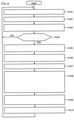
- FIG. 2 is a flow diagram for explaining resetting of the battery usage conditions.
- Embodiment 1 The operation of Embodiment 1 will be described in accordance with the step numbers illustrated in the drawing.
- Step S101 The battery information acquisition unit 221 acquires electrical characteristics (a current value I, a voltage value V, a temperature T) from a current sensor, a voltage sensor, a temperature sensor, or the like attached to or nearby the secondary battery 200a, and outputs the acquired electrical characteristics to the history storage unit 223.
- the history storage unit 223 makes a set of information such as "electrical characteristics,” “time information,” “past battery usage conditions” and the like, and stores it in history as battery information. That is, in Step S101, the battery information is periodically acquired and stored in history.
- Step S102 The lifespan prediction unit 224 maintains a battery deterioration database therein.
- the lifespan prediction unit 224 determines a degree of deterioration of the secondary battery 200a by checking the history of the battery information stored in the history storage unit 223 against the battery deterioration database. That is, in Step S102, the degree of degradation is determined from the (history of the) battery information.
- Step S103 The lifespan prediction unit 224 stores the progress of the degree of deterioration (the degree of deterioration information) as history in the history storage unit 223 together with the time information. That is, in Step 103, the degree of deterioration is stored.
- Step S104 The estimation unit 220 determines whether or not it is the reset timing of the battery usage condition based on the degree of deterioration of the battery and a predetermined time period.
- the estimation unit 220 In the case that it is not the reset timing of the battery usage condition, the estimation unit 220 returns to the operation of Step S101. On the other hand, in the case that it is determined that it is the reset timing of the battery usage condition, the estimation unit 220 shifts to the operation of Step S105.
- the reset timing may be determined at regular intervals, at unequal time intervals determined in advance, or at irregular intervals. In addition, the reset timing may be determined each time the degree of deterioration progresses by a fixed amount or a predetermined amount.
- Step S105 The lifespan prediction unit 224 predicts the estimated lifespan based on the progress of the degree of deterioration according to the present battery usage conditions.
- FIG. 3 is a diagram for explaining an example of an estimated lifespan prediction process.
- the horizontal axis in the figure indicates the number of years of usage, and the vertical axis indicates a performance index. It should be noted that the upper limit of the vertical axis is the initial performance of the secondary battery 200a and corresponds to a degree of degradation of zero, and the lower limit of the vertical axis is the performance lower limit value of the secondary battery 200a and corresponds to the upper limit of the degree of degradation.
- the actual deterioration curve indicated by the solid line is the deterioration curve under the present battery usage conditions stored in the history storage unit 223 in Step S103.
- the deterioration curve (prediction) indicated by the dotted line predicts the progress of the secondary battery 200a from the present onward.
- the number of years of usage when this deterioration curve (prediction) reaches the upper limit of the degree of deterioration (the performance lower limit value in FIG. 3 ) is the estimated lifespan.
- Step S106 The lifespan insufficiency calculation unit 232 obtains the lifespan insufficiency by subtracting the estimated lifespan from the target lifespan. That is, in Step S106, the (predicted) lifespan insufficiency that falls below the target lifespan is obtained based on the estimated lifespan.
- Step S107 The restriction setting unit 233 determines the reduction amount (that is, the extension amount of the battery lifespan) of the lifespan insufficiency to the next time.
- the reduction in the lifespan insufficiency may be distributed in a well-balanced manner during the period from the present to the target lifespan, thereby gradually extending the battery lifespan.
- a predetermined ratio for example, 10% to 90%, preferably 25% to 75%, more preferably 40% to 60%
- the predetermined ratio may be changed to nearly 100%, thereby substantially matching the battery lifespan with the target lifespan.
- Step S108 The restriction setting unit 233 restricts the present battery usage conditions so as to realize the lifespan extension of the lifespan insufficiency to the next time.
- the battery usage condition to be restricted at least one or a combination of two or more of the following is selected.
- Such a restriction of the battery usage conditions can be appropriately set by trying a change of the deterioration curve (prediction) in advance with a simulator or a deterioration acceleration experiment of the secondary battery 200a.
- Step S109 There are a plurality of candidates for the restricted battery usage conditions. Depending on which of these candidates is selected, the usage efficiency of the secondary battery 200a and the resulting deterioration in fuel consumption of the fuel engine 300a change. Accordingly, the restriction setting unit 233 selects, from among the candidates, a candidate for minimizing (that is, optimizing) the deterioration of the fuel consumption plan of the fuel engine 300a as the restricted battery usage condition. This selection operation is performed based on rules created by a simulation of the fuel consumption carried out in advance by the designer or the like.
- Step S110 The restriction setting unit 233 resets the restricted battery usage conditions with respect to the battery control unit 210 as the battery usage conditions until the next reset timing.
- Step S110 illustrated in FIG. 2
- Step S101 the resetting for restricting the battery usage conditions is repeated in a stepwise fashion.
- FIG. 4 is a diagram for explaining extension of a battery lifespan.
- the time period from the start of use to the target lifespan is divided into a plurality of time periods, and the reset timings of the battery usage conditions (the white circles in FIG. 4 ) are provided. For each reset timing, the lifespan insufficiency is estimated, and the battery usage conditions are reset to extend the battery lifespan.
- [A] in FIG. 5 is a diagram that illustrates lifespan insufficiency on the horizontal axis and an upper limit temperature on the vertical axis.
- the battery control unit 210 resets the battery usage conditions such that the larger the lifespan insufficiency, the lower the upper limit temperature of the battery. That is, [A] in the figure illustrates an example of resetting the upper limit temperature due to the lifespan insufficiency.
- [B] in FIG. 5 is a diagram that illustrates (upper limit temperature-present temperature) on the horizontal axis and the current amount of the battery on the vertical axis.
- the battery control unit 210 suppresses the amount of heat generated by the secondary battery 200a by reducing the amount of charge/discharge current of the secondary battery 200a such that the present temperature does not exceed the upper limit temperature. That is, [B] in FIG. 5 illustrates an example of current control to prevent exceeding the upper limit temperature.
- the upper limit temperature of the secondary battery 200a can be constrained.
- Embodiment 2 an operation of performing mutual compensation between train formation vehicles for a current insufficiency due to the constraint of the battery usage conditions will be described as Embodiment 2.
- FIG. 6 is a diagram for explaining the configuration of a train formation.
- a plurality of connected vehicles 10 are connected in a row in front of and behind the railroad vehicle 100 via a mechanical coupler or the like.
- Each of the connected vehicles 10 is provided with a battery system 200 (the battery control unit 210, the secondary battery 200a, and the like) and a vehicle engine 300 similar to those of the railroad vehicle 100.
- control system C and the power system E are connected between these vehicles via an electric coupler or a jumper coupler attached to the mechanical coupler.
- FIG. 7 is a flow diagram for explaining an accommodation operation for current insufficiency.
- the battery control unit 210 acquires the upper limit value of the discharge current that can be output from the secondary battery 200a based on the constraints of the present battery usage conditions.
- the battery control unit 210 of the railroad vehicle 100 estimates the amount of discharge current required for the secondary battery 200a in accordance with the operating state of the railroad vehicle, such as the acceleration or deceleration of the vehicle speed.
- Step S203 The battery control unit 210 of the railroad vehicle 100 compares the required value of the discharge current determined in S201 with the upper limit value determined in Step S202. In the case that a discharge current greater than the upper limit value is required, the battery control unit 210 determines that the discharge current is insufficient in the railroad vehicle 100, and shifts the operation to Step S204. On the other hand, in the case that the battery control unit 210 determines that a discharge current less than the upper limit value is sufficient, the railroad vehicle 100 determines that the discharge current has a surplus, and shifts the operation to Step S206. That is, in Step S203, in the case that "required discharge current > upper limit value" is YES, the process proceeds to S204, and if NO, the process proceeds to S206.
- Step S204 The battery control unit 210 of the railroad vehicle 100 communicates, via the control system C, to another group of connected vehicles 10 that the discharge current is insufficient in the railroad vehicle 100 alone.
- a connected vehicle 10 that has a secondary battery 200a with a surplus of discharge current distributes the surplus of discharge current to the electric power system E. That is, in Step S204, the current insufficiency is communicated to another connected vehicle.
- Step S205 The battery control unit 210 of the railroad vehicle 100 receives, via the electric power system E, the supply of the discharge current from the secondary battery 200a of the other connected vehicle 10 having a surplus of discharge current, and compensates for the insufficiency of the discharge current. After this operation, the battery control unit 210 of the railroad vehicle 100 returns to Step S201 and repeats the operation.
- Step S206 When the battery control unit 210 of the railroad vehicle 100 receives communication of the current insufficiency from another connected vehicle 10 via the control system C in a situation where there is a surplus of discharge current, it distributes the surplus of the discharge current to the other connected vehicle 10 via the power system E. After this operation, the battery control unit 210 of the railroad vehicle 100 returns to Step S201 and repeats the operation.
- Embodiment 2 By means of the series of operations described above, in Embodiment 2, the following effects can be obtained in addition to the effects of Embodiment 1.
- the present invention may be applied to a railroad vehicle that operates by power supply and battery power in an operation section that receives power from an overhead wire or a power supply rail or the like, and operates only by battery power in an operation section that does not have a power supply means.
- the battery system 200 monitors the status of the secondary battery 200a, resets the battery usage conditions, controls the charge/discharge and temperature of the secondary battery 200a, and accommodates the current insufficiency, but the present invention is not limited to this. For example, some or all of these functions may be shared by the control device of the railroad vehicle 100.
- Embodiment 2 of the embodiments accommodation of the current insufficiency is performed between vehicles, but the present invention is not limited thereto.
- a plurality of secondary batteries 200a having different replacement timings may be mounted in the railroad vehicle 100, and the battery control unit 210 may accommodate the current insufficiency between the plurality of secondary batteries 200a.
Landscapes
- Engineering & Computer Science (AREA)
- Manufacturing & Machinery (AREA)
- Chemical & Material Sciences (AREA)
- Chemical Kinetics & Catalysis (AREA)
- Electrochemistry (AREA)
- General Chemical & Material Sciences (AREA)
- Power Engineering (AREA)
- Life Sciences & Earth Sciences (AREA)
- Sustainable Development (AREA)
- Sustainable Energy (AREA)
- Transportation (AREA)
- Mechanical Engineering (AREA)
- Microelectronics & Electronic Packaging (AREA)
- Charge And Discharge Circuits For Batteries Or The Like (AREA)
- Secondary Cells (AREA)
- Electric Propulsion And Braking For Vehicles (AREA)
Abstract
Description
- The present invention relates to a battery system, a railroad vehicle, and a battery management method.
- Environmentally friendly hybrid railroad vehicles have been developed that achieve low fuel consumption, low exhaust emissions, and low noise by using an engine generator and a secondary battery in a complementary manner.
- Generally, this type of secondary battery deteriorates rapidly depending on the usage environment, such as charging/discharging and temperature, and the lifespan of these secondary batteries tends to be shortened.
- Accordingly, in order to reliably achieve the battery lifespan required in the design of secondary batteries, measures such as installing extra secondary batteries, or restricting the usage environment of the secondary batteries in advance to delay deterioration have been taken.
- For example,
Patent Document 1 discloses a control technique for restricting a current in order to delay deterioration when the lifespan of a secondary battery is short. - [Patent Document 1]
Japanese Unexamined Patent Application Publication No. 2016-163532 - In the hybrid railroad vehicle described above, in consideration of maintainability, replacement of the secondary battery is performed together with the replacement of other electronic parts. However, in the case that the battery system is designed such that the battery lifespan of the secondary battery is close to the assumption at the time of design, the battery lifespan may be reached before a target period (hereinafter referred to as a "target lifespan").
- Accordingly, it is an object of the present invention to provide a technique for bringing the battery lifespan closer to the target lifespan.
- In order to solve the above problems, a representative battery system of the present invention includes a battery control unit that controls a lifespan of the battery by constraining a battery usage condition associated with battery lifespan deterioration; an estimation unit that calculates an estimated lifespan of the battery obtained by constraining the battery usage condition; and a restriction unit that, in a case that the calculated estimated lifespan is less than a target lifespan of the battery, restricts and resets the battery usage condition of the battery control unit in order to extend a lifespan of the battery and reduce an insufficiency amount (hereinafter referred to as a "lifespan insufficiency") of the target lifespan.
- According to the present invention, it is possible to bring a battery lifespan closer to a target lifespan.
- Problems, configurations and effects other than those described above will be made clear by the following description of the embodiments.
-
- [
Figure 1] FIG. 1 is a diagram illustrating a configuration of arailroad vehicle 100. - [
Figure 2] FIG. 2 is a flow diagram for explaining resetting of a battery usage condition. - [
Figure 3] FIG. 3 is a diagram for explaining an example of an estimated lifespan prediction process. - [
Figure 4] FIG. 4 is a diagram for explaining extension of a battery lifespan. - [
Figure 5] FIG. 5 is a diagram for explaining an example of temperature control. - [
Figure 6] FIG. 6 is a diagram for explaining a configuration of a train formation. - [
Figure 7] FIG. 7 is a flow diagram for explaining an accommodation operation for current insufficiency. - Hereinafter, embodiments of the present invention will be described with reference to the drawings.
-
FIG. 1 is a diagram illustrating a configuration of arailroad vehicle 100. - In the figure, the
railroad vehicle 100 is configured to include abattery system 200 and avehicle engine 300. - The
battery system 200 is configured to incorporate asecondary battery 200a (for example, a lithium ion secondary battery cell), abattery control unit 210, anestimation unit 220, and arestriction unit 230 in an integrally replaceablebattery replacement package 200b. - For example, the functions of the
battery control unit 210, theestimation unit 220, and therestriction unit 230 may be realized by operating a processing device (including a memory) such as an ASIC, FPGA or a CPU with software. - The
secondary battery 200a is a battery that can be used repeatedly by charging and discharging. Thesecondary battery 200a is provided with a mechanism for temperature management (a Peltier device, a heater, a cooling fan, air cooling, liquid cooling, or the like), and a current sensor, a voltage sensor, a temperature sensor, or the like for measuring electrical characteristics, as necessary. - The
battery control unit 210 is initially set so as to constrain battery usage conditions associated with battery lifespan deterioration of thesecondary battery 200a, such as charge/discharge control and the operating temperature, and control the lifespan of thesecondary battery 200a so as to extend the lifespan from the target lifespan. Hereinafter, "constraining" in the present disclosure refers to setting limits such as upper limits and lower limits for battery usage conditions associated with battery lifespan deterioration, and using the battery. - The
estimation unit 220 includes a batteryinformation acquisition unit 221 that acquires battery information such as electrical characteristics from thesecondary battery 200a, a timeinformation acquisition unit 222 that acquires time information related to the use of thesecondary battery 200a, ahistory storage unit 223 that stores battery information, time information, and a history of battery usage conditions, and alifespan prediction unit 224 that obtains an estimated lifespan of thesecondary battery 200a based on the history of thehistory storage unit 223. - The
restriction unit 230 includes a targetlifespan setting unit 231 in which a target lifespan is set as the replacement period of thebattery replacement package 200b, a lifespan insufficiency calculation,unit 232 that calculates a predicted lifespan insufficiency of thesecondary battery 200a based on the difference between an estimated lifespan and the target lifespan, and arestriction setting unit 233 that restricts and resets the battery usage condition of thebattery control unit 210 in order to reduce the lifespan insufficiency. - The
vehicle engine 300 includes afuel engine 300a (a diesel engine or the like) such as a diesel engine, agenerator 310 that generates three-phase electric power by the power of thefuel engine 300a, a main converter 330 (a converter/inverter), a railroad vehicle motor 350 that generates propulsive force for therailroad vehicle 100, and a power supply line 360 (a power supply for a door opening/closing device, an air conditioner, or the like) in therailroad vehicle 100. - The
main converter 330 has a converter function for converting the three-phase power generated by thegenerator 310 into DC power, a charging function for charging thesecondary battery 200a with the converted DC power via thebattery control unit 210, an inverter function for converting the DC power of thesecondary battery 200a into three-phase power via thebattery control unit 210, and a hybrid function for complementarily switching the supply sources of the various types of electric power supplied to the railroad vehicle motor 350 and thepower supply line 360 between thegenerator 310 and thesecondary battery 200a. -
FIG. 2 is a flow diagram for explaining resetting of the battery usage conditions. - The operation of
Embodiment 1 will be described in accordance with the step numbers illustrated in the drawing. - Step S101: The battery
information acquisition unit 221 acquires electrical characteristics (a current value I, a voltage value V, a temperature T) from a current sensor, a voltage sensor, a temperature sensor, or the like attached to or nearby thesecondary battery 200a, and outputs the acquired electrical characteristics to thehistory storage unit 223. Thehistory storage unit 223 makes a set of information such as "electrical characteristics," "time information," "past battery usage conditions" and the like, and stores it in history as battery information. That is, in Step S101, the battery information is periodically acquired and stored in history. - Step S102: The
lifespan prediction unit 224 maintains a battery deterioration database therein. Thelifespan prediction unit 224 determines a degree of deterioration of thesecondary battery 200a by checking the history of the battery information stored in thehistory storage unit 223 against the battery deterioration database. That is, in Step S102, the degree of degradation is determined from the (history of the) battery information. - Step S103: The
lifespan prediction unit 224 stores the progress of the degree of deterioration (the degree of deterioration information) as history in thehistory storage unit 223 together with the time information. That is, inStep 103, the degree of deterioration is stored. - Step S104: The
estimation unit 220 determines whether or not it is the reset timing of the battery usage condition based on the degree of deterioration of the battery and a predetermined time period. - In the case that it is not the reset timing of the battery usage condition, the
estimation unit 220 returns to the operation of Step S101. On the other hand, in the case that it is determined that it is the reset timing of the battery usage condition, theestimation unit 220 shifts to the operation of Step S105. - The reset timing may be determined at regular intervals, at unequal time intervals determined in advance, or at irregular intervals. In addition, the reset timing may be determined each time the degree of deterioration progresses by a fixed amount or a predetermined amount.
- Step S105: The
lifespan prediction unit 224 predicts the estimated lifespan based on the progress of the degree of deterioration according to the present battery usage conditions. -
FIG. 3 is a diagram for explaining an example of an estimated lifespan prediction process. - The horizontal axis in the figure indicates the number of years of usage, and the vertical axis indicates a performance index. It should be noted that the upper limit of the vertical axis is the initial performance of the
secondary battery 200a and corresponds to a degree of degradation of zero, and the lower limit of the vertical axis is the performance lower limit value of thesecondary battery 200a and corresponds to the upper limit of the degree of degradation. - In the figure, the actual deterioration curve indicated by the solid line is the deterioration curve under the present battery usage conditions stored in the
history storage unit 223 in Step S103. On the other hand, the deterioration curve (prediction) indicated by the dotted line predicts the progress of thesecondary battery 200a from the present onward. - In general, in lithium ion secondary batteries or the like, a "root law deterioration curve" in which the degree of deterioration is directly proportional to the (1/2) power of the battery usage time is experimentally known. Accordingly, by fitting the deterioration curve of this root law to the deterioration curve (the solid line) under the current battery usage conditions, the deterioration curve (prediction) from the present onward, as indicated by a dotted line, can be obtained.
- The number of years of usage when this deterioration curve (prediction) reaches the upper limit of the degree of deterioration (the performance lower limit value in
FIG. 3 ) is the estimated lifespan. - It should be noted that, since the root law is a general example of a deterioration characteristic, it is preferable to use a deterioration law obtained for the actual
secondary battery 200a. - Step S106: The lifespan
insufficiency calculation unit 232 obtains the lifespan insufficiency by subtracting the estimated lifespan from the target lifespan. That is, in Step S106, the (predicted) lifespan insufficiency that falls below the target lifespan is obtained based on the estimated lifespan. - Step S107: The
restriction setting unit 233 determines the reduction amount (that is, the extension amount of the battery lifespan) of the lifespan insufficiency to the next time. At this time, rather than reducing the predicted lifespan insufficiency to zero all at once, the reduction in the lifespan insufficiency may be distributed in a well-balanced manner during the period from the present to the target lifespan, thereby gradually extending the battery lifespan. For example, a predetermined ratio (for example, 10% to 90%, preferably 25% to 75%, more preferably 40% to 60%) of the lifespan insufficiency may be determined as the reduction amount (the extension amount of the battery lifespan) to the next time. In addition, in the final period until the target lifespan is reached, the predetermined ratio may be changed to nearly 100%, thereby substantially matching the battery lifespan with the target lifespan. - Step S108: The
restriction setting unit 233 restricts the present battery usage conditions so as to realize the lifespan extension of the lifespan insufficiency to the next time. As the battery usage condition to be restricted here, at least one or a combination of two or more of the following is selected. - Charge Voltage Constraint
- Discharge Current Constraint
- Charge Current Constraint
- Battery State of Charge (SOC) Constraint
- Battery Temperature Constraint
- Such a restriction of the battery usage conditions can be appropriately set by trying a change of the deterioration curve (prediction) in advance with a simulator or a deterioration acceleration experiment of the
secondary battery 200a. - Step S109: There are a plurality of candidates for the restricted battery usage conditions. Depending on which of these candidates is selected, the usage efficiency of the
secondary battery 200a and the resulting deterioration in fuel consumption of thefuel engine 300a change. Accordingly, therestriction setting unit 233 selects, from among the candidates, a candidate for minimizing (that is, optimizing) the deterioration of the fuel consumption plan of thefuel engine 300a as the restricted battery usage condition. This selection operation is performed based on rules created by a simulation of the fuel consumption carried out in advance by the designer or the like. - Step S110: The
restriction setting unit 233 resets the restricted battery usage conditions with respect to thebattery control unit 210 as the battery usage conditions until the next reset timing. - When the resetting of the battery-usage condition is completed, the operation returns from Step S110 illustrated in
FIG. 2 to Step S101. By means of this operation, the resetting for restricting the battery usage conditions is repeated in a stepwise fashion. -
FIG. 4 is a diagram for explaining extension of a battery lifespan. - In the figure, the time period from the start of use to the target lifespan is divided into a plurality of time periods, and the reset timings of the battery usage conditions (the white circles in
FIG. 4 ) are provided. For each reset timing, the lifespan insufficiency is estimated, and the battery usage conditions are reset to extend the battery lifespan. - These operations continue until the target lifespan (the replacement period) is reached and the
battery replacement package 200b is replaced. - Next, an operation to constrain the upper limit temperature of the
secondary battery 200a in a case that thesecondary battery 200a does not have a cooling mechanism (a Peltier device, a cooling fan, liquid cooling, or the like) will be described. - [A] in
FIG. 5 is a diagram that illustrates lifespan insufficiency on the horizontal axis and an upper limit temperature on the vertical axis. - As illustrated in [A] in
FIG. 5 , thebattery control unit 210 resets the battery usage conditions such that the larger the lifespan insufficiency, the lower the upper limit temperature of the battery. That is, [A] in the figure illustrates an example of resetting the upper limit temperature due to the lifespan insufficiency. - [B] in
FIG. 5 is a diagram that illustrates (upper limit temperature-present temperature) on the horizontal axis and the current amount of the battery on the vertical axis. - When the present temperature of the
secondary battery 200a approaches the upper limit temperature, as illustrated in [B] ofFIG. 5 , thebattery control unit 210 suppresses the amount of heat generated by thesecondary battery 200a by reducing the amount of charge/discharge current of thesecondary battery 200a such that the present temperature does not exceed the upper limit temperature. That is, [B] inFIG. 5 illustrates an example of current control to prevent exceeding the upper limit temperature. - By means of such an operation of the
battery control unit 210, the upper limit temperature of thesecondary battery 200a can be constrained. - Hereinafter, the effects of
Embodiment 1 will be described. -
- (1) In
Embodiment 1, the battery usage conditions of thebattery control unit 210 are reset so as to extend the battery lifespan of thesecondary battery 200a. By resetting the battery usage conditions, the lifespan of thesecondary battery 200a can be extended to a target lifespan. - (2) In
Embodiment 1, as a battery usage condition, the charging voltage was restricted as an example. By reducing the upper limit of the charging voltage to delay the deterioration of thesecondary battery 200a, the battery lifespan is extended to the target lifespan. Alternatively, by increasing the lower limit of the charging voltage to delay the deterioration of thesecondary battery 200a, the battery lifespan is extended to the target lifespan. - (3) In
Embodiment 1, as a battery usage condition, the discharge current was restricted as an example. By restricting the discharge current to delay the deterioration of thesecondary battery 200a, the battery lifespan is extended to the target lifespan. - (4) In
Embodiment 1, as a battery usage condition, the charge current was restricted as an example. By limiting the charge current to delay the deterioration of thesecondary battery 200a, the battery lifespan is extended to the target lifespan. - (5) In
Embodiment 1, as a battery usage condition, a State of Charge condition (SOC) was restricted as an example. By reducing the battery SOC to delay the deterioration of thesecondary battery 200a, the battery lifespan is extended to the target lifespan. - (6) In
Embodiment 1, as a battery usage condition, the battery temperature was restricted as an example. By restricting the battery temperature to delay the deterioration of thesecondary battery 200a, the battery lifespan is extended to the target lifespan. - (7) In
Embodiment 1, in the case that there are a plurality of candidates or combinations thereof for the battery usage condition to be restricted, the one that minimizes the deterioration of the fuel consumption of thefuel engine 300a is selected. This selection action makes it possible to minimize fuel consumption deterioration. - (8) In
Embodiment 1, the estimated lifespan in the case that the present battery usage conditions are used is obtained by the same arithmetic processing as applying the predicted deterioration curve (the solid curve inFIG. 3 andFIG. 4 ) of thesecondary battery 200a to the actual deterioration curve (the solid curve inFIG. 3 andFIG. 4 ) using the present battery usage conditions.
In general, the calculation of the estimated lifespan is complicated because other deterioration factors (for example, the speed and distance traveled by therailroad vehicle 100, the weight load of therailroad vehicle 100, the difference in speed changes such as between limited express trains and local trains, and the like) are involved in the calculation of the estimated lifespan. However, by applying the predicted deterioration curve to an actual deterioration curve (the solid curve inFIG. 3 andFIG. 4 ) that reflects these deterioration factors, it becomes possible to easily and accurately calculate the estimated lifespan. - (9) In
Embodiment 1, as illustrated inFIG. 4 , the resetting of the battery usage conditions is performed gradually. The estimation accuracy of the battery lifespan becomes more accurate as the history of the battery information is accumulated. Accordingly, by repeating the estimation of the battery lifespan and the resetting of the battery usage conditions gradually as the target lifespan is approached, it becomes possible to make the battery lifespan closely coincide with the target lifespan. - (10) In
Embodiment 1, since the battery usage conditions are reset gradually, the battery usage conditions are reset from a relatively early stage. Accordingly, it is possible to gradually start extending the battery lifespan from a stage in which the battery performance is relatively sufficient, and it is possible to prevent a situation in which the battery lifespan is insufficient to reach the target lifespan in the final stages. - (11) In
Embodiment 1, as described above, the battery lifespan substantially coincides with the target lifespan (that is, the replacement period of thebattery replacement package 200b). Accordingly, by replacing thebattery replacement package 200b, it becomes possible to replace thesecondary battery 200a, thebattery control unit 210, theestimation unit 220, and therestriction unit 230 together, thereby improving the maintainability of battery replacement in therailroad vehicle 100. - Next, an operation of performing mutual compensation between train formation vehicles for a current insufficiency due to the constraint of the battery usage conditions will be described as Embodiment 2.
-
FIG. 6 is a diagram for explaining the configuration of a train formation. - It should be noted that, in
FIG. 6 , the same reference numerals are assigned to the same components as those ofEmbodiment 1, and a repetitive description thereof is omitted. - As a train formation, a plurality of connected vehicles 10 are connected in a row in front of and behind the
railroad vehicle 100 via a mechanical coupler or the like. - Each of the connected vehicles 10 is provided with a battery system 200 (the
battery control unit 210, thesecondary battery 200a, and the like) and avehicle engine 300 similar to those of therailroad vehicle 100. - Since the
battery system 200 of these vehicles is replaced at different times, the constraints on the battery usage conditions also differ from vehicle to vehicle. - The control system C and the power system E are connected between these vehicles via an electric coupler or a jumper coupler attached to the mechanical coupler.
-
FIG. 7 is a flow diagram for explaining an accommodation operation for current insufficiency. - Hereinafter, the operation will be described in accordance with the step numbers illustrated in
FIG. 7 . - S201: The
battery control unit 210 acquires the upper limit value of the discharge current that can be output from thesecondary battery 200a based on the constraints of the present battery usage conditions. - S202: The
battery control unit 210 of therailroad vehicle 100 estimates the amount of discharge current required for thesecondary battery 200a in accordance with the operating state of the railroad vehicle, such as the acceleration or deceleration of the vehicle speed. - Step S203: The
battery control unit 210 of therailroad vehicle 100 compares the required value of the discharge current determined in S201 with the upper limit value determined in Step S202. In the case that a discharge current greater than the upper limit value is required, thebattery control unit 210 determines that the discharge current is insufficient in therailroad vehicle 100, and shifts the operation to Step S204. On the other hand, in the case that thebattery control unit 210 determines that a discharge current less than the upper limit value is sufficient, therailroad vehicle 100 determines that the discharge current has a surplus, and shifts the operation to Step S206. That is, in Step S203, in the case that "required discharge current > upper limit value" is YES, the process proceeds to S204, and if NO, the process proceeds to S206. - Step S204: The
battery control unit 210 of therailroad vehicle 100 communicates, via the control system C, to another group of connected vehicles 10 that the discharge current is insufficient in therailroad vehicle 100 alone. Among the other connected vehicles 10, a connected vehicle 10 that has asecondary battery 200a with a surplus of discharge current distributes the surplus of discharge current to the electric power system E. That is, in Step S204, the current insufficiency is communicated to another connected vehicle. - Step S205: The
battery control unit 210 of therailroad vehicle 100 receives, via the electric power system E, the supply of the discharge current from thesecondary battery 200a of the other connected vehicle 10 having a surplus of discharge current, and compensates for the insufficiency of the discharge current. After this operation, thebattery control unit 210 of therailroad vehicle 100 returns to Step S201 and repeats the operation. - Step S206: When the
battery control unit 210 of therailroad vehicle 100 receives communication of the current insufficiency from another connected vehicle 10 via the control system C in a situation where there is a surplus of discharge current, it distributes the surplus of the discharge current to the other connected vehicle 10 via the power system E. After this operation, thebattery control unit 210 of therailroad vehicle 100 returns to Step S201 and repeats the operation. - By means of the series of operations described above, in Embodiment 2, the following effects can be obtained in addition to the effects of
Embodiment 1. -
- (1) In Embodiment 2, the discharge current of the
secondary battery 200a, which is insufficient due to the constraints of the battery usage conditions, can be compensated for by receiving a supply from the battery of another connected vehicle 10 having a surplus of current. - (2) In Embodiment 2, even if the discharge current is insufficient, since it can be compensated for from another connected vehicle 10, it is no longer necessary to frequently perform temporary power generation using the
fuel engine 300a, and the fuel consumption amount can be reduced. - (3) The resetting of the battery usage conditions for each vehicle described in
Embodiment 1 and the temporary accommodation of the discharge current between the vehicles described in Embodiment 2 are performed at the same time. Accordingly, a well-balanced battery management that eliminates the current insufficiency for each vehicle in the entire train formation while managing the lifespan of thesecondary battery 200a for each vehicle is realized. - It should be noted that, in the embodiments described above, application to a hybrid railroad vehicle equipped with a
fuel engine 300a has been described. However, the field of application of the present invention is not limited thereto. - For example, the present invention may be applied to a railroad vehicle that operates by power supply and battery power in an operation section that receives power from an overhead wire or a power supply rail or the like, and operates only by battery power in an operation section that does not have a power supply means.
- It should be noted that, in the embodiments, the
battery system 200 monitors the status of thesecondary battery 200a, resets the battery usage conditions, controls the charge/discharge and temperature of thesecondary battery 200a, and accommodates the current insufficiency, but the present invention is not limited to this. For example, some or all of these functions may be shared by the control device of therailroad vehicle 100. - In addition, in Embodiment 2 of the embodiments, accommodation of the current insufficiency is performed between vehicles, but the present invention is not limited thereto. For example, a plurality of
secondary batteries 200a having different replacement timings may be mounted in therailroad vehicle 100, and thebattery control unit 210 may accommodate the current insufficiency between the plurality ofsecondary batteries 200a. - As described above, various embodiments have been described, but the present invention is not limited to this content. Other aspects conceivable within the scope of the technical idea of the present invention are also included within the scope of the present invention. For example, the above-described examples have been described in detail in order to explain the present invention in an easy-to-understand manner, and are not necessarily limited to those comprising all the described configurations.
- It is also possible to replace a part of the configuration of one embodiment with the configuration of another embodiment, and it is also possible to add the configuration of one embodiment to the configuration of another embodiment.
- Further, it is possible to add, delete, or replace a part of the configuration of each embodiment.
- C... Control system, E... Power system, 10... Connected vehicle, 100... Railroad vehicle, 200... Battery system, 200a... Secondary battery, 200b... Battery replacement package, 210... Battery control unit, 220... Estimation unit, 221... Battery information acquisition unit, 222... Time information acquisition unit, 223... History storage unit, 224... Lifespan prediction unit, 230... Restriction unit, 231... Target lifespan setting unit, 232 ... Lifespan insufficiency calculation unit, 233... Restriction setting unit, 300... Vehicle engine, 300a... Fuel engine, 310... Generator, 330... Main converter, 350... Railroad vehicle motor, 360... Power supply line
Claims (11)
- A battery system having a repeatedly usable battery, the battery system comprising:a battery control unit that controls a lifespan of the battery by constraining a battery usage condition associated with battery lifespan deterioration;an estimation unit that calculates an estimated lifespan of the battery obtained by constraining the battery usage condition; anda restriction unit that, in a case that the calculated estimated lifespan is less than a target lifespan of the battery, restricts and resets the battery usage condition of the battery control unit in order to extend a lifespan of the battery and reduce an insufficiency amount (hereinafter referred to as a "lifespan insufficiency") of the target lifespan.
- The battery system according to claim 1, wherein:
the battery control unit compensates for a current amount insufficiency by receiving, from another battery that has a surplus of current, supply of a current amount of the battery that is insufficient due to restriction of the battery usage condition. - The battery system according to claim 2, wherein:the battery is a railroad vehicle battery for use in a railroad vehicle; andthe battery control unit compensates for a current amount insufficiency by receiving, from a battery of another connected vehicle that has a surplus of current, supply of a current amount of the battery that is insufficient due to restriction of the battery usage condition.
- The battery system according to any one of claims 1 to 3, wherein:
the restriction unit gradually performs resetting to restrict the battery usage condition, and gradually eliminates the lifespan insufficiency of the battery. - The battery system according to any one of claims 1 to 4, wherein:
the battery usage condition for which resetting to restrict is performed in the restriction unit includes at least one from a group including: a charge voltage constraint, a discharge current constraint, a charge current constraint, a battery state of charge (SoC) constraint, and a battery temperature constraint. - The battery system according to any one of claims 1 to 5, wherein:the restriction unit determines, according to the lifespan insufficiency, a constraint on an upper limit temperature of the battery; andthe battery control unit monitors a present temperature of the battery, and controls a charging/discharging current of the battery according to a difference between the upper limit temperature and the present temperature.
- The battery system according to any one of claims 1 to 6, wherein:the battery control unit, the estimation unit, and the restriction unit are integrally configured with respect to the battery; andwhen replacing a lifespan of the battery, the battery system can be integrally replaced.
- A railroad vehicle comprising:the battery system according to any one of claims 1 to 7; anda vehicle unit that uses the battery of the battery system as at least one of its power supplies.
- A battery management method that uses repeatedly usable batteries, the battery management method comprising:a battery control step for controlling a lifespan of the battery by constraining a battery usage condition associated with battery lifespan deterioration;an estimation step for calculating an estimated lifespan of the battery obtained by constraining the battery usage condition; anda restriction step for restricting and resetting, in a case that the calculated estimated lifespan is less than a target lifespan of the battery, the battery usage condition of the battery control unit in order to extend a lifespan of the battery and reduce an insufficiency amount (hereinafter referred to as a "lifespan insufficiency") of the target lifespan.
- The battery management method according to claim 9, wherein:
the battery control step compensates for a current amount insufficiency by receiving, from another battery that has a surplus of current, supply of a current amount of the battery that is insufficient due to restriction of the battery usage condition. - The battery system according to claim 9 or 10, wherein:the battery is a railroad vehicle battery for use in a railroad vehicle; andthe battery control step compensates for a current amount insufficiency by receiving, from a battery of another connected vehicle that has a surplus of current, supply of a current amount of the battery that is insufficient due to restriction of the battery usage condition.
Applications Claiming Priority (2)
| Application Number | Priority Date | Filing Date | Title |
|---|---|---|---|
| JP2019076064A JP7254597B2 (en) | 2019-04-12 | 2019-04-12 | BATTERY SYSTEM, RAIL VEHICLE AND BATTERY MANAGEMENT METHOD |
| PCT/JP2020/015341 WO2020209200A1 (en) | 2019-04-12 | 2020-04-03 | Battery system, railroad vehicle, and battery management method |
Publications (2)
| Publication Number | Publication Date |
|---|---|
| EP3955409A1 true EP3955409A1 (en) | 2022-02-16 |
| EP3955409A4 EP3955409A4 (en) | 2023-01-25 |
Family
ID=72751538
Family Applications (1)
| Application Number | Title | Priority Date | Filing Date |
|---|---|---|---|
| EP20787625.1A Pending EP3955409A4 (en) | 2019-04-12 | 2020-04-03 | BATTERY SYSTEM, RAIL VEHICLE, AND BATTERY MANAGEMENT SYSTEM |
Country Status (3)
| Country | Link |
|---|---|
| EP (1) | EP3955409A4 (en) |
| JP (1) | JP7254597B2 (en) |
| WO (1) | WO2020209200A1 (en) |
Families Citing this family (7)
| Publication number | Priority date | Publication date | Assignee | Title |
|---|---|---|---|---|
| JP2023076346A (en) * | 2021-11-22 | 2023-06-01 | 株式会社デンソーテン | Power supply and prediction method |
| JP2024116747A (en) * | 2023-02-16 | 2024-08-28 | 日立グローバルライフソリューションズ株式会社 | Vacuum cleaner |
| JP7694605B2 (en) * | 2023-05-22 | 2025-06-18 | トヨタ自動車株式会社 | Heating system control device, vehicle equipped with same, and heat medium management method |
| JP2025125417A (en) * | 2024-02-15 | 2025-08-27 | エナジーウィズ株式会社 | Business management method, program, and business management system |
| CN121970228A (en) * | 2024-08-27 | 2026-05-01 | 日本汽车能源株式会社 | Battery control device and battery control method |
| KR102854433B1 (en) * | 2024-08-30 | 2025-09-03 | 주식회사 중앙첨단소재 | Wheel axis power generation and power management system for railway vehicles |
| JP2026058386A (en) * | 2024-09-25 | 2026-04-06 | 株式会社日立ハイテク | Method for predicting the degradation state of secondary batteries, and a battery information management system. |
Family Cites Families (13)
| Publication number | Priority date | Publication date | Assignee | Title |
|---|---|---|---|---|
| JP4572850B2 (en) | 2006-03-24 | 2010-11-04 | 株式会社日立製作所 | Power control device |
| DE102009023340A1 (en) | 2009-05-29 | 2011-02-03 | Daimler Ag | Method for operating electric vehicle drive unit by multiple batteries of vehicle, involves determining aging condition or construction type for each battery, and determining power requirement for operating vehicle drive unit |
| CN102388499B (en) | 2010-03-23 | 2014-06-18 | 日本电气株式会社 | Method for charging/discharging lithium-ion secondary battery, and charging/discharging system |
| JP5679738B2 (en) * | 2010-08-26 | 2015-03-04 | 株式会社日立製作所 | Battery control device and vehicle system equipped with this battery control device |
| US20130294479A1 (en) * | 2011-01-24 | 2013-11-07 | Toyota Jidosha Kabushiki Kaisha | Electric storage system |
| JP5272033B2 (en) | 2011-03-23 | 2013-08-28 | 三菱重工業株式会社 | Battery system |
| JP6044249B2 (en) * | 2012-10-09 | 2016-12-14 | 三菱自動車工業株式会社 | Power control device |
| JP6089554B2 (en) * | 2012-10-09 | 2017-03-08 | 三菱自動車工業株式会社 | Power control device |
| US9263912B2 (en) * | 2013-02-05 | 2016-02-16 | Dell Products, L.P. | Mitigating premature wear out of a rechargeable battery |
| US9331503B2 (en) * | 2014-03-06 | 2016-05-03 | Nissan North America, Inc. | Systems and methods of controlling battery deterioration by controlling battery state-of-health during power exchange |
| JP6422798B2 (en) | 2015-03-05 | 2018-11-14 | 日立オートモティブシステムズ株式会社 | Battery management device, battery system, and hybrid vehicle control system |
| JP6441188B2 (en) * | 2015-09-01 | 2018-12-19 | 日立オートモティブシステムズ株式会社 | Battery management device, battery system, and hybrid vehicle control system |
| EP3424771A1 (en) * | 2017-07-03 | 2019-01-09 | Ningbo Geely Automobile Research & Development Co. Ltd. | Method and electronic device for managing a power limit |
-
2019
- 2019-04-12 JP JP2019076064A patent/JP7254597B2/en active Active
-
2020
- 2020-04-03 WO PCT/JP2020/015341 patent/WO2020209200A1/en not_active Ceased
- 2020-04-03 EP EP20787625.1A patent/EP3955409A4/en active Pending
Also Published As
| Publication number | Publication date |
|---|---|
| EP3955409A4 (en) | 2023-01-25 |
| JP7254597B2 (en) | 2023-04-10 |
| JP2020174490A (en) | 2020-10-22 |
| WO2020209200A1 (en) | 2020-10-15 |
Similar Documents
| Publication | Publication Date | Title |
|---|---|---|
| EP3955409A1 (en) | Battery system, railroad vehicle, and battery management method | |
| EP3916884B1 (en) | Secondary battery module remaining life diagnosis method and remaining life diagnosis system | |
| JP5980457B1 (en) | Power supply apparatus, transport apparatus having the power supply apparatus, estimation method for estimating correlation information between charging rate of storage unit and open-circuit voltage, and program for estimating correlation information | |
| AU2009274296B2 (en) | Method and system for control of a vehicle energy storage device | |
| KR101936465B1 (en) | System and Method for charging Battery | |
| KR102385058B1 (en) | Vehicle propulsion system having an energy storage system and optimized method of controlling operation thereof | |
| KR101459464B1 (en) | Method and system for controlling power of fuel cell vehicle | |
| US9783185B2 (en) | Vehicle propulsion system having an energy storage system and optimized method of controlling operation thereof | |
| CN110014935B (en) | Method for charging a battery of an electric vehicle | |
| US20160052410A1 (en) | Vehicle propulsion system having an energy storage system and optimized method of controlling operation thereof | |
| CN101551444A (en) | Method for estimating remaining capacity of battery | |
| CN109466375A (en) | Distance increasing unit control method and equipment, computer readable storage medium, vehicle | |
| CN112441027B (en) | Vehicle and method for operating a vehicle | |
| EP4292865A1 (en) | A method for controlling a power assembly | |
| KR20180096756A (en) | Method of operating a vehicle, control unit for drive system and drive system | |
| US9132737B2 (en) | Electromotive force device | |
| JP6572823B2 (en) | Power system | |
| KR20220027308A (en) | A system and method for power split of hybrid electric vehicle | |
| KR102656116B1 (en) | Energy management system for hybrid electric tram driven by multi-set hybrid power source | |
| KR101558705B1 (en) | Apparatus and Method for controlling charge of battery | |
| EP4535590A1 (en) | Ev management system | |
| JP2020174489A (en) | Battery system, rail vehicle and battery management method | |
| EP3437914B1 (en) | Switching control device and switching control method | |
| CN119821146A (en) | Vehicle power supply method and device, vehicle and storage medium | |
| KR20100060155A (en) | System and method for generator control optimizing of a battery of a car |
Legal Events
| Date | Code | Title | Description |
|---|---|---|---|
| STAA | Information on the status of an ep patent application or granted ep patent |
Free format text: STATUS: THE INTERNATIONAL PUBLICATION HAS BEEN MADE |
|
| PUAI | Public reference made under article 153(3) epc to a published international application that has entered the european phase |
Free format text: ORIGINAL CODE: 0009012 |
|
| STAA | Information on the status of an ep patent application or granted ep patent |
Free format text: STATUS: REQUEST FOR EXAMINATION WAS MADE |
|
| 17P | Request for examination filed |
Effective date: 20211112 |
|
| AK | Designated contracting states |
Kind code of ref document: A1 Designated state(s): AL AT BE BG CH CY CZ DE DK EE ES FI FR GB GR HR HU IE IS IT LI LT LU LV MC MK MT NL NO PL PT RO RS SE SI SK SM TR |
|
| DAV | Request for validation of the european patent (deleted) | ||
| DAX | Request for extension of the european patent (deleted) | ||
| A4 | Supplementary search report drawn up and despatched |
Effective date: 20230103 |
|
| RIC1 | Information provided on ipc code assigned before grant |
Ipc: H01M 10/48 20060101ALI20221221BHEP Ipc: H01M 10/44 20060101ALI20221221BHEP Ipc: H01M 10/42 20060101ALI20221221BHEP Ipc: B60L 50/61 20190101ALI20221221BHEP Ipc: G01R 31/392 20190101ALI20221221BHEP Ipc: B60L 58/21 20190101ALI20221221BHEP Ipc: B60L 58/16 20190101ALI20221221BHEP Ipc: B60L 50/60 20190101ALI20221221BHEP Ipc: H02J 7/00 20060101AFI20221221BHEP |