EP3955373A1 - Battery cell having improved weldability and processing apparatus thereof - Google Patents
Battery cell having improved weldability and processing apparatus thereof Download PDFInfo
- Publication number
- EP3955373A1 EP3955373A1 EP20917141.2A EP20917141A EP3955373A1 EP 3955373 A1 EP3955373 A1 EP 3955373A1 EP 20917141 A EP20917141 A EP 20917141A EP 3955373 A1 EP3955373 A1 EP 3955373A1
- Authority
- EP
- European Patent Office
- Prior art keywords
- battery cell
- pair
- processing apparatus
- cutters
- electrode lead
- Prior art date
- Legal status (The legal status is an assumption and is not a legal conclusion. Google has not performed a legal analysis and makes no representation as to the accuracy of the status listed.)
- Pending
Links
Images




Classifications
-
- H—ELECTRICITY
- H01—ELECTRIC ELEMENTS
- H01M—PROCESSES OR MEANS, e.g. BATTERIES, FOR THE DIRECT CONVERSION OF CHEMICAL ENERGY INTO ELECTRICAL ENERGY
- H01M10/00—Secondary cells; Manufacture thereof
- H01M10/04—Construction or manufacture in general
- H01M10/0404—Machines for assembling batteries
-
- B—PERFORMING OPERATIONS; TRANSPORTING
- B21—MECHANICAL METAL-WORKING WITHOUT ESSENTIALLY REMOVING MATERIAL; PUNCHING METAL
- B21F—WORKING OR PROCESSING OF METAL WIRE
- B21F11/00—Cutting wire
-
- H—ELECTRICITY
- H01—ELECTRIC ELEMENTS
- H01M—PROCESSES OR MEANS, e.g. BATTERIES, FOR THE DIRECT CONVERSION OF CHEMICAL ENERGY INTO ELECTRICAL ENERGY
- H01M50/00—Constructional details or processes of manufacture of the non-active parts of electrochemical cells other than fuel cells, e.g. hybrid cells
- H01M50/50—Current conducting connections for cells or batteries
- H01M50/543—Terminals
- H01M50/552—Terminals characterised by their shape
- H01M50/553—Terminals adapted for prismatic, pouch or rectangular cells
- H01M50/557—Plate-shaped terminals
-
- H—ELECTRICITY
- H01—ELECTRIC ELEMENTS
- H01M—PROCESSES OR MEANS, e.g. BATTERIES, FOR THE DIRECT CONVERSION OF CHEMICAL ENERGY INTO ELECTRICAL ENERGY
- H01M50/00—Constructional details or processes of manufacture of the non-active parts of electrochemical cells other than fuel cells, e.g. hybrid cells
- H01M50/10—Primary casings; Jackets or wrappings
- H01M50/102—Primary casings; Jackets or wrappings characterised by their shape or physical structure
- H01M50/103—Primary casings; Jackets or wrappings characterised by their shape or physical structure prismatic or rectangular
-
- B—PERFORMING OPERATIONS; TRANSPORTING
- B21—MECHANICAL METAL-WORKING WITHOUT ESSENTIALLY REMOVING MATERIAL; PUNCHING METAL
- B21D—WORKING OR PROCESSING OF SHEET METAL OR METAL TUBES, RODS OR PROFILES WITHOUT ESSENTIALLY REMOVING MATERIAL; PUNCHING METAL
- B21D17/00—Forming single grooves in sheet metal or tubular or hollow articles
- B21D17/02—Forming single grooves in sheet metal or tubular or hollow articles by pressing
-
- B—PERFORMING OPERATIONS; TRANSPORTING
- B21—MECHANICAL METAL-WORKING WITHOUT ESSENTIALLY REMOVING MATERIAL; PUNCHING METAL
- B21D—WORKING OR PROCESSING OF SHEET METAL OR METAL TUBES, RODS OR PROFILES WITHOUT ESSENTIALLY REMOVING MATERIAL; PUNCHING METAL
- B21D22/00—Shaping without cutting, by stamping, spinning, or deep-drawing
- B21D22/02—Stamping using rigid devices or tools
- B21D22/04—Stamping using rigid devices or tools for dimpling
-
- B—PERFORMING OPERATIONS; TRANSPORTING
- B26—HAND CUTTING TOOLS; CUTTING; SEVERING
- B26D—CUTTING; DETAILS COMMON TO MACHINES FOR PERFORATING, PUNCHING, CUTTING-OUT, STAMPING-OUT OR SEVERING
- B26D1/00—Cutting through work characterised by the nature or movement of the cutting member or particular materials not otherwise provided for; Apparatus or machines therefor; Cutting members therefor
- B26D1/01—Cutting through work characterised by the nature or movement of the cutting member or particular materials not otherwise provided for; Apparatus or machines therefor; Cutting members therefor involving a cutting member which does not travel with the work
- B26D1/04—Cutting through work characterised by the nature or movement of the cutting member or particular materials not otherwise provided for; Apparatus or machines therefor; Cutting members therefor involving a cutting member which does not travel with the work having a linearly-movable cutting member
-
- B—PERFORMING OPERATIONS; TRANSPORTING
- B26—HAND CUTTING TOOLS; CUTTING; SEVERING
- B26D—CUTTING; DETAILS COMMON TO MACHINES FOR PERFORATING, PUNCHING, CUTTING-OUT, STAMPING-OUT OR SEVERING
- B26D1/00—Cutting through work characterised by the nature or movement of the cutting member or particular materials not otherwise provided for; Apparatus or machines therefor; Cutting members therefor
- B26D1/01—Cutting through work characterised by the nature or movement of the cutting member or particular materials not otherwise provided for; Apparatus or machines therefor; Cutting members therefor involving a cutting member which does not travel with the work
- B26D1/04—Cutting through work characterised by the nature or movement of the cutting member or particular materials not otherwise provided for; Apparatus or machines therefor; Cutting members therefor involving a cutting member which does not travel with the work having a linearly-movable cutting member
- B26D1/045—Cutting through work characterised by the nature or movement of the cutting member or particular materials not otherwise provided for; Apparatus or machines therefor; Cutting members therefor involving a cutting member which does not travel with the work having a linearly-movable cutting member for thin material, e.g. for sheets, strips or the like
-
- B—PERFORMING OPERATIONS; TRANSPORTING
- B26—HAND CUTTING TOOLS; CUTTING; SEVERING
- B26D—CUTTING; DETAILS COMMON TO MACHINES FOR PERFORATING, PUNCHING, CUTTING-OUT, STAMPING-OUT OR SEVERING
- B26D1/00—Cutting through work characterised by the nature or movement of the cutting member or particular materials not otherwise provided for; Apparatus or machines therefor; Cutting members therefor
- B26D1/01—Cutting through work characterised by the nature or movement of the cutting member or particular materials not otherwise provided for; Apparatus or machines therefor; Cutting members therefor involving a cutting member which does not travel with the work
- B26D1/04—Cutting through work characterised by the nature or movement of the cutting member or particular materials not otherwise provided for; Apparatus or machines therefor; Cutting members therefor involving a cutting member which does not travel with the work having a linearly-movable cutting member
- B26D1/06—Cutting through work characterised by the nature or movement of the cutting member or particular materials not otherwise provided for; Apparatus or machines therefor; Cutting members therefor involving a cutting member which does not travel with the work having a linearly-movable cutting member wherein the cutting member reciprocates
-
- B—PERFORMING OPERATIONS; TRANSPORTING
- B26—HAND CUTTING TOOLS; CUTTING; SEVERING
- B26D—CUTTING; DETAILS COMMON TO MACHINES FOR PERFORATING, PUNCHING, CUTTING-OUT, STAMPING-OUT OR SEVERING
- B26D7/00—Details of apparatus for cutting, cutting-out, stamping-out, punching, perforating, or severing by means other than cutting
- B26D7/01—Means for holding or positioning work
-
- H—ELECTRICITY
- H01—ELECTRIC ELEMENTS
- H01M—PROCESSES OR MEANS, e.g. BATTERIES, FOR THE DIRECT CONVERSION OF CHEMICAL ENERGY INTO ELECTRICAL ENERGY
- H01M10/00—Secondary cells; Manufacture thereof
- H01M10/05—Accumulators with non-aqueous electrolyte
- H01M10/052—Li-accumulators
-
- H—ELECTRICITY
- H01—ELECTRIC ELEMENTS
- H01M—PROCESSES OR MEANS, e.g. BATTERIES, FOR THE DIRECT CONVERSION OF CHEMICAL ENERGY INTO ELECTRICAL ENERGY
- H01M10/00—Secondary cells; Manufacture thereof
- H01M10/05—Accumulators with non-aqueous electrolyte
- H01M10/052—Li-accumulators
- H01M10/0525—Rocking-chair batteries, i.e. batteries with lithium insertion or intercalation in both electrodes; Lithium-ion batteries
-
- H—ELECTRICITY
- H01—ELECTRIC ELEMENTS
- H01M—PROCESSES OR MEANS, e.g. BATTERIES, FOR THE DIRECT CONVERSION OF CHEMICAL ENERGY INTO ELECTRICAL ENERGY
- H01M50/00—Constructional details or processes of manufacture of the non-active parts of electrochemical cells other than fuel cells, e.g. hybrid cells
- H01M50/10—Primary casings; Jackets or wrappings
- H01M50/102—Primary casings; Jackets or wrappings characterised by their shape or physical structure
- H01M50/105—Pouches or flexible bags
-
- H—ELECTRICITY
- H01—ELECTRIC ELEMENTS
- H01M—PROCESSES OR MEANS, e.g. BATTERIES, FOR THE DIRECT CONVERSION OF CHEMICAL ENERGY INTO ELECTRICAL ENERGY
- H01M50/00—Constructional details or processes of manufacture of the non-active parts of electrochemical cells other than fuel cells, e.g. hybrid cells
- H01M50/10—Primary casings; Jackets or wrappings
- H01M50/172—Arrangements of electric connectors penetrating the casing
- H01M50/174—Arrangements of electric connectors penetrating the casing adapted for the shape of the cells
- H01M50/176—Arrangements of electric connectors penetrating the casing adapted for the shape of the cells for prismatic or rectangular cells
-
- H—ELECTRICITY
- H01—ELECTRIC ELEMENTS
- H01M—PROCESSES OR MEANS, e.g. BATTERIES, FOR THE DIRECT CONVERSION OF CHEMICAL ENERGY INTO ELECTRICAL ENERGY
- H01M50/00—Constructional details or processes of manufacture of the non-active parts of electrochemical cells other than fuel cells, e.g. hybrid cells
- H01M50/50—Current conducting connections for cells or batteries
- H01M50/531—Electrode connections inside a battery casing
- H01M50/533—Electrode connections inside a battery casing characterised by the shape of the leads or tabs
-
- H—ELECTRICITY
- H01—ELECTRIC ELEMENTS
- H01M—PROCESSES OR MEANS, e.g. BATTERIES, FOR THE DIRECT CONVERSION OF CHEMICAL ENERGY INTO ELECTRICAL ENERGY
- H01M50/00—Constructional details or processes of manufacture of the non-active parts of electrochemical cells other than fuel cells, e.g. hybrid cells
- H01M50/50—Current conducting connections for cells or batteries
- H01M50/531—Electrode connections inside a battery casing
- H01M50/534—Electrode connections inside a battery casing characterised by the material of the leads or tabs
-
- H—ELECTRICITY
- H01—ELECTRIC ELEMENTS
- H01M—PROCESSES OR MEANS, e.g. BATTERIES, FOR THE DIRECT CONVERSION OF CHEMICAL ENERGY INTO ELECTRICAL ENERGY
- H01M50/00—Constructional details or processes of manufacture of the non-active parts of electrochemical cells other than fuel cells, e.g. hybrid cells
- H01M50/50—Current conducting connections for cells or batteries
- H01M50/543—Terminals
- H01M50/547—Terminals characterised by the disposition of the terminals on the cells
- H01M50/55—Terminals characterised by the disposition of the terminals on the cells on the same side of the cell
-
- H—ELECTRICITY
- H01—ELECTRIC ELEMENTS
- H01M—PROCESSES OR MEANS, e.g. BATTERIES, FOR THE DIRECT CONVERSION OF CHEMICAL ENERGY INTO ELECTRICAL ENERGY
- H01M50/00—Constructional details or processes of manufacture of the non-active parts of electrochemical cells other than fuel cells, e.g. hybrid cells
- H01M50/50—Current conducting connections for cells or batteries
- H01M50/543—Terminals
- H01M50/552—Terminals characterised by their shape
-
- H—ELECTRICITY
- H01—ELECTRIC ELEMENTS
- H01M—PROCESSES OR MEANS, e.g. BATTERIES, FOR THE DIRECT CONVERSION OF CHEMICAL ENERGY INTO ELECTRICAL ENERGY
- H01M50/00—Constructional details or processes of manufacture of the non-active parts of electrochemical cells other than fuel cells, e.g. hybrid cells
- H01M50/50—Current conducting connections for cells or batteries
- H01M50/543—Terminals
- H01M50/562—Terminals characterised by the material
-
- H—ELECTRICITY
- H01—ELECTRIC ELEMENTS
- H01M—PROCESSES OR MEANS, e.g. BATTERIES, FOR THE DIRECT CONVERSION OF CHEMICAL ENERGY INTO ELECTRICAL ENERGY
- H01M50/00—Constructional details or processes of manufacture of the non-active parts of electrochemical cells other than fuel cells, e.g. hybrid cells
- H01M50/50—Current conducting connections for cells or batteries
- H01M50/543—Terminals
- H01M50/564—Terminals characterised by their manufacturing process
-
- H—ELECTRICITY
- H01—ELECTRIC ELEMENTS
- H01M—PROCESSES OR MEANS, e.g. BATTERIES, FOR THE DIRECT CONVERSION OF CHEMICAL ENERGY INTO ELECTRICAL ENERGY
- H01M50/00—Constructional details or processes of manufacture of the non-active parts of electrochemical cells other than fuel cells, e.g. hybrid cells
- H01M50/50—Current conducting connections for cells or batteries
- H01M50/543—Terminals
- H01M50/564—Terminals characterised by their manufacturing process
- H01M50/566—Terminals characterised by their manufacturing process by welding, soldering or brazing
-
- Y—GENERAL TAGGING OF NEW TECHNOLOGICAL DEVELOPMENTS; GENERAL TAGGING OF CROSS-SECTIONAL TECHNOLOGIES SPANNING OVER SEVERAL SECTIONS OF THE IPC; TECHNICAL SUBJECTS COVERED BY FORMER USPC CROSS-REFERENCE ART COLLECTIONS [XRACs] AND DIGESTS
- Y02—TECHNOLOGIES OR APPLICATIONS FOR MITIGATION OR ADAPTATION AGAINST CLIMATE CHANGE
- Y02E—REDUCTION OF GREENHOUSE GAS [GHG] EMISSIONS, RELATED TO ENERGY GENERATION, TRANSMISSION OR DISTRIBUTION
- Y02E60/00—Enabling technologies; Technologies with a potential or indirect contribution to GHG emissions mitigation
- Y02E60/10—Energy storage using batteries
-
- Y—GENERAL TAGGING OF NEW TECHNOLOGICAL DEVELOPMENTS; GENERAL TAGGING OF CROSS-SECTIONAL TECHNOLOGIES SPANNING OVER SEVERAL SECTIONS OF THE IPC; TECHNICAL SUBJECTS COVERED BY FORMER USPC CROSS-REFERENCE ART COLLECTIONS [XRACs] AND DIGESTS
- Y02—TECHNOLOGIES OR APPLICATIONS FOR MITIGATION OR ADAPTATION AGAINST CLIMATE CHANGE
- Y02P—CLIMATE CHANGE MITIGATION TECHNOLOGIES IN THE PRODUCTION OR PROCESSING OF GOODS
- Y02P70/00—Climate change mitigation technologies in the production process for final industrial or consumer products
- Y02P70/50—Manufacturing or production processes characterised by the final manufactured product
Definitions
- the present invention relates to a battery cell with improved weldability and an apparatus for processing the same, and more particularly to a battery cell with improved weldability configured such that a negative electrode lead is provided with an embossed portion, whereby weld defects are minimized, and such that the embossed portion can be formed in the negative electrode lead simultaneously with cutting of leads, whereby the battery cell is easily processed, and an apparatus for processing the same.
- secondary batteries which are energy sources substituting for fossil fuels causing air pollution, have been applied to an electric vehicle (EV), a hybrid electric vehicle (HEV), and a plug-in hybrid electric vehicle (P-HEV), and therefore there is an increasing necessity for development of secondary batteries.
- EV electric vehicle
- HEV hybrid electric vehicle
- P-HEV plug-in hybrid electric vehicle
- the lithium secondary battery is in the spotlight, since the lithium secondary battery has little memory effect, whereby the lithium secondary battery is capable of being freely charged and discharged, has a very low self-discharge rate, and has high energy density, compared to the nickel-based secondary batteries.
- a separate metal plate is necessary in order to connect a plurality of battery cells to each other in series or in parallel. That is, a plurality of electrode leads is coupled to each other, or an electrode lead and a metal plate are coupled to each other, using a known joining method, such as welding. At this time, however, weld defects occur due to various causes, whereby manufacturing costs are increased.
- the conventional battery cell 10 includes an electrode assembly, a pair of electrode leads 12 welded to a plurality of electrode tabs 11 extending from the electrode assembly, and a case 13 configured to receive the electrode assembly.
- each of the electrode leads 12 has a simple flat shape, as described above, the electrode leads may not be properly brought into tight contact with an object to be welded, whereby there is a high possibility of occurrence of weld defects.
- a battery cell undergoes a process of cutting leads thereof so as to satisfy prescribed standards.
- the leads may be bent and thus may not be cut at predetermined positions thereof, or cutters configured to cut the leads must be frequently replaced.
- FIG. 2 is a side view of a conventional battery cell processing apparatus.
- the conventional processing apparatus is configured such that a seating jig 22 is located on the upper surface of a base 21 and such that a cutting body 23, a pneumatic member 24, a cutting member 25, and an upper cutting knife 26 are provided adjacent thereto.
- a cell case 11 is mounted on the seating jig 22 such that a lead 12 is exposed in the direction in which the cutting body 23 is located, the upper cutting knife 26 is moved downwards, and the lead is cut at the point at which a lower cutting knife 27 is located.
- the cut surface may not be vertical.
- the upper cutting knife and the lower cutting knife which form a pair of cutting knives, are provided, whereby the apparatus is complicated. Also, in the case in which the cutting knives become dull, both of the cutting knives must be replaced, whereby maintenance expenses are increased.
- Patent Document 1 Korean Patent Application Publication No. 2006-0011312
- the present invention has been made in view of the above problems, and it is an object of the present invention to provide a battery cell configured such that weld quality of the battery cell can be improved at the time of resistance welding.
- a battery cell according to the present invention is configured such that an electrode assembly is received in a cell case (110) and a pair of electrode leads constituted by a negative electrode lead (120) and a positive electrode lead (130) protrudes outwards from the cell case (110), wherein the negative electrode lead (120) is made of a nickel material and is provided with one or more embossed portions (121), and the positive electrode lead (130) is made of an aluminum material and is provided with no embossed portion.
- a battery cell processing apparatus includes a base portion (210) having a seating die (211), configured to support a cell case (110) and a pair of leads, provided on the upper surface thereof, a vertical fixing portion (220) fixed to a predetermined region of one side of the base portion (210) so as to be perpendicular to the base portion, a block portion (230) connected to the vertical fixing portion (220) so as to be movable upwards and downwards relative to the vertical fixing portion, a pair of cutters (250) located at the bottom surface of the block portion (230), the pair of cutters being configured to cut a negative electrode lead (120) and a positive electrode lead (130), the pair of cutters being spaced apart from each other by a predetermined distance, and a pair of support portions (270) located at the bottom surface of the block portion (230), the pair of support portions being located parallel to the pair of cutters (250) in a horizontal direction, wherein one of the pair of support portions (270) is provided on the bottom surface thereof with
- the battery cell processing apparatus may further include a second connection portion (260) configured to connect the block portion (230) and the pair of cutters (250) to each other and a third connection portion (280) configured to connect the block portion (230) and the pair of support portions (270) to each other, wherein the third connection portion (280) may be constituted by an elastic member capable of being expanded and contracted in a vertical direction, and the second connection portion (260) may not be capable of being expanded and contracted in the vertical direction.
- the third connection portion (280) may include a spring.
- the pair of cutters (250) may include a first cutter (251) and a second cutter (252), the pair of support portions (270) may include a first support portion (271) and a second support portion (272), and the first cutter (251) and the first support portion (271) may be located adjacent to each other while the second cutter (252) and the second support portion (272) may be located adjacent to each other.
- each of the cutters (250) may have a teragonal shape.
- each of the cutters (250) has a hexahedral shape.
- each of the cutters (250) may include a front portion (251(a)), a rear portion (251(b)), a bottom portion (251(c)) configured to connect lower parts of the front portion (251(a)) and the rear portion (251(b)) to each other, a pair of edge portions (251(d)) formed at the position at which the front portion (251(a)) and the bottom portion (251(c)) join each other and the position at which the rear portion (251(b)) and the bottom portion (251(c)) join each other, and a pair of side portions (251(e)) configured to connect side parts of the front portion (251(a)) and the rear portion (251(b)) to each other, and each of the pair of side portions (251(e)) may be further provided with an extension portion (251(f)) extending a predetermined length in a downward direction.
- each of the edge portions (251(d)) may form a right angle.
- one side surface of each of the cutters (250) may be moved along one side surface of the seating die (211) in the vertical direction, and each of the support portions (270) may be moved above the upper surface of the seating die (211) in the vertical direction.
- the distance between the one side surface of the seating die (211) and the one side surface of each of the cutters (250) may be greater than 0 mm to less than 0.05 mm.
- a battery cell processing method includes a first step of placing a battery cell to be processed on the upper surface of a seating die (211) of a base portion (210), a second step of moving the seating die (211) forwards, a third step of moving a block portion (230) downwards in the vertical direction to cut a negative electrode lead (120) and a positive electrode lead (130) to a predetermined length and at the same time to form one or more embossed portions (121) in the negative electrode lead (120), and a fourth step of separating the processed battery cell from the seating die (211), the steps being repeatedly performed, wherein, after a predetermined number of battery cells are processed, cutters (250) are rotated 180 degrees in a clockwise direction or in a counterclockwise direction, and the steps are repeatedly performed.
- a battery cell according to the present invention has an advantage in that a negative electrode lead of the battery cell is provided with one or more embossed portions, whereby weld quality of the battery cell is improved at the time of resistance welding with a metal plate.
- a battery cell processing apparatus has an advantage in that a cutter configured to cut a lead and a support portion configured to form an embossed portion and to support the lead are simultaneously moved upwards and downwards by driving of a block portion, whereby processing accuracy is high and processing time is reduced.
- the cutter according to the present invention has a tetragonal shape, whereby durability of the cutter is excellent, and a pair of opposite edges of the cutter can be used as the edges of a knife, which is economical.
- FIG. 3 is a perspective view of a battery cell according to a preferred embodiment of the present invention.
- the battery cell according to the present invention includes a cell case 110, an electrode assembly (not shown), and a pair of leads.
- the cell case 110 is generally configured to have a laminate sheet structure including an inner layer, a metal layer, and an outer layer.
- the inner layer is disposed in direct contact with the electrode assembly, and therefore the inner layer must exhibit high insulation properties and high resistance to an electrolytic solution.
- the inner layer must exhibit high sealability in order to hermetically seal the cell case from the outside, i.e. a thermally-bonded sealed portion between inner layers must exhibit excellent thermal bonding strength.
- the inner layer may be made of a material selected from among a polyolefin-based resin, such as polypropylene, polyethylene, polyethylene-acrylic acid, or polybutylene, a polyurethane resin, and a polyimide resin, which exhibit excellent chemical resistance and high sealability.
- polypropylene which exhibits excellent mechanical-physical properties, such as tensile strength, rigidity, surface hardness, and resistance to impact strength, and excellent chemical resistance, is the most preferably used.
- the metal layer which is disposed so as to abut the inner layer, corresponds to a barrier layer configured to prevent moisture or various kinds of gas from permeating into the battery from the outside.
- Aluminum foil which is light and easily formable, may be used as a preferred material for the metal layer.
- the outer layer is provided on the other surface of the metal layer.
- the outer layer may be made of a heat-resistant polymer that exhibits excellent tensile strength, resistance to moisture permeation, and resistance to air transmission such that the outer layer exhibits high heat resistance and chemical resistance while protecting the electrode assembly.
- the outer layer may be made of nylon or polyethylene terephthalate.
- the present invention is not limited thereto.
- the electrode assembly constituting the battery cell 100 may be a jelly-roll type electrode assembly, which is configured to have a structure in which a long sheet type positive electrode and a long sheet type negative electrode are wound in the state in which a separator is interposed between the positive electrode and the negative electrode, a stacked type electrode assembly including unit cells, each of which is configured to have a structure in which a rectangular positive electrode and a rectangular negative electrode are stacked in the state in which a separator is interposed therebetween, a stacked and folded type electrode assembly, which is configured to have a structure in which unit cells are wound using a long separation film, or a laminated and stacked type electrode assembly, which is configured to have a structure in which unit cells are stacked in the state in which a separator is interposed therebetween and are then attached to each other.
- the present invention is not limited thereto.
- the pair of electrode leads includes a negative electrode lead 120 and a positive electrode lead 130.
- the leads may be exposed out of the cell case 110 in the state in which a negative electrode tab and a positive electrode tab of the electrode assembly are electrically connected respectively to the leads.
- the negative electrode lead 120 and the positive electrode lead 130 may be directly connected to the electrode assembly without the negative electrode tab and the positive electrode tab.
- the negative electrode lead 120 be made of a nickel material and be provided with one or more embossed portions 121, more preferably two or more embossed portions. It is more preferable that the positive electrode lead 130 be made of an aluminum material and be formed in a flat shape having no embossed portion.
- the battery cell 100 must be joined to a metal plate, such as a nickel plate, for parallel connection or series connection.
- a metal plate such as a nickel plate
- welding defects due to weak-welding or non-welding may be minimized at the time of resistance welding.
- the positive electrode lead 130 since the melting point of the positive electrode lead 130 is lower than the melting point of nickel, the positive electrode lead may not be properly joined but may be ruptured at the time of resistance welding. At the time of resistance welding between the nickel plate and the aluminum positive electrode lead, therefore, it is advantageous that no embossed portion is formed in the positive electrode lead in order to secure sufficient contact area.
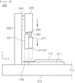
- FIG. 4 is a side view of a battery cell processing apparatus according to a preferred embodiment of the present invention
- FIG. 5 is a perspective view of the battery cell processing apparatus according to the preferred embodiment of the present invention.
- the battery cell processing apparatus 200 includes a base portion 210, a vertical fixing portion 220, a block portion 230, a first connection portion 240, a pair of cutters 250, a pair of second connection portions 260, a pair of support portions 270, and a pair of third connection portions 280.
- the base portion 210 may be configured to have the shape of an approximately quadrangular plate having a flat upper surface, and a seating die 211 located on the upper surface may be mounted so as to be slidable forwards or rearwards, which is an X-axis direction.
- a seating die 211 located on the upper surface may be mounted so as to be slidable forwards or rearwards, which is an X-axis direction.
- one side surface of the seating die 211, on which the negative electrode lead 120 is seated and from which the negative electrode lead protrudes be perpendicular to the negative electrode lead.
- the vertical fixing portion 220 located at one side of the base portion 210 is configured to hold the pair of cutters 250 and the pair of support portions 270 connected to the block portion 230 so as to be movable upwards and downwards in the state of being spaced apart from the seating die 211 by a predetermined distance. That is, the block portion 230 is movable upwards and downwards (in a Y-axis direction) through the intervention of the first connection portion 240, one side of which is connected to the vertical fixing portion 220 and the other side of which is connected to the block portion 230.
- the vertical fixing portion 220 be constituted by two pillars or a single pillar having a large width in order to secure stability thereof, although the vertical fixing portion is configured to have a single pillar shape having a small width.
- the block portion 230 which is supported by the vertical fixing portion 220 so as to be movable upwards and downwards, may have a predetermined shape, such as a hexahedral shape.
- the block portion 230 may be constituted by two parts. However, it is more preferable that a single block portion be provided in order to simultaneously move the pair of cutters 250 and the pair of support portions 270 upwards and downwards by one manipulation.
- the pair of cutters 250 and the pair of support portions 270 are located under the block portion 230.
- a first cutter 251 and a second cutter 252, which constitute the pair of cutters 250, are configured to cut the negative electrode lead 120 and the positive electrode lead 130 to a predetermined length, respectively.
- the pair of support portions 270 which includes a first support portion 271 and a second support portion 272, is configured to prevent the leads from being bent at the time of cutting, thereby minimizing product defects.
- the pair of support portions is configured to form the embossed portions 121 in the negative electrode lead 120 simultaneously with cutting.
- FIG. 6 is a perspective view of a cutter according to a preferred embodiment of the present invention
- FIG. 6(a) is a front perspective view and FIG. 6(b) is a rear perspective view
- FIG. 7 is a perspective view of support portions according to a preferred embodiment of the present invention
- FIG. 7(a) is a perspective view of a first support portion
- FIG. 7(b) is a perspective view of a second support portion
- the first cutter 251 and the second cutter 252 according to the present invention are identical in construction to each other. Consequently, only the first cutter 251 will be described in detail with reference to FIG. 6 .
- the first cutter 251 includes a front portion 251(a), a rear portion 251(b), a bottom portion 251(c), a pair of edge portions 251(d), and a pair of side portions 251(e).
- the bottom portion 251(c) connects lower parts of the front portion 251(a) and the rear portion 251(b) to each other, and the pair of edge portions 251(d), which is formed at the position at which the front portion 251(a) and the bottom portion 251(c) join each other and at the position at which the rear portion 251(b) and the bottom portion 251(c) join each other, serves as the edge of a knife configured to cut the lead.
- angles of the edge portions 251(d), i.e. the angle between the front portion 251(a) and the bottom portion 251(c) and the angle between the rear portion 251(b) and the bottom portion 251(c), be a right angle.
- This configuration is provided to cut each of the negative electrode lead 120 and the positive electrode lead 130 so as to have a vertical cut surface.
- Each of the pair of side portions 251 (e) may be further provided with an extension portion 251(f) extending a predetermined length in a downward direction.
- This configuration is provided to allow the cutter 251 to move along slit grooves formed in the seating die 211 at the time of upward and downward movement thereof to thus accurately guide sliding of the cutter 251 in a vertical direction without being twisted leftwards and rightwards.
- the first cutter 251 may have a teragonal shape with the extension portions 251(f) omitted, for example, a hexahedral shape.
- the support portions 270 include a first support portion 271 configured to support the negative electrode lead 120 and at the same time to form the embossed portions 121 and a second support portion 272 configured to support the positive electrode lead 130.
- the bottom surface of each of the support portions 270 is flat so as to support the upper surface of a corresponding one of the leads in the state of being in entirely tight contact therewith.
- the first support portion 271 is provided on the bottom surface thereof with protrusions 271a equal in number to embossed portions 121 to be formed.
- the cutters 250 and the support portions 270 having the constructions described above are disposed as follows.
- the support portions 270 are located at positions relatively close to the cell case 110, and the cutters 250 are located at positions relatively distant from the cell case.
- the support portions 270 and the cutters 250 are located so as to be adjacent to each other.
- first cutter 251 and the first support portion 271 constitute one assembly
- second cutter 252 and the second support portion 272 constitute another assembly.
- the distance between each of the support portions and a corresponding one of the cutters may be greater than 0 mm to less than 0.1 mm.
- the side surface of the support portion and/or the cutter may be worn by friction, and great driving force is necessary to move the support portion and the cutter upwards and downwards.
- the support portion and the cutter are disposed so as to be excessively spaced apart from each other, on the other hand, it is not possible to inhibit bending of the lead, whereby it is not possible to accurately cut the lead.
- the cutters 250 are connected to the block portion 230 via the second connection portions 260, and the support portions 270 are connected to the block portion 230 via the third connection portions 280.
- the first cutter 251 and the second cutter 252 are connected to a 2' connection portion 261 and a 2" connection portion 262, respectively, and the first support portion 271 and the second support portion 272 are connected to a 3' connection portion 281 and a 3" connection portion 282, respectively.
- each of the third connection portions 280 connected to the support portions 270 i.e. each of the 3' connection portion 281 and the 3" connection portion 282
- each of the 2' connection portion 261 and the 2" connection portion 262 connected to the cutters 250 is configured in the form of a bar having no length change.
- air cylinders may be further provided between the block portion 230 and the third connection portions 280 and/or between the third connection portions 280 and the support portions 270, although not shown in the figures.
- the reason for this is that, when the block 230 is moved downwards, as shown in FIG. 4 , the first support portion 271 must push the lead while being located on the upper surface of the lead, and the first cutter 251 must be moved downwards more than the first support portion 271 in order to cut the lead.
- the distance between the vertical surface of the seating die 211 and one side surface of the first cutter 251 that faces the vertical surface of the seating die 211 may be greater than 0 mm to less than 0.05 mm. This configuration is provided to prevent friction therebetween and to accurately cut the lead.
- the battery cell processing method includes a first step of placing a battery cell to be processed on the upper surface of the seating die 211 of the base portion 210, a second step of moving the seating die 211 forwards, a third step of moving the block portion 230 downwards in the vertical direction to cut a negative electrode lead 120 and a positive electrode lead 130 to a predetermined length and at the same time to form one or more embossed portions 121 in the negative electrode lead 120, and a fourth step of separating the processed battery cell from the seating die 211.
- the above steps are repeatedly performed.
- each of the cutters 250 which corresponds to the edge of a knife, becomes dull as the result of processing a predetermined number of battery cells
- the cutters 250 are separated from the block portion 230 and are then rotated 180 degrees clockwise or counterclockwise in order to cut leads using the other edges.
- the bottom portion 251(c) of each of the cutters 250 may be ground or cut by a predetermined thickness such that the front portion 251(a) and the bottom portion 251(c) form a right angle therebetween and the rear portion 251(b) and the bottom portion 251(c) form a right angle therebetween, whereby the cutters may be reused.
Landscapes
- Chemical & Material Sciences (AREA)
- Chemical Kinetics & Catalysis (AREA)
- Electrochemistry (AREA)
- General Chemical & Material Sciences (AREA)
- Engineering & Computer Science (AREA)
- Mechanical Engineering (AREA)
- Manufacturing & Machinery (AREA)
- Life Sciences & Earth Sciences (AREA)
- Forests & Forestry (AREA)
- Materials Engineering (AREA)
- Connection Of Batteries Or Terminals (AREA)
Abstract
Description
- This application claims the benefit of priority to
Korean Patent Application No. 2020-0010843 filed on January 30, 2020 - The present invention relates to a battery cell with improved weldability and an apparatus for processing the same, and more particularly to a battery cell with improved weldability configured such that a negative electrode lead is provided with an embossed portion, whereby weld defects are minimized, and such that the embossed portion can be formed in the negative electrode lead simultaneously with cutting of leads, whereby the battery cell is easily processed, and an apparatus for processing the same.
- With technological development of mobile devices, such as mobile phones, laptop computers, camcorders, and digital cameras, and an increase in demand therefor, research on secondary batteries, which are capable of being charged and discharged, has been actively conducted. In addition, secondary batteries, which are energy sources substituting for fossil fuels causing air pollution, have been applied to an electric vehicle (EV), a hybrid electric vehicle (HEV), and a plug-in hybrid electric vehicle (P-HEV), and therefore there is an increasing necessity for development of secondary batteries.
- There are a nickel-cadmium battery, a nickel-hydride battery, a nickel-zinc battery, and a lithium secondary battery as currently commercialized secondary batteries. Thereamong, the lithium secondary battery is in the spotlight, since the lithium secondary battery has little memory effect, whereby the lithium secondary battery is capable of being freely charged and discharged, has a very low self-discharge rate, and has high energy density, compared to the nickel-based secondary batteries.
- In the case in which the above secondary battery is used in a device that requires large capacity and high voltage, such as an electric vehicle, a separate metal plate is necessary in order to connect a plurality of battery cells to each other in series or in parallel. That is, a plurality of electrode leads is coupled to each other, or an electrode lead and a metal plate are coupled to each other, using a known joining method, such as welding. At this time, however, weld defects occur due to various causes, whereby manufacturing costs are increased.
- As shown in
FIG. 1 , which is a perspective view of a conventional battery cell, theconventional battery cell 10 includes an electrode assembly, a pair of electrode leads 12 welded to a plurality ofelectrode tabs 11 extending from the electrode assembly, and acase 13 configured to receive the electrode assembly. However, since each of the electrode leads 12 has a simple flat shape, as described above, the electrode leads may not be properly brought into tight contact with an object to be welded, whereby there is a high possibility of occurrence of weld defects. - Meanwhile, a battery cell undergoes a process of cutting leads thereof so as to satisfy prescribed standards. At this time, the leads may be bent and thus may not be cut at predetermined positions thereof, or cutters configured to cut the leads must be frequently replaced.
-
FIG. 2 is a side view of a conventional battery cell processing apparatus. As shown inFIG. 2 , the conventional processing apparatus is configured such that aseating jig 22 is located on the upper surface of abase 21 and such that acutting body 23, apneumatic member 24, acutting member 25, and anupper cutting knife 26 are provided adjacent thereto. - At the time of processing a battery cell, therefore, a
cell case 11 is mounted on theseating jig 22 such that alead 12 is exposed in the direction in which thecutting body 23 is located, theupper cutting knife 26 is moved downwards, and the lead is cut at the point at which alower cutting knife 27 is located. - Since the
upper cutting knife 26 and the side surface of theseating jig 22 are greatly spaced apart from each other, however, the portion of thelead 12 located on the right side of theupper cutting knife 26 is bent downwards, whereas the portion of thelead 12 located on the left side of thelower cutting knife 27 is bent upwards. In many cases, therefore, the cut surface may not be vertical. - Furthermore, the upper cutting knife and the lower cutting knife, which form a pair of cutting knives, are provided, whereby the apparatus is complicated. Also, in the case in which the cutting knives become dull, both of the cutting knives must be replaced, whereby maintenance expenses are increased.
- (Patent Document 1)
Korean Patent Application Publication No. 2006-0011312 - The present invention has been made in view of the above problems, and it is an object of the present invention to provide a battery cell configured such that weld quality of the battery cell can be improved at the time of resistance welding.
- It is another object of the present invention to provide a battery cell processing apparatus capable of reducing maintenance expenses while accurately cutting leads of a battery cell.
- In order to accomplish the above objects, a battery cell according to the present invention is configured such that an electrode assembly is received in a cell case (110) and a pair of electrode leads constituted by a negative electrode lead (120) and a positive electrode lead (130) protrudes outwards from the cell case (110), wherein the negative electrode lead (120) is made of a nickel material and is provided with one or more embossed portions (121), and the positive electrode lead (130) is made of an aluminum material and is provided with no embossed portion.
- In addition, a battery cell processing apparatus according to the present invention includes a base portion (210) having a seating die (211), configured to support a cell case (110) and a pair of leads, provided on the upper surface thereof, a vertical fixing portion (220) fixed to a predetermined region of one side of the base portion (210) so as to be perpendicular to the base portion, a block portion (230) connected to the vertical fixing portion (220) so as to be movable upwards and downwards relative to the vertical fixing portion, a pair of cutters (250) located at the bottom surface of the block portion (230), the pair of cutters being configured to cut a negative electrode lead (120) and a positive electrode lead (130), the pair of cutters being spaced apart from each other by a predetermined distance, and a pair of support portions (270) located at the bottom surface of the block portion (230), the pair of support portions being located parallel to the pair of cutters (250) in a horizontal direction, wherein one of the pair of support portions (270) is provided on the bottom surface thereof with protrusions (271(a)) configured to form embossed portions (121) in the negative electrode lead (120).
- Also, the battery cell processing apparatus according to the present invention may further include a second connection portion (260) configured to connect the block portion (230) and the pair of cutters (250) to each other and a third connection portion (280) configured to connect the block portion (230) and the pair of support portions (270) to each other, wherein the third connection portion (280) may be constituted by an elastic member capable of being expanded and contracted in a vertical direction, and the second connection portion (260) may not be capable of being expanded and contracted in the vertical direction.
- Also, in the battery cell processing apparatus according to the present invention, the third connection portion (280) may include a spring.
- Also, in the battery cell processing apparatus according to the present invention, the pair of cutters (250) may include a first cutter (251) and a second cutter (252), the pair of support portions (270) may include a first support portion (271) and a second support portion (272), and the first cutter (251) and the first support portion (271) may be located adjacent to each other while the second cutter (252) and the second support portion (272) may be located adjacent to each other.
- Also, in the battery cell processing apparatus according to the present invention, each of the cutters (250) may have a teragonal shape.
- Also, in the battery cell processing apparatus according to the present invention, each of the cutters (250) has a hexahedral shape.
- Also, in the battery cell processing apparatus according to the present invention, each of the cutters (250) may include a front portion (251(a)), a rear portion (251(b)), a bottom portion (251(c)) configured to connect lower parts of the front portion (251(a)) and the rear portion (251(b)) to each other, a pair of edge portions (251(d)) formed at the position at which the front portion (251(a)) and the bottom portion (251(c)) join each other and the position at which the rear portion (251(b)) and the bottom portion (251(c)) join each other, and a pair of side portions (251(e)) configured to connect side parts of the front portion (251(a)) and the rear portion (251(b)) to each other, and each of the pair of side portions (251(e)) may be further provided with an extension portion (251(f)) extending a predetermined length in a downward direction.
- Also, in the battery cell processing apparatus according to the present invention, each of the edge portions (251(d)) may form a right angle.
- Also, in the battery cell processing apparatus according to the present invention, one side surface of each of the cutters (250) may be moved along one side surface of the seating die (211) in the vertical direction, and each of the support portions (270) may be moved above the upper surface of the seating die (211) in the vertical direction.
- Also, in the battery cell processing apparatus according to the present invention, the distance between the one side surface of the seating die (211) and the one side surface of each of the cutters (250) may be greater than 0 mm to less than 0.05 mm.
- In addition, a battery cell processing method according to the present invention includes a first step of placing a battery cell to be processed on the upper surface of a seating die (211) of a base portion (210), a second step of moving the seating die (211) forwards, a third step of moving a block portion (230) downwards in the vertical direction to cut a negative electrode lead (120) and a positive electrode lead (130) to a predetermined length and at the same time to form one or more embossed portions (121) in the negative electrode lead (120), and a fourth step of separating the processed battery cell from the seating die (211), the steps being repeatedly performed, wherein, after a predetermined number of battery cells are processed, cutters (250) are rotated 180 degrees in a clockwise direction or in a counterclockwise direction, and the steps are repeatedly performed.
- A battery cell according to the present invention has an advantage in that a negative electrode lead of the battery cell is provided with one or more embossed portions, whereby weld quality of the battery cell is improved at the time of resistance welding with a metal plate.
- In addition, a battery cell processing apparatus according to the present invention has an advantage in that a cutter configured to cut a lead and a support portion configured to form an embossed portion and to support the lead are simultaneously moved upwards and downwards by driving of a block portion, whereby processing accuracy is high and processing time is reduced.
- Furthermore, the cutter according to the present invention has a tetragonal shape, whereby durability of the cutter is excellent, and a pair of opposite edges of the cutter can be used as the edges of a knife, which is economical.
-
-
FIG. 1 is a perspective view of a conventional battery cell. -
FIG. 2 is a side view of a conventional battery cell processing apparatus. -
FIG. 3 is a perspective view of a battery cell according to a preferred embodiment of the present invention. -
FIG. 4 is a side view of a battery cell processing apparatus according to a preferred embodiment of the present invention. -
FIG. 5 is a perspective view of the battery cell processing apparatus according to the preferred embodiment of the present invention. -
FIG. 6 is a perspective view of a cutter according to a preferred embodiment of the present invention (FIG. 6(a) is a front perspective view andFIG. 6(b) is a rear perspective view). -
FIG. 7 is a perspective view of support portions according to a preferred embodiment of the present invention (FIG. 7(a) is a perspective view of a first support portion andFIG. 7(b) is a perspective view of a second support portion). - In the present application, it should be understood that the terms "comprises," "has," "includes," etc. specify the presence of stated features, numbers, steps, operations, elements, components, or combinations thereof, but do not preclude the presence or addition of one or more other features, numbers, steps, operations, elements, components, or combinations thereof.
- In addition, the same reference numbers will be used throughout the drawings to refer to parts that perform similar functions or operations. In the case in which one part is said to be connected to another part in the specification, not only may the one part be directly connected to the other part, but also, the one part may be indirectly connected to the other part via a further part. In addition, that a certain element is included does not mean that other elements are excluded, but means that such elements may be further included unless mentioned otherwise.
- Hereinafter, a battery cell with improved weldability, a battery cell processing apparatus, and a battery cell processing method according to the present invention will be described with reference to the accompanying drawings.
-
FIG. 3 is a perspective view of a battery cell according to a preferred embodiment of the present invention. As shown inFIG. 3 , the battery cell according to the present invention includes acell case 110, an electrode assembly (not shown), and a pair of leads. - The
cell case 110 is generally configured to have a laminate sheet structure including an inner layer, a metal layer, and an outer layer. The inner layer is disposed in direct contact with the electrode assembly, and therefore the inner layer must exhibit high insulation properties and high resistance to an electrolytic solution. In addition, the inner layer must exhibit high sealability in order to hermetically seal the cell case from the outside, i.e. a thermally-bonded sealed portion between inner layers must exhibit excellent thermal bonding strength. The inner layer may be made of a material selected from among a polyolefin-based resin, such as polypropylene, polyethylene, polyethylene-acrylic acid, or polybutylene, a polyurethane resin, and a polyimide resin, which exhibit excellent chemical resistance and high sealability. However, the present invention is not limited thereto, and polypropylene, which exhibits excellent mechanical-physical properties, such as tensile strength, rigidity, surface hardness, and resistance to impact strength, and excellent chemical resistance, is the most preferably used. - The metal layer, which is disposed so as to abut the inner layer, corresponds to a barrier layer configured to prevent moisture or various kinds of gas from permeating into the battery from the outside. Aluminum foil, which is light and easily formable, may be used as a preferred material for the metal layer.
- The outer layer is provided on the other surface of the metal layer. The outer layer may be made of a heat-resistant polymer that exhibits excellent tensile strength, resistance to moisture permeation, and resistance to air transmission such that the outer layer exhibits high heat resistance and chemical resistance while protecting the electrode assembly. As an example, the outer layer may be made of nylon or polyethylene terephthalate. However, the present invention is not limited thereto.
- The electrode assembly constituting the
battery cell 100 may be a jelly-roll type electrode assembly, which is configured to have a structure in which a long sheet type positive electrode and a long sheet type negative electrode are wound in the state in which a separator is interposed between the positive electrode and the negative electrode, a stacked type electrode assembly including unit cells, each of which is configured to have a structure in which a rectangular positive electrode and a rectangular negative electrode are stacked in the state in which a separator is interposed therebetween, a stacked and folded type electrode assembly, which is configured to have a structure in which unit cells are wound using a long separation film, or a laminated and stacked type electrode assembly, which is configured to have a structure in which unit cells are stacked in the state in which a separator is interposed therebetween and are then attached to each other. However, the present invention is not limited thereto. - The pair of electrode leads includes a
negative electrode lead 120 and apositive electrode lead 130. The leads may be exposed out of thecell case 110 in the state in which a negative electrode tab and a positive electrode tab of the electrode assembly are electrically connected respectively to the leads. Alternatively, thenegative electrode lead 120 and thepositive electrode lead 130 may be directly connected to the electrode assembly without the negative electrode tab and the positive electrode tab. - Here, it is preferable that the
negative electrode lead 120 be made of a nickel material and be provided with one or moreembossed portions 121, more preferably two or more embossed portions. It is more preferable that thepositive electrode lead 130 be made of an aluminum material and be formed in a flat shape having no embossed portion. - The
battery cell 100 must be joined to a metal plate, such as a nickel plate, for parallel connection or series connection. In the case in which the embossedportions 121 are provided in thenegative electrode lead 120 made of the nickel material, welding defects due to weak-welding or non-welding may be minimized at the time of resistance welding. - On the other hand, since the melting point of the
positive electrode lead 130 is lower than the melting point of nickel, the positive electrode lead may not be properly joined but may be ruptured at the time of resistance welding. At the time of resistance welding between the nickel plate and the aluminum positive electrode lead, therefore, it is advantageous that no embossed portion is formed in the positive electrode lead in order to secure sufficient contact area. -
FIG. 4 is a side view of a battery cell processing apparatus according to a preferred embodiment of the present invention, andFIG. 5 is a perspective view of the battery cell processing apparatus according to the preferred embodiment of the present invention. - Referring to
FIGS. 4 and5 , the batterycell processing apparatus 200 according to the preferred embodiment of the present invention includes abase portion 210, avertical fixing portion 220, ablock portion 230, afirst connection portion 240, a pair ofcutters 250, a pair ofsecond connection portions 260, a pair ofsupport portions 270, and a pair ofthird connection portions 280. - The
base portion 210 may be configured to have the shape of an approximately quadrangular plate having a flat upper surface, and a seating die 211 located on the upper surface may be mounted so as to be slidable forwards or rearwards, which is an X-axis direction. Here, it is preferable that one side surface of the seating die 211, on which thenegative electrode lead 120 is seated and from which the negative electrode lead protrudes, be perpendicular to the negative electrode lead. - The
vertical fixing portion 220 located at one side of thebase portion 210, specifically, thevertical fixing portion 220 fixed to the rear of thebase portion 210 so as to be perpendicular to the base portion, is configured to hold the pair ofcutters 250 and the pair ofsupport portions 270 connected to theblock portion 230 so as to be movable upwards and downwards in the state of being spaced apart from the seating die 211 by a predetermined distance. That is, theblock portion 230 is movable upwards and downwards (in a Y-axis direction) through the intervention of thefirst connection portion 240, one side of which is connected to thevertical fixing portion 220 and the other side of which is connected to theblock portion 230. - Of course, it is obvious that a separate pneumatic means (not shown) is mounted to the
first connection portion 240 in order to move theblock portion 230 upwards and downwards. - Meanwhile, it is more preferable that the
vertical fixing portion 220 be constituted by two pillars or a single pillar having a large width in order to secure stability thereof, although the vertical fixing portion is configured to have a single pillar shape having a small width. - The
block portion 230, which is supported by thevertical fixing portion 220 so as to be movable upwards and downwards, may have a predetermined shape, such as a hexahedral shape. Here, theblock portion 230 may be constituted by two parts. However, it is more preferable that a single block portion be provided in order to simultaneously move the pair ofcutters 250 and the pair ofsupport portions 270 upwards and downwards by one manipulation. - The pair of
cutters 250 and the pair ofsupport portions 270 are located under theblock portion 230. Afirst cutter 251 and asecond cutter 252, which constitute the pair ofcutters 250, are configured to cut thenegative electrode lead 120 and thepositive electrode lead 130 to a predetermined length, respectively. - The pair of
support portions 270, which includes afirst support portion 271 and asecond support portion 272, is configured to prevent the leads from being bent at the time of cutting, thereby minimizing product defects. In addition, the pair of support portions is configured to form theembossed portions 121 in thenegative electrode lead 120 simultaneously with cutting. -
FIG. 6 is a perspective view of a cutter according to a preferred embodiment of the present invention (FIG. 6(a) is a front perspective view andFIG. 6(b) is a rear perspective view), andFIG. 7 is a perspective view of support portions according to a preferred embodiment of the present invention (FIG. 7(a) is a perspective view of a first support portion andFIG. 7(b) is a perspective view of a second support portion). - The
first cutter 251 and thesecond cutter 252 according to the present invention are identical in construction to each other. Consequently, only thefirst cutter 251 will be described in detail with reference toFIG. 6 . - The
first cutter 251 includes a front portion 251(a), a rear portion 251(b), a bottom portion 251(c), a pair of edge portions 251(d), and a pair of side portions 251(e). - In particular, the bottom portion 251(c) connects lower parts of the front portion 251(a) and the rear portion 251(b) to each other, and the pair of edge portions 251(d), which is formed at the position at which the front portion 251(a) and the bottom portion 251(c) join each other and at the position at which the rear portion 251(b) and the bottom portion 251(c) join each other, serves as the edge of a knife configured to cut the lead.
- Here, it is preferable that the angles of the edge portions 251(d), i.e. the angle between the front portion 251(a) and the bottom portion 251(c) and the angle between the rear portion 251(b) and the bottom portion 251(c), be a right angle. This configuration is provided to cut each of the
negative electrode lead 120 and thepositive electrode lead 130 so as to have a vertical cut surface. - Each of the pair of side portions 251 (e) may be further provided with an extension portion 251(f) extending a predetermined length in a downward direction. This configuration is provided to allow the
cutter 251 to move along slit grooves formed in the seating die 211 at the time of upward and downward movement thereof to thus accurately guide sliding of thecutter 251 in a vertical direction without being twisted leftwards and rightwards. - Of course, the
first cutter 251 may have a teragonal shape with the extension portions 251(f) omitted, for example, a hexahedral shape. - As shown in
FIG. 7 , thesupport portions 270 include afirst support portion 271 configured to support thenegative electrode lead 120 and at the same time to form theembossed portions 121 and asecond support portion 272 configured to support thepositive electrode lead 130. The bottom surface of each of thesupport portions 270 is flat so as to support the upper surface of a corresponding one of the leads in the state of being in entirely tight contact therewith. - Of course, the
first support portion 271 is provided on the bottom surface thereof with protrusions 271a equal in number to embossedportions 121 to be formed. - Referring back to
FIGS. 4 and5 , thecutters 250 and thesupport portions 270 having the constructions described above are disposed as follows. Thesupport portions 270 are located at positions relatively close to thecell case 110, and thecutters 250 are located at positions relatively distant from the cell case. In addition, thesupport portions 270 and thecutters 250 are located so as to be adjacent to each other. - Specifically, the
first cutter 251 and thefirst support portion 271 constitute one assembly, and thesecond cutter 252 and thesecond support portion 272 constitute another assembly. The distance between each of the support portions and a corresponding one of the cutters may be greater than 0 mm to less than 0.1 mm. In the case in which the support portion and the cutter are disposed in tight contact with each other, the side surface of the support portion and/or the cutter may be worn by friction, and great driving force is necessary to move the support portion and the cutter upwards and downwards. In the case in which the support portion and the cutter are disposed so as to be excessively spaced apart from each other, on the other hand, it is not possible to inhibit bending of the lead, whereby it is not possible to accurately cut the lead. - Meanwhile, the
cutters 250 are connected to theblock portion 230 via thesecond connection portions 260, and thesupport portions 270 are connected to theblock portion 230 via thethird connection portions 280. Specifically, thefirst cutter 251 and thesecond cutter 252 are connected to a 2'connection portion 261 and a 2"connection portion 262, respectively, and thefirst support portion 271 and thesecond support portion 272 are connected to a 3'connection portion 281 and a 3"connection portion 282, respectively. - Here, each of the
third connection portions 280 connected to thesupport portions 270, i.e. each of the 3'connection portion 281 and the 3"connection portion 282, is constituted by an elastic member capable of being expanded and contracted in the vertical direction, such as a spring, whereas each of the 2'connection portion 261 and the 2"connection portion 262 connected to thecutters 250 is configured in the form of a bar having no length change. - Of course, when force of expansion and contraction is insufficient by the provision of only the elastic members, such as the springs, air cylinders may be further provided between the
block portion 230 and thethird connection portions 280 and/or between thethird connection portions 280 and thesupport portions 270, although not shown in the figures. - That is, the reason for this is that, when the
block 230 is moved downwards, as shown inFIG. 4 , thefirst support portion 271 must push the lead while being located on the upper surface of the lead, and thefirst cutter 251 must be moved downwards more than thefirst support portion 271 in order to cut the lead. - At this time, the distance between the vertical surface of the seating die 211 and one side surface of the
first cutter 251 that faces the vertical surface of the seating die 211 may be greater than 0 mm to less than 0.05 mm. This configuration is provided to prevent friction therebetween and to accurately cut the lead. - Next, a battery cell processing method using the processing apparatus described above will be described.
- The battery cell processing method according to the present invention includes a first step of placing a battery cell to be processed on the upper surface of the seating die 211 of the
base portion 210, a second step of moving the seating die 211 forwards, a third step of moving theblock portion 230 downwards in the vertical direction to cut anegative electrode lead 120 and apositive electrode lead 130 to a predetermined length and at the same time to form one or moreembossed portions 121 in thenegative electrode lead 120, and a fourth step of separating the processed battery cell from the seating die 211. The above steps are repeatedly performed. - In particular, when one edge of each of the
cutters 250, which corresponds to the edge of a knife, becomes dull as the result of processing a predetermined number of battery cells, thecutters 250 are separated from theblock portion 230 and are then rotated 180 degrees clockwise or counterclockwise in order to cut leads using the other edges. - Meanwhile, in the case in which both of the opposite edges have been used, the bottom portion 251(c) of each of the
cutters 250, each of which is made of a metal material, may be ground or cut by a predetermined thickness such that the front portion 251(a) and the bottom portion 251(c) form a right angle therebetween and the rear portion 251(b) and the bottom portion 251(c) form a right angle therebetween, whereby the cutters may be reused. - Although the specific details of the present invention have been described in detail, those skilled in the art will appreciate that the detailed description thereof discloses only preferred embodiments of the present invention and thus does not limit the scope of the present invention. Accordingly, those skilled in the art will appreciate that various changes and modifications are possible, without departing from the category and the technical idea of the present invention, and it will be obvious that such changes and modifications fall within the scope of the appended claims.
-
- 100:
- Battery cell
- 110:
- Cell case
- 120:
- Negative electrode lead 121: Embossed portion
- 130:
- Positive electrode lead
- 200:
- Processing apparatus
- 210:
- Base portion
- 211:
- Seating die
- 220:
- Vertical fixing portion
- 230:
- Block portion
- 240:
- First connection portion
- 250:
- Cutter
- 251:
- First cutter
- 251(a):
- Front portion 251(b): Rear portion
- 251(c):
- Bottom portion 251(d): Edge portion
-
- 251(e):
- Side portion 251(f): Extension portion
- 252:
- Second cutter
- 260:
- Second connection portion
- 261:
- 2' connection portion 262: 2" connection portion
- 270:
- Support portion
- 271:
- First support portion 271(a): Protrusion
- 272:
- Second support portion
- 280:
- Third connection portion
- 281:
- 3' connection portion 282: 3" connection portion
Claims (12)
- A battery cell configured such that an electrode assembly is received in a cell case and a pair of electrode leads constituted by a negative electrode lead and a positive electrode lead protrudes outwards from the cell case,wherein the negative electrode lead is made of a nickel material and is provided with one or more embossed portions, andwherein the positive electrode lead is made of an aluminum material and is provided with no embossed portion.
- A battery cell processing apparatus, the battery cell processing apparatus being configured to process the battery cell according to claim 1, the battery cell processing apparatus comprising:a base portion having a seating die provided on an upper surface thereof, the seating die configured to support the cell case and the pair of leads;a vertical fixing portion fixed to a predetermined region of one side of the base portion so as to be perpendicular to the base portion;a block portion connected to the vertical fixing portion so as to be movable upwards and downwards relative to the vertical fixing portion;a pair of cutters located at a bottom surface of the block portion, the pair of cutters being configured to cut the negative electrode lead and the positive electrode lead, the pair of cutters being spaced apart from each other by a predetermined distance; anda pair of support portions located at the bottom surface of the block portion, the pair of support portions being located parallel to the pair of cutters in a horizontal direction, whereinone of the pair of support portions is provided on a bottom surface thereof with protrusions configured to form the embossed portions in the negative electrode lead.
- The battery cell processing apparatus according to claim 2, further comprising:a second connection portion configured to connect the block portion and the pair of cutters; anda third connection portion configured to connect the block portion and the pair of support portions,wherein the third connection portion is constituted by an elastic member capable of being expanded and contracted in a vertical direction, andwherein the second connection portion is not capable of being expanded and contracted in the vertical direction.
- The battery cell processing apparatus according to claim 3, wherein the third connection portion comprises a spring.
- The battery cell processing apparatus according to claim 3, whereinthe pair of cutters comprises a first cutter and a second cutter,the pair of support portions comprises a first support portion and a second support portion, andthe first cutter and the first support portion are located adjacent to each other while the second cutter and the second support portion are located adjacent to each other.
- The battery cell processing apparatus according to claim 2, wherein each of the cutters has a teragonal shape.
- The battery cell processing apparatus according to claim 6, wherein each of the cutters has a hexahedral shape.
- The battery cell processing apparatus according to claim 6, whereineach of the cutters comprises a front portion, a rear portion, a bottom portion configured to connect lower parts of the front portion and the rear portion to each other, a pair of edge portions formed at a position at which the front portion and the bottom portion join each other and a position at which the rear portion and the bottom portion join each other, and a pair of side portions configured to connect side parts of the front portion and the rear portion to each other, andeach of the pair of side portions is further provided with an extension portion extending a predetermined length in a downward direction.
- The battery cell processing apparatus according to claim 8, wherein each of the edge portions forms a right angle.
- The battery cell processing apparatus according to claim 4, whereinone side surface of each of the cutters is moved along one side surface of the seating die in the vertical direction, andeach of the support portions is moved above an upper surface of the seating die in the vertical direction.
- The battery cell processing apparatus according to claim 10, wherein a distance between the one side surface of the seating die and the one side surface of each of the cutters is greater than 0 mm to less than 0.05 mm.
- A battery cell processing method using the battery cell processing apparatus according to any one of claims 2 to 11, the battery cell processing method comprising:a first step of placing a battery cell to be processed on the upper surface of the seating die of the base portion;a second step of moving the seating die forwards;a third step of moving the block portion downwards in the vertical direction to cut a negative electrode lead and a positive electrode lead to a predetermined length and at the same time to form one or more embossed portions in the negative electrode lead; anda fourth step of separating the processed battery cell from the seating die, the steps being repeatedly performed, whereinafter a predetermined number of battery cells are processed, the cutters are rotated 180 degrees in a clockwise direction or in a counterclockwise direction, and the steps are repeatedly performed.
Applications Claiming Priority (2)
| Application Number | Priority Date | Filing Date | Title |
|---|---|---|---|
| KR1020200010843A KR102797186B1 (en) | 2020-01-30 | 2020-01-30 | Battery Cell of Improved Weldability, and Processing Device Thereof |
| PCT/KR2020/018261 WO2021153902A1 (en) | 2020-01-30 | 2020-12-14 | Battery cell having improved weldability and processing apparatus thereof |
Publications (2)
| Publication Number | Publication Date |
|---|---|
| EP3955373A1 true EP3955373A1 (en) | 2022-02-16 |
| EP3955373A4 EP3955373A4 (en) | 2022-08-17 |
Family
ID=77079539
Family Applications (1)
| Application Number | Title | Priority Date | Filing Date |
|---|---|---|---|
| EP20917141.2A Pending EP3955373A4 (en) | 2020-01-30 | 2020-12-14 | BATTERY ELEMENT HAVING ENHANCED SOLDERABILITY AND ASSOCIATED PROCESSING APPARATUS |
Country Status (6)
| Country | Link |
|---|---|
| US (2) | US12334490B2 (en) |
| EP (1) | EP3955373A4 (en) |
| JP (1) | JP7297369B2 (en) |
| KR (2) | KR102797186B1 (en) |
| CN (2) | CN118539108A (en) |
| WO (1) | WO2021153902A1 (en) |
Families Citing this family (1)
| Publication number | Priority date | Publication date | Assignee | Title |
|---|---|---|---|---|
| CN117798683A (en) * | 2024-03-01 | 2024-04-02 | 昆山鸿仕达智能科技股份有限公司 | Square lithium battery tab bending, shaping and cutting integrated machine |
Family Cites Families (22)
| Publication number | Priority date | Publication date | Assignee | Title |
|---|---|---|---|---|
| DE4228650A1 (en) | 1992-08-28 | 1994-03-03 | Wolfgang Mohr | Method and device for optimizing the cut indication in a cutting machine |
| KR100502315B1 (en) | 1998-04-08 | 2005-09-26 | 삼성에스디아이 주식회사 | Electrode assembly of cell |
| KR20030003537A (en) | 2001-07-03 | 2003-01-10 | 현대자동차주식회사 | Storage battery for Electric Auto and method for making the same |
| JP3808809B2 (en) * | 2002-07-05 | 2006-08-16 | 株式会社オーサワエンジニアリング | Lead wire processing method and processing apparatus |
| KR100601526B1 (en) | 2004-07-30 | 2006-07-19 | 삼성에스디아이 주식회사 | Lithium-ion Secondary Battery |
| JP4726622B2 (en) | 2005-12-14 | 2011-07-20 | 三洋電機株式会社 | Leaded battery |
| KR100839746B1 (en) | 2006-10-24 | 2008-06-19 | 삼성에스디아이 주식회사 | Electrode Tab Cutter and Electrode Tab Cutting Method Using the Same |
| CN103460448B (en) * | 2011-04-26 | 2017-01-11 | 株式会社Lg 化学 | Battery module including bus bar |
| KR101381674B1 (en) | 2011-08-12 | 2014-04-04 | 주식회사 엘지화학 | Jelly-Roll of Improved Productivity and Battery Cell Comprising the Same |
| KR20120065279A (en) | 2012-01-04 | 2012-06-20 | 아이피지 포토닉스 코리아(주) | Apparatus and method for welding of battery electrode |
| KR101522450B1 (en) * | 2012-08-27 | 2015-05-21 | 주식회사 엘지화학 | Electrode Lead of Improved Welding Strength and Secondary Battery Comprising the Same |
| CN104051931B (en) | 2013-03-12 | 2017-09-19 | 精工电子有限公司 | Lead processing device, wire processing method, battery and wire processing check device |
| KR101534563B1 (en) * | 2013-10-28 | 2015-07-10 | 한국원자력연구원 | Apparatus and method for cutting wire and manufaturing method of iodine seed for treatment using the same |
| KR101772729B1 (en) * | 2013-10-30 | 2017-08-29 | 주식회사 엘지화학 | Jig device and processing method of using thereof |
| KR101542159B1 (en) * | 2013-11-12 | 2015-08-06 | 주식회사 폴 | Assembley device for lead tab and assembley method of lead tab using it |
| KR101751008B1 (en) * | 2015-01-07 | 2017-06-26 | 주식회사 엘지화학 | Electrode Cutting Device for forming Electrode Tab |
| JP2018122385A (en) | 2017-01-31 | 2018-08-09 | 株式会社皆藤製作所 | Cutter mechanism and winding device |
| KR101813249B1 (en) | 2017-02-10 | 2017-12-29 | 신현집 | Apparatus for cutting jelly roll tab of lithium secondary battery |
| JP7043754B2 (en) | 2017-08-02 | 2022-03-30 | 住友電気工業株式会社 | Lead member and power storage device |
| JP6973489B2 (en) | 2017-08-21 | 2021-12-01 | 株式会社村田製作所 | Batteries, battery packs, electronics, electric vehicles, power storage devices and power systems |
| CN207874421U (en) | 2018-02-07 | 2018-09-18 | 深圳市兴和力精密机械有限公司 | lug cutter mechanism |
| KR102131498B1 (en) | 2018-07-23 | 2020-07-07 | 주식회사 포스코 | Composite beam and floor structure and joint structure between composite beam and column |
-
2020
- 2020-01-30 KR KR1020200010843A patent/KR102797186B1/en active Active
- 2020-12-14 US US17/604,813 patent/US12334490B2/en active Active
- 2020-12-14 CN CN202410482240.3A patent/CN118539108A/en active Pending
- 2020-12-14 EP EP20917141.2A patent/EP3955373A4/en active Pending
- 2020-12-14 JP JP2021560073A patent/JP7297369B2/en active Active
- 2020-12-14 CN CN202080035892.2A patent/CN113875085B/en active Active
- 2020-12-14 WO PCT/KR2020/018261 patent/WO2021153902A1/en not_active Ceased
-
2025
- 2025-02-19 KR KR1020250021428A patent/KR20250031169A/en active Pending
- 2025-05-23 US US19/217,659 patent/US20250286103A1/en active Pending
Also Published As
| Publication number | Publication date |
|---|---|
| KR102797186B1 (en) | 2025-04-18 |
| WO2021153902A1 (en) | 2021-08-05 |
| US20220209373A1 (en) | 2022-06-30 |
| JP2022528553A (en) | 2022-06-14 |
| CN118539108A (en) | 2024-08-23 |
| US12334490B2 (en) | 2025-06-17 |
| EP3955373A4 (en) | 2022-08-17 |
| KR20210097315A (en) | 2021-08-09 |
| US20250286103A1 (en) | 2025-09-11 |
| CN113875085B (en) | 2024-05-14 |
| JP7297369B2 (en) | 2023-06-26 |
| KR20250031169A (en) | 2025-03-06 |
| CN113875085A (en) | 2021-12-31 |
Similar Documents
| Publication | Publication Date | Title |
|---|---|---|
| US7500304B2 (en) | Packing apparatus for an automated manufacturing system of lithium secondary battery | |
| US20250286103A1 (en) | Battery cell with improved weldability and apparatus for processing the same | |
| JP2022109732A (en) | Battery module and method for producing the same | |
| EP4446095B1 (en) | DEVICE AND METHOD FOR FOLDING THE SEALING SECTION OF A POUCH-STYLE BATTERY CELL | |
| US20210098767A1 (en) | Battery cell for electric vehicle and method for manufacturing the same | |
| KR101522450B1 (en) | Electrode Lead of Improved Welding Strength and Secondary Battery Comprising the Same | |
| US12614778B2 (en) | Pouch cell cutting apparatus and pouch cell manufacturing method | |
| EP4056352A1 (en) | Apparatus of manufacturing pouch type battery | |
| KR102693873B1 (en) | Pressing Jig For Enhancing Adhesion of Welding Object | |
| US9153811B2 (en) | Method for joining multiple parallel tabs | |
| KR102807675B1 (en) | Battery Module Having Current Breaking Function AND Device Including The Same | |
| KR102798151B1 (en) | Pressing Jig For Enhancing Adhesion of Welding Object | |
| US12494536B2 (en) | Method for adhering tape for rechargeable battery | |
| EP4391207A1 (en) | Multipurpose jig for manufacturing rechargeable battery and setting method of manufacturing apparatus using same | |
| KR101913866B1 (en) | Secondary Battery Module | |
| KR102806732B1 (en) | Battery Module Having Current Breaking Function AND Device Including The Same | |
| US20240421423A1 (en) | Secondary Battery and Battery Module Including the Same | |
| KR20210109824A (en) | Battery module with busbar frame for preventing spring back of cell lead and battery pack including the same | |
| EP4503217A1 (en) | Electrode assembly manufacturing device and manufacturing method using same | |
| EP4550491A1 (en) | Folding device and folding method | |
| KR102947857B1 (en) | Tray For Charge And Discharge Of Battery Cell | |
| KR20260024450A (en) | Battery cell sealing device including sealing block and battery cell sealing method | |
| KR20260035439A (en) | Apparatus and method for loading electrodes | |
| KR20240043932A (en) | Sealing Device for Pouch-type Battery Cell and Sealing Method Including The Same |
Legal Events
| Date | Code | Title | Description |
|---|---|---|---|
| STAA | Information on the status of an ep patent application or granted ep patent |
Free format text: STATUS: THE INTERNATIONAL PUBLICATION HAS BEEN MADE |
|
| PUAI | Public reference made under article 153(3) epc to a published international application that has entered the european phase |
Free format text: ORIGINAL CODE: 0009012 |
|
| STAA | Information on the status of an ep patent application or granted ep patent |
Free format text: STATUS: REQUEST FOR EXAMINATION WAS MADE |
|
| 17P | Request for examination filed |
Effective date: 20211109 |
|
| AK | Designated contracting states |
Kind code of ref document: A1 Designated state(s): AL AT BE BG CH CY CZ DE DK EE ES FI FR GB GR HR HU IE IS IT LI LT LU LV MC MK MT NL NO PL PT RO RS SE SI SK SM TR |
|
| RAP3 | Party data changed (applicant data changed or rights of an application transferred) |
Owner name: LG ENERGY SOLUTION, LTD. |
|
| A4 | Supplementary search report drawn up and despatched |
Effective date: 20220718 |
|
| RIC1 | Information provided on ipc code assigned before grant |
Ipc: H01M 50/564 20210101ALI20220712BHEP Ipc: H01M 50/562 20210101ALI20220712BHEP Ipc: H01M 50/55 20210101ALI20220712BHEP Ipc: H01M 50/534 20210101ALI20220712BHEP Ipc: H01M 50/533 20210101ALI20220712BHEP Ipc: H01M 50/176 20210101ALI20220712BHEP Ipc: H01M 50/103 20210101ALI20220712BHEP Ipc: H01M 10/04 20060101ALI20220712BHEP Ipc: B21D 22/04 20060101ALI20220712BHEP Ipc: H01M 50/116 20210101ALI20220712BHEP Ipc: B21D 17/02 20060101ALI20220712BHEP Ipc: B26D 1/00 20060101ALI20220712BHEP Ipc: B26D 7/01 20060101ALI20220712BHEP Ipc: B26D 1/04 20060101ALI20220712BHEP Ipc: H01M 50/10 20210101ALI20220712BHEP Ipc: H01M 50/557 20210101ALI20220712BHEP Ipc: H01M 50/543 20210101AFI20220712BHEP |
|
| DAV | Request for validation of the european patent (deleted) | ||
| DAX | Request for extension of the european patent (deleted) |