EP3955273A1 - Electromagnetic operating apparatus - Google Patents
Electromagnetic operating apparatus Download PDFInfo
- Publication number
- EP3955273A1 EP3955273A1 EP19924617.4A EP19924617A EP3955273A1 EP 3955273 A1 EP3955273 A1 EP 3955273A1 EP 19924617 A EP19924617 A EP 19924617A EP 3955273 A1 EP3955273 A1 EP 3955273A1
- Authority
- EP
- European Patent Office
- Prior art keywords
- shaft
- operation device
- electromagnetic operation
- main body
- electromagnetic
- Prior art date
- Legal status (The legal status is an assumption and is not a legal conclusion. Google has not performed a legal analysis and makes no representation as to the accuracy of the status listed.)
- Granted
Links
Images




Classifications
-
- H—ELECTRICITY
- H01—ELECTRIC ELEMENTS
- H01H—ELECTRIC SWITCHES; RELAYS; SELECTORS; EMERGENCY PROTECTIVE DEVICES
- H01H33/00—High-tension or heavy-current switches with arc-extinguishing or arc-preventing means
- H01H33/60—Switches wherein the means for extinguishing or preventing the arc do not include separate means for obtaining or increasing flow of arc-extinguishing fluid
- H01H33/66—Vacuum switches
- H01H33/666—Operating arrangements
- H01H33/6662—Operating arrangements using bistable electromagnetic actuators, e.g. linear polarised electromagnetic actuators
-
- H—ELECTRICITY
- H01—ELECTRIC ELEMENTS
- H01H—ELECTRIC SWITCHES; RELAYS; SELECTORS; EMERGENCY PROTECTIVE DEVICES
- H01H33/00—High-tension or heavy-current switches with arc-extinguishing or arc-preventing means
- H01H33/60—Switches wherein the means for extinguishing or preventing the arc do not include separate means for obtaining or increasing flow of arc-extinguishing fluid
- H01H33/66—Vacuum switches
- H01H33/666—Operating arrangements
-
- H—ELECTRICITY
- H01—ELECTRIC ELEMENTS
- H01H—ELECTRIC SWITCHES; RELAYS; SELECTORS; EMERGENCY PROTECTIVE DEVICES
- H01H33/00—High-tension or heavy-current switches with arc-extinguishing or arc-preventing means
- H01H33/60—Switches wherein the means for extinguishing or preventing the arc do not include separate means for obtaining or increasing flow of arc-extinguishing fluid
- H01H33/66—Vacuum switches
- H01H33/666—Operating arrangements
- H01H2033/6667—Details concerning lever type driving rod arrangements
-
- H—ELECTRICITY
- H01—ELECTRIC ELEMENTS
- H01H—ELECTRIC SWITCHES; RELAYS; SELECTORS; EMERGENCY PROTECTIVE DEVICES
- H01H3/00—Mechanisms for operating contacts
- H01H3/32—Driving mechanisms, i.e. for transmitting driving force to the contacts
- H01H3/42—Driving mechanisms, i.e. for transmitting driving force to the contacts using cam or eccentric
-
- H—ELECTRICITY
- H01—ELECTRIC ELEMENTS
- H01H—ELECTRIC SWITCHES; RELAYS; SELECTORS; EMERGENCY PROTECTIVE DEVICES
- H01H33/00—High-tension or heavy-current switches with arc-extinguishing or arc-preventing means
- H01H33/02—Details
- H01H33/022—Details particular to three-phase circuit breakers
-
- H—ELECTRICITY
- H01—ELECTRIC ELEMENTS
- H01H—ELECTRIC SWITCHES; RELAYS; SELECTORS; EMERGENCY PROTECTIVE DEVICES
- H01H33/00—High-tension or heavy-current switches with arc-extinguishing or arc-preventing means
- H01H33/02—Details
- H01H33/46—Interlocking mechanisms
- H01H33/50—Interlocking mechanisms for interlocking two or more parts of the mechanism for operating contacts
Definitions
- the present application relates to the field of an electromagnetic operation device which operates, for example, a switch.
- a vacuum circuit breaker which has incorporated in a vacuum container thereof a movable contact and a fixed contact, wherein opening/closing operation is carried out by causing the movable contact to move.
- An electromagnetic operation device which operates the switch is configured so as to enable not only electromagnetic operation but manual operation.
- opening operation for example, an operator causes a rotation shaft to pivot, thereby driving a lever fixed to the rotation shaft, and the lever directly pushes a movable shaft of the electromagnetic operation device, thus driving the device.
- the rotation shaft is configured to be driven using a tool, such as a wrench (for example, refer to PTL 1).
- a configuration is disclosed such as to carry out opening/closing operation for three phases' worth of switch portions (switches) all at one time, wherein a handle as another part is mounted on a main shaft (a rotation shaft) when in manual operation, and a drive shaft (a movable shaft) is directly driven with a lever fixed to the main shaft (for example, refer to PTL 2).
- the electromagnetic operation device of PTL 1 is such that a mechanism portion for manual operation is provided paired with the electromagnetic operation device. For this reason, when a configuration is assumed in which three phases' worth of switches are included in one switching apparatus and an electromagnetic operation device is provided for each of the three phases, it is necessary to carry out manual operation per phase when carrying out manual opening operation, so that an open phase state occurs temporarily.
- a structure is such that the movable shaft is directly driven with the lever fixed to the rotation shaft, thus requiring operation torque high enough to directly rotationally operate the rotation shaft to which the lever is fixed, and there is a problem with operability in that the operation torque increases with an increase in the number of devices to be manually operated all at one time. Also, there is also a problem with operability in that a handle for manual operation, or the like, is not equipped on the device side.
- the present application has been made to solve the problem, and an object of the present application is to provide an electromagnetic operation device which enables manual operation to be carried out for a plurality of switches all at one time and also which is superior in operability.
- An electromagnetic operation device disclosed in the present application includes a manual operation section with which to manually carry out opening operation for a plurality of switches all at one time, wherein the manual operation section includes a shaft which, being pivotably held on a frame of an electromagnetic operation device main body section which operates each of the switches, is disposed spanning a region in which are aligned a plurality of the electromagnetic operation device main body sections; a handle portion having a grip portion with which to pivotally operate the shaft; a plurality of cams which are individually mounted on the shaft so as to correspond to each of the plurality of electromagnetic operation device main body sections; and a link member which, being provided between the shaft and a movable shaft of each of the electromagnetic operation device main body sections, is pivotably supported on a rotation shaft supported on the frame, and one end portion and the other end portion of which are in contact respectively with the cam and with the movable shaft, wherein a configuration is such as to cause the shaft to pivot in accordance with opening operation of the handle portion, causing a plurality of the movable shaft
- a configuration is such that the cam mounted on the shaft is interlocked with the link member, causing the movable shaft to move, so that design margin is higher by the amount equivalent to a larger number of parts interlocking with the shaft than in the case of a configuration in which one member for causing the movable shaft to move is directly mounted on the shaft, and it is easy to adjust the operation torque necessary for manual operation, so that it is possible to operate a plurality of movable shafts all at one time by manually operating the handle portion fixed to the shaft, and thus possible to improve operability.
- Fig. 1 is a partial sectional side view showing the electromagnetic operation device 100 according to the first embodiment, the view showing the relation of connection thereof to a switch 200, opening/closing operation of which is performed by the electromagnetic operation device 100.
- the switch 200 is, for example, a vacuum circuit breaker, and a switching apparatus is configured of the electromagnetic operation device 100 and the switch 200.
- the electromagnetic operation device 100 includes an electromagnetic operation device main body section 10, which electromagnetically operates the switch 200 when a power source can be used, and a manual operation section 20 used for an operator to manually operate the switch 200 in the event of an emergency, such as a power failure.
- the electromagnetic operation device main body section 10 is disposed in the central portion
- the switch 200 is disposed on the right side
- the manual operation section 20 is disposed on the left side
- a movable shaft 1 is disposed extending in the left/right direction so as to penetrate these sections.
- Three phases' worth of switches 200 are disposed aligned on the depth side of Fig. 1 , and the face portion at the left end of Fig. 1 is the front of the electromagnetic operation device 100.
- the switch 200 is configured so that a movable contact 201 and a fixed contact 202 axially abut each other in a vacuum container, and opening/closing of the switch 200 is controlled by the movable shaft 1 connected to the movable contact 201 being operated by the electromagnetic operation device main body section 10 or the manual operation section 20.
- components such as an insulating portion positioned between the movable contact 201 and the electromagnetic operation device main body section 10 and a conductive portion connected to the two contacts, are omitted from description.
- Fig. 2 is an enlarged side sectional view of the electromagnetic operation device 100, and illustrates the configuration of the electromagnetic operation device main body section 10 with which to drive the movable shaft 1 through electromagnetic operation and the detailed configuration of the manual operation section 20 with which to manually drive the movable shaft 1.
- Fig. 2 corresponds to a side sectional view taken along the line A-A of Fig. 3 to be described later.
- the electromagnetic operation device main body section 10 being a mechanism section which carries out opening/closing operation for the switch 200 during a usual operation, includes, inside two opposed plate-like frames 11 supported by a frame support portion 11b, a moving core 12 which, being fixed to the movable shaft 1, is configured to move axially through opening/closing operation and a fixed core 13 which is fixed to the frame 11 and provided opposite the moving core 12.
- the moving core 12 is operated depending on the energized state of a coil 14, and when causing a transition from a closed state to an open state, the moving core 12 moves in the open direction (to the left side) shown by the arrow in Fig. 1 and separates from the fixed core 13.
- the movable shaft 1 When the moving core 12 separates from the fixed core 13 and a gap occurs between the two cores, the movable shaft 1 is caused to move in the open direction (tripping direction) by a spring member 30 provided in the end portion (the left end portion) of the movable shaft 1 on the side opposite from the switch 200, and the movable contact 201 of the switch 200 separates from the fixed contact 202 and comes into the open state.
- a spring retainer plate 31 with which to retain the spring member 30 is disposed in the end portion of the moveable shaft 1.
- the manual operation section 20 is a mechanism section with which to switch the switch 200 from the closed state to the open state through the operator's manual operation. As shown in Fig. 2 , the manual operation section 20 is provided in one end portion of the movable shaft 1 in which the spring member 30 is disposed, that is, in the end portion on the side not connected to the switch 200.
- the manual operation section 20 is configured mainly of a link member 3 which axially pushes a flange 2 fixed to the outer peripheral portion of the movable shaft 1, a rotation shaft 3a which pivotably supports the link member 3, a shaft support portion 4 supported on the frame 11, a shaft 5 pivotably supported in the shaft support portion 4, a cam 6 which, being fixed to the shaft 5, is in contact with the link member 3, and a handle portion 7 formed of an arm portion 8 extending radially outward from the shaft 5 and a grip portion 9 attached to the radially outward end portion of the arm portion 8.
- the shaft 5 is disposed spanning a region in which are aligned the three phases' worth of electromagnetic operation device main body sections 10, and three cams are mounted on the one shaft 5 so as to correspond to each of the three phases' worth of electromagnetic operation device main body sections 10.
- the example of Fig. 2 shows the link member 3, the planar shape of which is arcuate, the end portions of which are shaped to protrude to the flange 2 and cam 6 sides, and which has a flat joint surface which comes into contact with the cam 6.
- the electromagnetic operation device 100 of the present application is configured so that the shaft 5 is caused to pivot in accordance with opening operation of the handle portion 7, and the three phases' worth of movable shafts 1 are caused to move at the same time via the cams 6 and the link members 3, thus manually carrying out opening operation for three phases all at one time.
- Fig. 3 is a front view of the electromagnetic operation device 100 in the closed state as observed from the front side.
- the three phases' worth of electromagnetic operation device main body sections 10 are aligned in a line along the axial direction (the left/right direction) of the shaft 5, wherein the movable shafts 1 provided individually in each of the electromagnetic operation device main body sections 10 are disposed in parallel separated from one another, and the movable shafts 1 and the shaft 5 are disposed separated so as to ensure a constant distance for causing the link members 3 to pivot.
- the three movable shafts 1 extend in the depth direction, and one linear grip portion 9 of the handle portion 7 of the manual operation section 20 is held parallel to the shaft 5 below the movable shafts 1.
- the grip portion 9 of the manual operation section 20 is provided exposed on the front side of the tabular frame 11 and is held so as to protrude to the near side of the operator when closing, thus providing a layout superior in operability.
- the grip portion 9 when closing the switch 200, the grip portion 9 is held in the state of protruding to the near side of the shaft 5, so that the arm portion 8 extending in the radial direction of the shaft 5 comes into the state of extending in a horizontal direction, and when the range of operation through opening operation is 90 degrees in terms of the angle of rotation of the shaft 5, at the end of the opening operation, as shown by the broken line in Fig. 1 , the grip portion 9 is disposed below the shaft 5, and the arm portion 8 comes into the state of extending downward from the shaft 5.
- a configuration can also be adopted such that a stopper or the like (not shown) which has the function of holding the position of the handle portion 7 is provided, preventing the handle portion 7 from moving downward under its own weight.
- the handle portion 7 is adjusted to a weight such as to enable the handle portion 7 to be prevented from pivoting under its own weight. Then, when in the closed state, the movable shaft 1 is pushed to the switch 200 side by the electromagnetic device main body section 10, so that the handle portion 7 is configured not to pivot downward spontaneously.
- the rotation shaft 3a for pivotably holding the link member 3 is spanned between two frame base portions 11a, which are fixed to the surface portion of the frame 11, across the movable shaft 1.
- the direction in which the rotation shaft 3a extends is perpendicular to the direction in which the axis of the movable shaft 1 extends, and the distance between the rotation shaft 3a and the movable shaft 1 is adjusted depending on the dimensions of the link member 3.
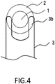
- Fig. 4 is a main portion enlarged plan view of the link member 3 and illustrates the planar shape of link leading end portions 3b of the link member 3 which are portions in engagement with the movable shaft 1.
- the example of Fig. 4 shows the state in which the two link leading end portions 3b are disposed in parallel, across the movable shaft 1, in the end portion of the link member 3 on the side which drives the movable shaft 1.
- a configuration is such that the end portions of the link leading end portions 3b come into contact with the switch 200 side end face of the flange 2 fixed to the movable shaft 1, pivot with the rotation shaft 3a as its fulcrum in accordance with opening operation, and push the end face of the flange 2 to the side opposite from the switch 200.
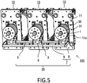
- Fig. 5 is a perspective view of the electromagnetic operation device 100 when closing as observed from the front side, wherein the grip portion 9 of the handle portion 7 is disposed exposed on the near side, and the arm portions 8 are each provided so as to connect the respective adjacent ends of the shaft 5 and grip portion 9.
- the handle portion 7 is equipped so as to be integrated with the electromagnetic operation device 100, so that there is no need to attach a handle as another member before manual operation, and it is possible to work on the manual operation immediately in the event of an emergency.
- a square frame body is configured wherein each pair of respective adjacent end portions of the shaft 5 and grip portion 9 is connected by the arm portion 8, so that it is possible to make the status of rotation of the shaft 5 more stable than when a drive force is applied only to one end of the shaft 5.
- the grip portion 9 is provided in conformity to the width of the three phases' worth of devices which the shaft 5 spans, so that it is possible to ensure a length long enough for an operator to grip the grip portion 9 naturally with both hands when in closing operation.
- a configuration is such that when opening operation starts, the operator grips the grip portion 9, applies a force downward, and starts to cause the grip portion 9 to pivot, so that it is possible for the operator to operate while placing his/her weight, and it is easy to ensure operation torque required for the manual operation for three phases all at one time.
- the electromagnetic operation device 100 of the present application has a better operability than heretofore in carrying out the manual operation with the manual operation section 20.
- Fig. 6 is an enlarged side view showing the state in which the cam 6 and the link member 3 interlock with each other.
- the cam 6 is configured of an egg-shaped plate cam having one apex portion.
- the base circle of the cam 6 is disposed concentrically with the shaft 5, and an apex portion 6a protruding by a predetermined lift amount from the base circle is attached to the shaft 5 so as to point downward when closing.
- the cam 6 shown by the broken line in Fig. 6 pivots to the position in which the apex portion 6a thereof points rightward, and the apex portion 6a comes into the state of protruding to the axial switch 200 side of the movable shaft 1.
- the link member 3 pivots counterclockwise with the rotation shaft 3a as its center (fulcrum), and one end (the lower end) of the link member 3 is pushed to the axial switch 200 side (right side) by the apex portion 6a, while the other end (the upper end) of the link member 3 is pushed to the side (left side) opposite from the axial switch 200 side of the movable shaft 1, driving the movable shaft 1 in the opening direction.
- the cams 6 mounted on the shaft 5 are individually provided on each of the three switches 200, so that the three cams 6 are mounted, separated from one another, on the shaft 5 so as to correspond to the movable shafts 1, and the three cams 6 are disposed in the same shape and in the same direction.
- the distance from the shaft 5 to the apex portion 6a (the point of load) of the cam 6 is set to be smaller than the distance from the grip portion 9 (the point of effort) of the handle portion 7 to the shaft 5 (the fulcrum), thereby enabling the cam 6 to be driven with a lower operation torque according to the principle of leverage.
- the rotation shaft 3a acting as the fulcrum of the link member 3 is disposed between the movable shaft 1 and the shaft 5.
- the rotation shaft 3a can be provided at the midpoint on the line which connects the one end (the point of effort) of the link member 3 in contact with the cam 6 and the other end (the point of load) of the link member 3 in contact with the flange 2 of the movable shaft 1, but can also be provided in another position deviated from the midpoint.
- the distance between the point of effort and the fulcrum (the rotation shaft 3a) is adjusted to be larger than the distance between the fulcrum and the point of load, thereby enabling the movable shaft 1 to move in the opening direction with a lower operation torque according to the principle of leverage.
- the distance between the point of effort and the fulcrum is adjusted to be smaller than the distance between the fulcrum and the point of load, thereby enabling the movable shaft 1 to move a larger amount through the opening operation of the movable shaft 1 by the manual operation section 20.
- the link member 3 is a component part high in the design margin which enables the shape and disposition thereof to be decided according to conditions, such as the scale and inner structure of the electromagnetic operation device 100 and the shapes of the handle portion 7 and the cam 6.
- the electromagnetic operation device 100 of the present application including the cam 6 and the link member 3 mentioned above is higher in design margin than one of the configuration in which a member (a lever in the prior art) for moving the movable shaft 1 is attached directly to the shaft 5, so that it is possible to adjust the shapes of the cam 6 and the link member 3 so as to enable the manual operation for three phases all at one time within the range of operation torque which can be ensured in the event of an emergency, and thus possible to further improve operability than heretofore.
- Fig. 7 is a front view of the electromagnetic operation device 100 in the open state as observed from the front side, wherein in the right end position of the shaft 5, a plunger 40 is fixed to the outer surface of the frame 11, and a plunger cam 41 is mounted on the shaft 5 so as to be in contact with the plunger 40.
- Fig. 8 shows a side sectional view taken along the line B-B of Fig. 7 .
- the plunger 40 having incorporated therein a compression spring 40a, is configured so as to come into contact with the plunger cam 41, thereby compressing the compression spring 40a and at the same time applying contact pressure to the plunger cam 41.
- a cam of the same shape as that of the above-described cam 6 can be used as the plunger cam 41, and the direction of the plunger cam 41 is adjusted so that the contact pressure is highest at the time halfway through opening operation.
- the pivoting range of the shaft 5 when in opening operation is 90 degrees in the same way as in the case of the first embodiment, and the plunger cam 41 is mounted on the shaft 5 so that when the handle portion 7 pivots counterclockwise from nine o' clock to six o' clock in clock position, the pivoting range of the apex portion 6a of the cam 6 interlocking with the handle portion 7 and shaft 5 is from six o'clock to three o'clock, and that the pivoting range of the apex portion of the plunger cam 41 is, for example, shifted 45 degrees counterclockwise as compared with that of the cam 6.
- a configuration is such that in the position of the middle of the pivoting range of the shaft 5 when in opening operation, the apex portion of the plunger cam 41 comes into contact with the plunger 40 and compresses the compression spring 40a, so that in the latter half portion of the pivoting range of the shaft 5 in which the apex portion of the plunger cam 41 exceeds the plunger 40, the contact pressure of the compression spring 40a incorporated in the plunger 40 acts so as for the plunger cam 41 to assist opening operation. Accordingly, it is easy to carry out the manual opening operation for the three phases' worth of switches 200 all at one time without depending only on the operator's operational force of operating the handle portion 7.
- the contact pressure of the plunger 40 is highest in the intermediate position of the pivoting range of the shaft 5, so that it is possible to inhibit the movable shaft 1 which has once come into the open state from returning to the closed state and stably hold the open state.
- the contact pressure of the plunger 40 increases gradually as opening operation proceeds, so that when opening operation starts, a force acts such as to restore the handle portion 7 to its previous closed state. Therefore, even though a load is mistakenly put on the handle portion 7, the plunger 40 acts so as to hold the closed state, and it is possible to prevent malfunction.
Landscapes
- Physics & Mathematics (AREA)
- Electromagnetism (AREA)
- Driving Mechanisms And Operating Circuits Of Arc-Extinguishing High-Tension Switches (AREA)
Abstract
Description
- The present application relates to the field of an electromagnetic operation device which operates, for example, a switch.
- As a switch, there is a vacuum circuit breaker which has incorporated in a vacuum container thereof a movable contact and a fixed contact, wherein opening/closing operation is carried out by causing the movable contact to move. An electromagnetic operation device which operates the switch is configured so as to enable not only electromagnetic operation but manual operation. When manually carrying out opening operation, for example, an operator causes a rotation shaft to pivot, thereby driving a lever fixed to the rotation shaft, and the lever directly pushes a movable shaft of the electromagnetic operation device, thus driving the device. Also, the rotation shaft is configured to be driven using a tool, such as a wrench (for example, refer to PTL 1).
- Also, as a heretofore known switching apparatus, a configuration is disclosed such as to carry out opening/closing operation for three phases' worth of switch portions (switches) all at one time, wherein a handle as another part is mounted on a main shaft (a rotation shaft) when in manual operation, and a drive shaft (a movable shaft) is directly driven with a lever fixed to the main shaft (for example, refer to PTL 2).
-
- PTL 1:
Japanese Patent No. 5,901,351 - PTL 2:
Japanese Patent No. 4,668,165 - The electromagnetic operation device of
PTL 1 is such that a mechanism portion for manual operation is provided paired with the electromagnetic operation device. For this reason, when a configuration is assumed in which three phases' worth of switches are included in one switching apparatus and an electromagnetic operation device is provided for each of the three phases, it is necessary to carry out manual operation per phase when carrying out manual opening operation, so that an open phase state occurs temporarily. - Also, in the configurations of
PTLs - The present application has been made to solve the problem, and an object of the present application is to provide an electromagnetic operation device which enables manual operation to be carried out for a plurality of switches all at one time and also which is superior in operability.
- An electromagnetic operation device disclosed in the present application includes a manual operation section with which to manually carry out opening operation for a plurality of switches all at one time, wherein the manual operation section includes a shaft which, being pivotably held on a frame of an electromagnetic operation device main body section which operates each of the switches, is disposed spanning a region in which are aligned a plurality of the electromagnetic operation device main body sections; a handle portion having a grip portion with which to pivotally operate the shaft; a plurality of cams which are individually mounted on the shaft so as to correspond to each of the plurality of electromagnetic operation device main body sections; and a link member which, being provided between the shaft and a movable shaft of each of the electromagnetic operation device main body sections, is pivotably supported on a rotation shaft supported on the frame, and one end portion and the other end portion of which are in contact respectively with the cam and with the movable shaft, wherein a configuration is such as to cause the shaft to pivot in accordance with opening operation of the handle portion, causing a plurality of the movable shafts to move at the same time via the cams and the link members.
- According to the electromagnetic operation device disclosed in the present application, a configuration is such that the cam mounted on the shaft is interlocked with the link member, causing the movable shaft to move, so that design margin is higher by the amount equivalent to a larger number of parts interlocking with the shaft than in the case of a configuration in which one member for causing the movable shaft to move is directly mounted on the shaft, and it is easy to adjust the operation torque necessary for manual operation, so that it is possible to operate a plurality of movable shafts all at one time by manually operating the handle portion fixed to the shaft, and thus possible to improve operability.
-
- [
Fig. 1] Fig. 1 is a partial sectional side view showing the outline of an electromagnetic operation device according to a first embodiment. - [
Fig. 2] Fig. 2 is an enlarged side sectional view of the electromagnetic operation device. - [
Fig. 3] Fig. 3 is a front view of the electromagnetic operation device according to the first embodiment. - [
Fig. 4] Fig. 4 is a main portion enlarged plan view of a link member. - [
Fig. 5] Fig. 5 is a perspective view of the electromagnetic operation device according to the first embodiment. - [
Fig. 6] Fig. 6 is a side view showing a cam and the link member. - [
Fig. 7] Fig. 7 is a front view of an electromagnetic operation device according to a second embodiment. - [
Fig. 8] Fig. 8 is a side sectional view taken along the line B-B ofFig. 7 . - A description will be given, using
Figs. 1 to 6 , of anelectromagnetic operation device 100 according to a first embodiment of the present application. -
Fig. 1 is a partial sectional side view showing theelectromagnetic operation device 100 according to the first embodiment, the view showing the relation of connection thereof to aswitch 200, opening/closing operation of which is performed by theelectromagnetic operation device 100. Herein, theswitch 200 is, for example, a vacuum circuit breaker, and a switching apparatus is configured of theelectromagnetic operation device 100 and theswitch 200. - The
electromagnetic operation device 100 includes an electromagnetic operation devicemain body section 10, which electromagnetically operates theswitch 200 when a power source can be used, and amanual operation section 20 used for an operator to manually operate theswitch 200 in the event of an emergency, such as a power failure. InFig. 1 , the electromagnetic operation devicemain body section 10 is disposed in the central portion, theswitch 200 is disposed on the right side, themanual operation section 20 is disposed on the left side, and amovable shaft 1 is disposed extending in the left/right direction so as to penetrate these sections. Three phases' worth ofswitches 200 are disposed aligned on the depth side ofFig. 1 , and the face portion at the left end ofFig. 1 is the front of theelectromagnetic operation device 100. - The
switch 200 is configured so that amovable contact 201 and a fixedcontact 202 axially abut each other in a vacuum container, and opening/closing of theswitch 200 is controlled by themovable shaft 1 connected to themovable contact 201 being operated by the electromagnetic operation devicemain body section 10 or themanual operation section 20. InFig. 1 , components, such as an insulating portion positioned between themovable contact 201 and the electromagnetic operation devicemain body section 10 and a conductive portion connected to the two contacts, are omitted from description. -
Fig. 2 is an enlarged side sectional view of theelectromagnetic operation device 100, and illustrates the configuration of the electromagnetic operation devicemain body section 10 with which to drive themovable shaft 1 through electromagnetic operation and the detailed configuration of themanual operation section 20 with which to manually drive themovable shaft 1.Fig. 2 corresponds to a side sectional view taken along the line A-A ofFig. 3 to be described later. - The electromagnetic operation device
main body section 10, being a mechanism section which carries out opening/closing operation for theswitch 200 during a usual operation, includes, inside two opposed plate-like frames 11 supported by aframe support portion 11b, a movingcore 12 which, being fixed to themovable shaft 1, is configured to move axially through opening/closing operation and afixed core 13 which is fixed to theframe 11 and provided opposite the movingcore 12. The movingcore 12 is operated depending on the energized state of acoil 14, and when causing a transition from a closed state to an open state, the movingcore 12 moves in the open direction (to the left side) shown by the arrow inFig. 1 and separates from thefixed core 13. When the movingcore 12 separates from thefixed core 13 and a gap occurs between the two cores, themovable shaft 1 is caused to move in the open direction (tripping direction) by aspring member 30 provided in the end portion (the left end portion) of themovable shaft 1 on the side opposite from theswitch 200, and themovable contact 201 of theswitch 200 separates from thefixed contact 202 and comes into the open state. Aspring retainer plate 31 with which to retain thespring member 30 is disposed in the end portion of themoveable shaft 1. - The
manual operation section 20 is a mechanism section with which to switch theswitch 200 from the closed state to the open state through the operator's manual operation. As shown inFig. 2 , themanual operation section 20 is provided in one end portion of themovable shaft 1 in which thespring member 30 is disposed, that is, in the end portion on the side not connected to theswitch 200. Then, themanual operation section 20 is configured mainly of alink member 3 which axially pushes aflange 2 fixed to the outer peripheral portion of themovable shaft 1, arotation shaft 3a which pivotably supports thelink member 3, ashaft support portion 4 supported on theframe 11, ashaft 5 pivotably supported in theshaft support portion 4, acam 6 which, being fixed to theshaft 5, is in contact with thelink member 3, and ahandle portion 7 formed of anarm portion 8 extending radially outward from theshaft 5 and agrip portion 9 attached to the radially outward end portion of thearm portion 8. - To give a further description, the
shaft 5 is disposed spanning a region in which are aligned the three phases' worth of electromagnetic operation devicemain body sections 10, and three cams are mounted on the oneshaft 5 so as to correspond to each of the three phases' worth of electromagnetic operation devicemain body sections 10. - Furthermore, the
link member 3, being provided between theshaft 5 and themovable shaft 1 of each of the electromagnetic operation devicemain body sections 10, is pivotably supported on therotation shaft 3a supported on theframe 11, and one end portion of thelink member 3 is in contact with thecam 6, while the other end is in contact with theflange 2 integrally fixed to themovable shaft 1. Thelink member 3, being a member which conveys the movement of thecam 6, is formed to dimensions corresponding to the distance between theshaft 5 and themovable shaft 1. The example ofFig. 2 shows thelink member 3, the planar shape of which is arcuate, the end portions of which are shaped to protrude to theflange 2 and cam 6 sides, and which has a flat joint surface which comes into contact with thecam 6. - The
electromagnetic operation device 100 of the present application is configured so that theshaft 5 is caused to pivot in accordance with opening operation of thehandle portion 7, and the three phases' worth ofmovable shafts 1 are caused to move at the same time via thecams 6 and thelink members 3, thus manually carrying out opening operation for three phases all at one time. -
Fig. 3 is a front view of theelectromagnetic operation device 100 in the closed state as observed from the front side. As shown inFig. 3 , the three phases' worth of electromagnetic operation devicemain body sections 10 are aligned in a line along the axial direction (the left/right direction) of theshaft 5, wherein themovable shafts 1 provided individually in each of the electromagnetic operation devicemain body sections 10 are disposed in parallel separated from one another, and themovable shafts 1 and theshaft 5 are disposed separated so as to ensure a constant distance for causing thelink members 3 to pivot. InFig. 3 , the threemovable shafts 1 extend in the depth direction, and onelinear grip portion 9 of thehandle portion 7 of themanual operation section 20 is held parallel to theshaft 5 below themovable shafts 1. - Then, in order to make the operator's handle operation easier, the
grip portion 9 of themanual operation section 20 is provided exposed on the front side of thetabular frame 11 and is held so as to protrude to the near side of the operator when closing, thus providing a layout superior in operability. - For example, when closing the
switch 200, thegrip portion 9 is held in the state of protruding to the near side of theshaft 5, so that thearm portion 8 extending in the radial direction of theshaft 5 comes into the state of extending in a horizontal direction, and when the range of operation through opening operation is 90 degrees in terms of the angle of rotation of theshaft 5, at the end of the opening operation, as shown by the broken line inFig. 1 , thegrip portion 9 is disposed below theshaft 5, and thearm portion 8 comes into the state of extending downward from theshaft 5. - A configuration can also be adopted such that a stopper or the like (not shown) which has the function of holding the position of the
handle portion 7 is provided, preventing thehandle portion 7 from moving downward under its own weight. - Also, the
handle portion 7 is adjusted to a weight such as to enable thehandle portion 7 to be prevented from pivoting under its own weight. Then, when in the closed state, themovable shaft 1 is pushed to theswitch 200 side by the electromagnetic devicemain body section 10, so that thehandle portion 7 is configured not to pivot downward spontaneously. - Also, as shown in
Fig. 3 , therotation shaft 3a for pivotably holding thelink member 3 is spanned between twoframe base portions 11a, which are fixed to the surface portion of theframe 11, across themovable shaft 1. The direction in which therotation shaft 3a extends is perpendicular to the direction in which the axis of themovable shaft 1 extends, and the distance between therotation shaft 3a and themovable shaft 1 is adjusted depending on the dimensions of thelink member 3. -
Fig. 4 is a main portion enlarged plan view of thelink member 3 and illustrates the planar shape of link leadingend portions 3b of thelink member 3 which are portions in engagement with themovable shaft 1. The example ofFig. 4 shows the state in which the two link leadingend portions 3b are disposed in parallel, across themovable shaft 1, in the end portion of thelink member 3 on the side which drives themovable shaft 1. A configuration is such that the end portions of the link leadingend portions 3b come into contact with theswitch 200 side end face of theflange 2 fixed to themovable shaft 1, pivot with therotation shaft 3a as its fulcrum in accordance with opening operation, and push the end face of theflange 2 to the side opposite from theswitch 200. -
Fig. 5 is a perspective view of theelectromagnetic operation device 100 when closing as observed from the front side, wherein thegrip portion 9 of thehandle portion 7 is disposed exposed on the near side, and thearm portions 8 are each provided so as to connect the respective adjacent ends of theshaft 5 andgrip portion 9. Thehandle portion 7 is equipped so as to be integrated with theelectromagnetic operation device 100, so that there is no need to attach a handle as another member before manual operation, and it is possible to work on the manual operation immediately in the event of an emergency. - Also, a square frame body is configured wherein each pair of respective adjacent end portions of the
shaft 5 andgrip portion 9 is connected by thearm portion 8, so that it is possible to make the status of rotation of theshaft 5 more stable than when a drive force is applied only to one end of theshaft 5. Furthermore, thegrip portion 9 is provided in conformity to the width of the three phases' worth of devices which theshaft 5 spans, so that it is possible to ensure a length long enough for an operator to grip thegrip portion 9 naturally with both hands when in closing operation. Then, a configuration is such that when opening operation starts, the operator grips thegrip portion 9, applies a force downward, and starts to cause thegrip portion 9 to pivot, so that it is possible for the operator to operate while placing his/her weight, and it is easy to ensure operation torque required for the manual operation for three phases all at one time. - In this way, the
electromagnetic operation device 100 of the present application has a better operability than heretofore in carrying out the manual operation with themanual operation section 20. - Next, a description will be given, using
Fig. 6 , of the operation of thecam 6 and thelink member 3 when in opening operation.Fig. 6 is an enlarged side view showing the state in which thecam 6 and thelink member 3 interlock with each other. - In this example, the
cam 6 is configured of an egg-shaped plate cam having one apex portion. The base circle of thecam 6 is disposed concentrically with theshaft 5, and anapex portion 6a protruding by a predetermined lift amount from the base circle is attached to theshaft 5 so as to point downward when closing. When theshaft 5 rotates 90 degrees counterclockwise through opening operation, thecam 6 shown by the broken line inFig. 6 pivots to the position in which theapex portion 6a thereof points rightward, and theapex portion 6a comes into the state of protruding to theaxial switch 200 side of themovable shaft 1. In accordance with this, thelink member 3 pivots counterclockwise with therotation shaft 3a as its center (fulcrum), and one end (the lower end) of thelink member 3 is pushed to theaxial switch 200 side (right side) by theapex portion 6a, while the other end (the upper end) of thelink member 3 is pushed to the side (left side) opposite from theaxial switch 200 side of themovable shaft 1, driving themovable shaft 1 in the opening direction. - The
cams 6 mounted on theshaft 5 are individually provided on each of the threeswitches 200, so that the threecams 6 are mounted, separated from one another, on theshaft 5 so as to correspond to themovable shafts 1, and the threecams 6 are disposed in the same shape and in the same direction. - Also, the distance from the
shaft 5 to theapex portion 6a (the point of load) of thecam 6 is set to be smaller than the distance from the grip portion 9 (the point of effort) of thehandle portion 7 to the shaft 5 (the fulcrum), thereby enabling thecam 6 to be driven with a lower operation torque according to the principle of leverage. - Herein, the
rotation shaft 3a acting as the fulcrum of thelink member 3 is disposed between themovable shaft 1 and theshaft 5. Therotation shaft 3a can be provided at the midpoint on the line which connects the one end (the point of effort) of thelink member 3 in contact with thecam 6 and the other end (the point of load) of thelink member 3 in contact with theflange 2 of themovable shaft 1, but can also be provided in another position deviated from the midpoint. For example, in thelink member 3, the distance between the point of effort and the fulcrum (therotation shaft 3a) is adjusted to be larger than the distance between the fulcrum and the point of load, thereby enabling themovable shaft 1 to move in the opening direction with a lower operation torque according to the principle of leverage. Conversely, the distance between the point of effort and the fulcrum is adjusted to be smaller than the distance between the fulcrum and the point of load, thereby enabling themovable shaft 1 to move a larger amount through the opening operation of themovable shaft 1 by themanual operation section 20. - In this way, the
link member 3 is a component part high in the design margin which enables the shape and disposition thereof to be decided according to conditions, such as the scale and inner structure of theelectromagnetic operation device 100 and the shapes of thehandle portion 7 and thecam 6. Then, theelectromagnetic operation device 100 of the present application including thecam 6 and thelink member 3 mentioned above is higher in design margin than one of the configuration in which a member (a lever in the prior art) for moving themovable shaft 1 is attached directly to theshaft 5, so that it is possible to adjust the shapes of thecam 6 and thelink member 3 so as to enable the manual operation for three phases all at one time within the range of operation torque which can be ensured in the event of an emergency, and thus possible to further improve operability than heretofore. - Next, a description will be given, using
Figs. 7 and8 , of anelectromagnetic operation device 100 according to a second embodiment of the present application. -
Fig. 7 is a front view of theelectromagnetic operation device 100 in the open state as observed from the front side, wherein in the right end position of theshaft 5, aplunger 40 is fixed to the outer surface of theframe 11, and aplunger cam 41 is mounted on theshaft 5 so as to be in contact with theplunger 40.Fig. 8 shows a side sectional view taken along the line B-B ofFig. 7 . - As shown in
Fig. 8 , theplunger 40, having incorporated therein acompression spring 40a, is configured so as to come into contact with theplunger cam 41, thereby compressing thecompression spring 40a and at the same time applying contact pressure to theplunger cam 41. A cam of the same shape as that of the above-describedcam 6 can be used as theplunger cam 41, and the direction of theplunger cam 41 is adjusted so that the contact pressure is highest at the time halfway through opening operation. - The pivoting range of the
shaft 5 when in opening operation is 90 degrees in the same way as in the case of the first embodiment, and theplunger cam 41 is mounted on theshaft 5 so that when thehandle portion 7 pivots counterclockwise from nine o' clock to six o' clock in clock position, the pivoting range of theapex portion 6a of thecam 6 interlocking with thehandle portion 7 andshaft 5 is from six o'clock to three o'clock, and that the pivoting range of the apex portion of theplunger cam 41 is, for example, shifted 45 degrees counterclockwise as compared with that of thecam 6. - In the
electromagnetic operation device 100 according to the second embodiment, a configuration is such that in the position of the middle of the pivoting range of theshaft 5 when in opening operation, the apex portion of theplunger cam 41 comes into contact with theplunger 40 and compresses thecompression spring 40a, so that in the latter half portion of the pivoting range of theshaft 5 in which the apex portion of theplunger cam 41 exceeds theplunger 40, the contact pressure of thecompression spring 40a incorporated in theplunger 40 acts so as for theplunger cam 41 to assist opening operation. Accordingly, it is easy to carry out the manual opening operation for the three phases' worth ofswitches 200 all at one time without depending only on the operator's operational force of operating thehandle portion 7. - The contact pressure of the
plunger 40 is highest in the intermediate position of the pivoting range of theshaft 5, so that it is possible to inhibit themovable shaft 1 which has once come into the open state from returning to the closed state and stably hold the open state. - Furthermore, in the early half portion of the pivoting range of the
shaft 5, the contact pressure of theplunger 40 increases gradually as opening operation proceeds, so that when opening operation starts, a force acts such as to restore thehandle portion 7 to its previous closed state. Therefore, even though a load is mistakenly put on thehandle portion 7, theplunger 40 acts so as to hold the closed state, and it is possible to prevent malfunction. - In this way, the contact pressure applied from the
plunger 40 is increased and reduced in the pivoting range of theshaft 5, and thereby it is also possible, while preventing malfunction, to stably hold the open state or the closed state. - Although the present application is described above in terms of various exemplary embodiments and implementations, it should be understood that the various features, aspects, and functionality described in one or more of the individual embodiments are not limited in their applicability to the particular embodiment with which they are described, but instead can be applied, alone or in various combinations, to one or more of the embodiments.
- It is therefore understood that numerous modifications which have not been exemplified can be devised without departing from the scope of the present application. For example, at least one of the constituent components may be modified, added, or eliminated. At least one of the constituent components mentioned in at least one of the preferred embodiments may be selected and combined with the constituent components mentioned in another preferred embodiment.
- 1 movable shaft, 2 flange, 3 link member, 3a rotation shaft, 3b link leading end portion, 4 shaft support portion, 5 shaft, 6 cam, 6a apex portion, 7 handle portion, 8 arm portion, 9 grip portion, 10 electromagnetic operation device main body section, 11 frame, 11a frame base portion, 11b frame support portion, 12 moving core, 13 fixed core, 14 coil, 20 manual operation section, 30 spring member, 31 spring retainer plate, 40 plunger, 40a compression spring, 41 plunger cam, 100 electromagnetic operation device, 200 switch, 201 movable contact, 202 fixed contact
Claims (5)
- An electromagnetic operation device, comprising:a manual operation section with which to manually carry out opening operation for a plurality of switches all at one time, the device being characterized in thatthe manual operation section includes:a shaft which, being pivotably held on a frame of an electromagnetic operation device main body section which operates each of the switches, is disposed spanning a region in which are aligned a plurality of the electromagnetic operation device main body sections;a handle portion having a grip portion with which to pivotally operate the shaft;a plurality of cams which are mounted on the shaft so as to correspond to each of the plurality of electromagnetic operation device main body sections; anda link member which, being provided between the shaft and a movable shaft of each of the electromagnetic operation device main body sections, is pivotably supported on a rotation shaft supported on the frame, and one end portion and the other end portion of which are in contact respectively with the cam and with the movable shaft, whereina configuration is such as to cause the shaft to pivot in accordance with opening operation of the handle portion, causing a plurality of the movable shafts to move at the same time via the cams and the link members.
- The electromagnetic operation device according to claim 1, characterized in that
the three phases' worth of electromagnetic operation device main body sections are disposed aligned along the axial direction of the shaft, and the three movable shafts individually provided in each of the electromagnetic operation device main body sections are disposed in parallel separated from one another. - The electromagnetic operation device according to claim 1 or 2, characterized in that
the handle portion is configured of the one grip portion provided in parallel to the shaft and of arm portions which connect the shaft and the grip portion, and the grip portion is disposed in the state of being exposed on the front side of the electromagnetic operation device. - The electromagnetic operation device according to claim 3, characterized in that
the grip portion of the handle portion is configured, when closing, to be held on the near side of the shaft in the front of the electromagnetic operation device, and when opening starts, to be pushed downward and pivot around the shaft. - The electromagnetic operation device according to any one of claims 1 to 4, characterized in thatthe manual operation section includes a plunger which, having incorporated therein a compression spring, is fixed to the frame and a plunger cam which, interlocking with the plunger, is fixed to the shaft, whereina configuration is such that in the intermediate position of a rotation range of the shaft when in opening operation, the apex portion of the plunger cam comes into contact with the plunger and compresses the compression spring.
Applications Claiming Priority (1)
| Application Number | Priority Date | Filing Date | Title |
|---|---|---|---|
| PCT/JP2019/015294 WO2020208676A1 (en) | 2019-04-08 | 2019-04-08 | Electromagnetic operating apparatus |
Publications (3)
| Publication Number | Publication Date |
|---|---|
| EP3955273A1 true EP3955273A1 (en) | 2022-02-16 |
| EP3955273A4 EP3955273A4 (en) | 2022-08-03 |
| EP3955273B1 EP3955273B1 (en) | 2024-08-14 |
Family
ID=68763513
Family Applications (1)
| Application Number | Title | Priority Date | Filing Date |
|---|---|---|---|
| EP19924617.4A Active EP3955273B1 (en) | 2019-04-08 | 2019-04-08 | Electromagnetic operating apparatus |
Country Status (5)
| Country | Link |
|---|---|
| EP (1) | EP3955273B1 (en) |
| JP (1) | JP6615426B1 (en) |
| CN (1) | CN113614869B (en) |
| TW (1) | TWI734165B (en) |
| WO (1) | WO2020208676A1 (en) |
Family Cites Families (14)
| Publication number | Priority date | Publication date | Assignee | Title |
|---|---|---|---|---|
| DE4311958C2 (en) * | 1993-04-10 | 1995-04-20 | Felten & Guilleaume Energie | Electromagnetic switching mechanism for electrical protective switching devices |
| JP3861832B2 (en) * | 2003-03-11 | 2006-12-27 | 株式会社日立製作所 | Switch |
| US7239490B2 (en) * | 2003-09-22 | 2007-07-03 | Eaton Corporation | Medium voltage vacuum circuit interrupter |
| US7576957B2 (en) * | 2006-05-01 | 2009-08-18 | Eaton Corporation | Circuit interrupter including point-on-wave controller and voltage sensors |
| US7545245B2 (en) * | 2006-05-01 | 2009-06-09 | Eaton Corporation | Manual opening device and electrical switching apparatus employing the same |
| JP4668165B2 (en) | 2006-12-20 | 2011-04-13 | 三菱電機株式会社 | Switchgear |
| JP4872756B2 (en) * | 2007-03-30 | 2012-02-08 | 三菱電機株式会社 | External operation handle device for switch |
| JP5093081B2 (en) * | 2008-12-08 | 2012-12-05 | 日新電機株式会社 | Electromagnetic actuator |
| US8729985B2 (en) * | 2012-01-23 | 2014-05-20 | Electro-Mechanical Corporation | Switchgear visible disconnect mechanical interlock |
| JP5901351B2 (en) | 2012-03-01 | 2016-04-06 | 三菱電機株式会社 | Electromagnetic operation device |
| JP5859146B2 (en) * | 2013-01-11 | 2016-02-10 | 三菱電機株式会社 | Manual opening / closing device of electromagnetic operation mechanism |
| US9196438B2 (en) * | 2013-07-26 | 2015-11-24 | Quality Switch, Inc. | Safety system for high voltage network grounding switch |
| US9490084B2 (en) * | 2014-11-13 | 2016-11-08 | Eaton Corporation | Visible disconnect switch interlock assembly |
| CN106356208B (en) * | 2016-11-25 | 2018-03-16 | 贵州泰永长征技术股份有限公司 | Dual-power transfer switch electrical equipment is pressed in a kind of permanent magnetism |
-
2019
- 2019-04-08 EP EP19924617.4A patent/EP3955273B1/en active Active
- 2019-04-08 WO PCT/JP2019/015294 patent/WO2020208676A1/en not_active Ceased
- 2019-04-08 CN CN201980094577.4A patent/CN113614869B/en active Active
- 2019-04-08 JP JP2019547336A patent/JP6615426B1/en active Active
- 2019-08-12 TW TW108128448A patent/TWI734165B/en active
Also Published As
| Publication number | Publication date |
|---|---|
| JPWO2020208676A1 (en) | 2021-04-30 |
| WO2020208676A1 (en) | 2020-10-15 |
| EP3955273A4 (en) | 2022-08-03 |
| TWI734165B (en) | 2021-07-21 |
| CN113614869A (en) | 2021-11-05 |
| CN113614869B (en) | 2024-12-10 |
| TW202038276A (en) | 2020-10-16 |
| JP6615426B1 (en) | 2019-12-04 |
| EP3955273B1 (en) | 2024-08-14 |
Similar Documents
| Publication | Publication Date | Title |
|---|---|---|
| US4392036A (en) | Low-voltage protective circuit breaker with a forked locking lever | |
| US6515245B2 (en) | Closing assistance mechanism for an electrical switchgear apparatus and drive mechanism of an electrical switchgear apparatus equipped with such an assistance mechanism | |
| EP0450699A2 (en) | Enabling means for locking, by a padlock, hand control devices of electromechanical equipments | |
| EP2892069B1 (en) | Interlocking apparatus of transfer switch | |
| US20160141122A1 (en) | Interlock for circuit interrupting device | |
| EP2270823B1 (en) | Multi-phase medium voltage contactor | |
| KR20140112503A (en) | Mobile conducting unit for a breaker, including a spring for accelerating the separation of arc contacts | |
| US20160111229A1 (en) | Electrical switching apparatus and transmission assembly therefor | |
| US10643813B2 (en) | Automatic transfer switch with permanent magnetic actuation | |
| US9275807B2 (en) | Interlock system for switchgear | |
| EP3955273A1 (en) | Electromagnetic operating apparatus | |
| CN102598178B (en) | For the drive unit of multi-position switch equipment | |
| US6815623B1 (en) | Double throw switch linkage | |
| KR101015276B1 (en) | Elastic pressure unit and wiring breaker having same | |
| US6872900B1 (en) | Double throw switch linkage | |
| WO2006067936A1 (en) | Grounding switch-equipped gas insulation switch device | |
| JPH05144361A (en) | Thermal relay | |
| KR200377715Y1 (en) | A Connecting Device Between Cubicle Type SF6 Gas Insulated Switchgear And Vacuum Interupter | |
| CN114649171B (en) | breaker | |
| CN112309792B (en) | Extreme motion booster mechanism | |
| CN1967763B (en) | Electrical switching device | |
| EP3439014A1 (en) | Couplable actuation mechanism for moulded-case circuit-breakers | |
| WO2013044990A1 (en) | Actuating device for a current switching device | |
| JPH0145930B2 (en) | ||
| HK1106868B (en) | Electrical switching device |
Legal Events
| Date | Code | Title | Description |
|---|---|---|---|
| STAA | Information on the status of an ep patent application or granted ep patent |
Free format text: STATUS: THE INTERNATIONAL PUBLICATION HAS BEEN MADE |
|
| PUAI | Public reference made under article 153(3) epc to a published international application that has entered the european phase |
Free format text: ORIGINAL CODE: 0009012 |
|
| STAA | Information on the status of an ep patent application or granted ep patent |
Free format text: STATUS: REQUEST FOR EXAMINATION WAS MADE |
|
| 17P | Request for examination filed |
Effective date: 20210728 |
|
| AK | Designated contracting states |
Kind code of ref document: A1 Designated state(s): AL AT BE BG CH CY CZ DE DK EE ES FI FR GB GR HR HU IE IS IT LI LT LU LV MC MK MT NL NO PL PT RO RS SE SI SK SM TR |
|
| RIC1 | Information provided on ipc code assigned before grant |
Ipc: H01H 33/666 20060101AFI20220307BHEP |
|
| DAV | Request for validation of the european patent (deleted) | ||
| DAX | Request for extension of the european patent (deleted) | ||
| A4 | Supplementary search report drawn up and despatched |
Effective date: 20220630 |
|
| RIC1 | Information provided on ipc code assigned before grant |
Ipc: H01H 33/666 20060101AFI20220624BHEP |
|
| GRAP | Despatch of communication of intention to grant a patent |
Free format text: ORIGINAL CODE: EPIDOSNIGR1 |
|
| STAA | Information on the status of an ep patent application or granted ep patent |
Free format text: STATUS: GRANT OF PATENT IS INTENDED |
|
| INTG | Intention to grant announced |
Effective date: 20240312 |
|
| GRAS | Grant fee paid |
Free format text: ORIGINAL CODE: EPIDOSNIGR3 |
|
| GRAA | (expected) grant |
Free format text: ORIGINAL CODE: 0009210 |
|
| STAA | Information on the status of an ep patent application or granted ep patent |
Free format text: STATUS: THE PATENT HAS BEEN GRANTED |
|
| AK | Designated contracting states |
Kind code of ref document: B1 Designated state(s): AL AT BE BG CH CY CZ DE DK EE ES FI FR GB GR HR HU IE IS IT LI LT LU LV MC MK MT NL NO PL PT RO RS SE SI SK SM TR |
|
| REG | Reference to a national code |
Ref country code: GB Ref legal event code: FG4D |
|
| REG | Reference to a national code |
Ref country code: CH Ref legal event code: EP |
|
| REG | Reference to a national code |
Ref country code: DE Ref legal event code: R096 Ref document number: 602019057203 Country of ref document: DE |
|
| REG | Reference to a national code |
Ref country code: IE Ref legal event code: FG4D |
|
| REG | Reference to a national code |
Ref country code: LT Ref legal event code: MG9D |
|
| REG | Reference to a national code |
Ref country code: NL Ref legal event code: MP Effective date: 20240814 |
|
| PG25 | Lapsed in a contracting state [announced via postgrant information from national office to epo] |
Ref country code: NO Free format text: LAPSE BECAUSE OF FAILURE TO SUBMIT A TRANSLATION OF THE DESCRIPTION OR TO PAY THE FEE WITHIN THE PRESCRIBED TIME-LIMIT Effective date: 20241114 |
|
| REG | Reference to a national code |
Ref country code: AT Ref legal event code: MK05 Ref document number: 1714102 Country of ref document: AT Kind code of ref document: T Effective date: 20240814 |
|
| PG25 | Lapsed in a contracting state [announced via postgrant information from national office to epo] |
Ref country code: FI Free format text: LAPSE BECAUSE OF FAILURE TO SUBMIT A TRANSLATION OF THE DESCRIPTION OR TO PAY THE FEE WITHIN THE PRESCRIBED TIME-LIMIT Effective date: 20240814 Ref country code: NL Free format text: LAPSE BECAUSE OF FAILURE TO SUBMIT A TRANSLATION OF THE DESCRIPTION OR TO PAY THE FEE WITHIN THE PRESCRIBED TIME-LIMIT Effective date: 20240814 Ref country code: PL Free format text: LAPSE BECAUSE OF FAILURE TO SUBMIT A TRANSLATION OF THE DESCRIPTION OR TO PAY THE FEE WITHIN THE PRESCRIBED TIME-LIMIT Effective date: 20240814 Ref country code: GR Free format text: LAPSE BECAUSE OF FAILURE TO SUBMIT A TRANSLATION OF THE DESCRIPTION OR TO PAY THE FEE WITHIN THE PRESCRIBED TIME-LIMIT Effective date: 20241115 Ref country code: PT Free format text: LAPSE BECAUSE OF FAILURE TO SUBMIT A TRANSLATION OF THE DESCRIPTION OR TO PAY THE FEE WITHIN THE PRESCRIBED TIME-LIMIT Effective date: 20241216 |
|
| PG25 | Lapsed in a contracting state [announced via postgrant information from national office to epo] |
Ref country code: BG Free format text: LAPSE BECAUSE OF FAILURE TO SUBMIT A TRANSLATION OF THE DESCRIPTION OR TO PAY THE FEE WITHIN THE PRESCRIBED TIME-LIMIT Effective date: 20240814 |
|
| PG25 | Lapsed in a contracting state [announced via postgrant information from national office to epo] |
Ref country code: LV Free format text: LAPSE BECAUSE OF FAILURE TO SUBMIT A TRANSLATION OF THE DESCRIPTION OR TO PAY THE FEE WITHIN THE PRESCRIBED TIME-LIMIT Effective date: 20240814 |
|
| PG25 | Lapsed in a contracting state [announced via postgrant information from national office to epo] |
Ref country code: AT Free format text: LAPSE BECAUSE OF FAILURE TO SUBMIT A TRANSLATION OF THE DESCRIPTION OR TO PAY THE FEE WITHIN THE PRESCRIBED TIME-LIMIT Effective date: 20240814 Ref country code: IS Free format text: LAPSE BECAUSE OF FAILURE TO SUBMIT A TRANSLATION OF THE DESCRIPTION OR TO PAY THE FEE WITHIN THE PRESCRIBED TIME-LIMIT Effective date: 20241214 |
|
| PG25 | Lapsed in a contracting state [announced via postgrant information from national office to epo] |
Ref country code: HR Free format text: LAPSE BECAUSE OF FAILURE TO SUBMIT A TRANSLATION OF THE DESCRIPTION OR TO PAY THE FEE WITHIN THE PRESCRIBED TIME-LIMIT Effective date: 20240814 |
|
| PG25 | Lapsed in a contracting state [announced via postgrant information from national office to epo] |
Ref country code: ES Free format text: LAPSE BECAUSE OF FAILURE TO SUBMIT A TRANSLATION OF THE DESCRIPTION OR TO PAY THE FEE WITHIN THE PRESCRIBED TIME-LIMIT Effective date: 20240814 Ref country code: RS Free format text: LAPSE BECAUSE OF FAILURE TO SUBMIT A TRANSLATION OF THE DESCRIPTION OR TO PAY THE FEE WITHIN THE PRESCRIBED TIME-LIMIT Effective date: 20241114 |
|
| PG25 | Lapsed in a contracting state [announced via postgrant information from national office to epo] |
Ref country code: RS Free format text: LAPSE BECAUSE OF FAILURE TO SUBMIT A TRANSLATION OF THE DESCRIPTION OR TO PAY THE FEE WITHIN THE PRESCRIBED TIME-LIMIT Effective date: 20241114 Ref country code: PT Free format text: LAPSE BECAUSE OF FAILURE TO SUBMIT A TRANSLATION OF THE DESCRIPTION OR TO PAY THE FEE WITHIN THE PRESCRIBED TIME-LIMIT Effective date: 20241216 Ref country code: PL Free format text: LAPSE BECAUSE OF FAILURE TO SUBMIT A TRANSLATION OF THE DESCRIPTION OR TO PAY THE FEE WITHIN THE PRESCRIBED TIME-LIMIT Effective date: 20240814 Ref country code: NO Free format text: LAPSE BECAUSE OF FAILURE TO SUBMIT A TRANSLATION OF THE DESCRIPTION OR TO PAY THE FEE WITHIN THE PRESCRIBED TIME-LIMIT Effective date: 20241114 Ref country code: NL Free format text: LAPSE BECAUSE OF FAILURE TO SUBMIT A TRANSLATION OF THE DESCRIPTION OR TO PAY THE FEE WITHIN THE PRESCRIBED TIME-LIMIT Effective date: 20240814 Ref country code: LV Free format text: LAPSE BECAUSE OF FAILURE TO SUBMIT A TRANSLATION OF THE DESCRIPTION OR TO PAY THE FEE WITHIN THE PRESCRIBED TIME-LIMIT Effective date: 20240814 Ref country code: IS Free format text: LAPSE BECAUSE OF FAILURE TO SUBMIT A TRANSLATION OF THE DESCRIPTION OR TO PAY THE FEE WITHIN THE PRESCRIBED TIME-LIMIT Effective date: 20241214 Ref country code: HR Free format text: LAPSE BECAUSE OF FAILURE TO SUBMIT A TRANSLATION OF THE DESCRIPTION OR TO PAY THE FEE WITHIN THE PRESCRIBED TIME-LIMIT Effective date: 20240814 Ref country code: GR Free format text: LAPSE BECAUSE OF FAILURE TO SUBMIT A TRANSLATION OF THE DESCRIPTION OR TO PAY THE FEE WITHIN THE PRESCRIBED TIME-LIMIT Effective date: 20241115 Ref country code: FI Free format text: LAPSE BECAUSE OF FAILURE TO SUBMIT A TRANSLATION OF THE DESCRIPTION OR TO PAY THE FEE WITHIN THE PRESCRIBED TIME-LIMIT Effective date: 20240814 Ref country code: ES Free format text: LAPSE BECAUSE OF FAILURE TO SUBMIT A TRANSLATION OF THE DESCRIPTION OR TO PAY THE FEE WITHIN THE PRESCRIBED TIME-LIMIT Effective date: 20240814 Ref country code: BG Free format text: LAPSE BECAUSE OF FAILURE TO SUBMIT A TRANSLATION OF THE DESCRIPTION OR TO PAY THE FEE WITHIN THE PRESCRIBED TIME-LIMIT Effective date: 20240814 Ref country code: AT Free format text: LAPSE BECAUSE OF FAILURE TO SUBMIT A TRANSLATION OF THE DESCRIPTION OR TO PAY THE FEE WITHIN THE PRESCRIBED TIME-LIMIT Effective date: 20240814 |
|
| PG25 | Lapsed in a contracting state [announced via postgrant information from national office to epo] |
Ref country code: DK Free format text: LAPSE BECAUSE OF FAILURE TO SUBMIT A TRANSLATION OF THE DESCRIPTION OR TO PAY THE FEE WITHIN THE PRESCRIBED TIME-LIMIT Effective date: 20240814 Ref country code: RO Free format text: LAPSE BECAUSE OF FAILURE TO SUBMIT A TRANSLATION OF THE DESCRIPTION OR TO PAY THE FEE WITHIN THE PRESCRIBED TIME-LIMIT Effective date: 20240814 Ref country code: SM Free format text: LAPSE BECAUSE OF FAILURE TO SUBMIT A TRANSLATION OF THE DESCRIPTION OR TO PAY THE FEE WITHIN THE PRESCRIBED TIME-LIMIT Effective date: 20240814 |
|
| PG25 | Lapsed in a contracting state [announced via postgrant information from national office to epo] |
Ref country code: EE Free format text: LAPSE BECAUSE OF FAILURE TO SUBMIT A TRANSLATION OF THE DESCRIPTION OR TO PAY THE FEE WITHIN THE PRESCRIBED TIME-LIMIT Effective date: 20240814 |
|
| PG25 | Lapsed in a contracting state [announced via postgrant information from national office to epo] |
Ref country code: CZ Free format text: LAPSE BECAUSE OF FAILURE TO SUBMIT A TRANSLATION OF THE DESCRIPTION OR TO PAY THE FEE WITHIN THE PRESCRIBED TIME-LIMIT Effective date: 20240814 |
|
| PG25 | Lapsed in a contracting state [announced via postgrant information from national office to epo] |
Ref country code: SK Free format text: LAPSE BECAUSE OF FAILURE TO SUBMIT A TRANSLATION OF THE DESCRIPTION OR TO PAY THE FEE WITHIN THE PRESCRIBED TIME-LIMIT Effective date: 20240814 Ref country code: IT Free format text: LAPSE BECAUSE OF FAILURE TO SUBMIT A TRANSLATION OF THE DESCRIPTION OR TO PAY THE FEE WITHIN THE PRESCRIBED TIME-LIMIT Effective date: 20240814 |
|
| REG | Reference to a national code |
Ref country code: DE Ref legal event code: R097 Ref document number: 602019057203 Country of ref document: DE |
|
| PLBE | No opposition filed within time limit |
Free format text: ORIGINAL CODE: 0009261 |
|
| STAA | Information on the status of an ep patent application or granted ep patent |
Free format text: STATUS: NO OPPOSITION FILED WITHIN TIME LIMIT |
|
| PGFP | Annual fee paid to national office [announced via postgrant information from national office to epo] |
Ref country code: DE Payment date: 20250305 Year of fee payment: 7 |
|
| 26N | No opposition filed |
Effective date: 20250515 |
|
| PG25 | Lapsed in a contracting state [announced via postgrant information from national office to epo] |
Ref country code: SE Free format text: LAPSE BECAUSE OF FAILURE TO SUBMIT A TRANSLATION OF THE DESCRIPTION OR TO PAY THE FEE WITHIN THE PRESCRIBED TIME-LIMIT Effective date: 20240814 |
|
| P01 | Opt-out of the competence of the unified patent court (upc) registered |
Free format text: CASE NUMBER: UPC_APP_4938_3955273/2025 Effective date: 20250827 |
|
| REG | Reference to a national code |
Ref country code: CH Ref legal event code: H13 Free format text: ST27 STATUS EVENT CODE: U-0-0-H10-H13 (AS PROVIDED BY THE NATIONAL OFFICE) Effective date: 20251125 |
|
| PG25 | Lapsed in a contracting state [announced via postgrant information from national office to epo] |
Ref country code: LU Free format text: LAPSE BECAUSE OF NON-PAYMENT OF DUE FEES Effective date: 20250408 |
|
| PG25 | Lapsed in a contracting state [announced via postgrant information from national office to epo] |
Ref country code: MC Free format text: LAPSE BECAUSE OF FAILURE TO SUBMIT A TRANSLATION OF THE DESCRIPTION OR TO PAY THE FEE WITHIN THE PRESCRIBED TIME-LIMIT Effective date: 20240814 |
|
| GBPC | Gb: european patent ceased through non-payment of renewal fee |
Effective date: 20250408 |
|
| REG | Reference to a national code |
Ref country code: BE Ref legal event code: MM Effective date: 20250430 |
|
| PG25 | Lapsed in a contracting state [announced via postgrant information from national office to epo] |
Ref country code: GB Free format text: LAPSE BECAUSE OF NON-PAYMENT OF DUE FEES Effective date: 20250408 |
|
| PG25 | Lapsed in a contracting state [announced via postgrant information from national office to epo] |
Ref country code: BE Free format text: LAPSE BECAUSE OF NON-PAYMENT OF DUE FEES Effective date: 20250430 |
|
| PG25 | Lapsed in a contracting state [announced via postgrant information from national office to epo] |
Ref country code: CH Free format text: LAPSE BECAUSE OF NON-PAYMENT OF DUE FEES Effective date: 20250430 |
|
| PG25 | Lapsed in a contracting state [announced via postgrant information from national office to epo] |
Ref country code: IE Free format text: LAPSE BECAUSE OF NON-PAYMENT OF DUE FEES Effective date: 20250408 |
|
| PGFP | Annual fee paid to national office [announced via postgrant information from national office to epo] |
Ref country code: FR Payment date: 20260309 Year of fee payment: 8 |