EP3955047A1 - Near-eye system having polarization waveguide - Google Patents
Near-eye system having polarization waveguide Download PDFInfo
- Publication number
- EP3955047A1 EP3955047A1 EP21193118.3A EP21193118A EP3955047A1 EP 3955047 A1 EP3955047 A1 EP 3955047A1 EP 21193118 A EP21193118 A EP 21193118A EP 3955047 A1 EP3955047 A1 EP 3955047A1
- Authority
- EP
- European Patent Office
- Prior art keywords
- light
- polarization
- waveguide
- coupling interface
- display
- Prior art date
- Legal status (The legal status is an assumption and is not a legal conclusion. Google has not performed a legal analysis and makes no representation as to the accuracy of the status listed.)
- Pending
Links
Images


Classifications
-
- G—PHYSICS
- G02—OPTICS
- G02B—OPTICAL ELEMENTS, SYSTEMS OR APPARATUS
- G02B27/00—Optical systems or apparatus not provided for by any of the groups G02B1/00 - G02B26/00, G02B30/00
- G02B27/01—Head-up displays
- G02B27/017—Head mounted
- G02B27/0172—Head mounted characterised by optical features
-
- G—PHYSICS
- G02—OPTICS
- G02B—OPTICAL ELEMENTS, SYSTEMS OR APPARATUS
- G02B27/00—Optical systems or apparatus not provided for by any of the groups G02B1/00 - G02B26/00, G02B30/00
- G02B27/28—Optical systems or apparatus not provided for by any of the groups G02B1/00 - G02B26/00, G02B30/00 for polarising
- G02B27/283—Optical systems or apparatus not provided for by any of the groups G02B1/00 - G02B26/00, G02B30/00 for polarising used for beam splitting or combining
-
- G—PHYSICS
- G02—OPTICS
- G02B—OPTICAL ELEMENTS, SYSTEMS OR APPARATUS
- G02B5/00—Optical elements other than lenses
- G02B5/30—Polarising elements
- G02B5/3083—Birefringent or phase retarding elements
-
- G—PHYSICS
- G02—OPTICS
- G02B—OPTICAL ELEMENTS, SYSTEMS OR APPARATUS
- G02B27/00—Optical systems or apparatus not provided for by any of the groups G02B1/00 - G02B26/00, G02B30/00
- G02B27/01—Head-up displays
- G02B27/017—Head mounted
- G02B2027/0178—Eyeglass type
Definitions
- Near-eye display systems typically employ a waveguide (also frequently referred to as a "lightguide") to convey light emitted by a display to a user's eye.
- the waveguide relies on total internal reflection (TIR) to convey light received from the display via in-coupling optics at one end of the waveguide to out-coupling optics facing the user's eye on the other end of the waveguide.
- TIR total internal reflection
- Such waveguides must be composed of material with a high index of refraction.
- implementation of such materials can be problematic.
- the field of view (FOV) provided by a conventional TIR-based waveguide is inversely proportional to the index of refraction of the material of the waveguide, and thus the high index of refraction needed to achieve TIR impedes the FOV that can be provided by the waveguide, which typically is no more than 50 degrees.
- waveguide materials with higher indices of refraction tend to be both heavier and more expensive than materials with lower indexes of refraction, and consequently conventional TIR-based waveguides tend to be more expensive and heavier.
- systems employing TIR-based waveguides often must be sealed in order to reduce the risk of contamination of the surface of the waveguide, which can break the TIR condition and lead to light leakage. The mechanisms used to provide this seal often increase the cost, weight, and complexity of the system and are prone to failure.
- FIGs. 1-9 illustrate example implementations of a polarization waveguide for use in a near-eye display system.
- the near-eye display system uses the polarization waveguide (PWG) to convey light representative of display images from a micro-display or other display to a wearer's eye.
- PWG polarization waveguide
- the PWG does not rely on TIR, but instead conveys a representation of the display light from an in-coupling interface facing the display to an out-coupling interface facing an eye through multiple changes of the polarization state of the representative light as it traverses the polarization waveguide, where at least a subset of these changes in the polarization state induce reflection of the representative light within the PWG.
- TIR total internal reflection
- the changes in polarization state of the representative light from receipt of the display light at the in-coupling interface to a light extraction component of the polarization waveguide are implemented so as to facilitate reflection of the representative light due to its particular polarization state at a corresponding layer interface of the PWG.
- the light extraction component reflects the light toward the out-coupling interface, and in doing so changes the polarization state of the reflected light so as to permit the reflect light to traverse the layers of the PWG that served to reflect the light when the conveyed light was in other polarization states, and thus allowing the reflected light ultimately to emerge from the PWG at the out-coupling interface in an eyeward direction.
- the PWG By manipulating the polarization state of the display light to enable reflection of the display light within the PWG until it is ultimately redirected eyeward, the PWG is able to convey the display light from the in-coupling interface to the out-coupling interface in a manner that is not reliant on total internal reflection (TIR), in contrast to conventional near-eye waveguides.
- TIR total internal reflection
- the waveguide substrate of the PWG which serves as the primary conduit for the display light between in-coupling and out-coupling can be implemented using optically transparent material with a lower index of refraction than the waveguide material used in conventional TIR-based waveguides, while also providing a higher FOV than such conventional waveguides for a material with a given index of refraction.
- the PWG may be lighter and less expensive to manufacture.
- the PWG may be implemented in a form factor that has non-parallel major surfaces or is non-planar.
- the PWG could be implemented in a form factor with one or both major surfaces being curved surfaces, and as such can be implemented to provide a non-zero optical power or implemented within an eyeglass lens fitted to an eyeglass frame.
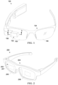
- FIG. 1 illustrates an example near-eye display system 100 employing a polarization waveguide (PWG) 102 in accordance with at least one embodiment.
- the system 100 is implemented in an eyeglass form factor having an eyeglass frame 104 with eyeglass lenses 105, 106 for a wearer's right eye and left eye, respectively.
- the PWG 102 is separate from the eyeglass lenses and instead overlies one of the eyeglass lenses (eyeglass lens 105 in this instance) such that an out-coupling interface (described in greater detail below with reference to FIG. 3 ) of the PWG 102 faces the expected position of the corresponding eye of the wearer.
- the PWG 102 is mounted to the eyeglass frame 104 via a waveguide mount housing 109, which also serves to house some or all of the electronic components (not illustrated in FIG. 1 ) of the near-eye display system 100, such as a display that generates augmented reality (AR) or (VR) imagery for display to the wearer via the PWG 102, an in-coupling optic to direct light from the display to an in-coupling interface of the PWG 102, one or more processors, wireless interfaces, batteries or other power sources, and the like. A number of these components are described in greater detail below.
- FIG. 2 illustrates another example near-eye display system 200 employing a PWG 202 in accordance with at least one embodiment.
- the system 200 employs an eyeglass form factor with an eyeglass frame 204 having eyeglass lenses 205, 206.
- the system 200 implements the PWG 202 using the eyeglass lens 205. That is, the PWG 202 is integrated within the eyeglass lens 205, and thus allowing the near-eye display system 200 to have a more traditional eyeglass appearance.
- a display housing (omitted from FIG.
- the eyeglass lens 206 on the eyeglass frame 204 at the distal periphery of the eyeglass lens 205 contains a micro-display or other display to emit display light representative of AR or VR imagery and in-coupling optic to direct the emitted display light to an in-coupling interface of the PWG 202 in the lens 205, whereupon the display light is propagated through the PWG 202/eyeglass lens 205 toward an out-coupling interface 207 that is located in the eyeglass lens 205/PWG 202 so as to be aligned with an expected position (or expected range of positions) of a corresponding eye of the wearer.
- the eyeglass lens 206 likewise implements a corresponding PWG and the system 200 employs corresponding display componentry in the same manner to provide for the display of AR or VR imagery to the other eye of the wearer as well.
- the PWG 102 of system 100 of FIG. 1 and the PWG 202 of system 200 of FIG. 2 each operates to convey display light from a proximate display to an eye of the user via multiple reflections of the display light within the body of the PWG as the display light traverses from one end of the PWG proximate to the display to the opposing end of the PWG facing an eye of the wearer.
- these reflections do not rely on TIR; that is, the angle of incidence may be less than the critical angle of the interface between mediums at the point of reflection.
- the PWG instead manipulates the polarization state of the display light as it propagates through the PWG so as to cause the display light to reflect one or more times within the PWG until a light extraction feature is encountered, at which point the polarization state of the display light is changed in a manner that permits the display light to transmit through the surface of the PWG at an out-coupling interface that faces the wearer's eye.
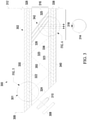
- FIG. 3 illustrates a cross-section view 300 of a PWG 302 that employs this manipulation of polarization state to provide internal reflection of in-coupled display light in accordance with at least one embodiment.
- the PWG 302 represents, for example, the PWG 102 of the system 100 and thus the cross-section view 300 can represent the cross-section A-A illustrated in FIG. 1 . It should be noted that the dimensions of various features depicted in FIG. 3 may be disproportionate to other features for purpose of illustration of principles of operation.
- the PWG 302 extends from one end 306 proximate to a display 308 and in-coupling optic 310 to an opposing end 312 proximate to an expected position 314 of a wearer's eye, and includes an in-coupling interface 316 configured to receive display light from the display 308 via the in-coupling optic 310 and an out-coupling interface 318 to transmit a representation of the display light conveyed by the PWG 302 in an eyeward direction (that is, toward the expected position 314 of the wearer's eye).
- the display 308 can include any of a variety of displays suitable for use in near-eye display systems employing waveguides, such as an organic light emitting diode (OLED) micro-display.
- OLED organic light emitting diode
- the in-coupling optic 310 is disposed between the display 308 and the in-coupling interface 316 and is configured to direct the display light emitted by the display 308 toward the in-coupling interface 316, and in some instances may be configured to collimate the display light in the process.
- the in-coupling optic 310 in some embodiments includes a set of one or more stacked lenses with various lens profiles and configured to impart desired optical manipulations on the display light before entering the PWG 302.
- the PWG 302 includes a waveguide substrate 320 extending from end 306 to end 312.
- the waveguide substrate 320 is composed of a material transparent to the display light, such as glass, optical plastic, and the like.
- the waveguide substrate 320 may instead be a region of air as the PWG 302 does not rely on TIR.
- the waveguide substrate 320 includes two opposing major surfaces 322, 323, with the first major surface 322 being the "eye-facing" surface (that is, the surface facing the wearer's eye) and the second major surface 322 being the "world-facing" surface (that is, the surface facing away from the wearer's eye).
- the surfaces 322, 323 are planar and substantially parallel.
- the opposing major (first and second) surfaces may instead be curved (i.e., non-planar) and/or may be substantially non-parallel to each other, in particular non-parallel to each other (i.e., at a slanted, non-zero, angle relative to each other).
- the waveguide substrate 320 further includes opposing minor surfaces 324, 325.
- the first minor surface 324 is located at end 306 and disposed at an acute angle relative to major surface 323 so as to form the in-coupling interface 316 having an optical axis that is not parallel to the major surfaces 322, 323.
- the in-coupling interface 316 is implemented as a reflective mirror disposed in the waveguide substrate 320.
- the second major surface 325 is located at end 312 and may be disposed perpendicular to the major surfaces 322, 323 as shown, or disposed at a non-perpendicular angle relative to major surfaces 322, 323.
- a first quarter-wave plate (QWP) layer 326 Overlying the major surface 322 is a first quarter-wave plate (QWP) layer 326, along with a first polarization beam splitter (PBS) layer 328 overlying the QWP layer 326 such that the QWP layer 326 is adjacent to the major surface 322 and disposed between the PBS layer 328 and the major surface 322.
- the PWG 302 further may include a linear polarizer (LP) layer 330 overlying the PBS layer 328.
- LP linear polarizer
- a second QWP layer 336 overlies the major surface 323 and a second PBS layer 338 overlies the QWP layer 336 such that the QWP layer 336 is adjacent to the major surface 323 and is disposed between the PBS layer 338 and the major surface 323.
- An LP layer 340 also may be formed overlying the PBS layer 338.
- the QWP layers 326, 336 are implemented using material that operates to convert light having a first circularly polarized state to light having a first linearly polarized state, to convert light having a second circularly polarized state to light having a second linearly polarized state, and to convert light having the first linearly polarized state to the first circularly polarized state. More generally, quarter-wave plates, such as the QWP layers 326, 336, transmit light and modify its polarization state without deviating or displacing the beam. In a quarter-wave plate, the retardation which is the phase difference between the polarization component projected along the fast and slow axis is 1/4 wave.
- the QWP layers 326, 336 may be implemented as, for example multi-order, zero-order, or achromatic QWP layers. Examples of materials implementing the QWP layers 326, 336 include calcite or crystalline films, polychromatic films, and the like.
- the PBS layers 328, 338 are implemented using material that operates to reflect light having the first linearly polarized state and to transmit light having the second linearly polarized state. Examples include wire grid type PBS layers, dielectric coating type PBS layers, and the advanced polarizing film available from 3M (3M APF). Similarly, the LP layers 330, 340 are implemented using material that operates to transmit light having the second linearly polarized state. Examples include a wire grid polarizer, a calcite polarizer, or a dichroic polarizer.
- this polarization-state-based reflection is independent of the critical angle of the QWP layer/PBS layer interface, and thus is not TIR-based reflection.
- the PWG 302 utilizes this particular polarization-state-based reflection property of the QWP layer/PBS layer combination to "bound" display light along the length of the waveguide substrate 320, as described in detail below.
- the PWB 302 employs a light extraction component 342 disposed in the waveguide substrate 320.
- the light extraction component 342 is illustrated as a set of one or more partially-reflective mirrors 344, 345, 346 (e.g., multi-layer films or a dielectric coating) that extend substantially from major surface 322 to major surface 323 at an angle determined to reflect incident light conveyed within the waveguide substrate 320 toward the out-coupling interface 318.
- the light extraction component 342 may be implemented as, for example, a set of Fresnel facets, as described in greater detail below with reference to FIG. 9 .
- the light extraction component 342 is configured to reflect incident light received via the waveguide substrate 320 in the direction of the out-coupling interface 318, which in turn is aligned with the expected position 314 of the wearer's eye. Further, in at least one embodiment, the light extraction component 342 is configured to change the polarization state of the reflected light from the first circularly polarized state to light having the second circularly polarized state. As a result, when the light reflected by the light extraction component 342 encounters the QWP layer 336, the light is converted from the second circularly polarized state to the second linearly polarized state as it propagates through the QWP layer 336.
- the PWG 302 utilizes the circular-polarization state reversal property of the light extraction component 342 to allow the reflected display light to take on the second circularly polarized state that allows the reflected display light to pass through the QWP layer 336, PBS layer 338, and LP layer 340, rather than to continue to be internally reflected within the PWG 302.
- the LP layers 330, 340 operate to reduce the light reflected by the PBS layers 328, 338.
- the LP 340 reduces light that reflects into the user's eye, thereby reducing stray light and ghost images and thus improving image quality.
- the LP layer 330 can reduce the amount of ambient light that is reflected, and thus allow the HMD 100 to work more like a pair of sunglasses.
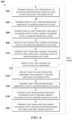
- FIG. 4 illustrates a method 400 of operation of a near-eye display system employing the PWG 302 of FIG. 3 in accordance with at least one embodiment.
- the method 400 initiates at block 402 with the display 308 being operated to emit display light 350 representative of a display image, which may include AR or VR content.
- the in-coupling optic 310 directs the display light 350 into the waveguide substrate 320 of the PWG 302 via the in-coupling interface 316.
- the first circularly polarized state is the right-handed circularly polarized (RCP) state.
- the first circularly polarized state may be the left-handled circularly polarized (LCP) state, with the attendant modifications to the other polarization states described herein.
- RCP right-handed circularly polarized
- LCP left-handled circularly polarized
- the display light 350 propagates through the waveguide substrate 320 at an angle and thus strikes the interface between the waveguide substrate 320 and the QWP layer 326 at a location 351.
- the QWP layer 326 changes the polarization state of the display light to the first linearly polarized state (block 406), which for purposes of example is described herein as a linearly y-polarized state.
- the resulting modified display light 352 then encounters the PBS layer 328 at location 353, and as the PBS layer 328 is configured to reflect light having the first linearly polarized state (linearly y-polarized), the PBS layer 328 reflects modified display light 352 back to the QWP layer 326 (block 408).
- the QWP layer 326 converts the display light from the linear y-polarized state (the first linearly polarized state) back to the RCP state (the first circularly polarized state)(block 410) such that the display light re-enters the waveguide substrate 320 as reflected display light 354 having the original RCP state.
- the reflection of the display light represented by the process of blocks 404-410 repeats one or more times, with each reflection resulting in the display light re-entering the waveguide substrate 320 in the RCP state and at an angle that propagates the display light along the length of the waveguide substrate 320 toward the light extraction component 342.
- the partially-reflective mirrors 344-346 reflect the conveyed display light 361 as reflected display light 362, and in the process of reflecting the display light convert the polarization state from the RCP state (first circularly polarized state) to a left-handed circularly polarized (LCP) state (second circularly polarized state)(block 414).
- the reflected display light 362 is propagated to the portion of the QWP layer 336 corresponding to the out-coupling interface 318 (block 416), and as the reflected display light 362 is transmitted through the QWP layer 336, the QWP layer 336 converts the polarization state of the light from the LCP state (second circularly polarized state) to the linearly x-polarized state (second linearly polarized state)(block 418), resulting in converted display light 363.
- the converted display light 363 is permitted to pass through the PBS layer 338 and LP layer 340 at the region corresponding to the out-coupling interface 318 (block 420) and the emerging converted display light 363 thus propagates from the PWG 302 to the wearer's eye.
- the waveguide substrate 320 may be composed of a material with a lower index of refraction, such as an optical plastic, than the waveguide material typically used in conventional TIR-based waveguides (e.g., relatively heavy and expensive optical glass) to achieve a given FOV.
- a greater FOV may be achieved by the PWG 302 using a material with the same index of refraction as a corresponding TIR-based waveguide.
- the waveguide substrate can employ a non-planar shape or non-parallel major surfaces, which typically is impracticable to implement in a conventional TIR-based waveguide.
- FIG. 7 illustrates an example PWG 702 in which the waveguide substrate 720 includes two opposing planar major surfaces 722, 723 which are substantially non-parallel, that is, at a non-zero angle relative to each other.
- FIG. 8 illustrates an example PWG 802 having a waveguide substrate 820 with opposing major surfaces 822, 823 that are curved (that is, non-planar).
- the major surface 822 is a concave surface and the major surface 823 is a convex surface, thereby forming a convex-concave lens or a meniscus lens.
- the major surfaces 822, 823 may be curved in different orientations, or only one of the major surfaces may be curved, while the other is planar. Further, the curve formed by a surface may be spherical or aspherical.
- the PWG 802 may employ a light extraction component 842 that has curved partially-reflective mirrors to accommodate the curvature of the major surfaces 822, 823.
- the ability to employ curved surfaces in this manner permits the PWG 802 to be implemented in the form factor of eyeglass lenses, such as the PWG 202 implemented in the eyeglass lens 205 in the system 200 of FIG. 2 .
- the ability to introduce curvature of the major surfaces permits the PWG 802 to introduce optical power greater than zero, and thus allowing the PWG 802 to project enlarged imagery than conventional TIR-based waveguides.
- FIGs. 3-8 depict the light extraction component of the PWG as a set of partially reflective mirrors.
- the light extraction component of a PWG is not limited this implementation, but instead may be implemented as any of a variety of optical features that reflect incident light while converting the light from the first circularly polarized state to the second circularly polarized state in the process of reflecting the light.
- FIG. 3-8 depicts the light extraction component of the PWG as a set of partially reflective mirrors.
- the light extraction component of a PWG is not limited this implementation, but instead may be implemented as any of a variety of optical features that reflect incident light while converting the light from the first circularly polarized state to the second circularly polarized state in the process of reflecting the light.
- FIG. 9 illustrates a PWG 902 that employs an in-coupling optic 910 that collimates display light emitted by the display 308 and a light extraction component 942 that includes a set of Fresnel facets 943, 944, 945, 946 disposed at a major surface 923 of a waveguide substrate 920 so as to reflect the conveyed collimated display light toward the opposing major surface 922 of the waveguide substrate 920.
- the Fresnel facets can be fabricated on the world side of the substrate 320, and operate like a prism array with partial mirror coating on it. The function of the Fresnel facets along with the partial mirror is to change the handiness of the circularly polarization and expand the pupil size.
- an apparatus includes: a polarization waveguide including: a waveguide substrate including first and second opposing surfaces; an in-coupling interface proximate to a first end of the polarization waveguide; an out-coupling interface proximate to a second end of the polarization waveguide; a first quarter-wave plate layer overlying the first surface of the waveguide substrate; a first polarization beam splitter layer overlying the first quarter-wave plate layer; a second quarter-wave plate layer overlying the second surface of the waveguide substrate; a second polarization beam splitter layer overlying the second quarter-wave plate layer; and a light extraction component configured to reflect incident light received in the waveguide substrate toward the out-coupling interface.
- the light extraction component incldes a set of one or more partially-reflective mirrors extending substantially between the first and second surfaces of the waveguide substrate in a region of the waveguide substrate aligned with the out-coupling interface.
- the out-coupling interface is adjacent to the first surface of the waveguide substrate; and the light extraction component includes a set of Fresnel facets disposed adjacent to the second surface of the waveguide substrate and aligned with the out-coupling interface.
- the apparatus includes a display configured to emit display light representative of an image; and an in-coupling optic disposed between the display and the in-coupling interface, the in-coupling optic configured to direct the display light toward the in-coupling interface.
- the display is configured to emit the display light having a first circularly polarized state;
- the first quarter-wave plate layer and the second quarter-wave plate layer each is configured to convert incident light having first circularly polarized state to light having a first linearly polarized state, to convert incident light having the first linearly polarized state to light having the first circularly polarized state, and to convert incident light having a second circularly polarized state to a second linearly polarized state;
- the first polarization beam splitter layer and the second polarization beam splitter layer each is configured to reflect light having the first linearly polarized state and to transmit light having the second linearly polarized state;
- the light extraction component is configured to change reflected light from the first circularly polarized state to the second circularly polarized state.
- first surface and second surface are substantially parallel. In another aspect the first surface and the second surface are substantially non-parallel. In still another aspect at least one of the first surface and the second surface is a curved surface. In another aspect the first surface is a convex surface; and the second surface is a concave surface.
- the curved surface is one of: a spherical curved surface or an aspherical curved surface.
- the polarization waveguide has a non-zero optical power.
- the apparatus includes a first linear polarization layer overlying the first polarization beam splitter layer; and a second linear polarization layer overlying the second polarization beam splitter layer.
- the apparatus includes an eyeglass frame including an eyeglass lens; and wherein the polarization waveguide overlies the eyeglass lens with the eyeglass lens disposed between the out-coupling interface of the polarization waveguide and an expected position of a corresponding eye of a wearer of the eyeglass frame.
- the apparatus includes an eyeglass frame including an eyeglass lens; and wherein the eyeglass lens implements the polarization waveguide and the out-coupling interface is disposed at or adjacent to an eyeward surface of the eyeglass lens.
- a method includes: providing a polarization waveguide including an in-coupling interface proximate to one end and an out-coupling interface proximate to an opposite end, a waveguide substrate having first and second opposing surfaces, a first quarter-wave plate layer overlying the first surface, a first polarization beam splitter layer overlying the first quarter-wave plate layer, a second quarter-wave plate layer overlying the second surface, and a second polarization beam splitter layer overlying the second quarter-wave plate layer, and a light extraction component to reflect incident light received in the waveguide substrate toward an out-coupling interface of the polarization waveguide; directing display light emitted by a display to the in-coupling interface; conveying a representation of the display light through the polarization waveguide from the in-coupling interface to the out-coupling interface; and transmitting the representation of the display light eyeward from the out-coupling interface.
- conveying the representation of the display light through the polarization waveguide includes reflecting light within the polarization waveguide at an angle less than a critical angle of an interface between two materials of the polarization waveguide at a point of reflection.
- conveying the representation of the display light includes: receiving the display light having a first circularly polarized state at the in-coupling interface; converting the display light from the first circularly polarized state to a first linearly polarized state at the first quarter-wave plate layer; reflecting the display light having the first linearly polarized state at the first polarization beam splitter layer; and converting the reflected display light from the first linearly polarized state back to the first circularly polarized state at the first quarter-wave plate layer.
- conveying the representation of the display light further includes: reflecting, at the light extraction component, a reflected representation of the display light in a direction of the out-coupling interface, wherein reflecting the reflected representation of the display light converts the reflected representation of the display light from the first circularly polarized state to a second circularly polarized state; converting the reflected representation of the display light from the second circularly polarized state to a second linearly polarized state at the second quarter-wave plate layer; and transmitting the reflected representation of the display light having the second linearly polarized state in an eyeward direction through the second polarization beam splitter layer.
- a near-eye display system includes: a polarization waveguide having an in-coupling interface disposed proximate to a first end and an out-coupling interface disposed proximate to an opposite second end, the polarization waveguide configured to convey light incident at the in-coupling interface to the out-coupling interface by inducing multiple changes in a polarization state of the light as the light traverses the polarization waveguide, wherein at least a portion of the changes in polarization state induce the light to reflect within the polarization waveguide.
- the system includes a display proximate to the first end, the display configured to emit light representative of an image; and an in-coupling optic disposed between the display and the in-coupling interface, the in-coupling optic configured to direct the light from the display to the in-coupling interface.
- the system includes an eyeglass frame having an eyeglass lens; and wherein the polarization waveguide is implemented in the eyeglass lens.
- the system includes an eyeglass frame having an eyeglass lens; and wherein the polarization waveguide overlies the eyeglass lens.
- the system includes on each surface of a pair of opposing surfaces of a waveguide substrate: a first layer overlying the waveguide substrate and configured to change incident light having a first circularly polarized state to light having a first linearly polarized state, to change incident light having the first linearly polarized state to light having the first circularly polarized state, and to change incident light having a second circularly polarized state to light having a second linearly polarized state; and a second layer overlying the first layer and configured to reflect incident light having the first linearly polarized state and to transmit incident light having the second linearly polarized state; and a light extraction component disposed within the waveguide substrate and configured to reflect incident light in a direction toward the out-coupling interface and to change a polarization state of the reflected light from the first circularly polarized state to the second circularly polarized state.
Landscapes
- Physics & Mathematics (AREA)
- General Physics & Mathematics (AREA)
- Optics & Photonics (AREA)
- Polarising Elements (AREA)
Abstract
Description
- Near-eye display systems typically employ a waveguide (also frequently referred to as a "lightguide") to convey light emitted by a display to a user's eye. In conventional implementations, the waveguide relies on total internal reflection (TIR) to convey light received from the display via in-coupling optics at one end of the waveguide to out-coupling optics facing the user's eye on the other end of the waveguide. To achieve TIR, such waveguides must be composed of material with a high index of refraction. However, implementation of such materials can be problematic. For one, the field of view (FOV) provided by a conventional TIR-based waveguide is inversely proportional to the index of refraction of the material of the waveguide, and thus the high index of refraction needed to achieve TIR impedes the FOV that can be provided by the waveguide, which typically is no more than 50 degrees. Moreover, waveguide materials with higher indices of refraction tend to be both heavier and more expensive than materials with lower indexes of refraction, and consequently conventional TIR-based waveguides tend to be more expensive and heavier. Additionally, systems employing TIR-based waveguides often must be sealed in order to reduce the risk of contamination of the surface of the waveguide, which can break the TIR condition and lead to light leakage. The mechanisms used to provide this seal often increase the cost, weight, and complexity of the system and are prone to failure.
- The present disclosure may be better understood, and its numerous features and advantages made apparent to those skilled in the art by referencing the accompanying drawings. The use of the same reference symbols in different drawings indicates similar or identical items.
-
FIG. 1 is a front view of an example form factor for a near-eye display system employing a polarization waveguide in accordance with some embodiments. -
FIG. 2 is a perspective view of another example form factor for a near-eye display system employing a polarization waveguide in accordance with some embodiments. -
FIG. 3 is a cross-section view of a polarization waveguide with associated display and in-coupling optic in accordance with some embodiments. -
FIG. 4 is a flow diagram illustrating a method of employing a near-eye display system with a polarization waveguide to display imagery to a user in accordance with some embodiments. -
FIG. 5 is an enlarged view of a portion of the cross-section view of the polarization waveguide ofFIG. 3 illustrating an operation of an interface between a quarter-wave plate layer and a polarization beam splitter layer of the polarization waveguide in accordance with some embodiments. -
FIG. 6 is an enlarged view of another portion of the cross-section view of the polarization waveguide ofFIG. 3 illustrating an operation of interfaces between a light-extraction component, a quarter-wave plate layer, and a polarization beam splitter layer of the polarization waveguide in accordance with some embodiments. -
FIG. 7 is a cross-section view of another embodiment of a polarization waveguide having non-parallel, or slanted, opposing surfaces in accordance with some embodiments of the present disclosure. -
FIG. 8 is a cross-section view of another embodiment of a polarization waveguide having curved opposing surfaces in accordance with some embodiments of the present disclosure. -
FIG. 9 is a cross-section view of another embodiment of a polarization waveguide utilizing another example of a light extraction component with some embodiments of the present disclosure. -
FIGs. 1-9 illustrate example implementations of a polarization waveguide for use in a near-eye display system. The near-eye display system uses the polarization waveguide (PWG) to convey light representative of display images from a micro-display or other display to a wearer's eye. However, unlike conventional waveguides that rely on total internal reflection (TIR) to convey light in such a manner, and with the attendant trade-offs, the PWG does not rely on TIR, but instead conveys a representation of the display light from an in-coupling interface facing the display to an out-coupling interface facing an eye through multiple changes of the polarization state of the representative light as it traverses the polarization waveguide, where at least a subset of these changes in the polarization state induce reflection of the representative light within the PWG. The changes in polarization state of the representative light from receipt of the display light at the in-coupling interface to a light extraction component of the polarization waveguide are implemented so as to facilitate reflection of the representative light due to its particular polarization state at a corresponding layer interface of the PWG. When the reflected light reaches the light extraction component, the light extraction component reflects the light toward the out-coupling interface, and in doing so changes the polarization state of the reflected light so as to permit the reflect light to traverse the layers of the PWG that served to reflect the light when the conveyed light was in other polarization states, and thus allowing the reflected light ultimately to emerge from the PWG at the out-coupling interface in an eyeward direction. - By manipulating the polarization state of the display light to enable reflection of the display light within the PWG until it is ultimately redirected eyeward, the PWG is able to convey the display light from the in-coupling interface to the out-coupling interface in a manner that is not reliant on total internal reflection (TIR), in contrast to conventional near-eye waveguides. As such, the waveguide substrate of the PWG which serves as the primary conduit for the display light between in-coupling and out-coupling can be implemented using optically transparent material with a lower index of refraction than the waveguide material used in conventional TIR-based waveguides, while also providing a higher FOV than such conventional waveguides for a material with a given index of refraction. Consequently, the PWG may be lighter and less expensive to manufacture. Moreover, because TIR is not necessary, the PWG may be implemented in a form factor that has non-parallel major surfaces or is non-planar. As an example, the PWG could be implemented in a form factor with one or both major surfaces being curved surfaces, and as such can be implemented to provide a non-zero optical power or implemented within an eyeglass lens fitted to an eyeglass frame.
-
FIG. 1 illustrates an example near-eye display system 100 employing a polarization waveguide (PWG) 102 in accordance with at least one embodiment. Thesystem 100 is implemented in an eyeglass form factor having aneyeglass frame 104 witheyeglass lenses eyeglass lens 105 in this instance) such that an out-coupling interface (described in greater detail below with reference toFIG. 3 ) of thePWG 102 faces the expected position of the corresponding eye of the wearer. The PWG 102 is mounted to theeyeglass frame 104 via a waveguide mount housing 109, which also serves to house some or all of the electronic components (not illustrated inFIG. 1 ) of the near-eye display system 100, such as a display that generates augmented reality (AR) or (VR) imagery for display to the wearer via thePWG 102, an in-coupling optic to direct light from the display to an in-coupling interface of thePWG 102, one or more processors, wireless interfaces, batteries or other power sources, and the like. A number of these components are described in greater detail below. -
FIG. 2 illustrates another example near-eye display system 200 employing aPWG 202 in accordance with at least one embodiment. As with thesystem 100 ofFIG. 1 , thesystem 200 employs an eyeglass form factor with aneyeglass frame 204 havingeyeglass lenses system 100, thesystem 200 implements the PWG 202 using theeyeglass lens 205. That is, the PWG 202 is integrated within theeyeglass lens 205, and thus allowing the near-eye display system 200 to have a more traditional eyeglass appearance. In this implementation, a display housing (omitted fromFIG. 2 for clarity of illustration) on theeyeglass frame 204 at the distal periphery of theeyeglass lens 205 contains a micro-display or other display to emit display light representative of AR or VR imagery and in-coupling optic to direct the emitted display light to an in-coupling interface of thePWG 202 in thelens 205, whereupon the display light is propagated through thePWG 202/eyeglass lens 205 toward an out-coupling interface 207 that is located in theeyeglass lens 205/PWG 202 so as to be aligned with an expected position (or expected range of positions) of a corresponding eye of the wearer. In some embodiments, theeyeglass lens 206 likewise implements a corresponding PWG and thesystem 200 employs corresponding display componentry in the same manner to provide for the display of AR or VR imagery to the other eye of the wearer as well. - The PWG 102 of
system 100 ofFIG. 1 and the PWG 202 ofsystem 200 ofFIG. 2 each operates to convey display light from a proximate display to an eye of the user via multiple reflections of the display light within the body of the PWG as the display light traverses from one end of the PWG proximate to the display to the opposing end of the PWG facing an eye of the wearer. However, unlike a conventional waveguide, these reflections do not rely on TIR; that is, the angle of incidence may be less than the critical angle of the interface between mediums at the point of reflection. Rather than relying on TIR, the PWG instead manipulates the polarization state of the display light as it propagates through the PWG so as to cause the display light to reflect one or more times within the PWG until a light extraction feature is encountered, at which point the polarization state of the display light is changed in a manner that permits the display light to transmit through the surface of the PWG at an out-coupling interface that faces the wearer's eye. -
FIG. 3 illustrates across-section view 300 of aPWG 302 that employs this manipulation of polarization state to provide internal reflection of in-coupled display light in accordance with at least one embodiment. ThePWG 302 represents, for example, thePWG 102 of thesystem 100 and thus thecross-section view 300 can represent the cross-section A-A illustrated inFIG. 1 . It should be noted that the dimensions of various features depicted inFIG. 3 may be disproportionate to other features for purpose of illustration of principles of operation. - The PWG 302 extends from one
end 306 proximate to adisplay 308 and in-coupling optic 310 to anopposing end 312 proximate to an expectedposition 314 of a wearer's eye, and includes an in-coupling interface 316 configured to receive display light from thedisplay 308 via the in-coupling optic 310 and an out-coupling interface 318 to transmit a representation of the display light conveyed by the PWG 302 in an eyeward direction (that is, toward the expectedposition 314 of the wearer's eye). Thedisplay 308 can include any of a variety of displays suitable for use in near-eye display systems employing waveguides, such as an organic light emitting diode (OLED) micro-display. The in-coupling optic 310 is disposed between thedisplay 308 and the in-coupling interface 316 and is configured to direct the display light emitted by thedisplay 308 toward the in-coupling interface 316, and in some instances may be configured to collimate the display light in the process. Although depicted as a single bi-convex lens for ease of illustration, the in-coupling optic 310 in some embodiments includes a set of one or more stacked lenses with various lens profiles and configured to impart desired optical manipulations on the display light before entering thePWG 302. - In at least one embodiment, the PWG 302 includes a
waveguide substrate 320 extending fromend 306 toend 312. Thewaveguide substrate 320 is composed of a material transparent to the display light, such as glass, optical plastic, and the like. In some embodiments, thewaveguide substrate 320 may instead be a region of air as the PWG 302 does not rely on TIR. Thewaveguide substrate 320 includes two opposingmajor surfaces major surface 322 being the "eye-facing" surface (that is, the surface facing the wearer's eye) and the secondmajor surface 322 being the "world-facing" surface (that is, the surface facing away from the wearer's eye). In the example ofFIG. 3 , thesurfaces FIGs. 7-9 , because the PWG does not rely on TIR, the opposing major (first and second) surfaces may instead be curved (i.e., non-planar) and/or may be substantially non-parallel to each other, in particular non-parallel to each other (i.e., at a slanted, non-zero, angle relative to each other). Thewaveguide substrate 320 further includes opposingminor surfaces minor surface 324 is located atend 306 and disposed at an acute angle relative tomajor surface 323 so as to form the in-coupling interface 316 having an optical axis that is not parallel to themajor surfaces coupling interface 316 is implemented as a reflective mirror disposed in thewaveguide substrate 320. The secondmajor surface 325 is located atend 312 and may be disposed perpendicular to themajor surfaces major surfaces - Overlying the
major surface 322 is a first quarter-wave plate (QWP)layer 326, along with a first polarization beam splitter (PBS)layer 328 overlying theQWP layer 326 such that theQWP layer 326 is adjacent to themajor surface 322 and disposed between thePBS layer 328 and themajor surface 322. The PWG 302 further may include a linear polarizer (LP)layer 330 overlying thePBS layer 328. Similarly, asecond QWP layer 336 overlies themajor surface 323 and asecond PBS layer 338 overlies theQWP layer 336 such that theQWP layer 336 is adjacent to themajor surface 323 and is disposed between thePBS layer 338 and themajor surface 323. AnLP layer 340 also may be formed overlying thePBS layer 338. - The QWP layers 326, 336 (also known as "retarders") are implemented using material that operates to convert light having a first circularly polarized state to light having a first linearly polarized state, to convert light having a second circularly polarized state to light having a second linearly polarized state, and to convert light having the first linearly polarized state to the first circularly polarized state. More generally, quarter-wave plates, such as the QWP layers 326, 336, transmit light and modify its polarization state without deviating or displacing the beam. In a quarter-wave plate, the retardation which is the phase difference between the polarization component projected along the fast and slow axis is 1/4 wave. The QWP layers 326, 336 may be implemented as, for example multi-order, zero-order, or achromatic QWP layers. Examples of materials implementing the QWP layers 326, 336 include calcite or crystalline films, polychromatic films, and the like.
- The PBS layers 328, 338 are implemented using material that operates to reflect light having the first linearly polarized state and to transmit light having the second linearly polarized state. Examples include wire grid type PBS layers, dielectric coating type PBS layers, and the advanced polarizing film available from 3M (3M APF). Similarly, the LP layers 330, 340 are implemented using material that operates to transmit light having the second linearly polarized state. Examples include a wire grid polarizer, a calcite polarizer, or a dichroic polarizer.
- With the described configuration, light propagating within the
waveguide substrate 320 and having the first circularly polarized state that is incident on one of the QWP layers is converted to light having the first linearly polarized state as it propagates through the QWP layer. This converted light with the first linearly polarized state then encounters the overlying PBS layer, which is configured to reflect light having the first linearly polarized state, and thus reflects the light back through the underlying QWP layer. As this light propagates through the QWP layer, the QWP layer converts the polarization state of the light from the first linearly polarized state to the first circularly polarized state, such that the reflected light re-enters thewaveguide substrate 320 having the first circularly polarized state. It will be appreciated that this polarization-state-based reflection is independent of the critical angle of the QWP layer/PBS layer interface, and thus is not TIR-based reflection. ThePWG 302 utilizes this particular polarization-state-based reflection property of the QWP layer/PBS layer combination to "bound" display light along the length of thewaveguide substrate 320, as described in detail below. - To facilitate transmission of reflected display light conveyed by the
PWG 302 toward the wearer's eye, thePWB 302 employs alight extraction component 342 disposed in thewaveguide substrate 320. In the embodiment ofFIG. 3 , thelight extraction component 342 is illustrated as a set of one or more partially-reflective mirrors major surface 322 tomajor surface 323 at an angle determined to reflect incident light conveyed within thewaveguide substrate 320 toward the out-coupling interface 318. In other embodiments, thelight extraction component 342 may be implemented as, for example, a set of Fresnel facets, as described in greater detail below with reference toFIG. 9 . - The
light extraction component 342 is configured to reflect incident light received via thewaveguide substrate 320 in the direction of the out-coupling interface 318, which in turn is aligned with the expectedposition 314 of the wearer's eye. Further, in at least one embodiment, thelight extraction component 342 is configured to change the polarization state of the reflected light from the first circularly polarized state to light having the second circularly polarized state. As a result, when the light reflected by thelight extraction component 342 encounters theQWP layer 336, the light is converted from the second circularly polarized state to the second linearly polarized state as it propagates through theQWP layer 336. As thePBS layer 338 andLP layer 340 are configured to transmit light having the second linearly polarized state, the light emerging from theQWP layer 336 is then permitted to pass through thePBS layer 338 andLP layer 340 and propagate to the wearer's eye. As such, thePWG 302 utilizes the circular-polarization state reversal property of thelight extraction component 342 to allow the reflected display light to take on the second circularly polarized state that allows the reflected display light to pass through theQWP layer 336,PBS layer 338, andLP layer 340, rather than to continue to be internally reflected within thePWG 302. - The LP layers 330, 340 operate to reduce the light reflected by the PBS layers 328, 338. On the eye-ward side, the
LP 340 reduces light that reflects into the user's eye, thereby reducing stray light and ghost images and thus improving image quality. On the world-facing side, theLP layer 330 can reduce the amount of ambient light that is reflected, and thus allow theHMD 100 to work more like a pair of sunglasses. -
FIG. 4 illustrates amethod 400 of operation of a near-eye display system employing thePWG 302 ofFIG. 3 in accordance with at least one embodiment. Themethod 400 initiates atblock 402 with thedisplay 308 being operated to emitdisplay light 350 representative of a display image, which may include AR or VR content. The in-coupling optic 310 directs thedisplay light 350 into thewaveguide substrate 320 of thePWG 302 via the in-coupling interface 316. For purposes of illustration, the first circularly polarized state is the right-handed circularly polarized (RCP) state. However, in other embodiments, the first circularly polarized state may be the left-handled circularly polarized (LCP) state, with the attendant modifications to the other polarization states described herein. - As illustrated by
enlarged inset view 301 ofFIG. 5 , atblock 404, thedisplay light 350 propagates through thewaveguide substrate 320 at an angle and thus strikes the interface between thewaveguide substrate 320 and theQWP layer 326 at alocation 351. As the display light propagates through theQWP layer 326, theQWP layer 326 changes the polarization state of the display light to the first linearly polarized state (block 406), which for purposes of example is described herein as a linearly y-polarized state. The resulting modifieddisplay light 352 then encounters thePBS layer 328 atlocation 353, and as thePBS layer 328 is configured to reflect light having the first linearly polarized state (linearly y-polarized), thePBS layer 328 reflects modifieddisplay light 352 back to the QWP layer 326 (block 408). As the reflecteddisplay light 352 propagates through theQWP layer 326, theQWP layer 326 converts the display light from the linear y-polarized state (the first linearly polarized state) back to the RCP state (the first circularly polarized state)(block 410) such that the display light re-enters thewaveguide substrate 320 as reflecteddisplay light 354 having the original RCP state. - As represented by
block 412 ofmethod 400, the reflection of the display light represented by the process of blocks 404-410 repeats one or more times, with each reflection resulting in the display light re-entering thewaveguide substrate 320 in the RCP state and at an angle that propagates the display light along the length of thewaveguide substrate 320 toward thelight extraction component 342. As illustrated byenlarged inset view 303 ofFIG. 6 , when conveyeddisplay light 361 falls incident on the partially-reflective mirrors 344-346 of thelight extraction component 342, the partially-reflective mirrors 344-346 reflect the conveyeddisplay light 361 as reflecteddisplay light 362, and in the process of reflecting the display light convert the polarization state from the RCP state (first circularly polarized state) to a left-handed circularly polarized (LCP) state (second circularly polarized state)(block 414). The reflecteddisplay light 362 is propagated to the portion of theQWP layer 336 corresponding to the out-coupling interface 318 (block 416), and as the reflecteddisplay light 362 is transmitted through theQWP layer 336, theQWP layer 336 converts the polarization state of the light from the LCP state (second circularly polarized state) to the linearly x-polarized state (second linearly polarized state)(block 418), resulting in converteddisplay light 363. As thePBS layer 338 andLP layer 340 each is configured to transmit light having the linearly x-polarized state, the converteddisplay light 363 is permitted to pass through thePBS layer 338 andLP layer 340 at the region corresponding to the out-coupling interface 318 (block 420) and the emerging converteddisplay light 363 thus propagates from thePWG 302 to the wearer's eye. - The internal reflections within the
PWG 302 represented by blocks 404-412 result from manipulation of the polarization state of the conveyed light in view of the polarization-state-specific reflection and transmission properties of the stack of material layers overlying themajor surfaces waveguide substrate 320, and do not rely on TIR. Thus, thewaveguide substrate 320 may be composed of a material with a lower index of refraction, such as an optical plastic, than the waveguide material typically used in conventional TIR-based waveguides (e.g., relatively heavy and expensive optical glass) to achieve a given FOV. Alternatively, a greater FOV may be achieved by thePWG 302 using a material with the same index of refraction as a corresponding TIR-based waveguide. Moreover, because TIR is not required, the waveguide substrate can employ a non-planar shape or non-parallel major surfaces, which typically is impracticable to implement in a conventional TIR-based waveguide. - To illustrate,
FIG. 7 illustrates anexample PWG 702 in which thewaveguide substrate 720 includes two opposing planarmajor surfaces 722, 723 which are substantially non-parallel, that is, at a non-zero angle relative to each other. Further,FIG. 8 illustrates anexample PWG 802 having awaveguide substrate 820 with opposingmajor surfaces major surface 822 is a concave surface and themajor surface 823 is a convex surface, thereby forming a convex-concave lens or a meniscus lens. In other embodiments, themajor surfaces PWG 802 may employ alight extraction component 842 that has curved partially-reflective mirrors to accommodate the curvature of themajor surfaces PWG 802 to be implemented in the form factor of eyeglass lenses, such as thePWG 202 implemented in theeyeglass lens 205 in thesystem 200 ofFIG. 2 . Moreover, the ability to introduce curvature of the major surfaces permits thePWG 802 to introduce optical power greater than zero, and thus allowing thePWG 802 to project enlarged imagery than conventional TIR-based waveguides. - The PWG implementations of
FIGs. 3-8 depict the light extraction component of the PWG as a set of partially reflective mirrors. However, the light extraction component of a PWG is not limited this implementation, but instead may be implemented as any of a variety of optical features that reflect incident light while converting the light from the first circularly polarized state to the second circularly polarized state in the process of reflecting the light. To illustrate,FIG. 9 illustrates aPWG 902 that employs an in-coupling optic 910 that collimates display light emitted by thedisplay 308 and alight extraction component 942 that includes a set ofFresnel facets major surface 923 of awaveguide substrate 920 so as to reflect the conveyed collimated display light toward the opposingmajor surface 922 of thewaveguide substrate 920. The Fresnel facets can be fabricated on the world side of thesubstrate 320, and operate like a prism array with partial mirror coating on it. The function of the Fresnel facets along with the partial mirror is to change the handiness of the circularly polarization and expand the pupil size. - As disclosed herein, in some embodiments an apparatus includes: a polarization waveguide including: a waveguide substrate including first and second opposing surfaces; an in-coupling interface proximate to a first end of the polarization waveguide; an out-coupling interface proximate to a second end of the polarization waveguide; a first quarter-wave plate layer overlying the first surface of the waveguide substrate; a first polarization beam splitter layer overlying the first quarter-wave plate layer; a second quarter-wave plate layer overlying the second surface of the waveguide substrate; a second polarization beam splitter layer overlying the second quarter-wave plate layer; and a light extraction component configured to reflect incident light received in the waveguide substrate toward the out-coupling interface.
- In one aspect the light extraction component incldes a set of one or more partially-reflective mirrors extending substantially between the first and second surfaces of the waveguide substrate in a region of the waveguide substrate aligned with the out-coupling interface. In another aspect the out-coupling interface is adjacent to the first surface of the waveguide substrate; and the light extraction component includes a set of Fresnel facets disposed adjacent to the second surface of the waveguide substrate and aligned with the out-coupling interface. In one aspect the apparatus includes a display configured to emit display light representative of an image; and an in-coupling optic disposed between the display and the in-coupling interface, the in-coupling optic configured to direct the display light toward the in-coupling interface.
- In another aspect the display is configured to emit the display light having a first circularly polarized state; the first quarter-wave plate layer and the second quarter-wave plate layer each is configured to convert incident light having first circularly polarized state to light having a first linearly polarized state, to convert incident light having the first linearly polarized state to light having the first circularly polarized state, and to convert incident light having a second circularly polarized state to a second linearly polarized state; the first polarization beam splitter layer and the second polarization beam splitter layer each is configured to reflect light having the first linearly polarized state and to transmit light having the second linearly polarized state; and the light extraction component is configured to change reflected light from the first circularly polarized state to the second circularly polarized state. In one aspect the first surface and second surface are substantially parallel. In another aspect the first surface and the second surface are substantially non-parallel. In still another aspect at least one of the first surface and the second surface is a curved surface. In another aspect the first surface is a convex surface; and the second surface is a concave surface.
- In one aspect the curved surface is one of: a spherical curved surface or an aspherical curved surface. In another aspect, the polarization waveguide has a non-zero optical power. In another aspect, the apparatus includes a first linear polarization layer overlying the first polarization beam splitter layer; and a second linear polarization layer overlying the second polarization beam splitter layer. In still another aspect, the apparatus includes an eyeglass frame including an eyeglass lens; and wherein the polarization waveguide overlies the eyeglass lens with the eyeglass lens disposed between the out-coupling interface of the polarization waveguide and an expected position of a corresponding eye of a wearer of the eyeglass frame. In one aspect, the apparatus includes an eyeglass frame including an eyeglass lens; and wherein the eyeglass lens implements the polarization waveguide and the out-coupling interface is disposed at or adjacent to an eyeward surface of the eyeglass lens.
- In some embodiments, a method includes: providing a polarization waveguide including an in-coupling interface proximate to one end and an out-coupling interface proximate to an opposite end, a waveguide substrate having first and second opposing surfaces, a first quarter-wave plate layer overlying the first surface, a first polarization beam splitter layer overlying the first quarter-wave plate layer, a second quarter-wave plate layer overlying the second surface, and a second polarization beam splitter layer overlying the second quarter-wave plate layer, and a light extraction component to reflect incident light received in the waveguide substrate toward an out-coupling interface of the polarization waveguide; directing display light emitted by a display to the in-coupling interface; conveying a representation of the display light through the polarization waveguide from the in-coupling interface to the out-coupling interface; and transmitting the representation of the display light eyeward from the out-coupling interface. In another aspect, conveying the representation of the display light through the polarization waveguide includes reflecting light within the polarization waveguide at an angle less than a critical angle of an interface between two materials of the polarization waveguide at a point of reflection. In still another aspect, conveying the representation of the display light includes: receiving the display light having a first circularly polarized state at the in-coupling interface; converting the display light from the first circularly polarized state to a first linearly polarized state at the first quarter-wave plate layer; reflecting the display light having the first linearly polarized state at the first polarization beam splitter layer; and converting the reflected display light from the first linearly polarized state back to the first circularly polarized state at the first quarter-wave plate layer.
- In another aspect conveying the representation of the display light further includes: reflecting, at the light extraction component, a reflected representation of the display light in a direction of the out-coupling interface, wherein reflecting the reflected representation of the display light converts the reflected representation of the display light from the first circularly polarized state to a second circularly polarized state; converting the reflected representation of the display light from the second circularly polarized state to a second linearly polarized state at the second quarter-wave plate layer; and transmitting the reflected representation of the display light having the second linearly polarized state in an eyeward direction through the second polarization beam splitter layer.
- In some embodiments, a near-eye display system includes: a polarization waveguide having an in-coupling interface disposed proximate to a first end and an out-coupling interface disposed proximate to an opposite second end, the polarization waveguide configured to convey light incident at the in-coupling interface to the out-coupling interface by inducing multiple changes in a polarization state of the light as the light traverses the polarization waveguide, wherein at least a portion of the changes in polarization state induce the light to reflect within the polarization waveguide. In one aspect, the system includes a display proximate to the first end, the display configured to emit light representative of an image; and an in-coupling optic disposed between the display and the in-coupling interface, the in-coupling optic configured to direct the light from the display to the in-coupling interface. In another aspect, the system includes an eyeglass frame having an eyeglass lens; and wherein the polarization waveguide is implemented in the eyeglass lens. In still another aspect the system includes an eyeglass frame having an eyeglass lens; and wherein the polarization waveguide overlies the eyeglass lens.
- 24. In one aspect, the system includes on each surface of a pair of opposing surfaces of a waveguide substrate: a first layer overlying the waveguide substrate and configured to change incident light having a first circularly polarized state to light having a first linearly polarized state, to change incident light having the first linearly polarized state to light having the first circularly polarized state, and to change incident light having a second circularly polarized state to light having a second linearly polarized state; and a second layer overlying the first layer and configured to reflect incident light having the first linearly polarized state and to transmit incident light having the second linearly polarized state; and a light extraction component disposed within the waveguide substrate and configured to reflect incident light in a direction toward the out-coupling interface and to change a polarization state of the reflected light from the first circularly polarized state to the second circularly polarized state.
- Note that not all of the activities or elements described above in the general description are required, that a portion of a specific activity or device may not be required, and that one or more further activities may be performed, or elements included, in addition to those described. Still further, the order in which activities are listed are not necessarily the order in which they are performed. Also, the concepts have been described with reference to specific embodiments. However, one of ordinary skill in the art appreciates that various modifications and changes can be made without departing from the scope of the present disclosure as set forth in the claims below. Accordingly, the specification and figures are to be regarded in an illustrative rather than a restrictive sense, and all such modifications are intended to be included within the scope of the present disclosure.
- Benefits, other advantages, and solutions to problems have been described above with regard to specific embodiments. However, the benefits, advantages, solutions to problems, and any feature(s) that may cause any benefit, advantage, or solution to occur or become more pronounced are not to be construed as a critical, required, or essential feature of any or all the claims. Moreover, the particular embodiments disclosed above are illustrative only, as the disclosed subject matter may be modified and practiced in different but equivalent manners apparent to those skilled in the art having the benefit of the teachings herein. No limitations are intended to the details of construction or design herein shown, other than as described in the claims below. It is therefore evident that the particular embodiments disclosed above may be altered or modified and all such variations are considered within the scope of the disclosed subject matter. Accordingly, the protection sought herein is as set forth in the claims below.
- The proposed solution in particular includes to the following embodiments:
- Embodiment 1: An apparatus comprising:
a polarization waveguide [102] comprising:- a waveguide substrate [320] comprising first [322] and second [323] opposing surfaces;
- an in-coupling interface [316] proximate to a first end of the polarization waveguide;
- an out-coupling interface [318] proximate to a second end of the polarization waveguide;
- a first quarter-wave plate layer [326] overlying the first surface of the waveguide substrate;
- a first polarization beam splitter layer [328] overlying the first quarter-wave plate layer;
- a second quarter-wave plate layer [336] overlying the second surface of the waveguide substrate;
- a second polarization beam splitter layer [338] overlying the second quarter-wave plate layer; and
- a light extraction component [442] configured to reflect incident light received in the waveguide substrate toward the out-coupling interface.
- Embodiment 2: The apparatus of Embodiment 1, wherein:
the light extraction component comprises a set of one or more partially-reflective mirrors [444, 445, 446] extending substantially between the first and second surfaces of the waveguide substrate in a region of the waveguide substrate aligned with the out-coupling interface. - Embodiment 3: The apparatus of Embodiment 1 or 2, wherein:
- the out-coupling interface is adjacent to the first surface of the waveguide substrate; and
- the light extraction component comprises a set of Fresnel facets disposed adjacent to the second surface of the waveguide substrate and aligned with the out-coupling interface.
- Embodiment 4: The apparatus of any one of Embodiments 1 to 3, further comprising:
- a display [308] configured to emit display light representative of an image; and
- an in-coupling optic [310] disposed between the display and the in-coupling interface, the in-coupling optic configured to direct the display light toward the in-coupling interface.
- Embodiment 5: The apparatus of Embodiment 4, wherein:
- the display is configured to emit the display light having a first circularly polarized state;
- the first quarter-wave plate layer and the second quarter-wave plate layer each is configured to convert incident light having first circularly polarized state to light having a first linearly polarized state, to convert incident light having the first linearly polarized state to light having the first circularly polarized state, and to convert incident light having a second circularly polarized state to a second linearly polarized state;
- the first polarization beam splitter layer and the second polarization beam splitter layer each is configured to reflect light having the first linearly polarized state and to transmit light having the second linearly polarized state; and
- the light extraction component is configured to change reflected light from the first circularly polarized state to the second circularly polarized state.
- Embodiment 6: The apparatus of any one of Embodiments 1 to 5, wherein:
the first surface and second surface are substantially parallel. - Embodiment 7: The apparatus of any one of Embodiments 1 to 5, wherein:
the first surface and the second surface are substantially non-parallel. - Embodiment 8: The apparatus of any one of Embodiments 1 to 7, wherein:
at least one of the first surface and the second surface is a curved surface. - Embodiment 9: The apparatus of Embodiment 8, wherein:
- the first surface is a convex surface; and
- the second surface is a concave surface.
- Embodiment 10: The apparatus of Embodiment 8, wherein:
the curved surface is one of: a spherical curved surface or an aspherical curved surface. - Embodiment 11: The apparatus of any one of Embodiments 8 to 10, wherein:
the polarization waveguide has a non-zero optical power. - Embodiment 12: The apparatus of any one of Embodiments 1 to 11, further comprising:
- a first linear polarization layer overlying the first polarization beam splitter layer; and
- a second linear polarization layer overlying the second polarization beam splitter layer.
- Embodiment 13: The apparatus of any one of Embodiments 1 to 12, further comprising:
- an eyeglass frame [105] comprising an eyeglass lens [104, 106]; and
- wherein the polarization waveguide overlies the eyeglass lens with the eyeglass lens disposed between the out-coupling interface of the polarization waveguide and an expected position of a corresponding eye of a wearer of the eyeglass frame.
- Embodiment 14: The apparatus of any one of Embodiments 1 to 12, further comprising:
- an eyeglass frame [104] comprising an eyeglass lens [105, 106]; and
- wherein the eyeglass lens implements the polarization waveguide and the out-coupling interface is disposed at or adjacent to an eyeward surface of the eyeglass lens.
- Embodiment 15: A method for conveying display light from a display to a user's eye in a near-eye display system, the method comprising:
- providing a polarization waveguide [102] comprising an in-coupling interface [316] proximate to one end and an out-coupling interface [318] proximate to an opposite end, a waveguide substrate [320] having first and second opposing surfaces, a first quarter-wave plate layer [326] overlying the first surface, a first polarization beam splitter layer [328] overlying the first quarter-wave plate layer, a second quarter-wave plate layer [336] overlying the second surface, and a second polarization beam splitter layer [338] overlying the second quarter-wave plate layer, and a light extraction component [442] to reflect incident light received in the waveguide substrate toward the out-coupling interface of the polarization waveguide;
- directing display light emitted by a display [308] to the in-coupling interface;
- conveying a representation of the display light through the polarization waveguide from the in-coupling interface to the out-coupling interface; and
- transmitting the representation of the display light eyeward from the out-coupling interface.
- Embodiment 16: The method of Embodiment 15, wherein conveying the representation of the display light through the polarization waveguide comprises reflecting light within the polarization waveguide at an angle less than a critical angle of an interface between two materials of the polarization waveguide at a point of reflection.
- Embodiment 17: The method of Embodiment 15 or 16, wherein conveying the representation of the display light comprises:
- receiving the display light having a first circularly polarized state at the in-coupling interface;
- converting the display light from the first circularly polarized state to a first linearly polarized state at the first quarter-wave plate layer;
- reflecting the display light having the first linearly polarized state at the first polarization beam splitter layer; and
- converting the reflected display light from the first linearly polarized state back to the first circularly polarized state at the first quarter-wave plate layer.
- Embodiment 18: The method of Embodiment 17, wherein conveying the representation of the display light further comprises:
- reflecting, at the light extraction component, a reflected representation of the display light in a direction of the out-coupling interface, wherein reflecting the reflected representation of the display light converts the reflected representation of the display light from the first circularly polarized state to a second circularly polarized state;
- converting the reflected representation of the display light from the second circularly polarized state to a second linearly polarized state at the second quarter-wave plate layer; and
- transmitting the reflected representation of the display light having the second linearly polarized state in an eyeward direction through the second polarization beam splitter layer.
- Embodiment 19: A near-eye display system comprising an apparatus according to any one of Embodiments 1 to 14.
- Embodiment 20: A near-eye display system comprising:
a polarization waveguide [102] having an in-coupling interface [316] disposed proximate to a first end and an out-coupling interface [318] disposed proximate to an opposite second end, the polarization waveguide configured to convey light incident at the in-coupling interface to the out-coupling interface by inducing multiple changes in a polarization state of the light as the light traverses the polarization waveguide, wherein at least a portion of the changes in polarization state induce the light to reflect within the polarization waveguide. - Embodiment 21: The near-eye display system of Embodiment 20, further comprising:
- a display [308] proximate to the first end, the display configured to emit light representative of an image; and
- an in-coupling optic [310] disposed between the display and the in-coupling interface, the in-coupling optic configured to direct the light from the display to the in-coupling interface.
- Embodiment 22: The near-eye display system of Embodiment 20 or 21, further comprising:
- an eyeglass frame [104] having an eyeglass lens [105, 106]; and
- wherein the polarization waveguide is implemented in the eyeglass lens.
- Embodiment 23: The near-eye display system of Embodiment 20 or 21, further comprising:
- an eyeglass frame [104] having an eyeglass lens[105, 106]; and
- wherein the polarization waveguide overlies the eyeglass lens.
- Embodiment 24: The near-eye display system of any one of Embodiments 20 to 23, wherein the polarization waveguide includes:
- on each surface of a pair of opposing surfaces of a waveguide substrate [320]:
- a first layer overlying the waveguide substrate and configured to change incident light having a first circularly polarized state to light having a first linearly polarized state, to change incident light having the first linearly polarized state to light having the first circularly polarized state, and to change incident light having a second circularly polarized state to light having a second linearly polarized state; and
- a second layer overlying the first layer and configured to reflect incident light having the first linearly polarized state and to transmit incident light having the second linearly polarized state; and
- a light extraction component [442] disposed within the waveguide substrate and configured to reflect incident light in a direction toward the out-coupling interface and to change a polarization state of the reflected light from the first circularly polarized state to the second circularly polarized state.
- on each surface of a pair of opposing surfaces of a waveguide substrate [320]:
Claims (15)
- A near-eye display system comprising:a display (308); anda polarization waveguide (102, 202, 302, 702, 802, 902) extending from a second end (306) proximate to the display (308) to a first end (312) proximate to an expected position (314) of a wearer's eye, and having an in-coupling interface (316) disposed proximate to the first end (312) and an out-coupling interface (318) disposed proximate to the opposite second end (306),wherein the polarization waveguide (102, 202, 302, 702, 802, 902) is configured to convey light from the display (308) incident at the in-coupling interface (316) to the out-coupling interface (318) by inducing multiple changes in a polarization state of the light as the light traverses the polarization waveguide (102, 202, 302, 702, 802, 902) from the second end (306) to the first end (312) and via multiple reflections of the light within a body of the polarization waveguide (102, 202, 302, 702, 802, 902), wherein at least a portion of the changes in polarization state induce the light to reflect within the polarization waveguide (102, 202, 302, 702, 802, 902).
- The near-eye display system of claim 1, wherein the polarization waveguide (102, 302) includes:on each surface (322, 722, 822, 922; 323, 723, 823, 923) of two opposing surfaces (322, 323; 722, 723; 822, 823; 922, 923) of a waveguide substrate (320, 720, 820, 920):a first layer (326; 336) overlying the surface (322, 722, 822, 922; 323, 723, 823, 923) and configured to change incident light having a first circularly polarized state to light having a first linearly polarized state, to change incident light having the first linearly polarized state to light having the first circularly polarized state, and to change incident light having a second circularly polarized state to light having a second linearly polarized state; anda second layer (328; 338) overlying the first layer (326; 336) and configured to reflect incident light having the first linearly polarized state and to transmit incident light having the second linearly polarized state; anda light extraction component (342, 742, 842, 942) disposed within the waveguide substrate (320, 720, 820, 920) and configured to reflect incident light in a direction toward the out-coupling interface (316) and to change a polarization state of the reflected light from the first circularly polarized state to the second circularly polarized state.
- The near-eye display system of claim 2, whereinthe first layer is a quarter-wave plate layer (326, 336) overlying a surface (322; 323) of the two opposing surfaces (322, 323) of the waveguide substrate (320, 720, 820, 920); andthe second layer is a polarization beam splitter layer (328; 338) overlying the quarter-wave plate layer (326; 336).
- The near-eye display system of claim 3, further comprising, on each surface (322; 323) of the pair of opposing surfaces (322, 323; 722, 723; 822, 823; 922, 923) of a waveguide substrate (320, 720, 820, 920), a linear polarization layer (330; 340) overlying the polarization beam splitter layer (328; 338).
- The near-eye display system of any one of claims 2 to 4, wherein:
the two opposing surfaces (322, 323; 822, 823; 922, 923) are substantially parallel. - The near-eye display system of any one of claims 2 to 4, wherein:
the two opposing surfaces (722, 723) are substantially non-parallel. - The near-eye display system of any one of claims 2 to 6, wherein:
at least one of the two opposing surfaces (822, 823) is a curved surface. - The near-eye display system of claim 7, wherein:(a)a first surface of the two opposing surfaces (822, 823) is a convex surface; anda second surface of the two opposing surfaces (822, 823) is a concave surface;
or(b)
the curved surface (822, 823) is one of: a spherical curved surface or an aspherical curved surface. - The near-eye display system of claim 7 or 8, wherein:
the polarization waveguide has a non-zero optical power. - The near-eye display system of any one of claims 2 to 9, wherein:
the light extraction component (342) comprises a set of one or more partially-reflective mirrors (344, 345, 346) extending substantially between the two opposing surfaces (322, 323) of the waveguide substrate (320) in a region of the waveguide substrate (320) aligned with the out-coupling interface (318). - The near-eye display system of any one of claims 2 to 10, wherein:the out-coupling interface (318) is adjacent to a first surface (323) of two opposing surfaces (322, 323) of the waveguide substrate (320); andthe light extraction component (342) comprises a set of Fresnel facets (943, 944, 945, 946) disposed adjacent to a second surface (322) of two opposing surfaces (322, 323) of the waveguide substrate (320) and aligned with the out-coupling interface (316).
- The near-eye display system of the any one of receding claims 2 to 11, wherein the waveguide substrate (320, 720, 820, 920) of the polarization waveguide (102, 302, 702, 802, 902) comprises opposing minor surfaces (324, 325), wherein a first minor surface (324) of the opposing minor surfaces (324, 325) is located at the second end (306) and is disposed at an acute angle relative to one surface (323) of the a pair of opposing surfaces (322, 323) of the waveguide substrate (320, 720, 820, 920) so as to form the in-coupling interface (316) having an optical axis that is not parallel to the opposing surfaces (322, 323) of the waveguide substrate (320, 720, 820, 920).
- The near-eye display system of any one of the preceding claims, further comprising:
an in-coupling optic (310) disposed between the display (308) and the in-coupling interface (316), the in-coupling optic (310) configured to direct the light from the display (308) to the in-coupling interface (316). - The near-eye display system of any one of the preceding claims, further comprising:an eyeglass frame (104) having an eyeglass lens (105, 106),wherein(a) the polarization waveguide (102, 302, 702, 802, 902) is implemented in the eyeglass lens (105, 106); or(b) the polarization waveguide (102, 302, 702, 802, 902) overlies the eyeglass lens (105, 106).
- A method for conveying display light from a display (308) to a user's eye in a near-eye display system, the method comprising:providing a polarization waveguide (102, 202, 302, 702, 802, 902) extending from a second end (306) proximate to a display (308) to a first end (312) proximate to an expected position (314) of a wearer's eye, and having an in-coupling interface (316) disposed proximate to the first end (312) and an out-coupling interface (318) disposed proximate to the opposite second end (306),directing display light emitted by the display (308] to the in-coupling interface (316);conveying a representation of the display light through the polarization waveguide from the in-coupling interface (316) to the out-coupling interface (318) by inducing multiple changes in a polarization state of the display light as the display light traverses the polarization waveguide (102, 202, 302, 702, 802, 902) from the second end (306) to the first end (312) and via multiple reflections of the display light within a body of the polarization waveguide (102, 202, 302, 702, 802, 902), wherein at least a portion of the changes in polarization state induce the display light to reflect within the polarization waveguide (102, 202, 302, 702, 802, 902); andtransmitting the representation of the display light eyeward from the out-coupling interface (318).
Applications Claiming Priority (3)
| Application Number | Priority Date | Filing Date | Title |
|---|---|---|---|
| US16/159,258 US10976552B2 (en) | 2018-10-12 | 2018-10-12 | Near-eye system having polarization waveguide |
| EP19789821.6A EP3698202B1 (en) | 2018-10-12 | 2019-09-27 | Near-eye system having polarization waveguide |
| PCT/US2019/053409 WO2020076522A1 (en) | 2018-10-12 | 2019-09-27 | Near-eye system having polarization waveguide |
Related Parent Applications (2)
| Application Number | Title | Priority Date | Filing Date |
|---|---|---|---|
| EP19789821.6A Division-Into EP3698202B1 (en) | 2018-10-12 | 2019-09-27 | Near-eye system having polarization waveguide |
| EP19789821.6A Division EP3698202B1 (en) | 2018-10-12 | 2019-09-27 | Near-eye system having polarization waveguide |
Publications (1)
| Publication Number | Publication Date |
|---|---|
| EP3955047A1 true EP3955047A1 (en) | 2022-02-16 |
Family
ID=68281934
Family Applications (2)
| Application Number | Title | Priority Date | Filing Date |
|---|---|---|---|
| EP19789821.6A Active EP3698202B1 (en) | 2018-10-12 | 2019-09-27 | Near-eye system having polarization waveguide |
| EP21193118.3A Pending EP3955047A1 (en) | 2018-10-12 | 2019-09-27 | Near-eye system having polarization waveguide |
Family Applications Before (1)
| Application Number | Title | Priority Date | Filing Date |
|---|---|---|---|
| EP19789821.6A Active EP3698202B1 (en) | 2018-10-12 | 2019-09-27 | Near-eye system having polarization waveguide |
Country Status (4)
| Country | Link |
|---|---|
| US (1) | US10976552B2 (en) |
| EP (2) | EP3698202B1 (en) |
| CN (1) | CN111448505B (en) |
| WO (1) | WO2020076522A1 (en) |
Families Citing this family (10)
| Publication number | Priority date | Publication date | Assignee | Title |
|---|---|---|---|---|
| KR102303641B1 (en) * | 2018-12-26 | 2021-09-17 | 주식회사 레티널 | Optical device for augmented reality |
| US11703689B2 (en) * | 2019-11-15 | 2023-07-18 | Samsung Electronics Co., Ltd. | Device for enlarging exit pupil area and display including the same |
| US11314093B2 (en) * | 2020-08-27 | 2022-04-26 | Facebook Technologies, Llc | Light guide display assembly for providing expanded field of view |
| CN112014923B (en) * | 2020-09-16 | 2022-05-06 | 谷东科技有限公司 | Optical waveguide and optical waveguide system with bidirectional beam splitting film array |
| US20240219731A1 (en) * | 2021-05-21 | 2024-07-04 | Google Llc | Polarized multiplexed field of view and pupil expansion in a flat waveguide |
| CN114236682B (en) * | 2022-01-20 | 2022-12-09 | 上海理湃光晶技术有限公司 | Optical expansion waveguide |
| CN114236852B (en) * | 2022-01-20 | 2022-12-09 | 上海理湃光晶技术有限公司 | Optical display device |
| CN114355501A (en) * | 2022-01-27 | 2022-04-15 | 珠海莫界科技有限公司 | Optical display module |
| WO2024238229A1 (en) * | 2023-05-12 | 2024-11-21 | Google Llc | Selectable combiner placement in an eyewear display |
| CN120447124A (en) * | 2025-05-23 | 2025-08-08 | 北京灵犀微光科技有限公司 | Optical waveguide components and near-eye display devices |
Citations (6)
| Publication number | Priority date | Publication date | Assignee | Title |
|---|---|---|---|---|
| US6075651A (en) * | 1999-01-28 | 2000-06-13 | Kaiser Electro-Optics, Inc. | Compact collimating apparatus |
| US20170052377A1 (en) * | 2005-11-08 | 2017-02-23 | Lumus Ltd. | Polarizing optical system |
| US20180136460A1 (en) * | 2016-11-11 | 2018-05-17 | Google Inc. | Head mounted display device with fresnel lens with varying facet angles and method thereof |
| US20180180889A1 (en) * | 2016-12-26 | 2018-06-28 | Lg Display Co., Ltd. | Head mounted display |
| US20180239146A1 (en) * | 2017-02-23 | 2018-08-23 | Google Llc | Compact eye tracking using folded display optics |
| US20180267319A1 (en) * | 2015-09-03 | 2018-09-20 | 3M Innovative Properties Company | Head-mounted display |
Family Cites Families (12)
| Publication number | Priority date | Publication date | Assignee | Title |
|---|---|---|---|---|
| US3443858A (en) | 1966-02-23 | 1969-05-13 | Farrand Optical Co Inc | Infinite optical image-forming apparatus |
| JP3295583B2 (en) | 1994-12-19 | 2002-06-24 | シャープ株式会社 | Optical device and head-mounted display using the optical device |
| US6563638B2 (en) * | 2001-04-26 | 2003-05-13 | Raytheon Company | Wide-angle collimating optical device |
| US20070273970A1 (en) * | 2006-05-26 | 2007-11-29 | Creative Display Systems, Llc | Wide field of view, compact collimating apparatus |
| US9091851B2 (en) | 2010-02-28 | 2015-07-28 | Microsoft Technology Licensing, Llc | Light control in head mounted displays |
| CN203773160U (en) * | 2014-03-05 | 2014-08-13 | 杭州科汀光学技术有限公司 | Mini-type near-eye display optical system |
| US9465215B2 (en) * | 2014-03-28 | 2016-10-11 | Google Inc. | Lightguide with multiple in-coupling holograms for head wearable display |
| US9581821B2 (en) | 2014-06-24 | 2017-02-28 | Fakespace Labs, Inc. | Head mounted augmented reality display |
| US9606354B2 (en) * | 2014-07-17 | 2017-03-28 | Google Inc. | Heads-up display with integrated display and imaging system |
| RU2579804C1 (en) * | 2014-09-16 | 2016-04-10 | Самсунг Электроникс Ко., Лтд. | Optical device for generating augmented reality images |
| US10133074B2 (en) * | 2016-02-04 | 2018-11-20 | Google Llc | Compact near-eye display optics for higher optical performance |
| US10778963B2 (en) * | 2018-08-10 | 2020-09-15 | Valve Corporation | Head-mounted display (HMD) with spatially-varying retarder optics |
-
2018
- 2018-10-12 US US16/159,258 patent/US10976552B2/en active Active
-
2019
- 2019-09-27 EP EP19789821.6A patent/EP3698202B1/en active Active
- 2019-09-27 EP EP21193118.3A patent/EP3955047A1/en active Pending
- 2019-09-27 WO PCT/US2019/053409 patent/WO2020076522A1/en not_active Ceased
- 2019-09-27 CN CN201980006358.6A patent/CN111448505B/en active Active
Patent Citations (6)
| Publication number | Priority date | Publication date | Assignee | Title |
|---|---|---|---|---|
| US6075651A (en) * | 1999-01-28 | 2000-06-13 | Kaiser Electro-Optics, Inc. | Compact collimating apparatus |
| US20170052377A1 (en) * | 2005-11-08 | 2017-02-23 | Lumus Ltd. | Polarizing optical system |
| US20180267319A1 (en) * | 2015-09-03 | 2018-09-20 | 3M Innovative Properties Company | Head-mounted display |
| US20180136460A1 (en) * | 2016-11-11 | 2018-05-17 | Google Inc. | Head mounted display device with fresnel lens with varying facet angles and method thereof |
| US20180180889A1 (en) * | 2016-12-26 | 2018-06-28 | Lg Display Co., Ltd. | Head mounted display |
| US20180239146A1 (en) * | 2017-02-23 | 2018-08-23 | Google Llc | Compact eye tracking using folded display optics |
Also Published As
| Publication number | Publication date |
|---|---|
| CN111448505A (en) | 2020-07-24 |
| WO2020076522A1 (en) | 2020-04-16 |
| US20200117004A1 (en) | 2020-04-16 |
| EP3698202A1 (en) | 2020-08-26 |
| EP3698202B1 (en) | 2021-12-08 |
| US10976552B2 (en) | 2021-04-13 |
| CN111448505B (en) | 2023-03-07 |
Similar Documents
| Publication | Publication Date | Title |
|---|---|---|
| EP3698202B1 (en) | Near-eye system having polarization waveguide | |
| CN104204866B (en) | Radix Rumiciss broadband polarizing beamsplitter | |
| US11366316B2 (en) | Head up display (HUD) using a light pipe | |
| EP2740004B1 (en) | Method and apparatus for a near-to-eye display | |
| CN103765294B (en) | Lightweight eyepiece for head mounted display | |
| US8867131B1 (en) | Hybrid polarizing beam splitter | |
| EP4172679B1 (en) | Freeform polarization lightguide | |
| US9389422B1 (en) | Eyepiece for head wearable display using partial and total internal reflections | |
| CN104536088A (en) | Dentiform embedded planar waveguide optical device | |
| WO2015007201A1 (en) | Wearable flat optical system | |
| WO2024159604A1 (en) | Geometric optical waveguide coupling apparatus and near-to-eye display device | |
| CN116931276A (en) | Optical modules and head-mounted display devices | |
| WO2024159605A1 (en) | Geometric optical waveguide coupling apparatus and near-eye display device | |
| CN119270395A (en) | Lens assembly, display module and electronic device | |
| CN212433514U (en) | Geometric optical waveguide optical display system and wearable equipment | |
| CN118068476B (en) | Novel waveguide in exit pupil and entrance pupil mode | |
| CN112083576A (en) | A geometric optical waveguide optical display system and wearable device | |
| WO2023116163A1 (en) | Optical waveguide device, display apparatus and display device |
Legal Events
| Date | Code | Title | Description |
|---|---|---|---|
| PUAI | Public reference made under article 153(3) epc to a published international application that has entered the european phase |
Free format text: ORIGINAL CODE: 0009012 |
|
| STAA | Information on the status of an ep patent application or granted ep patent |
Free format text: STATUS: THE APPLICATION HAS BEEN PUBLISHED |
|
| AC | Divisional application: reference to earlier application |
Ref document number: 3698202 Country of ref document: EP Kind code of ref document: P |
|
| AK | Designated contracting states |
Kind code of ref document: A1 Designated state(s): AL AT BE BG CH CY CZ DE DK EE ES FI FR GB GR HR HU IE IS IT LI LT LU LV MC MK MT NL NO PL PT RO RS SE SI SK SM TR |
|
| STAA | Information on the status of an ep patent application or granted ep patent |
Free format text: STATUS: REQUEST FOR EXAMINATION WAS MADE |
|
| 17P | Request for examination filed |
Effective date: 20220803 |
|
| RBV | Designated contracting states (corrected) |
Designated state(s): AL AT BE BG CH CY CZ DE DK EE ES FI FR GB GR HR HU IE IS IT LI LT LU LV MC MK MT NL NO PL PT RO RS SE SI SK SM TR |
|
| STAA | Information on the status of an ep patent application or granted ep patent |
Free format text: STATUS: EXAMINATION IS IN PROGRESS |
|
| 17Q | First examination report despatched |
Effective date: 20230915 |
|
| RIC1 | Information provided on ipc code assigned before grant |
Ipc: G02B 27/01 20060101AFI20251121BHEP Ipc: G02B 27/28 20060101ALN20251121BHEP |
|
| RIC1 | Information provided on ipc code assigned before grant |
Ipc: G02B 27/01 20060101AFI20251204BHEP Ipc: G02B 27/28 20060101ALN20251204BHEP |