EP3955039A1 - Blind mate thermal cooling solution for small form factor pluggable transceiver - Google Patents
Blind mate thermal cooling solution for small form factor pluggable transceiver Download PDFInfo
- Publication number
- EP3955039A1 EP3955039A1 EP21172212.9A EP21172212A EP3955039A1 EP 3955039 A1 EP3955039 A1 EP 3955039A1 EP 21172212 A EP21172212 A EP 21172212A EP 3955039 A1 EP3955039 A1 EP 3955039A1
- Authority
- EP
- European Patent Office
- Prior art keywords
- lever
- heatsink
- module
- frame
- longitudinal recess
- Prior art date
- Legal status (The legal status is an assumption and is not a legal conclusion. Google has not performed a legal analysis and makes no representation as to the accuracy of the status listed.)
- Granted
Links
Images


Classifications
-
- H—ELECTRICITY
- H01—ELECTRIC ELEMENTS
- H01R—ELECTRICALLY-CONDUCTIVE CONNECTIONS; STRUCTURAL ASSOCIATIONS OF A PLURALITY OF MUTUALLY-INSULATED ELECTRICAL CONNECTING ELEMENTS; COUPLING DEVICES; CURRENT COLLECTORS
- H01R13/00—Details of coupling devices of the kinds covered by groups H01R12/70 or H01R24/00 - H01R33/00
- H01R13/46—Bases; Cases
- H01R13/502—Bases; Cases composed of different pieces
-
- G—PHYSICS
- G02—OPTICS
- G02B—OPTICAL ELEMENTS, SYSTEMS OR APPARATUS
- G02B6/00—Light guides; Structural details of arrangements comprising light guides and other optical elements, e.g. couplings
- G02B6/24—Coupling light guides
- G02B6/42—Coupling light guides with opto-electronic elements
-
- G—PHYSICS
- G02—OPTICS
- G02B—OPTICAL ELEMENTS, SYSTEMS OR APPARATUS
- G02B6/00—Light guides; Structural details of arrangements comprising light guides and other optical elements, e.g. couplings
- G02B6/24—Coupling light guides
- G02B6/42—Coupling light guides with opto-electronic elements
- G02B6/4201—Packages, e.g. shape, construction, internal or external details
- G02B6/4256—Details of housings
- G02B6/426—Details of housings mounting, engaging or coupling of the package to a board, a frame or a panel
- G02B6/4261—Packages with mounting structures to be pluggable or detachable, e.g. having latches or rails
-
- G—PHYSICS
- G02—OPTICS
- G02B—OPTICAL ELEMENTS, SYSTEMS OR APPARATUS
- G02B6/00—Light guides; Structural details of arrangements comprising light guides and other optical elements, e.g. couplings
- G02B6/24—Coupling light guides
- G02B6/42—Coupling light guides with opto-electronic elements
- G02B6/4201—Packages, e.g. shape, construction, internal or external details
- G02B6/4266—Thermal aspects, temperature control or temperature monitoring
- G02B6/4268—Cooling
- G02B6/4269—Cooling with heat sinks or radiation fins
-
- H—ELECTRICITY
- H01—ELECTRIC ELEMENTS
- H01R—ELECTRICALLY-CONDUCTIVE CONNECTIONS; STRUCTURAL ASSOCIATIONS OF A PLURALITY OF MUTUALLY-INSULATED ELECTRICAL CONNECTING ELEMENTS; COUPLING DEVICES; CURRENT COLLECTORS
- H01R43/00—Apparatus or processes specially adapted for manufacturing, assembling, maintaining, or repairing of line connectors or current collectors or for joining electric conductors
- H01R43/26—Apparatus or processes specially adapted for manufacturing, assembling, maintaining, or repairing of line connectors or current collectors or for joining electric conductors for engaging or disengaging the two parts of a coupling device
-
- H—ELECTRICITY
- H05—ELECTRIC TECHNIQUES NOT OTHERWISE PROVIDED FOR
- H05K—PRINTED CIRCUITS; CASINGS OR CONSTRUCTIONAL DETAILS OF ELECTRIC APPARATUS; MANUFACTURE OF ASSEMBLAGES OF ELECTRICAL COMPONENTS
- H05K7/00—Constructional details common to different types of electric apparatus
- H05K7/20—Modifications to facilitate cooling, ventilating, or heating
-
- H—ELECTRICITY
- H05—ELECTRIC TECHNIQUES NOT OTHERWISE PROVIDED FOR
- H05K—PRINTED CIRCUITS; CASINGS OR CONSTRUCTIONAL DETAILS OF ELECTRIC APPARATUS; MANUFACTURE OF ASSEMBLAGES OF ELECTRICAL COMPONENTS
- H05K7/00—Constructional details common to different types of electric apparatus
- H05K7/20—Modifications to facilitate cooling, ventilating, or heating
- H05K7/2039—Modifications to facilitate cooling, ventilating, or heating characterised by the heat transfer by conduction from the heat generating element to a dissipating body
- H05K7/20436—Inner thermal coupling elements in heat dissipating housings, e.g. protrusions or depressions integrally formed in the housing
- H05K7/2049—Pressing means used to urge contact, e.g. springs
-
- H—ELECTRICITY
- H10—SEMICONDUCTOR DEVICES; ELECTRIC SOLID-STATE DEVICES NOT OTHERWISE PROVIDED FOR
- H10W—GENERIC PACKAGES, INTERCONNECTIONS, CONNECTORS OR OTHER CONSTRUCTIONAL DETAILS OF DEVICES COVERED BY CLASS H10
- H10W40/00—Arrangements for thermal protection or thermal control
- H10W40/60—Securing means for detachable heating or cooling arrangements, e.g. clamps
- H10W40/641—Snap-on arrangements, e.g. clips
Definitions
- Optical module bandwidths have substantially increased due to machine learning demands, which has increased the importance of managing the thermal load of such modules.
- the next generation of some modules may require the power consumption to be almost doubled while maintaining the same standard exterior form factor.
- Current cooling solutions may not be able to permit a doubled power consumption while maintaining the same exterior form factor.
- One conventional cooling solution provides a heatsink built onto the module using fins, but such fins may experience poor heat rejection within a standard module form factor.
- Another conventional cooling solution provides a heatsink built onto the cage into which the module is inserted, but such a solution may result in a poor thermal conduction path between the heatsink and the module due to minimal contact pressure between the heatsink and the module, caused by tolerances in the distance between the heatsink and the confronting surface of the module.
- the present disclosure provides for a cage configured to removably receive a module, such as a small form factor high power pluggable transceiver, and a method for removably inserting such a module into a cage.
- a module such as a small form factor high power pluggable transceiver
- the cage may include a frame comprising a plurality of panels joined to one another, a lever pivotably coupled to the frame, and a heatsink pivotably coupled to the lever.
- the panels together may extend around a longitudinal recess configured to receive the module therein.
- the longitudinal recess may define a longitudinal axis thereof.
- a first one of the panels may have an aperture defined therein in communication with the longitudinal recess.
- a first end of the lever may extend into the longitudinal recess.
- the heatsink may be pivotably coupled to a second end of the lever opposite the first end.
- the heatsink may be movable in a translation direction transverse to the longitudinal axis.
- the heatsink may be translatable between first and second positions as a result of the lever rotating relative to the frame.
- the first position may be located outside of the longitudinal recess.
- the second position may be located inside the aperture and partially inside the longitudinal recess.
- the lever may be configured to rotate as a result of contact between an insertion end of the module and the first end of the lever.
- the lever may be a first lever.
- the cage may also include a second lever pivotably coupled to the frame. A first end of the second lever may extend into the longitudinal recess. A second end of the second lever may be pivotably coupled to the heatsink.
- the heatsink may be translatable between the first and second positions as a result of both the first and second levers simultaneously rotating relative to the frame.
- the frame may include a fulcrum fixedly mounted to one or more of the panels.
- the lever may be pivotably coupled to the fulcrum at a central portion of the lever located between the first and second ends.
- the longitudinal recess may have an open end and a closed end spaced apart from one another along the longitudinal axis.
- the first end of the lever may extend through a second one of the panels that forms the closed end of the longitudinal recess.
- the translation direction may be perpendicular to the longitudinal axis.
- the cage may also include an energy storage element coupled to the lever and biasing the heatsink towards the first position.
- the energy storage element may be configured to translate the heatsink from the second position to the first position when the module is removed from the frame.
- the cage may also include a latch configured to be removably coupled to the module.
- the latch may be coupled to the first end of the lever.
- the latch may be configured to translate the heatsink from the second position towards the first position when the module is removed from the frame.
- the module may be a small form factor high power pluggable transceiver.
- a system may include a circuit panel and the cage described above.
- the frame may be fixedly mounted to a major surface of the circuit panel at a peripheral edge thereof.
- the method may include inserting the module along a longitudinal axis into a longitudinal recess extending within a frame until the module contacts a first end of a lever that extends into the longitudinal recess.
- the lever may be pivotably coupled to the frame.
- the frame may include a plurality of panels joined to one another and together extending around the longitudinal recess. A first one of the panels may have an aperture defined therein in communication with the longitudinal recess.
- the method may also include rotating the lever relative to the frame.
- the method may also include translating a heatsink in a translation direction transverse to the longitudinal axis from a first position outside of the longitudinal recess to a second position inside the aperture and partially inside the longitudinal recess.
- the heatsink may be pivotably coupled to a second end of the lever opposite the first end. The heatsink may translate between the first and second positions as a result of the lever rotating relative to the frame.
- the lever may be rotated as a result of contact between an insertion end of the module and the first end of the lever.
- the rotating of the lever relative to the frame may begin when the insertion end of the module contacts the first end of the lever.
- the lever may be a first lever.
- the cage may also include a second lever pivotably coupled to the frame. A first end of the second lever may extend into the longitudinal recess. A second end of the second lever may be pivotably coupled to the heatsink.
- the heatsink may translate between the first and second positions as a result of both the first and second levers simultaneously rotating relative to the frame.
- the frame may include a fulcrum fixedly mounted to one or more of the panels.
- the lever may be pivotably coupled to the fulcrum at a central portion of the lever located between the first and second ends.
- the longitudinal recess may have an open end and a closed end spaced apart from one another along the longitudinal axis.
- the first end of the lever may extends through a second one of the panels that forms the closed end of the longitudinal recess.
- the translation direction may be perpendicular to the longitudinal axis.
- the method may also include removing the module from the longitudinal recess and translating the heatsink from the second position to the first position as a result of the lever rotating relative to the frame.
- the translation of the heatsink from the second position to the first position may be accomplished by release of energy stored in an energy storage component coupled to the lever and biasing the heatsink towards the first position.
- the method may also include removing the module from the longitudinal recess and translating the heatsink from the second position to the first position as a result of the lever rotating relative to the frame.
- the translation of the heatsink from the second position to the first position may be accomplished by a latch removably coupled to the first end of the lever.
- the latch may be configured to move the heatsink from the second position towards the first position when the module is removed from the frame.
- the module may be a small form factor high power pluggable transceiver.
- the frame may be fixedly mounted to a major surface of a circuit panel at a peripheral edge thereof.
- a system 100 may include a cage 110 and a circuit panel 120.
- a frame 111 of the cage 110 may be fixedly mounted to a major surface 121 of the circuit panel 120 at a peripheral edge 122 thereof.
- the cage 110 may be configured to removably receive a module 102 therein.
- the module 102 may be a small form factor high power pluggable transceiver, which may be an optical module that has a high thermal load compared to conventional optical modules.
- the power consumption of such an optical module may require almost double the power consumption of a convention al optical module while maintaining the same exterior form factor.
- the frame 111 of the cage 110 may include a plurality of panels 112 joined to one another, the panels together extending around a longitudinal recess 113 configured to receive the module 102 therein.
- the longitudinal recess 113 may define a longitudinal axis LA thereof that extends in opposite first and second longitudinal directions D1 and D2 between an open end 114 and a closed end 115 of the longitudinal recess, the open and closed ends being spaced apart from one another along the longitudinal axis.
- a first panel 116 of the frame 111 may have an aperture 117 defined therein in communication with the longitudinal recess 113. As shown in FIGS. 1A through 2B , the aperture 117 may extend within a central portion of the first panel 116, but in other embodiments (not shown), the aperture may extend anywhere within the first panel. The aperture 117 may occupy any amount of the area of the first panel 116, including for example, about 50% of the area of the first panel, between 40% and 60% of the area of the first panel, or between 25% and 75% of the area of the first panel, among others.
- the cage 110 may also include one or more levers 130 each pivotally coupled to the frame 111.
- the levers 130 may each have a first end 131 that extends into the longitudinal recess 113 and a second end 132 that is located opposite from the first end.
- there are two levers 130 (which may be a first lever 130a and a second lever 130b), but in other embodiments (not shown), there may be any number of levers pivotally coupled to the frame 111, such as one, three, four, five, six, or eight.
- the first end of each lever 130 may extend into the longitudinal recess 113 through a second panel 118 of the panels 112.
- the second panel 118 may form the closed end 115 of the longitudinal recess.
- the frame 111 may include a fulcrum 133 fixedly mounted to one or more of the panels 112. As shown in FIGS. 1A through 2B , the fulcrum 133 may be fixedly mounted to the first panel 116, but in other embodiments (not shown), the fulcrum may be fixedly mounted to anywhere within the first panel, anywhere within any of the other panels 112, or anywhere along the circuit panel 120.
- the lever 130 may be pivotably coupled to the fulcrum 113 at a central portion 133 of the lever located between the first and second ends 131, 132.
- the cage 110 may also include one or more heatsinks 140 each pivotably coupled to the second end 132 of one or more of the levers 130 opposite the first end 131 thereof. As shown in FIGS. 1B and 2B , a single heatsink 140 is pivotably coupled to the second end 132 of two levers 130, the levers being coupled to the heatsink on opposite lateral sides 141a, 141b of the heatsink. In other examples (not shown), the levers 130 may be coupled to the heatsink 140 at other locations, such as a top surface 142 of the heatsink.
- the heatsink 140 may be movable in a translation direction D3 transverse to the longitudinal axis LA, the heatsink being translatable between a first position P1 and a second position P2 as a result of the lever or levers 130 rotating relative to the frame 111.
- the first position P1 is outside of the longitudinal recess 113
- the second position P2 is inside the aperture 117 and partially inside the longitudinal recess.
- the first position P1 may be inside the aperture 117 and partially inside the longitudinal recess 113, and the second position P2 may be partially or fully inside the longitudinal recess.
- the invention contemplates any locations of the first position P1 and the second position P2, so long as the second position extends further into the longitudinal recess 113 than the first position, such that when the module 102 is engaged within the longitudinal recess, the second position disposes a bottom surface 143 of the heatsink 140 in complete or substantially complete surface contact with a top surface 104 (or confronting surface) of the module, and the first position disposes the bottom surface of the heatsink spaced apart from the top surface of the module.
- the surface contact between the bottom surface 143 of the heatsink 140 and the top surface 104 of the module may occupy any amount of the area of the top surface of the module, including for example, about 50% of the area of the top surface of the module, between 40% and 60% of the area of the top surface of the module, or between 25% and 75% of the area of the top surface of the module, among others.
- the translation D3 is perpendicular to the longitudinal axis LA, but that need always be the case.
- the translation direction D3 may be transverse to the longitudinal axis LA, and may be for example, between 80 and 100 degrees relative to the longitudinal axis, between 75 and 115 degrees relative to the longitudinal axis, or between 60 and 120 degrees relative to the longitudinal axis, among others.
- the cage 110 may also include an energy storage element 150 coupled to the lever 130 and biasing the heatsink 140 towards the first position PI, such that the energy storage element is configured to translate the heatsink from the second position P2 to the first position when the module 102 is removed from the frame 111.
- the energy storage element 150 may be a coil spring that pivotally couples the lever 130 to the fulcrum 133, by having a first end that is fixedly attached to the lever and a second opposite end that is fixedly attached to the fulcrum.
- other energy storage elements may be used in place of or in addition to the coil spring, such as a living hinge, an elastic polymer, or the like.
- the one or more levers 130 may each be configured to rotate about the fulcrum 133 as a result of contact between an insertion end 106 of the module 102 and the first end 131 of each of the levers that extends into the longitudinal recess 113. As the module 102 is inserted into the open end 114 of the longitudinal recess 113 and approaches the closed end 115, the insertion end 106 of the module moves increasingly closer to the first end 131 of the levers 130.
- FIG. 1A This movement of the insertion end 106 of the module 102 can be seen by comparing FIG. 1A , in which the module is disposed outside of the longitudinal recess 113, with FIG. 1B , in which the insertion end of the module contacts the first end 131 of the levers 130.
- the rotating of the levers 130 relative to the frame 111 begins when the insertion end 106 of the module contacts the first end 131 of the levers.
- This contact between the insertion end 106 of the module 102 and the first end 131 of the levers 130, in a situation in which the levers may not be visible to a user located outside of the longitudinal recess 113, may be referred to as a "blind mate” or a “blind mating" between the module and the levers that actuates the movement of the heatsink 140 to place the heatsink in complete or substantially complete surface contact with the module.
- FIGS. 3A and 3B show a system 100a that is a variation of the system 100 of FIGS. 1A through 2B . All elements of the system 100a are the same as the system 100 except for those that are described below. All elements of the system 100 that are described above may be incorporated into the system 100a in the same way that they are described above.
- the system 100a includes a cage 110a having a latch 135 that is either affixed to or pivotably coupled to the first end 131 of the levers 130.
- the latch 135 may be configured to be removably coupled to the module 102.
- the latch 135 may be coupled to the first end 131 of each the levers 130, such that the latch is configured to translate the heatsink 140 from the second position P2 towards the first position P1 when the module 102 is removed from the frame 111.
- the latch 135 may be configured to translate within the longitudinal recess 113 along the longitudinal axis LA in the first and second directions D1, D2.
- the latch 135 may have two or more protrusions 136 that may removably grip the module 102 when the insertion end 106 of the module is engaged into the latch.
- the protrusions 136 may be separated by a first width W1 that is less than a second width W2 of the insertion end 106 of the module 102, such that the insertion end of the module is press fit between the protrusions upon insertion into the latch 135.
- the user may apply a first smaller pulling force in the second direction D2 that initially lifts the heatsink 140 out of engagement with the top surface 104 of the module and moves the heatsink towards the first position P1. Then, the user may apply a second larger pulling force in the second direction D2 that is sufficient to overcome the press fit force between the protrusions 136 and the insertion end 106 of the module 102, thereby releasing the module from the latch 135.
- FIG. 4 illustrates a flow chart 400 showing an example insertion operation of the module 102 into the cage 110 or 110a.
- the module 102 may be inserted into the longitudinal recess 113 of the cage 110 or 110a manually by a user, or by a robotic arm via an input or command, such as a selection on an input device.
- the module 102 may be inserted into the longitudinal recess 113 within the frame 111 until the insertion end 106 of the module contacts the first end 131 of the levers 130, or alternatively with the cage 110a, until the insertion end of the module becomes engaged into the latch 135.
- the contact between the module 102 and the one or more levers 130 causes the levers to simultaneously rotate relative to the frame 111, which thereby translates the heatsink 140 from the first position P1 downward in the translation direction D3 transverse to the longitudinal axis LA of the longitudinal recess 113.
- the one or more levers 130 continue to rotate relative to the frame 111 and continue translating the heatsink 140 to the second position inside the aperture 117 and partially inside the longitudinal recess 117, until the bottom surface 143 of the heatsink contacts the top surface 104 (or confronting surface) of the module 102 with a complete or substantially complete surface contact.
- a user or a robotic arm may apply a pulling force in the second direction D2 that lifts the heatsink 140 out of engagement with the top surface 104 of the module 102 and moves the heatsink back towards the first position P1.
- the heatsink 140 when using the cage 110, the heatsink 140 is translated out of engagement with the module 102 by release of energy stored in the energy storage element 150 as the insertion end 106 of the module releases its pressing force onto the first end 131 of the levers 130.
- the heatsink 140 when using the cage 110a, the heatsink 140 is translated out of engagement with the module 102 by the latch 135 pulling the first end 131 of the levers 130 generally in the second direction D2, and the module is withdrawn from the latch once the pulling force overcomes the press fit force between the protrusions 136 and the insertion end 106 of the module, thereby releasing the module from the latch.
Landscapes
- Physics & Mathematics (AREA)
- Engineering & Computer Science (AREA)
- General Physics & Mathematics (AREA)
- Optics & Photonics (AREA)
- Microelectronics & Electronic Packaging (AREA)
- Thermal Sciences (AREA)
- Manufacturing & Machinery (AREA)
- External Artificial Organs (AREA)
- Optical Couplings Of Light Guides (AREA)
Abstract
Description
- Optical module bandwidths have substantially increased due to machine learning demands, which has increased the importance of managing the thermal load of such modules. The next generation of some modules may require the power consumption to be almost doubled while maintaining the same standard exterior form factor. Current cooling solutions may not be able to permit a doubled power consumption while maintaining the same exterior form factor.
- One conventional cooling solution provides a heatsink built onto the module using fins, but such fins may experience poor heat rejection within a standard module form factor. Another conventional cooling solution provides a heatsink built onto the cage into which the module is inserted, but such a solution may result in a poor thermal conduction path between the heatsink and the module due to minimal contact pressure between the heatsink and the module, caused by tolerances in the distance between the heatsink and the confronting surface of the module.
- Therefore, conventional cooling solutions may not effectively manage the thermal load of the next generation of some modules while maintaining the same standard exterior form factor, which may result in damage to the module and /or the circuit board, or which may require an undesirable modification of the standard exterior form factor.
- The present disclosure provides for a cage configured to removably receive a module, such as a small form factor high power pluggable transceiver, and a method for removably inserting such a module into a cage.
- One aspect of the disclosure provides a cage configured to removably receive a module. The cage may include a frame comprising a plurality of panels joined to one another, a lever pivotably coupled to the frame, and a heatsink pivotably coupled to the lever. The panels together may extend around a longitudinal recess configured to receive the module therein. The longitudinal recess may define a longitudinal axis thereof. A first one of the panels may have an aperture defined therein in communication with the longitudinal recess. A first end of the lever may extend into the longitudinal recess. The heatsink may be pivotably coupled to a second end of the lever opposite the first end. The heatsink may be movable in a translation direction transverse to the longitudinal axis. The heatsink may be translatable between first and second positions as a result of the lever rotating relative to the frame. The first position may be located outside of the longitudinal recess. The second position may be located inside the aperture and partially inside the longitudinal recess.
- The lever may be configured to rotate as a result of contact between an insertion end of the module and the first end of the lever. The lever may be a first lever. The cage may also include a second lever pivotably coupled to the frame. A first end of the second lever may extend into the longitudinal recess. A second end of the second lever may be pivotably coupled to the heatsink. The heatsink may be translatable between the first and second positions as a result of both the first and second levers simultaneously rotating relative to the frame. The frame may include a fulcrum fixedly mounted to one or more of the panels. The lever may be pivotably coupled to the fulcrum at a central portion of the lever located between the first and second ends. The longitudinal recess may have an open end and a closed end spaced apart from one another along the longitudinal axis. The first end of the lever may extend through a second one of the panels that forms the closed end of the longitudinal recess. The translation direction may be perpendicular to the longitudinal axis.
- The cage may also include an energy storage element coupled to the lever and biasing the heatsink towards the first position. The energy storage element may be configured to translate the heatsink from the second position to the first position when the module is removed from the frame. The cage may also include a latch configured to be removably coupled to the module. The latch may be coupled to the first end of the lever. The latch may be configured to translate the heatsink from the second position towards the first position when the module is removed from the frame. The module may be a small form factor high power pluggable transceiver. A system may include a circuit panel and the cage described above. The frame may be fixedly mounted to a major surface of the circuit panel at a peripheral edge thereof.
- Another aspect of the disclosure provides a method for removably inserting a module into a cage. The method may include inserting the module along a longitudinal axis into a longitudinal recess extending within a frame until the module contacts a first end of a lever that extends into the longitudinal recess. The lever may be pivotably coupled to the frame. The frame may include a plurality of panels joined to one another and together extending around the longitudinal recess. A first one of the panels may have an aperture defined therein in communication with the longitudinal recess. The method may also include rotating the lever relative to the frame. The method may also include translating a heatsink in a translation direction transverse to the longitudinal axis from a first position outside of the longitudinal recess to a second position inside the aperture and partially inside the longitudinal recess. The heatsink may be pivotably coupled to a second end of the lever opposite the first end. The heatsink may translate between the first and second positions as a result of the lever rotating relative to the frame.
- The lever may be rotated as a result of contact between an insertion end of the module and the first end of the lever. The rotating of the lever relative to the frame may begin when the insertion end of the module contacts the first end of the lever. The lever may be a first lever. The cage may also include a second lever pivotably coupled to the frame. A first end of the second lever may extend into the longitudinal recess. A second end of the second lever may be pivotably coupled to the heatsink. The heatsink may translate between the first and second positions as a result of both the first and second levers simultaneously rotating relative to the frame. The frame may include a fulcrum fixedly mounted to one or more of the panels. The lever may be pivotably coupled to the fulcrum at a central portion of the lever located between the first and second ends. The longitudinal recess may have an open end and a closed end spaced apart from one another along the longitudinal axis. The first end of the lever may extends through a second one of the panels that forms the closed end of the longitudinal recess. The translation direction may be perpendicular to the longitudinal axis.
- The method may also include removing the module from the longitudinal recess and translating the heatsink from the second position to the first position as a result of the lever rotating relative to the frame. The translation of the heatsink from the second position to the first position may be accomplished by release of energy stored in an energy storage component coupled to the lever and biasing the heatsink towards the first position. The method may also include removing the module from the longitudinal recess and translating the heatsink from the second position to the first position as a result of the lever rotating relative to the frame. The translation of the heatsink from the second position to the first position may be accomplished by a latch removably coupled to the first end of the lever. The latch may be configured to move the heatsink from the second position towards the first position when the module is removed from the frame. The module may be a small form factor high power pluggable transceiver. The frame may be fixedly mounted to a major surface of a circuit panel at a peripheral edge thereof.
-
-
FIG. 1A shows a side view of a module about to be inserted into a cage, in accordance with aspects of the disclosure. -
FIG. 1B shows a side view of a module fully inserted into the cage ofFIG. 1A . -
FIG. 2A shows a perspective view of the module about to be inserted into the cage ofFIG. 1A . -
FIG. 2B shows a perspective view of the module fully inserted into the cage ofFIG. 1B . -
FIG. 3A is a side view of a module about to be inserted into a cage that is a variation of the cage ofFIG. 1A . -
FIG. 3B is a side view of a module fully inserted into the cage ofFIG. 3A . -
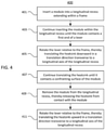
FIG. 4 is a flow chart in accordance with one aspect of the disclosure. - The technology relates generally to a cage configured to removably receive a module, such as a small form factor high power pluggable transceiver, and a method for removably inserting such a module into a cage. For example, and as illustrated in
FIGS. 1A through 2B , asystem 100 may include acage 110 and acircuit panel 120. Aframe 111 of thecage 110 may be fixedly mounted to amajor surface 121 of thecircuit panel 120 at aperipheral edge 122 thereof. Thecage 110 may be configured to removably receive amodule 102 therein. - The
module 102 may be a small form factor high power pluggable transceiver, which may be an optical module that has a high thermal load compared to conventional optical modules. The power consumption of such an optical module may require almost double the power consumption of a convention al optical module while maintaining the same exterior form factor. - The
frame 111 of thecage 110 may include a plurality ofpanels 112 joined to one another, the panels together extending around alongitudinal recess 113 configured to receive themodule 102 therein. Thelongitudinal recess 113 may define a longitudinal axis LA thereof that extends in opposite first and second longitudinal directions D1 and D2 between anopen end 114 and aclosed end 115 of the longitudinal recess, the open and closed ends being spaced apart from one another along the longitudinal axis. - A
first panel 116 of theframe 111 may have anaperture 117 defined therein in communication with thelongitudinal recess 113. As shown inFIGS. 1A through 2B , theaperture 117 may extend within a central portion of thefirst panel 116, but in other embodiments (not shown), the aperture may extend anywhere within the first panel. Theaperture 117 may occupy any amount of the area of thefirst panel 116, including for example, about 50% of the area of the first panel, between 40% and 60% of the area of the first panel, or between 25% and 75% of the area of the first panel, among others. - The
cage 110 may also include one ormore levers 130 each pivotally coupled to theframe 111. Thelevers 130 may each have afirst end 131 that extends into thelongitudinal recess 113 and asecond end 132 that is located opposite from the first end. As shown inFIGS. 1B and2B , there are two levers 130 (which may be afirst lever 130a and asecond lever 130b), but in other embodiments (not shown), there may be any number of levers pivotally coupled to theframe 111, such as one, three, four, five, six, or eight. The first end of eachlever 130 may extend into thelongitudinal recess 113 through asecond panel 118 of thepanels 112. Thesecond panel 118 may form theclosed end 115 of the longitudinal recess. - The
frame 111 may include afulcrum 133 fixedly mounted to one or more of thepanels 112. As shown inFIGS. 1A through 2B , thefulcrum 133 may be fixedly mounted to thefirst panel 116, but in other embodiments (not shown), the fulcrum may be fixedly mounted to anywhere within the first panel, anywhere within any of theother panels 112, or anywhere along thecircuit panel 120. Thelever 130 may be pivotably coupled to thefulcrum 113 at acentral portion 133 of the lever located between the first and second ends 131, 132. - The
cage 110 may also include one ormore heatsinks 140 each pivotably coupled to thesecond end 132 of one or more of thelevers 130 opposite thefirst end 131 thereof. As shown inFIGS. 1B and2B , asingle heatsink 140 is pivotably coupled to thesecond end 132 of twolevers 130, the levers being coupled to the heatsink on oppositelateral sides levers 130 may be coupled to theheatsink 140 at other locations, such as atop surface 142 of the heatsink. - The
heatsink 140 may be movable in a translation direction D3 transverse to the longitudinal axis LA, the heatsink being translatable between a first position P1 and a second position P2 as a result of the lever or levers 130 rotating relative to theframe 111. As shown in the figures, the first position P1 is outside of thelongitudinal recess 113, and the second position P2 is inside theaperture 117 and partially inside the longitudinal recess. - In other examples (not shown), the first position P1 may be inside the
aperture 117 and partially inside thelongitudinal recess 113, and the second position P2 may be partially or fully inside the longitudinal recess. The invention contemplates any locations of the first position P1 and the second position P2, so long as the second position extends further into thelongitudinal recess 113 than the first position, such that when themodule 102 is engaged within the longitudinal recess, the second position disposes abottom surface 143 of theheatsink 140 in complete or substantially complete surface contact with a top surface 104 (or confronting surface) of the module, and the first position disposes the bottom surface of the heatsink spaced apart from the top surface of the module. The surface contact between thebottom surface 143 of theheatsink 140 and thetop surface 104 of the module may occupy any amount of the area of the top surface of the module, including for example, about 50% of the area of the top surface of the module, between 40% and 60% of the area of the top surface of the module, or between 25% and 75% of the area of the top surface of the module, among others. - As shown in the figures, the translation D3 is perpendicular to the longitudinal axis LA, but that need always be the case. In other examples (not shown), the translation direction D3 may be transverse to the longitudinal axis LA, and may be for example, between 80 and 100 degrees relative to the longitudinal axis, between 75 and 115 degrees relative to the longitudinal axis, or between 60 and 120 degrees relative to the longitudinal axis, among others.
- The
cage 110 may also include anenergy storage element 150 coupled to thelever 130 and biasing theheatsink 140 towards the first position PI, such that the energy storage element is configured to translate the heatsink from the second position P2 to the first position when themodule 102 is removed from theframe 111. In one example, theenergy storage element 150 may be a coil spring that pivotally couples thelever 130 to thefulcrum 133, by having a first end that is fixedly attached to the lever and a second opposite end that is fixedly attached to the fulcrum. In other examples (not shown), other energy storage elements may be used in place of or in addition to the coil spring, such as a living hinge, an elastic polymer, or the like. - The one or
more levers 130 may each be configured to rotate about thefulcrum 133 as a result of contact between aninsertion end 106 of themodule 102 and thefirst end 131 of each of the levers that extends into thelongitudinal recess 113. As themodule 102 is inserted into theopen end 114 of thelongitudinal recess 113 and approaches theclosed end 115, theinsertion end 106 of the module moves increasingly closer to thefirst end 131 of thelevers 130. - This movement of the
insertion end 106 of themodule 102 can be seen by comparingFIG. 1A , in which the module is disposed outside of thelongitudinal recess 113, withFIG. 1B , in which the insertion end of the module contacts thefirst end 131 of thelevers 130. The rotating of thelevers 130 relative to theframe 111 begins when theinsertion end 106 of the module contacts thefirst end 131 of the levers. This contact between theinsertion end 106 of themodule 102 and thefirst end 131 of thelevers 130, in a situation in which the levers may not be visible to a user located outside of thelongitudinal recess 113, may be referred to as a "blind mate" or a "blind mating" between the module and the levers that actuates the movement of theheatsink 140 to place the heatsink in complete or substantially complete surface contact with the module. -
FIGS. 3A and 3B show asystem 100a that is a variation of thesystem 100 ofFIGS. 1A through 2B . All elements of thesystem 100a are the same as thesystem 100 except for those that are described below. All elements of thesystem 100 that are described above may be incorporated into thesystem 100a in the same way that they are described above. - The
system 100a includes acage 110a having alatch 135 that is either affixed to or pivotably coupled to thefirst end 131 of thelevers 130. Thelatch 135 may be configured to be removably coupled to themodule 102. Thelatch 135 may be coupled to thefirst end 131 of each thelevers 130, such that the latch is configured to translate theheatsink 140 from the second position P2 towards the first position P1 when themodule 102 is removed from theframe 111. Thelatch 135 may be configured to translate within thelongitudinal recess 113 along the longitudinal axis LA in the first and second directions D1, D2. - The
latch 135 may have two ormore protrusions 136 that may removably grip themodule 102 when theinsertion end 106 of the module is engaged into the latch. Theprotrusions 136 may be separated by a first width W1 that is less than a second width W2 of theinsertion end 106 of themodule 102, such that the insertion end of the module is press fit between the protrusions upon insertion into thelatch 135. - When a user desires to withdraw the
module 102 from thelongitudinal recess 113, the user may apply a first smaller pulling force in the second direction D2 that initially lifts theheatsink 140 out of engagement with thetop surface 104 of the module and moves the heatsink towards the first position P1. Then, the user may apply a second larger pulling force in the second direction D2 that is sufficient to overcome the press fit force between theprotrusions 136 and theinsertion end 106 of themodule 102, thereby releasing the module from thelatch 135. - Referring to
FIG. 4 , in addition to the operations described above and illustrated in the figures, various operations will now be described. The following operations do not have to be performed in the precise order described below. Rather, various steps can be handled in a different order or simultaneously, and steps may also be added or omitted.FIG. 4 illustrates aflow chart 400 showing an example insertion operation of themodule 102 into thecage block 401, themodule 102 may be inserted into thelongitudinal recess 113 of thecage - As shown in
block 403, themodule 102 may be inserted into thelongitudinal recess 113 within theframe 111 until theinsertion end 106 of the module contacts thefirst end 131 of thelevers 130, or alternatively with thecage 110a, until the insertion end of the module becomes engaged into thelatch 135. Next inblock 405, the contact between themodule 102 and the one ormore levers 130 causes the levers to simultaneously rotate relative to theframe 111, which thereby translates theheatsink 140 from the first position P1 downward in the translation direction D3 transverse to the longitudinal axis LA of thelongitudinal recess 113. - In
block 407, the one ormore levers 130 continue to rotate relative to theframe 111 and continue translating theheatsink 140 to the second position inside theaperture 117 and partially inside thelongitudinal recess 117, until thebottom surface 143 of the heatsink contacts the top surface 104 (or confronting surface) of themodule 102 with a complete or substantially complete surface contact. Next inblock 409, when it is desired to remove the module from thelongitudinal recess 113, a user or a robotic arm may apply a pulling force in the second direction D2 that lifts theheatsink 140 out of engagement with thetop surface 104 of themodule 102 and moves the heatsink back towards the first position P1. - In
block 411, when using thecage 110, theheatsink 140 is translated out of engagement with themodule 102 by release of energy stored in theenergy storage element 150 as theinsertion end 106 of the module releases its pressing force onto thefirst end 131 of thelevers 130. Alternatively, when using thecage 110a, theheatsink 140 is translated out of engagement with themodule 102 by thelatch 135 pulling thefirst end 131 of thelevers 130 generally in the second direction D2, and the module is withdrawn from the latch once the pulling force overcomes the press fit force between theprotrusions 136 and theinsertion end 106 of the module, thereby releasing the module from the latch. - Unless otherwise stated, the foregoing alternative examples are not mutually exclusive, but may be implemented in various combinations to achieve unique advantages. As these and other variations and combinations of the features discussed above can be utilized without departing from the subject matter defined by the claims, the foregoing description of the embodiments should be taken by way of illustration rather than by way of limitation of the subject matter defined by the claims. In addition, the provision of the examples described herein, as well as clauses phrased as "such as," "including" and the like, should not be interpreted as limiting the subject matter of the claims to the specific examples; rather, the examples are intended to illustrate only one of many possible embodiments. Further, the same reference numbers in different drawings can identify the same or similar elements.
Claims (15)
- A cage configured to removably receive a module, the cage comprising:a frame comprising a plurality of panels joined to one another, the panels together extending around a longitudinal recess configured to receive the module therein, the longitudinal recess defining a longitudinal axis thereof; a first one of the panels having an aperture defined therein in communication with the longitudinal recess;a lever pivotably coupled to the frame, a first end of the lever extending into the longitudinal recess;a heatsink pivotably coupled to a second end of the lever opposite the first end, the heatsink being movable in a translation direction transverse to the longitudinal axis, the heatsink being translatable between first and second positions as a result of the lever rotating relative to the frame, the first position being outside of the longitudinal recess, the second position being inside the aperture and partially inside the longitudinal recess.
- The cage of claim 1, wherein the lever is configured to rotate as a result of contact between an insertion end of the module and the first end of the lever, and/or
wherein the lever is a first lever, the cage further comprising a second lever pivotably coupled to the frame, a first end of the second lever extending into the longitudinal recess, a second end of the second lever being pivotably coupled to the heatsink, the heatsink being translatable between the first and second positions as a result of both the first and second levers simultaneously rotating relative to the frame. - The cage of claim 1 or 2, wherein the frame includes a fulcrum fixedly mounted to one or more of the panels, the lever being pivotably coupled to the fulcrum at a central portion of the lever located between the first and second ends, and/or
wherein the longitudinal recess has an open end and a closed end spaced apart from one another along the longitudinal axis, and the first end of the lever extends through a second one of the panels that forms the closed end of the longitudinal recess. - The cage of any one of claims 1 to 3, wherein the translation direction is perpendicular to the longitudinal axis.
- The cage of any one of claims 1 to 4, further comprising an energy storage element coupled to the lever and biasing the heatsink towards the first position, such that the energy storage element is configured to translate the heatsink from the second position to the first position when the module is removed from the frame.
- The cage of any one of claims 1 to 5, further comprising a latch configured to be removably coupled to the module, the latch being coupled to the first end of the lever, such that the latch is configured to translate the heatsink from the second position towards the first position when the module is removed from the frame.
- The cage of any one of claims 1 to 6, wherein the module is a small form factor high power pluggable transceiver.
- A system comprising a circuit panel and the cage of any one of claims 1 to 7, wherein the frame is fixedly mounted to a major surface of the circuit panel at a peripheral edge thereof.
- A method for removably inserting a module into a cage, the method comprising:inserting the module along a longitudinal axis into a longitudinal recess extending within a frame until the module contacts a first end of a lever that extends into the longitudinal recess, the lever being pivotably coupled to the frame, the frame comprising a plurality of panels joined to one another and together extending around the longitudinal recess, a first one of the panels having an aperture defined therein in communication with the longitudinal recess;rotating the lever relative to the frame; andtranslating a heatsink in a translation direction transverse to the longitudinal axis from a first position outside of the longitudinal recess to a second position inside the aperture and partially inside the longitudinal recess, the heatsink being pivotably coupled to a second end of the lever opposite the first end, the heatsink translating between the first and second positions as a result of the lever rotating relative to the frame.
- The method of claim 9, wherein the lever is rotated as a result of contact between an insertion end of the module and the first end of the lever, and the rotating of the lever relative to the frame begins when the insertion end of the module contacts the first end of the lever, and/or
wherein the lever is a first lever, the cage further comprising a second lever pivotably coupled to the frame, a first end of the second lever extending into the longitudinal recess, a second end of the second lever being pivotably coupled to the heatsink, the heatsink translating between the first and second positions as a result of both the first and second levers simultaneously rotating relative to the frame. - The method of claim 9 or 10, wherein the frame includes a fulcrum fixedly mounted to one or more of the panels, the lever being pivotably coupled to the fulcrum at a central portion of the lever located between the first and second ends, and/or
wherein the longitudinal recess has an open end and a closed end spaced apart from one another along the longitudinal axis, and the first end of the lever extends through a second one of the panels that forms the closed end of the longitudinal recess. - The method of any one of claims 9 to 11, wherein the translation direction is perpendicular to the longitudinal axis.
- The method of any one of claims 9 to 12, further comprising removing the module from the longitudinal recess and translating the heatsink from the second position to the first position as a result of the lever rotating relative to the frame, the translation of the heatsink from the second position to the first position being accomplished by release of energy stored in an energy storage component coupled to the lever and biasing the heatsink towards the first position.
- The method of any one of claims 9 to 13, further comprising removing the module from the longitudinal recess and translating the heatsink from the second position to the first position as a result of the lever rotating relative to the frame, the translation of the heatsink from the second position to the first position being accomplished by a latch removably coupled to the first end of the lever, so that the latch is configured to move the heatsink from the second position towards the first position when the module is removed from the frame.
- The method of any one of claims 9 to 14, wherein the module is a small form factor high power pluggable transceiver, and/or
wherein the frame is fixedly mounted to a major surface of a circuit panel at a peripheral edge thereof.
Applications Claiming Priority (1)
| Application Number | Priority Date | Filing Date | Title |
|---|---|---|---|
| US16/993,976 US11462852B2 (en) | 2020-08-14 | 2020-08-14 | Blind mate thermal cooling solution for small form factor pluggable transceiver |
Publications (2)
| Publication Number | Publication Date |
|---|---|
| EP3955039A1 true EP3955039A1 (en) | 2022-02-16 |
| EP3955039B1 EP3955039B1 (en) | 2025-09-10 |
Family
ID=75870364
Family Applications (1)
| Application Number | Title | Priority Date | Filing Date |
|---|---|---|---|
| EP21172212.9A Active EP3955039B1 (en) | 2020-08-14 | 2021-05-05 | Blind mate thermal cooling solution for small form factor pluggable transceiver |
Country Status (2)
| Country | Link |
|---|---|
| US (1) | US11462852B2 (en) |
| EP (1) | EP3955039B1 (en) |
Cited By (2)
| Publication number | Priority date | Publication date | Assignee | Title |
|---|---|---|---|---|
| CN114759391A (en) * | 2022-05-09 | 2022-07-15 | 苏州意华通讯接插件有限公司 | Heat radiation assembly and electric connector thereof |
| EP4390487A1 (en) * | 2022-12-20 | 2024-06-26 | Juniper Networks, Inc. | Actuating heatsink for pluggable modules |
Families Citing this family (11)
| Publication number | Priority date | Publication date | Assignee | Title |
|---|---|---|---|---|
| WO2021249640A1 (en) * | 2020-06-10 | 2021-12-16 | Telefonaktiebolaget Lm Ericsson (Publ) | A connector system |
| CN115119464B (en) * | 2021-03-22 | 2025-07-15 | 华为技术有限公司 | Heat dissipation device and communication equipment |
| US11765848B2 (en) * | 2021-07-29 | 2023-09-19 | Hewlett Packard Enterprise Development Lp | Host electronic device having a movable cooling component for removable electronic device |
| EP4135493B1 (en) * | 2021-08-12 | 2026-04-08 | Nokia Solutions and Networks Oy | Apparatus comprising a heat sink for a pluggable module |
| US11700712B2 (en) * | 2021-08-31 | 2023-07-11 | Hewlett Packard Enterprise Development Lp | Floating heat sink for use with a thermal interface material |
| US11706900B1 (en) * | 2022-01-14 | 2023-07-18 | Dell Products L.P. | Passive and active environmental management of an information handling system |
| CN119095696A (en) * | 2022-02-09 | 2024-12-06 | 豪倍公司 | Variable sleeve with offset ramp assembly |
| US11789220B1 (en) * | 2022-03-28 | 2023-10-17 | Amazon Technologies, Inc. | Liftable heat sink design with thermal interface material for pluggable optical modules |
| US12439564B2 (en) * | 2023-07-31 | 2025-10-07 | Hewlett Packard Enterprise Development Lp | Lever actuated cold plate |
| US20250258349A1 (en) * | 2024-02-08 | 2025-08-14 | Ciena Corporation | Apparatus and method for managing temperature of a high-power pluggable optical module |
| US20250280515A1 (en) * | 2024-02-29 | 2025-09-04 | Hewlett Packard Enterprise Development Lp | Cooling interface for a pluggable module |
Citations (3)
| Publication number | Priority date | Publication date | Assignee | Title |
|---|---|---|---|---|
| US20170269314A1 (en) * | 2016-03-17 | 2017-09-21 | Ciena Corporation | Optical module heatsink lifter and method |
| US10539753B1 (en) * | 2018-10-31 | 2020-01-21 | Hewlett Packard Enterprise Development Lp | Liquid-cooled assembly |
| US20200260615A1 (en) * | 2018-10-31 | 2020-08-13 | Hewlett Packard Enterprise Development Lp | Rotatable cold plate assembly for cooling pluggable modules |
Family Cites Families (24)
| Publication number | Priority date | Publication date | Assignee | Title |
|---|---|---|---|---|
| US5598320A (en) | 1995-03-06 | 1997-01-28 | Ast Research, Inc. | Rotable and slideble heat pipe apparatus for reducing heat build up in electronic devices |
| JP2885736B2 (en) | 1996-11-22 | 1999-04-26 | 宮城日本電気株式会社 | Electronic device cooling structure |
| JP3302350B2 (en) | 2000-06-29 | 2002-07-15 | 株式会社東芝 | Electronics |
| JP2003059602A (en) * | 2001-08-08 | 2003-02-28 | Yamaichi Electronics Co Ltd | Socket for semiconductor device |
| JP4251452B2 (en) | 2002-03-06 | 2009-04-08 | タイコ・エレクトロニクス・コーポレイション | Ejector mechanism of transceiver module assembly |
| US7371965B2 (en) | 2002-05-09 | 2008-05-13 | Finisar Corporation | Modular cage with heat sink for use with pluggable module |
| GB2401250B (en) * | 2003-04-29 | 2006-05-17 | Agilent Technologies Inc | Heat sink |
| US7048452B2 (en) | 2003-11-10 | 2006-05-23 | Jds Uniphase Corporation | Transceiver guide rail with heat sink guide |
| US6980437B2 (en) | 2004-03-03 | 2005-12-27 | Tyco Electronics Corporation | Pluggable electronic receptacle with heat sink assembly |
| TWI242940B (en) | 2004-08-06 | 2005-11-01 | Ind Tech Res Inst | Exerted bolting mechanism of plug-and-play optical module |
| US7355857B2 (en) | 2006-02-07 | 2008-04-08 | Methode Electronics, Inc. | Heat sink gasket |
| US7529094B2 (en) * | 2006-04-28 | 2009-05-05 | Tyco Electronics Corporation | Integrated heat sink and light pipe mounting assembly |
| US7539018B2 (en) * | 2007-10-31 | 2009-05-26 | Tyco Electronics Corporation | Heat sink retaining clip for an electrical connector assembly |
| JP4998249B2 (en) | 2007-12-21 | 2012-08-15 | 住友電気工業株式会社 | Optical transceiver heat dissipation device |
| JP4915342B2 (en) * | 2007-12-21 | 2012-04-11 | 住友電気工業株式会社 | Optical transceiver heat dissipation device |
| US7733652B2 (en) | 2008-09-17 | 2010-06-08 | Tyco Electronics Corporation | Heat sink assembly for a pluggable module |
| US8035973B2 (en) | 2009-08-31 | 2011-10-11 | Avago Technologies Fiber Ip (Singapore) Pte. Ltd. | Cage having a heat sink device secured thereto in a floating arrangement that ensures that continuous contact is maintained between the heat sink device and a parallel optical communications device secured to the cage |
| WO2011120188A1 (en) | 2010-03-29 | 2011-10-06 | Telefonaktiebolaget L M Ericsson (Publ) | Cooling device for pluggable module, assembly of the cooling device and the pluggable module |
| US8345445B2 (en) | 2010-11-23 | 2013-01-01 | Tyco Electronics Corporation | Heat sink assembly for a pluggable module |
| US8485739B2 (en) | 2011-03-30 | 2013-07-16 | Avago Technologies General Ip (Singapore) Pte. Ltd. | Optical transceiver module having a deformable heat sink structure |
| JP5673349B2 (en) * | 2011-05-25 | 2015-02-18 | 富士通株式会社 | Pluggable module |
| US8670236B2 (en) | 2011-08-03 | 2014-03-11 | Tyco Electronics Corporation | Cage assembly for receiving a pluggable module |
| JP2019015795A (en) * | 2017-07-04 | 2019-01-31 | 住友電工デバイス・イノベーション株式会社 | Optical transceiver |
| US10567084B2 (en) | 2017-12-18 | 2020-02-18 | Honeywell International Inc. | Thermal interface structure for optical transceiver modules |
-
2020
- 2020-08-14 US US16/993,976 patent/US11462852B2/en active Active
-
2021
- 2021-05-05 EP EP21172212.9A patent/EP3955039B1/en active Active
Patent Citations (3)
| Publication number | Priority date | Publication date | Assignee | Title |
|---|---|---|---|---|
| US20170269314A1 (en) * | 2016-03-17 | 2017-09-21 | Ciena Corporation | Optical module heatsink lifter and method |
| US10539753B1 (en) * | 2018-10-31 | 2020-01-21 | Hewlett Packard Enterprise Development Lp | Liquid-cooled assembly |
| US20200260615A1 (en) * | 2018-10-31 | 2020-08-13 | Hewlett Packard Enterprise Development Lp | Rotatable cold plate assembly for cooling pluggable modules |
Cited By (4)
| Publication number | Priority date | Publication date | Assignee | Title |
|---|---|---|---|---|
| CN114759391A (en) * | 2022-05-09 | 2022-07-15 | 苏州意华通讯接插件有限公司 | Heat radiation assembly and electric connector thereof |
| CN114759391B (en) * | 2022-05-09 | 2023-12-08 | 苏州意华通讯接插件有限公司 | Radiating assembly and electric connector thereof |
| EP4390487A1 (en) * | 2022-12-20 | 2024-06-26 | Juniper Networks, Inc. | Actuating heatsink for pluggable modules |
| US12324129B2 (en) | 2022-12-20 | 2025-06-03 | Juniper Networks, Inc. | Actuating heatsink for pluggable modules |
Also Published As
| Publication number | Publication date |
|---|---|
| US20220052474A1 (en) | 2022-02-17 |
| EP3955039B1 (en) | 2025-09-10 |
| US11462852B2 (en) | 2022-10-04 |
Similar Documents
| Publication | Publication Date | Title |
|---|---|---|
| EP3955039B1 (en) | Blind mate thermal cooling solution for small form factor pluggable transceiver | |
| US6652301B2 (en) | Ejector mechanism for card connector | |
| US7581959B2 (en) | Printed circuit board engagement systems and methods | |
| US7733652B2 (en) | Heat sink assembly for a pluggable module | |
| EP1113529B1 (en) | Connector for module | |
| US5930426A (en) | Optical fiber connector | |
| US6118659A (en) | Heat sink clamping spring additionally holding a ZIF socket locked | |
| JP4651592B2 (en) | PIU insertion / extraction mechanism for electronic devices | |
| EP0450211B1 (en) | Contact shutter device in ic socket | |
| US7040911B1 (en) | Transceiver module with cam-based delatching actuator | |
| EP0678824A1 (en) | Universal ejector mechanism for an IC card connector apparatus | |
| WO2021134657A1 (en) | Optical module unlocking device, optical module, and optical communication device | |
| US20210242628A1 (en) | Electronic device with capability of lever ejection and lever mechanism thereof | |
| JP3556090B2 (en) | Connector device for IC card | |
| WO2024234744A1 (en) | Heat dissipation apparatus | |
| JP5136651B2 (en) | Connector removal tool and connector removal method using the same | |
| US5037321A (en) | Connector for electric part | |
| US20080080156A1 (en) | Multi-point latch mechanism with a single control | |
| US20090016011A1 (en) | Module and a method of positioning a module | |
| US7059887B1 (en) | Optoelectric module with pop-out tab based latching/delatching mechanism | |
| DE102021126994A1 (en) | HOST ELECTRONIC DEVICE HAVING A MOVABLE COOLING COMPONENT FOR A REMOVABLE ELECTRONIC DEVICE | |
| JP3483451B2 (en) | Connector device for IC card | |
| US20090091224A1 (en) | Slide module structure for a drawer | |
| TW202535133A (en) | Tray with moveable connector for chassis side plane engagement | |
| JP3483449B2 (en) | Connector device for IC card |
Legal Events
| Date | Code | Title | Description |
|---|---|---|---|
| PUAI | Public reference made under article 153(3) epc to a published international application that has entered the european phase |
Free format text: ORIGINAL CODE: 0009012 |
|
| STAA | Information on the status of an ep patent application or granted ep patent |
Free format text: STATUS: THE APPLICATION HAS BEEN PUBLISHED |
|
| AK | Designated contracting states |
Kind code of ref document: A1 Designated state(s): AL AT BE BG CH CY CZ DE DK EE ES FI FR GB GR HR HU IE IS IT LI LT LU LV MC MK MT NL NO PL PT RO RS SE SI SK SM TR |
|
| STAA | Information on the status of an ep patent application or granted ep patent |
Free format text: STATUS: REQUEST FOR EXAMINATION WAS MADE |
|
| 17P | Request for examination filed |
Effective date: 20220808 |
|
| RBV | Designated contracting states (corrected) |
Designated state(s): AL AT BE BG CH CY CZ DE DK EE ES FI FR GB GR HR HU IE IS IT LI LT LU LV MC MK MT NL NO PL PT RO RS SE SI SK SM TR |
|
| STAA | Information on the status of an ep patent application or granted ep patent |
Free format text: STATUS: EXAMINATION IS IN PROGRESS |
|
| 17Q | First examination report despatched |
Effective date: 20230602 |
|
| GRAP | Despatch of communication of intention to grant a patent |
Free format text: ORIGINAL CODE: EPIDOSNIGR1 |
|
| STAA | Information on the status of an ep patent application or granted ep patent |
Free format text: STATUS: GRANT OF PATENT IS INTENDED |
|
| INTG | Intention to grant announced |
Effective date: 20250402 |
|
| GRAS | Grant fee paid |
Free format text: ORIGINAL CODE: EPIDOSNIGR3 |
|
| GRAA | (expected) grant |
Free format text: ORIGINAL CODE: 0009210 |
|
| STAA | Information on the status of an ep patent application or granted ep patent |
Free format text: STATUS: THE PATENT HAS BEEN GRANTED |
|
| AK | Designated contracting states |
Kind code of ref document: B1 Designated state(s): AL AT BE BG CH CY CZ DE DK EE ES FI FR GB GR HR HU IE IS IT LI LT LU LV MC MK MT NL NO PL PT RO RS SE SI SK SM TR |
|
| P01 | Opt-out of the competence of the unified patent court (upc) registered |
Free format text: CASE NUMBER: UPC_APP_2161_3955039/2025 Effective date: 20250801 |
|
| REG | Reference to a national code |
Ref country code: GB Ref legal event code: FG4D |
|
| REG | Reference to a national code |
Ref country code: CH Ref legal event code: EP |
|
| REG | Reference to a national code |
Ref country code: DE Ref legal event code: R096 Ref document number: 602021038152 Country of ref document: DE |
|
| REG | Reference to a national code |
Ref country code: IE Ref legal event code: FG4D |
|
| REG | Reference to a national code |
Ref country code: NL Ref legal event code: FP |
|
| PG25 | Lapsed in a contracting state [announced via postgrant information from national office to epo] |
Ref country code: NO Free format text: LAPSE BECAUSE OF FAILURE TO SUBMIT A TRANSLATION OF THE DESCRIPTION OR TO PAY THE FEE WITHIN THE PRESCRIBED TIME-LIMIT Effective date: 20251210 |
|
| REG | Reference to a national code |
Ref country code: LT Ref legal event code: MG9D |
|
| PG25 | Lapsed in a contracting state [announced via postgrant information from national office to epo] |
Ref country code: FI Free format text: LAPSE BECAUSE OF FAILURE TO SUBMIT A TRANSLATION OF THE DESCRIPTION OR TO PAY THE FEE WITHIN THE PRESCRIBED TIME-LIMIT Effective date: 20250910 |
|
| PG25 | Lapsed in a contracting state [announced via postgrant information from national office to epo] |
Ref country code: HR Free format text: LAPSE BECAUSE OF FAILURE TO SUBMIT A TRANSLATION OF THE DESCRIPTION OR TO PAY THE FEE WITHIN THE PRESCRIBED TIME-LIMIT Effective date: 20250910 |
|
| PG25 | Lapsed in a contracting state [announced via postgrant information from national office to epo] |
Ref country code: GR Free format text: LAPSE BECAUSE OF FAILURE TO SUBMIT A TRANSLATION OF THE DESCRIPTION OR TO PAY THE FEE WITHIN THE PRESCRIBED TIME-LIMIT Effective date: 20251211 |
|
| PG25 | Lapsed in a contracting state [announced via postgrant information from national office to epo] |
Ref country code: SE Free format text: LAPSE BECAUSE OF FAILURE TO SUBMIT A TRANSLATION OF THE DESCRIPTION OR TO PAY THE FEE WITHIN THE PRESCRIBED TIME-LIMIT Effective date: 20250910 |
|
| PG25 | Lapsed in a contracting state [announced via postgrant information from national office to epo] |
Ref country code: LV Free format text: LAPSE BECAUSE OF FAILURE TO SUBMIT A TRANSLATION OF THE DESCRIPTION OR TO PAY THE FEE WITHIN THE PRESCRIBED TIME-LIMIT Effective date: 20250910 |
|
| PG25 | Lapsed in a contracting state [announced via postgrant information from national office to epo] |
Ref country code: PL Free format text: LAPSE BECAUSE OF FAILURE TO SUBMIT A TRANSLATION OF THE DESCRIPTION OR TO PAY THE FEE WITHIN THE PRESCRIBED TIME-LIMIT Effective date: 20250910 Ref country code: BG Free format text: LAPSE BECAUSE OF FAILURE TO SUBMIT A TRANSLATION OF THE DESCRIPTION OR TO PAY THE FEE WITHIN THE PRESCRIBED TIME-LIMIT Effective date: 20250910 |
|
| PG25 | Lapsed in a contracting state [announced via postgrant information from national office to epo] |
Ref country code: RS Free format text: LAPSE BECAUSE OF FAILURE TO SUBMIT A TRANSLATION OF THE DESCRIPTION OR TO PAY THE FEE WITHIN THE PRESCRIBED TIME-LIMIT Effective date: 20251210 |
|
| PG25 | Lapsed in a contracting state [announced via postgrant information from national office to epo] |
Ref country code: ES Free format text: LAPSE BECAUSE OF FAILURE TO SUBMIT A TRANSLATION OF THE DESCRIPTION OR TO PAY THE FEE WITHIN THE PRESCRIBED TIME-LIMIT Effective date: 20250910 |
|
| REG | Reference to a national code |
Ref country code: AT Ref legal event code: MK05 Ref document number: 1836466 Country of ref document: AT Kind code of ref document: T Effective date: 20250910 |
|
| PG25 | Lapsed in a contracting state [announced via postgrant information from national office to epo] |
Ref country code: SM Free format text: LAPSE BECAUSE OF FAILURE TO SUBMIT A TRANSLATION OF THE DESCRIPTION OR TO PAY THE FEE WITHIN THE PRESCRIBED TIME-LIMIT Effective date: 20250910 |
|
| PG25 | Lapsed in a contracting state [announced via postgrant information from national office to epo] |
Ref country code: AT Free format text: LAPSE BECAUSE OF FAILURE TO SUBMIT A TRANSLATION OF THE DESCRIPTION OR TO PAY THE FEE WITHIN THE PRESCRIBED TIME-LIMIT Effective date: 20250910 |
|
| PG25 | Lapsed in a contracting state [announced via postgrant information from national office to epo] |
Ref country code: IT Free format text: LAPSE BECAUSE OF FAILURE TO SUBMIT A TRANSLATION OF THE DESCRIPTION OR TO PAY THE FEE WITHIN THE PRESCRIBED TIME-LIMIT Effective date: 20250910 |
|
| PG25 | Lapsed in a contracting state [announced via postgrant information from national office to epo] |
Ref country code: IS Free format text: LAPSE BECAUSE OF FAILURE TO SUBMIT A TRANSLATION OF THE DESCRIPTION OR TO PAY THE FEE WITHIN THE PRESCRIBED TIME-LIMIT Effective date: 20260110 |
|
| PG25 | Lapsed in a contracting state [announced via postgrant information from national office to epo] |
Ref country code: CZ Free format text: LAPSE BECAUSE OF FAILURE TO SUBMIT A TRANSLATION OF THE DESCRIPTION OR TO PAY THE FEE WITHIN THE PRESCRIBED TIME-LIMIT Effective date: 20250910 Ref country code: PT Free format text: LAPSE BECAUSE OF FAILURE TO SUBMIT A TRANSLATION OF THE DESCRIPTION OR TO PAY THE FEE WITHIN THE PRESCRIBED TIME-LIMIT Effective date: 20260112 |
|
| PG25 | Lapsed in a contracting state [announced via postgrant information from national office to epo] |
Ref country code: EE Free format text: LAPSE BECAUSE OF FAILURE TO SUBMIT A TRANSLATION OF THE DESCRIPTION OR TO PAY THE FEE WITHIN THE PRESCRIBED TIME-LIMIT Effective date: 20250910 Ref country code: SK Free format text: LAPSE BECAUSE OF FAILURE TO SUBMIT A TRANSLATION OF THE DESCRIPTION OR TO PAY THE FEE WITHIN THE PRESCRIBED TIME-LIMIT Effective date: 20250910 |