EP3954910A1 - Improved expansion anchor - Google Patents
Improved expansion anchor Download PDFInfo
- Publication number
- EP3954910A1 EP3954910A1 EP21173262.3A EP21173262A EP3954910A1 EP 3954910 A1 EP3954910 A1 EP 3954910A1 EP 21173262 A EP21173262 A EP 21173262A EP 3954910 A1 EP3954910 A1 EP 3954910A1
- Authority
- EP
- European Patent Office
- Prior art keywords
- expansion
- proximal
- segment
- distal
- expansion anchor
- Prior art date
- Legal status (The legal status is an assumption and is not a legal conclusion. Google has not performed a legal analysis and makes no representation as to the accuracy of the status listed.)
- Granted
Links
Images





Classifications
-
- F—MECHANICAL ENGINEERING; LIGHTING; HEATING; WEAPONS; BLASTING
- F16—ENGINEERING ELEMENTS AND UNITS; GENERAL MEASURES FOR PRODUCING AND MAINTAINING EFFECTIVE FUNCTIONING OF MACHINES OR INSTALLATIONS; THERMAL INSULATION IN GENERAL
- F16B—DEVICES FOR FASTENING OR SECURING CONSTRUCTIONAL ELEMENTS OR MACHINE PARTS TOGETHER, e.g. NAILS, BOLTS, CIRCLIPS, CLAMPS, CLIPS OR WEDGES; JOINTS OR JOINTING
- F16B13/00—Dowels or other devices fastened in walls or the like by inserting them in holes made therein for that purpose
- F16B13/04—Dowels or other devices fastened in walls or the like by inserting them in holes made therein for that purpose with parts gripping in the hole or behind the reverse side of the wall after inserting from the front
- F16B13/08—Dowels or other devices fastened in walls or the like by inserting them in holes made therein for that purpose with parts gripping in the hole or behind the reverse side of the wall after inserting from the front with separate or non-separate gripping parts moved into their final position in relation to the body of the device without further manual operation
- F16B13/0866—Dowels or other devices fastened in walls or the like by inserting them in holes made therein for that purpose with parts gripping in the hole or behind the reverse side of the wall after inserting from the front with separate or non-separate gripping parts moved into their final position in relation to the body of the device without further manual operation with prongs penetrating into the wall of the hole by a retractile movement of a threaded member
-
- F—MECHANICAL ENGINEERING; LIGHTING; HEATING; WEAPONS; BLASTING
- F16—ENGINEERING ELEMENTS AND UNITS; GENERAL MEASURES FOR PRODUCING AND MAINTAINING EFFECTIVE FUNCTIONING OF MACHINES OR INSTALLATIONS; THERMAL INSULATION IN GENERAL
- F16B—DEVICES FOR FASTENING OR SECURING CONSTRUCTIONAL ELEMENTS OR MACHINE PARTS TOGETHER, e.g. NAILS, BOLTS, CIRCLIPS, CLAMPS, CLIPS OR WEDGES; JOINTS OR JOINTING
- F16B13/00—Dowels or other devices fastened in walls or the like by inserting them in holes made therein for that purpose
- F16B13/04—Dowels or other devices fastened in walls or the like by inserting them in holes made therein for that purpose with parts gripping in the hole or behind the reverse side of the wall after inserting from the front
- F16B13/045—Dowels or other devices fastened in walls or the like by inserting them in holes made therein for that purpose with parts gripping in the hole or behind the reverse side of the wall after inserting from the front having axially compressing parts allowing the clamping of an object tightly to the wall
-
- F—MECHANICAL ENGINEERING; LIGHTING; HEATING; WEAPONS; BLASTING
- F16—ENGINEERING ELEMENTS AND UNITS; GENERAL MEASURES FOR PRODUCING AND MAINTAINING EFFECTIVE FUNCTIONING OF MACHINES OR INSTALLATIONS; THERMAL INSULATION IN GENERAL
- F16B—DEVICES FOR FASTENING OR SECURING CONSTRUCTIONAL ELEMENTS OR MACHINE PARTS TOGETHER, e.g. NAILS, BOLTS, CIRCLIPS, CLAMPS, CLIPS OR WEDGES; JOINTS OR JOINTING
- F16B13/00—Dowels or other devices fastened in walls or the like by inserting them in holes made therein for that purpose
- F16B13/04—Dowels or other devices fastened in walls or the like by inserting them in holes made therein for that purpose with parts gripping in the hole or behind the reverse side of the wall after inserting from the front
- F16B13/06—Dowels or other devices fastened in walls or the like by inserting them in holes made therein for that purpose with parts gripping in the hole or behind the reverse side of the wall after inserting from the front combined with expanding sleeve
- F16B13/061—Dowels or other devices fastened in walls or the like by inserting them in holes made therein for that purpose with parts gripping in the hole or behind the reverse side of the wall after inserting from the front combined with expanding sleeve of the buckling type
-
- F—MECHANICAL ENGINEERING; LIGHTING; HEATING; WEAPONS; BLASTING
- F16—ENGINEERING ELEMENTS AND UNITS; GENERAL MEASURES FOR PRODUCING AND MAINTAINING EFFECTIVE FUNCTIONING OF MACHINES OR INSTALLATIONS; THERMAL INSULATION IN GENERAL
- F16B—DEVICES FOR FASTENING OR SECURING CONSTRUCTIONAL ELEMENTS OR MACHINE PARTS TOGETHER, e.g. NAILS, BOLTS, CIRCLIPS, CLAMPS, CLIPS OR WEDGES; JOINTS OR JOINTING
- F16B13/00—Dowels or other devices fastened in walls or the like by inserting them in holes made therein for that purpose
- F16B13/04—Dowels or other devices fastened in walls or the like by inserting them in holes made therein for that purpose with parts gripping in the hole or behind the reverse side of the wall after inserting from the front
- F16B13/06—Dowels or other devices fastened in walls or the like by inserting them in holes made therein for that purpose with parts gripping in the hole or behind the reverse side of the wall after inserting from the front combined with expanding sleeve
- F16B13/063—Dowels or other devices fastened in walls or the like by inserting them in holes made therein for that purpose with parts gripping in the hole or behind the reverse side of the wall after inserting from the front combined with expanding sleeve by the use of an expander
-
- F—MECHANICAL ENGINEERING; LIGHTING; HEATING; WEAPONS; BLASTING
- F16—ENGINEERING ELEMENTS AND UNITS; GENERAL MEASURES FOR PRODUCING AND MAINTAINING EFFECTIVE FUNCTIONING OF MACHINES OR INSTALLATIONS; THERMAL INSULATION IN GENERAL
- F16B—DEVICES FOR FASTENING OR SECURING CONSTRUCTIONAL ELEMENTS OR MACHINE PARTS TOGETHER, e.g. NAILS, BOLTS, CIRCLIPS, CLAMPS, CLIPS OR WEDGES; JOINTS OR JOINTING
- F16B13/00—Dowels or other devices fastened in walls or the like by inserting them in holes made therein for that purpose
- F16B13/12—Separate metal or non-separate or non-metal dowel sleeves fastened by inserting the screw, nail or the like
Definitions
- the present invention relates to an expansion anchor, in particular, but not exclusively, to an expansion anchor suitable for use in the construction sector for anchoring, such as for a load to a wall and/or for a load to a top of a surface.
- a first type of expansion anchor consists of anchors made entirely of plastic, some of which are designed for anchoring to walls made of bricks with internal partitions defining internal cavities which are hollow or filled with low-density material, and/or walls made of a relatively friable or non-homogeneous materials, such as multi-layer walls, wall made of loose (i.e. not very compact) granular-concrete, and/or walls made of compact material and therefore having a high density, such as concrete walls or walls made of natural stone or solid bricks, or another high-density material.
- plastic expansion anchors are used in a wide range of applications, but their use is limited to the anchoring of loads having a relatively low weight. Plastic expansion anchors are unable to anchor loads having medium duty weight.
- the second type of anchor differs from the plastic expansion anchor essentially in that it includes a tubular body made of metal.
- the tubular body typically comprises a metal conduit with an anchoring tab.
- the anchor having the metal tubular body further comprises a conical body and a tightening screw.
- the conical body is attached at the end of the tightening screw.
- Wedges of the conical body are gradually urged or otherwise driven radially outwards between the anchoring tabs, moving them apart towards the inside wall of the hole in which the anchor is placed.
- the anchoring tabs are moved apart until they are positioned into abutment against the inside surface (i.e. hole) of the wall, securing the anchor into the hole in the wall using friction and using mechanical locking.
- Metal anchors of this type are able to anchor loads to a greater extent compared to the plastic anchors.
- an anchor that is unable to provide the required retention may loosen or detach from the desired surface during use.
- Another problem associated with existing anchors is the lack of confirmation to a user that the anchor is completely, correctly, and securely fitted. Without such confirmation or indication to the user, a user may continue to tighten the anchor, causing overtightening of the anchor and/or damage to the surface in which the anchor is set.
- another problem associated with expansion anchors is the generation of pressure points from the expanding legs of the anchor that directly engage with the anchor screw thread. If the legs of the anchor expand in an uncontrolled manner, the contact between the legs of the anchor and the screw thread of the anchor causes damage to the anchor. In some instances, the damage is detrimental to the functioning of the anchor.
- an expansion anchor that can alleviate or mitigate one or more of the aforementioned problems.
- the present invention provides at least an alternative to expansion anchors of the prior art.
- an expansion anchor comprising: a tubular sleeve having a longitudinal axis and comprising an expansion portion at a distal end and a body portion at a proximal end and expansion tabs attached to the body portion and extending towards the distal end; a tightening screw configured to move the expansion portion along the longitudinal axis inside the expansion tabs so as to expand the tabs radially outwardly relative to the longitudinal axis; at least one deformable leg extending between and attached to the body portion and to the expansion portion of the tubular sleeve, the deformable leg comprising at least two coupled segments, a distal segment, having a first attachment portion linking the distal segment to the expansion portion and a proximal segment, having a second attachment portion linking the proximal segment to the body portion, wherein the width of the proximal segment increases towards the proximal end of the tubular sleeve.
- the deformable leg is reinforced near the proximal end.
- This provides a wider surface area at the proximal end of the deformable leg, allowing an increased surface area to be in contact with the wall, which improves the mechanical performance of the expansion anchor and increases the load capacity of the expansion anchor.
- this allows the deformation of the deformable legs to be controlled, so as to prevent a pressure point onto the tightening screw to be generated.
- the first and second attachment portions may be circumferentially offset from each other about the longitudinal axis, so as to deform the deformable leg torsionally and radially outwardly relative to the longitudinal axis when moving the expansion portion from the distal end towards the proximal end.
- This is particularly beneficial because the proximal segment and the distal segment of the leg both engage with the surface to be engaged, in order to increase the surface area of engagement between the anchor and the surface.
- deformable leg(s) expand radially outwardly and torsionally to engage with the surface in which the anchor is set.
- the proximal segment and the distal segment of the leg both engage with the surface to increase the surface area of engagement between the anchor and the surface. This improves mechanical stability of the anchor in the wall, which increases the load capacity of the expansion anchor.
- the width of the proximal segment may increase uniformly towards the proximal end.
- the width of the distal segment may increase towards the distal end of the tubular sleeve.
- the width of the distal segment may increase uniformly towards the distal end.
- the expansion tabs may have a first rigidity
- the deformable legs may have a second rigidity greater than the first rigidity.
- the at least one deformable leg may comprise a first line of weakening between the distal segment and the proximal segment, having a width less than the distal and proximal segments. This provides a predetermined point of deformable at which the distal and proximal segments move relative to one another.
- said first line of weakening may have a width less than said distal and proximal segments.
- said at least one deformable leg may comprise an outwardly facing second line of weakening provided between said first attachment portion and said distal segment.
- said second line of weakening may be positioned proximal to said expansion portion.
- said first attachment portion may further comprise a recess, arranged so as to continue from said second line of weakening and separating a portion of said distal segment from said expansion portion, and a ramped surface, configured to guidingly move said portion of said distal segment away from said longitudinal axis, during use.
- said expansion anchor may comprise at least two deformable legs arranged adjacent to one another, each one adapted to stoppingly engage at a predetermined deformation, so as to prevent additional torsional and radial deformation, during use.
- said at least two deformable legs may be circumferentially equidistantly spaced about said longitudinal axis.
- said expansion anchor may further comprise a sleeve member coaxially arranged between said body portion and said tightening screw.
- a distal end of said sleeve member may be adapted to operably engage with said expansion portion, so as to prevent contact between said tightening screw and said expansion portion moving from said distal end to said proximal end.
- said sleeve member may be provided at said proximal end of said tubular sleeve.
- the described example embodiment relates to an expansion anchor and particularly to an expansion anchor for use in the construction sector.
- the invention is not necessarily restricted expansion anchors for use in the construction sector altogether but may also be used to secure a plurality of components together.
- the terms 'connected', 'attached', 'coupled', 'mounted' are intended to include direct connections between two members without any other members interposed therebetween, as well as, indirect connections between members in which one or more other members are interposed therebetween.
- the terminology includes the words specifically mentioned above, derivatives thereof, and words of similar import.
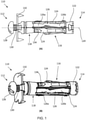
- Figure 1 (A) and Figure 1 (B) show an anchoring member, namely a medium duty expansion anchor 110 that is suitable for insertion in an anchoring hole of a support or a wall.
- the meaning of light duty, medium duty and high duty are all common terms in the art and would be understood within the common general knowledge of the person skilled in the art.
- the expansion anchor 10 has a proximal end 112 and a distal end 114 and is structured such that it may be anchored or otherwise secured to a support or wall. It is preferable, though not essential, that the anchor 110 comprises a metal structure. It shall be understood that the anchor 110 may be secured to any wall structure.
- the wall may be a solid structure or a non-solid structure.
- the wall may be made from bricks, or the wall may be hollow, having defining spaces and/or a wall that is filled with a low-density material, or a non-compact wall such as a multi-layered wall or a wall made from a relatively friable material.
- the wall or structure may also be made from or filled with a material having a low compactness, or the wall may be made from a material of high density, such as, for example, concrete or natural stone or solid bricks.
- the expansion anchor 110 comprises a sleeve 116 which, in this example, is tubular in shape and has a longitudinal axis 120.
- the anchor 110 also comprises an expansion portion 122 at the distal end 114 which, in this example, is an expansion nut 122.
- the anchor 110 has a tightening screw 128 having a drive head and a threaded shank 130 projecting from the bottom of the drive head in the direction of the longitudinal axis 120 towards the distal end 114 of the anchor 110.
- the threaded shank 130 extends through an internal hole (not shown) of the sleeve 116. That is, the threaded shank 130 extends from the bottom of the drive head of the tightening screw 128, through to the distal end 114 of the anchor.
- the expansion portion 122 has an internal thread which is designed to engage with the threaded shank 130, such that the expansion portion 122 is moved axially along the longitudinal axis 120 when rotated with a screwdriver or longitudinally expanded with an expansion tool.
- the expansion portion 122 is screwed onto the distal end 114 of the shank 130. It is preferable that the expansion portion 122 is frustoconical in shape, having a taper towards the proximal end 112 of the anchor 110. Alternatively, the expansion portion 122 may be cylindrical in shape (e.g. having rounded edges).
- the sleeve 116 further comprises a body portion 118 at its proximal end.
- Expansion tabs 124 are attached to the body portion 118 and extend in a direction away from the body portion 118 towards the distal end 114.
- the expansion tabs 124 form an angle of 15 degrees with the longitudinal axis 120.
- the expansion tabs 124 may form a different angle with the longitudinal axis 120 such as for example, 10 degrees to 50 degrees. It is preferred that the expansion tabs 124 have a free distal end portion (i.e. not connected to the expansion portion 122).
- each expansion tab 124 is provided with a number of gripping portions, namely teeth 134 which, as will be explained, are capable of gripping a surface on which the expansion tabs 124 engage.
- a suitable flange 132 may be provided below the drive head of the tightening screw 128. The flange 132 may be made from metal in this example and prevents the tightening screw 128 from sinking into the wall or surface that the anchor 110 is to be attached to. This will be made clearer with reference to the subsequent drawings.
- the anchor 110 is further provided with deformable legs 126, circumferentially arranged about the sleeve 116.
- Each one of the legs 126 extend between the body portion 118 and the expansion portion 122 of the sleeve 116 and are attached thereto.
- a pushing force is exerted onto the legs 126 from the distal end 114.
- the expansion anchor 110 shown has a deformable leg in between the body portion and the expansion portion 122.
- the deformable leg is formed from a distal segment 126a on the distal side of the expansion anchor 110, and a proximal segment 126b on the proximal side of the expansion anchor 110.
- the distal segment 126a and the proximal segment 126b are coupled together.
- a first attachment portion 127a links the distal segment 126a to the expansion portion 122.
- a second attachment portion 127b links the proximal segment 126b to the body portion.
- the first attachment portion 127a and the second attachment portion 127b are circumferentially offset from one another about the longitudinal axis of the expansion anchor 110.
- the first attachment portion 127a and the second attachment portion 127b are circumferentially offset from one another about the longitudinal axis of the expansion anchor 110.
- a first line of weakening 136b is provided between the distal segment 126a and the proximal segment 126b, having a smaller cross-sectional area in comparison to the segments 126a,126b.
- the first line of weakening 136b is provided inwardly facing (i.e. radially inwardly facing).
- a second line of weakening 136a is provided on the first attachment portion 127a, .
- the second line of weakening 136a is provided outwardly facing (i.e. radially outwardly facing).
- the first line of weakening 136b and the second line of weakening 136a are opposingly facing.
- the lines of weakening 136a,136b facilitate a predetermined deformation of the deformable legs 126, along selected areas of the legs 126.
- the first line of weakening 136b acts as a living hinge, integrally formed with and linking the distal segment 126a and the proximal segment 126b.
- the first line of weakening 136b in this way, allows the distal segment 126a and the proximal segment 126b to bend relative to one another about the first line of weakening 136b.
- the axial movement of the threaded expansion portion 122 exerts a pushing force onto the distal end of the deformable leg 126, and urges the deformable leg 126 radially outward (i.e. in a direction opposite the inwardly facing first line of weakening 136b), such that the first line of weakening 136b folds outward to bend the distal segment 126a and the proximal segment 126b relative to one another.
- the second line of weakening 136a acts as a living hinge, integrally formed with and linking the first attachment portion 127a and the distal segment 126a.
- the first line of weakening 136b When the first line of weakening 136b folds outward, the outwardly facing second line of weakening 136a folds inwards (i.e. in a direction opposite the outwardly facing second line of weakening 136a), since the first line of weakening 136b and the second line of weakening 136a face opposite directions.
- the first line of weakening 136b has a width (i.e. size measurement of the deformable leg in a direction perpendicular to the longitudinal direction) that is small relative to the width of the distal segment 126a and the proximal segment 126b.
- the smaller width of the first line of weakening 136b relative to the distal segment 126a and proximal segment 126b provides a reduced cross-sectional area.
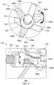
- Figure 2 (C) shows a cross-section of the deformable leg 126 in more detail.
- the section view of the deformable leg 126 shows the arrangement of the distal segment 126a and the proximal segment 126b, linked by the first line of weakening 136b.
- the distal segment 126a and the proximal segment 126b are displaced apart by an angle of 110 degrees, but other ranges are envisaged such as 80 to 140 degrees, for example.
- the angle formed between the proximal segment 126b and the body portion (i.e. the second attachment portion 127b) is 45 degrees, but other ranges are envisaged such as 30 to 60 degrees, for example.
- the angle formed at the second line of weakening 136a is 135 degrees but other angles are envisaged such as 100 to 170 degrees, for example.
- the deformable leg 126 illustrated in Figure 2 (C) has a uniform thickness throughout. It is envisaged that certain parts of the deformable leg 126 may have a width or a thickness that is less than others so as to promote more deformation in those areas.
- the first line of weakening 136b may have a smaller width and therefore a smaller cross-sectional area relative to the distal segment 126a and the proximal segment 126b.
- the second line of weakening 136a may have a smaller width or thickness and therefore a smaller cross-sectional area relative to the distal segment 126a.
- the length of the distal segment 126a and/or the proximal segment 126b may be a different length.
- the distal segment 126a and the proximal segment 126b may have a greater length, such as 12mm and 6.5mm respectively.
- the distal segment 126a and the proximal segment 126b may have a lesser length.
- the length of the distal segment 126a and the proximal segment 126b may be selected based on the desired deformation thereof. That is, the distance between the body portion and the expansion portion of the anchor 110 may be selected based on the desired extent of deformation of the expansion anchor 110 when it is expanded during use.
- Figure 3 (A) and Figure 3 (B) show the distal end of an expansion anchor 110 after expansion, where the expansion portion 122 is moved axially along the threaded shank towards the body portion of the anchor 110, to exert a force onto the deformable leg 126.
- the first attachment portion 127a and the second attachment portion 127b of the deformable leg 126 are circumferentially offset from one another.
- the proximal segment 126b and the distal segment 126a of the deformable leg 126 deform torsionally apart from one another and are urged radially outwards relative to the longitudinal axis of the expansion anchor 110.
- the distal segment 126a is urged towards the proximal side of the anchor 110. Since the first attachment portion 127a and the second attach portion 127b of the deformable leg 126 are circumferentially offset from one another, the distal segment 126a moves towards the proximal segment 126b at an angle offset from one another.
- the first line of weakening 136b urges outward which allows the deformable leg 126 to be radially offset and torsionally offset about the longitudinal axis of the expansion anchor 110.
- the proximal segment 126b and the distal segment 126a torsionally deform relative to one another about the first line of weakening 136b.
- the first line of weakening 136b provides a predetermined point of bending at which the deformable leg 126 deforms.
- three deformable legs 126 are provided circumferentially equidistantly spaced from one another.
- the body of the expansion anchor 110 has three expansion tabs 124 circumferentially equidistantly spaced from one another interjacent of the three deformable legs 126.
- any other suitable number of deformable legs 126 may be provided, such as two, or four, or five or six, for example.
- the number of deformable legs 126 may be selected based on the desired surface area or extent of engagement between the expansion anchor 110 and the surface in which the anchor 110 is fixed.
- the distal segment 126a and the proximal segment 126b torsionally deform such that the angle between them may be 60 degrees after expansion.
- Other angular offsets are also envisaged, such as 30 degrees, 45 degrees or 75 degrees, for example.
- Other smaller angular offsets are also envisaged, such as 2 degrees, 5 degrees, 10 degrees, 15 degrees, 20 degrees or 25 degrees, for example.
- adjacent deformable legs 126 may be placed such that adjacent legs 126 engage with one another to prevent further torsional deformation and/or further radial deformation about the longitudinal axis of the expansion anchor 110.
- the expansion tabs 124 are urged outward relative to the longitudinal axis of the expansion anchor 110.
- the proximal segment 126b is flush against the board in which the expansion anchor 110 is retained.
- the distal segment 126a is torsionally offset from the proximal segment 126b and also engages with the board. This increases the area of engagement between the deformable legs 126 and the surface in which the expansion anchor 110 is retained which increases the structural rigidity of the anchor into the wall.
- Figure 4 illustrates an alternative design that prevents the engagement of the deformable leg 226 with the tightening screw 230.
- a sleeve member in the form of a cylindrical sleeve 250 is provided towards the proximal end of the expansion anchor 210.
- the second line of the weakening 236a of the deformable leg 226 projects inward towards the tightening screw 230.
- the second line of weakening 236a of the deformable leg 236 engages directly with the sleeve member 250 to prevent it from engaging with the tightening screw 250.
- the sleeve member 250 is provided between the tightening screw 230 and the deformable leg 226 to protect the deformable leg 226 from engaging with the tightening screw 230, and thus damaging the screw thread.
- Figure 5 (A) and Figure 5 (B) illustrate an alternative embodiment for an expansion anchor 310 in which the first attachment portion 327a of the expansion anchor 310 comprises a recess 329 between a portion of the distal segment 326a and the expansion portion 322.
- the recess 329 or cut line may join up with the line of weakening 336a .
- the expansion portion 322 is provided with a ramping portion 323 (ramp surface) that, during expansion, engages with a disjointed part (i.e. separating the expansion portion and the distal segment 326a) of the first attachment portion 327a such that a direct engagement between the deformable leg 326 with the tightening screw is prevented.
- each deformable leg 326 is provided with a recess 329, and a portion of the expansion portion 322 is provided with a corresponding ramping portion 323 that receives a second line of weakening 336b, such that engagement of the deformable leg 326 onto the tightening screw is prevented.
- the ramping portions 323 move an end portion of the distal segment 326a away from the tightening screw during expansion.
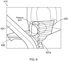
- Figure 6 illustrates such a pressure point projected towards the tightening screw 430 in the absence of the aforementioned ramping portion.
- the first attachment portion 427a i.e. the second line of weakening of the deformable leg 426
- the disjoined portion of the deformable leg 426 engages with the ramp instead of the tightening screw 430.
- Figure 7 shows another example of a sleeve 516 of an expansion anchor 510 in an open arrangement, showing the sleeve 516 in an unfolded state (sheet metal stamping configuration).
- the body 518 of the expansion anchor 510 has three expansion tabs 524 spaced equidistantly from one another.
- Deformable legs 526 are positioned between the expansion tabs 524. The design of the deformable legs 526 in this example limits torsion when the anchor 510 is expanded, as will be described below.
- a flange 532 is provided on a proximal side, having a first central aperture 542 configured to receive the shank of the tightening screw.
- a further flange 544 On a distal end, there is provided a further flange 544, having a second central aperture 546 (coaxial with the first central aperture 542) and which is threaded and configured for receiving the shank of the tightening screw.
- a greater width i.e. size measurement of the deformable leg 526 in a direction perpendicular to the longitudinal direction
- the distal segment 526a tapers outward such that the width of the distal segment 526a increases in the distal direction.
- the proximal segment 526b tapers outward such that the width of the proximal segment 526b increases in the proximal direction.
- more material is provided on the deformable leg 526 relative to the expansion tab 524 in order to increase the rigidity of the expansion anchor 510.
- the tightening screw may be provided with a tighter pitch to further limit torsional deformation.
- the proximal segment 526b is provided with a wider surface to increase the engagement contact with the wall in which the expansion anchor 510 is to be set. This further increases mechanical stability of the anchor 510 once is it set, and improves the structural performance of the anchor 510.
Landscapes
- Engineering & Computer Science (AREA)
- General Engineering & Computer Science (AREA)
- Mechanical Engineering (AREA)
- Dowels (AREA)
Abstract
Description
- The present invention relates to an expansion anchor, in particular, but not exclusively, to an expansion anchor suitable for use in the construction sector for anchoring, such as for a load to a wall and/or for a load to a top of a surface.
- There are two different types of expansion anchor currently known. A first type of expansion anchor consists of anchors made entirely of plastic, some of which are designed for anchoring to walls made of bricks with internal partitions defining internal cavities which are hollow or filled with low-density material, and/or walls made of a relatively friable or non-homogeneous materials, such as multi-layer walls, wall made of loose (i.e. not very compact) granular-concrete, and/or walls made of compact material and therefore having a high density, such as concrete walls or walls made of natural stone or solid bricks, or another high-density material.
- These plastic expansion anchors are used in a wide range of applications, but their use is limited to the anchoring of loads having a relatively low weight. Plastic expansion anchors are unable to anchor loads having medium duty weight.
- The second type of anchor differs from the plastic expansion anchor essentially in that it includes a tubular body made of metal. The tubular body typically comprises a metal conduit with an anchoring tab. The anchor having the metal tubular body further comprises a conical body and a tightening screw. The conical body is attached at the end of the tightening screw. When in use, the screw is tightened which causes the conical body to move axially inside of the conduit. Wedges of the conical body are gradually urged or otherwise driven radially outwards between the anchoring tabs, moving them apart towards the inside wall of the hole in which the anchor is placed. The anchoring tabs are moved apart until they are positioned into abutment against the inside surface (i.e. hole) of the wall, securing the anchor into the hole in the wall using friction and using mechanical locking.
- Metal anchors of this type are able to anchor loads to a greater extent compared to the plastic anchors. However, where there is a requirement to anchor even larger loads, even these types of anchors may not provide sufficient retention, capable of anchoring increased loads. Therefore, an anchor that is unable to provide the required retention may loosen or detach from the desired surface during use. Another problem associated with existing anchors is the lack of confirmation to a user that the anchor is completely, correctly, and securely fitted. Without such confirmation or indication to the user, a user may continue to tighten the anchor, causing overtightening of the anchor and/or damage to the surface in which the anchor is set. Yet, another problem associated with expansion anchors is the generation of pressure points from the expanding legs of the anchor that directly engage with the anchor screw thread. If the legs of the anchor expand in an uncontrolled manner, the contact between the legs of the anchor and the screw thread of the anchor causes damage to the anchor. In some instances, the damage is detrimental to the functioning of the anchor.
- Therefore, it would be desirable to provide an expansion anchor that can alleviate or mitigate one or more of the aforementioned problems. Particularly, it is an object of the invention to provide an expansion anchor with a higher retention force, or at least which can be used for a greater range of applications. It is also an object of the invention to provide an expansion anchor which is capable of anchoring loads having an even higher weight. It is a further object of the invention to provide an anchor with an improved user experience, indicating the complete, correct and secure fitting of an expansion anchor.
- The present invention provides at least an alternative to expansion anchors of the prior art.
- In accordance with the present invention there is provided an expansion anchor according to the appended claims.
- According to an aspect of the present invention, there is provided an expansion anchor comprising: a tubular sleeve having a longitudinal axis and comprising an expansion portion at a distal end and a body portion at a proximal end and expansion tabs attached to the body portion and extending towards the distal end; a tightening screw configured to move the expansion portion along the longitudinal axis inside the expansion tabs so as to expand the tabs radially outwardly relative to the longitudinal axis; at least one deformable leg extending between and attached to the body portion and to the expansion portion of the tubular sleeve, the deformable leg comprising at least two coupled segments, a distal segment, having a first attachment portion linking the distal segment to the expansion portion and a proximal segment, having a second attachment portion linking the proximal segment to the body portion, wherein the width of the proximal segment increases towards the proximal end of the tubular sleeve.
- Thus, the deformable leg is reinforced near the proximal end. This provides a wider surface area at the proximal end of the deformable leg, allowing an increased surface area to be in contact with the wall, which improves the mechanical performance of the expansion anchor and increases the load capacity of the expansion anchor. Moreover, this allows the deformation of the deformable legs to be controlled, so as to prevent a pressure point onto the tightening screw to be generated.
- Advantageously, in some embodiments, the first and second attachment portions may be circumferentially offset from each other about the longitudinal axis, so as to deform the deformable leg torsionally and radially outwardly relative to the longitudinal axis when moving the expansion portion from the distal end towards the proximal end. This is particularly beneficial because the proximal segment and the distal segment of the leg both engage with the surface to be engaged, in order to increase the surface area of engagement between the anchor and the surface.
- Thus, deformable leg(s) expand radially outwardly and torsionally to engage with the surface in which the anchor is set. The proximal segment and the distal segment of the leg both engage with the surface to increase the surface area of engagement between the anchor and the surface. This improves mechanical stability of the anchor in the wall, which increases the load capacity of the expansion anchor. Moreover, there is provided an indication to the user of a complete and secure setting in comparison with an anchor having legs that deform only radially outward, not least because the user will experience more friction when the legs deform and engage with the surface.
- Advantageously, in some embodiments, the width of the proximal segment may increase uniformly towards the proximal end.
- Advantageously, in some embodiments, the width of the distal segment may increase towards the distal end of the tubular sleeve.
- Advantageously, in some embodiments, the width of the distal segment may increase uniformly towards the distal end.
- Advantageously, in some embodiments, the expansion tabs may have a first rigidity, and the deformable legs may have a second rigidity greater than the first rigidity. By providing deformable legs that have a rigidity greater than that of the expansion tabs, the deformable of the deformable legs can be controlled to avoid the generation of pressure points on the tightening screw.
- Advantageously, in some embodiments, the at least one deformable leg may comprise a first line of weakening between the distal segment and the proximal segment, having a width less than the distal and proximal segments. This provides a predetermined point of deformable at which the distal and proximal segments move relative to one another.
- Advantageously, said first line of weakening may have a width less than said distal and proximal segments.
- Advantageously, said at least one deformable leg may comprise an outwardly facing second line of weakening provided between said first attachment portion and said distal segment. Preferably, said second line of weakening may be positioned proximal to said expansion portion. Even more preferably, said first attachment portion may further comprise a recess, arranged so as to continue from said second line of weakening and separating a portion of said distal segment from said expansion portion, and a ramped surface, configured to guidingly move said portion of said distal segment away from said longitudinal axis, during use.
- Advantageously, said expansion anchor may comprise at least two deformable legs arranged adjacent to one another, each one adapted to stoppingly engage at a predetermined deformation, so as to prevent additional torsional and radial deformation, during use. Preferably, said at least two deformable legs may be circumferentially equidistantly spaced about said longitudinal axis.
- Advantageously, said expansion anchor may further comprise a sleeve member coaxially arranged between said body portion and said tightening screw. Preferably, a distal end of said sleeve member may be adapted to operably engage with said expansion portion, so as to prevent contact between said tightening screw and said expansion portion moving from said distal end to said proximal end. Even more preferably, said sleeve member may be provided at said proximal end of said tubular sleeve.
- Embodiments of the invention are now described, by way of example only, hereinafter with reference to the accompanying drawings, in which:
-
Figure 1 illustrates an expansion anchor from: (A) a side view; and (B) a perspective side view; -
Figure 2 shows a distal end of an expansion anchor in (A) an end view and (B) a side view, and (C) a section view of a deformable leg; -
Figure 3 illustrates a close-up of a distal end of an expansion anchor from: (A) a perspective end view; and (B) a perspective side view; -
Figure 4 shows a perspective view of an expansion anchor; -
Figure 5 shows (A) a perspective view of a distal end of an expansion anchor; and (B) an open (i.e. unfolded) sleeve of an expansion anchor in a first configuration. -
Figure 6 illustrates a close up view of the expansion anchor distal end; and -
Figure 7 illustrates an open (i.e. unfolded) sleeve of an expansion anchor in a second configuration. - The described example embodiment relates to an expansion anchor and particularly to an expansion anchor for use in the construction sector. However, the invention is not necessarily restricted expansion anchors for use in the construction sector altogether but may also be used to secure a plurality of components together.
- Certain terminology is used in the following description for convenience only and is not limiting. The words 'right', 'left', 'lower', 'upper', 'front', 'rear', 'upward', 'down' and 'downward' designate directions in the drawings to which reference is made and are with respect to the described component when assembled and mounted. The words 'inner', 'inwardly' and 'outer', 'outwardly' refer to directions toward and away from, respectively, a designated centreline or a geometric centre of an element being described (e.g. central axis), the particular meaning being readily apparent from the context of the description.
- Further, as used herein, the terms 'connected', 'attached', 'coupled', 'mounted' are intended to include direct connections between two members without any other members interposed therebetween, as well as, indirect connections between members in which one or more other members are interposed therebetween. The terminology includes the words specifically mentioned above, derivatives thereof, and words of similar import.
- Further, unless otherwise specified, the use of ordinal adjectives, such as, "first", "second", "third" etc. merely indicate that different instances of like objects are being referred to and are not intended to imply that the objects so described must be in a given sequence, either temporally, spatially, in ranking or in any other manner.
- Like reference numerals are used to depict like features throughout.
-
Figure 1 (A) and Figure 1 (B) show an anchoring member, namely a mediumduty expansion anchor 110 that is suitable for insertion in an anchoring hole of a support or a wall. The meaning of light duty, medium duty and high duty are all common terms in the art and would be understood within the common general knowledge of the person skilled in the art. The expansion anchor 10 has aproximal end 112 and adistal end 114 and is structured such that it may be anchored or otherwise secured to a support or wall. It is preferable, though not essential, that theanchor 110 comprises a metal structure. It shall be understood that theanchor 110 may be secured to any wall structure. For example, the wall may be a solid structure or a non-solid structure. That is, the wall may be made from bricks, or the wall may be hollow, having defining spaces and/or a wall that is filled with a low-density material, or a non-compact wall such as a multi-layered wall or a wall made from a relatively friable material. The wall or structure may also be made from or filled with a material having a low compactness, or the wall may be made from a material of high density, such as, for example, concrete or natural stone or solid bricks. - The
expansion anchor 110 comprises asleeve 116 which, in this example, is tubular in shape and has alongitudinal axis 120. Theanchor 110 also comprises anexpansion portion 122 at thedistal end 114 which, in this example, is anexpansion nut 122. Theanchor 110 has a tighteningscrew 128 having a drive head and a threadedshank 130 projecting from the bottom of the drive head in the direction of thelongitudinal axis 120 towards thedistal end 114 of theanchor 110. The threadedshank 130 extends through an internal hole (not shown) of thesleeve 116. That is, the threadedshank 130 extends from the bottom of the drive head of the tighteningscrew 128, through to thedistal end 114 of the anchor. Theexpansion portion 122 has an internal thread which is designed to engage with the threadedshank 130, such that theexpansion portion 122 is moved axially along thelongitudinal axis 120 when rotated with a screwdriver or longitudinally expanded with an expansion tool. Theexpansion portion 122 is screwed onto thedistal end 114 of theshank 130. It is preferable that theexpansion portion 122 is frustoconical in shape, having a taper towards theproximal end 112 of theanchor 110. Alternatively, theexpansion portion 122 may be cylindrical in shape (e.g. having rounded edges). - The
sleeve 116 further comprises abody portion 118 at its proximal end.Expansion tabs 124 are attached to thebody portion 118 and extend in a direction away from thebody portion 118 towards thedistal end 114. In this particular example, theexpansion tabs 124 form an angle of 15 degrees with thelongitudinal axis 120. However, it is envisaged that theexpansion tabs 124 may form a different angle with thelongitudinal axis 120 such as for example, 10 degrees to 50 degrees. It is preferred that theexpansion tabs 124 have a free distal end portion (i.e. not connected to the expansion portion 122). - During use, the tightening
screw 128 is tightened and theexpansion portion 122 moves axially towards theproximal end 112 of theanchor 110. This axial movement of the threadedexpansion portion 122 urges the ends of theexpansion tabs 124 radially outward from thelongitudinal axis 120. In this example, eachexpansion tab 124 is provided with a number of gripping portions, namelyteeth 134 which, as will be explained, are capable of gripping a surface on which theexpansion tabs 124 engage. Asuitable flange 132 may be provided below the drive head of the tighteningscrew 128. Theflange 132 may be made from metal in this example and prevents the tighteningscrew 128 from sinking into the wall or surface that theanchor 110 is to be attached to. This will be made clearer with reference to the subsequent drawings. - The
anchor 110 is further provided withdeformable legs 126, circumferentially arranged about thesleeve 116. Each one of thelegs 126 extend between thebody portion 118 and theexpansion portion 122 of thesleeve 116 and are attached thereto. Thus, when theexpansion portion 122 moves axially along thelongitudinal axis 120 towards the body portion 118 (i.e. towards the proximal end 112), a pushing force is exerted onto thelegs 126 from thedistal end 114. - Referring now to
Figures 2 (A), (B) and(C) , a close-up of thedistal end 114 of an embodiment of theexpansion anchor 110 is shown. Here, theexpansion anchor 110 shown has a deformable leg in between the body portion and theexpansion portion 122. The deformable leg is formed from adistal segment 126a on the distal side of theexpansion anchor 110, and aproximal segment 126b on the proximal side of theexpansion anchor 110. Thedistal segment 126a and theproximal segment 126b are coupled together. Afirst attachment portion 127a links thedistal segment 126a to theexpansion portion 122. Asecond attachment portion 127b links theproximal segment 126b to the body portion. Thefirst attachment portion 127a and thesecond attachment portion 127b are circumferentially offset from one another about the longitudinal axis of theexpansion anchor 110. Thefirst attachment portion 127a and thesecond attachment portion 127b are circumferentially offset from one another about the longitudinal axis of theexpansion anchor 110. In this example, a first line ofweakening 136b is provided between thedistal segment 126a and theproximal segment 126b, having a smaller cross-sectional area in comparison to thesegments weakening 136b is provided inwardly facing (i.e. radially inwardly facing). A second line ofweakening 136a is provided on thefirst attachment portion 127a, . The second line ofweakening 136a is provided outwardly facing (i.e. radially outwardly facing). The first line ofweakening 136b and the second line ofweakening 136a are opposingly facing. The lines ofweakening deformable legs 126, along selected areas of thelegs 126. The first line of weakening 136b acts as a living hinge, integrally formed with and linking thedistal segment 126a and theproximal segment 126b. The first line ofweakening 136b, in this way, allows thedistal segment 126a and theproximal segment 126b to bend relative to one another about the first line ofweakening 136b. Since the first line ofweakening 136b is inwardly facing, the axial movement of the threadedexpansion portion 122 exerts a pushing force onto the distal end of thedeformable leg 126, and urges thedeformable leg 126 radially outward (i.e. in a direction opposite the inwardly facing first line ofweakening 136b), such that the first line of weakening 136b folds outward to bend thedistal segment 126a and theproximal segment 126b relative to one another. In substantially the same way, the second line ofweakening 136a acts as a living hinge, integrally formed with and linking thefirst attachment portion 127a and thedistal segment 126a. When the first line of weakening 136b folds outward, the outwardly facing second line ofweakening 136a folds inwards (i.e. in a direction opposite the outwardly facing second line ofweakening 136a), since the first line ofweakening 136b and the second line ofweakening 136a face opposite directions. The first line ofweakening 136b has a width (i.e. size measurement of the deformable leg in a direction perpendicular to the longitudinal direction) that is small relative to the width of thedistal segment 126a and theproximal segment 126b. The smaller width of the first line of weakening 136b relative to thedistal segment 126a andproximal segment 126b provides a reduced cross-sectional area. -
Figure 2 (C) shows a cross-section of thedeformable leg 126 in more detail. The section view of thedeformable leg 126 shows the arrangement of thedistal segment 126a and theproximal segment 126b, linked by the first line ofweakening 136b. In this example, thedistal segment 126a and theproximal segment 126b are displaced apart by an angle of 110 degrees, but other ranges are envisaged such as 80 to 140 degrees, for example. The angle formed between theproximal segment 126b and the body portion (i.e. thesecond attachment portion 127b) is 45 degrees, but other ranges are envisaged such as 30 to 60 degrees, for example. The angle formed at the second line ofweakening 136a is 135 degrees but other angles are envisaged such as 100 to 170 degrees, for example. Thedeformable leg 126 illustrated inFigure 2 (C) has a uniform thickness throughout. It is envisaged that certain parts of thedeformable leg 126 may have a width or a thickness that is less than others so as to promote more deformation in those areas. For example, the first line ofweakening 136b may have a smaller width and therefore a smaller cross-sectional area relative to thedistal segment 126a and theproximal segment 126b. The second line ofweakening 136a may have a smaller width or thickness and therefore a smaller cross-sectional area relative to thedistal segment 126a. In some examples, the length of thedistal segment 126a and/or theproximal segment 126b may be a different length. For example, thedistal segment 126a and theproximal segment 126b may have a greater length, such as 12mm and 6.5mm respectively. Alternatively, thedistal segment 126a and theproximal segment 126b may have a lesser length. The length of thedistal segment 126a and theproximal segment 126b may be selected based on the desired deformation thereof. That is, the distance between the body portion and the expansion portion of theanchor 110 may be selected based on the desired extent of deformation of theexpansion anchor 110 when it is expanded during use. -
Figure 3 (A) and Figure 3 (B) show the distal end of anexpansion anchor 110 after expansion, where theexpansion portion 122 is moved axially along the threaded shank towards the body portion of theanchor 110, to exert a force onto thedeformable leg 126. Thefirst attachment portion 127a and thesecond attachment portion 127b of thedeformable leg 126 are circumferentially offset from one another. As thedeformable legs 126 are urged outward, theproximal segment 126b and thedistal segment 126a of thedeformable leg 126 deform torsionally apart from one another and are urged radially outwards relative to the longitudinal axis of theexpansion anchor 110. More specifically, as theexpansion portion 122 moves towards the body portion of theanchor 110, thedistal segment 126a is urged towards the proximal side of theanchor 110. Since thefirst attachment portion 127a and the second attachportion 127b of thedeformable leg 126 are circumferentially offset from one another, thedistal segment 126a moves towards theproximal segment 126b at an angle offset from one another. The first line ofweakening 136b urges outward which allows thedeformable leg 126 to be radially offset and torsionally offset about the longitudinal axis of theexpansion anchor 110. Theproximal segment 126b and thedistal segment 126a torsionally deform relative to one another about the first line ofweakening 136b. The first line ofweakening 136b provides a predetermined point of bending at which thedeformable leg 126 deforms. In this example, threedeformable legs 126 are provided circumferentially equidistantly spaced from one another. The body of theexpansion anchor 110 has threeexpansion tabs 124 circumferentially equidistantly spaced from one another interjacent of the threedeformable legs 126. In other examples, however, it is also envisaged that any other suitable number ofdeformable legs 126 may be provided, such as two, or four, or five or six, for example. The number ofdeformable legs 126 may be selected based on the desired surface area or extent of engagement between theexpansion anchor 110 and the surface in which theanchor 110 is fixed. - In this particular example, the
distal segment 126a and theproximal segment 126b torsionally deform such that the angle between them may be 60 degrees after expansion. Other angular offsets are also envisaged, such as 30 degrees, 45 degrees or 75 degrees, for example. Other smaller angular offsets are also envisaged, such as 2 degrees, 5 degrees, 10 degrees, 15 degrees, 20 degrees or 25 degrees, for example. At a predetermined angular offset, adjacentdeformable legs 126 may be placed such thatadjacent legs 126 engage with one another to prevent further torsional deformation and/or further radial deformation about the longitudinal axis of theexpansion anchor 110. As thesegments deformable leg 126 deform torsionally and radially outward, theexpansion tabs 124 are urged outward relative to the longitudinal axis of theexpansion anchor 110. After expansion, theproximal segment 126b is flush against the board in which theexpansion anchor 110 is retained. In some examples, thedistal segment 126a is torsionally offset from theproximal segment 126b and also engages with the board. This increases the area of engagement between thedeformable legs 126 and the surface in which theexpansion anchor 110 is retained which increases the structural rigidity of the anchor into the wall. -
Figure 4 illustrates an alternative design that prevents the engagement of thedeformable leg 226 with the tighteningscrew 230. In this example, a sleeve member in the form of acylindrical sleeve 250 is provided towards the proximal end of theexpansion anchor 210. When theexpansion portion 222 moves from the distal end of theexpansion anchor 210 towards the proximal end, thedeformable leg 226 deforms in the way previously described. The second line of theweakening 236a of thedeformable leg 226 projects inward towards the tighteningscrew 230. However, the second line of weakening 236a of the deformable leg 236 engages directly with thesleeve member 250 to prevent it from engaging with the tighteningscrew 250. Thesleeve member 250 is provided between the tighteningscrew 230 and thedeformable leg 226 to protect thedeformable leg 226 from engaging with the tighteningscrew 230, and thus damaging the screw thread. -
Figure 5 (A) and Figure 5 (B) illustrate an alternative embodiment for anexpansion anchor 310 in which thefirst attachment portion 327a of theexpansion anchor 310 comprises arecess 329 between a portion of thedistal segment 326a and theexpansion portion 322. Therecess 329 or cut line may join up with the line ofweakening 336a . Theexpansion portion 322 is provided with a ramping portion 323 (ramp surface) that, during expansion, engages with a disjointed part (i.e. separating the expansion portion and thedistal segment 326a) of thefirst attachment portion 327a such that a direct engagement between the deformable leg 326 with the tightening screw is prevented. The engagement directly with the tightening screw is prevented by moving the end portion of thedistal segment 326a away from the tightening screw, preventing a pressure point from being formed. Referring particularly toFigure 4 (B) , each deformable leg 326 is provided with arecess 329, and a portion of theexpansion portion 322 is provided with a corresponding rampingportion 323 that receives a second line ofweakening 336b, such that engagement of the deformable leg 326 onto the tightening screw is prevented. The rampingportions 323 move an end portion of thedistal segment 326a away from the tightening screw during expansion. -
Figure 6 illustrates such a pressure point projected towards the tighteningscrew 430 in the absence of the aforementioned ramping portion. As thedeformable legs 426 expand outward of the longitudinal axis, thefirst attachment portion 427a (i.e. the second line of weakening of the deformable leg 426) projects inward towards the tighteningscrew 430 to counteract a radial and torsional movement of the first line of weakening of thedeformable leg 426. By provided a ramp on the expansion portion, the disjoined portion of thedeformable leg 426 engages with the ramp instead of the tighteningscrew 430. -
Figure 7 shows another example of asleeve 516 of anexpansion anchor 510 in an open arrangement, showing thesleeve 516 in an unfolded state (sheet metal stamping configuration). Thebody 518 of theexpansion anchor 510 has threeexpansion tabs 524 spaced equidistantly from one another.Deformable legs 526 are positioned between theexpansion tabs 524. The design of thedeformable legs 526 in this example limits torsion when theanchor 510 is expanded, as will be described below. Aflange 532 is provided on a proximal side, having a firstcentral aperture 542 configured to receive the shank of the tightening screw. On a distal end, there is provided afurther flange 544, having a second central aperture 546 (coaxial with the first central aperture 542) and which is threaded and configured for receiving the shank of the tightening screw. A greater width (i.e. size measurement of thedeformable leg 526 in a direction perpendicular to the longitudinal direction) is provided outward of the second line ofweakening 536a in a tapered manner. That is, from the second line ofweakening 536a towards the distal end, thedistal segment 526a tapers outward such that the width of thedistal segment 526a increases in the distal direction. From the second line ofweakening 536a towards the proximal end, theproximal segment 526b tapers outward such that the width of theproximal segment 526b increases in the proximal direction. In this particular example, more material is provided on thedeformable leg 526 relative to theexpansion tab 524 in order to increase the rigidity of theexpansion anchor 510. Thus, when theexpansion anchor 510 expands (i.e. when the expansion portion moves from the distal end towards the proximal end), the torsional deformation of thelegs 526 are limited (minimised). Though not shown, the tightening screw may be provided with a tighter pitch to further limit torsional deformation. At the proximal end of thedeformable leg 526, theproximal segment 526b is provided with a wider surface to increase the engagement contact with the wall in which theexpansion anchor 510 is to be set. This further increases mechanical stability of theanchor 510 once is it set, and improves the structural performance of theanchor 510. - Through the description and claims of this specification, the words "comprise" and "contain" and variations of them mean "including but not limited to", and they are not intended to (and do not) exclude other moieties, additives, components, integers or steps. Throughout the description and claims of this specification, the singular encompasses the plural unless the context otherwise requires. In particular, where the indefinite article is used, the specification is to be understood as contemplating plurality as well as singularity, unless the context requires otherwise.
- Features, integers, characteristics, compounds, chemical moieties or groups described in conjunction with a particular aspect, embodiment or example of the invention are to be understood to be applicable to any other aspect, embodiment or example described herein unless incompatible therewith. All of the features disclosed in this specification (including any accompanying claims, abstract and drawings), and/or all of the steps of any method or process so disclosed, may be combined in any combination, except combinations where at least some of such features and/or steps are mutually exclusive. The invention is not restricted to the details of any foregoing embodiments. The invention extends to any novel one, or any novel combination, of the features disclosed in this specification (including any accompanying claims, abstract or drawings), or to any novel one, or any novel combination, of the steps of any method or process so disclosed.
- It will be appreciated by persons skilled in the art that the above embodiment(s) have been described by way of example only and not in any limitative sense, and that various alterations and modifications are possible without departing from the scope of the invention as defined by the appended claims. Various modifications to the detailed designs as described above are possible.
Claims (15)
- An expansion anchor comprising:a tubular sleeve having a longitudinal axis and comprising an expansion portion at a distal end and a body portion at a proximal end and expansion tabs attached to said body portion and extending towards said distal end;a tightening screw configured to move said expansion portion along said longitudinal axis inside said expansion tabs so as to expand said tabs radially outwardly relative to said longitudinal axis; andat least one deformable leg extending between and attached to said body portion and to said expansion portion of said tubular sleeve, said deformable leg comprising at least two coupled segments, a distal segment, having a first attachment portion linking said distal segment to said expansion portion and a proximal segment, having a second attachment portion linking said proximal segment to said body portion,wherein the width of said proximal segment increases towards said proximal end of said tubular sleeve.
- An expansion anchor according to claim 1, wherein said first and second attachment portions are circumferentially offset from each other about said longitudinal axis, so as to deform said deformable leg torsionally and radially outwardly relative to said longitudinal axis when moving said expansion portion from said distal end towards said proximal end.
- An expansion anchor according to any one of claim 1 and claim 2, wherein said width of said proximal segment increases uniformly towards said proximal end.
- An expansion anchor according to any one of the preceding claims, wherein the width of said distal segment increases towards said distal end of said tubular sleeve.
- An expansion anchor according to any one of the preceding claims, wherein said expansion tabs have a first rigidity, and said deformable legs have a second rigidity greater than said first rigidity.
- An expansion anchor according to any one of the preceding claims, wherein said at least one deformable leg comprises a first line of weakening between said distal segment and said proximal segment, having a width less than said distal and proximal segments.
- An expansion anchor according to claim 6, wherein said first line of weakening has a width less than said distal and proximal segments.
- An expansion anchor according to anyone of the preceding claims, wherein said at least one deformable leg comprises an outwardly facing second line of weakening provided between said first attachment portion and said distal segment.
- An expansion anchor according to claim 8, wherein said second line of weakening is positioned proximal to said expansion portion.
- An expansion anchor according to any one of claims 8 and 9, wherein said first attachment portion further comprises a recess, arranged so as to continue from said second line of weakening and separating a portion of said distal segment from said expansion portion, and a ramped surface, configured to guidingly move said portion of said distal segment away from said longitudinal axis, during use.
- An expansion anchor according to any one of the preceding claims, comprising at least two deformable legs arranged adjacent to one another, each one adapted to stoppingly engage at a predetermined deformation, so as to prevent additional torsional and radial deformation, during use.
- An expansion anchor according to claim 11, wherein said at least two deformable legs are circumferentially equidistantly spaced about said longitudinal axis.
- An expansion anchor according to any one of the preceding claims, further comprising a sleeve member coaxially arranged between said body portion and said tightening screw.
- An expansion anchor according to claim 13, wherein a distal end of said sleeve member is adapted to operably engage with said expansion portion, so as to prevent contact between said tightening screw and said expansion portion moving from said distal end to said proximal end.
- An expansion anchor according to any one of claims 13 and 14, wherein said sleeve member is provided at said proximal end of said tubular sleeve.
Priority Applications (1)
| Application Number | Priority Date | Filing Date | Title |
|---|---|---|---|
| AU2021209166A AU2021209166A1 (en) | 2020-08-14 | 2021-07-26 | Improved expansion anchor |
Applications Claiming Priority (2)
| Application Number | Priority Date | Filing Date | Title |
|---|---|---|---|
| EP20191109 | 2020-08-14 | ||
| EP20191102 | 2020-08-14 |
Publications (3)
| Publication Number | Publication Date |
|---|---|
| EP3954910A1 true EP3954910A1 (en) | 2022-02-16 |
| EP3954910A3 EP3954910A3 (en) | 2022-08-10 |
| EP3954910B1 EP3954910B1 (en) | 2025-07-30 |
Family
ID=75787027
Family Applications (1)
| Application Number | Title | Priority Date | Filing Date |
|---|---|---|---|
| EP21173262.3A Active EP3954910B1 (en) | 2020-08-14 | 2021-05-11 | Improved expansion anchor |
Country Status (2)
| Country | Link |
|---|---|
| EP (1) | EP3954910B1 (en) |
| AU (1) | AU2021209166A1 (en) |
Cited By (1)
| Publication number | Priority date | Publication date | Assignee | Title |
|---|---|---|---|---|
| EP4421332B1 (en) | 2023-02-21 | 2025-09-10 | fischerwerke GmbH & Co. KG | Plastic dowel |
Citations (5)
| Publication number | Priority date | Publication date | Assignee | Title |
|---|---|---|---|---|
| US4182217A (en) * | 1975-12-23 | 1980-01-08 | Albert Berner | Straddling dowel construction |
| US6719509B1 (en) * | 2002-10-04 | 2004-04-13 | Joker Ind Co Ltd | Expansion screw |
| EP1338803B1 (en) * | 2002-02-21 | 2005-05-25 | Black & Decker Inc. | Fixing plug for a screw |
| US20120195707A1 (en) * | 2011-01-10 | 2012-08-02 | Black & Decker Inc. | Wall Anchor For a Screw |
| EP3825561A1 (en) * | 2019-11-19 | 2021-05-26 | Illinois Tool Works, Inc. | Expansion anchor |
Family Cites Families (1)
| Publication number | Priority date | Publication date | Assignee | Title |
|---|---|---|---|---|
| FR2611005B1 (en) * | 1987-02-16 | 1989-06-23 | Bolivia Chevilles Bol Ets L | PLASTIC EXPANSION ANKLE |
-
2021
- 2021-05-11 EP EP21173262.3A patent/EP3954910B1/en active Active
- 2021-07-26 AU AU2021209166A patent/AU2021209166A1/en active Pending
Patent Citations (5)
| Publication number | Priority date | Publication date | Assignee | Title |
|---|---|---|---|---|
| US4182217A (en) * | 1975-12-23 | 1980-01-08 | Albert Berner | Straddling dowel construction |
| EP1338803B1 (en) * | 2002-02-21 | 2005-05-25 | Black & Decker Inc. | Fixing plug for a screw |
| US6719509B1 (en) * | 2002-10-04 | 2004-04-13 | Joker Ind Co Ltd | Expansion screw |
| US20120195707A1 (en) * | 2011-01-10 | 2012-08-02 | Black & Decker Inc. | Wall Anchor For a Screw |
| EP3825561A1 (en) * | 2019-11-19 | 2021-05-26 | Illinois Tool Works, Inc. | Expansion anchor |
Cited By (1)
| Publication number | Priority date | Publication date | Assignee | Title |
|---|---|---|---|---|
| EP4421332B1 (en) | 2023-02-21 | 2025-09-10 | fischerwerke GmbH & Co. KG | Plastic dowel |
Also Published As
| Publication number | Publication date |
|---|---|
| EP3954910B1 (en) | 2025-07-30 |
| AU2021209166A1 (en) | 2022-03-03 |
| EP3954910A3 (en) | 2022-08-10 |
Similar Documents
| Publication | Publication Date | Title |
|---|---|---|
| JP4804757B2 (en) | Osteosynthesis device | |
| JP4796278B2 (en) | Expandable collet anchor device, its components and methods for making and using the same | |
| JP2860299B2 (en) | fastener | |
| JP4510032B2 (en) | Non-expandable medical implant closure with multi-surface removal aperture | |
| US12419668B2 (en) | Rod coupling assemblies for bone stabilization constructs | |
| EP3682828B1 (en) | Uni-planar bone fixation assembly | |
| US20210177183A1 (en) | Dual-Mounted End Cap System And Locking System For An Adjustable Rod | |
| US5816012A (en) | Dual threaded fastener and metal component assembly | |
| KR20070026472A (en) | Extraction screw driver | |
| JP2009516569A (en) | Reverse angle screw configuration with separation prevention function | |
| US20240183373A1 (en) | Connection between two components with tolerance compensation and a connecting method therefor | |
| US20170020573A1 (en) | Pedicle screw tulip assembly with multi-segmented member | |
| CA2801376C (en) | Externally splined fastener | |
| CN101395388A (en) | friction clamp | |
| JP2004251450A (en) | Transplanting device with threaded lock mechanism | |
| US10495131B2 (en) | Blind nut, a blind nut assembly and mounting structure thereof | |
| AU2004201507B2 (en) | Screw anchor | |
| EP3954910B1 (en) | Improved expansion anchor | |
| EP3825561A1 (en) | Expansion anchor | |
| JP7290214B2 (en) | Adjustable fixed support member and support structure | |
| JP7315997B2 (en) | support structure | |
| US20030185647A1 (en) | Fastener/deflectable retaining ring assembly | |
| JP7315996B2 (en) | support structure | |
| US11680598B2 (en) | Fixing device | |
| JP2021177059A (en) | Rod and cylinder |
Legal Events
| Date | Code | Title | Description |
|---|---|---|---|
| PUAI | Public reference made under article 153(3) epc to a published international application that has entered the european phase |
Free format text: ORIGINAL CODE: 0009012 |
|
| STAA | Information on the status of an ep patent application or granted ep patent |
Free format text: STATUS: THE APPLICATION HAS BEEN PUBLISHED |
|
| AK | Designated contracting states |
Kind code of ref document: A1 Designated state(s): AL AT BE BG CH CY CZ DE DK EE ES FI FR GB GR HR HU IE IS IT LI LT LU LV MC MK MT NL NO PL PT RO RS SE SI SK SM TR |
|
| PUAB | Information related to the publication of an a document modified or deleted |
Free format text: ORIGINAL CODE: 0009199EPPU |
|
| PUAF | Information related to the publication of a search report (a3 document) modified or deleted |
Free format text: ORIGINAL CODE: 0009199SEPU |
|
| PUAL | Search report despatched |
Free format text: ORIGINAL CODE: 0009013 |
|
| D17D | Deferred search report published (deleted) | ||
| AK | Designated contracting states |
Kind code of ref document: A3 Designated state(s): AL AT BE BG CH CY CZ DE DK EE ES FI FR GB GR HR HU IE IS IT LI LT LU LV MC MK MT NL NO PL PT RO RS SE SI SK SM TR |
|
| RIC1 | Information provided on ipc code assigned before grant |
Ipc: F16B 13/12 20060101ALI20220705BHEP Ipc: F16B 13/04 20060101ALI20220705BHEP Ipc: F16B 13/06 20060101ALI20220705BHEP Ipc: F16B 13/08 20060101AFI20220705BHEP |
|
| STAA | Information on the status of an ep patent application or granted ep patent |
Free format text: STATUS: REQUEST FOR EXAMINATION WAS MADE |
|
| 17P | Request for examination filed |
Effective date: 20220804 |
|
| RBV | Designated contracting states (corrected) |
Designated state(s): AL AT BE BG CH CY CZ DE DK EE ES FI FR GB GR HR HU IE IS IT LI LT LU LV MC MK MT NL NO PL PT RO RS SE SI SK SM TR |
|
| STAA | Information on the status of an ep patent application or granted ep patent |
Free format text: STATUS: EXAMINATION IS IN PROGRESS |
|
| 17Q | First examination report despatched |
Effective date: 20231025 |
|
| GRAP | Despatch of communication of intention to grant a patent |
Free format text: ORIGINAL CODE: EPIDOSNIGR1 |
|
| STAA | Information on the status of an ep patent application or granted ep patent |
Free format text: STATUS: GRANT OF PATENT IS INTENDED |
|
| INTG | Intention to grant announced |
Effective date: 20250317 |
|
| RIN1 | Information on inventor provided before grant (corrected) |
Inventor name: MARASCO, JEAN-PAUL Inventor name: COUVREUR, JEROME |
|
| P01 | Opt-out of the competence of the unified patent court (upc) registered |
Free format text: CASE NUMBER: APP_16392/2025 Effective date: 20250403 |
|
| GRAS | Grant fee paid |
Free format text: ORIGINAL CODE: EPIDOSNIGR3 |
|
| GRAA | (expected) grant |
Free format text: ORIGINAL CODE: 0009210 |
|
| STAA | Information on the status of an ep patent application or granted ep patent |
Free format text: STATUS: THE PATENT HAS BEEN GRANTED |
|
| AK | Designated contracting states |
Kind code of ref document: B1 Designated state(s): AL AT BE BG CH CY CZ DE DK EE ES FI FR GB GR HR HU IE IS IT LI LT LU LV MC MK MT NL NO PL PT RO RS SE SI SK SM TR |
|
| REG | Reference to a national code |
Ref country code: GB Ref legal event code: FG4D |
|
| REG | Reference to a national code |
Ref country code: CH Ref legal event code: EP |
|
| REG | Reference to a national code |
Ref country code: DE Ref legal event code: R096 Ref document number: 602021034928 Country of ref document: DE |
|
| REG | Reference to a national code |
Ref country code: IE Ref legal event code: FG4D |
|
| REG | Reference to a national code |
Ref country code: NL Ref legal event code: MP Effective date: 20250730 |
|
| REG | Reference to a national code |
Ref country code: AT Ref legal event code: MK05 Ref document number: 1819201 Country of ref document: AT Kind code of ref document: T Effective date: 20250730 |
|
| PG25 | Lapsed in a contracting state [announced via postgrant information from national office to epo] |
Ref country code: PT Free format text: LAPSE BECAUSE OF FAILURE TO SUBMIT A TRANSLATION OF THE DESCRIPTION OR TO PAY THE FEE WITHIN THE PRESCRIBED TIME-LIMIT Effective date: 20251202 |
|
| PG25 | Lapsed in a contracting state [announced via postgrant information from national office to epo] |
Ref country code: IS Free format text: LAPSE BECAUSE OF FAILURE TO SUBMIT A TRANSLATION OF THE DESCRIPTION OR TO PAY THE FEE WITHIN THE PRESCRIBED TIME-LIMIT Effective date: 20251130 |
|
| PG25 | Lapsed in a contracting state [announced via postgrant information from national office to epo] |
Ref country code: NO Free format text: LAPSE BECAUSE OF FAILURE TO SUBMIT A TRANSLATION OF THE DESCRIPTION OR TO PAY THE FEE WITHIN THE PRESCRIBED TIME-LIMIT Effective date: 20251030 |
|
| REG | Reference to a national code |
Ref country code: LT Ref legal event code: MG9D |
|
| PG25 | Lapsed in a contracting state [announced via postgrant information from national office to epo] |
Ref country code: AT Free format text: LAPSE BECAUSE OF FAILURE TO SUBMIT A TRANSLATION OF THE DESCRIPTION OR TO PAY THE FEE WITHIN THE PRESCRIBED TIME-LIMIT Effective date: 20250730 |
|
| PG25 | Lapsed in a contracting state [announced via postgrant information from national office to epo] |
Ref country code: FI Free format text: LAPSE BECAUSE OF FAILURE TO SUBMIT A TRANSLATION OF THE DESCRIPTION OR TO PAY THE FEE WITHIN THE PRESCRIBED TIME-LIMIT Effective date: 20250730 |
|
| PG25 | Lapsed in a contracting state [announced via postgrant information from national office to epo] |
Ref country code: HR Free format text: LAPSE BECAUSE OF FAILURE TO SUBMIT A TRANSLATION OF THE DESCRIPTION OR TO PAY THE FEE WITHIN THE PRESCRIBED TIME-LIMIT Effective date: 20250730 Ref country code: NL Free format text: LAPSE BECAUSE OF FAILURE TO SUBMIT A TRANSLATION OF THE DESCRIPTION OR TO PAY THE FEE WITHIN THE PRESCRIBED TIME-LIMIT Effective date: 20250730 |
|
| PG25 | Lapsed in a contracting state [announced via postgrant information from national office to epo] |
Ref country code: GR Free format text: LAPSE BECAUSE OF FAILURE TO SUBMIT A TRANSLATION OF THE DESCRIPTION OR TO PAY THE FEE WITHIN THE PRESCRIBED TIME-LIMIT Effective date: 20251031 |
|
| PG25 | Lapsed in a contracting state [announced via postgrant information from national office to epo] |
Ref country code: SE Free format text: LAPSE BECAUSE OF FAILURE TO SUBMIT A TRANSLATION OF THE DESCRIPTION OR TO PAY THE FEE WITHIN THE PRESCRIBED TIME-LIMIT Effective date: 20250730 |
|
| PG25 | Lapsed in a contracting state [announced via postgrant information from national office to epo] |
Ref country code: LV Free format text: LAPSE BECAUSE OF FAILURE TO SUBMIT A TRANSLATION OF THE DESCRIPTION OR TO PAY THE FEE WITHIN THE PRESCRIBED TIME-LIMIT Effective date: 20250730 |
|
| PG25 | Lapsed in a contracting state [announced via postgrant information from national office to epo] |
Ref country code: PL Free format text: LAPSE BECAUSE OF FAILURE TO SUBMIT A TRANSLATION OF THE DESCRIPTION OR TO PAY THE FEE WITHIN THE PRESCRIBED TIME-LIMIT Effective date: 20250730 Ref country code: BG Free format text: LAPSE BECAUSE OF FAILURE TO SUBMIT A TRANSLATION OF THE DESCRIPTION OR TO PAY THE FEE WITHIN THE PRESCRIBED TIME-LIMIT Effective date: 20250730 |
|
| PG25 | Lapsed in a contracting state [announced via postgrant information from national office to epo] |
Ref country code: RS Free format text: LAPSE BECAUSE OF FAILURE TO SUBMIT A TRANSLATION OF THE DESCRIPTION OR TO PAY THE FEE WITHIN THE PRESCRIBED TIME-LIMIT Effective date: 20251030 |
|
| PG25 | Lapsed in a contracting state [announced via postgrant information from national office to epo] |
Ref country code: ES Free format text: LAPSE BECAUSE OF FAILURE TO SUBMIT A TRANSLATION OF THE DESCRIPTION OR TO PAY THE FEE WITHIN THE PRESCRIBED TIME-LIMIT Effective date: 20250730 |
|
| PG25 | Lapsed in a contracting state [announced via postgrant information from national office to epo] |
Ref country code: SM Free format text: LAPSE BECAUSE OF FAILURE TO SUBMIT A TRANSLATION OF THE DESCRIPTION OR TO PAY THE FEE WITHIN THE PRESCRIBED TIME-LIMIT Effective date: 20250730 |
|
| PG25 | Lapsed in a contracting state [announced via postgrant information from national office to epo] |
Ref country code: DK Free format text: LAPSE BECAUSE OF FAILURE TO SUBMIT A TRANSLATION OF THE DESCRIPTION OR TO PAY THE FEE WITHIN THE PRESCRIBED TIME-LIMIT Effective date: 20250730 |
|
| PG25 | Lapsed in a contracting state [announced via postgrant information from national office to epo] |
Ref country code: CZ Free format text: LAPSE BECAUSE OF FAILURE TO SUBMIT A TRANSLATION OF THE DESCRIPTION OR TO PAY THE FEE WITHIN THE PRESCRIBED TIME-LIMIT Effective date: 20250730 |
|
| PG25 | Lapsed in a contracting state [announced via postgrant information from national office to epo] |
Ref country code: EE Free format text: LAPSE BECAUSE OF FAILURE TO SUBMIT A TRANSLATION OF THE DESCRIPTION OR TO PAY THE FEE WITHIN THE PRESCRIBED TIME-LIMIT Effective date: 20250730 Ref country code: SK Free format text: LAPSE BECAUSE OF FAILURE TO SUBMIT A TRANSLATION OF THE DESCRIPTION OR TO PAY THE FEE WITHIN THE PRESCRIBED TIME-LIMIT Effective date: 20250730 |