EP3954903A1 - Electric blower, electric vacuum cleaner, and hand dryer - Google Patents
Electric blower, electric vacuum cleaner, and hand dryer Download PDFInfo
- Publication number
- EP3954903A1 EP3954903A1 EP19924345.2A EP19924345A EP3954903A1 EP 3954903 A1 EP3954903 A1 EP 3954903A1 EP 19924345 A EP19924345 A EP 19924345A EP 3954903 A1 EP3954903 A1 EP 3954903A1
- Authority
- EP
- European Patent Office
- Prior art keywords
- electric blower
- substrate
- motor
- battery
- disposed
- Prior art date
- Legal status (The legal status is an assumption and is not a legal conclusion. Google has not performed a legal analysis and makes no representation as to the accuracy of the status listed.)
- Withdrawn
Links
Images



Classifications
-
- F—MECHANICAL ENGINEERING; LIGHTING; HEATING; WEAPONS; BLASTING
- F04—POSITIVE - DISPLACEMENT MACHINES FOR LIQUIDS; PUMPS FOR LIQUIDS OR ELASTIC FLUIDS
- F04D—NON-POSITIVE-DISPLACEMENT PUMPS
- F04D19/00—Axial-flow pumps
- F04D19/002—Axial flow fans
-
- A—HUMAN NECESSITIES
- A47—FURNITURE; DOMESTIC ARTICLES OR APPLIANCES; COFFEE MILLS; SPICE MILLS; SUCTION CLEANERS IN GENERAL
- A47K—SANITARY EQUIPMENT; ACCESSORIES THEREFOR, e.g. TOILET ACCESSORIES
- A47K10/00—Body-drying implements; Toilet paper; Holders therefor
- A47K10/48—Drying by means of hot air
-
- A—HUMAN NECESSITIES
- A47—FURNITURE; DOMESTIC ARTICLES OR APPLIANCES; COFFEE MILLS; SPICE MILLS; SUCTION CLEANERS IN GENERAL
- A47L—DOMESTIC WASHING OR CLEANING; SUCTION CLEANERS IN GENERAL
- A47L5/00—Structural features of suction cleaners
- A47L5/12—Structural features of suction cleaners with power-driven air-pumps or air-compressors, e.g. driven by motor vehicle engine vacuum
- A47L5/22—Structural features of suction cleaners with power-driven air-pumps or air-compressors, e.g. driven by motor vehicle engine vacuum with rotary fans
-
- A—HUMAN NECESSITIES
- A47—FURNITURE; DOMESTIC ARTICLES OR APPLIANCES; COFFEE MILLS; SPICE MILLS; SUCTION CLEANERS IN GENERAL
- A47L—DOMESTIC WASHING OR CLEANING; SUCTION CLEANERS IN GENERAL
- A47L9/00—Details or accessories of suction cleaners, e.g. mechanical means for controlling the suction or for effecting pulsating action; Storing devices specially adapted to suction cleaners or parts thereof; Carrying-vehicles specially adapted for suction cleaners
- A47L9/28—Installation of the electric equipment, e.g. adaptation or attachment to the suction cleaner; Controlling suction cleaners by electric means
-
- F—MECHANICAL ENGINEERING; LIGHTING; HEATING; WEAPONS; BLASTING
- F04—POSITIVE - DISPLACEMENT MACHINES FOR LIQUIDS; PUMPS FOR LIQUIDS OR ELASTIC FLUIDS
- F04D—NON-POSITIVE-DISPLACEMENT PUMPS
- F04D25/00—Pumping installations or systems
- F04D25/02—Units comprising pumps and their driving means
- F04D25/06—Units comprising pumps and their driving means the pump being electrically driven
- F04D25/0673—Battery powered
-
- F—MECHANICAL ENGINEERING; LIGHTING; HEATING; WEAPONS; BLASTING
- F04—POSITIVE - DISPLACEMENT MACHINES FOR LIQUIDS; PUMPS FOR LIQUIDS OR ELASTIC FLUIDS
- F04D—NON-POSITIVE-DISPLACEMENT PUMPS
- F04D25/00—Pumping installations or systems
- F04D25/02—Units comprising pumps and their driving means
- F04D25/08—Units comprising pumps and their driving means the working fluid being air, e.g. for ventilation
- F04D25/084—Units comprising pumps and their driving means the working fluid being air, e.g. for ventilation hand fans
-
- F—MECHANICAL ENGINEERING; LIGHTING; HEATING; WEAPONS; BLASTING
- F04—POSITIVE - DISPLACEMENT MACHINES FOR LIQUIDS; PUMPS FOR LIQUIDS OR ELASTIC FLUIDS
- F04D—NON-POSITIVE-DISPLACEMENT PUMPS
- F04D29/00—Details, component parts, or accessories
- F04D29/58—Cooling; Heating; Diminishing heat transfer
- F04D29/5813—Cooling the control unit
Definitions
- the present invention relates to an electric blower that includes a single-phase motor and also relates to a vacuum cleaner and a hand dryer.
- vacuum cleaners and hand dryers are known among examples of an electrical apparatus equipped with an electric blower.
- Such electrical apparatuses are reduced in size in order to improve portability, operability during use, and others.
- a technique disclosed in Patent Literature 1 is such that substrates for the controller are disposed in an airflow path inside the electric blower.
- Patent Literature 1 Japanese Patent Application Laid-open No. 2002-21794
- Patent Literature 1 shows to efficiently cool down heat-generating components of the circuitry, there is no mention of cooling down other components that constitute the product, and no other cooling effects are provided.
- Electric blowers installed in stick-shaped vacuum cleaners and others are becoming increasingly smaller in size and lighter in weight in order to improve user-friendliness.
- a single-phase inverter with fewer switching elements is suitable as an inverter that drives the electric blower.
- a single-phase permanent-magnet motor is suitable for the electric blower.
- the downsized electric blower has a smaller blade diameter and thus has reduced power. Accordingly, a control method that causes high-speed rotation of blades is generally adopted to offset a decrease in blade diameter. This control method uses a position sensor to determine rotor magnetic pole position, and the control is performed based on the rotor magnetic pole position.
- the position sensor detects the magnetic pole position by picking up magnetic flux of a rotor magnet in this case, the rotor magnet must be in close proximity to the position sensor, meaning that a substrate provided with the position sensor needs to be attached to the motor. As the substrate becomes integral with the motor, an air path of the electric blower is blocked, problematically causing the product to have increased pressure loss that translates into decreased aerodynamic power. In addition, this electric blower problematically has deteriorated cooling performance for a component that comes after the substrate in the air path.
- the present invention has been made in view of the above, and an object of the present invention is to obtain an electric blower that can efficiently cool down heat-generating components and can control driving of a single-phase motor even when the electric blower is downsized.
- an electric blower includes: a blower motor unit including a blade and a single-phase motor, the blade being attached to a rotor of the single-phase motor; a substrate mounted with a motor controller that controls driving of the single-phase motor, the motor controller including an inverter that outputs alternating-current power to the single-phase motor; and a housing where the blower motor unit and the substrate are disposed.
- the substrate is disposed in a position where the substrate is cooled down directly or indirectly by a wind that the blower motor unit generates.
- the electric blower according to the present invention can achieve efficient cooling down of heat-generating components and can control driving of the single-phase motor.
- FIG. 1 is an external view of an electric blower 100 according to the first embodiment of the present invention.
- the view illustrated by FIG. 1 is defined as a top view of the electric blower 100 for convenience sake.
- the electric blower 100 is not limited in orientation.
- the electric blower 100 can be used with its bottom side (not illustrated) up.
- the electric blower 100 includes a tubular housing 200.
- the electric blower 100 also includes, inside the tubular housing 200, a blower motor unit (not illustrated) and a substrate (not illustrated) mounted with a motor controller that controls driving of a single-phase motor of the blower motor unit.
- FIG. 2 is a sectional view of a first example of the electric blower 100 according to the first embodiment.
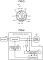
- FIG. 3 is a side view of the first example of the electric blower 100 according to the first embodiment.
- the electric blower 100 includes the blower motor unit 240 and the substrate 210 inside the tubular housing 200.
- the blower motor unit 240 includes blades 230 and the single-phase motor 220.
- the blades 230 are attached to a rotor 221 of the single-phase motor 220.
- the substrate 210 is mounted with the motor controller that controls driving of the single-phase motor 220.
- the motor controller includes an inverter that outputs alternating-current power to the single-phase motor 220.
- the substrate 210 namely, the motor controller 10 is connected to the single-phase motor 220 by lead wires 211 and 212.
- the substrate 210 is disposed in the tubular housing 200 by means of supports 213.
- the single-phase motor 220 is disposed in the tubular housing 200 by means of supports 214.
- the supports 213 and 214 may be formed integrally with or separately from the tubular housing 200.
- the supports 213 and 214 may be rod-shaped or planar. The same applies to other supports below.
- the substrate 210 is not particularly limited in orientation.
- the substrate 210 may be disposed so that its surface, mounted with heat-generating components, comes into contact with the tubular housing 200 via a heat sink that is not illustrated. In other words, the tubular housing 200 may be used as a heat sink.
- FIG. 4 illustrates a circuit configuration of the motor controller 10 mounted on the substrate 210 according to the first embodiment.
- FIG. 5 illustrates a circuit configuration of the inverter 11 included in the motor controller 10 according to the first embodiment.
- the motor controller 10 is connected to a battery 202 and the single-phase motor 220.
- the battery 202 supplies direct-current power that drives the electric blower 100 to the substrate 210, namely, to the motor controller 10.
- the motor controller 10 controls operation of the single-phase motor 220 to rotate the rotor 221 and the blades 230.
- the motor controller 10 includes: the inverter 11; a current detector 20; a voltage detector 21; an analog-to-digital converter 30, a processor 31, and a driving signal generator 32.
- the inverter 11 includes switching elements 51 to 54 to convert the direct-current power supplied from the battery 202 into the alternating-current power and outputs the alternating-current power to the single-phase motor 220 for driving the single-phase motor 220.
- the current detector 20 detects a current flowing in the single-phase motor 220.
- the voltage detector 21 detects a voltage of the alternating-current power applied to the single-phase motor 220.
- the analog-to-digital converter 30 converts an analog signal indicating the current value detected by the current detector 20 and an analog signal indicating the voltage value detected by the voltage detector 21 into digital signals.
- the processor 31 uses the digital signals respectively indicating the current and voltage values obtained from the analog-to-digital converter 30, the processor 31 performs operations including estimation of position of the rotor 221 in the single-phase motor 220 and generates pulse width modulation (PWM) signals for controlling the operation of the single-phase motor 220.
- PWM pulse width modulation
- Any general control method is usable as a control method by the processor 31. Examples of the control method that are usable by the processor 31 include position sensorless vector control, current control, and power control, among others. By being controlled in this way, the single-phase motor 220 of the electric blower 100 can operate at a rotational speed of about 100,000 rpm.
- the driving signal generator 32 On the basis of the PWM signals generated by the processor 31, the driving signal generator 32 generates driving signals that turn on and off the switching elements 51 to 54 of the inverter 11 and outputs the driving signals to the inverter 11.
- the electric blower 100 causes the blades 230 to rotate to draw in air from an inlet port and flow the air toward an exhaust port of the tubular housing 200.
- a wind direction, namely, the air flow is indicated by arrows illustrated in FIG. 2 .
- the wind is shown to flow from left to right.
- the electric blower 100 has an air path inside the tubular housing 200.
- a motor controller that uses a position sensor to detect rotor position and to control operation of the single-phase motor
- the position sensor needs to be disposed in the vicinity of the single-phase motor.
- the motor controller 10 does not include a position sensor that detects the position of the rotor 221 in the single-phase motor 220. Therefore, in the tubular housing 200 of the electric blower 100, the substrate 210 mounted with the motor controller 10 may be disposed in parallel with the air path of the tubular housing 200, that is to say, the direction indicated by the arrows in FIG. 2 . Since the substrate 210 mounted with the motor controller 10 is disposed as illustrated in FIG. 2 and does not block the air path, the electric blower 100 can suppress the pressure loss in the air path and can improve suction power. Consequently, suction force of a product that uses the electric blower 100 can be improved.
- disposing the substrate 210 along the air path enables the electric blower 100 to have the reduced pressure loss in the air path and higher efficiency.
- the electric blower 100 is capable of efficiently cooling down the heat-generating components and other components mounted on the substrate 210.
- the substrate 210 is disposed, inside the tubular housing 200, where the substrate 210 is cooled down directly by the wind that the blower motor unit 240 generates.
- the substrate 210 disposed inside the tubular housing 200 has its surface oriented in parallel with the direction of the wind that the blower motor unit 240 generates.
- a motor controller is provided with a position sensor and a substrate is disposed to block an air path
- a substrate is disposed to block an air path
- air drawn in by an electric blower has a high moisture content
- a greater amount of moisture strikes directly on the substrate.
- the motor controller 10 By having no position sensor, the motor controller 10 according to the present embodiment enables elimination of position sensor attachment from a manufacturing process and a step of adjustment based on variations due to the position sensor installation, thus enabling significant reductions in manufacturing costs. In addition, the motor controller 10 is not affected by aged deterioration of the position sensor, thus enabling improved product quality.
- FIGS. 2 and 3 does not include the battery 202
- the battery 202 may be disposed inside the tubular housing 200.
- FIG. 6 is a sectional view of a second example of the electric blower 100 according to the first embodiment.
- FIG. 7 is a side view of the second example of the electric blower 100 according to the first embodiment.
- This electric blower 100 also includes the battery 202 that supplies direct-current power to the substrate 210, namely, the motor controller 10.
- the battery 202 is disposed downstream of the substrate 210 in the air path inside the tubular housing 200 and is oriented in parallel with the direction of wind that the blower motor unit 240 generates.
- the substrate 210, namely, the motor controller 10 is connected to the battery 202 by lead wires 215 and 216.
- the battery 202 is disposed in the tubular housing 200 by means of supports 217.
- the supports 217 may be formed integrally with or separately from the tubular housing 200.
- the battery 202 may be disposed to contact the tubular housing 200 via a heat sink that is not illustrated. If the heat sink has, for example, a curved surface that faces the tubular housing 200, the battery 202 can be in a more close-fitting position with respect to the tubular housing 200.
- power of a product equipped with the battery 202 is highly dependent on capacity of the battery 202. Therefore, making the most of the capacity of the battery 202 is necessary in order to obtain maximized power of the product. Since voltage that is output from the battery 202 is more or less determined by the battery capacity, increasing current flow is necessary to increase the power. However, the battery 202 has internal impedance. The battery 202 generates heat (I 2 R) due to the current flow, and the heat of the battery 202 grows as the power of the product is increased. Therefore, a heat dissipating means for the battery 202 is needed for increasing the power of the product.
- the battery 202 Compared with those other heat-generating components of the electrical apparatus, the battery 202 has a relatively large volume as a heat source. Therefore, dissipating the heat of the battery 202 takes more time than times dissipating heat of those other heat-generating components.
- the heat-generating components such as the switching elements 51 to 54 of the inverter 11 of the motor controller 10 mounted on the substrate 210 are named as other heat sources.
- PQFN power quad flat no-lead
- the battery 202 uses six cylindrical lithium ion secondary batteries that are each 18 mm in diameter and 65 mm in length, the volume of the battery 202 is about 100,000 mm 3 .
- the battery 202 occupies the large volume compared with those other heat-generating components, and the time required to dissipate its heat is longer than times required to dissipate heats of other heat-generating components.
- the heat that the battery 202 generates could adversely affect other constituent elements of the electrical apparatus. Accordingly, disposing a heat insulating member is conceivable for preventing heat transmission from the battery 202 to the constituent elements other than the battery 202.
- the heat insulating member include a fibrous heat insulator, a foamed heat insulator, an aerogel, and a vacuum insulated member, among others. Disposing any one of these heat insulating members between the battery 202 and those other constituent elements has disadvantages such as an increase in the manufacturing costs and an increase in mass of the electrical apparatus.
- the battery 202 is disposed downwind, while those constituent elements that are weak to heat, such as the substrate 210 and the blower motor unit 240, are disposed upwind as illustrated in FIGS. 6 and 7 .
- the problem of the heating battery 202 adversely affecting those other constituent elements is suppressible in the electric blower 100, and the battery 202 itself can be cooled down at the same time.
- the electric blower 100 can efficiently cool down the battery 202.
- FIG. 8 is a sectional view of a third example of the electric blower 100 according to the first embodiment.
- a side view of the third example of the electric blower 100 according to the first embodiment is the same as FIG. 7 .
- the battery 202 is connected directly to the substrate 210 by means of, for example, terminals or connectors.
- the electric blower 100 is enabled to have fewer losses because of no lead wires 215 and 216 and thus has higher efficiency.
- the electric blower 100 is also enabled to have reduced interconnection impedance between the battery 202 and the substrate 210, so that voltage ripple, current ripple, and others of the power supply can be reduced, and the battery 202 is enabled to have a longer life.
- the substrate 210 of the electric blower 100 is provided with the heat sink, which is not illustrated, this heat sink is shared with the battery 202. This enables elimination of costs associated with another heat sink.
- FIG. 9 is a sectional view of a fourth example of the electric blower 100 according to the first embodiment.
- FIG. 10 is a side view of the fourth example of the electric blower 100 according to the first embodiment.
- the single-phase motor 220 is connected directly to the substrate 210 by means of, for example, terminals or connectors.
- the electric blower 100 is enabled to have reduced pressure loss in an air path because of no lead wires 211 and 212.
- the blower motor unit 240 of the electric blower 100 As the blower motor unit 240 of the electric blower 100 is driven, suction force is produced, causing dust, dirt, and others to be drawn in from a suction part together with air. The dust and the dirt that have been drawn in accumulate in a dust receptacle. Since the inverter 11 enables high-speed rotation of the single-phase motor 220 of the blower motor unit 240, improved air blowing efficiency is enabled even when the blades 230 of the blower motor unit 240 are small in diameter. As a result, the blower motor unit 240 is capable of obtaining a large air volume. Even when the blower motor unit 240 is relatively small in size, the electric blower 100 is capable of providing high suction performance.
- An upper-limit of carrier frequency for efficient driving of the inverter 11 of the electric blower 100 is, for example, about 30 kHz.
- unstable control could conceivably occur when a rotational frequency of the single-phase motor 220 of the blower motor unit 240 is closer to 30 kHz. This problem is avoidable when poles of the single-phase motor 220 of the electric blower 100 are limited to within four in number.
- the stick-shaped vacuum cleaner is required to be smaller in size and lighter in weight.
- the blades 230 of the blower motor unit 240 are made smaller, a proper amount of work required of the vacuum cleaner to be used is difficult to obtain.
- making the blades 230 of the electric blower 100 as small as possible to make the electrical apparatus, namely, the stick-shaped vacuum cleaner smaller in size and lighter in weight and rotating the blades 230 at a higher speed are conceivable.
- rotating the blades 230 of the electric blower 100 at the higher speed requires generation of greater torque by the single-phase motor 220.
- the torque T that the single-phase motor 220 generates when rotating is determined by product of a torque constant Kt and motor current Ia.
- T Kt ⁇ Ia
- increasing the motor current Ia of the electric blower 100 is a conceivable measure for increasing the torque T.
- Increasing the motor current Ia suppresses the above disadvantages associated with the reconfiguration of the single-phase motor 220 of the electric blower 100, such as the increase in the manufacturing costs, the increase in the mass, and the size increase, while enabling the greater torque.
- a material of high thermal conductivity such as metal, adjacent to those including the single-phase motor 220, the battery 202, and the substrate 210 as in the above-described case enables improved heat dissipation for the heat-generating components including the battery 202.
- the single-phase motor 220 in the blower motor unit 240 includes the rotor 221 that uses permanent magnets. This enables efficient driving of the single-phase motor 220 and an energy saving effect. With the current detector 20 and the voltage detector 21 that are used in the control of the single-phase motor 220, the controller 10 can control the inverter 11 with high accuracy.
- Using a wide-bandgap semiconductor for the switching elements 51 to 54 of the inverter 11 leads to formation of low-loss semiconductor devices, enabling fewer switching losses and fewer conduction losses. The reduced losses enable an energy saving effect and operation for a longer time period.
- the switching elements 51 to 54 of the inverter 11 are not limited to MOSFETs that are made using a silicon-based material but may be MOSFETs that are made using the wide-bandgap semiconductor such as silicon carbide, a gallium nitride material, or diamond. At least one of the switching element 51, the switching element 52, the switching element 53, or the switching element 54 may be made using the wide-bandgap semiconductor.
- the wide-bandgap semiconductor generally has a higher voltage resistance and a higher thermal resistance compared with a silicon semiconductor. Therefore, with the use of the wide-bandgap semiconductor for the switching elements 51 to 54, the switching elements have increased voltage resistance and increased allowable current density, and a semiconductor module incorporating the switching elements is enabled to be smaller in size.
- the high thermal resistance of the wide-bandgap semiconductor also enables a smaller-sized heat sink of simplified heat dissipation structure that dissipates heat that the semiconductor module produces. Since the wide-bandgap semiconductor is low-loss, the reduced switching losses and the reduced conduction losses are enabled. The reduced losses enable the energy saving effect and the operation for the longer time period.
- the electric blower 100 includes, inside the tubular housing 200, the blower motor unit 240 and the substrate 210 mounted with the motor controller 10.
- the substrate 210 is disposed where the substrate 210 is cooled down by the wind that the blower motor unit 240 generates.
- the electric blower 100 can efficiently cool down the heat-generating components and can control driving of the single-phase motor 220 even when reduced in size.
- the single-phase motor 220 used in the electric blower 100 can reduce the lead wires 211 and 212 between the single-phase motor 220 and the substrate 210 from three to two in number.
- the electric blower 100 has the reduced lead wires, enabling reduced lead wire costs and reduced losses associated with the lead wires.
- the substrate 210 has a reduced area.
- the motor winding has parallel connection, the lead wires connecting the single-phase motor 220 and the substrate 210 are even in number.
- the terminals connecting the single-phase motor 220 and the substrate 210 are even in number.
- the tubular housing 200 which has a circular section when viewed in its longitudinal direction, has been described as an example including the blower motor unit 240 and the substrate 210; however, this housing shape is not limiting.
- Another housing that may be used to include the blower motor unit 240 and the substrate 210 has a section having the shape of a polygon such as a hexagon or an octagon when viewed in its longitudinal direction. The same applies to the following embodiments.
- the substrate 210 is disposed inside the tubular housing 200. In a description of the second embodiment, the substrate 210 is disposed outside the tubular housing 200.
- FIG. 11 is a sectional view of a first example of an electric blower 100a according to the second embodiment.
- FIG. 12 is a side view of the first example of the electric blower 100a according to the second embodiment.
- the electric blower 100a includes the blower motor unit 240 inside the tubular housing 200, and the substrate 210 outside the tubular housing 200.
- the substrate 210 namely, the motor controller 10 is connected to the single-phase motor 220 by the lead wires 211 and 212.
- the substrate 210 is disposed to have heat-generating components 218 in contact with the tubular housing 200.
- the heat-generating components 218 are used in the above-mentioned inverter 11 and are, for example, power semiconductor devices of a PQFN package.
- the heat-generating components 218 may be disposed to contact the tubular housing 200 via a heat sink that is not illustrated. If the heat sink has, for example, a curved surface that faces the tubular housing 200, each of the heat-generating components 218 can be in a more close-fitting position with respect to the tubular housing 200.
- the substrate 210 is disposed onto the tubular housing 200 by means of supports 219.
- the supports 219 may be formed integrally with or separately from the tubular housing 200.
- the tubular housing 200 is used as the heat sink for the heat-generating components 218. Since the tubular housing 200 receives internal wind from the blower motor unit 240, the tubular housing 200 is capable of lowering its temperature that has been increased by heat from the heat-generating components 218.
- the electric blower 100a is enabled to have reduced pressure loss in an air path inside the tubular housing 200 and higher efficiency. Since dust, dirt, moisture, and others do not easily accumulate on the substrate 210 of the electric blower 100a, a short circuit between patterns is also preventable. Moreover, the electric blower 100a enables efficient cooling down of the heat-generating components 218.
- the substrate 210 is disposed outside the tubular housing 200 in such a position that the substrate 210 is cooled down indirectly by the wind that the blower motor unit 240 generates.
- the substrate 210 is disposed outside the tubular housing 200 in such a manner that the heat-generating components 218 mounted on the substrate 210 are directly or indirectly contact with the tubular housing 200.
- FIGS. 11 and 12 does not include the battery 202
- the battery 202 may be disposed outside the tubular housing 200.
- FIG. 13 is a sectional view of a second example of the electric blower 100a according to the second embodiment.
- FIG. 14 is a side view of the second example of the electric blower 100a according to the second embodiment.
- This electric blower 100a also includes the battery 202 that supplies direct-current power to the substrate 210, namely, the motor controller 10.
- the battery 202 is disposed in such a manner to directly or indirectly contact with the tubular housing 200 outside the tubular housing 200 and is downstream from the substrate 210 with respect to an air path.
- the substrate 210 namely, the motor controller 10 is connected to the battery 202 by the lead wires 215 and 216.
- the battery 202 is disposed onto the tubular housing 200 by means of supports 222.
- the supports 222 may be formed integrally with or separately from the tubular housing 200.
- the battery 202 may be disposed to contact the tubular housing 200 via a heat sink that is not illustrated. If the heat sink has, for example, a curved surface that faces the tubular housing 200, the battery 202 can be in a more close-fitting position with respect to the tubular housing 200.
- the tubular housing 200 is used as the heat sink for the battery 202. Since the tubular housing 200 receives internal wind from the blower motor unit 240, the tubular housing 200 is capable of lowering its temperature that has been increased by heat from the battery 202.
- the electric blower 100a can efficiently cool down the battery 202. Moreover, the electric blower 100a can reduce the pressure loss in the air path and can achieve a higher efficiency.
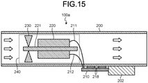
- FIG. 15 is a sectional view of a third example of the electric blower 100a according to the second embodiment.
- a side view of the third example of the electric blower 100a according to the second embodiment is the same as FIG. 14 .
- the battery 202 is connected directly to the substrate 210 by means of, for example, terminals or connectors. This enables elimination of the lead wires 215 and 216 between the battery 202 and the substrate 210 in the electric blower 100a, thus eliminating costs associated with the lead wires 215 and 216.
- the electric blower 100a is enabled to have fewer losses because of no lead wires 215 and 216 and thus has higher efficiency.
- the electric blower 100a is also enabled to have reduced interconnection impedance between the battery 202 and the substrate 210, so that voltage ripple, current ripple, and others of the power supply can be reduced, and the battery 202 is enabled to have a longer life.
- the substrate 210 of the electric blower 100a is provided with the heat sink, which is not illustrated, this heat sink is shared with the battery 202. This enables elimination of costs associated with another heat sink.
- the electric blower 100a includes: the blower motor unit 240 inside the tubular housing 200; and the substrate 210 mounted with the motor controller 10 outside the tubular housing 200.
- the substrate 210 is disposed in a position where the substrate 210 is cooled down by the wind that the blower motor unit 240 generates.
- the electric blower 100a can efficiently cool down the heat-generating components and can control the driving of the single-phase motor 220 even when reduced in size.
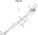
- FIG. 16 illustrates a configuration example of a vacuum cleaner 61 according to the third embodiment that includes the electric blower 100.
- the vacuum cleaner 61 includes: the electric blower 100; a dust receptacle 65; a suction body 63; an extension pipe 62; and an operating part 66.
- a user uses the vacuum cleaner 61 while holding the operating part 66.
- power is supplied from the battery 202 to the blower motor unit 240 via the motor controller 10 of the substrate 210.
- the blower motor unit 240 of the vacuum cleaner 61 is driven, and accordingly, dust is sucked up from the suction body 63 into the dust receptacle 65 through the extension pipe 62.
- the vacuum cleaner 61 is increasingly smaller in size and lighter in weight, and its power density, which refers to power per unit volume, has become higher.
- the configuration of the electric blower 100 is more suitable for this product configuration and enables more efficient cooling down of the heat-generating parts, thus enabling the product to be more compact.
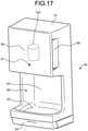
- FIG. 17 illustrates a configuration example of a hand dryer 90 according to the third embodiment that includes the electric blower 100.
- the hand dryer 90 includes: a casing 91; a hand detection sensor 92; a water receptacle 93; a drain receptacle 94; a cover 96; a sensor 97; an air-intake 98; and the electric blower 100.
- the sensor 97 here is either a gyro sensor or a human presence sensor.
- the hand dryer 90 is increasingly required to be thinner.
- the product is also required to be more compact and easier to install with a view to general household penetration. Efficient cooling down of the heat-generating parts is therefore important in order to further the size reduction.
- the configuration of the electric blower 100 is more suitable for this product configuration and enables more efficient cooling down of the heat-generating parts, thus enabling the product to be more compact.
- the electric blower 100 is applicable to any other electrical apparatus carrying a motor.
- the electrical apparatus carrying the motor include a canister vacuum cleaner, an incinerator, a grinder, a dryer, a dust collector, a printing machine, a cleaning machine, confectionery equipment, a tea manufacturing machine, a woodworking machine, a plastic extruder, a cardboard machine, a packaging machine, a hot air generator, OA equipment, and a motor fan.
- the motor fan is an air blowing means as used in object transportation, dust suction, or general ventilation.
Landscapes
- Engineering & Computer Science (AREA)
- Mechanical Engineering (AREA)
- General Engineering & Computer Science (AREA)
- Health & Medical Sciences (AREA)
- Public Health (AREA)
- Physics & Mathematics (AREA)
- Thermal Sciences (AREA)
- Structures Of Non-Positive Displacement Pumps (AREA)
- Electric Suction Cleaners (AREA)
Abstract
Description
- The present invention relates to an electric blower that includes a single-phase motor and also relates to a vacuum cleaner and a hand dryer.
- Conventionally, vacuum cleaners and hand dryers are known among examples of an electrical apparatus equipped with an electric blower. Such electrical apparatuses are reduced in size in order to improve portability, operability during use, and others. For example, in order to achieve a smaller electrical apparatus that serves as a vacuum cleaner and efficiently cool a controller that controls an electric blower, a technique disclosed in Patent Literature 1 is such that substrates for the controller are disposed in an airflow path inside the electric blower.
- Patent Literature 1:
Japanese Patent Application Laid-open No. 2002-21794 - Although the configuration described in Patent Literature 1 shows to efficiently cool down heat-generating components of the circuitry, there is no mention of cooling down other components that constitute the product, and no other cooling effects are provided.
- Electric blowers installed in stick-shaped vacuum cleaners and others are becoming increasingly smaller in size and lighter in weight in order to improve user-friendliness. In order to achieve the downsizing, a single-phase inverter with fewer switching elements is suitable as an inverter that drives the electric blower. Combined with the single-phase inverter, a single-phase permanent-magnet motor is suitable for the electric blower. Meanwhile, the downsized electric blower has a smaller blade diameter and thus has reduced power. Accordingly, a control method that causes high-speed rotation of blades is generally adopted to offset a decrease in blade diameter. This control method uses a position sensor to determine rotor magnetic pole position, and the control is performed based on the rotor magnetic pole position.
- Since the position sensor detects the magnetic pole position by picking up magnetic flux of a rotor magnet in this case, the rotor magnet must be in close proximity to the position sensor, meaning that a substrate provided with the position sensor needs to be attached to the motor. As the substrate becomes integral with the motor, an air path of the electric blower is blocked, problematically causing the product to have increased pressure loss that translates into decreased aerodynamic power. In addition, this electric blower problematically has deteriorated cooling performance for a component that comes after the substrate in the air path.
- The present invention has been made in view of the above, and an object of the present invention is to obtain an electric blower that can efficiently cool down heat-generating components and can control driving of a single-phase motor even when the electric blower is downsized.
- To solve the above problems and achieve the object an electric blower according to the present invention includes: a blower motor unit including a blade and a single-phase motor, the blade being attached to a rotor of the single-phase motor; a substrate mounted with a motor controller that controls driving of the single-phase motor, the motor controller including an inverter that outputs alternating-current power to the single-phase motor; and a housing where the blower motor unit and the substrate are disposed. The substrate is disposed in a position where the substrate is cooled down directly or indirectly by a wind that the blower motor unit generates.
- Even when downsized, the electric blower according to the present invention can achieve efficient cooling down of heat-generating components and can control driving of the single-phase motor.
-
-
FIG. 1 is an external view of an electric blower according to a first embodiment. -
FIG. 2 is a sectional view of a first example of the electric blower according to the first embodiment. -
FIG. 3 is a side view of the first example of the electric blower according to the first embodiment. -
FIG. 4 illustrates a circuit configuration of a motor controller mounted on a substrate according to the first embodiment. -
FIG. 5 illustrates a circuit configuration of an inverter included in the motor controller according to the first embodiment. -
FIG. 6 is a sectional view of a second example of the electric blower according to the first embodiment. -
FIG. 7 is a side view of the second example of the electric blower according to the first embodiment. -
FIG. 8 is a sectional view of a third example of the electric blower according to the first embodiment. -
FIG. 9 is a sectional view of a fourth example of the electric blower according to the first embodiment. -
FIG. 10 is a side view of the fourth example of the electric blower according to the first embodiment. -
FIG. 11 is a sectional view of a first example of an electric blower according to a second embodiment. -
FIG. 12 is a side view of the first example of the electric blower according to the second embodiment. -
FIG. 13 is a sectional view of a second example of the electric blower according to the second embodiment. -
FIG. 14 is a side view of the second example of the electric blower according to the second embodiment. -
FIG. 15 is a sectional view of a third example of the electric blower according to the second embodiment. -
FIG. 16 illustrates a configuration example of a vacuum cleaner according to a third embodiment that includes the electric blower. -
FIG. 17 illustrates a configuration example of a hand dryer according to the third embodiment that includes the electric blower. - With reference to the drawings, a detailed description is hereinafter provided of an electric blower, a vacuum cleaner, and a hand dryer according to embodiments of the present invention. It is to be noted that these embodiments are not restrictive of the present invention.
-
FIG. 1 is an external view of anelectric blower 100 according to the first embodiment of the present invention. The view illustrated byFIG. 1 is defined as a top view of theelectric blower 100 for convenience sake. In actual use, theelectric blower 100 is not limited in orientation. For example, theelectric blower 100 can be used with its bottom side (not illustrated) up. Theelectric blower 100 includes atubular housing 200. Theelectric blower 100 also includes, inside thetubular housing 200, a blower motor unit (not illustrated) and a substrate (not illustrated) mounted with a motor controller that controls driving of a single-phase motor of the blower motor unit. A concrete description is hereinafter provided of each internal structure of theelectric blower 100 with reference to a sectional view of theelectric blower 100 as taken along line A-A ofFIG. 1 and a right side view of theelectric blower 100 with its side illustrated inFIG. 1 being top. -
FIG. 2 is a sectional view of a first example of theelectric blower 100 according to the first embodiment.FIG. 3 is a side view of the first example of theelectric blower 100 according to the first embodiment. As described above, theelectric blower 100 includes theblower motor unit 240 and thesubstrate 210 inside thetubular housing 200. Theblower motor unit 240 includesblades 230 and the single-phase motor 220. Theblades 230 are attached to arotor 221 of the single-phase motor 220. Thesubstrate 210 is mounted with the motor controller that controls driving of the single-phase motor 220. The motor controller includes an inverter that outputs alternating-current power to the single-phase motor 220. Thesubstrate 210, namely, the motor controller 10 is connected to the single-phase motor 220 bylead wires substrate 210 is disposed in thetubular housing 200 by means ofsupports 213. The single-phase motor 220 is disposed in thetubular housing 200 by means ofsupports 214. Thesupports tubular housing 200. Thesupports substrate 210 is not particularly limited in orientation. Thesubstrate 210 may be disposed so that its surface, mounted with heat-generating components, comes into contact with thetubular housing 200 via a heat sink that is not illustrated. In other words, thetubular housing 200 may be used as a heat sink. -
FIG. 4 illustrates a circuit configuration of the motor controller 10 mounted on thesubstrate 210 according to the first embodiment.FIG. 5 illustrates a circuit configuration of the inverter 11 included in the motor controller 10 according to the first embodiment. As illustrated inFIG. 4 , the motor controller 10 is connected to abattery 202 and the single-phase motor 220. Thebattery 202 supplies direct-current power that drives theelectric blower 100 to thesubstrate 210, namely, to the motor controller 10. The motor controller 10 controls operation of the single-phase motor 220 to rotate therotor 221 and theblades 230. The motor controller 10 includes: the inverter 11; acurrent detector 20; avoltage detector 21; an analog-to-digital converter 30, a processor 31, and adriving signal generator 32. - The inverter 11 includes switching
elements 51 to 54 to convert the direct-current power supplied from thebattery 202 into the alternating-current power and outputs the alternating-current power to the single-phase motor 220 for driving the single-phase motor 220. Thecurrent detector 20 detects a current flowing in the single-phase motor 220. Thevoltage detector 21 detects a voltage of the alternating-current power applied to the single-phase motor 220. The analog-to-digital converter 30 converts an analog signal indicating the current value detected by thecurrent detector 20 and an analog signal indicating the voltage value detected by thevoltage detector 21 into digital signals. - Using the digital signals respectively indicating the current and voltage values obtained from the analog-to-
digital converter 30, the processor 31 performs operations including estimation of position of therotor 221 in the single-phase motor 220 and generates pulse width modulation (PWM) signals for controlling the operation of the single-phase motor 220. Any general control method is usable as a control method by the processor 31. Examples of the control method that are usable by the processor 31 include position sensorless vector control, current control, and power control, among others. By being controlled in this way, the single-phase motor 220 of theelectric blower 100 can operate at a rotational speed of about 100,000 rpm. On the basis of the PWM signals generated by the processor 31, the drivingsignal generator 32 generates driving signals that turn on and off the switchingelements 51 to 54 of the inverter 11 and outputs the driving signals to the inverter 11. - Under the control of the motor controller 10, the
electric blower 100 causes theblades 230 to rotate to draw in air from an inlet port and flow the air toward an exhaust port of thetubular housing 200. A wind direction, namely, the air flow is indicated by arrows illustrated inFIG. 2 . InFIG. 2 , the wind is shown to flow from left to right. The same applies to other drawings that follow. As illustrated, theelectric blower 100 has an air path inside thetubular housing 200. - In general, a motor controller that uses a position sensor to detect rotor position and to control operation of the single-phase motor, the position sensor needs to be disposed in the vicinity of the single-phase motor. To explain using the example of
FIG. 2 , this means that thesubstrate 210 needs to be disposed downwind of the single-phase motor 220 near therotor 221. In this case, thesubstrate 210 blocks the air path inside thetubular housing 200. - By contrast, the motor controller 10 according to the present embodiment does not include a position sensor that detects the position of the
rotor 221 in the single-phase motor 220. Therefore, in thetubular housing 200 of theelectric blower 100, thesubstrate 210 mounted with the motor controller 10 may be disposed in parallel with the air path of thetubular housing 200, that is to say, the direction indicated by the arrows inFIG. 2 . Since thesubstrate 210 mounted with the motor controller 10 is disposed as illustrated inFIG. 2 and does not block the air path, theelectric blower 100 can suppress the pressure loss in the air path and can improve suction power. Consequently, suction force of a product that uses theelectric blower 100 can be improved. In other words, disposing thesubstrate 210 along the air path enables theelectric blower 100 to have the reduced pressure loss in the air path and higher efficiency. Moreover, theelectric blower 100 is capable of efficiently cooling down the heat-generating components and other components mounted on thesubstrate 210. - Thus the
substrate 210 is disposed, inside thetubular housing 200, where thesubstrate 210 is cooled down directly by the wind that theblower motor unit 240 generates. Thesubstrate 210 disposed inside thetubular housing 200 has its surface oriented in parallel with the direction of the wind that theblower motor unit 240 generates. - If a motor controller is provided with a position sensor and a substrate is disposed to block an air path, when air drawn in by an electric blower has a high moisture content, a greater amount of moisture strikes directly on the substrate. This raises a concern about ion migration that during voltage application to the substrate, ionized metals migrate between electrodes and result in a short circuit. There is also a concern about short-circuiting due to accumulation of dust, dirt, and others. Therefore, a method such as applying a moisture-proofing agent to the substrate or isolating the substrate from the air path is taken as a measure when the position sensor is provided; however, either of the methods brings about an increase in manufacturing costs.
- By contrast, a smaller amount of moisture strikes directly on the
substrate 210 for the motor controller 10 according to the present embodiment, so that ion migration can be suppressed and usage of moisture-proofing agent can be reduced. Since dust, dirt, moisture, and others do not easily accumulate, a short circuit between patterns of the motor controller 10 is also preventable. Moreover, compared to when the position sensor is provided, there is increased flexibility in substrate placement, which enables thesubstrate 210 for the motor controller 10 to be disposed outside thetubular housing 200 as is described later to have improved quality. - By having no position sensor, the motor controller 10 according to the present embodiment enables elimination of position sensor attachment from a manufacturing process and a step of adjustment based on variations due to the position sensor installation, thus enabling significant reductions in manufacturing costs. In addition, the motor controller 10 is not affected by aged deterioration of the position sensor, thus enabling improved product quality.
- Although the
electric blower 100 illustrated inFIGS. 2 and3 does not include thebattery 202, thebattery 202 may be disposed inside thetubular housing 200.FIG. 6 is a sectional view of a second example of theelectric blower 100 according to the first embodiment.FIG. 7 is a side view of the second example of theelectric blower 100 according to the first embodiment. Thiselectric blower 100 also includes thebattery 202 that supplies direct-current power to thesubstrate 210, namely, the motor controller 10. Thebattery 202 is disposed downstream of thesubstrate 210 in the air path inside thetubular housing 200 and is oriented in parallel with the direction of wind that theblower motor unit 240 generates. Thesubstrate 210, namely, the motor controller 10 is connected to thebattery 202 bylead wires battery 202 is disposed in thetubular housing 200 by means ofsupports 217. Thesupports 217 may be formed integrally with or separately from thetubular housing 200. Thebattery 202 may be disposed to contact thetubular housing 200 via a heat sink that is not illustrated. If the heat sink has, for example, a curved surface that faces thetubular housing 200, thebattery 202 can be in a more close-fitting position with respect to thetubular housing 200. - In general, power of a product equipped with the
battery 202, such as suction power of a vacuum cleaner that is described later, is highly dependent on capacity of thebattery 202. Therefore, making the most of the capacity of thebattery 202 is necessary in order to obtain maximized power of the product. Since voltage that is output from thebattery 202 is more or less determined by the battery capacity, increasing current flow is necessary to increase the power. However, thebattery 202 has internal impedance. Thebattery 202 generates heat (I2R) due to the current flow, and the heat of thebattery 202 grows as the power of the product is increased. Therefore, a heat dissipating means for thebattery 202 is needed for increasing the power of the product. - Compared with those other heat-generating components of the electrical apparatus, the
battery 202 has a relatively large volume as a heat source. Therefore, dissipating the heat of thebattery 202 takes more time than times dissipating heat of those other heat-generating components. The heat-generating components such as the switchingelements 51 to 54 of the inverter 11 of the motor controller 10 mounted on thesubstrate 210 are named as other heat sources. When, for example, power semiconductor devices of a 5 mm×6 mm power quad flat no-lead (PQFN) package are used as the switchingelements 51 to 54, each of the switchingelements 51 to 54 occupies a volume of 5 mm×6 mm×1 mm=30 mm3. On the other hand, when thebattery 202 uses six cylindrical lithium ion secondary batteries that are each 18 mm in diameter and 65 mm in length, the volume of thebattery 202 is about 100,000 mm3. Thus thebattery 202 occupies the large volume compared with those other heat-generating components, and the time required to dissipate its heat is longer than times required to dissipate heats of other heat-generating components. - Conceivably, the heat that the
battery 202 generates could adversely affect other constituent elements of the electrical apparatus. Accordingly, disposing a heat insulating member is conceivable for preventing heat transmission from thebattery 202 to the constituent elements other than thebattery 202. Examples of the heat insulating member include a fibrous heat insulator, a foamed heat insulator, an aerogel, and a vacuum insulated member, among others. Disposing any one of these heat insulating members between thebattery 202 and those other constituent elements has disadvantages such as an increase in the manufacturing costs and an increase in mass of the electrical apparatus. - Therefore, inside the
tubular housing 200 of theelectric blower 100, thebattery 202 is disposed downwind, while those constituent elements that are weak to heat, such as thesubstrate 210 and theblower motor unit 240, are disposed upwind as illustrated inFIGS. 6 and7 . In this way, the problem of theheating battery 202 adversely affecting those other constituent elements is suppressible in theelectric blower 100, and thebattery 202 itself can be cooled down at the same time. Theelectric blower 100 can efficiently cool down thebattery 202. - Although the
battery 202 and thesubstrate 210 are connected by thelead wires FIGS. 6 and7 , thebattery 202 may be connected directly to thesubstrate 210.FIG. 8 is a sectional view of a third example of theelectric blower 100 according to the first embodiment. A side view of the third example of theelectric blower 100 according to the first embodiment is the same asFIG. 7 . In the third example of theelectric blower 100 according to the first embodiment, thebattery 202 is connected directly to thesubstrate 210 by means of, for example, terminals or connectors. - This enables elimination of the
lead wires battery 202 and thesubstrate 210 in theelectric blower 100, thus eliminating costs associated with thelead wires electric blower 100 is enabled to have fewer losses because of nolead wires electric blower 100 is also enabled to have reduced interconnection impedance between thebattery 202 and thesubstrate 210, so that voltage ripple, current ripple, and others of the power supply can be reduced, and thebattery 202 is enabled to have a longer life. When thesubstrate 210 of theelectric blower 100 is provided with the heat sink, which is not illustrated, this heat sink is shared with thebattery 202. This enables elimination of costs associated with another heat sink. - Elimination of the
lead wires phase motor 220 and thesubstrate 210 is also possible in theelectric blower 100.FIG. 9 is a sectional view of a fourth example of theelectric blower 100 according to the first embodiment.FIG. 10 is a side view of the fourth example of theelectric blower 100 according to the first embodiment. In the fourth example of theelectric blower 100 according to the first embodiment, the single-phase motor 220 is connected directly to thesubstrate 210 by means of, for example, terminals or connectors. - This enables elimination of the
lead wires phase motor 220 and thesubstrate 210, thus enabling theelectric blower 100 to have fewer losses and higher efficiency. Moreover, theelectric blower 100 is enabled to have reduced pressure loss in an air path because of nolead wires - A description is provided of operation of the
electric blower 100 installed in the vacuum cleaner that is stick-shaped. As theblower motor unit 240 of theelectric blower 100 is driven, suction force is produced, causing dust, dirt, and others to be drawn in from a suction part together with air. The dust and the dirt that have been drawn in accumulate in a dust receptacle. Since the inverter 11 enables high-speed rotation of the single-phase motor 220 of theblower motor unit 240, improved air blowing efficiency is enabled even when theblades 230 of theblower motor unit 240 are small in diameter. As a result, theblower motor unit 240 is capable of obtaining a large air volume. Even when theblower motor unit 240 is relatively small in size, theelectric blower 100 is capable of providing high suction performance. - An upper-limit of carrier frequency for efficient driving of the inverter 11 of the
electric blower 100 is, for example, about 30 kHz. On the other hand, unstable control could conceivably occur when a rotational frequency of the single-phase motor 220 of theblower motor unit 240 is closer to 30 kHz. This problem is avoidable when poles of the single-phase motor 220 of theelectric blower 100 are limited to within four in number. - In order to have improved operability, the stick-shaped vacuum cleaner is required to be smaller in size and lighter in weight. However, when the
blades 230 of theblower motor unit 240 are made smaller, a proper amount of work required of the vacuum cleaner to be used is difficult to obtain. In order to ensure the required amount of work, making theblades 230 of theelectric blower 100 as small as possible to make the electrical apparatus, namely, the stick-shaped vacuum cleaner smaller in size and lighter in weight and rotating theblades 230 at a higher speed are conceivable. However, rotating theblades 230 of theelectric blower 100 at the higher speed requires generation of greater torque by the single-phase motor 220. - As shown by Formula (1) below, the torque T that the single-
phase motor 220 generates when rotating is determined by product of a torque constant Kt and motor current Ia.
- In order to increase the torque T, reconfiguring the single-
phase motor 220 of theelectric blower 100 to obtain a greater torque constant Kt and increasing the motor current Ia are conceivable. In order to increase the torque constant Kt, conceivable measures for the single-phase motor 220 include increasing turns of a motor winding, using stronger magnets, and increasing a thickness of laminations of a stator. However, any of these measures has disadvantages such as an increase in the manufacturing costs, an increase in mass of the single-phase motor 220, and an increase in size of the single-phase motor 220. - Accordingly, increasing the motor current Ia of the
electric blower 100 is a conceivable measure for increasing the torque T. Increasing the motor current Ia suppresses the above disadvantages associated with the reconfiguration of the single-phase motor 220 of theelectric blower 100, such as the increase in the manufacturing costs, the increase in the mass, and the size increase, while enabling the greater torque. - However, when the motor current Ia of the
electric blower 100 is increased, parts where the current flows conceivably generate an increased amount of heat. Therefore, if the motor current Ia of theelectric blower 100 reaches a certain value or more, using a heat-resistant or flame-retardant material adjacent to those including the single-phase motor 220, thebattery 202, and thesubstrate 210 is a conceivable example of a measure for preventing damage to the apparatus due to the heat generation. Theelectric blower 100 configured in this way enables improved reliability of the apparatus. Using a material of high thermal conductivity, such as metal, adjacent to those including the single-phase motor 220, thebattery 202, and thesubstrate 210 as in the above-described case enables improved heat dissipation for the heat-generating components including thebattery 202. - The single-
phase motor 220 in theblower motor unit 240 includes therotor 221 that uses permanent magnets. This enables efficient driving of the single-phase motor 220 and an energy saving effect. With thecurrent detector 20 and thevoltage detector 21 that are used in the control of the single-phase motor 220, the controller 10 can control the inverter 11 with high accuracy. - Using a wide-bandgap semiconductor for the
switching elements 51 to 54 of the inverter 11 leads to formation of low-loss semiconductor devices, enabling fewer switching losses and fewer conduction losses. The reduced losses enable an energy saving effect and operation for a longer time period. - The switching
elements 51 to 54 of the inverter 11 are not limited to MOSFETs that are made using a silicon-based material but may be MOSFETs that are made using the wide-bandgap semiconductor such as silicon carbide, a gallium nitride material, or diamond. At least one of the switchingelement 51, the switchingelement 52, the switchingelement 53, or the switchingelement 54 may be made using the wide-bandgap semiconductor. - The wide-bandgap semiconductor generally has a higher voltage resistance and a higher thermal resistance compared with a silicon semiconductor. Therefore, with the use of the wide-bandgap semiconductor for the
switching elements 51 to 54, the switching elements have increased voltage resistance and increased allowable current density, and a semiconductor module incorporating the switching elements is enabled to be smaller in size. The high thermal resistance of the wide-bandgap semiconductor also enables a smaller-sized heat sink of simplified heat dissipation structure that dissipates heat that the semiconductor module produces. Since the wide-bandgap semiconductor is low-loss, the reduced switching losses and the reduced conduction losses are enabled. The reduced losses enable the energy saving effect and the operation for the longer time period. - As described above, the
electric blower 100 according to the present embodiment includes, inside thetubular housing 200, theblower motor unit 240 and thesubstrate 210 mounted with the motor controller 10. Thesubstrate 210 is disposed where thesubstrate 210 is cooled down by the wind that theblower motor unit 240 generates. Thus theelectric blower 100 can efficiently cool down the heat-generating components and can control driving of the single-phase motor 220 even when reduced in size. - Compared with a three-phase motor, the single-
phase motor 220 used in theelectric blower 100 can reduce thelead wires phase motor 220 and thesubstrate 210 from three to two in number. Compared to when the three-phase motor is used, theelectric blower 100 has the reduced lead wires, enabling reduced lead wire costs and reduced losses associated with the lead wires. With reduced substrate terminal joints, thesubstrate 210 has a reduced area. When the motor winding has parallel connection, the lead wires connecting the single-phase motor 220 and thesubstrate 210 are even in number. When the single-phase motor 220 is connected directly to thesubstrate 210, the terminals connecting the single-phase motor 220 and thesubstrate 210 are even in number. - In the present embodiment, the
tubular housing 200, which has a circular section when viewed in its longitudinal direction, has been described as an example including theblower motor unit 240 and thesubstrate 210; however, this housing shape is not limiting. Another housing that may be used to include theblower motor unit 240 and thesubstrate 210 has a section having the shape of a polygon such as a hexagon or an octagon when viewed in its longitudinal direction. The same applies to the following embodiments. - In the first embodiment, the
substrate 210 is disposed inside thetubular housing 200. In a description of the second embodiment, thesubstrate 210 is disposed outside thetubular housing 200. -
FIG. 11 is a sectional view of a first example of anelectric blower 100a according to the second embodiment.FIG. 12 is a side view of the first example of theelectric blower 100a according to the second embodiment. Theelectric blower 100a includes theblower motor unit 240 inside thetubular housing 200, and thesubstrate 210 outside thetubular housing 200. Thesubstrate 210, namely, the motor controller 10 is connected to the single-phase motor 220 by thelead wires substrate 210 is disposed to have heat-generatingcomponents 218 in contact with thetubular housing 200. The heat-generatingcomponents 218 are used in the above-mentioned inverter 11 and are, for example, power semiconductor devices of a PQFN package. The heat-generatingcomponents 218 may be disposed to contact thetubular housing 200 via a heat sink that is not illustrated. If the heat sink has, for example, a curved surface that faces thetubular housing 200, each of the heat-generatingcomponents 218 can be in a more close-fitting position with respect to thetubular housing 200. Thesubstrate 210 is disposed onto thetubular housing 200 by means ofsupports 219. Thesupports 219 may be formed integrally with or separately from thetubular housing 200. - In the
electric blower 100a, thetubular housing 200 is used as the heat sink for the heat-generatingcomponents 218. Since thetubular housing 200 receives internal wind from theblower motor unit 240, thetubular housing 200 is capable of lowering its temperature that has been increased by heat from the heat-generatingcomponents 218. - Since the
substrate 210 is disposed outside thetubular housing 200, theelectric blower 100a is enabled to have reduced pressure loss in an air path inside thetubular housing 200 and higher efficiency. Since dust, dirt, moisture, and others do not easily accumulate on thesubstrate 210 of theelectric blower 100a, a short circuit between patterns is also preventable. Moreover, theelectric blower 100a enables efficient cooling down of the heat-generatingcomponents 218. Thesubstrate 210 is disposed outside thetubular housing 200 in such a position that thesubstrate 210 is cooled down indirectly by the wind that theblower motor unit 240 generates. Thesubstrate 210 is disposed outside thetubular housing 200 in such a manner that the heat-generatingcomponents 218 mounted on thesubstrate 210 are directly or indirectly contact with thetubular housing 200. - Although the
electric blower 100a illustrated inFIGS. 11 and 12 does not include thebattery 202, thebattery 202 may be disposed outside thetubular housing 200.FIG. 13 is a sectional view of a second example of theelectric blower 100a according to the second embodiment.FIG. 14 is a side view of the second example of theelectric blower 100a according to the second embodiment. Thiselectric blower 100a also includes thebattery 202 that supplies direct-current power to thesubstrate 210, namely, the motor controller 10. Thebattery 202 is disposed in such a manner to directly or indirectly contact with thetubular housing 200 outside thetubular housing 200 and is downstream from thesubstrate 210 with respect to an air path. Thesubstrate 210, namely, the motor controller 10 is connected to thebattery 202 by thelead wires battery 202 is disposed onto thetubular housing 200 by means ofsupports 222. Thesupports 222 may be formed integrally with or separately from thetubular housing 200. Thebattery 202 may be disposed to contact thetubular housing 200 via a heat sink that is not illustrated. If the heat sink has, for example, a curved surface that faces thetubular housing 200, thebattery 202 can be in a more close-fitting position with respect to thetubular housing 200. - In the
electric blower 100a thetubular housing 200 is used as the heat sink for thebattery 202. Since thetubular housing 200 receives internal wind from theblower motor unit 240, thetubular housing 200 is capable of lowering its temperature that has been increased by heat from thebattery 202. - Since the
battery 202 is disposed outside thetubular housing 200, theelectric blower 100a can efficiently cool down thebattery 202. Moreover, theelectric blower 100a can reduce the pressure loss in the air path and can achieve a higher efficiency. - Although the
battery 202 and thesubstrate 210 are connected by thelead wires FIGS. 13 and 14 , thebattery 202 may be connected directly to thesubstrate 210.FIG. 15 is a sectional view of a third example of theelectric blower 100a according to the second embodiment. A side view of the third example of theelectric blower 100a according to the second embodiment is the same asFIG. 14 . In the third example of theelectric blower 100a according to the second embodiment, thebattery 202 is connected directly to thesubstrate 210 by means of, for example, terminals or connectors. This enables elimination of thelead wires battery 202 and thesubstrate 210 in theelectric blower 100a, thus eliminating costs associated with thelead wires electric blower 100a is enabled to have fewer losses because of nolead wires electric blower 100a is also enabled to have reduced interconnection impedance between thebattery 202 and thesubstrate 210, so that voltage ripple, current ripple, and others of the power supply can be reduced, and thebattery 202 is enabled to have a longer life. When thesubstrate 210 of theelectric blower 100a is provided with the heat sink, which is not illustrated, this heat sink is shared with thebattery 202. This enables elimination of costs associated with another heat sink. - As described above, the
electric blower 100a according to the present embodiment includes: theblower motor unit 240 inside thetubular housing 200; and thesubstrate 210 mounted with the motor controller 10 outside thetubular housing 200. Thesubstrate 210 is disposed in a position where thesubstrate 210 is cooled down by the wind that theblower motor unit 240 generates. Thus theelectric blower 100a can efficiently cool down the heat-generating components and can control the driving of the single-phase motor 220 even when reduced in size. - In the third embodiment, a description is provided of examples of application of the
electric blower 100 according to the first embodiment. The examples to describe use theelectric blower 100 according to the first embodiment; however, theelectric blower 100a according to the second embodiment is also applicable. -
FIG. 16 illustrates a configuration example of avacuum cleaner 61 according to the third embodiment that includes theelectric blower 100. Thevacuum cleaner 61 includes: theelectric blower 100; adust receptacle 65; asuction body 63; anextension pipe 62; and an operatingpart 66. A user uses thevacuum cleaner 61 while holding the operatingpart 66. As the user turns on a power switch that is not illustrated, power is supplied from thebattery 202 to theblower motor unit 240 via the motor controller 10 of thesubstrate 210. Theblower motor unit 240 of thevacuum cleaner 61 is driven, and accordingly, dust is sucked up from thesuction body 63 into thedust receptacle 65 through theextension pipe 62. - The
vacuum cleaner 61 is increasingly smaller in size and lighter in weight, and its power density, which refers to power per unit volume, has become higher. The configuration of theelectric blower 100 is more suitable for this product configuration and enables more efficient cooling down of the heat-generating parts, thus enabling the product to be more compact. -
FIG. 17 illustrates a configuration example of ahand dryer 90 according to the third embodiment that includes theelectric blower 100. Thehand dryer 90 includes: acasing 91; ahand detection sensor 92; awater receptacle 93; adrain receptacle 94; acover 96; asensor 97; an air-intake 98; and theelectric blower 100. Thesensor 97 here is either a gyro sensor or a human presence sensor. When a hand is inserted into ahand insertion part 99 above thewater receptacle 93 of thehand dryer 90, water is blown by air sent from theelectric blower 100 and collected in thewater receptacle 93, and is then stored in thedrain receptacle 94. - Due to locational restrictions, the
hand dryer 90 is increasingly required to be thinner. The product is also required to be more compact and easier to install with a view to general household penetration. Efficient cooling down of the heat-generating parts is therefore important in order to further the size reduction. The configuration of theelectric blower 100 is more suitable for this product configuration and enables more efficient cooling down of the heat-generating parts, thus enabling the product to be more compact. - The examples of application of the
electric blower 100 to thevacuum cleaner 61 and thehand dryer 90 have been described above in the present embodiment; however, theelectric blower 100 is applicable to any other electrical apparatus carrying a motor. Examples of the electrical apparatus carrying the motor include a canister vacuum cleaner, an incinerator, a grinder, a dryer, a dust collector, a printing machine, a cleaning machine, confectionery equipment, a tea manufacturing machine, a woodworking machine, a plastic extruder, a cardboard machine, a packaging machine, a hot air generator, OA equipment, and a motor fan. The motor fan is an air blowing means as used in object transportation, dust suction, or general ventilation. - The above configurations illustrated in the embodiments are illustrative of contents of the present invention, can be combined with other techniques that are publicly known, and can be partly omitted or changed without departing from the gist of the present invention.
- 10 motor controller; 11 inverter; 20 current detector; 21 voltage detector; 30 analog-to-digital converter; 31 processor; 32 driving signal generator; 51 to 54 switching element; 61 vacuum cleaner; 62 extension pipe; 63 suction body; 65 dust receptacle; 66 operating part; 90 hand dryer; 91 casing; 92 hand detection sensor; 93 water receptacle; 94 drain receptacle; 96 cover; 97 sensor; 98 air-intake; 99 hand insertion part; 100, 100a electric blower; 200 tubular housing; 202 battery; 210 substrate; 211, 212, 215, 216 lead wire; 213, 214, 217, 219, 222 support; 218 heat-generating component; 220 single-phase motor; 221 rotor; 230 blade; 240 blower motor unit.
Claims (11)
- An electric blower comprising:a blower motor unit including a blade and a single-phase motor, the blade being attached to a rotor of the single-phase motor;a substrate mounted with a motor controller that controls driving of the single-phase motor, the motor controller including an inverter that outputs alternating-current power to the single-phase motor; anda housing where the blower motor unit and the substrate are disposed, whereinthe substrate is disposed in a position where the substrate is cooled down directly or indirectly by a wind that the blower motor unit generates.
- The electric blower according to claim 1, wherein
the substrate is disposed inside the housing and includes a surface oriented in parallel with a direction of the wind that the blower motor unit generates. - The electric blower according to claim 2, further comprising
a battery that supplies direct-current power to the motor controller, the battery being disposed downstream of the substrate in an air path inside the housing and being oriented in parallel with the direction of the wind that the blower motor unit generates. - The electric blower according to claim 2 or 3, wherein
the substrate and the single-phase motor are connected by one of an even number of lead wires and an even number of terminals. - The electric blower according to claim 1, wherein
the substrate is disposed outside the housing in such a manner that heat-generating components mounted on the substrate directly or indirectly contact with the housing. - The electric blower according to claim 5, further comprising
a battery that supplies direct-current power to the motor controller, the battery being disposed in direct or indirect contact with the housing outside the housing and being downstream from the substrate with respect to an air path. - The electric blower according to claim 3 or 6, wherein
the battery and the substrate are connected directly or by a lead wire. - The electric blower according to any one of claims 1 to 7, wherein at least one of a plurality of switching elements of the inverter is made using a wide-bandgap semiconductor.
- The electric blower according to claim 8, wherein the wide-bandgap semiconductor is one of silicon carbide, gallium nitride, and diamond.
- A vacuum cleaner comprising the electric blower according to any one of claims 1 to 9.
- A hand dryer comprising the electric blower according to any one of claims 1 to 9.
Applications Claiming Priority (1)
| Application Number | Priority Date | Filing Date | Title |
|---|---|---|---|
| PCT/JP2019/015856 WO2020208790A1 (en) | 2019-04-11 | 2019-04-11 | Electric blower, electric vacuum cleaner, and hand dryer |
Publications (2)
| Publication Number | Publication Date |
|---|---|
| EP3954903A1 true EP3954903A1 (en) | 2022-02-16 |
| EP3954903A4 EP3954903A4 (en) | 2022-04-13 |
Family
ID=72751031
Family Applications (1)
| Application Number | Title | Priority Date | Filing Date |
|---|---|---|---|
| EP19924345.2A Withdrawn EP3954903A4 (en) | 2019-04-11 | 2019-04-11 | ELECTRIC BLOWER, ELECTRIC VACUUM, AND HAND DRYER |
Country Status (4)
| Country | Link |
|---|---|
| EP (1) | EP3954903A4 (en) |
| JP (1) | JP7086277B2 (en) |
| CN (1) | CN113646542A (en) |
| WO (1) | WO2020208790A1 (en) |
Cited By (2)
| Publication number | Priority date | Publication date | Assignee | Title |
|---|---|---|---|---|
| CN115788927A (en) * | 2022-12-13 | 2023-03-14 | 深圳市极质科技有限公司 | Handheld high-speed fan |
| EP4445481A4 (en) * | 2021-12-10 | 2025-12-24 | Milwaukee Electric Tool Corp | Inverter with large band gap semiconductor components in a power tool |
Families Citing this family (2)
| Publication number | Priority date | Publication date | Assignee | Title |
|---|---|---|---|---|
| CN114876827A (en) | 2021-02-05 | 2022-08-09 | 创科无线普通合伙 | Hair drier |
| WO2023181182A1 (en) * | 2022-03-23 | 2023-09-28 | 三菱電機株式会社 | Motor drive device, electric blower, electric vacuum cleaner, and hand dryer |
Family Cites Families (11)
| Publication number | Priority date | Publication date | Assignee | Title |
|---|---|---|---|---|
| JPH0626494A (en) * | 1992-07-07 | 1994-02-01 | Matsushita Electric Ind Co Ltd | Electric blower |
| US5904471A (en) * | 1996-12-20 | 1999-05-18 | Turbodyne Systems, Inc. | Cooling means for a motor-driven centrifugal air compressor |
| JP4631136B2 (en) | 2000-07-12 | 2011-02-16 | パナソニック株式会社 | Electric blower and electric vacuum cleaner using the same |
| JP2003204902A (en) * | 2002-01-11 | 2003-07-22 | Matsushita Electric Ind Co Ltd | Electric vacuum cleaner |
| CN202507074U (en) * | 2011-12-29 | 2012-10-31 | 上海航天精密机械研究所 | Vacuum clamp for large curved wall board |
| GB2515082B (en) * | 2013-06-13 | 2015-10-28 | Dyson Technology Ltd | Vacuum cleaner |
| JP2016092920A (en) | 2014-10-31 | 2016-05-23 | 三菱電機株式会社 | Electric blower and vacuum cleaner |
| JP2016220474A (en) * | 2015-05-25 | 2016-12-22 | 三菱電機株式会社 | Motor control device, electric blower, vacuum cleaner and hand dryer |
| CN107009640A (en) * | 2017-05-12 | 2017-08-04 | 河北亚大汽车塑料制品有限公司 | A kind of plastics pipe welding fixture |
| CN108582897A (en) * | 2018-06-29 | 2018-09-28 | 信利光电股份有限公司 | A kind of application of a surface fixture and application of a surface machine |
| CN208682604U (en) * | 2018-08-22 | 2019-04-02 | 东风博泽汽车系统有限公司 | It is a kind of for installing the shield solar or lunar halo structure of coolant liquid expansion kettle water pipe |
-
2019
- 2019-04-11 WO PCT/JP2019/015856 patent/WO2020208790A1/en not_active Ceased
- 2019-04-11 JP JP2021513125A patent/JP7086277B2/en not_active Expired - Fee Related
- 2019-04-11 EP EP19924345.2A patent/EP3954903A4/en not_active Withdrawn
- 2019-04-11 CN CN201980094867.9A patent/CN113646542A/en active Pending
Cited By (2)
| Publication number | Priority date | Publication date | Assignee | Title |
|---|---|---|---|---|
| EP4445481A4 (en) * | 2021-12-10 | 2025-12-24 | Milwaukee Electric Tool Corp | Inverter with large band gap semiconductor components in a power tool |
| CN115788927A (en) * | 2022-12-13 | 2023-03-14 | 深圳市极质科技有限公司 | Handheld high-speed fan |
Also Published As
| Publication number | Publication date |
|---|---|
| EP3954903A4 (en) | 2022-04-13 |
| JP7086277B2 (en) | 2022-06-17 |
| WO2020208790A1 (en) | 2020-10-15 |
| CN113646542A (en) | 2021-11-12 |
| JPWO2020208790A1 (en) | 2021-12-02 |
Similar Documents
| Publication | Publication Date | Title |
|---|---|---|
| EP3954903A1 (en) | Electric blower, electric vacuum cleaner, and hand dryer | |
| JP5393014B2 (en) | Converter motor and converter unit | |
| JP4631136B2 (en) | Electric blower and electric vacuum cleaner using the same | |
| US8628309B2 (en) | Turbomolecular pump device and controlling device thereof | |
| EP1479335B1 (en) | Electric blower and electric apparatus equipped therewith | |
| WO2020042611A1 (en) | Axially separated motor for blender | |
| CN104967253B (en) | At a high speed without Hall three-phase motor of dust collector | |
| CN103460567A (en) | Pole shoe | |
| JP4896166B2 (en) | Stick type vacuum cleaner | |
| JP2016092920A (en) | Electric blower and vacuum cleaner | |
| CN101179247A (en) | Motor drive circuit, motor drive method, and semiconductor integrated circuit device | |
| CN206389217U (en) | A Strong Heat Dissipation Type Brushless DC Generator | |
| EP3318167A1 (en) | Cleaner | |
| JP2010004598A (en) | Controller integrated dynamo-electric machine | |
| CN106898592B (en) | Power converter and rotating electrical machine | |
| JP2004068724A (en) | Electric blower and electric cleaner | |
| CN111868388B (en) | Electric blower, electric vacuum cleaner, and hand dryer | |
| US10736476B2 (en) | Electric vacuum cleaner and hand dryer | |
| JP4021436B2 (en) | Electric blower and electric device using this electric blower | |
| CN114762224A (en) | Power electronics section of starter generator without commutator | |
| JP3770239B2 (en) | AC power source direct-coupled brushless DC motor and electrical equipment equipped with the same | |
| JP2010125193A (en) | Stick-type cleaner | |
| JP4021429B2 (en) | Electric blower, electric device using this electric blower, and method for assembling this electric blower | |
| JP2016007108A (en) | Control unit-integrated rotating electrical machine | |
| WO2022040178A1 (en) | Electric motor and method of use |
Legal Events
| Date | Code | Title | Description |
|---|---|---|---|
| STAA | Information on the status of an ep patent application or granted ep patent |
Free format text: STATUS: THE INTERNATIONAL PUBLICATION HAS BEEN MADE |
|
| PUAI | Public reference made under article 153(3) epc to a published international application that has entered the european phase |
Free format text: ORIGINAL CODE: 0009012 |
|
| STAA | Information on the status of an ep patent application or granted ep patent |
Free format text: STATUS: REQUEST FOR EXAMINATION WAS MADE |
|
| 17P | Request for examination filed |
Effective date: 20211001 |
|
| AK | Designated contracting states |
Kind code of ref document: A1 Designated state(s): AL AT BE BG CH CY CZ DE DK EE ES FI FR GB GR HR HU IE IS IT LI LT LU LV MC MK MT NL NO PL PT RO RS SE SI SK SM TR |
|
| A4 | Supplementary search report drawn up and despatched |
Effective date: 20220314 |
|
| RIC1 | Information provided on ipc code assigned before grant |
Ipc: F04D 25/06 20060101ALI20220308BHEP Ipc: F04D 29/00 20060101ALI20220308BHEP Ipc: A47L 9/28 20060101ALI20220308BHEP Ipc: A47L 9/00 20060101ALI20220308BHEP Ipc: A47L 5/24 20060101ALI20220308BHEP Ipc: F04D 29/58 20060101AFI20220308BHEP |
|
| DAV | Request for validation of the european patent (deleted) | ||
| DAX | Request for extension of the european patent (deleted) | ||
| STAA | Information on the status of an ep patent application or granted ep patent |
Free format text: STATUS: EXAMINATION IS IN PROGRESS |
|
| 17Q | First examination report despatched |
Effective date: 20231017 |
|
| GRAP | Despatch of communication of intention to grant a patent |
Free format text: ORIGINAL CODE: EPIDOSNIGR1 |
|
| STAA | Information on the status of an ep patent application or granted ep patent |
Free format text: STATUS: GRANT OF PATENT IS INTENDED |
|
| INTG | Intention to grant announced |
Effective date: 20250327 |
|
| STAA | Information on the status of an ep patent application or granted ep patent |
Free format text: STATUS: THE APPLICATION IS DEEMED TO BE WITHDRAWN |
|
| 18D | Application deemed to be withdrawn |
Effective date: 20250729 |