EP3954498B1 - High accuracy sliding assembly for a manufacturing machine, and manufacturing machine comprising at least one such assembly - Google Patents
High accuracy sliding assembly for a manufacturing machine, and manufacturing machine comprising at least one such assembly Download PDFInfo
- Publication number
- EP3954498B1 EP3954498B1 EP21190621.9A EP21190621A EP3954498B1 EP 3954498 B1 EP3954498 B1 EP 3954498B1 EP 21190621 A EP21190621 A EP 21190621A EP 3954498 B1 EP3954498 B1 EP 3954498B1
- Authority
- EP
- European Patent Office
- Prior art keywords
- sliding member
- sliding
- respect
- active surface
- sliding assembly
- Prior art date
- Legal status (The legal status is an assumption and is not a legal conclusion. Google has not performed a legal analysis and makes no representation as to the accuracy of the status listed.)
- Active
Links
Images




Classifications
-
- B—PERFORMING OPERATIONS; TRANSPORTING
- B23—MACHINE TOOLS; METAL-WORKING NOT OTHERWISE PROVIDED FOR
- B23Q—DETAILS, COMPONENTS, OR ACCESSORIES FOR MACHINE TOOLS, e.g. ARRANGEMENTS FOR COPYING OR CONTROLLING; MACHINE TOOLS IN GENERAL CHARACTERISED BY THE CONSTRUCTION OF PARTICULAR DETAILS OR COMPONENTS; COMBINATIONS OR ASSOCIATIONS OF METAL-WORKING MACHINES, NOT DIRECTED TO A PARTICULAR RESULT
- B23Q1/00—Members which are comprised in the general build-up of a form of machine, particularly relatively large fixed members
- B23Q1/25—Movable or adjustable work or tool supports
- B23Q1/26—Movable or adjustable work or tool supports characterised by constructional features relating to the co-operation of relatively movable members; Means for preventing relative movement of such members
- B23Q1/38—Movable or adjustable work or tool supports characterised by constructional features relating to the co-operation of relatively movable members; Means for preventing relative movement of such members using fluid bearings or fluid cushion supports
- B23Q1/385—Movable or adjustable work or tool supports characterised by constructional features relating to the co-operation of relatively movable members; Means for preventing relative movement of such members using fluid bearings or fluid cushion supports in which the thickness of the fluid-layer is adjustable
-
- B—PERFORMING OPERATIONS; TRANSPORTING
- B23—MACHINE TOOLS; METAL-WORKING NOT OTHERWISE PROVIDED FOR
- B23Q—DETAILS, COMPONENTS, OR ACCESSORIES FOR MACHINE TOOLS, e.g. ARRANGEMENTS FOR COPYING OR CONTROLLING; MACHINE TOOLS IN GENERAL CHARACTERISED BY THE CONSTRUCTION OF PARTICULAR DETAILS OR COMPONENTS; COMBINATIONS OR ASSOCIATIONS OF METAL-WORKING MACHINES, NOT DIRECTED TO A PARTICULAR RESULT
- B23Q1/00—Members which are comprised in the general build-up of a form of machine, particularly relatively large fixed members
- B23Q1/01—Frames, beds, pillars or like members; Arrangement of ways
- B23Q1/017—Arrangements of ways
-
- B—PERFORMING OPERATIONS; TRANSPORTING
- B23—MACHINE TOOLS; METAL-WORKING NOT OTHERWISE PROVIDED FOR
- B23Q—DETAILS, COMPONENTS, OR ACCESSORIES FOR MACHINE TOOLS, e.g. ARRANGEMENTS FOR COPYING OR CONTROLLING; MACHINE TOOLS IN GENERAL CHARACTERISED BY THE CONSTRUCTION OF PARTICULAR DETAILS OR COMPONENTS; COMBINATIONS OR ASSOCIATIONS OF METAL-WORKING MACHINES, NOT DIRECTED TO A PARTICULAR RESULT
- B23Q39/00—Metal-working machines incorporating a plurality of sub-assemblies, each capable of performing a metal-working operation
- B23Q39/02—Metal-working machines incorporating a plurality of sub-assemblies, each capable of performing a metal-working operation the sub-assemblies being capable of being brought to act at a single operating station
- B23Q39/021—Metal-working machines incorporating a plurality of sub-assemblies, each capable of performing a metal-working operation the sub-assemblies being capable of being brought to act at a single operating station with a plurality of toolheads per workholder, whereby the toolhead is a main spindle, a multispindle, a revolver or the like
- B23Q39/022—Metal-working machines incorporating a plurality of sub-assemblies, each capable of performing a metal-working operation the sub-assemblies being capable of being brought to act at a single operating station with a plurality of toolheads per workholder, whereby the toolhead is a main spindle, a multispindle, a revolver or the like with same working direction of toolheads on same workholder
- B23Q39/024—Metal-working machines incorporating a plurality of sub-assemblies, each capable of performing a metal-working operation the sub-assemblies being capable of being brought to act at a single operating station with a plurality of toolheads per workholder, whereby the toolhead is a main spindle, a multispindle, a revolver or the like with same working direction of toolheads on same workholder consecutive working of toolheads
-
- F—MECHANICAL ENGINEERING; LIGHTING; HEATING; WEAPONS; BLASTING
- F16—ENGINEERING ELEMENTS AND UNITS; GENERAL MEASURES FOR PRODUCING AND MAINTAINING EFFECTIVE FUNCTIONING OF MACHINES OR INSTALLATIONS; THERMAL INSULATION IN GENERAL
- F16C—SHAFTS; FLEXIBLE SHAFTS; ELEMENTS OR CRANKSHAFT MECHANISMS; ROTARY BODIES OTHER THAN GEARING ELEMENTS; BEARINGS
- F16C29/00—Bearings for parts moving only linearly
- F16C29/008—Systems with a plurality of bearings, e.g. four carriages supporting a slide on two parallel rails
-
- F—MECHANICAL ENGINEERING; LIGHTING; HEATING; WEAPONS; BLASTING
- F16—ENGINEERING ELEMENTS AND UNITS; GENERAL MEASURES FOR PRODUCING AND MAINTAINING EFFECTIVE FUNCTIONING OF MACHINES OR INSTALLATIONS; THERMAL INSULATION IN GENERAL
- F16C—SHAFTS; FLEXIBLE SHAFTS; ELEMENTS OR CRANKSHAFT MECHANISMS; ROTARY BODIES OTHER THAN GEARING ELEMENTS; BEARINGS
- F16C29/00—Bearings for parts moving only linearly
- F16C29/02—Sliding-contact bearings
- F16C29/025—Hydrostatic or aerostatic
-
- F—MECHANICAL ENGINEERING; LIGHTING; HEATING; WEAPONS; BLASTING
- F16—ENGINEERING ELEMENTS AND UNITS; GENERAL MEASURES FOR PRODUCING AND MAINTAINING EFFECTIVE FUNCTIONING OF MACHINES OR INSTALLATIONS; THERMAL INSULATION IN GENERAL
- F16C—SHAFTS; FLEXIBLE SHAFTS; ELEMENTS OR CRANKSHAFT MECHANISMS; ROTARY BODIES OTHER THAN GEARING ELEMENTS; BEARINGS
- F16C32/00—Bearings not otherwise provided for
- F16C32/06—Bearings not otherwise provided for with moving member supported by a fluid cushion formed, at least to a large extent, otherwise than by movement of the shaft, e.g. hydrostatic air-cushion bearings
-
- F—MECHANICAL ENGINEERING; LIGHTING; HEATING; WEAPONS; BLASTING
- F16—ENGINEERING ELEMENTS AND UNITS; GENERAL MEASURES FOR PRODUCING AND MAINTAINING EFFECTIVE FUNCTIONING OF MACHINES OR INSTALLATIONS; THERMAL INSULATION IN GENERAL
- F16C—SHAFTS; FLEXIBLE SHAFTS; ELEMENTS OR CRANKSHAFT MECHANISMS; ROTARY BODIES OTHER THAN GEARING ELEMENTS; BEARINGS
- F16C32/00—Bearings not otherwise provided for
- F16C32/06—Bearings not otherwise provided for with moving member supported by a fluid cushion formed, at least to a large extent, otherwise than by movement of the shaft, e.g. hydrostatic air-cushion bearings
- F16C32/0603—Bearings not otherwise provided for with moving member supported by a fluid cushion formed, at least to a large extent, otherwise than by movement of the shaft, e.g. hydrostatic air-cushion bearings supported by a gas cushion, e.g. an air cushion
-
- F—MECHANICAL ENGINEERING; LIGHTING; HEATING; WEAPONS; BLASTING
- F16—ENGINEERING ELEMENTS AND UNITS; GENERAL MEASURES FOR PRODUCING AND MAINTAINING EFFECTIVE FUNCTIONING OF MACHINES OR INSTALLATIONS; THERMAL INSULATION IN GENERAL
- F16C—SHAFTS; FLEXIBLE SHAFTS; ELEMENTS OR CRANKSHAFT MECHANISMS; ROTARY BODIES OTHER THAN GEARING ELEMENTS; BEARINGS
- F16C32/00—Bearings not otherwise provided for
- F16C32/06—Bearings not otherwise provided for with moving member supported by a fluid cushion formed, at least to a large extent, otherwise than by movement of the shaft, e.g. hydrostatic air-cushion bearings
- F16C32/0603—Bearings not otherwise provided for with moving member supported by a fluid cushion formed, at least to a large extent, otherwise than by movement of the shaft, e.g. hydrostatic air-cushion bearings supported by a gas cushion, e.g. an air cushion
- F16C32/0607—Bearings not otherwise provided for with moving member supported by a fluid cushion formed, at least to a large extent, otherwise than by movement of the shaft, e.g. hydrostatic air-cushion bearings supported by a gas cushion, e.g. an air cushion the gas being retained in a gap, e.g. squeeze film bearings
-
- F—MECHANICAL ENGINEERING; LIGHTING; HEATING; WEAPONS; BLASTING
- F16—ENGINEERING ELEMENTS AND UNITS; GENERAL MEASURES FOR PRODUCING AND MAINTAINING EFFECTIVE FUNCTIONING OF MACHINES OR INSTALLATIONS; THERMAL INSULATION IN GENERAL
- F16C—SHAFTS; FLEXIBLE SHAFTS; ELEMENTS OR CRANKSHAFT MECHANISMS; ROTARY BODIES OTHER THAN GEARING ELEMENTS; BEARINGS
- F16C32/00—Bearings not otherwise provided for
- F16C32/06—Bearings not otherwise provided for with moving member supported by a fluid cushion formed, at least to a large extent, otherwise than by movement of the shaft, e.g. hydrostatic air-cushion bearings
- F16C32/0603—Bearings not otherwise provided for with moving member supported by a fluid cushion formed, at least to a large extent, otherwise than by movement of the shaft, e.g. hydrostatic air-cushion bearings supported by a gas cushion, e.g. an air cushion
- F16C32/0614—Bearings not otherwise provided for with moving member supported by a fluid cushion formed, at least to a large extent, otherwise than by movement of the shaft, e.g. hydrostatic air-cushion bearings supported by a gas cushion, e.g. an air cushion the gas being supplied under pressure, e.g. aerostatic bearings
-
- G—PHYSICS
- G03—PHOTOGRAPHY; CINEMATOGRAPHY; ANALOGOUS TECHNIQUES USING WAVES OTHER THAN OPTICAL WAVES; ELECTROGRAPHY; HOLOGRAPHY
- G03F—PHOTOMECHANICAL PRODUCTION OF TEXTURED OR PATTERNED SURFACES, e.g. FOR PRINTING, FOR PROCESSING OF SEMICONDUCTOR DEVICES; MATERIALS THEREFOR; ORIGINALS THEREFOR; APPARATUS SPECIALLY ADAPTED THEREFOR
- G03F7/00—Photomechanical, e.g. photolithographic, production of textured or patterned surfaces, e.g. printing surfaces; Materials therefor, e.g. comprising photoresists; Apparatus specially adapted therefor
- G03F7/70—Microphotolithographic exposure; Apparatus therefor
- G03F7/70691—Handling of masks or workpieces
- G03F7/70716—Stages
-
- G—PHYSICS
- G03—PHOTOGRAPHY; CINEMATOGRAPHY; ANALOGOUS TECHNIQUES USING WAVES OTHER THAN OPTICAL WAVES; ELECTROGRAPHY; HOLOGRAPHY
- G03F—PHOTOMECHANICAL PRODUCTION OF TEXTURED OR PATTERNED SURFACES, e.g. FOR PRINTING, FOR PROCESSING OF SEMICONDUCTOR DEVICES; MATERIALS THEREFOR; ORIGINALS THEREFOR; APPARATUS SPECIALLY ADAPTED THEREFOR
- G03F7/00—Photomechanical, e.g. photolithographic, production of textured or patterned surfaces, e.g. printing surfaces; Materials therefor, e.g. comprising photoresists; Apparatus specially adapted therefor
- G03F7/70—Microphotolithographic exposure; Apparatus therefor
- G03F7/70691—Handling of masks or workpieces
- G03F7/70716—Stages
- G03F7/70725—Stages control
-
- G—PHYSICS
- G03—PHOTOGRAPHY; CINEMATOGRAPHY; ANALOGOUS TECHNIQUES USING WAVES OTHER THAN OPTICAL WAVES; ELECTROGRAPHY; HOLOGRAPHY
- G03F—PHOTOMECHANICAL PRODUCTION OF TEXTURED OR PATTERNED SURFACES, e.g. FOR PRINTING, FOR PROCESSING OF SEMICONDUCTOR DEVICES; MATERIALS THEREFOR; ORIGINALS THEREFOR; APPARATUS SPECIALLY ADAPTED THEREFOR
- G03F7/00—Photomechanical, e.g. photolithographic, production of textured or patterned surfaces, e.g. printing surfaces; Materials therefor, e.g. comprising photoresists; Apparatus specially adapted therefor
- G03F7/70—Microphotolithographic exposure; Apparatus therefor
- G03F7/70691—Handling of masks or workpieces
- G03F7/70758—Drive means, e.g. actuators, motors for long- or short-stroke modules or fine or coarse driving
-
- G—PHYSICS
- G03—PHOTOGRAPHY; CINEMATOGRAPHY; ANALOGOUS TECHNIQUES USING WAVES OTHER THAN OPTICAL WAVES; ELECTROGRAPHY; HOLOGRAPHY
- G03F—PHOTOMECHANICAL PRODUCTION OF TEXTURED OR PATTERNED SURFACES, e.g. FOR PRINTING, FOR PROCESSING OF SEMICONDUCTOR DEVICES; MATERIALS THEREFOR; ORIGINALS THEREFOR; APPARATUS SPECIALLY ADAPTED THEREFOR
- G03F7/00—Photomechanical, e.g. photolithographic, production of textured or patterned surfaces, e.g. printing surfaces; Materials therefor, e.g. comprising photoresists; Apparatus specially adapted therefor
- G03F7/70—Microphotolithographic exposure; Apparatus therefor
- G03F7/708—Construction of apparatus, e.g. environment aspects, hygiene aspects or materials
- G03F7/70808—Construction details, e.g. housing, load-lock, seals or windows for passing light in or out of apparatus
- G03F7/70816—Bearings
Definitions
- the present invention relates to a sliding assembly, which is intended to equip a high accuracy manufacturing machine.
- a manufacturing machine is typically a Computer Numerical Control (CNC) machine.
- CNC Computer Numerical Control
- this type of CNC machines encompasses machines for the manufacturing of fine optical elements.
- these elements are intended for several industrial applications, in particular medical uses or spatial purposes.
- These elements are also suitable for ultra-precision technologies which are similar to optics, such as polished free components.
- a sliding assembly of the above type generally comprises first a so-called base or reference table, which defines in particular a so-called reference plane. In normal use, this plane is generally horizontal. Moreover, said assembly also comprises at least one slider, also called sliding member. Said slider is movable with respect to the reference plane of the table. In this respect, each slider is provided with moving and positioning means, in particular based on linear motor and encoder technology.
- the invention more particularly focuses on sliders which can be moved with respect to the table, along one single direction.
- the assembly may comprise two or three distinct sliders, each movable along one respective direction (X, Z and Y).
- a sliding assembly also comprises specific bearings.
- said bearings may use liquid lubricant, such as pressurised oil.
- a thin film of said lubricant is provided between the facing surfaces of both the table and the slider.
- the present invention mainly focuses on so-called pneumatic or air bearings.
- the latter use compressed gas, in particular compressed air, to create a consistent thin film upon which the slider rests and moves. This film acts as a virtually frictionless lubricant that facilitates smooth motion between the table and the slider.
- such air bearings provide a number of advantages. First, they are virtually frictionless, and therefore produce no particulate wear materials as they operate. Moreover, they require relatively little maintenance or regular repair, in particular in view of all bearings.
- a first type of sliding assembly equipped with air bearings uses fixed parallel rods, along which moves a sliding member. Air bearings are provided at the interface between the rods and the sliding member. Due to space needed between rods and sliding member, this first solution is not satisfactory since it does not make it possible to reach the required high accuracy of the sliding member.
- the mobile sliding member is wrapped around a fixed guiding member.
- the latter may be dovetail shaped, T shaped, or substantially square shaped.
- Sliding assembly may use linear motors.
- the fixed part of the sliding assembly and the moving sliding member are provided with respectively fixed and mobile linear motor elements.
- This solution also uses encoding means, so as to control the mutual positioning of the different components of the assembly.
- JP 2001 173 654 discloses a hydrostatic bearing, which comprises a massive hyperstatic slider which is parallelepiped like shaped. This slider is adapted to slide immediately above the upper surface of a base table.
- the teaching of this document implies some drawbacks, first linked to mechanical complexity. Indeed, due to its massive shape, the slider cannot cooperate with the peripheral faces of the table. It is therefore necessary to provide some extra fixed supports, protruding with respect to the table, along which the slider may move. Moreover, the arrangements proposed in this document do not make it possible, to reach necessary stability.
- JP 2007 180 283 discloses a lithography system which comprises a mechanism for guiding a movable structure such as the mask blade of a reticle masking device, a movable component connected with the movable structure, and a substantially stationary component for guiding the movable component.
- the movable component includes nozzles for injecting gas into the gap between the movable component and the stationary component.
- the guiding mechanism proposed in this document, has however specific drawbacks. Indeed it is adapted to allow only motions of little stroke, and not higher amplitude motions such as aimed in the present invention.
- one first goal of the invention is to remedy to the drawbacks of the above detailed prior art.
- Another goal of the invention is to provide a high accuracy sliding assembly which uses air bearings, while allowing a displacement accuracy which is similar to that of oil bearings.
- Another goal of the invention is to provide such sliding assembly, which benefits of the same advantages as those of prior air bearings.
- a further goal of the invention is to provide a sliding assembly, which has a very satisfactory stability, during its motion.
- Still another goal of the invention is to provide such a sliding assembly having a relatively simple structure, in particular including a limited number of mechanical components.
- One object of the present invention is a sliding assembly according to appended claim 1.
- Another object of the invention is a manufacturing machine according to appended claim 15.
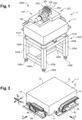
- FIG. 1 illustrates a manufacturing machine, which is referenced 1000 as a whole.
- This machine 1000 is first provided with a frame 1002, substantially composed of vertical posts 1004 and horizontal masts 1006 which rest on travelling rollers 1008.
- Pads 1010 which ensure an anti-vibratory function, are provided at the top of said frame 1002.
- the mechanical elements 1002 to 1010 listed in the present paragraph are known as such and do not form part of the invention, so that they will not be described in further detail.
- This machine 1000 further includes a high accuracy sliding assembly, according to the invention, which is referenced I as a whole.
- Said sliding assembly essentially comprises a so-called base or reference table 1, as well as a first 101 and a second 201 sliding members.
- This base table which is shaped as a parallelepiped, has six surfaces defined with reference to the normal use position:
- Upper surface 10 defines a so-called reference plane P.
- axes X and Z are noted, which are included into said plane P and are parallel respectively to above defined longitudinal surfaces and transversal surfaces.
- Y axis is also noted, which is perpendicular to both X and Z.
- the above-mentioned sliding members 101 and 201 are moved along respectively upper surfaces 10 and peripheral surfaces 12, 14 of the table. These motions shall be carried out with a very high accuracy, according to an objective of the invention.
- at least the above surfaces have an outstanding flatness and quality, due to their chosen material as well as to a polishing treatment to which they are submitted.
- At least the surfaces 10, 12, 14 of the table 1, which cooperate with the sliding members, are made of Absolute Black Granite.
- the whole table will be made of Absolute Black Granite.
- This material, which is known as such, is available from different suppliers. So as to render it substantially non-porous, said Absolute Black Granite is advantageously submitted to an appropriate process, in a way known as such, in order to fill its potential pores.
- the invention also encompasses a base table, which is made of materials that are different from Absolute Black Granite.
- a base table which is made of materials that are different from Absolute Black Granite.
- those skilled in the art may choose materials that have a high stability with respect to both mechanical stresses and temperature variations.
- glass or silicon carbide may be used.
- Absolute Black Granite is the preferred material, in particular due to its relatively low cost.
- At least above-mentioned surfaces 10, 12, 14 of the table 1 are submitted to a so-called optical flatness treatment.
- Said flatness treatment which is known as such, is described for example in the following Internet website: https:/len.wikipedia.org/wiki/Optical flat
- This treatment allows at least a 2 Lambda flatness, advantageously a Lambda/2 flatness, more advantageously a Lambda/4 flatness, where Lambda denotes the wavelength of yellow light, namely 589.3 nanometres.
- said surface 12 is provided with a fixed linear motor element 34, which forms a so-called stator.
- This fixed element 34 extends over a major part of the Z dimension of surface 12.
- element 34 is adapted to cooperate with a mobile linear motor element, which is provided on the sliding member.
- an elongated encoder 36 extends immediately above said fixed element 34. This encoder, which is known as such, makes it possible to control with a very high accuracy the respective positions of the sliding member and the above-mentioned base table.
- the transversal face 14 of the table is equipped with similar mechanical elements, as those 30 to 36 described immediately above.
- the high accuracy sliding assembly of the invention also incorporates at least one sliding member.
- two distinct sliding members 101 and 201 are provided, the one being movable along Z direction whereas the other is movable along the X direction.
- the invention also encompasses sliding assemblies which are equipped with one single sliding member.
- three or more sliding members may be provided.
- Said sliding member is substantially composed of a so-called load support section 120 and a so-called guiding section 160, which are shown in an isolated manner on figure 11 .
- load support section is located in use immediately above upper surface of the table, whereas guiding section is located immediately beside peripheral surface of the table.
- guiding section 160 protrudes downwards from a lateral edge of load support section 120.
- this sliding member 101, as well as the sliding member 201 described hereunder, are substantially L shaped.
- Said load support section 120 is manufactured as a hollow body. With reference to its normal use position, as well as to the motion direction D101 of sliding member 101, the following constitutive parts of this section 120 are noted:
- opposite longitudinal ends 127 and 128 of this section 120 are both opened, namely they are not provided with a solid closing.
- Said guiding section 160 has a structure, which is substantially similar to that of section 120. In an analogous way, the following constitutive parts of this section 160 are noted
- section 160 Opposite longitudinal ends 167 and 168 of section 160 are opened. However, in the present embodiment, section 160 is not provided with ribs since it is not submitted with load.
- the chosen material for both sections 120 and 160 is a so-called high-density ceramic, the density of which is typically over 3.6 kg/dm 3 .
- the invention also encompasses a sliding member 101 or 201, which is made of materials that are different from a ceramic.
- materials that have a high stability with respect to both mechanical stresses and temperature variations, while being light and rigid such as silicon carbide may be used.
- high density ceramic is the preferred material, in particular due to its weight and stiffness.
- Hollow bodies, respectively forming section 120 and 160 are known as such and are commercially available. According to an advantageous embodiment of the invention, these sections are manufactured in a separated manner and are then mutually connected. In particular, these sections are mutually sintered, so as to form the final sliding member 101.
- At least lower surface 121' of lower wall 121 part of section 120, as well as inner surface 163' of wall 163 part of section 160, are submitted to an optical flatness treatment.
- this treatment is substantially analogous to that of table 1, such as above described.
- the dimensions along the longitudinal axis will be adjusted as a function of the load supported by the sliding member.
- the dimensions along the vertical axis will be adjusted to minimise the yaw parameter, in particular as a function of the load and the displacement speed of the sliding member.
- the length of guiding section 160 is superior to that of load support section 120 bearing in mind that, as a variant, the load support section might be longer.
- both lower wall 121 and inner wall 163 are divided into three functional regions.
- lower wall 121 comprises two opposite so-called extremity regions 130 and 135, with reference to the above defined direction D101.
- extremity regions are respectively a front and a rear regions. They are separated by a so-called intermediate region 140.
- regions 130 and 135 are lift regions of the load support section 120, whereas region 140 is a pre-load region of section 120.
- each lift region 130, 135 lower wall 121 is drilled with a single passage respectively referenced 131 and 136. At its upstream end, each passage leads to a respective pipe 132, 137. These different pipes, which are schematically shown on the figures, extend through a common hole 139, which is provided in the upper wall 122. At their respective downstream end, passage 131 of region 130 leads to a first channel 133, whereas passage 136 of other region 135 leads to a second channel 138.
- each channel is elongated, while extending transversely with respect to the motion of the slider.
- This elongated shape is illustrated on figure 20 , wherein the length L133 and the width W133 of channel 133 are referenced.
- the ratio (W133/L133) between this width and this length is between 3% and 10%.
- each channel is fed by one single pipe.
- one given channel may be fed by several pipes, which are provided regularly along the length of this channel. This variant is advantageous, for bringing better regularity in pulse air pressure.
- lower surface 121' of lower wall 121 is provided with recesses, which form cavities 141 and 142.
- the latter are separated by an arche 143, whereas a solid zone 144 is located on the edge of section 120 which is attached to section 160.
- the manufacturing of each cavity is carried out in a way known as such.
- the depth of these cavities is between 1 mm and 5 mm.
- the global area of these cavities namely the sum S141 + S142, represents between 40 and 95%, advantageously between 60 and 90% of the whole area S'120 of active surface 120' part of load support section 120.
- Each cavity leads to a respective passage 145 and 146, drilled in lower wall 121. Said passages lead in turn to pipes are respectively noted 147 and 148, which extend in the above-mentioned hole 139.
- W141 the so-called transverse dimension, with respect to the motion of the slider, of each cavity 141 and 142.
- this dimension is superior to above described length L133 of channel 133, which can also be seen on figure 6 .
- this length is also a transverse dimension, according to the above definition. The technical effect of this feature allows the compressed air to be equally spread around the channels.
- Pipes 132, 137, 147 and 148 extend outside the hollow body, which forms load support section 120, and are received in the cable sleeve 32.
- Pipes 132 and 137 lead into a compressed air source AIR shown in particular on figure 8
- other pipes 147 and 148 lead into a vacuum source VAC shown in particular on figure 9 .
- Both compressed air source and vacuum source which are schematically illustrated on the figures, are known as such. The respective values of compressed air and vacuum will be further described, with reference to the implementation method according to the invention.
- Load support section 120 is also equipped with functional accessories, which are not part of the invention.
- these accessories make it possible to manufacture optical workpieces.
- they comprise a flange 150, which is fixed to upper wall of load support section 120 by any appropriate means, in particular by screwing into section 120.
- This flange supports a spindle 152 which is provided with a clamping jaw 154, which is adapted to maintain a not shown workpiece.
- the mechanical structure of guiding section 160 is substantially similar to that of load support section 120.
- the mechanical elements of section 160 which are analogous to that of section 120, are given the same references added by number 40.
- the two cavities 181 and 182 are located the one behind the other, and not so one beside the other like cavities 141 and 142.
- Four rows of passages 173, 173', as well as 178, 178' are provided the one behind the other.
- the guiding section 160 comprises two end lift regions 180 and 185, like load support section 120.
- the cavities 181 and 182 are provided the one behind the other with respect to the motion direction. Therefore, contrary to load support section, said guiding section 160 comprises two intermediate preload regions 1400 and 1401. Moreover it also comprises two so-called intercalary lift regions 180' and 185', provided in the vicinity of passages 173' and 178'.
- guiding section is equipped with guiding accessories, which are adapted to cooperate with some mechanical elements provided on table 1.
- said section 160 comprises a so-called mobile linear motor member 190, intended to cooperate with the fixed linear motor element 34.
- said guiding section is provided with at least one sensor, which is adapted to cooperate with the elongated encoder 36.
- the present embodiment encompasses two of such sensors, the first one 192 being intended for normal use whereas the other one 193 is intended to a potential emergency use.
- this guiding section is equipped with two limit switches 194 and 195.
- the structure and the operation of above elements 190 to 195 are known as such, so that they will not be described in further details.
- Sliding member 201 has a structure, which is globally similar to that of above described sliding member 101. In particular it comprises two different sections, namely a load support section 220 and a guiding section 260. More in detail the mechanical elements of sliding member 201, which are analogous to that of sliding member 101, are given the same references added by number 100.
- Load support section 220 is provided with functional accessories, which are tools 250 to 254 shown on figure 1 . These tools, which are known as such and thus will not be further described, are intended to the processing of a not shown blank which is received in the spindle 152.
- sliding member 201 is substantially identical to that of sliding member 101.
- this sliding member 201 is provided with active surfaces 221' and 263'. The latter cooperate with the complementary active surfaces 10' and 14' of the table, in the same manner as the cooperation between active surfaces 121' and 163' with the complementary active surfaces 10' and 12'.
- Compressed air is first fed into passages 131 and 136 provided in lower wall 121, as well as into passages 171 and 176 provided in the inner wall 163. As a result, this compressed air leads to lift regions 130 and 135, as well as 180 and 185. Substantially at the same time the vacuum source is actuated, so as to create a vacuum in the cavities 141 and 142, as well as 181 and 182.
- the pressure of this compressed air is between 4 and 6 relative bars.
- the value of the thus created vacuum is between -0.3 bar and -0.5 bar, in particular close to -0.4 relative bar.
- each clearance C and C' are thus created between each active surface and its respective complementary surface.
- the nominal value of each clearance is between 1 micron and 5 microns.
- this clearance value is monitored, in a way known as such. If a measured instantaneous value is outside a predetermined range, the value of at least one of compressed air and vacuum is modified. In practice, the value of compressed air is typically unchanged, whereas the operator may modify the value of the vacuum. In this respect, if the instantaneous measured clearance is too low, the vacuum value is lowered. On the other end, if this measure clearance is too high, then the vacuum value is increased.
- Sliding members 101 and 201 are displaced with respect to the table, the one along Z direction and the other along the X direction. As will be further explained, these displacements are carried out with a very high accuracy.
- the machine 1000 may also be implemented, in a way known as such. In use, the respective motions of two sliding members 101 and 201 is controlled by appropriate electronic means, which are known as such and will not be further described. Once the correct mutual positioning of these members has been reached, one of the tools 250 to 254 is actuated, so as to process the blank held by spindle 152.
- the invention brings about several substantial advantages, with respect to previously described prior art.
- the invention is based on the use of only two active surfaces, provided respectively on the load support section and on the guiding section.
- This feature makes it possible to render the whole assembly substantially isostatic, which is particularly advantageous with respect to hyperstatic prior art solutions. Indeed, this isostaticity substantially reduces the risks of jamming.
- the sliding member is maintained with respect to table, in a satisfactory manner. In this respect, providing the preload vacuum region guarantees this maintaining, while creating a controlled clearance which enables the required accuracy.
- the invention rests upon also a specific arrangement between lift regions and preload region.
- load support section as well as guiding section are both provided first with two end lift regions, at their opposite ends.
- at least one preload region is provided in an intermediate position, also for each of these sections, namely between the above opposite lift regions.
- This arrangement between said regions, typically formed by channels and at least one cavity, is particularly advantageous since the orthogonal construction of the granite and the slides form an isometrical mechanical assembly.
- the transverse elongated shape of the channels makes it possible to strengthen the above technical effects.
- this shape confers a very high stability to the motion of the slider.
- FIGS 17 to 19 illustrate a second embodiment of a sliding assembly according to the invention, which is denoted as a whole by reference II.
- the mechanical elements which are analogous to that of the first embodiment, are given the same references added by number 300.
- this table 301 of this second embodiment is different from that 1, which has been above described.
- this table 301 is provided with a groove which is denoted as a whole by reference 350.
- this groove leads to both opposite transversal surfaces 314 and 315, which makes it possible to ease the manufacturing of the groove.
- this groove may not extend over the whole length of the table.
- This groove 350 is substantially U shaped, namely it has a horizontal bottom 352, as well as two vertical edges 354 and 356 which connect the upper surface 310.
- sliding member 401 differs from that 101, in particular in that it is substantially T shaped. Indeed, its guiding section 460 protrudes downwards from a mid-zone of load support section 420. In use, this guiding section is adjacent to one single edge 354 of the groove, whereas it is distant from the other edge 356.
- fixed linear motor element 334 is first provided on a first edge 354 of the groove.
- cable sleeve 332, which is schematically illustrated, is also located in this groove.
- encoder 336 is provided on the opposite edge 356.
- sensor 492 which is adapted to cooperate with an encoder 336, is fixed onto the lower wall of load support section 420.
- mobile linear motor element 490 which is adapted to cooperate with above-mentioned fixed element 334, is fixed onto lower wall of guiding section, by a connecting plate 491 or analogous.
- sliding member 401 is substantially similar to that of sliding member 101, as explained here above.
- the active surface 421' of the load support section 420 slides along the complementary active surface 310' of the table, the same way as above active surfaces 121' and 221' cooperate with complementary active surface 10'.
- the active surface 463' of the guiding section 460 slides along the complementary active surface 354' of the table, the same way as above active surfaces 163' and 263' cooperate with respective complementary active surfaces 12' and 14'.
- the first embodiment which incorporates an L shaped sliding member, permits the use of a parallelepiped base table. Therefore, this embodiment makes it possible to ease the manufacturing of this table.
- the second embodiment incorporates a T shaped sliding member, which is located at a close vicinity with respect to the gravity center of the base table. This makes it possible to reduce the global length of the sliding member. Moreover, the groove, provided in the table, enables the reception of accessories which are part of the sliding assembly. Under these circumstances, the global dimensions of this assembly are reduced. Moreover, the accessories accommodated in this groove benefit of a higher protection, in particular with respect to potential external impacts.
- the load support section 420 may be covered with a protecting bellow 429, of any appropriate type.
- each cavity is associated with one single transversal channel. This feature may apply for different arrangements:
Landscapes
- Engineering & Computer Science (AREA)
- General Engineering & Computer Science (AREA)
- Mechanical Engineering (AREA)
- Physics & Mathematics (AREA)
- General Physics & Mathematics (AREA)
- Health & Medical Sciences (AREA)
- Environmental & Geological Engineering (AREA)
- Epidemiology (AREA)
- Public Health (AREA)
- Machine Tool Units (AREA)
- Manufacture Of Motors, Generators (AREA)
- Sliding-Contact Bearings (AREA)
Description
- The present invention relates to a sliding assembly, which is intended to equip a high accuracy manufacturing machine. According to the invention, such a manufacturing machine is typically a Computer Numerical Control (CNC) machine. By way of examples this type of CNC machines encompasses machines for the manufacturing of fine optical elements. In this respect, these elements are intended for several industrial applications, in particular medical uses or spatial purposes. These elements are also suitable for ultra-precision technologies which are similar to optics, such as polished free components.
- A sliding assembly of the above type generally comprises first a so-called base or reference table, which defines in particular a so-called reference plane. In normal use, this plane is generally horizontal. Moreover, said assembly also comprises at least one slider, also called sliding member. Said slider is movable with respect to the reference plane of the table. In this respect, each slider is provided with moving and positioning means, in particular based on linear motor and encoder technology.
- The invention more particularly focuses on sliders which can be moved with respect to the table, along one single direction. Typically, the assembly may comprise two or three distinct sliders, each movable along one respective direction (X, Z and Y).
- It is easy to understand that a proper processing of the above type of machines requires a particularly high accuracy, for what concerns the displacement of the slider with respect to the table. In this respect, the positioning of the slider along reference planes must be perfectly controlled. In addition, the positioning of this slider above the table, must also be controlled. So as to ensure the control of these different positions, a sliding assembly also comprises specific bearings.
- According to a first possibility, said bearings may use liquid lubricant, such as pressurised oil. In this respect a thin film of said lubricant is provided between the facing surfaces of both the table and the slider. This type of bearings brings about a very satisfactory accuracy. However, they have some drawbacks, which are in particular due to the handling of this liquid lubricant linked to clean environmental conditions where the machine is being used.
- Due to the drawbacks of liquid bearings, the present invention mainly focuses on so-called pneumatic or air bearings. The latter use compressed gas, in particular compressed air, to create a consistent thin film upon which the slider rests and moves. This film acts as a virtually frictionless lubricant that facilitates smooth motion between the table and the slider.
- Typically, such air bearings provide a number of advantages. First, they are virtually frictionless, and therefore produce no particulate wear materials as they operate. Moreover, they require relatively little maintenance or regular repair, in particular in view of all bearings.
- A first type of sliding assembly equipped with air bearings uses fixed parallel rods, along which moves a sliding member. Air bearings are provided at the interface between the rods and the sliding member. Due to space needed between rods and sliding member, this first solution is not satisfactory since it does not make it possible to reach the required high accuracy of the sliding member.
- According to further solution, the mobile sliding member is wrapped around a fixed guiding member. The latter may be dovetail shaped, T shaped, or substantially square shaped.
- Sliding assembly may use linear motors. In this respect, the fixed part of the sliding assembly and the moving sliding member are provided with respectively fixed and mobile linear motor elements. This solution also uses encoding means, so as to control the mutual positioning of the different components of the assembly.
- The above prior technologies may be illustrated by the following references:
EP 1 235 115 B1JP 2019 019826 US 7642523 B1 andEP 2 109 003 B1 . - In addition,
JP 2001 173 654 - Finally,
JP 2007 180 283 - As a conclusion, none of the previously proposed air bearings makes it possible to reach the high accuracy of oil bearings. In particular known air bearing assemblies do not permit to reach the required stability of low needed values of yaw, pitch, and roll, during the displacements of each sliding member.
- Under these circumstances, one first goal of the invention is to remedy to the drawbacks of the above detailed prior art.
- Another goal of the invention is to provide a high accuracy sliding assembly which uses air bearings, while allowing a displacement accuracy which is similar to that of oil bearings.
- Another goal of the invention is to provide such sliding assembly, which benefits of the same advantages as those of prior air bearings.
- A further goal of the invention is to provide a sliding assembly, which has a very satisfactory stability, during its motion.
- Still another goal of the invention is to provide such a sliding assembly having a relatively simple structure, in particular including a limited number of mechanical components.
- One object of the present invention is a sliding assembly according to appended
claim 1. - Advantageous features of this sliding assembly are recited in appended claims 2 to 14.
- Another object of the invention is a manufacturing machine according to appended
claim 15. -
-
Figure 1 is a perspective view, showing a manufacturing machine equipped with a high accuracy sliding assembly according to a first embodiment of the invention. -
Figure 2 is a perspective view, showing a base table which forms part of the high accuracy sliding assembly offigure 1 . -
Figure 3 is a front view along arrow III, showing the base table offigure 2 . -
Figure 4 is an end view along arrow IV, showing the base table offigure 2 . -
Figure 5 is a perspective view, showing a first sliding member which forms part of the high accuracy sliding assembly offigure 1 . -
Figure 6 is a bottom view along arrow VI, showing the sliding member offigure 5 . -
Figure 7 is a front view along arrow VII, showing the sliding member offigure 6 . -
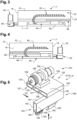
Figure 8 is a longitudinal cross section of the sliding member offigures 5 to 7 , along line VIII-VIII offigure 6 , showing in particular the vacuum chamber and the compressed air passages of the sliding member. -
Figure 9 is a transversal cross section of this sliding member, along line IX-IX offigures 6 and8 . -
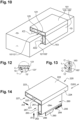
Figure 10 is a perspective view, schematically showing the cooperation of the sliding member offigures 5 to 7 , with the base table offigures 2 to 4 . -
Figure 11 is a perspective view, showing from the bottom the sliding member as illustrated onfigure 10 . -
Figures 12 and 13 are end views, at greater scale, of details XII and XIII offigure 10 . -
Figure 14 is a perspective view, showing a second sliding member which forms part of the high accuracy sliding assembly offigure 1 . -
Figure 15 is a bottom view along arrow XV, analogous tofigure 6 , showing the sliding member offigure 14 . -
Figure 16 is a front view along arrow XVI, analogous tofigure 7 , showing the sliding member offigure 14 . -
Figure 17 is a perspective view, analogous tofigure 11 , schematically showing the cooperation of a sliding member and the base table, which both form part of a sliding assembly according to another embodiment of the invention. -
Figure 18 is a transversal cross section of both the sliding member and the base table offigure 17 , along line XVIII-XVIII offigure 17 . -
Figure 19 is a perspective view, showing from the bottom the sliding member as illustrated onfigure 17 . -
Figure 20 is a front view, showing at greater scale a channel which is part of the lift region of the sliding member. -
Figure 21 is a longitudinal cross-section, illustrating a channel that is said with compressed air by means of several pipes. -
Figure 22 is a longitudinal cross-section, analogous tofigure 8 , along line XXIV offigure 7 . -
Figure 1 illustrates a manufacturing machine, which is referenced 1000 as a whole. Thismachine 1000 is first provided with aframe 1002, substantially composed ofvertical posts 1004 andhorizontal masts 1006 which rest on travellingrollers 1008.Pads 1010 which ensure an anti-vibratory function, are provided at the top of saidframe 1002. Themechanical elements 1002 to 1010 listed in the present paragraph are known as such and do not form part of the invention, so that they will not be described in further detail. - This
machine 1000 further includes a high accuracy sliding assembly, according to the invention, which is referenced I as a whole. Said sliding assembly essentially comprises a so-called base or reference table 1, as well as a first 101 and a second 201 sliding members. This base table, which is shaped as a parallelepiped, has six surfaces defined with reference to the normal use position: - opposite upper 10 and lower 11 surfaces, as well as
- peripheral surfaces, namely opposite
longitudinal surfaces -
Upper surface 10 defines a so-called reference plane P. Moreover, axes X and Z are noted, which are included into said plane P and are parallel respectively to above defined longitudinal surfaces and transversal surfaces. Y axis is also noted, which is perpendicular to both X and Z. - As will be explained hereafter, the above-mentioned sliding
members upper surfaces 10 andperipheral surfaces - For what concerns the chosen material, it is advantageously non-porous and has a crystalline structure. According to a particularly advantageous feature of the invention, at least the
surfaces - The invention also encompasses a base table, which is made of materials that are different from Absolute Black Granite. In this respect, those skilled in the art may choose materials that have a high stability with respect to both mechanical stresses and temperature variations. By way of examples, glass or silicon carbide may be used. However, Absolute Black Granite is the preferred material, in particular due to its relatively low cost.
- According to the invention, at least above-mentioned
surfaces -
Longitudinal surface 12 of the table is equipped with aU-shaped chute 30, which is fixed thereto by any appropriate means. This chute supports acable carrier 32, which enables the passage of several cables and air tubes from the sliding member, as will be described hereafter. - Moreover, said
surface 12 is provided with a fixedlinear motor element 34, which forms a so-called stator. This fixedelement 34 extends over a major part of the Z dimension ofsurface 12. As will be explained in further detail,element 34 is adapted to cooperate with a mobile linear motor element, which is provided on the sliding member. Further, anelongated encoder 36 extends immediately above said fixedelement 34. This encoder, which is known as such, makes it possible to control with a very high accuracy the respective positions of the sliding member and the above-mentioned base table. - The
transversal face 14 of the table is equipped with similar mechanical elements, as those 30 to 36 described immediately above. In this respect, we note 40 the U-shaped chute, 42 the cable carrier, 44 the fixed linear motor element and 46 the respective encoder. - The high accuracy sliding assembly of the invention also incorporates at least one sliding member. In the present embodiment, two distinct sliding
members - The first sliding
member 101 will now be described, in particular with reference tofigures 5 to 13 . Said sliding member is substantially composed of a so-calledload support section 120 and a so-calledguiding section 160, which are shown in an isolated manner onfigure 11 . As will become clearer at reading the following description, load support section is located in use immediately above upper surface of the table, whereas guiding section is located immediately beside peripheral surface of the table. In this first embodiment, guidingsection 160 protrudes downwards from a lateral edge ofload support section 120. In other words, this slidingmember 101, as well as the slidingmember 201 described hereunder, are substantially L shaped. - Said
load support section 120 is manufactured as a hollow body. With reference to its normal use position, as well as to the motion direction D101 of slidingmember 101, the following constitutive parts of thissection 120 are noted: - opposite lower 121 and upper 122 walls
- opposite
inner side wall 123 andouter side wall 124, which are respectively adjacent and opposite to table 1 -
longitudinal reinforcement ribs - It is further to be noted that opposite
longitudinal ends section 120 are both opened, namely they are not provided with a solid closing. - Said guiding
section 160 has a structure, which is substantially similar to that ofsection 120. In an analogous way, the following constitutive parts of thissection 160 are noted - opposite upper 161 and lower 162 walls
- opposite
inner side wall 163 andouter side wall 164, which are respectively adjacent and opposite to table 1. - Opposite longitudinal ends 167 and 168 of
section 160 are opened. However, in the present embodiment,section 160 is not provided with ribs since it is not submitted with load. - Advantageously, the chosen material for both
sections member - Hollow bodies, respectively forming
section member 101. - According to an advantageous feature of the invention, at least lower surface 121' of
lower wall 121 part ofsection 120, as well as inner surface 163' ofwall 163 part ofsection 160, are submitted to an optical flatness treatment. Typically, this treatment is substantially analogous to that of table 1, such as above described. - The following numerical values are noted, some of them being referenced on the figures:
- L120, namely length of
section 120 - w120, namely width of
section 120 - t121: thickness of
wall 121, bearing in mind that the thickness ofother walls 122 to 124 is analogous - L160, namely length of
section 160 - h160, namely height of
section 160 - t161: thickness of
wall 161, bearing in mind that the thickness ofother walls 162 to 164 is analogous. - Those skilled in the art will be in a position to set the above dimensions of the sliding members, depending upon different parameters. In particular, the dimensions along the longitudinal axis will be adjusted as a function of the load supported by the sliding member. Moreover, the dimensions along the vertical axis will be adjusted to minimise the yaw parameter, in particular as a function of the load and the displacement speed of the sliding member. In the present embodiment, the length of guiding
section 160 is superior to that ofload support section 120 bearing in mind that, as a variant, the load support section might be longer. - An essential feature of the invention will now be described, in particular with reference to
figures 8 to 10 . According to this feature, bothlower wall 121 andinner wall 163 are divided into three functional regions. Referring tofigure 8 ,lower wall 121 comprises two opposite so-calledextremity regions intermediate region 140. As will become clearer at reading the following description,regions load support section 120, whereasregion 140 is a pre-load region ofsection 120. - In each
lift region lower wall 121 is drilled with a single passage respectively referenced 131 and 136. At its upstream end, each passage leads to arespective pipe common hole 139, which is provided in theupper wall 122. At their respective downstream end,passage 131 ofregion 130 leads to afirst channel 133, whereaspassage 136 ofother region 135 leads to asecond channel 138. - According to a particularly advantageous feature of the invention, each channel is elongated, while extending transversely with respect to the motion of the slider. This elongated shape is illustrated on
figure 20 , wherein the length L133 and the width W133 ofchannel 133 are referenced. Advantageously, the ratio (W133/L133) between this width and this length is between 3% and 10%. - In the above embodiment, each channel is fed by one single pipe. In a variant illustrated on
figure 21 , one given channel may be fed by several pipes, which are provided regularly along the length of this channel. This variant is advantageous, for bringing better regularity in pulse air pressure. - In
preload region 140, lower surface 121' oflower wall 121 is provided with recesses, which formcavities arche 143, whereas asolid zone 144 is located on the edge ofsection 120 which is attached tosection 160. The manufacturing of each cavity is carried out in a way known as such. By way of example, the depth of these cavities, respectively noted d141 and d142, is between 1 mm and 5 mm. - The areas of these
cavities - According to the invention, the global area of these cavities, namely the sum S141 + S142, represents between 40 and 95%, advantageously between 60 and 90% of the whole area S'120 of active surface 120' part of
load support section 120. Those skilled in the art will be in a position to modify this proportion, within the above ranges, depending upon several parameters such as those above described, namely the load and the displacement speed. Each cavity leads to arespective passage 145 and 146, drilled inlower wall 121. Said passages lead in turn to pipes are respectively noted 147 and 148, which extend in the above-mentionedhole 139. - On
figure 6 let us note W141 the so-called transverse dimension, with respect to the motion of the slider, of eachcavity channel 133, which can also be seen onfigure 6 . It is to be noted that this length is also a transverse dimension, according to the above definition. The technical effect of this feature allows the compressed air to be equally spread around the channels. -
Different pipes load support section 120, and are received in thecable sleeve 32.Pipes figure 8 , whereasother pipes figure 9 . Both compressed air source and vacuum source, which are schematically illustrated on the figures, are known as such. The respective values of compressed air and vacuum will be further described, with reference to the implementation method according to the invention. -
Load support section 120 is also equipped with functional accessories, which are not part of the invention. In the present embodiment, these accessories make it possible to manufacture optical workpieces. In this respect, they comprise aflange 150, which is fixed to upper wall ofload support section 120 by any appropriate means, in particular by screwing intosection 120. This flange supports aspindle 152 which is provided with a clampingjaw 154, which is adapted to maintain a not shown workpiece. - As above mentioned, the mechanical structure of guiding
section 160 is substantially similar to that ofload support section 120. In this respect the mechanical elements ofsection 160, which are analogous to that ofsection 120, are given the same references added bynumber 40. It is to be noted that, insection 160, the twocavities like cavities passages 173, 173', as well as 178, 178' are provided the one behind the other. - As shown on
figure 22 , the guidingsection 160 comprises twoend lift regions load support section 120. However, thecavities section 160 comprises twointermediate preload regions - Moreover, guiding section is equipped with guiding accessories, which are adapted to cooperate with some mechanical elements provided on table 1. In this respect said
section 160 comprises a so-called mobilelinear motor member 190, intended to cooperate with the fixedlinear motor element 34. In addition, said guiding section is provided with at least one sensor, which is adapted to cooperate with theelongated encoder 36. The present embodiment encompasses two of such sensors, the first one 192 being intended for normal use whereas theother one 193 is intended to a potential emergency use. At last, this guiding section is equipped with twolimit switches above elements 190 to 195 are known as such, so that they will not be described in further details. - Sliding
member 201 has a structure, which is globally similar to that of above described slidingmember 101. In particular it comprises two different sections, namely aload support section 220 and aguiding section 260. More in detail the mechanical elements of slidingmember 201, which are analogous to that of slidingmember 101, are given the same references added by number 100. -
Member 201 differs from that 101, in particular in that itsload support section 220 is longer than itsguiding section 260, whereas the above-describedload support section 120 is shorter than guidingsection 160.Load support section 220 is provided with functional accessories, which aretools 250 to 254 shown onfigure 1 . These tools, which are known as such and thus will not be further described, are intended to the processing of a not shown blank which is received in thespindle 152. - The implementation of sliding
member 201 is substantially identical to that of slidingmember 101. In particular, as shown onfigures 15 and 16 , this slidingmember 201 is provided withactive surfaces 221' and 263'. The latter cooperate with the complementary active surfaces 10' and 14' of the table, in the same manner as the cooperation between active surfaces 121' and 163' with the complementary active surfaces 10' and 12'. - A way of implementing the sliding assembly I according to the invention, as well as the
machine 1000 equipped with this sliding assembly, will now be explained. This implementation includes displacing each slidingmember member 101 will now be described, bearing in mind that the displacement of the other slidingmember 201 is analogous. - Compressed air is first fed into
passages lower wall 121, as well as intopassages inner wall 163. As a result, this compressed air leads to liftregions cavities - The combination of compressed air injection and vacuum creation, as described above, makes it possible to maintain active surfaces 122' and 163' slightly above complementary active surfaces of the table. As illustrated on
figures 12 and 13 , clearances C and C' are thus created between each active surface and its respective complementary surface. By way of example, the nominal value of each clearance is between 1 micron and 5 microns. - In an advantageous manner, this clearance value is monitored, in a way known as such. If a measured instantaneous value is outside a predetermined range, the value of at least one of compressed air and vacuum is modified. In practice, the value of compressed air is typically unchanged, whereas the operator may modify the value of the vacuum. In this respect, if the instantaneous measured clearance is too low, the vacuum value is lowered. On the other end, if this measure clearance is too high, then the vacuum value is increased.
- Sliding
members machine 1000 may also be implemented, in a way known as such. In use, the respective motions of two slidingmembers tools 250 to 254 is actuated, so as to process the blank held byspindle 152. - The invention brings about several substantial advantages, with respect to previously described prior art.
- First it is to be noted that the applicant has identified the drawbacks of prior sliding assemblies, in terms of motion. Indeed, in a typical sliding assembly, the basic mechanical principle is as follows: maintaining the sliding member with a more or less predetermined clearance with respect to the table, so as both to permit its displacement and to avoid any mutual disengagement of this sliding member and of this table. This distance shall be as little as possible, in order to guarantee a high accuracy. However, this distance shall be sufficient to avoid any jamming of the sliding member.
- With that in mind, the applicant has shed light on the fact that prior systems are essentially hyperstatic, which constitutes a significant drawback. These prior art systems all use sliding members with at least three active surfaces, which define respective air-stages. Under these circumstances, it is necessary to provide a relatively substantial clearance between these active surfaces of the sliding members and the complementary active surfaces of the table. Thus, providing a thinner clearance between these surfaces would unduly increase the risks of jamming between the sliding member and the table. As a conclusion, the above mentioned substantial clearance might be considered as a necessary feature of prior art, which brings about a poor accuracy. In particular no prior sliding assembly, equipped with air bearings, makes it possible to reach a high accuracy, which could be compared to that provided by oil bearings.
- On the contrary, the invention is based on the use of only two active surfaces, provided respectively on the load support section and on the guiding section. This feature makes it possible to render the whole assembly substantially isostatic, which is particularly advantageous with respect to hyperstatic prior art solutions. Indeed, this isostaticity substantially reduces the risks of jamming. Moreover, the sliding member is maintained with respect to table, in a satisfactory manner. In this respect, providing the preload vacuum region guarantees this maintaining, while creating a controlled clearance which enables the required accuracy.
- In addition to the provision of the only two active surfaces, such as described immediately above, the invention rests upon also a specific arrangement between lift regions and preload region. Indeed, load support section as well as guiding section are both provided first with two end lift regions, at their opposite ends. Moreover at least one preload region is provided in an intermediate position, also for each of these sections, namely between the above opposite lift regions. This arrangement between said regions, typically formed by channels and at least one cavity, is particularly advantageous since the orthogonal construction of the granite and the slides form an isometrical mechanical assembly.
- It is to be noted that this arrangement brings about technical effects with respect to potential alternative arrangements between lift regions and preload regions, which are not part of the invention.
- Let us consider a first potential arrangement of a mid-preload region and of a lift region, such as a compressed air nozzle, which is provided at one single end of the slider. Let us also consider a second potential arrangement of a mid-preload region and of opposite lift regions, which are provided on one single section, namely only the load support section or only the guiding section. The above detailed arrangement, according to the invention, has specific advantages with respect to these two potential arrangements which are not functional, in particular due to their lack of stability.
- In addition, the transverse elongated shape of the channels makes it possible to strengthen the above technical effects. In particular this shape confers a very high stability to the motion of the slider.
-
Figures 17 to 19 illustrate a second embodiment of a sliding assembly according to the invention, which is denoted as a whole by reference II. On thesefigures 17 to 19 the mechanical elements, which are analogous to that of the first embodiment, are given the same references added by number 300. - First the base table 301 of this second embodiment is different from that 1, which has been above described. Indeed, this table 301 is provided with a groove which is denoted as a whole by
reference 350. Advantageously, as shown in particular onfigure 17 , this groove leads to both oppositetransversal surfaces groove 350 is substantially U shaped, namely it has ahorizontal bottom 352, as well as twovertical edges upper surface 310. - Moreover, sliding
member 401 differs from that 101, in particular in that it is substantially T shaped. Indeed, itsguiding section 460 protrudes downwards from a mid-zone ofload support section 420. In use, this guiding section is adjacent to onesingle edge 354 of the groove, whereas it is distant from theother edge 356. - Several accessories, which are part of the sliding assembly are accommodated in this groove. For what concerns the non-mobile assemblies, fixed
linear motor element 334 is first provided on afirst edge 354 of the groove. Moreover,cable sleeve 332, which is schematically illustrated, is also located in this groove. Finally,encoder 336 is provided on theopposite edge 356. - For what concerns moving assemblies,
sensor 492, which is adapted to cooperate with anencoder 336, is fixed onto the lower wall ofload support section 420. Moreover, mobilelinear motor element 490, which is adapted to cooperate with above-mentionedfixed element 334, is fixed onto lower wall of guiding section, by a connectingplate 491 or analogous. - The implementation of sliding
member 401 is substantially similar to that of slidingmember 101, as explained here above. On the one hand, the active surface 421' of theload support section 420 slides along the complementary active surface 310' of the table, the same way as above active surfaces 121' and 221' cooperate with complementary active surface 10'. On the other hand, the active surface 463' of the guidingsection 460 slides along the complementary active surface 354' of the table, the same way as aboveactive surfaces 163' and 263' cooperate with respective complementary active surfaces 12' and 14'. - In the present description, two different embodiments of the invention have been detained. Each of these embodiments bring about specific advantages.
- The first embodiment, which incorporates an L shaped sliding member, permits the use of a parallelepiped base table. Therefore, this embodiment makes it possible to ease the manufacturing of this table.
- The second embodiment incorporates a T shaped sliding member, which is located at a close vicinity with respect to the gravity center of the base table. This makes it possible to reduce the global length of the sliding member. Moreover, the groove, provided in the table, enables the reception of accessories which are part of the sliding assembly. Under these circumstances, the global dimensions of this assembly are reduced. Moreover, the accessories accommodated in this groove benefit of a higher protection, in particular with respect to potential external impacts. In this respect, the
load support section 420 may be covered with a protectingbellow 429, of any appropriate type. - Providing a horizontal load support section, combined with a vertical guiding section, is an especially advantageous feature of the invention. As this has been mentioned above, this makes it possible to independently set the dimensions of these sections, so as to control respectively the load and the yaw parameters. In particular, one of these sections might be either shorter or longer than the other one. In this respect emphasis shall be laid on the fact that, in prior art, no sliding member is equipped with two different sections which respectively extend horizontally and vertically. Moreover none of these prior sliding members is equipped with sections, the respective lengths thereof are different.
- Let us finally emphasise a particularly advantageous feature of the invention. As shown on the different described embodiments, on each longitudinal side, with respect to the motion of the slider, each cavity is associated with one single transversal channel. This feature may apply for different arrangements:
- on
figure 6 , twocavities left channel 133 and with one singleright channel 138; - on
figure 7 , twocavities left channel 173 and with one single right channel 173', whereas 182 is provided with one single left channel 178' and with one singleright channel 178, - on
figure 15 , an arrangement which is similar tofigure 6 : twocavities left channel 233 and with one singleright channel 238; - on
figure 16 , onesingle cavity 281 with one singleleft channel 273 and one singleright channel 278; - on
figure 19 , an arrangement which is similar tofigures 6 and15 : twocavities left channel 433 and with one singleright channel 438; - on
figure 19 , onesingle cavity 481 with one singleleft channel 473 and one singleright channel 478. - This combination, for each cavity, between said cavity and two transversal channels on either side, brings about significant advantages with respect to stability of the motion. In particular it substantially avoids any vibrations, compared to other embodiments.
Claims (15)
- A sliding assembly (I; II), in particular for a manufacturing machine, said machine being intended to manufacture workpieces, such as optical workpieces, as mirrors, lenses, contact lenses or intraocular lenses,said sliding assembly comprising:- a base table (1; 301)- at least one sliding member (101, 201; 401) which is movable with respect to said table,- moving means (34, 44, 190; 334, 490) adapted to move each said sliding member with respect to said table,characterised in thateach sliding member is provided with only one single so-called first active surface (121'; 421') and one single so-called second (163'; 463') active surface, said single first active surface and said single second active surface being mutually perpendicular, said sliding member comprising- a load support section (120; 420) being provided on the first active surface, said load support section being adapted to slide along a first complementary active surface (10'; 310') of said table, in particular an upper surface of said table and- a guiding section (160; 460) being provided on the second active surface, guiding section being adapted to slide along a second complementary active surface (12'; 354') of said table, in particular a peripheral surface of the table, said second complementary active surface being located in use underneath said first complementary active surfaceeach of said load support section and guiding section comprising, with reference to the motion direction of the sliding member along the table- a first extremity lift region (130; 180) being provided at a first extremity of said section (120 or 160), as well as an opposite extremity lift region (135; 185), being provided at the opposite extremity of said section, each lift region being adapted to be connected to a compressed air source (AIR)- at least one intermediate preload region (140; 1400, 1401), being provided between said opposite extremity lift regions, each preload region being adapted to be connected to a vacuum source (VAC), wherein said intermediate preload region comprises at least one cavity (141,142; 441,442) provided in the active surface, said cavity being adapted to be connected to said vacuum source, and wherein the total area (S141+S142) of said cavity(ies) is between 40 and 95 % of the total area of said active surface which is provided with said cavity(ies).
- A sliding assembly according to preceding claim wherein, in use, said load support section and said first active surface extend both horizontally, so as to be dimensioned in order to control the load, whereas said guiding section and said second active surface extend both vertically, so as to be dimensioned in order to control the yaw.
- A sliding assembly according to any preceding claim, wherein each lift region comprises at least one air diffusion channel (133,138; 433,438), said air diffusion channel being adapted to be connected with the compressed air source, each air diffusion channel being elongated and extending transversely with reference to the motion direction of the sliding member along the table.
- A sliding assembly according to preceding claim, wherein the ratio between the width (W133) of the channel and the length (L133) of said channel is between 3% and 10%, in particular between 3% and 5%.
- A sliding assembly according to claim 3 or 4, wherein said lift region comprises at least one passage (131) which leads into said channel (133), said passage being adapted to receive a pipe for connection to the compressed air source, in particular several passages (1130 - 1334) which are provided regularly along the length of one single channel.
- A sliding assembly according to any preceding claim, wherein the depth of each cavity is between 1 mm and 5 mm.
- A sliding assembly according to any preceding claim, wherein the total area (S141+S142) of said cavity(ies) is between 60 and 90 % of the total area of said active surface which is provided with said cavity(ies).
- A sliding assembly according to any of claims 3 to 5, in combination with claim 6 or 7, wherein the transverse dimension (W141), with respect to the motion direction, of each cavity is superior to the transverse dimension (L133) of each channel.
- A sliding assembly according to any preceding claim, comprising at least two preload regions (1400, 1401) the one behind the other with respect to the motion direction, as well as at least one intercalary lift region (180', 185') provided between said preload regions, each intercalary lift region comprising one single diffusion channel (173', 178').
- A sliding assembly according to any preceding claim, wherein at least the active surfaces of both load support section and guiding section, as well as the complementary active surfaces of base table, are optically polished, and wherein said sliding member is made of optical flatness ceramic, in particular a substantially non-porous ceramic and/or wherein at least the active surfaces of the tables are made of substantially nonporous Absolute Black Granite.
- A sliding assembly according to any preceding claim, wherein said moving means comprise a fixed linear motor element (34,334) provided on one of said base table and said sliding member, as well as a mobile linear motor element (190; 490) provided on the other of said base table and said sliding member, said assembly further comprising positioning means adapted to control the mutual position of sliding member with respect to the base table, said positioning means comprising in particular an encoder provided on one of said base table and said sliding member, as well as a sensor provided on the other of said base table and said sliding member.
- A sliding assembly according to any claims 3 to 11 wherein, on either side of each cavity, with respect to the motion direction, one single air diffusion channel is provided (141 - 133,138 ; 142 - 133,138 ; 181 - 173,173'; 182 -178,178'; 241 - 233,238 ; 242 - 233,238 ; 442 - 433,438 ; 481 - 473,478).
- A sliding assembly according to any preceding claim, wherein said sliding member (101, 201) is L shaped, said guiding section (160) protruding from a lateral edge of load support section (120), or wherein said sliding member (401) is T shaped, said guiding section (460) protruding from a mid-part of load support section (420).
- A sliding assembly according to claim 13, wherein said guiding section is at least partly received in a groove (350) provided in said base table, said groove accommodating at least one further accessory of said guiding assembly, such as at least part of moving means, at least part of positioning means, at least part of a cable sleeve.
- A manufacturing machine for manufacturing workpieces, in particular optical workpieces, said machine comprising a frame, a sliding assembly (I; II) according to any preceding claim, which is mounted on said frame, as well as manufacturing means mounted on said sliding assembly,
wherein said sliding assembly comprises- a first sliding member (101) which is movable with respect to said table, along a first Z direction, said first sliding member being provided with support means adapted to support workpieces;- a second sliding member (201) which is movable with respect to said table, along a second X direction, which is in particular perpendicular with respect to said first direction, said second sliding member being provided with at least one manufacturing tool; and- possibly a vertical sliding member which is movable with respect to said table, along a third Y direction, which is in particular perpendicular with respect to said first direction, said third sliding element being provided with at least one manufacturing tool.
Applications Claiming Priority (1)
| Application Number | Priority Date | Filing Date | Title |
|---|---|---|---|
| EP20190394.5A EP3954497A1 (en) | 2020-08-11 | 2020-08-11 | High accuracy sliding assembly for a manufacturing machine, and manufacturing machine comprising at least one such assembly |
Publications (3)
| Publication Number | Publication Date |
|---|---|
| EP3954498A1 EP3954498A1 (en) | 2022-02-16 |
| EP3954498B1 true EP3954498B1 (en) | 2023-07-19 |
| EP3954498C0 EP3954498C0 (en) | 2023-07-19 |
Family
ID=72380883
Family Applications (2)
| Application Number | Title | Priority Date | Filing Date |
|---|---|---|---|
| EP20190394.5A Withdrawn EP3954497A1 (en) | 2020-08-11 | 2020-08-11 | High accuracy sliding assembly for a manufacturing machine, and manufacturing machine comprising at least one such assembly |
| EP21190621.9A Active EP3954498B1 (en) | 2020-08-11 | 2021-08-10 | High accuracy sliding assembly for a manufacturing machine, and manufacturing machine comprising at least one such assembly |
Family Applications Before (1)
| Application Number | Title | Priority Date | Filing Date |
|---|---|---|---|
| EP20190394.5A Withdrawn EP3954497A1 (en) | 2020-08-11 | 2020-08-11 | High accuracy sliding assembly for a manufacturing machine, and manufacturing machine comprising at least one such assembly |
Country Status (2)
| Country | Link |
|---|---|
| EP (2) | EP3954497A1 (en) |
| ES (1) | ES2952238T3 (en) |
Family Cites Families (17)
| Publication number | Priority date | Publication date | Assignee | Title |
|---|---|---|---|---|
| US6140815A (en) * | 1998-06-17 | 2000-10-31 | Dover Instrument Corporation | High stability spin stand platform |
| US6499880B2 (en) * | 1999-02-19 | 2002-12-31 | Nikon Corporation | Static pressure air bearing |
| JP2001173654A (en) * | 1999-12-15 | 2001-06-26 | Nikon Corp | Hydrostatic bearing device and optical device using the same |
| US6628435B1 (en) * | 2000-07-18 | 2003-09-30 | Creo Srl | Contact-less ballistic scanning method |
| JP2002252166A (en) | 2001-02-27 | 2002-09-06 | Canon Inc | Stage apparatus, exposure apparatus, device manufacturing method, and movement guiding method |
| DE10251228C1 (en) * | 2002-11-04 | 2003-11-20 | Siemens Ag | Machine base for precision machine tool has guide surfaces for mountings formed directly by smooth surfaces of polymer concrete casting |
| JP4146825B2 (en) * | 2003-08-27 | 2008-09-10 | エーエスエムエル ネザーランズ ビー.ブイ. | Lithographic apparatus, device manufacturing method, and slide assembly |
| JP4498272B2 (en) * | 2005-12-28 | 2010-07-07 | エーエスエムエル ネザーランズ ビー.ブイ. | Lithographic apparatus, reticle masking device of a lithographic apparatus, gas bearing, and apparatus having such a gas bearing |
| US7642523B1 (en) | 2006-05-02 | 2010-01-05 | New Way Machine Components, Inc. | Vacuum chamber stage with application of vacuum from below |
| JP5235893B2 (en) * | 2007-10-19 | 2013-07-10 | ボッシュ株式会社 | Hydrostatic slide device and grinding device provided with static pressure slide device |
| DE102008019681B4 (en) | 2008-04-11 | 2013-10-17 | Fraunhofer-Gesellschaft zur Förderung der angewandten Forschung e.V. | By means of aerostatic bearing elements guided table for vacuum application |
| JP2013096445A (en) * | 2011-10-28 | 2013-05-20 | Jtekt Corp | Variable throttle type static-pressure bearing |
| KR20150086309A (en) | 2012-11-20 | 2015-07-27 | 뉴 웨이 머신 컴포넌츠, 인코포레이티드 | Air bearing for use as seal |
| JP6171318B2 (en) * | 2012-12-04 | 2017-08-02 | 株式会社ジェイテクト | Hydrostatic fluid guide device and machine tool using hydrostatic fluid guide device |
| US8899887B2 (en) * | 2013-02-13 | 2014-12-02 | Interdyne Systems Inc. | Drilling apparatus with a decoupled force frame and metrology frame for enhanced positioning |
| EP3670067B1 (en) * | 2018-12-20 | 2022-07-27 | Etel S.A. | Positioning device in portal design |
| CN110000573A (en) * | 2019-05-08 | 2019-07-12 | 盐城盐东速削科技有限公司 | A kind of movable beam type speed based on magnetic levitation technology cuts machine |
-
2020
- 2020-08-11 EP EP20190394.5A patent/EP3954497A1/en not_active Withdrawn
-
2021
- 2021-08-10 EP EP21190621.9A patent/EP3954498B1/en active Active
- 2021-08-10 ES ES21190621T patent/ES2952238T3/en active Active
Also Published As
| Publication number | Publication date |
|---|---|
| EP3954497A1 (en) | 2022-02-16 |
| ES2952238T3 (en) | 2023-10-30 |
| EP3954498A1 (en) | 2022-02-16 |
| EP3954498C0 (en) | 2023-07-19 |
Similar Documents
| Publication | Publication Date | Title |
|---|---|---|
| Bryan | Design and construction of an ultraprecision 84 inch diamond turning machine | |
| CN1958227B (en) | Fast tool arrangement for lathes for machining optical workpieces | |
| KR101430047B1 (en) | Saddle for gantry roader and the gantry roader using the same | |
| EP1072353B1 (en) | Metal plate cutting machine | |
| CN111936300B (en) | Build platform guide for additive manufacturing equipment | |
| CN101195178A (en) | Gantry type ultra-precision fly cutting milling machine | |
| Leadbeater et al. | A unique machine for grinding large, off-axis optical components: the OAGM 2500 | |
| GB2135916A (en) | Xy table for machine operations | |
| Sriyotha et al. | Development of 5-axis linear motor driven super-precision machine | |
| WO2023077860A1 (en) | Composite coordinate measurement instrument | |
| EP3954498A1 (en) | High accuracy sliding assembly for a manufacturing machine, and manufacturing machine comprising at least one such assembly | |
| CN121382795A (en) | Dynamic adjustable air floatation linear guide rail and adjusting method thereof | |
| CN103481112A (en) | Method for synchronously adjusting balance of transverse beam of numerical-control gantry machine tool with movable beam | |
| CN103698984B (en) | A kind of superfinishing scanning plated film and location lithographic equipment | |
| US20220226083A1 (en) | Dental machine tool | |
| US20050073203A1 (en) | Stage for a workpiece | |
| Chang et al. | Development of a compact ultra-precision six-axis hybrid micro-machine | |
| CN218935782U (en) | Three-coordinate measuring instrument stable in movement | |
| Yoshioka et al. | Design Concept and Structural Configuration of Advanced Nano-Pattern Generator with Large Work Area" ANGEL". | |
| CN111360555A (en) | An automatic compensation mechanism for ultra-precision machine tools suitable for large-size workpieces | |
| Ohmori et al. | An ultraprecision on-machine measurement system | |
| CN220462236U (en) | High-precision sliding mechanism | |
| KR100728285B1 (en) | Reciprocating support structure of machine tool | |
| CN121403226B (en) | Precise grinding and polishing machine tool and processing method thereof | |
| CN2592654Y (en) | Die laser surface treatment numerical control machine |
Legal Events
| Date | Code | Title | Description |
|---|---|---|---|
| PUAI | Public reference made under article 153(3) epc to a published international application that has entered the european phase |
Free format text: ORIGINAL CODE: 0009012 |
|
| STAA | Information on the status of an ep patent application or granted ep patent |
Free format text: STATUS: THE APPLICATION HAS BEEN PUBLISHED |
|
| AK | Designated contracting states |
Kind code of ref document: A1 Designated state(s): AL AT BE BG CH CY CZ DE DK EE ES FI FR GB GR HR HU IE IS IT LI LT LU LV MC MK MT NL NO PL PT RO RS SE SI SK SM TR |
|
| STAA | Information on the status of an ep patent application or granted ep patent |
Free format text: STATUS: REQUEST FOR EXAMINATION WAS MADE |
|
| 17P | Request for examination filed |
Effective date: 20220816 |
|
| RBV | Designated contracting states (corrected) |
Designated state(s): AL AT BE BG CH CY CZ DE DK EE ES FI FR GB GR HR HU IE IS IT LI LT LU LV MC MK MT NL NO PL PT RO RS SE SI SK SM TR |
|
| GRAP | Despatch of communication of intention to grant a patent |
Free format text: ORIGINAL CODE: EPIDOSNIGR1 |
|
| STAA | Information on the status of an ep patent application or granted ep patent |
Free format text: STATUS: GRANT OF PATENT IS INTENDED |
|
| RAP1 | Party data changed (applicant data changed or rights of an application transferred) |
Owner name: C2'M INVEST |
|
| RIN1 | Information on inventor provided before grant (corrected) |
Inventor name: MEUNIER, PATRICK |
|
| INTG | Intention to grant announced |
Effective date: 20230414 |
|
| GRAS | Grant fee paid |
Free format text: ORIGINAL CODE: EPIDOSNIGR3 |
|
| GRAA | (expected) grant |
Free format text: ORIGINAL CODE: 0009210 |
|
| STAA | Information on the status of an ep patent application or granted ep patent |
Free format text: STATUS: THE PATENT HAS BEEN GRANTED |
|
| AK | Designated contracting states |
Kind code of ref document: B1 Designated state(s): AL AT BE BG CH CY CZ DE DK EE ES FI FR GB GR HR HU IE IS IT LI LT LU LV MC MK MT NL NO PL PT RO RS SE SI SK SM TR |
|
| REG | Reference to a national code |
Ref country code: GB Ref legal event code: FG4D |
|
| REG | Reference to a national code |
Ref country code: CH Ref legal event code: EP |
|
| REG | Reference to a national code |
Ref country code: DE Ref legal event code: R096 Ref document number: 602021003563 Country of ref document: DE |
|
| REG | Reference to a national code |
Ref country code: IE Ref legal event code: FG4D |
|
| U01 | Request for unitary effect filed |
Effective date: 20230810 |
|
| U07 | Unitary effect registered |
Designated state(s): AT BE BG DE DK EE FI FR IT LT LU LV MT NL PT SE SI Effective date: 20230817 |
|
| REG | Reference to a national code |
Ref country code: ES Ref legal event code: FG2A Ref document number: 2952238 Country of ref document: ES Kind code of ref document: T3 Effective date: 20231030 |
|
| REG | Reference to a national code |
Ref country code: LT Ref legal event code: MG9D |
|
| U20 | Renewal fee for the european patent with unitary effect paid |
Year of fee payment: 3 Effective date: 20231127 |
|
| PG25 | Lapsed in a contracting state [announced via postgrant information from national office to epo] |
Ref country code: GR Free format text: LAPSE BECAUSE OF FAILURE TO SUBMIT A TRANSLATION OF THE DESCRIPTION OR TO PAY THE FEE WITHIN THE PRESCRIBED TIME-LIMIT Effective date: 20231020 |
|
| PG25 | Lapsed in a contracting state [announced via postgrant information from national office to epo] |
Ref country code: IS Free format text: LAPSE BECAUSE OF FAILURE TO SUBMIT A TRANSLATION OF THE DESCRIPTION OR TO PAY THE FEE WITHIN THE PRESCRIBED TIME-LIMIT Effective date: 20231119 |
|
| PG25 | Lapsed in a contracting state [announced via postgrant information from national office to epo] |
Ref country code: RS Free format text: LAPSE BECAUSE OF FAILURE TO SUBMIT A TRANSLATION OF THE DESCRIPTION OR TO PAY THE FEE WITHIN THE PRESCRIBED TIME-LIMIT Effective date: 20230719 Ref country code: NO Free format text: LAPSE BECAUSE OF FAILURE TO SUBMIT A TRANSLATION OF THE DESCRIPTION OR TO PAY THE FEE WITHIN THE PRESCRIBED TIME-LIMIT Effective date: 20231019 Ref country code: IS Free format text: LAPSE BECAUSE OF FAILURE TO SUBMIT A TRANSLATION OF THE DESCRIPTION OR TO PAY THE FEE WITHIN THE PRESCRIBED TIME-LIMIT Effective date: 20231119 Ref country code: HR Free format text: LAPSE BECAUSE OF FAILURE TO SUBMIT A TRANSLATION OF THE DESCRIPTION OR TO PAY THE FEE WITHIN THE PRESCRIBED TIME-LIMIT Effective date: 20230719 Ref country code: GR Free format text: LAPSE BECAUSE OF FAILURE TO SUBMIT A TRANSLATION OF THE DESCRIPTION OR TO PAY THE FEE WITHIN THE PRESCRIBED TIME-LIMIT Effective date: 20231020 |
|
| PG25 | Lapsed in a contracting state [announced via postgrant information from national office to epo] |
Ref country code: PL Free format text: LAPSE BECAUSE OF FAILURE TO SUBMIT A TRANSLATION OF THE DESCRIPTION OR TO PAY THE FEE WITHIN THE PRESCRIBED TIME-LIMIT Effective date: 20230719 |
|
| REG | Reference to a national code |
Ref country code: DE Ref legal event code: R097 Ref document number: 602021003563 Country of ref document: DE |
|
| PG25 | Lapsed in a contracting state [announced via postgrant information from national office to epo] |
Ref country code: SM Free format text: LAPSE BECAUSE OF FAILURE TO SUBMIT A TRANSLATION OF THE DESCRIPTION OR TO PAY THE FEE WITHIN THE PRESCRIBED TIME-LIMIT Effective date: 20230719 Ref country code: RO Free format text: LAPSE BECAUSE OF FAILURE TO SUBMIT A TRANSLATION OF THE DESCRIPTION OR TO PAY THE FEE WITHIN THE PRESCRIBED TIME-LIMIT Effective date: 20230719 Ref country code: CZ Free format text: LAPSE BECAUSE OF FAILURE TO SUBMIT A TRANSLATION OF THE DESCRIPTION OR TO PAY THE FEE WITHIN THE PRESCRIBED TIME-LIMIT Effective date: 20230719 Ref country code: SK Free format text: LAPSE BECAUSE OF FAILURE TO SUBMIT A TRANSLATION OF THE DESCRIPTION OR TO PAY THE FEE WITHIN THE PRESCRIBED TIME-LIMIT Effective date: 20230719 Ref country code: MC Free format text: LAPSE BECAUSE OF FAILURE TO SUBMIT A TRANSLATION OF THE DESCRIPTION OR TO PAY THE FEE WITHIN THE PRESCRIBED TIME-LIMIT Effective date: 20230719 |
|
| REG | Reference to a national code |
Ref country code: IE Ref legal event code: MM4A |
|
| PLBE | No opposition filed within time limit |
Free format text: ORIGINAL CODE: 0009261 |
|
| STAA | Information on the status of an ep patent application or granted ep patent |
Free format text: STATUS: NO OPPOSITION FILED WITHIN TIME LIMIT |
|
| 26N | No opposition filed |
Effective date: 20240422 |
|
| PG25 | Lapsed in a contracting state [announced via postgrant information from national office to epo] |
Ref country code: IE Free format text: LAPSE BECAUSE OF NON-PAYMENT OF DUE FEES Effective date: 20230810 |
|
| PG25 | Lapsed in a contracting state [announced via postgrant information from national office to epo] |
Ref country code: IE Free format text: LAPSE BECAUSE OF NON-PAYMENT OF DUE FEES Effective date: 20230810 |
|
| U20 | Renewal fee for the european patent with unitary effect paid |
Year of fee payment: 4 Effective date: 20240902 |
|
| U1N | Appointed representative for the unitary patent procedure changed after the registration of the unitary effect |
Representative=s name: IXAS CONSEIL; FR |
|
| REG | Reference to a national code |
Ref country code: CH Ref legal event code: PL |
|
| PG25 | Lapsed in a contracting state [announced via postgrant information from national office to epo] |
Ref country code: CH Free format text: LAPSE BECAUSE OF NON-PAYMENT OF DUE FEES Effective date: 20240831 |
|
| PG25 | Lapsed in a contracting state [announced via postgrant information from national office to epo] |
Ref country code: CY Free format text: LAPSE BECAUSE OF FAILURE TO SUBMIT A TRANSLATION OF THE DESCRIPTION OR TO PAY THE FEE WITHIN THE PRESCRIBED TIME-LIMIT; INVALID AB INITIO Effective date: 20210810 |
|
| PG25 | Lapsed in a contracting state [announced via postgrant information from national office to epo] |
Ref country code: HU Free format text: LAPSE BECAUSE OF FAILURE TO SUBMIT A TRANSLATION OF THE DESCRIPTION OR TO PAY THE FEE WITHIN THE PRESCRIBED TIME-LIMIT; INVALID AB INITIO Effective date: 20210810 |
|
| U20 | Renewal fee for the european patent with unitary effect paid |
Year of fee payment: 5 Effective date: 20250901 |
|
| PGFP | Annual fee paid to national office [announced via postgrant information from national office to epo] |
Ref country code: GB Payment date: 20250916 Year of fee payment: 5 |
|
| PG25 | Lapsed in a contracting state [announced via postgrant information from national office to epo] |
Ref country code: TR Free format text: LAPSE BECAUSE OF FAILURE TO SUBMIT A TRANSLATION OF THE DESCRIPTION OR TO PAY THE FEE WITHIN THE PRESCRIBED TIME-LIMIT Effective date: 20230719 |
|
| PGFP | Annual fee paid to national office [announced via postgrant information from national office to epo] |
Ref country code: ES Payment date: 20251030 Year of fee payment: 5 |