EP3954443A1 - Device having plural markers - Google Patents
Device having plural markers Download PDFInfo
- Publication number
- EP3954443A1 EP3954443A1 EP20787365.4A EP20787365A EP3954443A1 EP 3954443 A1 EP3954443 A1 EP 3954443A1 EP 20787365 A EP20787365 A EP 20787365A EP 3954443 A1 EP3954443 A1 EP 3954443A1
- Authority
- EP
- European Patent Office
- Prior art keywords
- markers
- image
- input device
- control portion
- image sensing
- Prior art date
- Legal status (The legal status is an assumption and is not a legal conclusion. Google has not performed a legal analysis and makes no representation as to the accuracy of the status listed.)
- Granted
Links
Images






Classifications
-
- G—PHYSICS
- G06—COMPUTING OR CALCULATING; COUNTING
- G06F—ELECTRIC DIGITAL DATA PROCESSING
- G06F3/00—Input arrangements for transferring data to be processed into a form capable of being handled by the computer; Output arrangements for transferring data from processing unit to output unit, e.g. interface arrangements
- G06F3/01—Input arrangements or combined input and output arrangements for interaction between user and computer
- G06F3/03—Arrangements for converting the position or the displacement of a member into a coded form
- G06F3/033—Pointing devices displaced or positioned by the user, e.g. mice, trackballs, pens or joysticks; Accessories therefor
- G06F3/0346—Pointing devices displaced or positioned by the user, e.g. mice, trackballs, pens or joysticks; Accessories therefor with detection of the device orientation or free movement in a three-dimensional [3D] space, e.g. 3D mice, 6-DOF [six degrees of freedom] pointers using gyroscopes, accelerometers or tilt-sensors
-
- A—HUMAN NECESSITIES
- A63—SPORTS; GAMES; AMUSEMENTS
- A63F—CARD, BOARD, OR ROULETTE GAMES; INDOOR GAMES USING SMALL MOVING PLAYING BODIES; VIDEO GAMES; GAMES NOT OTHERWISE PROVIDED FOR
- A63F13/00—Video games, i.e. games using an electronically generated display having two or more dimensions
- A63F13/20—Input arrangements for video game devices
- A63F13/21—Input arrangements for video game devices characterised by their sensors, purposes or types
- A63F13/213—Input arrangements for video game devices characterised by their sensors, purposes or types comprising photodetecting means, e.g. cameras, photodiodes or infrared cells
-
- A—HUMAN NECESSITIES
- A63—SPORTS; GAMES; AMUSEMENTS
- A63F—CARD, BOARD, OR ROULETTE GAMES; INDOOR GAMES USING SMALL MOVING PLAYING BODIES; VIDEO GAMES; GAMES NOT OTHERWISE PROVIDED FOR
- A63F13/00—Video games, i.e. games using an electronically generated display having two or more dimensions
- A63F13/20—Input arrangements for video game devices
- A63F13/24—Constructional details thereof, e.g. game controllers with detachable joystick handles
-
- A—HUMAN NECESSITIES
- A63—SPORTS; GAMES; AMUSEMENTS
- A63F—CARD, BOARD, OR ROULETTE GAMES; INDOOR GAMES USING SMALL MOVING PLAYING BODIES; VIDEO GAMES; GAMES NOT OTHERWISE PROVIDED FOR
- A63F13/00—Video games, i.e. games using an electronically generated display having two or more dimensions
- A63F13/25—Output arrangements for video game devices
- A63F13/26—Output arrangements for video game devices having at least one additional display device, e.g. on the game controller or outside a game booth
-
- A—HUMAN NECESSITIES
- A63—SPORTS; GAMES; AMUSEMENTS
- A63F—CARD, BOARD, OR ROULETTE GAMES; INDOOR GAMES USING SMALL MOVING PLAYING BODIES; VIDEO GAMES; GAMES NOT OTHERWISE PROVIDED FOR
- A63F13/00—Video games, i.e. games using an electronically generated display having two or more dimensions
- A63F13/40—Processing input control signals of video game devices, e.g. signals generated by the player or derived from the environment
- A63F13/42—Processing input control signals of video game devices, e.g. signals generated by the player or derived from the environment by mapping the input signals into game commands, e.g. mapping the displacement of a stylus on a touch screen to the steering angle of a virtual vehicle
- A63F13/428—Processing input control signals of video game devices, e.g. signals generated by the player or derived from the environment by mapping the input signals into game commands, e.g. mapping the displacement of a stylus on a touch screen to the steering angle of a virtual vehicle involving motion or position input signals, e.g. signals representing the rotation of an input controller or a player's arm motions sensed by accelerometers or gyroscopes
-
- A—HUMAN NECESSITIES
- A63—SPORTS; GAMES; AMUSEMENTS
- A63F—CARD, BOARD, OR ROULETTE GAMES; INDOOR GAMES USING SMALL MOVING PLAYING BODIES; VIDEO GAMES; GAMES NOT OTHERWISE PROVIDED FOR
- A63F13/00—Video games, i.e. games using an electronically generated display having two or more dimensions
- A63F13/50—Controlling the output signals based on the game progress
- A63F13/52—Controlling the output signals based on the game progress involving aspects of the displayed game scene
- A63F13/525—Changing parameters of virtual cameras
- A63F13/5255—Changing parameters of virtual cameras according to dedicated instructions from a player, e.g. using a secondary joystick to rotate the camera around a player's character
-
- G—PHYSICS
- G02—OPTICS
- G02B—OPTICAL ELEMENTS, SYSTEMS OR APPARATUS
- G02B27/00—Optical systems or apparatus not provided for by any of the groups G02B1/00 - G02B26/00, G02B30/00
- G02B27/01—Head-up displays
- G02B27/017—Head mounted
-
- G—PHYSICS
- G06—COMPUTING OR CALCULATING; COUNTING
- G06F—ELECTRIC DIGITAL DATA PROCESSING
- G06F3/00—Input arrangements for transferring data to be processed into a form capable of being handled by the computer; Output arrangements for transferring data from processing unit to output unit, e.g. interface arrangements
- G06F3/01—Input arrangements or combined input and output arrangements for interaction between user and computer
- G06F3/011—Arrangements for interaction with the human body, e.g. for user immersion in virtual reality
- G06F3/014—Hand-worn input/output arrangements, e.g. data gloves
-
- G—PHYSICS
- G06—COMPUTING OR CALCULATING; COUNTING
- G06F—ELECTRIC DIGITAL DATA PROCESSING
- G06F3/00—Input arrangements for transferring data to be processed into a form capable of being handled by the computer; Output arrangements for transferring data from processing unit to output unit, e.g. interface arrangements
- G06F3/01—Input arrangements or combined input and output arrangements for interaction between user and computer
- G06F3/03—Arrangements for converting the position or the displacement of a member into a coded form
- G06F3/0304—Detection arrangements using opto-electronic means
-
- G—PHYSICS
- G02—OPTICS
- G02B—OPTICAL ELEMENTS, SYSTEMS OR APPARATUS
- G02B27/00—Optical systems or apparatus not provided for by any of the groups G02B1/00 - G02B26/00, G02B30/00
- G02B27/01—Head-up displays
- G02B27/0101—Head-up displays characterised by optical features
- G02B2027/0138—Head-up displays characterised by optical features comprising image capture systems, e.g. camera
Definitions
- the present invention relates to a device including a plurality of markers.
- PTL 1 discloses a game device that acquires a frame image obtained by imaging a space in front of the game device, that estimates, from the position of a light emitting diode (LED) image of a game controller in the frame image, position information and posture information regarding the game controller in a real space, and that reflects the estimated position information and/or posture information on the processing of a game application.
- LED light emitting diode
- a head-mounted display is fitted to the head of a user to provide the user with a virtual reality (VR) video space.
- VR virtual reality
- the user who wears the HMD operates operation buttons in an input device and can thereby produce various inputs to the video space.
- an object of the present invention is to prevent a lit portion other than markers in a device including a plurality of markers from being included in a captured image.
- the device may be an input device that includes operation buttons, the device may be a device that is simply a target to be tracked without including operation members.
- a device in order to solve the problem described above, includes a case body and a plurality of markers configured to emit light to the outside of the case body.
- the device includes a control portion for lighting the plurality of markers at predetermined intervals, and the control portion lights an indicator indicating the state of the device, in a period during which the plurality of markers are unlit.
- FIG. 1 depicts an example of the configuration of an information processing system 1 in an embodiment.
- the information processing system 1 includes an information processing device 10, a recording device 11, an HMD 100, an input device 16 that is operated with fingers of a user, and an output device 15 that outputs images and sounds.
- the output device 15 may be a television set.
- the information processing device 10 is connected through an access point (AP) 17 to an external network 2 such as the Internet.
- the AP 17 has the functions of a wireless access point and a router, and the information processing device 10 may be connected to the AP 17 with a cable or may be connected thereto with a known wireless communication protocol.
- the recording device 11 records system software and applications such as game software.
- the information processing device 10 may download the game software to the recording device 11 from a content server through the network 2.
- the information processing device 10 executes the game software and supplies image data and sound data of the game to the HMD 100.
- the information processing device 10 and the HMD 100 may be connected to each other with a known wireless communication protocol or may be connected to each other with a cable.
- the HMD 100 is a display device that is fitted to the head by the user, to display images on display panels located in front of the eyes.
- the HMD 100 individually displays an image for the left eye on a display panel for the left eye and an image for the right eye on a display panel for the right eye. These images form parallax images seen from left and right eyepoints to realize a stereoscopic view.
- the information processing device 10 supplies, to the HMD 100, parallax image data obtained by correcting optical distortion caused by the lenses.
- the output device 15 is not needed for the user who wears the HMD 100, preparing the output device 15 enables another user to see the display image of the output device 15. While the information processing device 10 may display, on the output device 15, the same image as the image seen by the user who is wearing the HMD 100, another image may be displayed. For example, when the user who is wearing the HMD 100 plays a game together with another user, a game image from the eyepoint of a character of the other user may be displayed from the output device 15.
- the information processing device 10 and the input device 16 may be connected to each other with a known wireless communication protocol or may be connected to each other with a cable.
- the input device 16 includes a plurality of operation members such as operation buttons, and the user operates the operation members with the fingers while grasping the input device 16.
- the input device 16 is used as a game controller.
- the input device 16 is provided with a posture sensor including a three-axis acceleration sensor and a three-axis gyro sensor, and transmits sensor data to the information processing device 10 at a predetermined cycle (for example, 1600 Hz).
- the game of the embodiment handles not only the operation information of the operation members in the input device 16 but also the operation information of the position, the posture, the movement, and the like of the input device 16, and reflects the operation information on the movement of the player character within a virtual three-dimensional space.
- the operation information of the operation members may be used as information for moving the player character
- the operation information of the position, the posture, the movement and the like of the input device 16 may be used as information for moving an arm of the player character.
- the movement of the input device 16 is reflected on the movement of the player character holding a weapon, and thus an intuitive operation by the user is realized, with the result that the immersion of the user in the game is enhanced.
- a plurality of markers (light emitting portions) that can be imaged with image sensing devices 14 mounted on the HMD 100 are provided on the input device 16.
- the information processing device 10 analyzes an image obtained by imaging the input device 16, to estimate the position information and posture information of the input device 16 in a real space, and provides the estimated position information and posture information to the game.
- the image sensing device 14 is preferably an image sensor that can acquire the images of the plurality of markers in the input device 16.
- the image sensing device 14 includes a visible light sensor, such as a charge coupled device (CCD) sensor or a complementary metal oxide semiconductor (CMOS) sensor, that is used in a general digital video camera.
- the image sensing device 14 includes an invisible light sensor.
- the plurality of image sensing devices 14 image a space in front of the user at a synchronized timing and predetermined intervals (for example, 60 frames/second), and transmit image data obtained by imaging the input device 16 to the information processing device 10.
- the information processing device 10 identifies the positions of a plurality of marker images of the input device 16 included in a captured image. Note that, while the one input device 16 may be imaged with a plurality of image sensing devices 14 at the same timing, since the attachment positions and attachment postures of the image sensing devices 14 are known, the information processing device 10 combines a plurality of captured images to identify the positions of the marker images.
- the three-dimensional shape of the input device 16 and the position coordinates of the plurality of markers arranged on the surface thereof are known, and thus, the information processing device 10 estimates the position coordinates and the posture of the input device 16, based on the distribution of the marker images within the captured image.
- the position coordinates of the input device 16 may be position coordinates in a three-dimensional space with a reference position being an origin, and the reference position may be position coordinates (longitude and latitude) set before the start of the game.
- the information processing device 10 can also estimate the position coordinates and the posture of the input device 16 by using the sensor data detected with the posture sensor in the input device 16.
- the information processing device 10 of the embodiment uses the result of the estimation based on the captured image obtained with the image sensing devices 14 and the result of the estimation based on the sensor data, so as to perform tracking processing on the input device 16 with a high degree of accuracy.
- FIG. 2 depicts an example of the external shape of the HMD 100.
- the HMD 100 includes an output mechanism portion 102 and a fitting mechanism portion 104.
- the fitting mechanism portion 104 includes a fitting band 106 that is put on by the user to be worn around the head so as to fix the HMD 100 to the head.
- the fitting band 106 has a material or a structure in which the length thereof can be adjusted according to the head circumference of the user.
- the output mechanism portion 102 includes a housing 108 having a shape that covers the left and right eyes in a state where the user is wearing the HMD 100, and also includes, therewithin, the display panels directly opposite the eyes when the HMD 100 is worn.
- the display panel may be a liquid crystal panel, an organic electroluminescence (EL) panel, or the like.
- EL organic electroluminescence
- the HMD 100 may further include speakers and earphones in positions corresponding to the ears of the user or may be configured such that external headphones are connected thereto.
- a plurality of image sensing devices 14a, 14b, 14c, and 14d are provided on an outer surface on the forward side of the housing 108.
- the image sensing device 14a is attached to an upper right corner of the outer surface on the forward side such that a camera optical axis is directed diagonally upward to the right
- the image sensing device 14b is attached to an upper left corner of the outer surface on the forward side such that the camera optical axis is directed diagonally upward to the left
- the image sensing device 14c is attached to a lower right corner of the outer surface on the forward side such that the camera optical axis is directed diagonally downward to the right
- the image sensing device 14d is attached to a lower left corner of the outer surface on the forward side such that the camera optical axis is directed diagonally downward to the left.
- a plurality of image sensing devices 14 are installed in this way, and thus, the overall imaging range obtained by adding up the imaging ranges of the image sensing devices 14 includes the entire field of view of the user.
- the field of view of the user described above may be the field of view of the user in a virtual three-dimensional space.
- the HMD 100 transmits, to the information processing device 10, the sensor data detected with the posture sensor and the image data obtained by imaging by the image sensing devices 14, and receives game image data and game sound data generated in the information processing device 10.
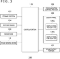
- FIG. 3 depicts a functional block of the HMD 100.
- a control portion 120 is a main processor that processes and outputs various types of data such as the image data, the sound data, and the sensor data and commands.
- a storage portion 122 temporarily stores the data, the commands, and the like processed by the control portion 120.
- the posture sensor 124 acquires the sensor data regarding the movement of the HMD 100.
- the posture sensor 124 includes at least a three-axis acceleration sensor and a three-axis gyro sensor.
- a communication control portion 128 transmits data output from the control portion 120, to the external information processing device 10 through a network adapter or an antenna by wired or wireless communication. In addition, the communication control portion 128 receives data from the information processing device 10, and outputs it to the control portion 120.
- control portion 120 When the control portion 120 receives the game image data or the game sound data from the information processing device 10, the control portion 120 supplies the game image data to the display panel 130 and makes the display panel 130 display the image or supplies the game sound data to a sound output portion 132 and makes the sound output portion 132 output the sound.
- the display panel 130 includes the display panel for the left eye 130a and the display panel for the right eye 130b, and a pair of parallax images are displayed on the display panels.
- the control portion 120 causes the sensor data from the posture sensor 124, the sound data from a microphone 126, and captured image data from the image sensing devices 14 to be transmitted from the communication control portion 128 to the information processing device 10.
- FIG. 4 depicts the external shape of the input device 16.
- FIG. 4(a) depicts the front shape of the input device 16
- FIG. 4(b) depicts the back shape of the input device 16.
- the input device 16 includes a case body 20, a plurality of operation members 22a, 22b, 22c, and 22d (hereinafter referred to as the "operation members 22" when they are not particularly distinguished) operated by the user, and a plurality of markers 30a to 30t (hereinafter referred to as the "marker 30" or “markers 30" when they are not particularly distinguished) for emitting light to the outside of the case body 20.
- the operation members 22 are arranged on the head of the case body 20, and include an analog stick for performing a tilt operation, a press button, a trigger button for inputting a pulled amount, and the like.
- An indicator 32 indicating the state of the input device 16 is arranged on the head of the case body 20.
- the indicator 32 may include an LED device that displays the charged state of the battery of the input device 16.
- the case body 20 includes a grasping portion 21 and a curved portion 23 that couples a case body head portion and a case body bottom portion, and the user passes fingers ranging from the index finger to the little finger between the grasping portion 21 and the curved portion 23 so as to grasp the grasping portion 21.
- the user In a state where the user grasps the grasping portion 21, the user operates the operation members 22a, 22b, and 22c with the thumb and operates the operation member 22d with the index finger.
- the markers 30h, 30i, and 30j are provided on the grasping portion 21, they are arranged in such positions that they are not hidden by the hand even in a state where the user grasps the grasping portion 21. At least one or more markers 30 are provided on the grasping portion 21, thus enhancing the accuracy of tracking.
- the marker 30 is a light emitting portion that emits light to the outside of the case body 20, and includes a resin portion that diffusely emits light from a light source such as an LED element to the outside on the surface of the case body 20.
- the marker 30 is imaged with the image sensing devices 14 so as to be used for estimation processing of position information and posture information regarding the input device 16.
- the image sensing devices 14 image the input device 16 at predetermined intervals (for example, 60 frames/second)
- the marker 30 emits light in synchronization with periodical imaging timing of the image sensing devices 14 and is unlit in the non-exposure period of the image sensing devices 14 so as to reduce unnecessary power consumption.
- the image sensing devices 14 and the input device 16 are operated based on respective clocks, and in the embodiment, synchronous processing on the exposure period of the image sensing devices 14 and a period during which the marker 30 is lit is performed as follows.
- FIG. 5 depicts an example of a light emission pattern for the synchronous processing that is used to identify timing of imaging by the image sensing devices 14.
- a length in a horizontal direction represents an imaging interval (16.7 msec) corresponding to one frame, and lighting control on the marker 30 is performed in units of time grids obtained by dividing the imaging interval.
- the imaging interval is divided into 32 parts, and one time grid is 521 ⁇ sec.
- the time grid that is colored indicates a lighting period at a first brightness
- the time grid that is not colored indicates a lighting period at a second brightness. Note that, the first brightness is different from the second brightness, and the first brightness may be higher than the second brightness.
- the marker 30 is imaged when light is emitted at the first brightness
- a high-brightness marker image is included in the captured image
- a low-brightness marker image is included in the captured image.
- the light emission pattern is determined such that when the marker 30 is continuously imaged at the imaging intervals corresponding to one frame so as to obtain six captured images, the order in which light is emitted at the first brightness and light is emitted at the second brightness differs depending on the time grid.
- one or more markers 30 imaged with the image sensing devices 14 are subjected to lighting control using the light emission pattern illustrated in FIG. 5 . It is assumed that the marker 30 is imaged under such lighting control that, after the start of the synchronous processing, the marker 30 is lit at the "first brightness” for the first captured image (Frame 0), the marker 30 is lit at the "second brightness” for the second captured image (Frame 1), the marker 30 is lit at the "first brightness” for the third captured image (Frame 2), the marker 30 is lit at the "second brightness” for the fourth captured image (Frame 3), the marker 30 is lit at the "second brightness” for the fifth captured image (Frame 4), and the marker 30 is lit at the "first brightness” for the sixth captured image (Frame 5).
- a time grid corresponding to a combination of the first brightness and the second brightness in the six continuous captured images is the time grid of grid number 14.
- the input device 16 periodically lights the marker 30 with timing of grid number 14, and can thereby perform such control that the period during which the marker 30 is lit is synchronized with the exposure period of the image sensing devices 14 to prevent the marker 30 from being lit in the non-exposure period of the image sensing devices 14.
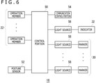
- FIG. 6 depicts a functional block of the input device 16.
- a control portion 50 receives operation information that is input to the operation members 22, and also receives sensor data acquired with a posture sensor 52.
- the posture sensor 52 acquires the sensor data regarding the movement of the input device 16, and includes at least a three-axis acceleration sensor and a three-axis gyro sensor.
- the control portion 50 supplies, to a communication control portion 54, the operation information and the sensor data that are received.
- the communication control portion 54 transmits the operation information and the sensor data output from the control portion 50, to the information processing device 10 through a network adapter or an antenna by wired or wireless communication. Further, the communication control portion 54 acquires the light emission pattern for the synchronous processing and/or an instruction to emit light, from the information processing device 10.
- the input device 16 includes a light source 56 for lighting the indicator 32 and light sources 58 for lighting the markers 30.
- Each of the light source 56 and the light sources 58 may be an LED element.
- the marker 30 includes the resin portion that diffusely emits light to the outside on the surface of the case body 20, and the resin portion of the marker 30 lit by the light source 58 may be a resin for sealing an LED element.
- the marker 30 and the light source 58 may have a form of one LED device.
- the indicator 32 assumes the role of notifying the user of the charged state of the battery in the input device 16.
- the light source 56 can emit light of a plurality of colors, and the indicator 32 may represent the charged state by the lighting color. For example, when the indicator 32 is lit in green, this indicates that the charged state is satisfactory, whereas, when the indicator 32 is lit in red, this indicates that the remaining amount in the battery is small. The user can recognize the charged state of the battery from the lighting color of the indicator 32.
- FIG. 7 depicts an example of part of an image obtained by imaging the input device 16.
- the captured image includes the images of the markers 30 that emit light.
- the communication control portion 128 transmits the image data obtained by imaging by the image sensing devices 14 to the information processing device 10, and the information processing device 10 extracts the images of the markers 30 from the image data.
- the information processing device 10 can distinguish the case where the marker 30 emits light at the first brightness and the case where the marker 30 emits light at the second brightness.
- the synchronous processing may be performed while the game is being played. Since the image sensing devices 14 cannot image the image of the marker 30 when synchronization is lost, it is necessary to immediately perform the synchronous processing in a case where the synchronization is lost.
- the control portion 50 makes one or more light sources 58 emit light with the light emission pattern for the synchronous processing (see FIG. 5 ) provided from the information processing device 10.
- the period during which the marker 30 is lit at the first brightness and the period during which the marker 30 is lit at the second brightness are determined in a plurality of frame periods.
- the information processing device 10 identifies a pattern of changes in the brightness value of the marker 30 included in a plurality of continuous captured images, so as to identify a time grid number included in the exposure period of the image sensing devices 14.
- the exposure period may be set to a length approximately twice the time grid.
- FIG. 8 depicts the period during which the marker 30 is lit that is set within the exposure period of the image sensing devices 14.
- the information processing device 10 identifies the time grid number
- the information processing device 10 generates an instruction to emit light at the timing of the time grid number and transmits it to the input device 16.
- the control portion 50 based on the instruction to emit light, the control portion 50 periodically makes all the markers 30 emit light in the time position of grid number 14. After the establishment of the synchronization, the control portion 50 turns on the light source for only a length of one time grid (521 microseconds) in one frame period, and turns off the light source in a period other than the one time grid, with the result that it is possible to reduce wasted power consumption.
- the indicator 32 uses the lighting color to notify the user of the charged state of the battery, since the indicator 32 is not the marker 30, it is undesirable that the image of the indicator 32 is included in the captured image.
- the control portion 50 lights the indicator 32 in a period during which the markers 30 are unlit.
- FIG. 9 illustrates a relation between a period during which the markers are lit and a period during which the indicator is lit.
- the control portion 50 sets, within the exposure period of the image sensing devices 14, the period during which the markers 30 are to be lit.
- the control portion 50 controls the light emission of the light source 56 such that the period during the indicator 32 is lit is prevented from overlapping the period during which the markers 30 are lit.
- the control portion 50 makes the light source 56 emit light in the period during which the markers 30 are unlit so as to light the indicator 32. In other words, the control portion 50 does not light the indicator 32 in the period during which the markers 30 are lit.
- the control portion 50 does not light the indicator 32 in the exposure period during which the image sensing devices 14 image the input device 16. In this way, the image sensing devices 14 do not image the indicator 32 that is lit. Note that, since the image sensing devices 14 and the input device 16 are operated based on respective clocks, the accurate timing at which the image sensing devices 14 start the exposure remains unclear for the control portion 50. However, since the control portion 50 is in possession of the length of the light exposure period, the control portion 50 can establish an additional predetermined time period around the period during which the markers 30 are lit, and thereby set an indicator lighting disabled period that certainly includes the exposure period.
- the control portion 50 may determine the period during which the indicator 32 is to be lit to fall within a period other than the indicator lighting disabled period.
- the predetermined time period may be determined with reference to the time grids, and the control portion 50 may establish an additional time period corresponding to two or more time grids around the period during which the markers 30 are lit so as to set the indicator lighting disabled period, and may thereby determine the period during which the indicator 32 is to be lit.
- the communication control portion 128 transmits the image data obtained by imaging by the image sensing devices 14 to the information processing device 10, the information processing device 10 extracts the images of the markers 30 from the image data. Since the three-dimensional shape of the input device 16 and the position coordinates of the markers 30 arranged on the surface thereof are known, the information processing device 10 solves a Perspective n-Point (PnP) problem from the distribution of the images of the markers 30 within the captured image so as to estimate the position and posture of the input device 16 with respect to the image sensing devices 14.
- PnP Perspective n-Point
- the device to be tracked does not necessarily need to include the operation members 22.
- the image sensing devices 14 are attached to the HMD 100, the image sensing devices 14 may be attached to positions other than the HMD 100 as long as the image sensing devices 14 can image marker images.
- the present invention can be used for a device including a plurality of markers.
Landscapes
- Engineering & Computer Science (AREA)
- Multimedia (AREA)
- Human Computer Interaction (AREA)
- General Engineering & Computer Science (AREA)
- Theoretical Computer Science (AREA)
- Physics & Mathematics (AREA)
- General Physics & Mathematics (AREA)
- Optics & Photonics (AREA)
- Position Input By Displaying (AREA)
- User Interface Of Digital Computer (AREA)
- Length Measuring Devices By Optical Means (AREA)
Abstract
Description
- The present invention relates to a device including a plurality of markers.
-
PTL 1 discloses a game device that acquires a frame image obtained by imaging a space in front of the game device, that estimates, from the position of a light emitting diode (LED) image of a game controller in the frame image, position information and posture information regarding the game controller in a real space, and that reflects the estimated position information and/or posture information on the processing of a game application. - [PTL 1]
Japanese Patent Laid-open No. 2007-296248 - A head-mounted display (HMD) is fitted to the head of a user to provide the user with a virtual reality (VR) video space. The user who wears the HMD operates operation buttons in an input device and can thereby produce various inputs to the video space.
- In recent years, techniques for tracking the position and posture of a device to reflect information obtained, on a three-dimensional (3D) model in a VR space, have widely been used. The movement of a player character or a game object in a game space is synchronized with changes in the position and posture of a device to be tracked, and thus an intuitive operation by a user is realized. A plurality of markers that are lit are used for the tracking of the device, an image obtained by imaging the plurality of markers is analyzed, and the positions of marker images within the image are thus identified, with the result that the position and posture of the device in a real space are estimated.
- In order to estimate the position and posture of the device with a high degree of accuracy, it is necessary to accurately identify the positions of the marker images within the image obtained by imaging the device. When an image other than the markers is included in a captured image, this may adversely affect the accuracy of estimation of the position and posture of the device, and thus such an image is preferably prevented from being included in the captured image.
- Hence, an object of the present invention is to prevent a lit portion other than markers in a device including a plurality of markers from being included in a captured image. Note that, while the device may be an input device that includes operation buttons, the device may be a device that is simply a target to be tracked without including operation members.
- In order to solve the problem described above, a device according to an aspect of the present invention includes a case body and a plurality of markers configured to emit light to the outside of the case body. The device includes a control portion for lighting the plurality of markers at predetermined intervals, and the control portion lights an indicator indicating the state of the device, in a period during which the plurality of markers are unlit.
-
- [
FIG. 1 ]
FIG. 1 is a diagram depicting an example of the configuration of an information processing system in an embodiment. - [
FIG. 2 ]
FIG. 2 is a diagram depicting an example of the external shape of an HMD. - [
FIG. 3 ]
FIG. 3 is a diagram depicting a functional block of the HMD. - [
FIG. 4 ]
FIG. 4 depicts diagrams illustrating the external shape of an input device. - [
FIG. 5 ]
FIG. 5 is a diagram illustrating an example of a light emission pattern for synchronous processing that is used to identify timing of imaging by image sensing devices. - [
FIG. 6 ]
FIG. 6 is a diagram illustrating a functional block of the input device. - [
FIG. 7 ]
FIG. 7 is a diagram depicting an example of part of an image obtained by imaging the input device. - [
FIG. 8 ]
FIG. 8 is a diagram illustrating a period during which a marker is lit that is set within the exposure period of the image sensing devices. - [
FIG. 9 ]
FIG. 9 is a diagram illustrating a relation between a period during which markers are lit and a period during which an indicator is lit. -
FIG. 1 depicts an example of the configuration of aninformation processing system 1 in an embodiment. Theinformation processing system 1 includes aninformation processing device 10, arecording device 11, an HMD 100, aninput device 16 that is operated with fingers of a user, and anoutput device 15 that outputs images and sounds. Theoutput device 15 may be a television set. Theinformation processing device 10 is connected through an access point (AP) 17 to anexternal network 2 such as the Internet. The AP 17 has the functions of a wireless access point and a router, and theinformation processing device 10 may be connected to the AP 17 with a cable or may be connected thereto with a known wireless communication protocol. - The
recording device 11 records system software and applications such as game software. Theinformation processing device 10 may download the game software to therecording device 11 from a content server through thenetwork 2. Theinformation processing device 10 executes the game software and supplies image data and sound data of the game to the HMD 100. Theinformation processing device 10 and the HMD 100 may be connected to each other with a known wireless communication protocol or may be connected to each other with a cable. - The HMD 100 is a display device that is fitted to the head by the user, to display images on display panels located in front of the eyes. The HMD 100 individually displays an image for the left eye on a display panel for the left eye and an image for the right eye on a display panel for the right eye. These images form parallax images seen from left and right eyepoints to realize a stereoscopic view. In order for the user to look at the display panels through optical lenses, the
information processing device 10 supplies, to theHMD 100, parallax image data obtained by correcting optical distortion caused by the lenses. - Although the
output device 15 is not needed for the user who wears the HMD 100, preparing theoutput device 15 enables another user to see the display image of theoutput device 15. While theinformation processing device 10 may display, on theoutput device 15, the same image as the image seen by the user who is wearing the HMD 100, another image may be displayed. For example, when the user who is wearing the HMD 100 plays a game together with another user, a game image from the eyepoint of a character of the other user may be displayed from theoutput device 15. - The
information processing device 10 and theinput device 16 may be connected to each other with a known wireless communication protocol or may be connected to each other with a cable. Theinput device 16 includes a plurality of operation members such as operation buttons, and the user operates the operation members with the fingers while grasping theinput device 16. When theinformation processing device 10 executes a game, theinput device 16 is used as a game controller. Theinput device 16 is provided with a posture sensor including a three-axis acceleration sensor and a three-axis gyro sensor, and transmits sensor data to theinformation processing device 10 at a predetermined cycle (for example, 1600 Hz). - The game of the embodiment handles not only the operation information of the operation members in the
input device 16 but also the operation information of the position, the posture, the movement, and the like of theinput device 16, and reflects the operation information on the movement of the player character within a virtual three-dimensional space. For example, the operation information of the operation members may be used as information for moving the player character, and the operation information of the position, the posture, the movement and the like of theinput device 16 may be used as information for moving an arm of the player character. In a battle scene within the game, the movement of theinput device 16 is reflected on the movement of the player character holding a weapon, and thus an intuitive operation by the user is realized, with the result that the immersion of the user in the game is enhanced. - In order to track the position and posture of the
input device 16, a plurality of markers (light emitting portions) that can be imaged withimage sensing devices 14 mounted on the HMD 100 are provided on theinput device 16. Theinformation processing device 10 analyzes an image obtained by imaging theinput device 16, to estimate the position information and posture information of theinput device 16 in a real space, and provides the estimated position information and posture information to the game. - On the
HMD 100, a plurality ofimage sensing devices 14 are mounted. The plurality ofimage sensing devices 14 are attached to different positions of the front surface of theHMD 100 with different postures such that the overall imaging range obtained by adding up the imaging ranges of theimage sensing devices 14 includes the entire field of view of the user. Theimage sensing device 14 is preferably an image sensor that can acquire the images of the plurality of markers in theinput device 16. For example, when the marker emits visible light, theimage sensing device 14 includes a visible light sensor, such as a charge coupled device (CCD) sensor or a complementary metal oxide semiconductor (CMOS) sensor, that is used in a general digital video camera. When the marker emits invisible light, theimage sensing device 14 includes an invisible light sensor. The plurality ofimage sensing devices 14 image a space in front of the user at a synchronized timing and predetermined intervals (for example, 60 frames/second), and transmit image data obtained by imaging theinput device 16 to theinformation processing device 10. - The
information processing device 10 identifies the positions of a plurality of marker images of theinput device 16 included in a captured image. Note that, while the oneinput device 16 may be imaged with a plurality ofimage sensing devices 14 at the same timing, since the attachment positions and attachment postures of theimage sensing devices 14 are known, theinformation processing device 10 combines a plurality of captured images to identify the positions of the marker images. - The three-dimensional shape of the
input device 16 and the position coordinates of the plurality of markers arranged on the surface thereof are known, and thus, theinformation processing device 10 estimates the position coordinates and the posture of theinput device 16, based on the distribution of the marker images within the captured image. The position coordinates of theinput device 16 may be position coordinates in a three-dimensional space with a reference position being an origin, and the reference position may be position coordinates (longitude and latitude) set before the start of the game. - Note that the
information processing device 10 can also estimate the position coordinates and the posture of theinput device 16 by using the sensor data detected with the posture sensor in theinput device 16. Hence, theinformation processing device 10 of the embodiment uses the result of the estimation based on the captured image obtained with theimage sensing devices 14 and the result of the estimation based on the sensor data, so as to perform tracking processing on theinput device 16 with a high degree of accuracy. -
FIG. 2 depicts an example of the external shape of theHMD 100. TheHMD 100 includes anoutput mechanism portion 102 and afitting mechanism portion 104. Thefitting mechanism portion 104 includes afitting band 106 that is put on by the user to be worn around the head so as to fix theHMD 100 to the head. Thefitting band 106 has a material or a structure in which the length thereof can be adjusted according to the head circumference of the user. - The
output mechanism portion 102 includes ahousing 108 having a shape that covers the left and right eyes in a state where the user is wearing theHMD 100, and also includes, therewithin, the display panels directly opposite the eyes when theHMD 100 is worn. The display panel may be a liquid crystal panel, an organic electroluminescence (EL) panel, or the like. Within thehousing 108, a pair of left and right optical lenses that are located between the display panels and the eyes of the user to enlarge the viewing angle of the user are further included. TheHMD 100 may further include speakers and earphones in positions corresponding to the ears of the user or may be configured such that external headphones are connected thereto. - A plurality of
image sensing devices housing 108. With reference to the direction of the line of sight of the user, theimage sensing device 14a is attached to an upper right corner of the outer surface on the forward side such that a camera optical axis is directed diagonally upward to the right, theimage sensing device 14b is attached to an upper left corner of the outer surface on the forward side such that the camera optical axis is directed diagonally upward to the left, theimage sensing device 14c is attached to a lower right corner of the outer surface on the forward side such that the camera optical axis is directed diagonally downward to the right, and theimage sensing device 14d is attached to a lower left corner of the outer surface on the forward side such that the camera optical axis is directed diagonally downward to the left. A plurality ofimage sensing devices 14 are installed in this way, and thus, the overall imaging range obtained by adding up the imaging ranges of theimage sensing devices 14 includes the entire field of view of the user. The field of view of the user described above may be the field of view of the user in a virtual three-dimensional space. - The
HMD 100 transmits, to theinformation processing device 10, the sensor data detected with the posture sensor and the image data obtained by imaging by theimage sensing devices 14, and receives game image data and game sound data generated in theinformation processing device 10. -
FIG. 3 depicts a functional block of theHMD 100. Acontrol portion 120 is a main processor that processes and outputs various types of data such as the image data, the sound data, and the sensor data and commands. Astorage portion 122 temporarily stores the data, the commands, and the like processed by thecontrol portion 120. Theposture sensor 124 acquires the sensor data regarding the movement of theHMD 100. Theposture sensor 124 includes at least a three-axis acceleration sensor and a three-axis gyro sensor. - A
communication control portion 128 transmits data output from thecontrol portion 120, to the externalinformation processing device 10 through a network adapter or an antenna by wired or wireless communication. In addition, thecommunication control portion 128 receives data from theinformation processing device 10, and outputs it to thecontrol portion 120. - When the
control portion 120 receives the game image data or the game sound data from theinformation processing device 10, thecontrol portion 120 supplies the game image data to thedisplay panel 130 and makes thedisplay panel 130 display the image or supplies the game sound data to asound output portion 132 and makes thesound output portion 132 output the sound. Thedisplay panel 130 includes the display panel for theleft eye 130a and the display panel for theright eye 130b, and a pair of parallax images are displayed on the display panels. Further, thecontrol portion 120 causes the sensor data from theposture sensor 124, the sound data from amicrophone 126, and captured image data from theimage sensing devices 14 to be transmitted from thecommunication control portion 128 to theinformation processing device 10. -
FIG. 4 depicts the external shape of theinput device 16.FIG. 4(a) depicts the front shape of theinput device 16, andFIG. 4(b) depicts the back shape of theinput device 16. Theinput device 16 includes acase body 20, a plurality ofoperation members operation members 22" when they are not particularly distinguished) operated by the user, and a plurality ofmarkers 30a to 30t (hereinafter referred to as the "marker 30" or "markers 30" when they are not particularly distinguished) for emitting light to the outside of thecase body 20. Theoperation members 22 are arranged on the head of thecase body 20, and include an analog stick for performing a tilt operation, a press button, a trigger button for inputting a pulled amount, and the like. Anindicator 32 indicating the state of theinput device 16 is arranged on the head of thecase body 20. Theindicator 32 may include an LED device that displays the charged state of the battery of theinput device 16. - The
case body 20 includes a graspingportion 21 and acurved portion 23 that couples a case body head portion and a case body bottom portion, and the user passes fingers ranging from the index finger to the little finger between the graspingportion 21 and thecurved portion 23 so as to grasp the graspingportion 21. In a state where the user grasps the graspingportion 21, the user operates theoperation members operation member 22d with the index finger. Although themarkers portion 21, they are arranged in such positions that they are not hidden by the hand even in a state where the user grasps the graspingportion 21. At least one ormore markers 30 are provided on the graspingportion 21, thus enhancing the accuracy of tracking. - The
marker 30 is a light emitting portion that emits light to the outside of thecase body 20, and includes a resin portion that diffusely emits light from a light source such as an LED element to the outside on the surface of thecase body 20. Themarker 30 is imaged with theimage sensing devices 14 so as to be used for estimation processing of position information and posture information regarding theinput device 16. Preferably, since theimage sensing devices 14 image theinput device 16 at predetermined intervals (for example, 60 frames/second), themarker 30 emits light in synchronization with periodical imaging timing of theimage sensing devices 14 and is unlit in the non-exposure period of theimage sensing devices 14 so as to reduce unnecessary power consumption. Theimage sensing devices 14 and theinput device 16 are operated based on respective clocks, and in the embodiment, synchronous processing on the exposure period of theimage sensing devices 14 and a period during which themarker 30 is lit is performed as follows. -
FIG. 5 depicts an example of a light emission pattern for the synchronous processing that is used to identify timing of imaging by theimage sensing devices 14. A length in a horizontal direction represents an imaging interval (16.7 msec) corresponding to one frame, and lighting control on themarker 30 is performed in units of time grids obtained by dividing the imaging interval. In this example, the imaging interval is divided into 32 parts, and one time grid is 521 µsec. InFIG. 5 , the time grid that is colored indicates a lighting period at a first brightness, and the time grid that is not colored indicates a lighting period at a second brightness. Note that, the first brightness is different from the second brightness, and the first brightness may be higher than the second brightness. In a case where themarker 30 is imaged when light is emitted at the first brightness, a high-brightness marker image is included in the captured image, whereas, in a case where themarker 30 is imaged when light is emitted at the second brightness, a low-brightness marker image is included in the captured image. The light emission pattern is determined such that when themarker 30 is continuously imaged at the imaging intervals corresponding to one frame so as to obtain six captured images, the order in which light is emitted at the first brightness and light is emitted at the second brightness differs depending on the time grid. - In the synchronous processing, one or
more markers 30 imaged with theimage sensing devices 14 are subjected to lighting control using the light emission pattern illustrated inFIG. 5 . It is assumed that themarker 30 is imaged under such lighting control that, after the start of the synchronous processing, themarker 30 is lit at the "first brightness" for the first captured image (Frame 0), themarker 30 is lit at the "second brightness" for the second captured image (Frame 1), themarker 30 is lit at the "first brightness" for the third captured image (Frame 2), themarker 30 is lit at the "second brightness" for the fourth captured image (Frame 3), themarker 30 is lit at the "second brightness" for the fifth captured image (Frame 4), and themarker 30 is lit at the "first brightness" for the sixth captured image (Frame 5). A time grid corresponding to a combination of the first brightness and the second brightness in the six continuous captured images is the time grid ofgrid number 14. Hence, thereafter, theinput device 16 periodically lights themarker 30 with timing ofgrid number 14, and can thereby perform such control that the period during which themarker 30 is lit is synchronized with the exposure period of theimage sensing devices 14 to prevent themarker 30 from being lit in the non-exposure period of theimage sensing devices 14. -
FIG. 6 depicts a functional block of theinput device 16. Acontrol portion 50 receives operation information that is input to theoperation members 22, and also receives sensor data acquired with aposture sensor 52. Theposture sensor 52 acquires the sensor data regarding the movement of theinput device 16, and includes at least a three-axis acceleration sensor and a three-axis gyro sensor. Thecontrol portion 50 supplies, to acommunication control portion 54, the operation information and the sensor data that are received. Thecommunication control portion 54 transmits the operation information and the sensor data output from thecontrol portion 50, to theinformation processing device 10 through a network adapter or an antenna by wired or wireless communication. Further, thecommunication control portion 54 acquires the light emission pattern for the synchronous processing and/or an instruction to emit light, from theinformation processing device 10. - The
input device 16 includes alight source 56 for lighting theindicator 32 andlight sources 58 for lighting themarkers 30. Each of thelight source 56 and thelight sources 58 may be an LED element. Themarker 30 includes the resin portion that diffusely emits light to the outside on the surface of thecase body 20, and the resin portion of themarker 30 lit by thelight source 58 may be a resin for sealing an LED element. Here, themarker 30 and thelight source 58 may have a form of one LED device. - The
indicator 32 assumes the role of notifying the user of the charged state of the battery in theinput device 16. Thelight source 56 can emit light of a plurality of colors, and theindicator 32 may represent the charged state by the lighting color. For example, when theindicator 32 is lit in green, this indicates that the charged state is satisfactory, whereas, when theindicator 32 is lit in red, this indicates that the remaining amount in the battery is small. The user can recognize the charged state of the battery from the lighting color of theindicator 32. -
FIG. 7 depicts an example of part of an image obtained by imaging theinput device 16. As illustrated in the figure, the captured image includes the images of themarkers 30 that emit light. In theHMD 100, thecommunication control portion 128 transmits the image data obtained by imaging by theimage sensing devices 14 to theinformation processing device 10, and theinformation processing device 10 extracts the images of themarkers 30 from the image data. In the synchronous processing, theinformation processing device 10 can distinguish the case where themarker 30 emits light at the first brightness and the case where themarker 30 emits light at the second brightness. - While the synchronous processing on the exposure period of the
image sensing devices 14 and the period during which themarker 30 is lit is performed before the start of the game, the synchronous processing may be performed while the game is being played. Since theimage sensing devices 14 cannot image the image of themarker 30 when synchronization is lost, it is necessary to immediately perform the synchronous processing in a case where the synchronization is lost. - In the synchronous processing, the
control portion 50 makes one or morelight sources 58 emit light with the light emission pattern for the synchronous processing (seeFIG. 5 ) provided from theinformation processing device 10. As depicted inFIG. 5 , in the light emission pattern, the period during which themarker 30 is lit at the first brightness and the period during which themarker 30 is lit at the second brightness are determined in a plurality of frame periods. Theinformation processing device 10 identifies a pattern of changes in the brightness value of themarker 30 included in a plurality of continuous captured images, so as to identify a time grid number included in the exposure period of theimage sensing devices 14. For example, the exposure period may be set to a length approximately twice the time grid. -
FIG. 8 depicts the period during which themarker 30 is lit that is set within the exposure period of theimage sensing devices 14. When theinformation processing device 10 identifies the time grid number, theinformation processing device 10 generates an instruction to emit light at the timing of the time grid number and transmits it to theinput device 16. In theinput device 16, based on the instruction to emit light, thecontrol portion 50 periodically makes all themarkers 30 emit light in the time position ofgrid number 14. After the establishment of the synchronization, thecontrol portion 50 turns on the light source for only a length of one time grid (521 microseconds) in one frame period, and turns off the light source in a period other than the one time grid, with the result that it is possible to reduce wasted power consumption. - Although, in the embodiment, the
indicator 32 uses the lighting color to notify the user of the charged state of the battery, since theindicator 32 is not themarker 30, it is undesirable that the image of theindicator 32 is included in the captured image. Hence, after the establishment of the synchronization, while lighting a plurality ofmarkers 30 at predetermined intervals, thecontrol portion 50 lights theindicator 32 in a period during which themarkers 30 are unlit. -
FIG. 9 illustrates a relation between a period during which the markers are lit and a period during which the indicator is lit. As also illustrated inFIG. 8 , thecontrol portion 50 sets, within the exposure period of theimage sensing devices 14, the period during which themarkers 30 are to be lit. On the other hand, thecontrol portion 50 controls the light emission of thelight source 56 such that the period during theindicator 32 is lit is prevented from overlapping the period during which themarkers 30 are lit. Specifically, thecontrol portion 50 makes thelight source 56 emit light in the period during which themarkers 30 are unlit so as to light theindicator 32. In other words, thecontrol portion 50 does not light theindicator 32 in the period during which themarkers 30 are lit. - With reference to the exposure period of the
image sensing devices 14, thecontrol portion 50 does not light theindicator 32 in the exposure period during which theimage sensing devices 14 image theinput device 16. In this way, theimage sensing devices 14 do not image theindicator 32 that is lit. Note that, since theimage sensing devices 14 and theinput device 16 are operated based on respective clocks, the accurate timing at which theimage sensing devices 14 start the exposure remains unclear for thecontrol portion 50. However, since thecontrol portion 50 is in possession of the length of the light exposure period, thecontrol portion 50 can establish an additional predetermined time period around the period during which themarkers 30 are lit, and thereby set an indicator lighting disabled period that certainly includes the exposure period. Thecontrol portion 50 may determine the period during which theindicator 32 is to be lit to fall within a period other than the indicator lighting disabled period. The predetermined time period may be determined with reference to the time grids, and thecontrol portion 50 may establish an additional time period corresponding to two or more time grids around the period during which themarkers 30 are lit so as to set the indicator lighting disabled period, and may thereby determine the period during which theindicator 32 is to be lit. - When, in the
HMD 100, thecommunication control portion 128 transmits the image data obtained by imaging by theimage sensing devices 14 to theinformation processing device 10, theinformation processing device 10 extracts the images of themarkers 30 from the image data. Since the three-dimensional shape of theinput device 16 and the position coordinates of themarkers 30 arranged on the surface thereof are known, theinformation processing device 10 solves a Perspective n-Point (PnP) problem from the distribution of the images of themarkers 30 within the captured image so as to estimate the position and posture of theinput device 16 with respect to theimage sensing devices 14. - The present invention has been described above based on the embodiment. The embodiment described above is illustrative, and a person skilled in the art would understand that various variations of the constituent elements thereof and the combination of processing processes are possible and that the variations are also within the scope of the present invention.
- Although, in the embodiment, the arrangement of a plurality of
markers 30 in theinput device 16 including theoperation members 22 is described, the device to be tracked does not necessarily need to include theoperation members 22. In addition, although, in the embodiment, theimage sensing devices 14 are attached to theHMD 100, theimage sensing devices 14 may be attached to positions other than theHMD 100 as long as theimage sensing devices 14 can image marker images. - The present invention can be used for a device including a plurality of markers.
-
- 1:
- Information processing system
- 10:
- Information processing device
- 14:
- Image sensing device
- 16:
- Input device
- 30:
- Marker
- 32:
- Indicator
- 50:
- Control portion
- 56, 58:
- Light source
Claims (5)
- A device comprising:a case body; anda plurality of markers configured to emit light to an outside of the case body,wherein the device includes a control portion configured to light the plurality of markers at predetermined intervals, and the control portion lights an indicator that indicates a state of the device, in a period during which the plurality of markers are unlit.
- The device according to claim 1,
wherein the control portion does not light the indicator in a period during which the plurality of markers are lit. - The device according to claim 1 or 2,
wherein the control portion does not light the indicator in an exposure period during which an image sensing device images the device. - The device according to any one of claims 1 to 3,
wherein the device is an input device including an operation member operated by a user. - The device according to any one of claims 1 to 4,
wherein the device is imaged with an image sensing device attached to a head-mounted display.
Applications Claiming Priority (2)
| Application Number | Priority Date | Filing Date | Title |
|---|---|---|---|
| JP2019075855A JP7283958B2 (en) | 2019-04-11 | 2019-04-11 | Device with multiple markers |
| PCT/JP2020/013746 WO2020209088A1 (en) | 2019-04-11 | 2020-03-26 | Device having plural markers |
Publications (3)
| Publication Number | Publication Date |
|---|---|
| EP3954443A1 true EP3954443A1 (en) | 2022-02-16 |
| EP3954443A4 EP3954443A4 (en) | 2023-01-04 |
| EP3954443B1 EP3954443B1 (en) | 2025-06-04 |
Family
ID=72751074
Family Applications (1)
| Application Number | Title | Priority Date | Filing Date |
|---|---|---|---|
| EP20787365.4A Active EP3954443B1 (en) | 2019-04-11 | 2020-03-26 | Device having plural markers |
Country Status (5)
| Country | Link |
|---|---|
| US (1) | US12083415B2 (en) |
| EP (1) | EP3954443B1 (en) |
| JP (1) | JP7283958B2 (en) |
| CN (1) | CN113660986A (en) |
| WO (1) | WO2020209088A1 (en) |
Cited By (2)
| Publication number | Priority date | Publication date | Assignee | Title |
|---|---|---|---|---|
| EP3890302A4 (en) * | 2018-11-30 | 2022-08-31 | Sony Interactive Entertainment Inc. | INFORMATION PROCESSING APPARATUS, INFORMATION PROCESSING SYSTEM, POSITION/ATTITUDE ACQUISITION DEVICE, AND DEVICE INFORMATION ACQUISITION METHOD |
| WO2024112911A1 (en) * | 2022-11-23 | 2024-05-30 | Meta Platforms Technologies, Llc | Arrangements of illumination sources within and outside of a digit-occluded region of a top cover of a handheld controller to assist with positional tracking of the controller by an artificial-reality system, and systems and methods of use thereof |
Families Citing this family (3)
| Publication number | Priority date | Publication date | Assignee | Title |
|---|---|---|---|---|
| JP7237049B2 (en) | 2020-10-15 | 2023-03-10 | プライムプラネットエナジー&ソリューションズ株式会社 | Manufacturing method of resin porous body |
| JP1686895S (en) * | 2020-10-30 | 2021-05-31 | ||
| US20240169681A1 (en) * | 2022-11-23 | 2024-05-23 | Meta Platforms Technologies, Llc | Arrangements of illumination sources within and outside of a digit-occluded region of a top cover of a handheld controller to assist with positional tracking of the controller by an artificial-reality system, and systems and methods of use thereof |
Family Cites Families (30)
| Publication number | Priority date | Publication date | Assignee | Title |
|---|---|---|---|---|
| JPS5714108U (en) | 1980-06-28 | 1982-01-25 | ||
| JP2005135425A (en) | 1998-02-16 | 2005-05-26 | Sony Computer Entertainment Inc | Protective case for portable electronic apparatus |
| JP5089060B2 (en) | 2006-03-14 | 2012-12-05 | 株式会社ソニー・コンピュータエンタテインメント | Entertainment system and game controller |
| JP4443531B2 (en) * | 2006-04-11 | 2010-03-31 | 株式会社ソニー・コンピュータエンタテインメント | Entertainment system and processing apparatus |
| JP5089078B2 (en) * | 2006-05-02 | 2012-12-05 | 株式会社ソニー・コンピュータエンタテインメント | Game device |
| JPWO2009093461A1 (en) | 2008-01-22 | 2011-05-26 | 新世代株式会社 | Imaging device, online game system, operation article, input method, image analysis device, image analysis method, and recording medium |
| EP2354896B1 (en) * | 2008-11-14 | 2016-12-21 | Sony Interactive Entertainment Inc. | Operating device and information processing apparatus |
| CN201319397Y (en) * | 2008-12-04 | 2009-09-30 | 罗忠廉 | Battery with electronic indicator |
| EP2573651A4 (en) | 2010-05-18 | 2016-04-20 | Fujitsu Ltd | POINTER INFORMATION PROCESSING DEVICE, POINTER INFORMATION PROCESSING PROGRAM, AND CONFERENCE SYSTEM |
| WO2013157053A1 (en) * | 2012-04-20 | 2013-10-24 | 任天堂株式会社 | Game system and game controller |
| US9779550B2 (en) | 2012-10-02 | 2017-10-03 | Sony Corporation | Augmented reality system |
| US20150170549A1 (en) | 2013-11-30 | 2015-06-18 | Kabushikigaisha Goto Kogaku Kenkyusho | Fixed-star projection cylinder |
| US9649558B2 (en) | 2014-03-14 | 2017-05-16 | Sony Interactive Entertainment Inc. | Gaming device with rotatably placed cameras |
| JP6355978B2 (en) * | 2014-06-09 | 2018-07-11 | 株式会社バンダイナムコエンターテインメント | Program and image generation apparatus |
| CN105417303A (en) * | 2014-09-11 | 2016-03-23 | 上海现代电梯制造有限公司 | Control method for door-opening button indicating light of lift car |
| US9746921B2 (en) * | 2014-12-31 | 2017-08-29 | Sony Interactive Entertainment Inc. | Signal generation and detector systems and methods for determining positions of fingers of a user |
| JP6477131B2 (en) | 2015-03-27 | 2019-03-06 | セイコーエプソン株式会社 | Interactive projector, interactive projection system, and control method of interactive projector |
| KR102458189B1 (en) | 2015-08-03 | 2022-10-25 | 삼성전자주식회사 | Health information generating device and electronic device for generating health information and method thereof |
| JP6650739B2 (en) * | 2015-11-30 | 2020-02-19 | 株式会社ソニー・インタラクティブエンタテインメント | Light emitting device adjustment apparatus and drive current adjustment method |
| JP6113897B1 (en) | 2016-08-22 | 2017-04-12 | 株式会社コロプラ | Method for providing virtual space, method for providing virtual experience, program, and recording medium |
| US10134192B2 (en) | 2016-10-17 | 2018-11-20 | Microsoft Technology Licensing, Llc | Generating and displaying a computer generated image on a future pose of a real world object |
| JP6917701B2 (en) | 2016-11-30 | 2021-08-11 | キヤノン株式会社 | Information processing device, control method and program of information processing device |
| EP3660636A4 (en) | 2017-07-27 | 2020-07-08 | Sony Corporation | INFORMATION PROCESSING DEVICE, INFORMATION PROCESSING PROCESS AND PROGRAM |
| US10540023B2 (en) | 2017-09-26 | 2020-01-21 | Yong Bum Kim | User interface devices for virtual reality system |
| JP6340464B1 (en) | 2017-09-27 | 2018-06-06 | 株式会社Cygames | Program, information processing method, information processing system, head-mounted display device, information processing device |
| US10529074B2 (en) | 2017-09-28 | 2020-01-07 | Samsung Electronics Co., Ltd. | Camera pose and plane estimation using active markers and a dynamic vision sensor |
| JP6853156B2 (en) | 2017-09-29 | 2021-03-31 | 株式会社日立製作所 | Posture estimation system, posture estimation device, and distance image camera |
| US11042226B2 (en) | 2018-04-02 | 2021-06-22 | Microsoft Technology Licensing, Llc | Constellation-based augmentation of mouse form-factor for virtual reality applications |
| WO2020030156A1 (en) | 2018-08-10 | 2020-02-13 | 广东虚拟现实科技有限公司 | Image processing method, terminal device, and computer readable medium |
| US11569826B2 (en) | 2020-02-16 | 2023-01-31 | Board Of Regents, The University Of Texas System | Time-domain incremental two-step capacitance-to-digital converter |
-
2019
- 2019-04-11 JP JP2019075855A patent/JP7283958B2/en active Active
-
2020
- 2020-03-26 CN CN202080026778.3A patent/CN113660986A/en active Pending
- 2020-03-26 US US17/440,858 patent/US12083415B2/en active Active
- 2020-03-26 EP EP20787365.4A patent/EP3954443B1/en active Active
- 2020-03-26 WO PCT/JP2020/013746 patent/WO2020209088A1/en not_active Ceased
Cited By (3)
| Publication number | Priority date | Publication date | Assignee | Title |
|---|---|---|---|---|
| EP3890302A4 (en) * | 2018-11-30 | 2022-08-31 | Sony Interactive Entertainment Inc. | INFORMATION PROCESSING APPARATUS, INFORMATION PROCESSING SYSTEM, POSITION/ATTITUDE ACQUISITION DEVICE, AND DEVICE INFORMATION ACQUISITION METHOD |
| US11831993B2 (en) | 2018-11-30 | 2023-11-28 | Sony Interactive Entertainment Inc. | Information processing apparatus, information processing system, device for position and posture acquisition, and device information acquisition method |
| WO2024112911A1 (en) * | 2022-11-23 | 2024-05-30 | Meta Platforms Technologies, Llc | Arrangements of illumination sources within and outside of a digit-occluded region of a top cover of a handheld controller to assist with positional tracking of the controller by an artificial-reality system, and systems and methods of use thereof |
Also Published As
| Publication number | Publication date |
|---|---|
| US20220143495A1 (en) | 2022-05-12 |
| US12083415B2 (en) | 2024-09-10 |
| JP2020173670A (en) | 2020-10-22 |
| EP3954443A4 (en) | 2023-01-04 |
| CN113660986A (en) | 2021-11-16 |
| EP3954443B1 (en) | 2025-06-04 |
| JP7283958B2 (en) | 2023-05-30 |
| WO2020209088A1 (en) | 2020-10-15 |
Similar Documents
| Publication | Publication Date | Title |
|---|---|---|
| EP3954443B1 (en) | Device having plural markers | |
| US11663737B2 (en) | Information processing apparatus and representative coordinate derivation method | |
| CN108292489B (en) | Information processing apparatus and image generating method | |
| US12544653B2 (en) | Device including plurality of markers | |
| US11232588B2 (en) | Information processing apparatus and device information derivation method | |
| US20200126280A1 (en) | Information processing system, information processing device, server device, image providing method and image generation method | |
| US12223679B2 (en) | Data processing | |
| US20210192799A1 (en) | Passthrough window object locator in an artificial reality system | |
| CN110882536A (en) | Chess and play game system based on AR equipment | |
| US11794095B2 (en) | Information processing apparatus and device information derivation method | |
| US12017137B2 (en) | Device including plurality of markers | |
| EP3729235B1 (en) | Data processing | |
| US20260069982A1 (en) | Information processing device and image generation method | |
| US20240257391A1 (en) | Information processing apparatus and device information derivation method | |
| US20250045998A1 (en) | System for illuminating the face | |
| JP2023027077A (en) | Display control device and display control method | |
| JPH1185385A (en) | Coordinate detection system and light emission body |
Legal Events
| Date | Code | Title | Description |
|---|---|---|---|
| STAA | Information on the status of an ep patent application or granted ep patent |
Free format text: STATUS: THE INTERNATIONAL PUBLICATION HAS BEEN MADE |
|
| PUAI | Public reference made under article 153(3) epc to a published international application that has entered the european phase |
Free format text: ORIGINAL CODE: 0009012 |
|
| STAA | Information on the status of an ep patent application or granted ep patent |
Free format text: STATUS: REQUEST FOR EXAMINATION WAS MADE |
|
| 17P | Request for examination filed |
Effective date: 20210930 |
|
| AK | Designated contracting states |
Kind code of ref document: A1 Designated state(s): AL AT BE BG CH CY CZ DE DK EE ES FI FR GB GR HR HU IE IS IT LI LT LU LV MC MK MT NL NO PL PT RO RS SE SI SK SM TR |
|
| DAV | Request for validation of the european patent (deleted) | ||
| DAX | Request for extension of the european patent (deleted) | ||
| REG | Reference to a national code |
Ref legal event code: R079 Ipc: A63F0013260000 Ref country code: DE Ref legal event code: R079 Ref document number: 602020052345 Country of ref document: DE Free format text: PREVIOUS MAIN CLASS: A63F0013213000 Ipc: A63F0013260000 |
|
| A4 | Supplementary search report drawn up and despatched |
Effective date: 20221206 |
|
| RIC1 | Information provided on ipc code assigned before grant |
Ipc: G06F 3/0346 20130101ALI20221130BHEP Ipc: G06F 3/01 20060101ALI20221130BHEP Ipc: A63F 13/5255 20140101ALI20221130BHEP Ipc: A63F 13/428 20140101ALI20221130BHEP Ipc: A63F 13/24 20140101ALI20221130BHEP Ipc: A63F 13/213 20140101ALI20221130BHEP Ipc: A63F 13/26 20140101AFI20221130BHEP |
|
| GRAP | Despatch of communication of intention to grant a patent |
Free format text: ORIGINAL CODE: EPIDOSNIGR1 |
|
| STAA | Information on the status of an ep patent application or granted ep patent |
Free format text: STATUS: GRANT OF PATENT IS INTENDED |
|
| INTG | Intention to grant announced |
Effective date: 20250120 |
|
| GRAS | Grant fee paid |
Free format text: ORIGINAL CODE: EPIDOSNIGR3 |
|
| GRAA | (expected) grant |
Free format text: ORIGINAL CODE: 0009210 |
|
| STAA | Information on the status of an ep patent application or granted ep patent |
Free format text: STATUS: THE PATENT HAS BEEN GRANTED |
|
| P01 | Opt-out of the competence of the unified patent court (upc) registered |
Free format text: CASE NUMBER: APP_18572/2025 Effective date: 20250416 |
|
| AK | Designated contracting states |
Kind code of ref document: B1 Designated state(s): AL AT BE BG CH CY CZ DE DK EE ES FI FR GB GR HR HU IE IS IT LI LT LU LV MC MK MT NL NO PL PT RO RS SE SI SK SM TR |
|
| REG | Reference to a national code |
Ref country code: GB Ref legal event code: FG4D |
|
| REG | Reference to a national code |
Ref country code: CH Ref legal event code: EP |
|
| REG | Reference to a national code |
Ref country code: DE Ref legal event code: R096 Ref document number: 602020052345 Country of ref document: DE |
|
| REG | Reference to a national code |
Ref country code: IE Ref legal event code: FG4D |
|
| REG | Reference to a national code |
Ref country code: NL Ref legal event code: MP Effective date: 20250604 |
|
| PG25 | Lapsed in a contracting state [announced via postgrant information from national office to epo] |
Ref country code: FI Free format text: LAPSE BECAUSE OF FAILURE TO SUBMIT A TRANSLATION OF THE DESCRIPTION OR TO PAY THE FEE WITHIN THE PRESCRIBED TIME-LIMIT Effective date: 20250604 Ref country code: ES Free format text: LAPSE BECAUSE OF FAILURE TO SUBMIT A TRANSLATION OF THE DESCRIPTION OR TO PAY THE FEE WITHIN THE PRESCRIBED TIME-LIMIT Effective date: 20250604 |
|
| REG | Reference to a national code |
Ref country code: LT Ref legal event code: MG9D |
|
| PG25 | Lapsed in a contracting state [announced via postgrant information from national office to epo] |
Ref country code: NO Free format text: LAPSE BECAUSE OF FAILURE TO SUBMIT A TRANSLATION OF THE DESCRIPTION OR TO PAY THE FEE WITHIN THE PRESCRIBED TIME-LIMIT Effective date: 20250904 Ref country code: GR Free format text: LAPSE BECAUSE OF FAILURE TO SUBMIT A TRANSLATION OF THE DESCRIPTION OR TO PAY THE FEE WITHIN THE PRESCRIBED TIME-LIMIT Effective date: 20250905 |
|
| PG25 | Lapsed in a contracting state [announced via postgrant information from national office to epo] |
Ref country code: PL Free format text: LAPSE BECAUSE OF FAILURE TO SUBMIT A TRANSLATION OF THE DESCRIPTION OR TO PAY THE FEE WITHIN THE PRESCRIBED TIME-LIMIT Effective date: 20250604 |
|
| PG25 | Lapsed in a contracting state [announced via postgrant information from national office to epo] |
Ref country code: BG Free format text: LAPSE BECAUSE OF FAILURE TO SUBMIT A TRANSLATION OF THE DESCRIPTION OR TO PAY THE FEE WITHIN THE PRESCRIBED TIME-LIMIT Effective date: 20250604 |
|
| PG25 | Lapsed in a contracting state [announced via postgrant information from national office to epo] |
Ref country code: HR Free format text: LAPSE BECAUSE OF FAILURE TO SUBMIT A TRANSLATION OF THE DESCRIPTION OR TO PAY THE FEE WITHIN THE PRESCRIBED TIME-LIMIT Effective date: 20250604 |
|
| PG25 | Lapsed in a contracting state [announced via postgrant information from national office to epo] |
Ref country code: RS Free format text: LAPSE BECAUSE OF FAILURE TO SUBMIT A TRANSLATION OF THE DESCRIPTION OR TO PAY THE FEE WITHIN THE PRESCRIBED TIME-LIMIT Effective date: 20250904 |
|
| PG25 | Lapsed in a contracting state [announced via postgrant information from national office to epo] |
Ref country code: LV Free format text: LAPSE BECAUSE OF FAILURE TO SUBMIT A TRANSLATION OF THE DESCRIPTION OR TO PAY THE FEE WITHIN THE PRESCRIBED TIME-LIMIT Effective date: 20250604 |
|
| PG25 | Lapsed in a contracting state [announced via postgrant information from national office to epo] |
Ref country code: NL Free format text: LAPSE BECAUSE OF FAILURE TO SUBMIT A TRANSLATION OF THE DESCRIPTION OR TO PAY THE FEE WITHIN THE PRESCRIBED TIME-LIMIT Effective date: 20250604 |
|
| PG25 | Lapsed in a contracting state [announced via postgrant information from national office to epo] |
Ref country code: PT Free format text: LAPSE BECAUSE OF FAILURE TO SUBMIT A TRANSLATION OF THE DESCRIPTION OR TO PAY THE FEE WITHIN THE PRESCRIBED TIME-LIMIT Effective date: 20251006 |
|
| REG | Reference to a national code |
Ref country code: AT Ref legal event code: MK05 Ref document number: 1799837 Country of ref document: AT Kind code of ref document: T Effective date: 20250604 |
|
| PG25 | Lapsed in a contracting state [announced via postgrant information from national office to epo] |
Ref country code: IS Free format text: LAPSE BECAUSE OF FAILURE TO SUBMIT A TRANSLATION OF THE DESCRIPTION OR TO PAY THE FEE WITHIN THE PRESCRIBED TIME-LIMIT Effective date: 20251004 |
|
| PG25 | Lapsed in a contracting state [announced via postgrant information from national office to epo] |
Ref country code: SM Free format text: LAPSE BECAUSE OF FAILURE TO SUBMIT A TRANSLATION OF THE DESCRIPTION OR TO PAY THE FEE WITHIN THE PRESCRIBED TIME-LIMIT Effective date: 20250604 Ref country code: AT Free format text: LAPSE BECAUSE OF FAILURE TO SUBMIT A TRANSLATION OF THE DESCRIPTION OR TO PAY THE FEE WITHIN THE PRESCRIBED TIME-LIMIT Effective date: 20250604 |
|
| PG25 | Lapsed in a contracting state [announced via postgrant information from national office to epo] |
Ref country code: CZ Free format text: LAPSE BECAUSE OF FAILURE TO SUBMIT A TRANSLATION OF THE DESCRIPTION OR TO PAY THE FEE WITHIN THE PRESCRIBED TIME-LIMIT Effective date: 20250604 |
|
| PG25 | Lapsed in a contracting state [announced via postgrant information from national office to epo] |
Ref country code: EE Free format text: LAPSE BECAUSE OF FAILURE TO SUBMIT A TRANSLATION OF THE DESCRIPTION OR TO PAY THE FEE WITHIN THE PRESCRIBED TIME-LIMIT Effective date: 20250604 |
|
| PG25 | Lapsed in a contracting state [announced via postgrant information from national office to epo] |
Ref country code: RO Free format text: LAPSE BECAUSE OF FAILURE TO SUBMIT A TRANSLATION OF THE DESCRIPTION OR TO PAY THE FEE WITHIN THE PRESCRIBED TIME-LIMIT Effective date: 20250604 Ref country code: SK Free format text: LAPSE BECAUSE OF FAILURE TO SUBMIT A TRANSLATION OF THE DESCRIPTION OR TO PAY THE FEE WITHIN THE PRESCRIBED TIME-LIMIT Effective date: 20250604 |
|
| PG25 | Lapsed in a contracting state [announced via postgrant information from national office to epo] |
Ref country code: IT Free format text: LAPSE BECAUSE OF FAILURE TO SUBMIT A TRANSLATION OF THE DESCRIPTION OR TO PAY THE FEE WITHIN THE PRESCRIBED TIME-LIMIT Effective date: 20250604 |
|
| REG | Reference to a national code |
Ref country code: DE Ref legal event code: R097 Ref document number: 602020052345 Country of ref document: DE |
|
| PGFP | Annual fee paid to national office [announced via postgrant information from national office to epo] |
Ref country code: GB Payment date: 20260220 Year of fee payment: 7 |
|
| PLBE | No opposition filed within time limit |
Free format text: ORIGINAL CODE: 0009261 |
|
| STAA | Information on the status of an ep patent application or granted ep patent |
Free format text: STATUS: NO OPPOSITION FILED WITHIN TIME LIMIT |
|
| PG25 | Lapsed in a contracting state [announced via postgrant information from national office to epo] |
Ref country code: DK Free format text: LAPSE BECAUSE OF FAILURE TO SUBMIT A TRANSLATION OF THE DESCRIPTION OR TO PAY THE FEE WITHIN THE PRESCRIBED TIME-LIMIT Effective date: 20250604 |
|
| PGFP | Annual fee paid to national office [announced via postgrant information from national office to epo] |
Ref country code: DE Payment date: 20260219 Year of fee payment: 7 |
|
| REG | Reference to a national code |
Ref country code: CH Ref legal event code: L10 Free format text: ST27 STATUS EVENT CODE: U-0-0-L10-L00 (AS PROVIDED BY THE NATIONAL OFFICE) Effective date: 20260416 |
|
| PGFP | Annual fee paid to national office [announced via postgrant information from national office to epo] |
Ref country code: FR Payment date: 20260219 Year of fee payment: 7 |
|
| 26N | No opposition filed |
Effective date: 20260305 |