EP3954304A1 - Hand-held surgical instruments - Google Patents
Hand-held surgical instruments Download PDFInfo
- Publication number
- EP3954304A1 EP3954304A1 EP20211924.4A EP20211924A EP3954304A1 EP 3954304 A1 EP3954304 A1 EP 3954304A1 EP 20211924 A EP20211924 A EP 20211924A EP 3954304 A1 EP3954304 A1 EP 3954304A1
- Authority
- EP
- European Patent Office
- Prior art keywords
- planetary gear
- gear assembly
- surgical instrument
- instrument module
- module according
- Prior art date
- Legal status (The legal status is an assumption and is not a legal conclusion. Google has not performed a legal analysis and makes no representation as to the accuracy of the status listed.)
- Granted
Links
Images


Classifications
-
- A—HUMAN NECESSITIES
- A61—MEDICAL OR VETERINARY SCIENCE; HYGIENE
- A61B—DIAGNOSIS; SURGERY; IDENTIFICATION
- A61B17/00—Surgical instruments, devices or methods
- A61B17/068—Surgical staplers, e.g. containing multiple staples or clamps
-
- A—HUMAN NECESSITIES
- A61—MEDICAL OR VETERINARY SCIENCE; HYGIENE
- A61B—DIAGNOSIS; SURGERY; IDENTIFICATION
- A61B17/00—Surgical instruments, devices or methods
- A61B17/068—Surgical staplers, e.g. containing multiple staples or clamps
- A61B17/072—Surgical staplers, e.g. containing multiple staples or clamps for applying a row of staples in a single action, e.g. the staples being applied simultaneously
- A61B17/07207—Surgical staplers, e.g. containing multiple staples or clamps for applying a row of staples in a single action, e.g. the staples being applied simultaneously the staples being applied sequentially
-
- A—HUMAN NECESSITIES
- A61—MEDICAL OR VETERINARY SCIENCE; HYGIENE
- A61B—DIAGNOSIS; SURGERY; IDENTIFICATION
- A61B17/00—Surgical instruments, devices or methods
- A61B17/11—Surgical instruments, devices or methods for performing anastomosis; Buttons for anastomosis
- A61B17/115—Staplers for performing anastomosis, e.g. in a single operation
- A61B17/1155—Circular staplers comprising a plurality of staples
-
- A—HUMAN NECESSITIES
- A61—MEDICAL OR VETERINARY SCIENCE; HYGIENE
- A61B—DIAGNOSIS; SURGERY; IDENTIFICATION
- A61B17/00—Surgical instruments, devices or methods
- A61B2017/00367—Details of actuation of instruments, e.g. relations between pushing buttons, or the like, and activation of the tool, working tip, or the like
- A61B2017/00398—Details of actuation of instruments, e.g. relations between pushing buttons, or the like, and activation of the tool, working tip, or the like using powered actuators, e.g. stepper motors, solenoids
-
- A—HUMAN NECESSITIES
- A61—MEDICAL OR VETERINARY SCIENCE; HYGIENE
- A61B—DIAGNOSIS; SURGERY; IDENTIFICATION
- A61B17/00—Surgical instruments, devices or methods
- A61B2017/0046—Surgical instruments, devices or methods with a releasable handle; with handle and operating part separable
-
- A—HUMAN NECESSITIES
- A61—MEDICAL OR VETERINARY SCIENCE; HYGIENE
- A61B—DIAGNOSIS; SURGERY; IDENTIFICATION
- A61B17/00—Surgical instruments, devices or methods
- A61B2017/0046—Surgical instruments, devices or methods with a releasable handle; with handle and operating part separable
- A61B2017/00473—Distal part, e.g. tip or head
-
- A—HUMAN NECESSITIES
- A61—MEDICAL OR VETERINARY SCIENCE; HYGIENE
- A61B—DIAGNOSIS; SURGERY; IDENTIFICATION
- A61B17/00—Surgical instruments, devices or methods
- A61B2017/00681—Aspects not otherwise provided for
- A61B2017/00734—Aspects not otherwise provided for battery operated
-
- A—HUMAN NECESSITIES
- A61—MEDICAL OR VETERINARY SCIENCE; HYGIENE
- A61B—DIAGNOSIS; SURGERY; IDENTIFICATION
- A61B17/00—Surgical instruments, devices or methods
- A61B17/068—Surgical staplers, e.g. containing multiple staples or clamps
- A61B17/072—Surgical staplers, e.g. containing multiple staples or clamps for applying a row of staples in a single action, e.g. the staples being applied simultaneously
- A61B2017/07214—Stapler heads
- A61B2017/07221—Stapler heads curved
-
- A—HUMAN NECESSITIES
- A61—MEDICAL OR VETERINARY SCIENCE; HYGIENE
- A61B—DIAGNOSIS; SURGERY; IDENTIFICATION
- A61B17/00—Surgical instruments, devices or methods
- A61B17/28—Surgical forceps
- A61B17/29—Forceps for use in minimally invasive surgery
- A61B17/2909—Handles
- A61B2017/2912—Handles transmission of forces to actuating rod or piston
- A61B2017/2923—Toothed members, e.g. rack and pinion
-
- A—HUMAN NECESSITIES
- A61—MEDICAL OR VETERINARY SCIENCE; HYGIENE
- A61B—DIAGNOSIS; SURGERY; IDENTIFICATION
- A61B17/00—Surgical instruments, devices or methods
- A61B17/28—Surgical forceps
- A61B17/29—Forceps for use in minimally invasive surgery
- A61B2017/2926—Details of heads or jaws
- A61B2017/2927—Details of heads or jaws the angular position of the head being adjustable with respect to the shaft
- A61B2017/2929—Details of heads or jaws the angular position of the head being adjustable with respect to the shaft with a head rotatable about the longitudinal axis of the shaft
Definitions
- the electromechanical surgical instruments include a handle assembly, which is reusable, and disposable loading units and/or single use loading units, such as, for example, surgical end effectors that are selectively connected to the handle assembly prior to use and then disconnected from the handle assembly following use in order to be disposed of or in some instances sterilized for re-use.
- a surgical instrument module for powering surgical end effectors.
- the surgical instrument module includes a motor having a rotatable motor shaft that defines a longitudinal axis, a main sun gear fixed to the motor shaft and configured to rotate with the motor shaft, first, second, third, and fourth planetary gear assemblies, a drive shaft, a high-torque output, and a high-speed output.
- the first planetary gear assembly is operably coupled to the main sun gear such that the first planetary gear assembly rotates about the longitudinal axis in response to a rotation of the main sun gear.
- the second planetary gear assembly is operably coupled to the first planetary gear assembly such that the second planetary gear assembly rotates in response to the rotation of the first planetary gear assembly.
- the drive shaft is non-rotatably coupled to the second planetary gear assembly such that the drive shaft rotates with the second planetary gear assembly.
- the third planetary gear assembly is operably coupled to the second planetary gear assembly such that the third planetary gear assembly rotates in response to the rotation of the second planetary gear assembly.
- the fourth planetary gear assembly is operably coupled to the third planetary gear assembly such that the fourth planetary gear assembly rotates in response to the rotation of the third planetary gear assembly.
- the high-torque output is configured to be operably coupled to a driven member of a first surgical end effector.
- the high-torque output gear is non-rotatably coupled to the fourth planetary gear assembly such that the high-torque output rotates with the fourth planetary gear assembly.
- the high-speed output is configured to be operably coupled to a driven member of a second surgical end effector.
- the high-speed output is non-rotatably coupled to the drive shaft such that the high-speed output rotates with the drive shaft.
- the high-speed output may be concentrically disposed within the high-torque output.
- the high-speed and high-torque outputs may be configured to rotate simultaneously in response to an activation of the motor.
- the high-torque output may include a pinion gear and the high-speed output may include a socket.
- the drive shaft may extend longitudinally through the third and fourth planetary gear assemblies.
- the drive shaft may have a proximal end portion fixed to the second planetary gear assembly, and a distal end portion disposed within and rotatable relative to the high-torque output.
- the high-torque output may define a cavity therein, and the high-speed output may be received in the cavity.
- the high-speed output may be configured to move longitudinally relative to and along the drive shaft.
- the surgical instrument module may further include a biasing member captured between the high-speed output and an inner surface of the high-torque output.
- the biasing member may be configured to distally-bias the high-speed output.
- the surgical instrument module may further include an elongate ring gear in meshing engagement with each of the planetary gear assemblies.
- each of the planetary gear assemblies may be disposed within the elongate ring gear.
- the elongate ring gear may be rotationally fixed relative to the motor.
- the first planetary gear assembly may include a first carrier, a plurality of planetary gears rotatably coupled to the first carrier and operably engaged with the main sun gear, and a first sun gear rotationally fixed to the first carrier.
- the second planetary gear assembly may include a second carrier, a plurality of planetary gears rotatably coupled to the second carrier and operably engaged with the first sun gear, and a second sun gear rotationally fixed to the second carrier.
- the drive shaft may have a proximal end portion disposed within and rotationally fixed to the second sun gear.
- the third planetary gear assembly may include a third carrier, a plurality of planetary gears rotatably coupled to the third carrier and operably engaged with the second sun gear, and a third sun gear rotationally fixed to the third carrier.
- the fourth planetary gear assembly may include a fourth carrier non-rotationally fixed to the high-torque output, and a plurality of planetary gears rotatably coupled to the fourth carrier and operably engaged with the third sun gear.
- the surgical instrument module may further include an elongate ring gear in meshing engagement with the plurality of planetary gears of each of the planetary gear assemblies.
- the surgical instrument module may further include an outer shell in which the elongate ring gear is received.
- the elongate ring gear may be non-rotatable relative to the outer shell.
- the surgical instrument module may further include a battery received in the outer shell and configured to power the motor, and a printed circuit board received in the outer shell and in communication with the battery and the motor.
- a surgical instrument module for powering a plurality of discrete surgical end effectors.
- the surgical instrument module includes a motor having a rotatable motor shaft that defines a longitudinal axis, a main sun gear fixed to the motor shaft and configured to rotate with the motor shaft, a first planetary gear assembly operably coupled to the main sun gear such that the first planetary gear assembly rotates about the longitudinal axis in response to a rotation of the main sun gear, a second planetary gear assembly operably coupled to the first planetary gear assembly such that the second planetary gear assembly rotates in response to the rotation of the first planetary gear assembly, a drive shaft having a proximal end portion non-rotatably coupled to the second planetary gear assembly, a high-torque output, and a high-speed output.
- the drive shaft is configured to rotate with the second planetary gear assembly.
- the high-torque output gear is operably coupled to the motor and configured to be operably coupled to a driven member of a first type of surgical end effector.
- the high-speed output is configured to drive an operation of a second type of surgical end effector.
- the high-speed output is non-rotatably coupled to a distal end portion of the drive shaft such that the high-speed output rotates with the drive shaft.
- the distal end portion of the drive shaft may be disposed within and rotatable relative to the high-torque output.
- the surgical instrument module may further include third and fourth planetary gear assemblies.
- the third planetary gear assembly may be operably coupled to the second planetary gear assembly such that the third planetary gear assembly rotates in response to the rotation of the second planetary gear assembly.
- the fourth planetary gear assembly may be operably coupled to the third planetary gear assembly such that the fourth planetary gear assembly rotates in response to the rotation of the third planetary gear assembly.
- the high-torque output may be non-rotatably coupled to the fourth planetary gear assembly such that the high-torque output rotates with the fourth planetary gear assembly.
- the drive shaft may extend longitudinally through the third and fourth planetary gear assemblies.
- the drive shaft may be rotatable relative to each of the third and fourth planetary gear assemblies.
- a handle assembly of a hand-held surgical instrument includes a handle housing defining a cavity therein, and an instrument module configured for removable receipt in the cavity of the handle housing.
- the instrument module includes an outer shell, a motor having a rotatable motor shaft that defines a longitudinal axis, a battery received in the outer shell and configured to power the motor, a printed circuit board received in the outer shell and in communication with the battery and the motor, a main sun gear fixed to the motor shaft and configured to rotate with the motor shaft, first and second planetary gear assemblies, a drive shaft configured to rotate with the second planetary gear assembly, a high-torque output operably coupled to the motor, and a high-speed output.
- the first planetary gear assembly is operably coupled to the main sun gear such that the first planetary gear assembly rotates about the longitudinal axis in response to a rotation of the main sun gear.
- the second planetary gear assembly is operably coupled to the first planetary gear assembly such that the second planetary gear assembly rotates in response to the rotation of the first planetary gear assembly.
- the drive shaft has a proximal end portion non-rotatably coupled to the second planetary gear assembly.
- the high-speed output is non-rotatably coupled to a distal end portion of the drive shaft such that the high-speed output rotates with the drive shaft.
- the handle assembly may further include an elongate ring gear in meshing engagement with each of the planetary gear assemblies.
- each of the planetary gear assemblies may be disposed within the elongate ring gear.
- the elongate ring gear may be rotationally fixed relative to the outer shell.
- the handle assembly may further include third and fourth planetary gear assemblies.
- the third planetary gear assembly may be operably coupled to the second planetary gear assembly such that the third planetary gear assembly rotates in response to the rotation of the second planetary gear assembly.
- the fourth planetary gear assembly may be operably coupled to the third planetary gear assembly such that the fourth planetary gear assembly rotates in response to the rotation of the third planetary gear assembly.
- the high-torque output may be non-rotatably coupled to the fourth planetary gear assembly such that the high-torque output rotates with the fourth planetary gear assembly.
- the drive shaft may extend longitudinally through the third and fourth planetary gear assemblies.
- the drive shaft may be rotatable relative to each of the third and fourth planetary gear assemblies.
- parallel and perpendicular are understood to include relative configurations that are substantially parallel and substantially perpendicular up to about + or - 10 degrees from true parallel and true perpendicular.
- distal refers to that portion of the surgical instrument, or component thereof, farther from the user
- proximal refers to that portion of the surgical instrument, or component thereof, closer to the user.
- a surgical instrument module configured for receipt in a handle assembly of a plurality of discrete hand-held surgical instruments.
- the instrument module may be reusable and is configured to operate various functions of a plurality of different types of surgical end effectors, such as, for example, a linear stapler, a circular stapler, a hernia tacker, and a small-diameter vascular stapler.
- the surgical instrument module has two outputs with each operably coupled to the same motor of the surgical instrument module.
- a high-speed/low-torque output may be disposed concentrically within a high-torque/low-speed output. The outputs are rotated simultaneously by the motor, but each at a different speed and torque from the other.
- either the high-speed/low-torque output or the high-torque/low-speed output of the instrument module selectively engages a corresponding driven component (e.g., a rod, screw, rack, gear, or the like) of the selected surgical instrument.
- a corresponding driven component e.g., a rod, screw, rack, gear, or the like
- a surgical instrument in accordance with an embodiment of the present disclosure, is generally designated as 10, and is in the form of a powered hand-held electromechanical linear stapler configured for selective coupling thereto of a surgical end effector 20.
- the end effector 20 is configured for actuation and manipulation by the linear stapler 10.
- the hand-held electromechanical surgical instrument 10 includes a handle assembly 100, a knob housing 102 coupled to the handle assembly 100, and a shaft portion 104 extending distally from the knob housing 102 and configured for selective connection with a surgical attachment, such as, for example, the end effector 20.
- the handle assembly 100 includes a disposable and sterile handle housing 110 having a body, such as, for example, a barrel portion 118, a handle portion 108 extending perpendicularly downward from the barrel portion 118 or transversely and proximally from the barrel portion 118, and a hinged door 120 pivotably coupled to the handle portion 108.
- the door 120 is selectively opened and closed to allow for the insertion or removal of a non-sterile or sterile surgical instrument module 122.
- the handle portion 108 and the door 120 each have an inner periphery collectively defining a sterile barrier for the surgical instrument module 122 upon closing the door 120.
- a proximal end portion or any suitable location of the barrel portion 118 may have a clear window (not shown) to allow for viewing of a display (e.g., an LCD, not shown).
- the handle assembly 100 has a fire switch 106 configured and adapted to actuate the various functions of the end effector 20.
- the fire switch 106 may be constructed as a toggle bar pivotably coupled to the handle portion 108 of the handle housing 110.
- An activation of the fire switch 106 activates a motor 112 ( FIGS. 3A and 3B ) to advance or retract a firing rod (not explicitly shown) of the surgical instrument 10 depending on whether a top button or a bottom button of the fire switch 106 is actuated.
- the firing rod is coupled to a drive assembly (not explicitly shown) of the end effector 20 (which includes a knife rod and an actuation sled), such that advancement of the firing rod advances the drive assembly of the end effector 20, which closes jaw members 26, 28 of the end effector 20 and fires the end effector 20 when a safety switch 116 is in an actuated state.
- a drive assembly not explicitly shown
- the end effector 20 which includes a knife rod and an actuation sled
- the handle assembly 100 has an articulation switch 114 extending transversely through the handle portion 108 and protruding outwardly from left and right sides of the handle portion 108.
- the articulation switch 114 is configured to actuate an articulation of the end effector 20 (e.g., move the end effector 20 along a horizontal plane between a position coaxial with the shaft portion 104 and multiple positions out of alignment with the shaft portion 104).
- the knob housing 102 is rotatably coupled to the handle housing 110 and has the shaft portion 104 non-rotationally coupled thereto. As such, a manual rotation of the knob housing 102 results in a corresponding rotation of the end effector 20 (e.g., the end effector 20 rotates about a central longitudinal axis "X" defined by the shaft portion 104).
- the surgical instrument module 122 of the handle assembly 100 includes a sterile outer shell 128 and a reusable power assembly 130 configured for removably receipt in the outer shell 128.
- the outer shell 128 has a cover 132 received in an open bottom end of the outer shell 128, and a spring-loaded pull tab 134 to facilitate removal of the cover 132.
- the power assembly 130 of the instrument module 122 includes the motor 112, such as, for example, an electrical drive motor, which is electrically connected or wirelessly connected to a printed circuit board 136 and a battery 138.
- the battery 138 may include a boost circuit and may be rechargeable (e.g., wirelessly).
- the battery 138 has a card edge connector 140 configured for detachable receipt of a card edge header 142 of the handle assembly 100 to allow for communication from the fire switch 106, the safety switch 116, the articulation switch 114, and an articulation encoder to the battery 138.
- the printed circuit board 136 may include a USB charging connector 144 to allow for the battery 138 to be recharged with a USB charger or wirelessly (e.g., via induction).
- the printed circuit board 136 may have a motor controller or a processor.
- the instrument module 122 further includes a gearbox 146, such as, for example, a planetary gearbox, operably coupled to the drive motor 112, and first and second outputs 148, 150 ( FIG. 5 ) drivingly coupled to the gearbox 146 and configured to rotate about a longitudinal axis defined by the gearbox 146.
- the gear box 146 is configured to transfer power from the motor 112 into a rotation of the first output 148 at a high-torque and low-speed, and a rotation of the second output 150 at a high-speed and low-torque.
- Rotation of the outputs 148, 150 by the motor 112 functions to drive shafts and/or gear components of the handle assembly 100 in order to perform the various operations of the end effector 20.
- the motor 112 is configured to move the jaw members 26, 28 of the end effector 20 relative to one another and to fire staples from the end effector 20.
- the motor 112 has a rotatable motor shaft 152 ( FIG. 7 ) to which a main sun gear 154 is non-rotatably fixed such that the main sun gear 154 rotates with the motor shaft 152 about a longitudinal axis defined by the motor shaft 152.
- the gear box 146 includes a plurality of planetary gear assemblies 156, 158, 160, 162 and an elongate ring gear 164 disposed about and operably coupled to the plurality of planetary gear assemblies 156, 158, 160, 162.
- the first planetary gear assembly 156 is operably coupled to the main sun gear 154 such that the first planetary gear assembly 156 rotates about the longitudinal axis of the motor shaft 152 in response to a rotation of the main sun gear 154.
- the first planetary gear assembly 156 increases the torque output of the motor 112 while reducing the output rotational speed.
- the first planetary gear assembly 156 includes a first carrier 168, a first sun gear 166, and a plurality of planetary gears 156a, 156b, 156c.
- the first carrier 168 has a plurality (e.g., three) of pins 156d, 156e, 156f fixed thereto and extending proximally from a proximal side thereof.
- the first sun gear 166 is rotationally fixed to a distal side of the first carrier 168 and centrally aligned with the longitudinal axis of the motor shaft 152.
- the planetary gears 156a, 156b, 156c are rotatably coupled to the respective pins 156d, 156e, 156f of the first carrier 168.
- the planetary gears 156a, 156b, 156c are in meshing engagement with the main sun gear 154 to rotate in response to a rotation of the main sun gear 154.
- the elongate ring gear 164 is rotationally fixed relative to the outer shell 128 ( FIG. 3A ) such that the first planetary gear assembly 156 rotates as a unit about the longitudinally axis of the motor shaft 152 in response to a rotation of the main sun gear 154.
- the second planetary gear assembly 158 includes a second carrier 170, a second sun gear 172, and a plurality of planetary gears 158a, 158b, 158c.
- the second planetary gear assembly 158 has an increased torque output and reduced rotational speed output relative to the first planetary gear assembly 156.
- the second carrier 170 has a plurality (e.g., three) of pins 158d, 158e, 158f fixed thereto and extending proximally from a proximal side thereof.
- the second sun gear 172 is rotationally fixed to a distal side of the second carrier 170 and centrally aligned with the longitudinal axis of the motor shaft 152.
- the planetary gears 158a, 158b, 158c of the second planetary gear assembly 158 are rotatably coupled to the respective pins 158d, 158e, 158f of the second carrier 170.
- the planetary gears 158a, 158b, 158c are in meshing engagement with the first sun gear 166 of the first planetary gear assembly 156 and the fixed elongate ring gear 164 such that the second planetary gear assembly 158 rotates in response to a rotation of the first planetary gear assembly 156.
- the third planetary gear assembly 160 includes a third carrier 174, a third sun gear 176, and a plurality of planetary gears 160a, 160b, 160c.
- the third planetary gear assembly 160 has an increased torque output and reduced rotational speed output relative to the second planetary gear assembly 158.
- the third carrier 174 has a plurality (e.g., three) of pins 160d, 160e, 160f fixed thereto and extending proximally from a proximal side thereof.
- the third sun gear 176 is rotationally fixed to a distal side of the third carrier 174 and centrally aligned with the longitudinal axis of the motor shaft 152.
- the planetary gears 160a, 160b, 160c of the third planetary gear assembly 160 are rotatably coupled to the respective pins 160d, 160e, 160f of the third carrier 174.
- the planetary gears 160a, 160b, 160c of the third planetary gear assembly 160 are in meshing engagement with the second sun gear 172 of the second planetary gear assembly 158 and the elongate ring gear 164 such that the third planetary gear assembly 160 rotates as a unit in response to a rotation of the second planetary gear assembly 158.
- the fourth planetary gear assembly 162 includes a fourth carrier 178 and a plurality of planetary gears 162a, 162b, 162c.
- the fourth planetary gear assembly 162 has an increased torque output and reduced rotational speed output relative to the third planetary gear assembly 160.
- the fourth carrier 178 is connected to, monolithically formed with, or otherwise non-rotatably coupled to a proximal end of the first output 148 and has a plurality (e.g., three) of pins 162d, 162e, 162f fixed thereto and extending proximally from a proximal side thereof.
- the planetary gears 162a, 162b, 162c of the fourth planetary gear assembly 162 are rotatably coupled to the respective pins 162d, 162e, 162f of the fourth carrier 178.
- the planetary gears 162a, 162b, 162c of the fourth planetary gear assembly 162 are in meshing engagement with the third sun gear 176 of the third planetary gear assembly 160 and the elongate ring gear 164 such that the fourth planetary gear assembly 162 and the first output 148 rotate together in response to a rotation of the third planetary gear assembly 160.
- the gear box 146 may include more or less than the four planetary gear assemblies and/or other types of gears.
- the first output 148 is configured to generate a relatively high torque (e.g., about 625 oz-in) and a relatively low speed (e.g., 24 rpm) and includes a cylindrical body 148a received in a distal end portion of the elongate ring gear 164, and a gear 148b, such as, for example, a pinion gear formed with a distal end portion of the cylindrical body 148a.
- the pinion gear 148b of the first output 148 is configured to be selectively operably coupled to a driven member (not explicitly shown) of a first type of surgical end effector, such as, for example, surgical end effector 20 ( FIGS.
- handle assemblies 100, 302 or other components of the surgical instruments 10, 310 have a corresponding driven component (e.g., a gear, rack, or the like) configured to selectively engage the pinion gear 148b upon receipt of the surgical instrument module 122 in the respective handle assembly 100, 302.
- a corresponding driven component e.g., a gear, rack, or the like
- the surgical instrument module 122 further includes a drive shaft 180 having a proximal end portion 180a non-rotatably coupled to the second planetary gear assembly 158 such that the drive shaft 180 is configured to rotate with the second planetary gear assembly 158.
- the proximal end portion 180a of the drive shaft 180 is received within and rotationally fixed to the second sun gear 172 of the second planetary gear assembly 158.
- the drive shaft 180 has a distal end portion 180b extending longitudinally through the third and fourth planetary gear assemblies 160, 162 while being freely rotatable therein.
- the distal end portion 180b of the drive shaft 180 may have a non-circular cross-sectional shape, such as, for example, a tri-lobe shape.
- the second output 150 is attached to the distal end portion 180b of the drive shaft 180 and is configured to rotate with the drive shaft 180 about a longitudinal axis of the drive shaft 180.
- the second output 150 is configured to generate a relatively low torque (e.g., 25 oz-in) and a relatively high speed (e.g., 600 rpm) and includes a socket 151 that is configured to operably couple to a corresponding driven element (not explicitly shown) of a different type of surgical end effector than the first output 148.
- the second output 150 of the surgical instrument module 122 may be configured to carry out functions of a surgical end effector 400 ( FIG. 10 ) of a hernia tacker 410 or a surgical end effector 510 ( FIG.
- the handle assemblies or other components of the surgical instruments 410, 510 have a corresponding driven component (e.g., a rod) configured to selectively engage the socket 151 upon receipt of the surgical instrument module 122 in the respective handle housing.
- a driven component e.g., a rod
- the second output 150 is concentrically disposed within the first output 148 and is configured to rotate simultaneously with the first output 148 in response to an activation of the same motor, namely the motor 112. However, as noted above, the first and second outputs 148, 150 rotate at different speeds and with different torques from one another.
- the second output 150 is received in an elongate cavity 182 defined in the cylindrical body 148a of the first output 148.
- a biasing member 184 is disposed within the cavity 182 and captured between the second output 150 and an inner surface of the cylindrical body 148a of the first output 148. The biasing member 184 is configured to distally-bias the second output 150 into a position in which the second output 150 is concentric within the first output 148.
- the biasing member 184 ensures that even if the socket 151 of the second output 150 is out of radial alignment with the driven element of the end effector assembly that the socket 151 will engage the driven element as the second output 150 rotates the socket 151 into radial alignment with the driven element.
- the elongate ring gear 164 of the gear box 146 encapsulates each of the planetary gear assemblies 156, 158, 160, 162 and is rotationally fixed relative to the outer shell 128 ( FIG. 3A ) and the motor 112.
- the elongate ring gear 164 has an annular inner surface defining a plurality of longitudinally-extending teeth 186 that are in meshing engagement with the planetary gears of each of the planetary gear assemblies 156, 158, 160, 162.
- a first bushing 188 may be provided to capture the first output 148 in the elongate ring gear 164 and a second bushing 190 may be provided to capture the second output 150 in the first output 148.
- a surgical instrument is selected that is suitable for an operation to be performed.
- the linear stapler 10 ( FIG. 10 ) may be selected.
- the linear stapler 10 is typically used for stapling a type of tissue that is more suitable to receiving staples that are deployed with a high torque and at a low speed.
- the surgical instrument module 122 is inserted into the handle housing 110 of the linear stapler 10, whereby the pinion gear 148b of the first output 148 operably engages a driven element, such as a rack 161 ( FIG. 4 ) or a corresponding pinion gear of the handle assembly 100 of the linear stapler 10.
- a sterile, funnel-shaped insertion guide may be implemented to assist in passing the surgical instrument module 122 into the handle housing 110. When the insertion guide is removed, the handle housing 110 remains sterile through this aseptic transfer procedure.
- the door 120 With the instrument module 122 disposed within the handle housing 110, the door 120 is closed, thereby sealing the instrument module 122 in the sterile handle portion 108. Further, the card edge header 142 of the printed circuit board 126 of the handle assembly 100 is connected to the card edge connector 140 of the instrument module 130.
- the fire switch 106 may be toggled, whereby the battery 138 of the instrument module 122 provides power to the motor 112, which drives a rotation, in turn, of the first, second, third, and fourth planetary gear assemblies 156, 158, 160, 162.
- the planetary gear assemblies 156, 158, 160, 162 consecutively enhance the torque and reduce the speed output by the pinion gear 148b of the first output 148 compared to the torque and speed originating from the motor 112.
- the high-torque, low-speed output by the first output 148 results in the advancement of staples from the end effector 20 into tissue with a high force and at a low speed.
- the hernia tacker 410 ( FIG. 10 ) may be selected for use rather than the linear stapler 10.
- the hernia tacker 410 demands less torque but a higher actuation speed than the linear stapler 10.
- the instrument module 122 is inserted into a handle portion 412 of the hernia tacker 410, whereby the socket 151 of the second output 150 engages a driven element (e.g., a rod) of the hernia tacker 410.
- a fire switch 414 of the hernia tacker 410 may be toggled, whereby the battery 138 of the instrument module 122 provides power to the motor 112, which drives a rotation, in turn, of the first and second planetary gear assemblies 156, 158. Since the drive shaft 180 is fixed to the second sun gear 172 of the second planetary gear assembly 158, the drive shaft 180 rotates with the rotation of the second planetary gear assembly 158.
- the second output 150 which is non-rotatably attached to the distal end portion 180b of the drive shaft 180, rotates with the drive shaft 180 to effect a function of the hernia tacker 410, such as a deployment of a surgical tack into tissue at a low torque and a high speed.
- each of the first and second drive outputs 148, 150 may be simultaneously coupled to two distinct driven elements of a particular surgical instrument to perform discrete functions of the surgical instrument.
- Any of the components described herein may be fabricated from either metals, plastics, resins, composites or the like taking into consideration strength, durability, wearability, weight, resistance to corrosion, ease of manufacturing, cost of manufacturing, and the like.
- Any of the gears disclosed herein may be configured as any suitable gear, such as bevel gears, spur gears, spiral gears, worm gears, or the like.
Landscapes
- Health & Medical Sciences (AREA)
- Life Sciences & Earth Sciences (AREA)
- Surgery (AREA)
- Heart & Thoracic Surgery (AREA)
- Engineering & Computer Science (AREA)
- Biomedical Technology (AREA)
- Nuclear Medicine, Radiotherapy & Molecular Imaging (AREA)
- Medical Informatics (AREA)
- Molecular Biology (AREA)
- Animal Behavior & Ethology (AREA)
- General Health & Medical Sciences (AREA)
- Public Health (AREA)
- Veterinary Medicine (AREA)
- Surgical Instruments (AREA)
- Manipulator (AREA)
Abstract
Description
- The present application claims the benefit of and priority to
U.S. Provisional Patent Application Serial No. 63/064,977, filed on August 13, 2020 - The present application is a Continuation-in-Part Application claiming the benefit of and priority to
U.S. Patent Application Serial No. 17/089,870, filed on November 5, 2020 , which is a Continuation-in-Part Application claiming the benefit of and priority toU.S. Patent Application Serial No. 16/532,534, filed on August 6, 2019 U.S. Provisional Patent Application No. 62/734,290, filed on September 21, 2018 -
U.S. Patent Application Serial No. 17/089,870 , also claims the benefit of and priority toU.S. Provisional Patent Application Serial No. 63/087,501, filed on October 5, 2020 - The present application is a Continuation-in-Part Application claiming the benefit of and priority to
U.S. Patent Application Serial No. 17/089,827, filed on November 5, 2020 , which claims the benefit of and priority toU.S. Provisional Patent Application Serial No. 63/084,656, filed on September 29, 2020 - The present application is a Continuation-in-Part Application claiming the benefit of and priority to
U.S. Patent Application Serial No. 17/089,813, filed on November 5, 2020 , which claims the benefit of and priority toU.S. Provisional Patent Application Serial No. 62/944,548, filed on December 6, 2019 - The present application is a Continuation-in-Part Application claiming the benefit of and priority to
U.S. Patent Application Serial No. 17/089,789, filed on November 5, 2020 , which claims the benefit of and priority toU.S. Provisional Patent Application Serial No. 62/944,400, filed on December 6, 2019 - A number of handle assembly manufacturers have developed product lines with proprietary drive systems for operating and/or manipulating electromechanical surgical instruments. In many instances the electromechanical surgical instruments include a handle assembly, which is reusable, and disposable loading units and/or single use loading units, such as, for example, surgical end effectors that are selectively connected to the handle assembly prior to use and then disconnected from the handle assembly following use in order to be disposed of or in some instances sterilized for re-use.
- In one aspect of the present disclosure, a surgical instrument module for powering surgical end effectors is provided. The surgical instrument module includes a motor having a rotatable motor shaft that defines a longitudinal axis, a main sun gear fixed to the motor shaft and configured to rotate with the motor shaft, first, second, third, and fourth planetary gear assemblies, a drive shaft, a high-torque output, and a high-speed output. The first planetary gear assembly is operably coupled to the main sun gear such that the first planetary gear assembly rotates about the longitudinal axis in response to a rotation of the main sun gear. The second planetary gear assembly is operably coupled to the first planetary gear assembly such that the second planetary gear assembly rotates in response to the rotation of the first planetary gear assembly. The drive shaft is non-rotatably coupled to the second planetary gear assembly such that the drive shaft rotates with the second planetary gear assembly. The third planetary gear assembly is operably coupled to the second planetary gear assembly such that the third planetary gear assembly rotates in response to the rotation of the second planetary gear assembly. The fourth planetary gear assembly is operably coupled to the third planetary gear assembly such that the fourth planetary gear assembly rotates in response to the rotation of the third planetary gear assembly. The high-torque output is configured to be operably coupled to a driven member of a first surgical end effector. The high-torque output gear is non-rotatably coupled to the fourth planetary gear assembly such that the high-torque output rotates with the fourth planetary gear assembly. The high-speed output is configured to be operably coupled to a driven member of a second surgical end effector. The high-speed output is non-rotatably coupled to the drive shaft such that the high-speed output rotates with the drive shaft.
- In aspects, the high-speed output may be concentrically disposed within the high-torque output.
- In aspects, the high-speed and high-torque outputs may be configured to rotate simultaneously in response to an activation of the motor.
- In aspects, the high-torque output may include a pinion gear and the high-speed output may include a socket.
- In aspects, the drive shaft may extend longitudinally through the third and fourth planetary gear assemblies.
- In aspects, the drive shaft may have a proximal end portion fixed to the second planetary gear assembly, and a distal end portion disposed within and rotatable relative to the high-torque output.
- In aspects, the high-torque output may define a cavity therein, and the high-speed output may be received in the cavity.
- In aspects, the high-speed output may be configured to move longitudinally relative to and along the drive shaft.
- In aspects, the surgical instrument module may further include a biasing member captured between the high-speed output and an inner surface of the high-torque output. The biasing member may be configured to distally-bias the high-speed output.
- In aspects, the surgical instrument module may further include an elongate ring gear in meshing engagement with each of the planetary gear assemblies.
- In aspects, each of the planetary gear assemblies may be disposed within the elongate ring gear.
- In aspects, the elongate ring gear may be rotationally fixed relative to the motor.
- In aspects, the first planetary gear assembly may include a first carrier, a plurality of planetary gears rotatably coupled to the first carrier and operably engaged with the main sun gear, and a first sun gear rotationally fixed to the first carrier.
- In aspects, the second planetary gear assembly may include a second carrier, a plurality of planetary gears rotatably coupled to the second carrier and operably engaged with the first sun gear, and a second sun gear rotationally fixed to the second carrier.
- In aspects, the drive shaft may have a proximal end portion disposed within and rotationally fixed to the second sun gear.
- In aspects, the third planetary gear assembly may include a third carrier, a plurality of planetary gears rotatably coupled to the third carrier and operably engaged with the second sun gear, and a third sun gear rotationally fixed to the third carrier.
- In aspects, the fourth planetary gear assembly may include a fourth carrier non-rotationally fixed to the high-torque output, and a plurality of planetary gears rotatably coupled to the fourth carrier and operably engaged with the third sun gear.
- In aspects, the surgical instrument module may further include an elongate ring gear in meshing engagement with the plurality of planetary gears of each of the planetary gear assemblies.
- In aspects, the surgical instrument module may further include an outer shell in which the elongate ring gear is received. The elongate ring gear may be non-rotatable relative to the outer shell.
- In aspects, the surgical instrument module may further include a battery received in the outer shell and configured to power the motor, and a printed circuit board received in the outer shell and in communication with the battery and the motor.
- In accordance with another aspect of the disclosure, a surgical instrument module for powering a plurality of discrete surgical end effectors is provided. The surgical instrument module includes a motor having a rotatable motor shaft that defines a longitudinal axis, a main sun gear fixed to the motor shaft and configured to rotate with the motor shaft, a first planetary gear assembly operably coupled to the main sun gear such that the first planetary gear assembly rotates about the longitudinal axis in response to a rotation of the main sun gear, a second planetary gear assembly operably coupled to the first planetary gear assembly such that the second planetary gear assembly rotates in response to the rotation of the first planetary gear assembly, a drive shaft having a proximal end portion non-rotatably coupled to the second planetary gear assembly, a high-torque output, and a high-speed output. The drive shaft is configured to rotate with the second planetary gear assembly. The high-torque output gear is operably coupled to the motor and configured to be operably coupled to a driven member of a first type of surgical end effector. The high-speed output is configured to drive an operation of a second type of surgical end effector. The high-speed output is non-rotatably coupled to a distal end portion of the drive shaft such that the high-speed output rotates with the drive shaft.
- In aspects, the distal end portion of the drive shaft may be disposed within and rotatable relative to the high-torque output.
- In aspects, the surgical instrument module may further include third and fourth planetary gear assemblies. The third planetary gear assembly may be operably coupled to the second planetary gear assembly such that the third planetary gear assembly rotates in response to the rotation of the second planetary gear assembly. The fourth planetary gear assembly may be operably coupled to the third planetary gear assembly such that the fourth planetary gear assembly rotates in response to the rotation of the third planetary gear assembly. The high-torque output may be non-rotatably coupled to the fourth planetary gear assembly such that the high-torque output rotates with the fourth planetary gear assembly.
- In aspects, the drive shaft may extend longitudinally through the third and fourth planetary gear assemblies.
- In aspects, the drive shaft may be rotatable relative to each of the third and fourth planetary gear assemblies.
- In accordance with another aspect of the disclosure, a handle assembly of a hand-held surgical instrument is provided. The handle assembly includes a handle housing defining a cavity therein, and an instrument module configured for removable receipt in the cavity of the handle housing. The instrument module includes an outer shell, a motor having a rotatable motor shaft that defines a longitudinal axis, a battery received in the outer shell and configured to power the motor, a printed circuit board received in the outer shell and in communication with the battery and the motor, a main sun gear fixed to the motor shaft and configured to rotate with the motor shaft, first and second planetary gear assemblies, a drive shaft configured to rotate with the second planetary gear assembly, a high-torque output operably coupled to the motor, and a high-speed output. The first planetary gear assembly is operably coupled to the main sun gear such that the first planetary gear assembly rotates about the longitudinal axis in response to a rotation of the main sun gear. The second planetary gear assembly is operably coupled to the first planetary gear assembly such that the second planetary gear assembly rotates in response to the rotation of the first planetary gear assembly. The drive shaft has a proximal end portion non-rotatably coupled to the second planetary gear assembly. The high-speed output is non-rotatably coupled to a distal end portion of the drive shaft such that the high-speed output rotates with the drive shaft.
- In aspects, the handle assembly may further include an elongate ring gear in meshing engagement with each of the planetary gear assemblies.
- In aspects, each of the planetary gear assemblies may be disposed within the elongate ring gear.
- In aspects, the elongate ring gear may be rotationally fixed relative to the outer shell.
- In aspects, the handle assembly may further include third and fourth planetary gear assemblies. The third planetary gear assembly may be operably coupled to the second planetary gear assembly such that the third planetary gear assembly rotates in response to the rotation of the second planetary gear assembly. The fourth planetary gear assembly may be operably coupled to the third planetary gear assembly such that the fourth planetary gear assembly rotates in response to the rotation of the third planetary gear assembly. The high-torque output may be non-rotatably coupled to the fourth planetary gear assembly such that the high-torque output rotates with the fourth planetary gear assembly.
- In aspects, the drive shaft may extend longitudinally through the third and fourth planetary gear assemblies.
- In aspects, the drive shaft may be rotatable relative to each of the third and fourth planetary gear assemblies.
- As used herein, the terms parallel and perpendicular are understood to include relative configurations that are substantially parallel and substantially perpendicular up to about + or - 10 degrees from true parallel and true perpendicular.
- Embodiments of the present disclosure are described herein with reference to the accompanying drawings, wherein:
-
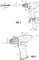
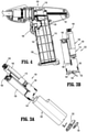
FIG. 1 is a side view illustrating a hand-held electromechanical surgical instrument including a handle assembly, with a surgical instrument module shown separated, a shaft portion coupled to the handle assembly, and a surgical end effector coupled to the shaft portion; -
FIG. 2 is a partial perspective view illustrating a handle housing of the handle assembly ofFIG. 1 ; -
FIG. 3A is a perspective view, with parts separated, illustrating the surgical instrument module ofFIG. 2 including a power assembly and an outer shell; -
FIG. 3B is an assembled front view illustrating the power assembly of the instrument module ofFIG. 3A ; -
FIG. 4 is a side view, with a housing half of the handle housing removed, illustrating internal components of the handle assembly; -
FIG. 5 is a perspective view illustrating a motor, an elongate ring gear, and outputs of the instrument module ofFIG. 3A ; -
FIG. 6 is a perspective view, with the elongate ring gear shown in phantom, illustrating a plurality of planetary gear assemblies of the instrument module ofFIG. 3A ; -
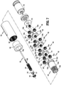
FIG. 7 is a perspective view, with parts separated, of the components shown inFIG. 5 ; -
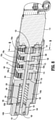
FIG. 8 is a cross-sectional view taken along line 8-8 inFIG. 5 ; -
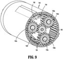
FIG. 9 is a cross-sectional view taken along line 9-9 inFIG. 8 ; and -
FIG. 10 illustrates four discrete surgical instruments all operable with the instrument module ofFIGS. 3A-3B . - Embodiments of the presently disclosed surgical instruments including handle assemblies thereof are described in detail with reference to the drawings, in which like reference numerals designate identical or corresponding elements in each of the several views. As used herein the term "distal" refers to that portion of the surgical instrument, or component thereof, farther from the user, while the term "proximal" refers to that portion of the surgical instrument, or component thereof, closer to the user.
- As will be described in detail below, provided is a surgical instrument module configured for receipt in a handle assembly of a plurality of discrete hand-held surgical instruments. The instrument module may be reusable and is configured to operate various functions of a plurality of different types of surgical end effectors, such as, for example, a linear stapler, a circular stapler, a hernia tacker, and a small-diameter vascular stapler. The surgical instrument module has two outputs with each operably coupled to the same motor of the surgical instrument module. A high-speed/low-torque output may be disposed concentrically within a high-torque/low-speed output. The outputs are rotated simultaneously by the motor, but each at a different speed and torque from the other. Depending on the surgical instrument in which the instrument module is received and operably engaged with, either the high-speed/low-torque output or the high-torque/low-speed output of the instrument module selectively engages a corresponding driven component (e.g., a rod, screw, rack, gear, or the like) of the selected surgical instrument. As such, the same instrument module may be used in a variety of surgical instruments despite each of the surgical instruments having discrete power and speed requirements. Other features and benefits of the disclosed surgical instruments are further detailed below.
- With reference to
FIGS. 1 and 2 , a surgical instrument, in accordance with an embodiment of the present disclosure, is generally designated as 10, and is in the form of a powered hand-held electromechanical linear stapler configured for selective coupling thereto of asurgical end effector 20. Theend effector 20 is configured for actuation and manipulation by thelinear stapler 10. The hand-held electromechanicalsurgical instrument 10 includes ahandle assembly 100, aknob housing 102 coupled to thehandle assembly 100, and ashaft portion 104 extending distally from theknob housing 102 and configured for selective connection with a surgical attachment, such as, for example, theend effector 20. - The
handle assembly 100 includes a disposable andsterile handle housing 110 having a body, such as, for example, abarrel portion 118, ahandle portion 108 extending perpendicularly downward from thebarrel portion 118 or transversely and proximally from thebarrel portion 118, and a hingeddoor 120 pivotably coupled to thehandle portion 108. Thedoor 120 is selectively opened and closed to allow for the insertion or removal of a non-sterile or sterilesurgical instrument module 122. Thehandle portion 108 and thedoor 120 each have an inner periphery collectively defining a sterile barrier for thesurgical instrument module 122 upon closing thedoor 120. In aspects, a proximal end portion or any suitable location of thebarrel portion 118 may have a clear window (not shown) to allow for viewing of a display (e.g., an LCD, not shown). - The
handle assembly 100 has afire switch 106 configured and adapted to actuate the various functions of theend effector 20. Thefire switch 106 may be constructed as a toggle bar pivotably coupled to thehandle portion 108 of thehandle housing 110. An activation of thefire switch 106 activates a motor 112 (FIGS. 3A and 3B ) to advance or retract a firing rod (not explicitly shown) of thesurgical instrument 10 depending on whether a top button or a bottom button of thefire switch 106 is actuated. The firing rod is coupled to a drive assembly (not explicitly shown) of the end effector 20 (which includes a knife rod and an actuation sled), such that advancement of the firing rod advances the drive assembly of theend effector 20, which closesjaw members end effector 20 and fires theend effector 20 when asafety switch 116 is in an actuated state. - The
handle assembly 100 has anarticulation switch 114 extending transversely through thehandle portion 108 and protruding outwardly from left and right sides of thehandle portion 108. Thearticulation switch 114 is configured to actuate an articulation of the end effector 20 (e.g., move theend effector 20 along a horizontal plane between a position coaxial with theshaft portion 104 and multiple positions out of alignment with the shaft portion 104). Theknob housing 102 is rotatably coupled to thehandle housing 110 and has theshaft portion 104 non-rotationally coupled thereto. As such, a manual rotation of theknob housing 102 results in a corresponding rotation of the end effector 20 (e.g., theend effector 20 rotates about a central longitudinal axis "X" defined by the shaft portion 104). - With reference to
FIGS. 1 ,3A, 3B, and 4 , thesurgical instrument module 122 of thehandle assembly 100 includes a sterileouter shell 128 and areusable power assembly 130 configured for removably receipt in theouter shell 128. Theouter shell 128 has acover 132 received in an open bottom end of theouter shell 128, and a spring-loadedpull tab 134 to facilitate removal of thecover 132. - The
power assembly 130 of theinstrument module 122 includes themotor 112, such as, for example, an electrical drive motor, which is electrically connected or wirelessly connected to a printedcircuit board 136 and abattery 138. In aspects, thebattery 138 may include a boost circuit and may be rechargeable (e.g., wirelessly). Thebattery 138 has acard edge connector 140 configured for detachable receipt of acard edge header 142 of thehandle assembly 100 to allow for communication from thefire switch 106, thesafety switch 116, thearticulation switch 114, and an articulation encoder to thebattery 138. The printedcircuit board 136 may include aUSB charging connector 144 to allow for thebattery 138 to be recharged with a USB charger or wirelessly (e.g., via induction). In aspects, the printedcircuit board 136 may have a motor controller or a processor. - The
instrument module 122 further includes agearbox 146, such as, for example, a planetary gearbox, operably coupled to thedrive motor 112, and first andsecond outputs 148, 150 (FIG. 5 ) drivingly coupled to thegearbox 146 and configured to rotate about a longitudinal axis defined by thegearbox 146. Thegear box 146 is configured to transfer power from themotor 112 into a rotation of thefirst output 148 at a high-torque and low-speed, and a rotation of thesecond output 150 at a high-speed and low-torque. Rotation of theoutputs motor 112 functions to drive shafts and/or gear components of thehandle assembly 100 in order to perform the various operations of theend effector 20. For example, themotor 112 is configured to move thejaw members end effector 20 relative to one another and to fire staples from theend effector 20. - For a more detailed description of the various components responsible for transferring rotation of the
outputs end effector 20, reference may be made toU.S. Provisional Application No. 62/944,400, filed on December 6, 2019 - With reference to
FIGS. 5-9 , further details of the various components of theinstrument module 122 will now be described. Themotor 112 has a rotatable motor shaft 152 (FIG. 7 ) to which amain sun gear 154 is non-rotatably fixed such that themain sun gear 154 rotates with themotor shaft 152 about a longitudinal axis defined by themotor shaft 152. Thegear box 146 includes a plurality ofplanetary gear assemblies elongate ring gear 164 disposed about and operably coupled to the plurality ofplanetary gear assemblies - The first
planetary gear assembly 156 is operably coupled to themain sun gear 154 such that the firstplanetary gear assembly 156 rotates about the longitudinal axis of themotor shaft 152 in response to a rotation of themain sun gear 154. The firstplanetary gear assembly 156 increases the torque output of themotor 112 while reducing the output rotational speed. The firstplanetary gear assembly 156 includes afirst carrier 168, afirst sun gear 166, and a plurality ofplanetary gears first carrier 168 has a plurality (e.g., three) ofpins first sun gear 166 is rotationally fixed to a distal side of thefirst carrier 168 and centrally aligned with the longitudinal axis of themotor shaft 152. Theplanetary gears respective pins first carrier 168. Theplanetary gears main sun gear 154 to rotate in response to a rotation of themain sun gear 154. As will be described, theelongate ring gear 164 is rotationally fixed relative to the outer shell 128 (FIG. 3A ) such that the firstplanetary gear assembly 156 rotates as a unit about the longitudinally axis of themotor shaft 152 in response to a rotation of themain sun gear 154. - The second
planetary gear assembly 158 includes asecond carrier 170, asecond sun gear 172, and a plurality ofplanetary gears planetary gear assembly 158 has an increased torque output and reduced rotational speed output relative to the firstplanetary gear assembly 156. Thesecond carrier 170 has a plurality (e.g., three) ofpins second sun gear 172 is rotationally fixed to a distal side of thesecond carrier 170 and centrally aligned with the longitudinal axis of themotor shaft 152. Theplanetary gears planetary gear assembly 158 are rotatably coupled to therespective pins second carrier 170. Theplanetary gears first sun gear 166 of the firstplanetary gear assembly 156 and the fixedelongate ring gear 164 such that the secondplanetary gear assembly 158 rotates in response to a rotation of the firstplanetary gear assembly 156. - The third
planetary gear assembly 160 includes athird carrier 174, athird sun gear 176, and a plurality ofplanetary gears planetary gear assembly 160 has an increased torque output and reduced rotational speed output relative to the secondplanetary gear assembly 158. Thethird carrier 174 has a plurality (e.g., three) ofpins third sun gear 176 is rotationally fixed to a distal side of thethird carrier 174 and centrally aligned with the longitudinal axis of themotor shaft 152. Theplanetary gears planetary gear assembly 160 are rotatably coupled to therespective pins third carrier 174. Theplanetary gears planetary gear assembly 160 are in meshing engagement with thesecond sun gear 172 of the secondplanetary gear assembly 158 and theelongate ring gear 164 such that the thirdplanetary gear assembly 160 rotates as a unit in response to a rotation of the secondplanetary gear assembly 158. - The fourth
planetary gear assembly 162 includes afourth carrier 178 and a plurality ofplanetary gears planetary gear assembly 162 has an increased torque output and reduced rotational speed output relative to the thirdplanetary gear assembly 160. Thefourth carrier 178 is connected to, monolithically formed with, or otherwise non-rotatably coupled to a proximal end of thefirst output 148 and has a plurality (e.g., three) ofpins planetary gears planetary gear assembly 162 are rotatably coupled to therespective pins fourth carrier 178. Theplanetary gears planetary gear assembly 162 are in meshing engagement with thethird sun gear 176 of the thirdplanetary gear assembly 160 and theelongate ring gear 164 such that the fourthplanetary gear assembly 162 and thefirst output 148 rotate together in response to a rotation of the thirdplanetary gear assembly 160. It is contemplated that thegear box 146 may include more or less than the four planetary gear assemblies and/or other types of gears. - With continued reference to
FIGS. 5-9 , thefirst output 148 is configured to generate a relatively high torque (e.g., about 625 oz-in) and a relatively low speed (e.g., 24 rpm) and includes acylindrical body 148a received in a distal end portion of theelongate ring gear 164, and agear 148b, such as, for example, a pinion gear formed with a distal end portion of thecylindrical body 148a. Thepinion gear 148b of thefirst output 148 is configured to be selectively operably coupled to a driven member (not explicitly shown) of a first type of surgical end effector, such as, for example, surgical end effector 20 (FIGS. 1 and10 ) of thelinear stapler 10 or a surgical end effector 300 (FIG. 10 ) of a circular stapler 310 (FIG. 10 ). It is contemplated that handleassemblies surgical instruments pinion gear 148b upon receipt of thesurgical instrument module 122 in therespective handle assembly - The
surgical instrument module 122 further includes adrive shaft 180 having aproximal end portion 180a non-rotatably coupled to the secondplanetary gear assembly 158 such that thedrive shaft 180 is configured to rotate with the secondplanetary gear assembly 158. In particular, theproximal end portion 180a of thedrive shaft 180 is received within and rotationally fixed to thesecond sun gear 172 of the secondplanetary gear assembly 158. Thedrive shaft 180 has adistal end portion 180b extending longitudinally through the third and fourthplanetary gear assemblies distal end portion 180b of thedrive shaft 180 may have a non-circular cross-sectional shape, such as, for example, a tri-lobe shape. - The
second output 150 is attached to thedistal end portion 180b of thedrive shaft 180 and is configured to rotate with thedrive shaft 180 about a longitudinal axis of thedrive shaft 180. Thesecond output 150 is configured to generate a relatively low torque (e.g., 25 oz-in) and a relatively high speed (e.g., 600 rpm) and includes asocket 151 that is configured to operably couple to a corresponding driven element (not explicitly shown) of a different type of surgical end effector than thefirst output 148. For example, thesecond output 150 of thesurgical instrument module 122 may be configured to carry out functions of a surgical end effector 400 (FIG. 10 ) of ahernia tacker 410 or a surgical end effector 510 (FIG. 10 ) of a small-diameter vascular stapler 500 (FIG. 10 ). It is contemplated that the handle assemblies or other components of thesurgical instruments socket 151 upon receipt of thesurgical instrument module 122 in the respective handle housing. - The
second output 150 is concentrically disposed within thefirst output 148 and is configured to rotate simultaneously with thefirst output 148 in response to an activation of the same motor, namely themotor 112. However, as noted above, the first andsecond outputs second output 150 is received in anelongate cavity 182 defined in thecylindrical body 148a of thefirst output 148. A biasingmember 184 is disposed within thecavity 182 and captured between thesecond output 150 and an inner surface of thecylindrical body 148a of thefirst output 148. The biasingmember 184 is configured to distally-bias thesecond output 150 into a position in which thesecond output 150 is concentric within thefirst output 148. The biasingmember 184 ensures that even if thesocket 151 of thesecond output 150 is out of radial alignment with the driven element of the end effector assembly that thesocket 151 will engage the driven element as thesecond output 150 rotates thesocket 151 into radial alignment with the driven element. - With continued reference to
FIGS. 5-9 , theelongate ring gear 164 of thegear box 146 encapsulates each of theplanetary gear assemblies FIG. 3A ) and themotor 112. Theelongate ring gear 164 has an annular inner surface defining a plurality of longitudinally-extendingteeth 186 that are in meshing engagement with the planetary gears of each of theplanetary gear assemblies first bushing 188 may be provided to capture thefirst output 148 in theelongate ring gear 164 and asecond bushing 190 may be provided to capture thesecond output 150 in thefirst output 148. - In operation, a surgical instrument is selected that is suitable for an operation to be performed. For example, the linear stapler 10 (
FIG. 10 ) may be selected. Thelinear stapler 10 is typically used for stapling a type of tissue that is more suitable to receiving staples that are deployed with a high torque and at a low speed. Thesurgical instrument module 122 is inserted into thehandle housing 110 of thelinear stapler 10, whereby thepinion gear 148b of thefirst output 148 operably engages a driven element, such as a rack 161 (FIG. 4 ) or a corresponding pinion gear of thehandle assembly 100 of thelinear stapler 10. In aspects, a sterile, funnel-shaped insertion guide may be implemented to assist in passing thesurgical instrument module 122 into thehandle housing 110. When the insertion guide is removed, thehandle housing 110 remains sterile through this aseptic transfer procedure. - With the
instrument module 122 disposed within thehandle housing 110, thedoor 120 is closed, thereby sealing theinstrument module 122 in thesterile handle portion 108. Further, thecard edge header 142 of the printedcircuit board 126 of thehandle assembly 100 is connected to thecard edge connector 140 of theinstrument module 130. - To operate the
surgical end effector 20 of thelinear stapler 10, the fire switch 106 (FIG. 1 ) may be toggled, whereby thebattery 138 of theinstrument module 122 provides power to themotor 112, which drives a rotation, in turn, of the first, second, third, and fourthplanetary gear assemblies planetary gear assemblies pinion gear 148b of thefirst output 148 compared to the torque and speed originating from themotor 112. The high-torque, low-speed output by thefirst output 148 results in the advancement of staples from theend effector 20 into tissue with a high force and at a low speed. - If a different surgical procedure is to be performed, for example, a hernia repair procedure, the hernia tacker 410 (
FIG. 10 ) may be selected for use rather than thelinear stapler 10. To properly treat tissue, thehernia tacker 410 demands less torque but a higher actuation speed than thelinear stapler 10. Theinstrument module 122 is inserted into ahandle portion 412 of thehernia tacker 410, whereby thesocket 151 of thesecond output 150 engages a driven element (e.g., a rod) of thehernia tacker 410. - To operate the
surgical end effector 400 of thehernia tacker 410, afire switch 414 of thehernia tacker 410 may be toggled, whereby thebattery 138 of theinstrument module 122 provides power to themotor 112, which drives a rotation, in turn, of the first and secondplanetary gear assemblies drive shaft 180 is fixed to thesecond sun gear 172 of the secondplanetary gear assembly 158, thedrive shaft 180 rotates with the rotation of the secondplanetary gear assembly 158. Thesecond output 150, which is non-rotatably attached to thedistal end portion 180b of thedrive shaft 180, rotates with thedrive shaft 180 to effect a function of thehernia tacker 410, such as a deployment of a surgical tack into tissue at a low torque and a high speed. - It is contemplated that each of the first and second drive outputs 148, 150 may be simultaneously coupled to two distinct driven elements of a particular surgical instrument to perform discrete functions of the surgical instrument.
- Any of the components described herein may be fabricated from either metals, plastics, resins, composites or the like taking into consideration strength, durability, wearability, weight, resistance to corrosion, ease of manufacturing, cost of manufacturing, and the like. Any of the gears disclosed herein may be configured as any suitable gear, such as bevel gears, spur gears, spiral gears, worm gears, or the like.
- It will be understood that various modifications may be made to the embodiments of the presently disclosed surgical instruments and surgical instrument modules. Therefore, the above description should not be construed as limiting, but merely as exemplifications of embodiments. Those skilled in the art will envision other modifications within the scope and spirit of the present disclosure.
- The invention may be described by reference to the following numbered paragraphs:-
- 1. A surgical instrument module for powering surgical end effectors, the surgical instrument module comprising:
- a motor having a rotatable motor shaft defining a longitudinal axis;
- a main sun gear fixed to the motor shaft and configured to rotate with the motor shaft;
- a first planetary gear assembly operably coupled to the main sun gear such that the first planetary gear assembly rotates about the longitudinal axis in response to a rotation of the main sun gear;
- a second planetary gear assembly operably coupled to the first planetary gear assembly such that the second planetary gear assembly rotates in response to the rotation of the first planetary gear assembly;
- a drive shaft non-rotatably coupled to the second planetary gear assembly such that the drive shaft rotates with the second planetary gear assembly;
- a third planetary gear assembly operably coupled to the second planetary gear assembly such that the third planetary gear assembly rotates in response to the rotation of the second planetary gear assembly;
- a fourth planetary gear assembly operably coupled to the third planetary gear assembly such that the fourth planetary gear assembly rotates in response to the rotation of the third planetary gear assembly;
- a high-torque output configured to be operably coupled to a driven member of a first surgical end effector, the high-torque output gear being non-rotatably coupled to the fourth planetary gear assembly such that the high-torque output rotates with the fourth planetary gear assembly; and
- a high-speed output configured to be operably coupled to a driven member of a second surgical end effector, the high-speed output being non-rotatably coupled to the drive shaft such that the high-speed output rotates with the drive shaft.
- 2. The surgical instrument module according to
paragraph 1, wherein the high-speed output is concentrically disposed within the high-torque output. - 3. The surgical instrument module according to paragraph 2, wherein the high-speed and high-torque outputs are configured to rotate simultaneously in response to an activation of the motor.
- 4. The surgical instrument module according to
paragraph 1, wherein the high-torque output includes a pinion gear and the high-speed output includes a socket. - 5. The surgical instrument module according to
paragraph 1, wherein the drive shaft extends longitudinally through the third and fourth planetary gear assemblies. - 6. The surgical instrument module according to paragraph 5, wherein the drive shaft has a proximal end portion fixed to the second planetary gear assembly, and a distal end portion disposed within and rotatable relative to the high-torque output.
- 7. The surgical instrument module according to
paragraph 1, wherein the high-torque output defines a cavity therein, and the high-speed output is received in the cavity. - 8. The surgical instrument module according to paragraph 7, wherein the high-speed output is configured to move longitudinally relative to and along the drive shaft.
- 9. The surgical instrument module according to
paragraph 8, further comprising a biasing member captured between the high-speed output and an inner surface of the high-torque output, wherein the biasing member is configured to distally-bias the high-speed output. - 10. The surgical instrument module according to
paragraph 1, further comprising an elongate ring gear in meshing engagement with each of the planetary gear assemblies. - 11. The surgical instrument module according to
paragraph 10, wherein each of the planetary gear assemblies is disposed within the elongate ring gear. - 12. The surgical instrument module according to
paragraph 10, wherein the elongate ring gear is rotationally fixed relative to the motor. - 13. The surgical instrument module according to
paragraph 1, wherein the first planetary gear assembly includes:- a first carrier;
- a plurality of planetary gears rotatably coupled to the first carrier and operably engaged with the main sun gear; and
- a first sun gear rotationally fixed to the first carrier.
- 14. The surgical instrument module according to paragraph 13, wherein the second planetary gear assembly includes:
- a second carrier;
- a plurality of planetary gears rotatably coupled to the second carrier and operably engaged with the first sun gear; and
- a second sun gear rotationally fixed to the second carrier.
- 15. The surgical instrument module according to paragraph 14, wherein the drive shaft has a proximal end portion disposed within and rotationally fixed to the second sun gear.
- 16. The surgical instrument module according to paragraph 14, wherein the third planetary gear assembly includes:
- a third carrier;
- a plurality of planetary gears rotatably coupled to the third carrier and operably engaged with the second sun gear; and
- a third sun gear rotationally fixed to the third carrier.
- 17. The surgical instrument module according to paragraph 16, wherein the fourth planetary gear assembly includes:
- a fourth carrier non-rotationally fixed to the high-torque output; and
- a plurality of planetary gears rotatably coupled to the fourth carrier and operably engaged with the third sun gear.
- 18. The surgical instrument module according to paragraph 17, further comprising an elongate ring gear in meshing engagement with the plurality of planetary gears of each of the planetary gear assemblies.
- 19. The surgical instrument module according to
paragraph 18, further comprising an outer shell in which the elongate ring gear is received, wherein the elongate ring gear is non-rotatable relative to the outer shell. - 20. The surgical instrument module according to paragraph 19, further comprising:
- a battery received in the outer shell and configured to power the motor; and
- a printed circuit board received in the outer shell and in communication with the battery and the motor.
Claims (15)
- A surgical instrument module for powering surgical end effectors, the surgical instrument module comprising:a motor having a rotatable motor shaft defining a longitudinal axis;a main sun gear fixed to the motor shaft and configured to rotate with the motor shaft;a first planetary gear assembly operably coupled to the main sun gear such that the first planetary gear assembly rotates about the longitudinal axis in response to a rotation of the main sun gear;a second planetary gear assembly operably coupled to the first planetary gear assembly such that the second planetary gear assembly rotates in response to the rotation of the first planetary gear assembly;a drive shaft non-rotatably coupled to the second planetary gear assembly such that the drive shaft rotates with the second planetary gear assembly;a third planetary gear assembly operably coupled to the second planetary gear assembly such that the third planetary gear assembly rotates in response to the rotation of the second planetary gear assembly;a fourth planetary gear assembly operably coupled to the third planetary gear assembly such that the fourth planetary gear assembly rotates in response to the rotation of the third planetary gear assembly;a high-torque output configured to be operably coupled to a driven member of a first surgical end effector, the high-torque output gear being non-rotatably coupled to the fourth planetary gear assembly such that the high-torque output rotates with the fourth planetary gear assembly; anda high-speed output configured to be operably coupled to a driven member of a second surgical end effector, the high-speed output being non-rotatably coupled to the drive shaft such that the high-speed output rotates with the drive shaft.
- The surgical instrument module according to claim 1, wherein the high-speed output is concentrically disposed within the high-torque output; preferably wherein the high-speed and high-torque outputs are configured to rotate simultaneously in response to an activation of the motor.
- The surgical instrument module according to claim 1 or claim 2, wherein the high-torque output includes a pinion gear and the high-speed output includes a socket; and/or wherein the drive shaft extends longitudinally through the third and fourth planetary gear assemblies.
- The surgical instrument module according to claim 3, wherein the drive shaft has a proximal end portion fixed to the second planetary gear assembly, and a distal end portion disposed within and rotatable relative to the high-torque output.
- The surgical instrument module according to any preceding claim, wherein the high-torque output defines a cavity therein, and the high-speed output is received in the cavity; preferably wherein the high-speed output is configured to move longitudinally relative to and along the drive shaft; preferably still further comprising a biasing member captured between the high-speed output and an inner surface of the high-torque output, wherein the biasing member is configured to distally-bias the high-speed output.
- The surgical instrument module according to any preceding claim, further comprising an elongate ring gear in meshing engagement with each of the planetary gear assemblies; preferably wherein each of the planetary gear assemblies is disposed within the elongate ring gear.
- The surgical instrument module according to claim 6, wherein the elongate ring gear is rotationally fixed relative to the motor.
- The surgical instrument module according to any preceding claim, wherein the first planetary gear assembly includes:a first carrier;a plurality of planetary gears rotatably coupled to the first carrier and operably engaged with the main sun gear; anda first sun gear rotationally fixed to the first carrier.
- The surgical instrument module according to claim 8, wherein the second planetary gear assembly includes:a second carrier;a plurality of planetary gears rotatably coupled to the second carrier and operably engaged with the first sun gear; anda second sun gear rotationally fixed to the second carrier.
- The surgical instrument module according to claim 9, wherein the drive shaft has a proximal end portion disposed within and rotationally fixed to the second sun gear.
- The surgical instrument module according to claim 9 or claim 10, wherein the third planetary gear assembly includes:a third carrier;a plurality of planetary gears rotatably coupled to the third carrier and operably engaged with the second sun gear; anda third sun gear rotationally fixed to the third carrier.
- The surgical instrument module according to claim 11, wherein the fourth planetary gear assembly includes:a fourth carrier non-rotationally fixed to the high-torque output; anda plurality of planetary gears rotatably coupled to the fourth carrier and operably engaged with the third sun gear.
- The surgical instrument module according to claim 12, further comprising an elongate ring gear in meshing engagement with the plurality of planetary gears of each of the planetary gear assemblies.
- The surgical instrument module according to claim 13, further comprising an outer shell in which the elongate ring gear is received, wherein the elongate ring gear is non-rotatable relative to the outer shell.
- The surgical instrument module according to claim 14, further comprising:a battery received in the outer shell and configured to power the motor; anda printed circuit board received in the outer shell and in communication with the battery and the motor.
Applications Claiming Priority (2)
| Application Number | Priority Date | Filing Date | Title |
|---|---|---|---|
| US202063064977P | 2020-08-13 | 2020-08-13 | |
| US17/090,093 US11871924B2 (en) | 2018-09-21 | 2020-11-05 | Hand-held surgical instruments |
Publications (2)
| Publication Number | Publication Date |
|---|---|
| EP3954304A1 true EP3954304A1 (en) | 2022-02-16 |
| EP3954304B1 EP3954304B1 (en) | 2025-10-15 |
Family
ID=73726681
Family Applications (1)
| Application Number | Title | Priority Date | Filing Date |
|---|---|---|---|
| EP20211924.4A Active EP3954304B1 (en) | 2020-08-13 | 2020-12-04 | Hand-held surgical instruments |
Country Status (3)
| Country | Link |
|---|---|
| EP (1) | EP3954304B1 (en) |
| JP (1) | JP7636162B2 (en) |
| CN (1) | CN114073555B (en) |
Citations (5)
| Publication number | Priority date | Publication date | Assignee | Title |
|---|---|---|---|---|
| EP2676615A2 (en) * | 2012-06-19 | 2013-12-25 | Covidien LP | Apparatus for endoscopic procedures |
| EP3011911A1 (en) * | 2013-06-20 | 2016-04-27 | Reach Surgical. Inc | Surgical procedure instrument and drive device thereof |
| CA3073178A1 (en) * | 2017-08-17 | 2019-02-21 | Stryker Corporation | Surgical handpiece for measuring depth of bore holes and related accessories |
| US10441281B2 (en) * | 2013-08-23 | 2019-10-15 | Ethicon Llc | surgical instrument including securing and aligning features |
| GB2574099A (en) * | 2018-03-23 | 2019-11-27 | Kaseum Holdings Ltd | Downhole tool |
Family Cites Families (5)
| Publication number | Priority date | Publication date | Assignee | Title |
|---|---|---|---|---|
| JPS49104062A (en) * | 1973-02-13 | 1974-10-02 | ||
| US7416101B2 (en) * | 2006-01-31 | 2008-08-26 | Ethicon Endo-Surgery, Inc. | Motor-driven surgical cutting and fastening instrument with loading force feedback |
| JP6453308B2 (en) * | 2013-04-16 | 2019-01-16 | エシコン・エンド−サージェリィ・インコーポレイテッドEthicon Endo−Surgery,Inc. | Modular electric surgical instrument with status indication device |
| JP6416259B2 (en) * | 2013-08-23 | 2018-10-31 | エシコン エルエルシー | Motor-powered articulatable surgical instrument |
| US9895148B2 (en) * | 2015-03-06 | 2018-02-20 | Ethicon Endo-Surgery, Llc | Monitoring speed control and precision incrementing of motor for powered surgical instruments |
-
2020
- 2020-12-03 CN CN202011405170.XA patent/CN114073555B/en active Active
- 2020-12-03 JP JP2020200799A patent/JP7636162B2/en active Active
- 2020-12-04 EP EP20211924.4A patent/EP3954304B1/en active Active
Patent Citations (5)
| Publication number | Priority date | Publication date | Assignee | Title |
|---|---|---|---|---|
| EP2676615A2 (en) * | 2012-06-19 | 2013-12-25 | Covidien LP | Apparatus for endoscopic procedures |
| EP3011911A1 (en) * | 2013-06-20 | 2016-04-27 | Reach Surgical. Inc | Surgical procedure instrument and drive device thereof |
| US10441281B2 (en) * | 2013-08-23 | 2019-10-15 | Ethicon Llc | surgical instrument including securing and aligning features |
| CA3073178A1 (en) * | 2017-08-17 | 2019-02-21 | Stryker Corporation | Surgical handpiece for measuring depth of bore holes and related accessories |
| GB2574099A (en) * | 2018-03-23 | 2019-11-27 | Kaseum Holdings Ltd | Downhole tool |
Also Published As
| Publication number | Publication date |
|---|---|
| CN114073555A (en) | 2022-02-22 |
| CN114073555B (en) | 2025-06-27 |
| EP3954304B1 (en) | 2025-10-15 |
| JP7636162B2 (en) | 2025-02-26 |
| JP2022032917A (en) | 2022-02-25 |
Similar Documents
| Publication | Publication Date | Title |
|---|---|---|
| US12274439B2 (en) | Hand-held surgical instruments | |
| US11690618B2 (en) | Handheld electromechanical surgical instruments | |
| US11510669B2 (en) | Hand-held surgical instruments | |
| US11006953B2 (en) | Apparatus for endoscopic procedures | |
| CN101272740B (en) | surgical device | |
| US12295571B2 (en) | Powered surgical tack applier | |
| EP2668913A2 (en) | Hand held surgical handle assembly, surgical adapters for use between surgical handle assembly and surgical loading units and methods of use | |
| US11801050B2 (en) | Hand-held surgical instruments | |
| JP2025020425A (en) | Powered surgical tack applier | |
| US20210169476A1 (en) | Hand-held surgical instruments | |
| EP3954304B1 (en) | Hand-held surgical instruments |
Legal Events
| Date | Code | Title | Description |
|---|---|---|---|
| PUAI | Public reference made under article 153(3) epc to a published international application that has entered the european phase |
Free format text: ORIGINAL CODE: 0009012 |
|
| STAA | Information on the status of an ep patent application or granted ep patent |
Free format text: STATUS: THE APPLICATION HAS BEEN PUBLISHED |
|
| AK | Designated contracting states |
Kind code of ref document: A1 Designated state(s): AL AT BE BG CH CY CZ DE DK EE ES FI FR GB GR HR HU IE IS IT LI LT LU LV MC MK MT NL NO PL PT RO RS SE SI SK SM TR |
|
| STAA | Information on the status of an ep patent application or granted ep patent |
Free format text: STATUS: REQUEST FOR EXAMINATION WAS MADE |
|
| 17P | Request for examination filed |
Effective date: 20220816 |
|
| RBV | Designated contracting states (corrected) |
Designated state(s): AL AT BE BG CH CY CZ DE DK EE ES FI FR GB GR HR HU IE IS IT LI LT LU LV MC MK MT NL NO PL PT RO RS SE SI SK SM TR |
|
| GRAP | Despatch of communication of intention to grant a patent |
Free format text: ORIGINAL CODE: EPIDOSNIGR1 |
|
| STAA | Information on the status of an ep patent application or granted ep patent |
Free format text: STATUS: GRANT OF PATENT IS INTENDED |
|
| RIC1 | Information provided on ipc code assigned before grant |
Ipc: A61B 17/29 20060101ALN20241112BHEP Ipc: A61B 17/00 20060101ALN20241112BHEP Ipc: A61B 17/068 20060101ALI20241112BHEP Ipc: A61B 17/115 20060101ALI20241112BHEP Ipc: A61B 17/072 20060101AFI20241112BHEP |
|
| RIC1 | Information provided on ipc code assigned before grant |
Ipc: A61B 17/29 20060101ALN20241115BHEP Ipc: A61B 17/00 20060101ALN20241115BHEP Ipc: A61B 17/068 20060101ALI20241115BHEP Ipc: A61B 17/115 20060101ALI20241115BHEP Ipc: A61B 17/072 20060101AFI20241115BHEP |
|
| INTG | Intention to grant announced |
Effective date: 20241203 |
|
| RIC1 | Information provided on ipc code assigned before grant |
Ipc: A61B 17/29 20060101ALN20241125BHEP Ipc: A61B 17/00 20060101ALN20241125BHEP Ipc: A61B 17/068 20060101ALI20241125BHEP Ipc: A61B 17/115 20060101ALI20241125BHEP Ipc: A61B 17/072 20060101AFI20241125BHEP |
|
| GRAJ | Information related to disapproval of communication of intention to grant by the applicant or resumption of examination proceedings by the epo deleted |
Free format text: ORIGINAL CODE: EPIDOSDIGR1 |
|
| STAA | Information on the status of an ep patent application or granted ep patent |
Free format text: STATUS: REQUEST FOR EXAMINATION WAS MADE |
|
| INTC | Intention to grant announced (deleted) | ||
| GRAP | Despatch of communication of intention to grant a patent |
Free format text: ORIGINAL CODE: EPIDOSNIGR1 |
|
| STAA | Information on the status of an ep patent application or granted ep patent |
Free format text: STATUS: GRANT OF PATENT IS INTENDED |
|
| RIC1 | Information provided on ipc code assigned before grant |
Ipc: A61B 17/29 20060101ALN20250424BHEP Ipc: A61B 17/00 20060101ALN20250424BHEP Ipc: A61B 17/068 20060101ALI20250424BHEP Ipc: A61B 17/115 20060101ALI20250424BHEP Ipc: A61B 17/072 20060101AFI20250424BHEP |
|
| INTG | Intention to grant announced |
Effective date: 20250509 |
|
| GRAS | Grant fee paid |
Free format text: ORIGINAL CODE: EPIDOSNIGR3 |
|
| GRAA | (expected) grant |
Free format text: ORIGINAL CODE: 0009210 |
|
| STAA | Information on the status of an ep patent application or granted ep patent |
Free format text: STATUS: THE PATENT HAS BEEN GRANTED |
|
| AK | Designated contracting states |
Kind code of ref document: B1 Designated state(s): AL AT BE BG CH CY CZ DE DK EE ES FI FR GB GR HR HU IE IS IT LI LT LU LV MC MK MT NL NO PL PT RO RS SE SI SK SM TR |
|
| REG | Reference to a national code |
Ref country code: GB Ref legal event code: FG4D Ref country code: CH Ref legal event code: F10 Free format text: ST27 STATUS EVENT CODE: U-0-0-F10-F00 (AS PROVIDED BY THE NATIONAL OFFICE) Effective date: 20251015 |
|
| REG | Reference to a national code |
Ref country code: IE Ref legal event code: FG4D |
|
| REG | Reference to a national code |
Ref country code: DE Ref legal event code: R096 Ref document number: 602020060432 Country of ref document: DE |
|
| PGFP | Annual fee paid to national office [announced via postgrant information from national office to epo] |
Ref country code: DE Payment date: 20251126 Year of fee payment: 6 |
|
| PGFP | Annual fee paid to national office [announced via postgrant information from national office to epo] |
Ref country code: FR Payment date: 20251120 Year of fee payment: 6 |
|
| REG | Reference to a national code |
Ref country code: NL Ref legal event code: MP Effective date: 20251015 |
|
| REG | Reference to a national code |
Ref country code: AT Ref legal event code: MK05 Ref document number: 1846231 Country of ref document: AT Kind code of ref document: T Effective date: 20251015 |
|
| PG25 | Lapsed in a contracting state [announced via postgrant information from national office to epo] |
Ref country code: NL Free format text: LAPSE BECAUSE OF FAILURE TO SUBMIT A TRANSLATION OF THE DESCRIPTION OR TO PAY THE FEE WITHIN THE PRESCRIBED TIME-LIMIT Effective date: 20251015 |
|
| PG25 | Lapsed in a contracting state [announced via postgrant information from national office to epo] |
Ref country code: ES Free format text: LAPSE BECAUSE OF FAILURE TO SUBMIT A TRANSLATION OF THE DESCRIPTION OR TO PAY THE FEE WITHIN THE PRESCRIBED TIME-LIMIT Effective date: 20251015 |
|
| REG | Reference to a national code |
Ref country code: LT Ref legal event code: MG9D |
|
| PG25 | Lapsed in a contracting state [announced via postgrant information from national office to epo] |
Ref country code: NO Free format text: LAPSE BECAUSE OF FAILURE TO SUBMIT A TRANSLATION OF THE DESCRIPTION OR TO PAY THE FEE WITHIN THE PRESCRIBED TIME-LIMIT Effective date: 20260115 |
|
| PG25 | Lapsed in a contracting state [announced via postgrant information from national office to epo] |
Ref country code: HR Free format text: LAPSE BECAUSE OF FAILURE TO SUBMIT A TRANSLATION OF THE DESCRIPTION OR TO PAY THE FEE WITHIN THE PRESCRIBED TIME-LIMIT Effective date: 20251015 Ref country code: AT Free format text: LAPSE BECAUSE OF FAILURE TO SUBMIT A TRANSLATION OF THE DESCRIPTION OR TO PAY THE FEE WITHIN THE PRESCRIBED TIME-LIMIT Effective date: 20251015 Ref country code: FI Free format text: LAPSE BECAUSE OF FAILURE TO SUBMIT A TRANSLATION OF THE DESCRIPTION OR TO PAY THE FEE WITHIN THE PRESCRIBED TIME-LIMIT Effective date: 20251015 |
|
| PG25 | Lapsed in a contracting state [announced via postgrant information from national office to epo] |
Ref country code: RS Free format text: LAPSE BECAUSE OF FAILURE TO SUBMIT A TRANSLATION OF THE DESCRIPTION OR TO PAY THE FEE WITHIN THE PRESCRIBED TIME-LIMIT Effective date: 20260115 |
|
| PG25 | Lapsed in a contracting state [announced via postgrant information from national office to epo] |
Ref country code: IS Free format text: LAPSE BECAUSE OF FAILURE TO SUBMIT A TRANSLATION OF THE DESCRIPTION OR TO PAY THE FEE WITHIN THE PRESCRIBED TIME-LIMIT Effective date: 20260215 |
|
| PG25 | Lapsed in a contracting state [announced via postgrant information from national office to epo] |
Ref country code: PT Free format text: LAPSE BECAUSE OF FAILURE TO SUBMIT A TRANSLATION OF THE DESCRIPTION OR TO PAY THE FEE WITHIN THE PRESCRIBED TIME-LIMIT Effective date: 20260216 |
|
| PG25 | Lapsed in a contracting state [announced via postgrant information from national office to epo] |
Ref country code: PL Free format text: LAPSE BECAUSE OF FAILURE TO SUBMIT A TRANSLATION OF THE DESCRIPTION OR TO PAY THE FEE WITHIN THE PRESCRIBED TIME-LIMIT Effective date: 20251015 |
|
| PG25 | Lapsed in a contracting state [announced via postgrant information from national office to epo] |
Ref country code: LV Free format text: LAPSE BECAUSE OF FAILURE TO SUBMIT A TRANSLATION OF THE DESCRIPTION OR TO PAY THE FEE WITHIN THE PRESCRIBED TIME-LIMIT Effective date: 20251015 |
|
| PG25 | Lapsed in a contracting state [announced via postgrant information from national office to epo] |
Ref country code: BG Free format text: LAPSE BECAUSE OF FAILURE TO SUBMIT A TRANSLATION OF THE DESCRIPTION OR TO PAY THE FEE WITHIN THE PRESCRIBED TIME-LIMIT Effective date: 20251015 |
|
| PG25 | Lapsed in a contracting state [announced via postgrant information from national office to epo] |
Ref country code: RO Free format text: LAPSE BECAUSE OF FAILURE TO SUBMIT A TRANSLATION OF THE DESCRIPTION OR TO PAY THE FEE WITHIN THE PRESCRIBED TIME-LIMIT Effective date: 20251015 |
|
| PG25 | Lapsed in a contracting state [announced via postgrant information from national office to epo] |
Ref country code: LT Free format text: LAPSE BECAUSE OF FAILURE TO SUBMIT A TRANSLATION OF THE DESCRIPTION OR TO PAY THE FEE WITHIN THE PRESCRIBED TIME-LIMIT Effective date: 20251015 |
|
| PG25 | Lapsed in a contracting state [announced via postgrant information from national office to epo] |
Ref country code: SM Free format text: LAPSE BECAUSE OF FAILURE TO SUBMIT A TRANSLATION OF THE DESCRIPTION OR TO PAY THE FEE WITHIN THE PRESCRIBED TIME-LIMIT Effective date: 20251015 |
|
| PG25 | Lapsed in a contracting state [announced via postgrant information from national office to epo] |
Ref country code: MC Free format text: LAPSE BECAUSE OF FAILURE TO SUBMIT A TRANSLATION OF THE DESCRIPTION OR TO PAY THE FEE WITHIN THE PRESCRIBED TIME-LIMIT Effective date: 20251015 |
|
| PG25 | Lapsed in a contracting state [announced via postgrant information from national office to epo] |
Ref country code: DK Free format text: LAPSE BECAUSE OF FAILURE TO SUBMIT A TRANSLATION OF THE DESCRIPTION OR TO PAY THE FEE WITHIN THE PRESCRIBED TIME-LIMIT Effective date: 20251015 |
|
| PG25 | Lapsed in a contracting state [announced via postgrant information from national office to epo] |
Ref country code: IT Free format text: LAPSE BECAUSE OF FAILURE TO SUBMIT A TRANSLATION OF THE DESCRIPTION OR TO PAY THE FEE WITHIN THE PRESCRIBED TIME-LIMIT Effective date: 20251015 |
|
| PG25 | Lapsed in a contracting state [announced via postgrant information from national office to epo] |
Ref country code: EE Free format text: LAPSE BECAUSE OF FAILURE TO SUBMIT A TRANSLATION OF THE DESCRIPTION OR TO PAY THE FEE WITHIN THE PRESCRIBED TIME-LIMIT Effective date: 20251015 |
|
| PG25 | Lapsed in a contracting state [announced via postgrant information from national office to epo] |
Ref country code: CZ Free format text: LAPSE BECAUSE OF FAILURE TO SUBMIT A TRANSLATION OF THE DESCRIPTION OR TO PAY THE FEE WITHIN THE PRESCRIBED TIME-LIMIT Effective date: 20251015 |
|
| REG | Reference to a national code |
Ref country code: CH Ref legal event code: H13 Free format text: ST27 STATUS EVENT CODE: U-0-0-H10-H13 (AS PROVIDED BY THE NATIONAL OFFICE) Effective date: 20260723 |
|
| PG25 | Lapsed in a contracting state [announced via postgrant information from national office to epo] |
Ref country code: SK Free format text: LAPSE BECAUSE OF FAILURE TO SUBMIT A TRANSLATION OF THE DESCRIPTION OR TO PAY THE FEE WITHIN THE PRESCRIBED TIME-LIMIT Effective date: 20251015 |
|
| PG25 | Lapsed in a contracting state [announced via postgrant information from national office to epo] |
Ref country code: SE Free format text: LAPSE BECAUSE OF FAILURE TO SUBMIT A TRANSLATION OF THE DESCRIPTION OR TO PAY THE FEE WITHIN THE PRESCRIBED TIME-LIMIT Effective date: 20251015 |