EP3954198A1 - Hedge cutter - Google Patents
Hedge cutter Download PDFInfo
- Publication number
- EP3954198A1 EP3954198A1 EP21189526.3A EP21189526A EP3954198A1 EP 3954198 A1 EP3954198 A1 EP 3954198A1 EP 21189526 A EP21189526 A EP 21189526A EP 3954198 A1 EP3954198 A1 EP 3954198A1
- Authority
- EP
- European Patent Office
- Prior art keywords
- casing
- hedge cutter
- circuit board
- motor
- assembly
- Prior art date
- Legal status (The legal status is an assumption and is not a legal conclusion. Google has not performed a legal analysis and makes no representation as to the accuracy of the status listed.)
- Granted
Links
Images




Classifications
-
- A—HUMAN NECESSITIES
- A01—AGRICULTURE; FORESTRY; ANIMAL HUSBANDRY; HUNTING; TRAPPING; FISHING
- A01G—HORTICULTURE; CULTIVATION OF VEGETABLES, FLOWERS, RICE, FRUIT, VINES, HOPS OR SEAWEED; FORESTRY; WATERING
- A01G3/00—Cutting implements specially adapted for horticultural purposes; Delimbing standing trees
- A01G3/04—Apparatus for trimming hedges, e.g. hedge shears
- A01G3/047—Apparatus for trimming hedges, e.g. hedge shears portable
-
- A—HUMAN NECESSITIES
- A01—AGRICULTURE; FORESTRY; ANIMAL HUSBANDRY; HUNTING; TRAPPING; FISHING
- A01G—HORTICULTURE; CULTIVATION OF VEGETABLES, FLOWERS, RICE, FRUIT, VINES, HOPS OR SEAWEED; FORESTRY; WATERING
- A01G3/00—Cutting implements specially adapted for horticultural purposes; Delimbing standing trees
- A01G3/04—Apparatus for trimming hedges, e.g. hedge shears
- A01G3/047—Apparatus for trimming hedges, e.g. hedge shears portable
- A01G3/053—Apparatus for trimming hedges, e.g. hedge shears portable motor-driven
Definitions
- the present invention relates to an outdoor garden instrument, in particular to a hedge cutter for pruning branches or leaves of hedges, or a hedge cutter wherein the cutting blade is driven by a motor to reciprocate.
- the hedge cutter is an outdoor garden instrument used to cut branches or leaves by means of a linearly reciprocating long and thin cutting blade or cutting rod so that hedges can be formed as expected.
- the cutting work is usually done in the following way: The worker holds a hedge cutter with two hands and moves the cutting blade along the shape of a hedge.
- electric hedge cutters are very popular. Since electric hedge cutters are held with two hands and are moved during operations, they are lighter and more compact than diesel hedge cutters.
- the rotary driving force output from the motor on a hedge cutter is usually converted by, for example, a gear reduction mechanism, into a larger torque and a lower speed.
- the object of the present invention is to provide an alternative electric garden instrument, in particular a hedge cutter, which eliminates or alleviates the above-mentioned technical problem or at least provides an available choice.
- one aspect of the present invention is a hedge cutter.
- the hedge cutter comprises a driving motor disposed in a casing, a transmission mechanism disposed in the casing and coupled with the driving motor, a blade arrangement extending from the casing and coupled with the transmission mechanism, and a printed circuit board assembly disposed in the casing and mounted at one end of the driving motor, wherein the shape of the printed circuit board assembly corresponds to the cross-section of the driving motor, and wherein the in-line arrangement of the driving motor and the printed circuit board assembly is perpendicular to the longitudinal axis of the blade arrangement.
- the present invention provides an electric garden instrument and the electric garden instrument comprises a driving motor assembly disposed in the casing, a transmission mechanism disposed in the casing and coupled with the driving motor assembly, a blade arrangement extending from the casing and coupled with the transmission mechanism, and a printed circuit board assembly mounted on the driving motor assembly, wherein a heat radiator is disposed between the driving motor assembly and the printed circuit board assembly.
- the printed circuit board assembly comprises a first printed circuit board, which is mounted at one end of the driving motor assembly away from the output shaft of the motor, and the heat radiator comprises a first heat radiator, which is disposed between the driving motor assembly and the first printed circuit board.
- the shape of the first printed circuit board corresponds to the shape of the cross-section of the driving motor assembly.
- the ratio of the area of the first printed circuit board to the cross-sectional area of the driving motor assembly is 0.7 to 1.5.
- the driving motor assembly, the first printed circuit board and the first heat radiator are arranged in line, and the first printed circuit board is positioned roughly parallel to the extension direction of the blade arrangement.
- the first heat radiator is a passive heat radiator and covers at least 50% of the area of the first printed circuit board.
- the printed circuit board assembly further comprises a second printed circuit board, and the second printed circuit board is mounted on a side of the driving motor assembly and is positioned perpendicular to the extension direction of the blade arrangement.
- a second heat radiator is disposed between the driving motor assembly and the second printed circuit board.
- the second heat radiator is a passive heat radiator and serves as a support of the second printed circuit board, and the second printed circuit board is at least partially accommodated in the second heat radiator.
- the printed circuit board assembly further comprises a third printed circuit board, and the third printed circuit board is mounted on a side of the driving motor assembly and is positioned to form an angle with the extension direction of the blade arrangement.
- the angle is in a range of 30° to 70°.
- a third heat radiator is disposed between the driving motor assembly and the third printed circuit board.
- the third heat radiator is a passive heat radiator and serves as a support of the third printed circuit board, and the third printed circuit board is at least partially accommodated in the third heat radiator.
- the driving motor assembly comprises a fan, the fan is arranged at one end of the driving motor assembly close to the output shaft of the motor, and is in the same in-line arrangement as the driving motor and the first printed circuit board.
- the transmission mechanism comprises a gear transmission mechanism, a belt transmission mechanism or a combination of the gear transmission mechanism and the belt transmission mechanism.
- the transmission mechanism is a gear transmission mechanism
- the gear transmission mechanism comprises a planetary gear or a bevel gear.
- the transmission mechanism comprises a planetary gear and a sun gear, and in addition, the transmission mechanism is in the same in-line arrangement as the driving motor assembly and the printed circuit board assembly, wherein the planetary gear comprises one stage of planetary gear or two stages of planetary gears.
- the casing comprises or is attached with a front handle and a rear handle
- a trigger for starting the driving motor assembly is disposed on either of the front handle and the rear handle
- a safety switch is disposed on either of the front handle and the rear handle
- the driving motor assembly rotates only when the trigger and the safety switch are both actuated.
- the rear handle can rotate relative to at least a part of the casing and perpendicular to the longitudinal axis of the blade arrangement.
- the barycenter of the electric garden instrument is roughly located at the front handle.
- the power supply of the electric garden instrument is a detachable battery pack, and the detachable battery pack is accommodated in or attached to the casing or attached to the front handle or the rear handle.
- the blade arrangement comprises at least a cutting rod, and the cutting rod comprises cutting edge teeth arranged on the two sides and having a sharp cutting edge portion, wherein the top of at least some cutting edge teeth close to the casing have a blunt tip.
- the upper top of the casing has projections suitable for accommodating the in-line arrangement comprising the printed circuit board assembly and the driving motor assembly.
- an exhaust port is disposed on the top of the casing to promote air circulation and improve the heat dissipation performance.
- the electric garden instrument may be a hedge cutter.
- the rear handle can at least rotate relative to at least a part of the casing and perpendicular to the longitudinal axis of the blade arrangement.
- the front handle can rotate around the mounting axis so that the angle of the front handle relative to the casing can be adjusted.
- the rear handle can rotate around the longitudinal axis of the hedge cutter.
- the present invention has many advantages.
- the in-line integration of the printed circuit board assembly and the driving motor is adopted in the present invention, and in addition, the motor fan and the driving mechanism may be in the same in-line arrangement as the printed circuit board assembly and the driving motor. Therefore, a compact design of the hedge cutter is provided and a light weight of the hedge cutter is enabled.
- the in-line arrangement of components makes it easy to put the barycenter of the hedge cutter at the front handle, and thus human-machine interactions are improved.
- the combination of the first stage planetary gear and double-sided sharp cutting edge teeth can provide not only a light and compact design, but also a satisfactory cutting/pruning performance.
- the arrangement including the driving motor and the printed circuit board assembly mounted at one end of the driving motor may be called an in-line arrangement.
- the arrangement includes the printed circuit board assembly, the heat radiator and/or the motor fan disposed between the driving motor and the printed circuit board assembly.
- the arrangement including the printed circuit board assembly, heat radiator, driving motor and/or motor fan may also be called an in-line arrangement.
- an in-line arrangement lies in that the components (printed circuit board assembly, heat radiator, driving motor and motor fan) in the arrangement are arranged in the axis direction, or arranged opposite to each other roughly in an in-line way (roughly having the same axis or roughly connected in series on the same axis), and thus a compact arrangement is formed.
- the transmission mechanism including the gears located between the integrated driving unit and the driven component (cutting rod) may also be in the same in-line arrangement as the printed circuit board assembly and the driving motor, and thus the overall structure, shape and size of the hedge cutter are more compact.
- a compact design enables components to occupy a small space.
- the compact design requires fewer components and mounting components so that the total weight can be reduced, other layouts can be designed and a layout (which will be described below) can be made by use of the barycenter of the hedge cutter.
- a layout (which will be described below) can be made by use of the barycenter of the hedge cutter.
- the rough axis of an in-line arrangement may be perpendicular to the longitudinal direction of the blade arrangement or the cutting rod, and such an in-line arrangement may be called vertical in-line arrangement in the document.
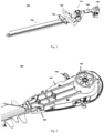
- Fig. 1 is a perspective view of the hedge cutter 100 according to some embodiments of the present invention.
- the hedge cutter 100 comprises a casing 110.
- the casing 110 is configured or attached with the front handle 120 and the rear handle 130.
- a control switch may be disposed on either or both of the front handle 120 and the rear handle 130.
- the front handle 120 is an annular handle formed at or attached to the front of the casing 110.
- the rear handle 130 is formed at the rear of the casing 110.
- the motor is disposed in the casing 110 between the front handle 120 and the rear handle 130.
- the rear handle 130 ends at an expanded end portion and the end portion is used for attaching a detachable battery 140.
- the casing 110 further comprises a baffle 150 at the front of the front handle 120, and the baffle is used to prevent cut branches or leaves from damaging the user and block scraps which may fly to the user during a pruning operation.
- the hedge cutter 100 further comprises a blade assembly 160 extending forward from the casing 110.
- Figs. 2 to 5 further show the structure of the blade assembly 160.
- Fig. 2 shows the mounting portion of the blade assembly 160.
- the mounting portion of the blade assembly 160 comprises an upper casing 161, and the upper casing 161 is mounted to a lower casing 162.
- the upper casing 161 and the lower casing 162 together form a casing structure accommodating the blade structure.
- the casing structure formed by the upper casing 161 and the lower casing 162 is accommodated in the casing 110.
- the lower casing 162 forms a part of the casing 110.
- a gear chamber 164 is formed on the upper casing 161 and is used for mounting a gear train. The gear train is used to transmit the output of the motor to the blade assembly 160. The transmission will be further explained below.
- Amounting portion 163 is alternatively formed on the upper casing 161 and is used for mounting the front handle 120.
- Fig. 3 is an enlarged view of the mounting portion 163.
- a wiring harness structure for example, an opening 1630, is alternatively provided on the mounting portion 163 and is used for a control line to pass through and at least partially fixes the control line.
- the control line may be a wire from the control circuit board to the control switch in the front handle 120.
- the opening 1630 is also used for a bolt (not shown) to pass through to fix the front handle 120 to the mounting portion 163. The bolt further fixes the control line.
- Fig. 4 shows the cutting portion of the blade assembly 160.
- the cutting portion of the blade assembly 160 comprises a first blade 165 and a second blade 166 stacked together.
- the first blade 165 and the second blade 166 may have roughly the same configuration, but they are stacked in opposite directions.
- Fig. 5 shows one blade.
- Sharp teeth 167 are provided on one side of the blade, the sharp teeth 167 transversely extend a short distance and have a flat end, and sharp cutting edges are formed on the two sides of a plane of the teeth. Therefore, the sharp teeth 167 provide a high cutting ability.
- the front teeth and the rear teeth have different configurations.
- Short blunt teeth 168 are provided at the front of the other side.
- the short blunt teeth 168 transversely extend a short distance and have a flat end but no sharp cutting edges on the two sides. Therefore, the short blunt teeth 168 themselves provide no cutting ability, but the length of the short blunt teeth does not prevent objects (for example, hedges) from entering the cutting gap between teeth.
- Long blunt teeth 169 are provided at the rear of the other side. The long blunt teeth 169 transversely extend a long distance and have a smooth end but no sharp cutting edges on the two sides. Therefore, the long blunt teeth 169 themselves provide no cutting ability, and help to prevent objects (for example, hand) from entering the cutting gap between teeth.
- the size of long blunt teeth 169 is larger than the size of short blunt teeth 168. Therefore, long blunt teeth 169 are firmer to cut thick hedges.
- Long blunt teeth 169 and short blunt teeth 168 respectively occupy half the distance of the blade. In the embodiment shown in Fig. 1 , the long blunt teeth 169 occupy about two thirds of the distance of the blade and short blunt teeth 168 occupy about one third of the distance of the blade.
- the blade assembly 160 has a first cutting gap defined by the sharp teeth 167 and the short blunt teeth 168.
- the first cutting gap varies as the first blade 165 and the second blade 166 reciprocate oppositely.
- the short blunt teeth 168 may be changed to sharp teeth 167.
- the blade assembly 160 has a second cutting gap defined by sharp teeth 167 and long blunt teeth 169 at the rear.
- the second cutting gap varies as the first blade 165 and the second blade 166 reciprocate oppositely.
- the long blunt teeth 169 prevent hedges from entering the second cutting gap, but such a configuration can also help to prevent the limbs of the user from entering the second cutting gap. Thus, a higher safety is provided. Since this position is closer to the user, the situation more easily happens that the limbs (especially, hands) of the user approach the blade assembly 160.
- the configuration of the blade assembly of the present invention realizes a good cutting effect.
- a good cutting effect is realized especially in the embodiment where the short blunt teeth 168 are changed to sharp teeth 167.
- the configurations of the motor and the transmission gear train can be adjusted accordingly in the present invention so that the size of the hedge cutter 100 of the present invention can be reduced to keep the hedge cutter more compact and lighter. This will be discussed in detail below.
- Fig. 2 shows the gear chamber 164 accommodating the transmission gear train.
- Fig. 6 shows the in-line arranged gear train 180 according to some embodiments of the present invention.
- the in-line arranged gear train 180 has double layers of planetary gear systems arranged along an axis. Specifically, double layers of planetary gear systems each have gear rings 181 and 182, a sun gear 184 and at least one planetary gear 183.
- the output shaft of the double layers of planetary gear systems is connected to an eccentric mechanism 185.
- the eccentric mechanism 185 drives the first blade 165 and the second blade 166 to reciprocate linearly and oppositely.
- the double layers of planetary gear systems can be replaced a single layer of planetary gear system.
- the size and weight of the hedge cutter 100 of the present invention are further reduced.
- the gear transmission mechanism comprises a planetary gear and a bevel gear. That is to say, the present invention covers any transmission mechanism that can transmit the rotary output of the driving motor to the eccentric mechanism and then convert the rotary movement to a linearly reciprocating movement through the interactions of the eccentric mechanism with the blades.
- Fig. 7 is a partial view of the hedge cutter 100 of the present invention, wherein a part of the casing 110 is removed so as to clearly show some components.
- the motor 170 is shown in Fig. 7 and is arranged in line together with the gear train 180 in the gear chamber 164.
- the casing 110 comprises a projection portion 111 at the top in some embodiments, and the inner space of the projection portion 111 is used for accommodating at least a part of the motor. Few layers of the gear train 180 of the hedge cutter 100 of the present invention and the projection portion 111 of the casing make possible the in-line arrangement of the motor 170 and the gear train 180. The in-line arrangement reduces the length of the hedge cutter 100, and thus reduces the volume and weight of the product.
- the in-line arrangement further enables the motor 170 and the gear train 180 of the hedge cutter 100 to successively approach the rear handle 130 as much as possible.
- the position of the barycenter is changed.
- a safety switch or activation switch can be disposed on the projection portion 111.
- Fig. 8 shows that the casing 110 comprises at least a first air inlet 112.
- the first air inlet 112 is located at the bottom of the casing 110.
- the first air inlet 112 is formed by a plurality of small holes arranged roughly in the shape of a sector. Preferably, these small holes face downward to prevent dust from entering the casing 110.
- the casing 110 further comprises a second air inlet 113.
- the second air inlet 113 is located on the two sides of the casing. As shown in Figs. 7 and 8 , the second air inlet 113 is roughly located at the same height as the air inlet 172 of the motor 170 and the heat radiator 173.
- the heat radiator 173 is disposed close to the control circuit (not shown) to help the control circuit to dissipate heat.
- Air going from the first air inlet 112 into the casing 110 cools the gear train 180, and air going from the second air inlet 113 into the casing 110 accelerates the heat dissipation of the heat radiator and the control circuit.
- a fan 171 is mounted at the bottom of the motor 170. The fan 171 produces a pressure difference for air circulation.
- a first air outlet 114 is provided on the two sides of the top 111 of the casing 110. Air leaving the bottom of the motor 170 leaves the casing 110 through the first air outlet 114.
- the above-mentioned cooling path achieves a good cooling effect on the motor and the control circuit.
- Fig. 9 shows the hedge cutter 100 of the present invention.
- P represents a plane perpendicular to the plane where the blade assembly is located, namely, the paper in Fig. 9 .
- PI, P2 and P3 represent the planes defined when the corresponding dashed lines extend in a direction perpendicular to the plane P.
- P1 is a horizontal plane, namely, the plane perpendicular to the direction of gravity.
- the middle hedge cutter 100 shows the situation when the hedge cutter is placed on the ground, wherein the plane where the blades are located is parallel to the plane P1.
- the upper and lower hedge cutters 100 show the situations where the hedge cutter 100 is suspended from the position of the front handle 120 in the vertical direction. The situations where the user holds the hedge cutter 100 during normal operations are simulated.
- the plane where the blade assembly 160 is located may be the plane P2 or the plane P3.
- the angle between the plane P1 and the plane P2 is A
- the angle between the plane P3 and the plane P1 is B.
- the blade assembly 160, the motor 170, the gear train 180 and the battery are all relatively heavy components.
- the position of the barycenter of the machine is adjusted by adjusting the in-line arranged motor 170 and gear train assembly and other aspects so that the projection position of the barycenter on the plane P is roughly located within the projection range of the front handle 120 on the plane P, and thus a better human-machine interaction effect is achieved.
- the angle A is kept between 0° and 10°, preferably between 0° and 7°, more preferably between 0° and 5°, and the most preferably between 0° and 3°; or the angle B is kept between -10° and 0°, preferably between -7° and 0°, more preferably between -5° and 0°, and the most preferably between -3° and 0°.
- the front handle 120 can be adjusted around the axis horizontal to the longitudinal axis of the hedge cutter (namely in a direction perpendicular to the paper in Fig. 9 ).
- the front handle 120 can rotate around the rotation axis to a desired angle, and then can be fixed by a locking mechanism (not shown). This better helps the user to adjust the position (namely, the angle relative to the casing) of the front handle to change the barycenter of the hedge cutter, thus adapting to the habits of the user. This is more favorable for the hedge cutter having different weights of a battery pack.
- the rear handle 130 can rotate around the longitudinal axis of the hedge cutter relative to the front of the casing 110.
- the hedge cutter further comprises a rotary component at least partially disposed on the casing 110 or the rear handle 130 so that the rear handle 130 and/or a part of the casing 110 comprising the rear handle 130 can rotate around the longitudinal axis of the hedge cutter relative to the other parts of the casing 110 (preferably, the parts accommodating the driving motor 170 and the gear train 180).
- the rear handle 130 is kept static, the orientation of the cutting plane can be changed by holding the front handle 120. This helps to keep the barycenter of the hedge cutter within a vertical plane.
- Fig. 10 is a perspective view of the integrated driving unit 190 according to some embodiments of the present invention.
- the integrated driving unit 190 comprises a motor and a printed circuit board assembly 191 mounted at one end (for example, front end or rear end) of the motor.
- the shape of the printed circuit board assembly 191 may correspond to the cross-section of the driving motor. Therefore, the printed circuit board assembly 191 and the driving motor may be assembled or integrated together in the form of shape to reduce the height and width of the integrated driving unit 190 (thus, the height and width of the hedge cutter are reduced).
- the printed circuit board assembly 191 may be used to realize various control functions of the hedge cutter 100.
- the shown integrated driving unit 190 may further comprise additional printed circuit board assemblies 192 and 193, if necessary.
- the printed circuit board assembly 193 may be arranged in line and in parallel together with the printed circuit board assembly 191, the motor, the motor fan and the transmission mechanism, that is to say, the printed circuit board assembly 193 may be parallel to the rough axis of the in-line arrangement of the printed circuit board 191, the motor, the motor fan and the transmission mechanism and may be attached to the in-line arrangement in contact fit, and the printed circuit board assembly 192 may be integrated with the in-line arrangement at a tilt angle.
- each printed circuit board assembly 191, 192 or 193 may be tightly attached to the heat radiator and integrated with the in-line arrangement.
- the printed circuit board assemblies may be mounted at one end/side of the driving motor by use of any mounting/attachment means, for example, bolts, fasteners and mounting brackets.
- a heat radiator may be disposed between the printed circuit board assembly 191 and the driving motor to improve the heat dissipation efficiency.
- the size of the hedge cutter in each dimension may be reduced by adopting the integration of the printed circuit board assembly in the rough axis direction of the in-line arrangement and the integration in the direction perpendicular to the rough axis direction.
- the adoption of the in-line arrangement provides the ability of integrating the printed circuit board assemblies in each dimension. Therefore, a compact and miniature casing and product design can be realized only by partially accommodating/adapting to the in-line arranged casing.
- Fig. 11 is a perspective view of the integrated driving unit 200 according to some embodiments of the present invention.
- the integrated driving unit 200 comprises a printed circuit board assembly 210, a first mounting bracket 220, a motor 170 and a second mounting bracket 230 in turn from the top down.
- the printed circuit board assembly 210 is mounted on the motor 170 through the first mounting bracket 220, and the motor 170 is mounted on the casing 110 of the hedge cutter 100 through the second mounting bracket 230.
- the motor 170 is further connected to the gear train 180.
- the printed circuit board assembly 210, the first mounting bracket 220, the motor 170 and the second mounting bracket 230 have cross-sections whose sizes are basically the same.
- the integrated driving unit 200 further comprises a heat dissipation device 240.
- the heat dissipation device 240 is formed by a plurality of metal sheets radiating outwards from the center of a circle and separated from each other.
- the metal sheets may be selected from heat-conductive metals, for example, aluminum or aluminum alloy. It may be understood that heat radiators in other forms may be applicable to the present invention.
- the heat dissipation device is located between the motor 170 and the printed circuit board assembly 210.
- the heat dissipation device 240 is preferably a part of the first mounting bracket 220 so that the heat dissipation device can help the printed circuit board assembly 210 to dissipate heat.
- the heat dissipation device 240 faces the bottom of the motor 170.
- a fan 250 is connected to the output shaft of the motor 170.
- the rotations of the motor 170 enable the fan 250 to rotate. Air flows through the inside of the motor, leaves the motor from the bottom of the motor, is blown to the heat dissipation device 240, and then leaves the hedge cutter from the air duct or air outlet on the casing 110 of the hedge cutter 100. Thus, heat is taken away from the motor and the heat dissipation device.
- the technical solution of the present invention improves the heat dissipation effect on the components, thus improving the performance of the hedge cutter and prolonging the service life of the hedge cutter.
Landscapes
- Life Sciences & Earth Sciences (AREA)
- Biodiversity & Conservation Biology (AREA)
- Ecology (AREA)
- Forests & Forestry (AREA)
- Environmental Sciences (AREA)
- Harvester Elements (AREA)
Abstract
Description
- The present invention relates to an outdoor garden instrument, in particular to a hedge cutter for pruning branches or leaves of hedges, or a hedge cutter wherein the cutting blade is driven by a motor to reciprocate.
- The hedge cutter is an outdoor garden instrument used to cut branches or leaves by means of a linearly reciprocating long and thin cutting blade or cutting rod so that hedges can be formed as expected. The cutting work is usually done in the following way: The worker holds a hedge cutter with two hands and moves the cutting blade along the shape of a hedge. Currently, electric hedge cutters are very popular. Since electric hedge cutters are held with two hands and are moved during operations, they are lighter and more compact than diesel hedge cutters. In order to thoroughly and stably cut hedges, the rotary driving force output from the motor on a hedge cutter is usually converted by, for example, a gear reduction mechanism, into a larger torque and a lower speed.
- However, conventional electric hedge cutters are usually still heavy and difficult for common users to operate. Portable and easy-to-operate hedge cutters are still required in the art.
- In view of the above-mentioned background, the object of the present invention is to provide an alternative electric garden instrument, in particular a hedge cutter, which eliminates or alleviates the above-mentioned technical problem or at least provides an available choice.
- Those skilled in the art will obtain other objects of the present invention from the description below. Therefore, the statement of the above-mentioned object is not finite and is only used to describe some of a lot of objectives of the present invention.
- Therefore, one aspect of the present invention is a hedge cutter. The hedge cutter comprises a driving motor disposed in a casing, a transmission mechanism disposed in the casing and coupled with the driving motor, a blade arrangement extending from the casing and coupled with the transmission mechanism, and a printed circuit board assembly disposed in the casing and mounted at one end of the driving motor, wherein the shape of the printed circuit board assembly corresponds to the cross-section of the driving motor, and wherein the in-line arrangement of the driving motor and the printed circuit board assembly is perpendicular to the longitudinal axis of the blade arrangement.
- In one embodiment, the present invention provides an electric garden instrument and the electric garden instrument comprises a driving motor assembly disposed in the casing, a transmission mechanism disposed in the casing and coupled with the driving motor assembly, a blade arrangement extending from the casing and coupled with the transmission mechanism, and a printed circuit board assembly mounted on the driving motor assembly, wherein a heat radiator is disposed between the driving motor assembly and the printed circuit board assembly.
- In one embodiment, the printed circuit board assembly comprises a first printed circuit board, which is mounted at one end of the driving motor assembly away from the output shaft of the motor, and the heat radiator comprises a first heat radiator, which is disposed between the driving motor assembly and the first printed circuit board.
- In one embodiment, the shape of the first printed circuit board corresponds to the shape of the cross-section of the driving motor assembly.
- In one embodiment, the ratio of the area of the first printed circuit board to the cross-sectional area of the driving motor assembly is 0.7 to 1.5.
- In one embodiment, the driving motor assembly, the first printed circuit board and the first heat radiator are arranged in line, and the first printed circuit board is positioned roughly parallel to the extension direction of the blade arrangement.
- In one embodiment, the first heat radiator is a passive heat radiator and covers at least 50% of the area of the first printed circuit board.
- In one embodiment, the printed circuit board assembly further comprises a second printed circuit board, and the second printed circuit board is mounted on a side of the driving motor assembly and is positioned perpendicular to the extension direction of the blade arrangement.
- In one embodiment, a second heat radiator is disposed between the driving motor assembly and the second printed circuit board.
- In one embodiment, the second heat radiator is a passive heat radiator and serves as a support of the second printed circuit board, and the second printed circuit board is at least partially accommodated in the second heat radiator.
- In one embodiment, the printed circuit board assembly further comprises a third printed circuit board, and the third printed circuit board is mounted on a side of the driving motor assembly and is positioned to form an angle with the extension direction of the blade arrangement. The angle is in a range of 30° to 70°.
- In one embodiment, a third heat radiator is disposed between the driving motor assembly and the third printed circuit board. In one embodiment, the third heat radiator is a passive heat radiator and serves as a support of the third printed circuit board, and the third printed circuit board is at least partially accommodated in the third heat radiator.
- In one embodiment, the driving motor assembly comprises a fan, the fan is arranged at one end of the driving motor assembly close to the output shaft of the motor, and is in the same in-line arrangement as the driving motor and the first printed circuit board.
- In one embodiment, the transmission mechanism comprises a gear transmission mechanism, a belt transmission mechanism or a combination of the gear transmission mechanism and the belt transmission mechanism. Wherein, the transmission mechanism is a gear transmission mechanism, and the gear transmission mechanism comprises a planetary gear or a bevel gear.
- In one embodiment, the transmission mechanism comprises a planetary gear and a sun gear, and in addition, the transmission mechanism is in the same in-line arrangement as the driving motor assembly and the printed circuit board assembly, wherein the planetary gear comprises one stage of planetary gear or two stages of planetary gears.
- In one embodiment, the casing comprises or is attached with a front handle and a rear handle, a trigger for starting the driving motor assembly is disposed on either of the front handle and the rear handle, a safety switch is disposed on either of the front handle and the rear handle, and the driving motor assembly rotates only when the trigger and the safety switch are both actuated.
- In one embodiment, the rear handle can rotate relative to at least a part of the casing and perpendicular to the longitudinal axis of the blade arrangement.
- In one embodiment, the barycenter of the electric garden instrument is roughly located at the front handle.
- In one embodiment, the power supply of the electric garden instrument is a detachable battery pack, and the detachable battery pack is accommodated in or attached to the casing or attached to the front handle or the rear handle.
- In one embodiment, the blade arrangement comprises at least a cutting rod, and the cutting rod comprises cutting edge teeth arranged on the two sides and having a sharp cutting edge portion, wherein the top of at least some cutting edge teeth close to the casing have a blunt tip.
- In one embodiment, the upper top of the casing has projections suitable for accommodating the in-line arrangement comprising the printed circuit board assembly and the driving motor assembly.
- In one embodiment, an exhaust port is disposed on the top of the casing to promote air circulation and improve the heat dissipation performance.
- The electric garden instrument may be a hedge cutter.
- More preferably, the rear handle can at least rotate relative to at least a part of the casing and perpendicular to the longitudinal axis of the blade arrangement.
- In one embodiment, the front handle can rotate around the mounting axis so that the angle of the front handle relative to the casing can be adjusted.
- In one embodiment, the rear handle can rotate around the longitudinal axis of the hedge cutter.
- The present invention has many advantages. The in-line integration of the printed circuit board assembly and the driving motor is adopted in the present invention, and in addition, the motor fan and the driving mechanism may be in the same in-line arrangement as the printed circuit board assembly and the driving motor. Therefore, a compact design of the hedge cutter is provided and a light weight of the hedge cutter is enabled. In addition, the in-line arrangement of components makes it easy to put the barycenter of the hedge cutter at the front handle, and thus human-machine interactions are improved. Furthermore, in some preferred embodiments, the combination of the first stage planetary gear and double-sided sharp cutting edge teeth can provide not only a light and compact design, but also a satisfactory cutting/pruning performance.
- From the description of the following exemplified embodiments in combination with the drawings, the above-mentioned characteristics and other characteristics of the present invention will become obvious. In the drawings,
-
Fig. 1 is a perspective view of the overall appearance of the hedge cutter according to some embodiments of the present invention, -
Fig. 2 is a perspective view of the blade assembly of the hedge cutter according to some embodiments of the present invention, -
Fig. 3 is an enlarged partial view of the upper casing of the blade assembly shown inFig. 2 , -
Fig. 4 shows the blade assembly according to some embodiments of the present invention, -
Fig. 5 shows one blade of the blade assembly according to some embodiments of the present invention, -
Fig. 6 shows the gear train according to some embodiments of the present invention, -
Fig. 7 shows internal components in the hedge cutter according to some embodiments of the present invention, -
Fig. 8 shows the exterior of the hedge cutter according to some embodiments of the present invention, -
Fig. 9 shows different orientations of the hedge cutter according to some embodiments of the present invention, -
Fig. 10 also shows an integrated driving unit of the hedge cutter according to some embodiments of the present invention. -
Fig. 11 also shows an integrated driving unit of the hedge cutter according to some embodiments of the present invention. - In the attached claims and the above-mentioned description, unless otherwise required for the reason of an expressional language or in the context brought about by an necessary implication, the term "comprise" or a variant (for example, "contain" or "have") is used inclusively, that is to say, it is used to indicate the existence of the characteristics, but is not used to exclude other characteristics existing or added in various embodiments of the present invention.
- The terms such as "horizontal", "vertical", "transverse", "longitudinal", "upper", "lower" and similar terms used in the document are used to describe the present invention in the directions the present invention is normally used, but not used to restrict the present invention in any specific direction.
- It should be understood that if publications of any prior art are quoted in the document, such references do not constitute the acknowledgement that the publications form a part of common knowledge in the art in any country.
- In the document, the arrangement including the driving motor and the printed circuit board assembly mounted at one end of the driving motor may be called an in-line arrangement. Alternatively, besides the driving motor and the printed circuit board assembly mounted at one end of the driving motor, the arrangement includes the printed circuit board assembly, the heat radiator and/or the motor fan disposed between the driving motor and the printed circuit board assembly. The arrangement including the printed circuit board assembly, heat radiator, driving motor and/or motor fan may also be called an in-line arrangement. The meaning of calling such an arrangement an in-line arrangement lies in that the components (printed circuit board assembly, heat radiator, driving motor and motor fan) in the arrangement are arranged in the axis direction, or arranged opposite to each other roughly in an in-line way (roughly having the same axis or roughly connected in series on the same axis), and thus a compact arrangement is formed. As mentioned below, in some preferred embodiments of the present invention, the transmission mechanism (including the gears) located between the integrated driving unit and the driven component (cutting rod) may also be in the same in-line arrangement as the printed circuit board assembly and the driving motor, and thus the overall structure, shape and size of the hedge cutter are more compact. On the one hand, a compact design enables components to occupy a small space. On the other hand, the compact design requires fewer components and mounting components so that the total weight can be reduced, other layouts can be designed and a layout (which will be described below) can be made by use of the barycenter of the hedge cutter. As further discussed below, the rough axis of an in-line arrangement may be perpendicular to the longitudinal direction of the blade arrangement or the cutting rod, and such an in-line arrangement may be called vertical in-line arrangement in the document.
- The hedge cutter in some embodiments of the present invention will be described below in combination with the drawings.
-
Fig. 1 is a perspective view of thehedge cutter 100 according to some embodiments of the present invention. As shown, thehedge cutter 100 comprises a casing 110.Thecasing 110 is configured or attached with thefront handle 120 and therear handle 130. A control switch may be disposed on either or both of thefront handle 120 and therear handle 130. In some embodiments, thefront handle 120 is an annular handle formed at or attached to the front of thecasing 110. Therear handle 130 is formed at the rear of thecasing 110. The motor is disposed in thecasing 110 between thefront handle 120 and therear handle 130. Therear handle 130 ends at an expanded end portion and the end portion is used for attaching adetachable battery 140. Thecasing 110 further comprises abaffle 150 at the front of thefront handle 120, and the baffle is used to prevent cut branches or leaves from damaging the user and block scraps which may fly to the user during a pruning operation. - The
hedge cutter 100 according to the embodiments of the present invention further comprises ablade assembly 160 extending forward from thecasing 110.Figs. 2 to 5 further show the structure of theblade assembly 160. -
Fig. 2 shows the mounting portion of theblade assembly 160. The mounting portion of theblade assembly 160 comprises anupper casing 161, and theupper casing 161 is mounted to alower casing 162. Theupper casing 161 and thelower casing 162 together form a casing structure accommodating the blade structure. In some embodiments, the casing structure formed by theupper casing 161 and thelower casing 162 is accommodated in thecasing 110. In other embodiments, thelower casing 162 forms a part of thecasing 110. Agear chamber 164 is formed on theupper casing 161 and is used for mounting a gear train. The gear train is used to transmit the output of the motor to theblade assembly 160. The transmission will be further explained below. - Amounting
portion 163 is alternatively formed on theupper casing 161 and is used for mounting thefront handle 120.Fig. 3 is an enlarged view of the mountingportion 163. A wiring harness structure, for example, anopening 1630, is alternatively provided on the mountingportion 163 and is used for a control line to pass through and at least partially fixes the control line. The control line may be a wire from the control circuit board to the control switch in thefront handle 120. In some embodiments, theopening 1630 is also used for a bolt (not shown) to pass through to fix thefront handle 120 to the mountingportion 163. The bolt further fixes the control line. -
Fig. 4 shows the cutting portion of theblade assembly 160. The cutting portion of theblade assembly 160 comprises afirst blade 165 and asecond blade 166 stacked together. In one embodiment, thefirst blade 165 and thesecond blade 166 may have roughly the same configuration, but they are stacked in opposite directions.Fig. 5 shows one blade.Sharp teeth 167 are provided on one side of the blade, thesharp teeth 167 transversely extend a short distance and have a flat end, and sharp cutting edges are formed on the two sides of a plane of the teeth. Therefore, thesharp teeth 167 provide a high cutting ability. On the other side of the blade, the front teeth and the rear teeth have different configurations. Shortblunt teeth 168 are provided at the front of the other side. The shortblunt teeth 168 transversely extend a short distance and have a flat end but no sharp cutting edges on the two sides. Therefore, the shortblunt teeth 168 themselves provide no cutting ability, but the length of the short blunt teeth does not prevent objects (for example, hedges) from entering the cutting gap between teeth. Longblunt teeth 169 are provided at the rear of the other side. The longblunt teeth 169 transversely extend a long distance and have a smooth end but no sharp cutting edges on the two sides. Therefore, the longblunt teeth 169 themselves provide no cutting ability, and help to prevent objects (for example, hand) from entering the cutting gap between teeth. The size of longblunt teeth 169 is larger than the size of shortblunt teeth 168. Therefore, longblunt teeth 169 are firmer to cut thick hedges. Longblunt teeth 169 and shortblunt teeth 168 respectively occupy half the distance of the blade. In the embodiment shown inFig. 1 , the longblunt teeth 169 occupy about two thirds of the distance of the blade and shortblunt teeth 168 occupy about one third of the distance of the blade. - By stacking the
first blade 165 and thesecond blade 166 having the above-mentioned configurations in opposite directions, theblade assembly 160 has a first cutting gap defined by thesharp teeth 167 and the short blunt teeth 168.The first cutting gap varies as thefirst blade 165 and thesecond blade 166 reciprocate oppositely. In some embodiments, in order to improve the cutting effect, the shortblunt teeth 168 may be changed tosharp teeth 167. - The
blade assembly 160 has a second cutting gap defined bysharp teeth 167 and longblunt teeth 169 at the rear. The second cutting gap varies as thefirst blade 165 and thesecond blade 166 reciprocate oppositely. The longblunt teeth 169 prevent hedges from entering the second cutting gap, but such a configuration can also help to prevent the limbs of the user from entering the second cutting gap. Thus, a higher safety is provided. Since this position is closer to the user, the situation more easily happens that the limbs (especially, hands) of the user approach theblade assembly 160. - The configuration of the blade assembly of the present invention realizes a good cutting effect. A good cutting effect is realized especially in the embodiment where the short
blunt teeth 168 are changed tosharp teeth 167. On the basis of this, with the cutting effect guaranteed, the configurations of the motor and the transmission gear train can be adjusted accordingly in the present invention so that the size of thehedge cutter 100 of the present invention can be reduced to keep the hedge cutter more compact and lighter. This will be discussed in detail below. -
Fig. 2 shows thegear chamber 164 accommodating the transmission gear train.Fig. 6 shows the in-line arrangedgear train 180 according to some embodiments of the present invention. In some embodiments, the in-line arrangedgear train 180 has double layers of planetary gear systems arranged along an axis. Specifically, double layers of planetary gear systems each have gear rings 181 and 182, asun gear 184 and at least oneplanetary gear 183. The output shaft of the double layers of planetary gear systems is connected to aneccentric mechanism 185. Theeccentric mechanism 185 drives thefirst blade 165 and thesecond blade 166 to reciprocate linearly and oppositely. In some embodiments, especially in the embodiments where the shortblunt teeth 168 are changed tosharp teeth 167, the double layers of planetary gear systems can be replaced a single layer of planetary gear system. Thus, the size and weight of thehedge cutter 100 of the present invention are further reduced. In addition, although the arrangements of double layers of planetary gears (two stages of planetary gears) and a single layer of planetary gear (one stage of planetary gear) are stated in the previous description, it is easily understood that the present invention is not limited to such arrangements. Various transmission mechanisms can be adopted for the present invention. The gear transmission mechanism comprises a planetary gear and a bevel gear. That is to say, the present invention covers any transmission mechanism that can transmit the rotary output of the driving motor to the eccentric mechanism and then convert the rotary movement to a linearly reciprocating movement through the interactions of the eccentric mechanism with the blades. -
Fig. 7 is a partial view of thehedge cutter 100 of the present invention, wherein a part of thecasing 110 is removed so as to clearly show some components. Themotor 170 is shown inFig. 7 and is arranged in line together with thegear train 180 in thegear chamber 164. As shown inFig. 8 , thecasing 110 comprises aprojection portion 111 at the top in some embodiments, and the inner space of theprojection portion 111 is used for accommodating at least a part of the motor. Few layers of thegear train 180 of thehedge cutter 100 of the present invention and theprojection portion 111 of the casing make possible the in-line arrangement of themotor 170 and thegear train 180. The in-line arrangement reduces the length of thehedge cutter 100, and thus reduces the volume and weight of the product. On the other hand, the in-line arrangement further enables themotor 170 and thegear train 180 of thehedge cutter 100 to successively approach therear handle 130 as much as possible. Thus, the position of the barycenter is changed. The change of the barycenter will be further discussed below. Favorably, a safety switch or activation switch can be disposed on theprojection portion 111. -
Fig. 8 shows that thecasing 110 comprises at least afirst air inlet 112. Thefirst air inlet 112 is located at the bottom of thecasing 110. In one embodiment, thefirst air inlet 112 is formed by a plurality of small holes arranged roughly in the shape of a sector. Preferably, these small holes face downward to prevent dust from entering thecasing 110. Thecasing 110 further comprises asecond air inlet 113. Thesecond air inlet 113 is located on the two sides of the casing. As shown inFigs. 7 and8 , thesecond air inlet 113 is roughly located at the same height as theair inlet 172 of themotor 170 and theheat radiator 173. Theheat radiator 173 is disposed close to the control circuit (not shown) to help the control circuit to dissipate heat. Thus, air going from thefirst air inlet 112 into thecasing 110 cools thegear train 180, and air going from thesecond air inlet 113 into thecasing 110 accelerates the heat dissipation of the heat radiator and the control circuit. Air goes from theair inlet 172 in the motor casing into themotor 170 to cool themotor 170. Then air leaves themotor 170 through the bottom of themotor 170. Afan 171 is mounted at the bottom of themotor 170. Thefan 171 produces a pressure difference for air circulation. Afirst air outlet 114 is provided on the two sides of the top 111 of thecasing 110. Air leaving the bottom of themotor 170 leaves thecasing 110 through thefirst air outlet 114. The above-mentioned cooling path achieves a good cooling effect on the motor and the control circuit. -
Fig. 9 shows thehedge cutter 100 of the present invention. P represents a plane perpendicular to the plane where the blade assembly is located, namely, the paper inFig. 9 . PI, P2 and P3 represent the planes defined when the corresponding dashed lines extend in a direction perpendicular to the plane P. Wherein P1 is a horizontal plane, namely, the plane perpendicular to the direction of gravity. Themiddle hedge cutter 100 shows the situation when the hedge cutter is placed on the ground, wherein the plane where the blades are located is parallel to the plane P1. The upper andlower hedge cutters 100 show the situations where thehedge cutter 100 is suspended from the position of thefront handle 120 in the vertical direction. The situations where the user holds thehedge cutter 100 during normal operations are simulated. In this case, the plane where theblade assembly 160 is located may be the plane P2 or the plane P3. The angle between the plane P1 and the plane P2 is A, and the angle between the plane P3 and the plane P1 is B. For thehedge cutter 100, theblade assembly 160, themotor 170, thegear train 180 and the battery are all relatively heavy components. As mentioned above, the position of the barycenter of the machine is adjusted by adjusting the in-line arrangedmotor 170 and gear train assembly and other aspects so that the projection position of the barycenter on the plane P is roughly located within the projection range of thefront handle 120 on the plane P, and thus a better human-machine interaction effect is achieved. - To be more specific, it is sometimes necessary to frequently change the gesture of the body or arms to rotate the machine so as to change the service state of the machine during pruning operations. This not only increases the work intensity, but also hardly meets the pruning requirements in practice. In addition, the whole machine is poorly balanced if it is used in this way. For example, when a side of a hedge needs to be pruned, it is necessary to place the hedge cutter horizontally. When the hedge cutter used horizontally is compared with the hedge cutter used normally, the barycenter of the whole machine changes greatly relative to the position of the front handle, and the barycenter relative to the handle is located on a horizontal direction. Thus, the user will feel that the machine gets heavier, a great discomfort will be brought about to the arms, and the comfort of the user will be influenced when the user operates the machine. Such a problem will become more prominent especially when the capacity of the battery pack of the hedge cutter is large. Such a problem is solved by adjusting the position of the barycenter in the present invention. As shown in
Fig. 9 , the angle A is kept between 0° and 10°, preferably between 0° and 7°, more preferably between 0° and 5°, and the most preferably between 0° and 3°; or the angle B is kept between -10° and 0°, preferably between -7° and 0°, more preferably between -5° and 0°, and the most preferably between -3° and 0°. - In one embodiment, the
front handle 120 can be adjusted around the axis horizontal to the longitudinal axis of the hedge cutter (namely in a direction perpendicular to the paper inFig. 9 ). To be specific, thefront handle 120 can rotate around the rotation axis to a desired angle, and then can be fixed by a locking mechanism (not shown). This better helps the user to adjust the position (namely, the angle relative to the casing) of the front handle to change the barycenter of the hedge cutter, thus adapting to the habits of the user. This is more favorable for the hedge cutter having different weights of a battery pack. - In other embodiments of the present invention, the
rear handle 130 can rotate around the longitudinal axis of the hedge cutter relative to the front of thecasing 110. In these embodiments, the hedge cutter further comprises a rotary component at least partially disposed on thecasing 110 or therear handle 130 so that therear handle 130 and/or a part of thecasing 110 comprising therear handle 130 can rotate around the longitudinal axis of the hedge cutter relative to the other parts of the casing 110 (preferably, the parts accommodating the drivingmotor 170 and the gear train 180). Thus, when therear handle 130 is kept static, the orientation of the cutting plane can be changed by holding thefront handle 120. This helps to keep the barycenter of the hedge cutter within a vertical plane. -
Fig. 10 is a perspective view of theintegrated driving unit 190 according to some embodiments of the present invention. Theintegrated driving unit 190 comprises a motor and a printedcircuit board assembly 191 mounted at one end (for example, front end or rear end) of the motor. The shape of the printedcircuit board assembly 191 may correspond to the cross-section of the driving motor. Therefore, the printedcircuit board assembly 191 and the driving motor may be assembled or integrated together in the form of shape to reduce the height and width of the integrated driving unit 190 (thus, the height and width of the hedge cutter are reduced). The printedcircuit board assembly 191 may be used to realize various control functions of thehedge cutter 100. In some embodiments, besides the printedcircuit board assembly 191 mounted at one end of the driving motor, the shownintegrated driving unit 190 may further comprise additional printedcircuit board assemblies circuit board assembly 193 may be arranged in line and in parallel together with the printedcircuit board assembly 191, the motor, the motor fan and the transmission mechanism, that is to say, the printedcircuit board assembly 193 may be parallel to the rough axis of the in-line arrangement of the printedcircuit board 191, the motor, the motor fan and the transmission mechanism and may be attached to the in-line arrangement in contact fit, and the printedcircuit board assembly 192 may be integrated with the in-line arrangement at a tilt angle. In the embodiments where such a configuration is adopted, besides the dimensional integration in the rough axis direction of the in-line arrangement, the integration in the direction/dimension perpendicular to the rough axis direction is realized. Thus, the height and width of the hedge cutter are reduced. It should be understood that the additional printedcircuit board assemblies circuit board assemblies circuit board assembly 191. In addition, each printedcircuit board assembly circuit board assembly 191 and the driving motor to improve the heat dissipation efficiency. In various embodiments of the present invention, the size of the hedge cutter in each dimension may be reduced by adopting the integration of the printed circuit board assembly in the rough axis direction of the in-line arrangement and the integration in the direction perpendicular to the rough axis direction. The adoption of the in-line arrangement provides the ability of integrating the printed circuit board assemblies in each dimension. Therefore, a compact and miniature casing and product design can be realized only by partially accommodating/adapting to the in-line arranged casing. -
Fig. 11 is a perspective view of theintegrated driving unit 200 according to some embodiments of the present invention. Theintegrated driving unit 200 comprises a printedcircuit board assembly 210, afirst mounting bracket 220, amotor 170 and asecond mounting bracket 230 in turn from the top down. The printedcircuit board assembly 210 is mounted on themotor 170 through thefirst mounting bracket 220, and themotor 170 is mounted on thecasing 110 of thehedge cutter 100 through thesecond mounting bracket 230. Themotor 170 is further connected to thegear train 180. Wherein, the printedcircuit board assembly 210, thefirst mounting bracket 220, themotor 170 and thesecond mounting bracket 230 have cross-sections whose sizes are basically the same. - In some embodiments, the
integrated driving unit 200 further comprises aheat dissipation device 240. In one embodiment, theheat dissipation device 240 is formed by a plurality of metal sheets radiating outwards from the center of a circle and separated from each other. The metal sheets may be selected from heat-conductive metals, for example, aluminum or aluminum alloy. It may be understood that heat radiators in other forms may be applicable to the present invention. The heat dissipation device is located between themotor 170 and the printedcircuit board assembly 210. Theheat dissipation device 240 is preferably a part of thefirst mounting bracket 220 so that the heat dissipation device can help the printedcircuit board assembly 210 to dissipate heat. Theheat dissipation device 240 faces the bottom of themotor 170. - In some embodiments, a
fan 250 is connected to the output shaft of themotor 170. When the motor works, the rotations of themotor 170 enable thefan 250 to rotate. Air flows through the inside of the motor, leaves the motor from the bottom of the motor, is blown to theheat dissipation device 240, and then leaves the hedge cutter from the air duct or air outlet on thecasing 110 of thehedge cutter 100. Thus, heat is taken away from the motor and the heat dissipation device. Through the heat radiator disposed between the motor and the printed circuit board assembly, the technical solution of the present invention improves the heat dissipation effect on the components, thus improving the performance of the hedge cutter and prolonging the service life of the hedge cutter. - The present invention is described in detail in combination with the drawings. However, the embodiments should be considered illustrative, but not restrictive. It should be understood that only exemplary embodiments are shown and described and they do not restrict the present invention in any way. It may be understood that any characteristic described in the document can be applied to any embodiment. Illustrative embodiments do not exclude each other or exclude other embodiments not given in the document. Therefore, the present invention further provides a combination of one or more of the above-mentioned exemplary embodiments. Modifications and changes can be made to the present invention without departing from the spirit and scope of the present invention. Therefore, only restrictions indicated by the attached claims should be made.
Claims (15)
- A hedge cutter, comprising:a casing, the casing comprising a front handle and a rear handle,a driving assembly located in the casing,a transmission assembly located in the casing and coupled with the driving assembly, anda blade assembly coupled with the transmission assembly, the blade assembly defining the plane of the blade assembly,wherein, when the hedge cutter is suspended from the front handle, the angle between the plane of the blade assembly and the horizontal plane is between -7° and 7°, preferably between -5° and 5°, and more preferably between 3° and 3°.
- The hedge cutter as claimed in claim 1, wherein the blade assembly comprises at least one blade, and the blade comprises sharp teeth on one side and blunt teeth on the other side.
- The hedge cutter as claimed in claim 2, wherein the other side comprises short blunt teeth at the front and long blunt teeth at the rear.
- The hedge cutter as claimed in claim 1, wherein the transmission assembly is an in-line gear train and the in-line gear train comprises one or more planetary gear trains, and one or more planetary gear trains are arranged in line along an axis.
- The hedge cutter as claimed in claim 4, wherein the driving assembly comprises a motor, and the motor and the in-line gear train are arranged in line along the axis.
- The hedge cutter as claimed in claim 5, wherein the top of the casing has a projection portion and the projection portion is used to accommodate at least a part of the driving assembly.
- The hedge cutter as claimed in claim 1, wherein the casing a first vent located at the bottom or side of the casing and a second vent located at the top of the casing.
- The hedge cutter as claimed in claim 7, wherein the first vent comprises a first air inlet located at the bottom of the casing, and the first air inlet faces the driving assembly.
- The hedge cutter as claimed in claim 7, wherein the first vent comprises a second air inlet located at the side of the casing, and the second air inlet faces a heat dissipation device in the casing and/or a vent in the driving assembly.
- The hedge cutter as claimed in claim 7, wherein the second vent faces a fan in the driving assembly.
- The hedge cutter as claimed in claim 1, wherein the driving assembly comprises a motor and a first control circuit board located at the top of the motor, and the motor and the first control circuit board have a similar cross-section shape.
- The hedge cutter as claimed in claim 11, wherein the motor fan, motor and first control circuit board are in the same in-line arrangement.
- The hedge cutter as claimed in claim 9, wherein the heat dissipation device is located on one side of the driving assembly, and a second control circuit board is thermally connected to the heat dissipation device.
- The hedge cutter as claimed in any of claims 1 to 13, wherein the front handle can rotate around the mounting axis so as to regulate the angle of the front handle relative to the casing.
- The hedge cutter as claimed in any of claims 1 to 13, wherein the rear handle can rotate around the longitudinal axis of the hedge cutter.
Applications Claiming Priority (1)
| Application Number | Priority Date | Filing Date | Title |
|---|---|---|---|
| CN202010794533.7A CN114051850B (en) | 2020-08-10 | 2020-08-10 | hedge trimmer |
Publications (3)
| Publication Number | Publication Date |
|---|---|
| EP3954198A1 true EP3954198A1 (en) | 2022-02-16 |
| EP3954198B1 EP3954198B1 (en) | 2026-03-11 |
| EP3954198C0 EP3954198C0 (en) | 2026-03-11 |
Family
ID=77207058
Family Applications (1)
| Application Number | Title | Priority Date | Filing Date |
|---|---|---|---|
| EP21189526.3A Active EP3954198B1 (en) | 2020-08-10 | 2021-08-03 | Hedge cutter |
Country Status (3)
| Country | Link |
|---|---|
| EP (1) | EP3954198B1 (en) |
| CN (1) | CN114051850B (en) |
| AU (1) | AU2021104481A4 (en) |
Cited By (2)
| Publication number | Priority date | Publication date | Assignee | Title |
|---|---|---|---|---|
| CN113875425A (en) * | 2021-11-10 | 2022-01-04 | 陈春英 | Gardens are pruned and are used gardens saw |
| DE102024115954B3 (en) | 2024-06-07 | 2025-05-22 | Andreas Stihl Ag & Co. Kg | Tool drive unit for a cutting blade of a hand-held tool, and hand-held tool with the tool drive unit |
Families Citing this family (4)
| Publication number | Priority date | Publication date | Assignee | Title |
|---|---|---|---|---|
| JP2024128873A (en) * | 2023-03-10 | 2024-09-24 | 株式会社やまびこ | Electric work machine |
| CN119366365A (en) * | 2023-07-26 | 2025-01-28 | 南京泉峰科技有限公司 | Pruning Machine |
| CN119856649B (en) * | 2025-03-03 | 2025-09-12 | 浙江天泰机械有限公司 | Hedge trimmer |
| CN120355735B (en) * | 2025-06-23 | 2025-09-02 | 浙江德硕科技股份有限公司 | Intelligent centering method and system for hedge trimmer |
Citations (7)
| Publication number | Priority date | Publication date | Assignee | Title |
|---|---|---|---|---|
| EP1782682A2 (en) * | 2005-11-07 | 2007-05-09 | GARDENA Manufacturing GmbH | Manually operated working device |
| WO2008029255A2 (en) * | 2006-09-05 | 2008-03-13 | Senson Investments Limited | Hand-held power tool |
| EP2223781A2 (en) * | 2009-02-27 | 2010-09-01 | Andreas Stihl AG & Co. KG | Battery-operated, hand-held work device |
| DE202013104882U1 (en) * | 2012-10-31 | 2014-02-18 | Hitachi Koki Co., Ltd. | Portable tool |
| US20170071134A1 (en) * | 2015-09-15 | 2017-03-16 | Chervon (Hk) Limited | Hedge trimmer |
| CN207505508U (en) * | 2017-09-30 | 2018-06-19 | 南京德朔实业有限公司 | Pruner |
| US20190239446A1 (en) * | 2018-02-05 | 2019-08-08 | Makita Corporation | Hedge trimmer |
Family Cites Families (6)
| Publication number | Priority date | Publication date | Assignee | Title |
|---|---|---|---|---|
| US3859776A (en) * | 1973-01-08 | 1975-01-14 | Weed Eaters Inc | Rotary cutting assembly |
| US4286675A (en) * | 1979-06-25 | 1981-09-01 | Beaird-Poulan Division Of Emerson Electric Co. | Narrow profile power handle for line trimmer and the like |
| DE102006018072B4 (en) * | 2006-04-10 | 2016-08-11 | Andreas Stihl Ag & Co. Kg | hedge clippers |
| CN103004485B (en) * | 2011-09-21 | 2015-03-11 | 苏州宝时得电动工具有限公司 | Pruning shears and garden tool |
| DE102012007405B4 (en) * | 2012-04-16 | 2017-02-09 | Andreas Stihl Ag & Co. Kg | implement |
| US10461610B2 (en) * | 2016-06-03 | 2019-10-29 | Molon Motor & Coil Corporation | Electrically-conductive connection device for use in a compact miniaturized motor assembly |
-
2020
- 2020-08-10 CN CN202010794533.7A patent/CN114051850B/en active Active
-
2021
- 2021-07-23 AU AU2021104481A patent/AU2021104481A4/en active Active
- 2021-08-03 EP EP21189526.3A patent/EP3954198B1/en active Active
Patent Citations (7)
| Publication number | Priority date | Publication date | Assignee | Title |
|---|---|---|---|---|
| EP1782682A2 (en) * | 2005-11-07 | 2007-05-09 | GARDENA Manufacturing GmbH | Manually operated working device |
| WO2008029255A2 (en) * | 2006-09-05 | 2008-03-13 | Senson Investments Limited | Hand-held power tool |
| EP2223781A2 (en) * | 2009-02-27 | 2010-09-01 | Andreas Stihl AG & Co. KG | Battery-operated, hand-held work device |
| DE202013104882U1 (en) * | 2012-10-31 | 2014-02-18 | Hitachi Koki Co., Ltd. | Portable tool |
| US20170071134A1 (en) * | 2015-09-15 | 2017-03-16 | Chervon (Hk) Limited | Hedge trimmer |
| CN207505508U (en) * | 2017-09-30 | 2018-06-19 | 南京德朔实业有限公司 | Pruner |
| US20190239446A1 (en) * | 2018-02-05 | 2019-08-08 | Makita Corporation | Hedge trimmer |
Cited By (2)
| Publication number | Priority date | Publication date | Assignee | Title |
|---|---|---|---|---|
| CN113875425A (en) * | 2021-11-10 | 2022-01-04 | 陈春英 | Gardens are pruned and are used gardens saw |
| DE102024115954B3 (en) | 2024-06-07 | 2025-05-22 | Andreas Stihl Ag & Co. Kg | Tool drive unit for a cutting blade of a hand-held tool, and hand-held tool with the tool drive unit |
Also Published As
| Publication number | Publication date |
|---|---|
| CN114051850B (en) | 2026-07-24 |
| AU2021104481A4 (en) | 2021-08-26 |
| EP3954198B1 (en) | 2026-03-11 |
| EP3954198C0 (en) | 2026-03-11 |
| CN114051850A (en) | 2022-02-18 |
Similar Documents
| Publication | Publication Date | Title |
|---|---|---|
| AU2021104481A4 (en) | Hedge cutter | |
| EP2481508B1 (en) | Power tool with reciprocating blade | |
| US7646118B2 (en) | Portable power working machine | |
| US6971456B2 (en) | Electric power tool | |
| US20200396906A1 (en) | Trimmer | |
| GB2513229A (en) | Handheld Blower | |
| CN207269427U (en) | Pruner | |
| US20180207831A1 (en) | Circular saw | |
| JP2019134693A (en) | Hedge trimmer | |
| WO2019114777A1 (en) | Electric circular saw | |
| JP6665076B2 (en) | Electric lawn mower | |
| CN107438501B (en) | Visible motor saw head layout | |
| JP2021536373A (en) | Power tools | |
| CN214721118U (en) | chainsaw | |
| CN204113466U (en) | engine-driven working tool | |
| CN217644222U (en) | Grass cutter | |
| CN110603978B (en) | Pruning Machine | |
| CN210610337U (en) | Long rod power tools | |
| JP2024128878A (en) | Electric work machine | |
| JP2024128873A (en) | Electric work machine | |
| CN207505508U (en) | Pruner | |
| JP2023105830A (en) | power work machine | |
| CN218604329U (en) | Hand-held chain saw | |
| JP5072298B2 (en) | Air-cooled engine for small portable work machines | |
| CN106508446A (en) | Pruning machine |
Legal Events
| Date | Code | Title | Description |
|---|---|---|---|
| PUAI | Public reference made under article 153(3) epc to a published international application that has entered the european phase |
Free format text: ORIGINAL CODE: 0009012 |
|
| STAA | Information on the status of an ep patent application or granted ep patent |
Free format text: STATUS: THE APPLICATION HAS BEEN PUBLISHED |
|
| AK | Designated contracting states |
Kind code of ref document: A1 Designated state(s): AL AT BE BG CH CY CZ DE DK EE ES FI FR GB GR HR HU IE IS IT LI LT LU LV MC MK MT NL NO PL PT RO RS SE SI SK SM TR |
|
| STAA | Information on the status of an ep patent application or granted ep patent |
Free format text: STATUS: REQUEST FOR EXAMINATION WAS MADE |
|
| 17P | Request for examination filed |
Effective date: 20220811 |
|
| RBV | Designated contracting states (corrected) |
Designated state(s): AL AT BE BG CH CY CZ DE DK EE ES FI FR GB GR HR HU IE IS IT LI LT LU LV MC MK MT NL NO PL PT RO RS SE SI SK SM TR |
|
| GRAP | Despatch of communication of intention to grant a patent |
Free format text: ORIGINAL CODE: EPIDOSNIGR1 |
|
| STAA | Information on the status of an ep patent application or granted ep patent |
Free format text: STATUS: GRANT OF PATENT IS INTENDED |
|
| INTG | Intention to grant announced |
Effective date: 20250623 |
|
| GRAJ | Information related to disapproval of communication of intention to grant by the applicant or resumption of examination proceedings by the epo deleted |
Free format text: ORIGINAL CODE: EPIDOSDIGR1 |
|
| STAA | Information on the status of an ep patent application or granted ep patent |
Free format text: STATUS: REQUEST FOR EXAMINATION WAS MADE |
|
| GRAP | Despatch of communication of intention to grant a patent |
Free format text: ORIGINAL CODE: EPIDOSNIGR1 |
|
| INTC | Intention to grant announced (deleted) | ||
| STAA | Information on the status of an ep patent application or granted ep patent |
Free format text: STATUS: GRANT OF PATENT IS INTENDED |
|
| INTG | Intention to grant announced |
Effective date: 20251030 |
|
| GRAS | Grant fee paid |
Free format text: ORIGINAL CODE: EPIDOSNIGR3 |
|
| GRAA | (expected) grant |
Free format text: ORIGINAL CODE: 0009210 |
|
| STAA | Information on the status of an ep patent application or granted ep patent |
Free format text: STATUS: THE PATENT HAS BEEN GRANTED |
|
| AK | Designated contracting states |
Kind code of ref document: B1 Designated state(s): AL AT BE BG CH CY CZ DE DK EE ES FI FR GB GR HR HU IE IS IT LI LT LU LV MC MK MT NL NO PL PT RO RS SE SI SK SM TR |
|
| REG | Reference to a national code |
Ref country code: CH Ref legal event code: F10 Free format text: ST27 STATUS EVENT CODE: U-0-0-F10-F00 (AS PROVIDED BY THE NATIONAL OFFICE) Effective date: 20260311 Ref country code: GB Ref legal event code: FG4D |
|
| REG | Reference to a national code |
Ref country code: DE Ref legal event code: R096 Ref document number: 602021049605 Country of ref document: DE |
|
| REG | Reference to a national code |
Ref country code: IE Ref legal event code: FG4D |
|
| U01 | Request for unitary effect filed |
Effective date: 20260318 |
|
| U07 | Unitary effect registered |
Designated state(s): AT BE BG DE DK EE FI FR IT LT LU LV MT NL PT RO SE SI Effective date: 20260325 |
|
| PG25 | Lapsed in a contracting state [announced via postgrant information from national office to epo] |
Ref country code: RS Free format text: LAPSE BECAUSE OF FAILURE TO SUBMIT A TRANSLATION OF THE DESCRIPTION OR TO PAY THE FEE WITHIN THE PRESCRIBED TIME-LIMIT Effective date: 20260611 |
|
| PG25 | Lapsed in a contracting state [announced via postgrant information from national office to epo] |
Ref country code: ES Free format text: LAPSE BECAUSE OF FAILURE TO SUBMIT A TRANSLATION OF THE DESCRIPTION OR TO PAY THE FEE WITHIN THE PRESCRIBED TIME-LIMIT Effective date: 20260311 |
|
| PG25 | Lapsed in a contracting state [announced via postgrant information from national office to epo] |
Ref country code: GR Free format text: LAPSE BECAUSE OF FAILURE TO SUBMIT A TRANSLATION OF THE DESCRIPTION OR TO PAY THE FEE WITHIN THE PRESCRIBED TIME-LIMIT Effective date: 20260612 |
|
| PG25 | Lapsed in a contracting state [announced via postgrant information from national office to epo] |
Ref country code: NO Free format text: LAPSE BECAUSE OF FAILURE TO SUBMIT A TRANSLATION OF THE DESCRIPTION OR TO PAY THE FEE WITHIN THE PRESCRIBED TIME-LIMIT Effective date: 20260611 |
|
| PG25 | Lapsed in a contracting state [announced via postgrant information from national office to epo] |
Ref country code: HR Free format text: LAPSE BECAUSE OF FAILURE TO SUBMIT A TRANSLATION OF THE DESCRIPTION OR TO PAY THE FEE WITHIN THE PRESCRIBED TIME-LIMIT Effective date: 20260311 |