EP3953700B1 - Pipeline tool with composite magnetic field for inline inspection - Google Patents
Pipeline tool with composite magnetic field for inline inspection Download PDFInfo
- Publication number
- EP3953700B1 EP3953700B1 EP20743218.8A EP20743218A EP3953700B1 EP 3953700 B1 EP3953700 B1 EP 3953700B1 EP 20743218 A EP20743218 A EP 20743218A EP 3953700 B1 EP3953700 B1 EP 3953700B1
- Authority
- EP
- European Patent Office
- Prior art keywords
- magnetic field
- angle
- magnetic
- tool body
- ili
- Prior art date
- Legal status (The legal status is an assumption and is not a legal conclusion. Google has not performed a legal analysis and makes no representation as to the accuracy of the status listed.)
- Active
Links
Images


Classifications
-
- G—PHYSICS
- G01—MEASURING; TESTING
- G01N—INVESTIGATING OR ANALYSING MATERIALS BY DETERMINING THEIR CHEMICAL OR PHYSICAL PROPERTIES
- G01N27/00—Investigating or analysing materials by the use of electric, electrochemical, or magnetic means
- G01N27/72—Investigating or analysing materials by the use of electric, electrochemical, or magnetic means by investigating magnetic variables
- G01N27/82—Investigating or analysing materials by the use of electric, electrochemical, or magnetic means by investigating magnetic variables for investigating the presence of flaws
- G01N27/83—Investigating or analysing materials by the use of electric, electrochemical, or magnetic means by investigating magnetic variables for investigating the presence of flaws by investigating stray magnetic fields
- G01N27/87—Investigating or analysing materials by the use of electric, electrochemical, or magnetic means by investigating magnetic variables for investigating the presence of flaws by investigating stray magnetic fields using probes
-
- G—PHYSICS
- G01—MEASURING; TESTING
- G01R—MEASURING ELECTRIC VARIABLES; MEASURING MAGNETIC VARIABLES
- G01R33/00—Arrangements or instruments for measuring magnetic variables
- G01R33/02—Measuring direction or magnitude of magnetic fields or magnetic flux
-
- F—MECHANICAL ENGINEERING; LIGHTING; HEATING; WEAPONS; BLASTING
- F16—ENGINEERING ELEMENTS AND UNITS; GENERAL MEASURES FOR PRODUCING AND MAINTAINING EFFECTIVE FUNCTIONING OF MACHINES OR INSTALLATIONS; THERMAL INSULATION IN GENERAL
- F16L—PIPES; JOINTS OR FITTINGS FOR PIPES; SUPPORTS FOR PIPES, CABLES OR PROTECTIVE TUBING; MEANS FOR THERMAL INSULATION IN GENERAL
- F16L2101/00—Uses or applications of pigs or moles
- F16L2101/30—Inspecting, measuring or testing
Definitions
- This disclosure is in the field of apparatuses and methods that make use of magnetic flux leakage (“MFL”) and electro-magnetic acoustic transducers (“EMAT”) technologies to inspect oil and gas pipelines. More specifically, the disclosure relates to oblique or angled magnetic fields applied to MFL and magnetostrictive-type EMAT technologies
- an angled field when applied to MFL and magnetostrictive-type EMAT has been well established in the literature and is applied by various pipeline inspection companies.
- an angled field helps detect axial pipe flaws that may not be visible to traditional axial magnetic field MFL technology. See Remo Ribichini et al. Study and comparison of different EMAT configurations for SH wave inspection, 58 IEEE Trans. Ultrasonics, Ferroelectrics, Frequency Control 2571 (Dec. 2011 ).
- Embodiments of an inline inspection (“ILI”) tool of this disclosure include a composite field system arranged circumferentially about the body of an ILI tool, each composite field system including multiple magnetic circuits to produce a composite or resultant angled field relative to the target, along with a sensor coil circuit configured for magnetic flux leakage (“MFL”) or magnetostrictive electro-magnetic acoustic transducers (“EMAT”) implementations.
- MFL magnetic flux leakage
- EMAT magnetostrictive electro-magnetic acoustic transducers
- the pole magnets of the magnetic circuits are oriented in the axial direction of the tool body rather than in the direction of the resultant angled field. The same is true of the sensors.
- This composite field system approach provides options to design geometries that were not previously possible in prior art single-circuit helical MFL designs and EMAT designs.
- the physics of EMAT requires relatively large sensors and helical magnetizer geometries which introduce design constraints that prohibit optimal sensor densities and arrangements that the technology requires.
- the composite field system approach of this disclosure enables these technologies to be implemented in a smaller mechanical design envelope for a given ILI tool body size.
- the overall magnet design is simpler to produce and may improve fabrication costs and servicing costs.
- an inline inspection (ILI) tool body comprises:
- the magnets of the first field may be the same strength as those of the second different field, or they may differ in strength from those of the second different field. Additionally, the magnets within each field may be the same strength or differ in strength from one another. The first and second directions are different than that of the composite resultant magnetic field.
- the ILI tool may be configured for MFL or EMAT.
- each magnetic circuit includes one or more sensors of a kind known in the art to detect the magnetic flux leakage.
- the ILI tool includes a sensor coil circuit including a transducer and at least two receiver coils, the receiver coil located forward and rearward of the transducer in a same direction as the respective magnetic circuit direction. Regardless of MFL or EMAT configuration, neither the magnets nor the sensors are oriented at the same angle as the composite resultant field.
- Angled field - a magnetic field having lines of flux oriented at an angle ⁇ relative to the axial direction, 0° ⁇ ⁇ ⁇ 90°.
- Axial field - a magnetic field having lines of flux oriented in axial direction.
- ITI tool body a generally cylindrical shaped body configured for use in a section of pipeline and extending in the axial direction.
- Magnetic circuit - a pair of opposite polarity magnets, spaced a predetermined distance apart from one another, the magnets being sized and spaced to create a (static) magnetic field oriented in a predetermined direction relative to the ILI tool body.
- the predetermined directions are the axial and transverse directions of the tool.
- the magnets of each circuit are not are not angled to reflect the shape of the composite field.
- the third different direction may be a predetermined selected angle ⁇ relative to the axial direction of the ILI tool body. For example, 0° ⁇ ⁇ 90° or 40° ⁇ ⁇ 50°.
- Sensor array or circuit One or more sensors located in close proximity to a magnetic circuit and configured for magnetic flux leakage (“MFL”) signal detection or electro-magnetic acoustic transducers (“EMAT”) signal detection.
- MFL magnetic flux leakage
- EMAT electro-magnetic acoustic transducers
- the sensor array or circuit includes a transmitter and receivers.
- the sensor array or circuit may have the same orientation as the magnets of the circuit.
- Transverse field - a magnetic field having lines of flux oriented in the circumferential direction.
- embodiments of an ILI tool body 10 of this disclosure use multiple magnetic circuits rather than a single magnetic circuit, avoid turning the sensor array or circuit relative to the axial (or transverse) field to create an angled composite field relative to a target, and avoid the complex geometries used in the prior art in which the magnets are arranged to reflect the shape of the desired angled field.
- a plurality of composite magnetic field systems 30 are circumferentially spaced apart from one another about an ILI tool body 10, each system 30 including a sensor array or circuit 40 and at least two magnetic circuits 60.
- the composite field system 30 is configured for use in magnetic flux leakage ("MFL") implementations.
- the composite field system 30 is configured for use in magnetostrictive-type electro-magnetic acoustic transducers ("EMAT') implementation (as opposed to Lorenz-type EMAT).
- the ILI tool body 10 is typically cylindrical shaped about its central axial axis 11.
- the composite magnetic field system 30 is arranged about the external surface 13 of the tool body 10 between the forward 15 and rearward ends 17 of the tool body 10
- the central axial axis 11 of the tool body 10 represents the axial direction
- the central transverse axis 19 of the tool body 10 represents the transverse direction.
- the tool body 10 may include a plurality of wheels 21 mounted on arms 23, and the tool body 10 may be connected to a pigging train or pigging module of kind known in the art for moving inline inspection tools through a pipeline.
- the sensor array 40 may include a plurality of arms 41 including sensors 43 arranged circumferentially about the ILI tool body 10.
- the individual sensors 43 may be of a kind well-known in the art for detecting magnetic flux leakage signals.
- the sensor array 40 may include at least one transmitter 45 and a receiver 49 aligned in the axial direction.
- the central axial axis 47 of the transmitter 45 is parallel to, or lies in a same plane as, the central axial axis 11 of the tool body.
- the central axial axis 51 of the receiver 49 is parallel to, and lies in a same plane as the central axial axis 11 of the tool body 10.
- the transmitter 45 may be an external piezoelectric transducer or an electro-magnetic acoustic transducer of a kind known in the art.
- the receiver 49 may include two receiver coils, one forward and the other rearward (e.g. 49F, 49R) of the transmitter 45 in the axial direction.
- multiple receiver coils are used at each end 15, 17 of the tool body 10, the coils being aligned in the axial direction.
- the two magnetic circuits 60 may each include opposite polarity magnets 61N, 61S aligned in the axial direction, the circuits 60 configured relative to one another such that a composite magnetic field C is produced at an angle ⁇ relative to the axial direction.
- One of the magnetic circuits 60A forms a field I in the axial direction and another magnetic circuit 60B forms a field 2 in the transverse direction.
- each pole magnet 61N, 61 S of the first circuit 60A is spaced apart from one another in the axial direction of the ILI tool body 10 and each pole magnet 61N, 61S of the second circuit 60B is spaced apart from one another in the transverse direction, there being a predetermined size gap 63 between the magnets 61N, 61S.
- the field 1 or 2 of each magnetic circuit 60A, 60B is combined with field 2 or 1 the other 60B, 60A through vector addition to produce a composite angled field C.
- This resultant field C acts as an angled single field through the target even though it is composed of multiple individual fields 1, 2 and even though the magnets 61 of each circuit 60, as well as the transmitter 45 and receiver 49 of the sensor circuit 40, are aligned in the axial direction.
- the resultant magnitude and direction of the composite magnetic field C in targeted regions of a tubular such as a pipe or vessel can be controlled through the arrangement of the individual fields 1 and 2.
- field 1 and field 2 can be specified to achieve a desired or predetermined, angle ⁇ of the resultant composite magnetic field C.
- ⁇ is in a range of 40° to 50°, with 45° being considered optimal for some 1LI inspection technologies.
- any desired angle ⁇ could be achieved in a range of 1° to 89° relative to the axial or transverse direction, there being discrete values and subranges within this broader range.
- the field 1 and 2 magnets 61 may differ from one another in strength to produce the resultant composite angled field. Additionally, the strength of the magnets 61 may vary within each circuit 60. The variations within or between the circuits 60 affect how the fields 1, 2 sum.. The size, shape, or size and shape of the magnets 61 may vary. In some embodiments, the field 1 magnets 61 may be shorter length magnets, with the field 2 magnets 61 being a longer length and located along a respective side of the transmitter 45. Additionally, the polarity of the magnets 61 may be reversed from those shown in the drawings. Regardless of strength, length, or field direction, each magnet 61 is aligned in the axial direction.
- the magnets 61 similar to sensors 41 of the sensor array 40, are oriented so that the central axial axis 65 lies in a same plane as the central axial axis 11 of the ILI tool body 10 (and therefore the tubular when in use).
- multiple instances of a composite field system 20 can be applied to a single ILI body 10.
- multiple regions of angled field C can be created with cleaner mechanical layout, there being no need to spiral the magnets 61 about the body 10 or position the magnets 61 at an angle relative to the target. Instead, the magnets 61 may be arranged in the axial direction.
- the composite field C provides design options that are not achievable with a single magnetic circuit and can be accomplished in a smaller design envelope.
Landscapes
- Physics & Mathematics (AREA)
- Chemical & Material Sciences (AREA)
- General Physics & Mathematics (AREA)
- Electrochemistry (AREA)
- Health & Medical Sciences (AREA)
- Life Sciences & Earth Sciences (AREA)
- Analytical Chemistry (AREA)
- Biochemistry (AREA)
- General Health & Medical Sciences (AREA)
- Chemical Kinetics & Catalysis (AREA)
- Immunology (AREA)
- Pathology (AREA)
- Condensed Matter Physics & Semiconductors (AREA)
- Investigating Or Analyzing Materials By The Use Of Magnetic Means (AREA)
- Investigating Or Analyzing Materials By The Use Of Ultrasonic Waves (AREA)
Description
- This disclosure is in the field of apparatuses and methods that make use of magnetic flux leakage ("MFL") and electro-magnetic acoustic transducers ("EMAT") technologies to inspect oil and gas pipelines. More specifically, the disclosure relates to oblique or angled magnetic fields applied to MFL and magnetostrictive-type EMAT technologies
- The benefits of an angled field when applied to MFL and magnetostrictive-type EMAT has been well established in the literature and is applied by various pipeline inspection companies. In particular, an angled field helps detect axial pipe flaws that may not be visible to traditional axial magnetic field MFL technology. See Remo Ribichini et al. Study and comparison of different EMAT configurations for SH wave inspection, 58 IEEE Trans. Ultrasonics, Ferroelectrics, Frequency Control 2571 (Dec. 2011).
- Previous implementations of an angled magnetic field have been accomplished by either turning the transmitters and receivers relative to the axial field (the field of a typical MFL) or, as seen in
FIG. 1 , by arranging the magnets to reflect the shape of the desired field relative to the target. For example, Rosen Group achieves an angled field in effect by using a single magnetic circuit and turning the transmitters and receivers with respect to the axial field provided by the circuit. See e.g.DE 10/2007/0058043. T.D. Williamson, Inc. FIGS. 2 & 3 ; see alsoUS 8,319,494 82 andUS 8,653,611 B2 . However, the complex geometries associated with helical magnet arrangements impose design constraints that may limit their application even though the angled fields may be advantageous. Others, like General Electric Company, use a periodic permanent magnet approach to EMAT technology in which the angled field is not applicable. - Embodiments of an inline inspection ("ILI") tool of this disclosure include a composite field system arranged circumferentially about the body of an ILI tool, each composite field system including multiple magnetic circuits to produce a composite or resultant angled field relative to the target, along with a sensor coil circuit configured for magnetic flux leakage ("MFL") or magnetostrictive electro-magnetic acoustic transducers ("EMAT") implementations. In embodiments, the pole magnets of the magnetic circuits are oriented in the axial direction of the tool body rather than in the direction of the resultant angled field. The same is true of the sensors.
- This composite field system approach provides options to design geometries that were not previously possible in prior art single-circuit helical MFL designs and EMAT designs. For example, the physics of EMAT requires relatively large sensors and helical magnetizer geometries which introduce design constraints that prohibit optimal sensor densities and arrangements that the technology requires. However, the composite field system approach of this disclosure enables these technologies to be implemented in a smaller mechanical design envelope for a given ILI tool body size. Additionally, the overall magnet design is simpler to produce and may improve fabrication costs and servicing costs.
- In embodiments, an inline inspection (ILI) tool body comprises:
- a plurality of composite magnetic field systems, each composite magnetic field system of the plurality containing two magnetic circuits arranged relative to one another to provide a resultant magnetic field (C) at an angle α relative to an axial direction of the ILI tool body, where 0° <α < 90°, 0° being the axial direction, 90° being a transverse direction, the resultant magnetic field including a first magnetic field and a second magnetic field and being a vector addition of the first and second magnetic fields;
- each of the two magnetic circuits including a first magnet and a second magnet spaced apart from each other, and arranged such that a pole of the first magnet is opposite in polarity to a spaced apart pole of the second magnet, each of the first and second magnets oriented at an angle different than the angle α of the resultant magnetic field;
- a first of the two magnetic circuits providing the first magnetic field in a first direction, a second of the two magnetic circuits providing the second magnetic field in a second direction different than that of the first magnetic field;
- wherein, one of the first and second directions is the axial direction and another one of the first and second directions is the transverse direction
- The magnets of the first field may be the same strength as those of the second different field, or they may differ in strength from those of the second different field. Additionally, the magnets within each field may be the same strength or differ in strength from one another. The first and second directions are different than that of the composite resultant magnetic field.
- The ILI tool may be configured for MFL or EMAT. In MFL configurations, each magnetic circuit includes one or more sensors of a kind known in the art to detect the magnetic flux leakage. In EMAT configurations, the ILI tool includes a sensor coil circuit including a transducer and at least two receiver coils, the receiver coil located forward and rearward of the transducer in a same direction as the respective magnetic circuit direction. Regardless of MFL or EMAT configuration, neither the magnets nor the sensors are oriented at the same angle as the composite resultant field.
-
-
FIG. 1 is a schematic of a prior an arrangement in which an angled field is created with magnets positioned at an angle relative to the target. -
FIG. 2 is a prior art helical magnet arrangement. -
FIG. 3 is an isometric view of the prior art helical magnet arrangement ofFIG. 2 . -
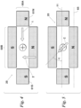
FIG. 4 is a schematic of an embodiment of this disclosure illustrating a combination of multiple magnetic circuits to produce an angled field relative to the target. The magnets of each circuit are aligned in the axial direction of an in-line inspection ("ILI") tool body. -
FIG. 5 is a schematic of the resultant composite field ofFIG. 4 . -
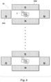
FIG. 6 is a schematic illustrating sensor arrays containing multiple magnetic circuits that each produce an angled field relative to the target. The sensor arrays may be spaced from adjacent sets circumferentially about a single ILI tool body. In some embodiments, two magnetic circuits may be used in each array. -
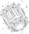
FIG. 7 is an embodiment of this disclosure including an EMAT type technology with a composite field. Multiple instances of the composite field system may be applied to a single ILI tool body. -
FIG. 8 is an embodiment of this disclosure including a MFL type technology with a composite field. The individual arms have sensors to detect the magnetic flux leakage. By way of example, the desired resultant composite field angle is 45°. Compared to designs in which the magnet geometry is spiraled about the ILI tool body (see e.g. FIGS. 3A & 3B), the composite field arrangement enables simpler magnet geometry and a number of other design advantages. -
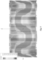
FIG. 9 is an example analysis of magnetic fields on a full tool with a composite field system of this disclosure. - For the purposes of this disclosure, the following definitions apply.
- Angled field - a magnetic field having lines of flux oriented at an angle α relative to the axial direction, 0° < α < 90°.
- Axial direction - the direction at an angle α = 0° relative to a longitudinal axis of a target such as a tubular or pipeline section or an inline inspection tool body.
- Axial field - a magnetic field having lines of flux oriented in axial direction.
- Inline inspection ("ILI") tool body - a generally cylindrical shaped body configured for use in a section of pipeline and extending in the axial direction.
- Magnetic circuit - a pair of opposite polarity magnets, spaced a predetermined distance apart from one another, the magnets being sized and spaced to create a (static) magnetic field oriented in a predetermined direction relative to the ILI tool body. The predetermined directions are the axial and transverse directions of the tool.
- Multiple magnetic circuit -at least two magnetic circuits that each produce their own magnetic field in a first direction and a second different direction, respectively, the first and second fields in combination producing a resultant or composite magnetic field in a third different direction. The magnets of each circuit are not are not angled to reflect the shape of the composite field. The third different direction may be a predetermined selected angle α relative to the axial direction of the ILI tool body. For example, 0° <α < 90° or 40° <α < 50°.
- Sensor array or circuit - One or more sensors located in close proximity to a magnetic circuit and configured for magnetic flux leakage ("MFL") signal detection or electro-magnetic acoustic transducers ("EMAT") signal detection. By way of example, in an EMAT implementation, the sensor array or circuit includes a transmitter and receivers. The sensor array or circuit may have the same orientation as the magnets of the circuit.
- Transverse or circumferential direction - the direction at an angle α = 90° relative to the axial direction.
- Transverse field - a magnetic field having lines of flux oriented in the circumferential direction.
- Referring to
FIGS. 4-9 , embodiments of anILI tool body 10 of this disclosure use multiple magnetic circuits rather than a single magnetic circuit, avoid turning the sensor array or circuit relative to the axial (or transverse) field to create an angled composite field relative to a target, and avoid the complex geometries used in the prior art in which the magnets are arranged to reflect the shape of the desired angled field. In embodiments of this disclosure a plurality of composite magnetic field systems 30 are circumferentially spaced apart from one another about anILI tool body 10, each system 30 including a sensor array orcircuit 40 and at least two magnetic circuits 60. In some embodiments, the composite field system 30 is configured for use in magnetic flux leakage ("MFL") implementations. In other embodiments, the composite field system 30 is configured for use in magnetostrictive-type electro-magnetic acoustic transducers ("EMAT') implementation (as opposed to Lorenz-type EMAT). - The
ILI tool body 10 is typically cylindrical shaped about its centralaxial axis 11. The composite magnetic field system 30 is arranged about the external surface 13 of thetool body 10 between the forward 15 and rearward ends 17 of thetool body 10 For the purposes of this disclosure, the centralaxial axis 11 of thetool body 10 represents the axial direction and the centraltransverse axis 19 of thetool body 10 represents the transverse direction. Thetool body 10 may include a plurality ofwheels 21 mounted onarms 23, and thetool body 10 may be connected to a pigging train or pigging module of kind known in the art for moving inline inspection tools through a pipeline. - In MFL configurations, the
sensor array 40 may include a plurality ofarms 41 includingsensors 43 arranged circumferentially about theILI tool body 10. Theindividual sensors 43 may be of a kind well-known in the art for detecting magnetic flux leakage signals. In EMAT configurations, thesensor array 40 may include at least onetransmitter 45 and a receiver 49 aligned in the axial direction. The central axial axis 47 of thetransmitter 45 is parallel to, or lies in a same plane as, the centralaxial axis 11 of the tool body. Similarly, the centralaxial axis 51 of the receiver 49 is parallel to, and lies in a same plane as the centralaxial axis 11 of thetool body 10. Thetransmitter 45 may be an external piezoelectric transducer or an electro-magnetic acoustic transducer of a kind known in the art. In some embodiments, the receiver 49 may include two receiver coils, one forward and the other rearward (e.g. 49F, 49R) of thetransmitter 45 in the axial direction. In other embodiments, multiple receiver coils are used at eachend tool body 10, the coils being aligned in the axial direction. - According to the invention, the two magnetic circuits 60 may each include
opposite polarity magnets 61N, 61S aligned in the axial direction, the circuits 60 configured relative to one another such that a composite magnetic field C is produced at an angle α relative to the axial direction. One of themagnetic circuits 60A forms a field I in the axial direction and another magnetic circuit 60B forms a field 2 in the transverse direction. According to the invention, eachpole magnet 61N, 61 S of thefirst circuit 60A is spaced apart from one another in the axial direction of theILI tool body 10 and eachpole magnet 61N, 61S of the second circuit 60B is spaced apart from one another in the transverse direction, there being apredetermined size gap 63 between themagnets 61N, 61S. The field 1 or 2 of eachmagnetic circuit 60A, 60B is combined with field 2 or 1 the other 60B, 60A through vector addition to produce a composite angled field C. - By way of a non-limiting example, vector addition of field 1, produced in the axial direction by a first
magnetic circuit 60A, and field 2, produced in the transverse direction by a second magnetic circuit 60B, produce a resultant composite field C lying at an angle α relative to the axial direction. See e.g.FIGS. 4 & 5 . This resultant field C acts as an angled single field through the target even though it is composed of multiple individual fields 1, 2 and even though the magnets 61 of each circuit 60, as well as thetransmitter 45 and receiver 49 of thesensor circuit 40, are aligned in the axial direction. - The resultant magnitude and direction of the composite magnetic field C in targeted regions of a tubular such as a pipe or vessel can be controlled through the arrangement of the individual fields 1 and 2. For example, field 1 and field 2 can be specified to achieve a desired or predetermined, angle α of the resultant composite magnetic field C. In some embodiments, α is in a range of 40° to 50°, with 45° being considered optimal for some 1LI inspection technologies. However, any desired angle α could be achieved in a range of 1° to 89° relative to the axial or transverse direction, there being discrete values and subranges within this broader range.
- The field 1 and 2 magnets 61 may differ from one another in strength to produce the resultant composite angled field. Additionally, the strength of the magnets 61 may vary within each circuit 60. The variations within or between the circuits 60 affect how the fields 1, 2 sum.. The size, shape, or size and shape of the magnets 61 may vary. In some embodiments, the field 1 magnets 61 may be shorter length magnets, with the field 2 magnets 61 being a longer length and located along a respective side of the
transmitter 45. Additionally, the polarity of the magnets 61 may be reversed from those shown in the drawings. Regardless of strength, length, or field direction, each magnet 61 is aligned in the axial direction. In other words, the magnets 61, similar tosensors 41 of thesensor array 40, are oriented so that the central axial axis 65 lies in a same plane as the centralaxial axis 11 of the ILI tool body 10 (and therefore the tubular when in use). - In embodiments, multiple instances of a
composite field system 20 can be applied to asingle ILI body 10. As a result, multiple regions of angled field C can be created with cleaner mechanical layout, there being no need to spiral the magnets 61 about thebody 10 or position the magnets 61 at an angle relative to the target. Instead, the magnets 61 may be arranged in the axial direction. The composite field C provides design options that are not achievable with a single magnetic circuit and can be accomplished in a smaller design envelope. - While embodiments of this disclosure have been described in detail, persons of ordinary skill in the art could make modifications to the embodiments without departing from the scope of the following claims.
Claims (13)
- An inline inspection (ILI) tool body (10) comprising:a plurality of composite magnetic field systems (20), each composite magnetic field system of the plurality containing two magnetic circuits (60A, 60B) arranged relative to one another to provide a resultant magnetic field (C) at an angle α relative to an axial direction of the ILI tool body, where 0° <α < 90°, 0° being the axial direction, 90° being a transverse direction, the resultant magnetic field including a first magnetic field (1) and a second magnetic field (2) and being a vector addition of the first and second magnetic fields (1, 2);each of the two magnetic circuits including a first magnet and a second magnet spaced apart from each other, and arranged such that a pole (61N or 61S) of the first magnet is opposite in polarity to a spaced apart pole (61S or 61N) of the second magnet, each of the first and second magnets oriented at an angle different than the angle α of the resultant magnetic field;a first (60A) of the two magnetic circuits providing the first magnetic field (1) in a first direction, a second (60B) of the two magnetic circuits providing the second magnetic field (2) in a second direction different than that of the first magnetic field;wherein, one of the first and second directions is the axial direction and another one of the first and second directions is the transverse direction.
- The inline inspection (ILI) tool body of claim 1, wherein, the first magnetic field has a first strength and the second magnetic field has a second strength different than that of the first strength.
- The inline inspection (ILI) tool body of any one of the preceding claims, wherein, the angle of orientation of the first and second magnets is the axial direction.
- The inline inspection (ILI) tool body of any one of the preceding claims, further comprising:
each composite magnetic field system including a sensor array (40) configured to detect a corresponding one of the resultant magnetic field. - The inline inspection (ILI) tool body of claim 4, further comprising:
the sensor array including a sensor (43) configured for magnetic flux leakage sensing and/or magnetostrictive electro-magnetic acoustic transducer sensing. - The inline inspection (ILI) tool body of claim 4, further comprising:
the sensor array including sensors (43), each sensor oriented at an angle different than the angle α of a corresponding one of the resultant magnetic field. - The inline inspection (ILI) tool body of any one of the preceding claims, wherein, the angle α is in a range of 40° to 50° or wherein the angle α is 45°.
- A method of inspecting a wall of tubular using an inline inspection (ILI) tool body, the method comprising:collecting data indicative of wall quality using a plurality of composite magnetic field systems (20) arranged about the inline inspection tool body;wherein each composite magnetic field system of the plurality contains two magnetic circuits (60A, 60B) configured to provide a resultant magnetic field (C) at an angle α relative to an axial direction of the ILI tool body, where 0° <α < 90°, 0° being the axial direction, 90° being a transverse direction, the resultant magnetic field including a first magnetic field (1) and a second magnetic field (2) and being a vector addition of the first and second magnetic fields (1, 2); andwherein each of the two magnetic circuits include a first magnet and a second magnet spaced apart from each other, and arranged such that a pole (61N or 61S) of the first magnet is opposite in polarity to a spaced apart pole (61S or 61N) of the second magnet, each of the first and second magnets oriented at an angle different than the angle α of the resultant magnetic field; andwherein a first (60A) of the two magnetic circuits provides the first magnetic field (1) in a first direction, a second (60B) of the two magnetic circuits provides the second magnetic field (2) in a second direction different than that of the first magnetic field;wherein, one of the first and second directions is the axial direction and another one of the first and second directions is the transverse direction.
- The method of claim 8, wherein, the first magnetic field has a first strength and the second magnetic field has a second strength different than that of the first strength.
- The method of any one of claims 8 to 9, wherein, the angle of orientation of the first and second magnets is the axial direction.
- The method of any one of claims 8 to 10, wherein, each composite magnetic field system includes a sensor array (40) configured to detect a corresponding one of the resultant magnetic field.
- The method of claim 11, wherein, the sensor array includes a sensor (43) configured for magnetic flux leakage sensing and/or for magnetostrictive electro-magnetic acoustic transducer sensing and/or the sensor array includes sensors (43), each sensor oriented at an angle different than the angle α of a corresponding one of the resultant magnetic field.
- The method of any one of claims 8 to 12, wherein, the angle α is in a range of 40° to 50° or wherein the angle α is 45°.
Applications Claiming Priority (2)
| Application Number | Priority Date | Filing Date | Title |
|---|---|---|---|
| US201962832663P | 2019-04-11 | 2019-04-11 | |
| PCT/IB2020/000306 WO2020208422A2 (en) | 2019-04-11 | 2020-04-10 | Pipeline tool with composite magnetic field for inline inspection |
Publications (2)
| Publication Number | Publication Date |
|---|---|
| EP3953700A2 EP3953700A2 (en) | 2022-02-16 |
| EP3953700B1 true EP3953700B1 (en) | 2024-04-24 |
Family
ID=71728759
Family Applications (1)
| Application Number | Title | Priority Date | Filing Date |
|---|---|---|---|
| EP20743218.8A Active EP3953700B1 (en) | 2019-04-11 | 2020-04-10 | Pipeline tool with composite magnetic field for inline inspection |
Country Status (7)
| Country | Link |
|---|---|
| US (2) | US11460442B2 (en) |
| EP (1) | EP3953700B1 (en) |
| AU (1) | AU2020272196A1 (en) |
| BR (1) | BR112021015259A2 (en) |
| CA (1) | CA3127467C (en) |
| MX (1) | MX2021010623A (en) |
| WO (1) | WO2020208422A2 (en) |
Families Citing this family (1)
| Publication number | Priority date | Publication date | Assignee | Title |
|---|---|---|---|---|
| CN118795018B (en) * | 2024-09-11 | 2024-11-26 | 四川大学 | Electromagnetic and ultrasonic fusion detection device and method for wellhead drill pipe |
Citations (3)
| Publication number | Priority date | Publication date | Assignee | Title |
|---|---|---|---|---|
| EP0152687A1 (en) * | 1983-12-27 | 1985-08-28 | The Babcock & Wilcox Company | Tube inspection apparatus |
| EP1063521B1 (en) * | 1999-06-25 | 2007-04-18 | PII Pipetronix GmbH | Device for testing ferromagnetic tubes |
| US20110163741A1 (en) * | 2008-05-15 | 2011-07-07 | Sumitomo Metal Industries, Ltd. | Magnetic testing method and magnetic testing apparatus |
Family Cites Families (16)
| Publication number | Priority date | Publication date | Assignee | Title |
|---|---|---|---|---|
| GB2044459B (en) * | 1979-03-16 | 1983-10-26 | British Gas Corp | Velocity correction arrangement for non-destructive testing apparatus |
| US4439733A (en) * | 1980-08-29 | 1984-03-27 | Technicare Corporation | Distributed phase RF coil |
| US4456881A (en) * | 1982-01-18 | 1984-06-26 | Technicare Corporation | Gradient-coil apparatus for a magnetic resonance system |
| DE3837487A1 (en) * | 1988-11-04 | 1990-05-10 | Leybold Ag | METHOD AND DEVICE FOR ETCHING SUBSTRATES WITH A MAGNETIC FIELD SUPPORTED LOW PRESSURE DISCHARGE |
| SE462820B (en) * | 1989-01-16 | 1990-09-03 | Asea Brown Boveri | MAGNETIC CIRCUIT |
| EP0501169B1 (en) * | 1991-02-25 | 1995-08-23 | Asea Brown Boveri Ag | Device for measuring field-strength |
| DE4319146C2 (en) * | 1993-06-09 | 1999-02-04 | Inst Mikrostrukturtechnologie | Magnetic field sensor, made up of a magnetic reversal line and one or more magnetoresistive resistors |
| DE19543481C2 (en) * | 1995-11-22 | 1997-10-23 | Pipetronix Gmbh | Device for testing ferromagnetic materials |
| US7923994B2 (en) * | 2008-11-12 | 2011-04-12 | Hoyt Philip M | Spiral magnetic field apparatus and method for pipeline inspection |
| US8479577B2 (en) | 2009-02-09 | 2013-07-09 | Weatherford/Lab, Inc. | In-line inspection tool for pipeline integrity testing |
| US8653811B2 (en) * | 2009-06-26 | 2014-02-18 | Tdw Delaware Inc. | Pipeline inspection tool with oblique magnetizer |
| US8319494B2 (en) | 2009-06-26 | 2012-11-27 | Tdw Delaware Inc. | Pipeline inspection tool with double spiral EMAT sensor array |
| CA2976796A1 (en) * | 2015-02-23 | 2016-09-01 | Source 1 Environmental, Llc | Pipe repair apparatus and method |
| EP3389881B1 (en) * | 2016-02-01 | 2022-05-11 | PTT Exploration And Production Public Company Limited | System and method for use in the treatment of a pipeline |
| DE102017124542B4 (en) * | 2017-10-20 | 2023-12-21 | Infineon Technologies Ag | MAGNETIC FIELD SENSOR ARRANGEMENT AND METHOD FOR MEASURING AN EXTERNAL MAGNETIC FIELD |
| CA3108804A1 (en) * | 2018-08-08 | 2020-02-13 | Pure Technologies Ltd. | Method and apparatus to detect flaws in metallic pipe |
-
2020
- 2020-04-10 AU AU2020272196A patent/AU2020272196A1/en not_active Abandoned
- 2020-04-10 EP EP20743218.8A patent/EP3953700B1/en active Active
- 2020-04-10 BR BR112021015259-8A patent/BR112021015259A2/en not_active Application Discontinuation
- 2020-04-10 WO PCT/IB2020/000306 patent/WO2020208422A2/en not_active Ceased
- 2020-04-10 CA CA3127467A patent/CA3127467C/en active Active
- 2020-04-10 MX MX2021010623A patent/MX2021010623A/en unknown
- 2020-04-10 US US16/845,658 patent/US11460442B2/en active Active
-
2022
- 2022-10-03 US US17/937,698 patent/US20230096829A1/en not_active Abandoned
Patent Citations (3)
| Publication number | Priority date | Publication date | Assignee | Title |
|---|---|---|---|---|
| EP0152687A1 (en) * | 1983-12-27 | 1985-08-28 | The Babcock & Wilcox Company | Tube inspection apparatus |
| EP1063521B1 (en) * | 1999-06-25 | 2007-04-18 | PII Pipetronix GmbH | Device for testing ferromagnetic tubes |
| US20110163741A1 (en) * | 2008-05-15 | 2011-07-07 | Sumitomo Metal Industries, Ltd. | Magnetic testing method and magnetic testing apparatus |
Also Published As
| Publication number | Publication date |
|---|---|
| BR112021015259A2 (en) | 2021-10-26 |
| WO2020208422A2 (en) | 2020-10-15 |
| WO2020208422A3 (en) | 2020-11-26 |
| US20230096829A1 (en) | 2023-03-30 |
| US11460442B2 (en) | 2022-10-04 |
| CA3127467A1 (en) | 2020-10-15 |
| CA3127467C (en) | 2024-01-02 |
| EP3953700A2 (en) | 2022-02-16 |
| AU2020272196A1 (en) | 2021-08-05 |
| MX2021010623A (en) | 2021-11-04 |
| US20200326310A1 (en) | 2020-10-15 |
Similar Documents
| Publication | Publication Date | Title |
|---|---|---|
| CA2791440C (en) | Spiral magnetic field apparatus and method for pipeline inspection | |
| KR101729039B1 (en) | Pipeline Inspection Tool with Double Spiral EMAT Sensor Array | |
| US8319494B2 (en) | Pipeline inspection tool with double spiral EMAT sensor array | |
| AU2010201831B2 (en) | Magnetising assembly | |
| US9201045B2 (en) | Internal and external universal EMAT inspection devices and related methods | |
| CN101936950B (en) | Pipeline inspection tool with oblique magnetizer | |
| US20230096829A1 (en) | Pipeline Tool with Composite Magnetic Field for Inline Inspection | |
| CN116930325B (en) | Electromagnetic and ultrasonic hybrid transducer for metal pipeline defect imaging | |
| US20250052718A1 (en) | Circumferential magnetizer for a pipeline inspection gauge | |
| US20190128854A1 (en) | Scanner magnetic wheel system for close traction on pipes and pipe elbows | |
| GB2471386A (en) | Pipeline inspection tool with double spiral EMAT sensor array | |
| CA3017281C (en) | Guided wave testing | |
| US10352909B2 (en) | Paired magnetostrictive transducers for non destructive testing of tubular structures with selective torsional or flexural wave modes | |
| CA3017281A1 (en) | Guided wave testing |
Legal Events
| Date | Code | Title | Description |
|---|---|---|---|
| STAA | Information on the status of an ep patent application or granted ep patent |
Free format text: STATUS: UNKNOWN |
|
| STAA | Information on the status of an ep patent application or granted ep patent |
Free format text: STATUS: THE INTERNATIONAL PUBLICATION HAS BEEN MADE |
|
| PUAI | Public reference made under article 153(3) epc to a published international application that has entered the european phase |
Free format text: ORIGINAL CODE: 0009012 |
|
| STAA | Information on the status of an ep patent application or granted ep patent |
Free format text: STATUS: REQUEST FOR EXAMINATION WAS MADE |
|
| 17P | Request for examination filed |
Effective date: 20210707 |
|
| AK | Designated contracting states |
Kind code of ref document: A2 Designated state(s): AL AT BE BG CH CY CZ DE DK EE ES FI FR GB GR HR HU IE IS IT LI LT LU LV MC MK MT NL NO PL PT RO RS SE SI SK SM TR |
|
| DAV | Request for validation of the european patent (deleted) | ||
| DAX | Request for extension of the european patent (deleted) | ||
| P01 | Opt-out of the competence of the unified patent court (upc) registered |
Effective date: 20230530 |
|
| GRAP | Despatch of communication of intention to grant a patent |
Free format text: ORIGINAL CODE: EPIDOSNIGR1 |
|
| STAA | Information on the status of an ep patent application or granted ep patent |
Free format text: STATUS: GRANT OF PATENT IS INTENDED |
|
| INTG | Intention to grant announced |
Effective date: 20231117 |
|
| GRAS | Grant fee paid |
Free format text: ORIGINAL CODE: EPIDOSNIGR3 |
|
| GRAA | (expected) grant |
Free format text: ORIGINAL CODE: 0009210 |
|
| STAA | Information on the status of an ep patent application or granted ep patent |
Free format text: STATUS: THE PATENT HAS BEEN GRANTED |
|
| AK | Designated contracting states |
Kind code of ref document: B1 Designated state(s): AL AT BE BG CH CY CZ DE DK EE ES FI FR GB GR HR HU IE IS IT LI LT LU LV MC MK MT NL NO PL PT RO RS SE SI SK SM TR |
|
| REG | Reference to a national code |
Ref country code: GB Ref legal event code: FG4D |
|
| REG | Reference to a national code |
Ref country code: CH Ref legal event code: EP |
|
| REG | Reference to a national code |
Ref country code: DE Ref legal event code: R096 Ref document number: 602020029623 Country of ref document: DE |
|
| REG | Reference to a national code |
Ref country code: IE Ref legal event code: FG4D |
|
| REG | Reference to a national code |
Ref country code: LT Ref legal event code: MG9D |
|
| REG | Reference to a national code |
Ref country code: NL Ref legal event code: MP Effective date: 20240424 |
|
| REG | Reference to a national code |
Ref country code: AT Ref legal event code: MK05 Ref document number: 1680098 Country of ref document: AT Kind code of ref document: T Effective date: 20240424 |
|
| PG25 | Lapsed in a contracting state [announced via postgrant information from national office to epo] |
Ref country code: NL Free format text: LAPSE BECAUSE OF FAILURE TO SUBMIT A TRANSLATION OF THE DESCRIPTION OR TO PAY THE FEE WITHIN THE PRESCRIBED TIME-LIMIT Effective date: 20240424 |
|
| PG25 | Lapsed in a contracting state [announced via postgrant information from national office to epo] |
Ref country code: NL Free format text: LAPSE BECAUSE OF FAILURE TO SUBMIT A TRANSLATION OF THE DESCRIPTION OR TO PAY THE FEE WITHIN THE PRESCRIBED TIME-LIMIT Effective date: 20240424 |
|
| PG25 | Lapsed in a contracting state [announced via postgrant information from national office to epo] |
Ref country code: IS Free format text: LAPSE BECAUSE OF FAILURE TO SUBMIT A TRANSLATION OF THE DESCRIPTION OR TO PAY THE FEE WITHIN THE PRESCRIBED TIME-LIMIT Effective date: 20240824 |
|
| PG25 | Lapsed in a contracting state [announced via postgrant information from national office to epo] |
Ref country code: BG Free format text: LAPSE BECAUSE OF FAILURE TO SUBMIT A TRANSLATION OF THE DESCRIPTION OR TO PAY THE FEE WITHIN THE PRESCRIBED TIME-LIMIT Effective date: 20240424 |
|
| PG25 | Lapsed in a contracting state [announced via postgrant information from national office to epo] |
Ref country code: FI Free format text: LAPSE BECAUSE OF FAILURE TO SUBMIT A TRANSLATION OF THE DESCRIPTION OR TO PAY THE FEE WITHIN THE PRESCRIBED TIME-LIMIT Effective date: 20240424 Ref country code: HR Free format text: LAPSE BECAUSE OF FAILURE TO SUBMIT A TRANSLATION OF THE DESCRIPTION OR TO PAY THE FEE WITHIN THE PRESCRIBED TIME-LIMIT Effective date: 20240424 |
|
| PG25 | Lapsed in a contracting state [announced via postgrant information from national office to epo] |
Ref country code: GR Free format text: LAPSE BECAUSE OF FAILURE TO SUBMIT A TRANSLATION OF THE DESCRIPTION OR TO PAY THE FEE WITHIN THE PRESCRIBED TIME-LIMIT Effective date: 20240725 |
|
| PG25 | Lapsed in a contracting state [announced via postgrant information from national office to epo] |
Ref country code: PT Free format text: LAPSE BECAUSE OF FAILURE TO SUBMIT A TRANSLATION OF THE DESCRIPTION OR TO PAY THE FEE WITHIN THE PRESCRIBED TIME-LIMIT Effective date: 20240826 |
|
| PG25 | Lapsed in a contracting state [announced via postgrant information from national office to epo] |
Ref country code: ES Free format text: LAPSE BECAUSE OF FAILURE TO SUBMIT A TRANSLATION OF THE DESCRIPTION OR TO PAY THE FEE WITHIN THE PRESCRIBED TIME-LIMIT Effective date: 20240424 |
|
| PG25 | Lapsed in a contracting state [announced via postgrant information from national office to epo] |
Ref country code: AT Free format text: LAPSE BECAUSE OF FAILURE TO SUBMIT A TRANSLATION OF THE DESCRIPTION OR TO PAY THE FEE WITHIN THE PRESCRIBED TIME-LIMIT Effective date: 20240424 |
|
| PG25 | Lapsed in a contracting state [announced via postgrant information from national office to epo] |
Ref country code: PL Free format text: LAPSE BECAUSE OF FAILURE TO SUBMIT A TRANSLATION OF THE DESCRIPTION OR TO PAY THE FEE WITHIN THE PRESCRIBED TIME-LIMIT Effective date: 20240424 |
|
| PG25 | Lapsed in a contracting state [announced via postgrant information from national office to epo] |
Ref country code: LV Free format text: LAPSE BECAUSE OF FAILURE TO SUBMIT A TRANSLATION OF THE DESCRIPTION OR TO PAY THE FEE WITHIN THE PRESCRIBED TIME-LIMIT Effective date: 20240424 |
|
| PG25 | Lapsed in a contracting state [announced via postgrant information from national office to epo] |
Ref country code: PT Free format text: LAPSE BECAUSE OF FAILURE TO SUBMIT A TRANSLATION OF THE DESCRIPTION OR TO PAY THE FEE WITHIN THE PRESCRIBED TIME-LIMIT Effective date: 20240826 Ref country code: PL Free format text: LAPSE BECAUSE OF FAILURE TO SUBMIT A TRANSLATION OF THE DESCRIPTION OR TO PAY THE FEE WITHIN THE PRESCRIBED TIME-LIMIT Effective date: 20240424 Ref country code: LV Free format text: LAPSE BECAUSE OF FAILURE TO SUBMIT A TRANSLATION OF THE DESCRIPTION OR TO PAY THE FEE WITHIN THE PRESCRIBED TIME-LIMIT Effective date: 20240424 Ref country code: IS Free format text: LAPSE BECAUSE OF FAILURE TO SUBMIT A TRANSLATION OF THE DESCRIPTION OR TO PAY THE FEE WITHIN THE PRESCRIBED TIME-LIMIT Effective date: 20240824 Ref country code: HR Free format text: LAPSE BECAUSE OF FAILURE TO SUBMIT A TRANSLATION OF THE DESCRIPTION OR TO PAY THE FEE WITHIN THE PRESCRIBED TIME-LIMIT Effective date: 20240424 Ref country code: GR Free format text: LAPSE BECAUSE OF FAILURE TO SUBMIT A TRANSLATION OF THE DESCRIPTION OR TO PAY THE FEE WITHIN THE PRESCRIBED TIME-LIMIT Effective date: 20240725 Ref country code: FI Free format text: LAPSE BECAUSE OF FAILURE TO SUBMIT A TRANSLATION OF THE DESCRIPTION OR TO PAY THE FEE WITHIN THE PRESCRIBED TIME-LIMIT Effective date: 20240424 Ref country code: ES Free format text: LAPSE BECAUSE OF FAILURE TO SUBMIT A TRANSLATION OF THE DESCRIPTION OR TO PAY THE FEE WITHIN THE PRESCRIBED TIME-LIMIT Effective date: 20240424 Ref country code: BG Free format text: LAPSE BECAUSE OF FAILURE TO SUBMIT A TRANSLATION OF THE DESCRIPTION OR TO PAY THE FEE WITHIN THE PRESCRIBED TIME-LIMIT Effective date: 20240424 Ref country code: AT Free format text: LAPSE BECAUSE OF FAILURE TO SUBMIT A TRANSLATION OF THE DESCRIPTION OR TO PAY THE FEE WITHIN THE PRESCRIBED TIME-LIMIT Effective date: 20240424 Ref country code: RS Free format text: LAPSE BECAUSE OF FAILURE TO SUBMIT A TRANSLATION OF THE DESCRIPTION OR TO PAY THE FEE WITHIN THE PRESCRIBED TIME-LIMIT Effective date: 20240724 |
|
| PG25 | Lapsed in a contracting state [announced via postgrant information from national office to epo] |
Ref country code: DK Free format text: LAPSE BECAUSE OF FAILURE TO SUBMIT A TRANSLATION OF THE DESCRIPTION OR TO PAY THE FEE WITHIN THE PRESCRIBED TIME-LIMIT Effective date: 20240424 |
|
| PG25 | Lapsed in a contracting state [announced via postgrant information from national office to epo] |
Ref country code: EE Free format text: LAPSE BECAUSE OF FAILURE TO SUBMIT A TRANSLATION OF THE DESCRIPTION OR TO PAY THE FEE WITHIN THE PRESCRIBED TIME-LIMIT Effective date: 20240424 |
|
| PG25 | Lapsed in a contracting state [announced via postgrant information from national office to epo] |
Ref country code: CZ Free format text: LAPSE BECAUSE OF FAILURE TO SUBMIT A TRANSLATION OF THE DESCRIPTION OR TO PAY THE FEE WITHIN THE PRESCRIBED TIME-LIMIT Effective date: 20240424 |
|
| PG25 | Lapsed in a contracting state [announced via postgrant information from national office to epo] |
Ref country code: RO Free format text: LAPSE BECAUSE OF FAILURE TO SUBMIT A TRANSLATION OF THE DESCRIPTION OR TO PAY THE FEE WITHIN THE PRESCRIBED TIME-LIMIT Effective date: 20240424 Ref country code: SK Free format text: LAPSE BECAUSE OF FAILURE TO SUBMIT A TRANSLATION OF THE DESCRIPTION OR TO PAY THE FEE WITHIN THE PRESCRIBED TIME-LIMIT Effective date: 20240424 |
|
| REG | Reference to a national code |
Ref country code: DE Ref legal event code: R097 Ref document number: 602020029623 Country of ref document: DE |
|
| PG25 | Lapsed in a contracting state [announced via postgrant information from national office to epo] |
Ref country code: SM Free format text: LAPSE BECAUSE OF FAILURE TO SUBMIT A TRANSLATION OF THE DESCRIPTION OR TO PAY THE FEE WITHIN THE PRESCRIBED TIME-LIMIT Effective date: 20240424 |
|
| PG25 | Lapsed in a contracting state [announced via postgrant information from national office to epo] |
Ref country code: SM Free format text: LAPSE BECAUSE OF FAILURE TO SUBMIT A TRANSLATION OF THE DESCRIPTION OR TO PAY THE FEE WITHIN THE PRESCRIBED TIME-LIMIT Effective date: 20240424 Ref country code: SK Free format text: LAPSE BECAUSE OF FAILURE TO SUBMIT A TRANSLATION OF THE DESCRIPTION OR TO PAY THE FEE WITHIN THE PRESCRIBED TIME-LIMIT Effective date: 20240424 Ref country code: RO Free format text: LAPSE BECAUSE OF FAILURE TO SUBMIT A TRANSLATION OF THE DESCRIPTION OR TO PAY THE FEE WITHIN THE PRESCRIBED TIME-LIMIT Effective date: 20240424 Ref country code: EE Free format text: LAPSE BECAUSE OF FAILURE TO SUBMIT A TRANSLATION OF THE DESCRIPTION OR TO PAY THE FEE WITHIN THE PRESCRIBED TIME-LIMIT Effective date: 20240424 Ref country code: DK Free format text: LAPSE BECAUSE OF FAILURE TO SUBMIT A TRANSLATION OF THE DESCRIPTION OR TO PAY THE FEE WITHIN THE PRESCRIBED TIME-LIMIT Effective date: 20240424 Ref country code: CZ Free format text: LAPSE BECAUSE OF FAILURE TO SUBMIT A TRANSLATION OF THE DESCRIPTION OR TO PAY THE FEE WITHIN THE PRESCRIBED TIME-LIMIT Effective date: 20240424 |
|
| PLBE | No opposition filed within time limit |
Free format text: ORIGINAL CODE: 0009261 |
|
| STAA | Information on the status of an ep patent application or granted ep patent |
Free format text: STATUS: NO OPPOSITION FILED WITHIN TIME LIMIT |
|
| 26N | No opposition filed |
Effective date: 20250127 |
|
| PG25 | Lapsed in a contracting state [announced via postgrant information from national office to epo] |
Ref country code: SI Free format text: LAPSE BECAUSE OF FAILURE TO SUBMIT A TRANSLATION OF THE DESCRIPTION OR TO PAY THE FEE WITHIN THE PRESCRIBED TIME-LIMIT Effective date: 20240424 |
|
| PG25 | Lapsed in a contracting state [announced via postgrant information from national office to epo] |
Ref country code: SE Free format text: LAPSE BECAUSE OF FAILURE TO SUBMIT A TRANSLATION OF THE DESCRIPTION OR TO PAY THE FEE WITHIN THE PRESCRIBED TIME-LIMIT Effective date: 20240424 |
|
| REG | Reference to a national code |
Ref country code: DE Ref legal event code: R119 Ref document number: 602020029623 Country of ref document: DE |
|
| REG | Reference to a national code |
Ref country code: CH Ref legal event code: H13 Free format text: ST27 STATUS EVENT CODE: U-0-0-H10-H13 (AS PROVIDED BY THE NATIONAL OFFICE) Effective date: 20251125 |
|
| PG25 | Lapsed in a contracting state [announced via postgrant information from national office to epo] |
Ref country code: LU Free format text: LAPSE BECAUSE OF NON-PAYMENT OF DUE FEES Effective date: 20250410 |
|
| PG25 | Lapsed in a contracting state [announced via postgrant information from national office to epo] |
Ref country code: MC Free format text: LAPSE BECAUSE OF FAILURE TO SUBMIT A TRANSLATION OF THE DESCRIPTION OR TO PAY THE FEE WITHIN THE PRESCRIBED TIME-LIMIT Effective date: 20240424 |
|
| GBPC | Gb: european patent ceased through non-payment of renewal fee |
Effective date: 20250410 |
|
| REG | Reference to a national code |
Ref country code: BE Ref legal event code: MM Effective date: 20250430 |
|
| PG25 | Lapsed in a contracting state [announced via postgrant information from national office to epo] |
Ref country code: DE Free format text: LAPSE BECAUSE OF NON-PAYMENT OF DUE FEES Effective date: 20251104 |
|
| PG25 | Lapsed in a contracting state [announced via postgrant information from national office to epo] |
Ref country code: GB Free format text: LAPSE BECAUSE OF NON-PAYMENT OF DUE FEES Effective date: 20250410 |
|
| PG25 | Lapsed in a contracting state [announced via postgrant information from national office to epo] |
Ref country code: NO Free format text: LAPSE BECAUSE OF NON-PAYMENT OF DUE FEES Effective date: 20250430 |
|
| PG25 | Lapsed in a contracting state [announced via postgrant information from national office to epo] |
Ref country code: FR Free format text: LAPSE BECAUSE OF NON-PAYMENT OF DUE FEES Effective date: 20250430 |
|
| PG25 | Lapsed in a contracting state [announced via postgrant information from national office to epo] |
Ref country code: BE Free format text: LAPSE BECAUSE OF NON-PAYMENT OF DUE FEES Effective date: 20250430 |
|
| PG25 | Lapsed in a contracting state [announced via postgrant information from national office to epo] |
Ref country code: CH Free format text: LAPSE BECAUSE OF NON-PAYMENT OF DUE FEES Effective date: 20250430 |
|
| PG25 | Lapsed in a contracting state [announced via postgrant information from national office to epo] |
Ref country code: IT Free format text: LAPSE BECAUSE OF FAILURE TO SUBMIT A TRANSLATION OF THE DESCRIPTION OR TO PAY THE FEE WITHIN THE PRESCRIBED TIME-LIMIT Effective date: 20240424 |
|
| PG25 | Lapsed in a contracting state [announced via postgrant information from national office to epo] |
Ref country code: IE Free format text: LAPSE BECAUSE OF NON-PAYMENT OF DUE FEES Effective date: 20250410 |