EP3953228B1 - Vehicle localisation - Google Patents
Vehicle localisation Download PDFInfo
- Publication number
- EP3953228B1 EP3953228B1 EP20717186.9A EP20717186A EP3953228B1 EP 3953228 B1 EP3953228 B1 EP 3953228B1 EP 20717186 A EP20717186 A EP 20717186A EP 3953228 B1 EP3953228 B1 EP 3953228B1
- Authority
- EP
- European Patent Office
- Prior art keywords
- vehicle
- sensor
- sensor arrangement
- control system
- orientation
- Prior art date
- Legal status (The legal status is an assumption and is not a legal conclusion. Google has not performed a legal analysis and makes no representation as to the accuracy of the status listed.)
- Active
Links
Images




Classifications
-
- B—PERFORMING OPERATIONS; TRANSPORTING
- B60—VEHICLES IN GENERAL
- B60W—CONJOINT CONTROL OF VEHICLE SUB-UNITS OF DIFFERENT TYPE OR DIFFERENT FUNCTION; CONTROL SYSTEMS SPECIALLY ADAPTED FOR HYBRID VEHICLES; ROAD VEHICLE DRIVE CONTROL SYSTEMS FOR PURPOSES NOT RELATED TO THE CONTROL OF A PARTICULAR SUB-UNIT
- B60W50/00—Details of control systems for road vehicle drive control not related to the control of a particular sub-unit, e.g. process diagnostic or vehicle driver interfaces
- B60W50/02—Ensuring safety in case of control system failures, e.g. by diagnosing, circumventing or fixing failures
- B60W50/029—Adapting to failures or work around with other constraints, e.g. circumvention by avoiding use of failed parts
-
- B—PERFORMING OPERATIONS; TRANSPORTING
- B60—VEHICLES IN GENERAL
- B60R—VEHICLES, VEHICLE FITTINGS, OR VEHICLE PARTS, NOT OTHERWISE PROVIDED FOR
- B60R16/00—Electric or fluid circuits specially adapted for vehicles and not otherwise provided for; Arrangement of elements of electric or fluid circuits specially adapted for vehicles and not otherwise provided for
- B60R16/02—Electric or fluid circuits specially adapted for vehicles and not otherwise provided for; Arrangement of elements of electric or fluid circuits specially adapted for vehicles and not otherwise provided for electric constitutive elements
- B60R16/03—Electric or fluid circuits specially adapted for vehicles and not otherwise provided for; Arrangement of elements of electric or fluid circuits specially adapted for vehicles and not otherwise provided for electric constitutive elements for supply of electrical power to vehicle subsystems or for
- B60R16/033—Electric or fluid circuits specially adapted for vehicles and not otherwise provided for; Arrangement of elements of electric or fluid circuits specially adapted for vehicles and not otherwise provided for electric constitutive elements for supply of electrical power to vehicle subsystems or for characterised by the use of electrical cells or batteries
-
- B—PERFORMING OPERATIONS; TRANSPORTING
- B60—VEHICLES IN GENERAL
- B60W—CONJOINT CONTROL OF VEHICLE SUB-UNITS OF DIFFERENT TYPE OR DIFFERENT FUNCTION; CONTROL SYSTEMS SPECIALLY ADAPTED FOR HYBRID VEHICLES; ROAD VEHICLE DRIVE CONTROL SYSTEMS FOR PURPOSES NOT RELATED TO THE CONTROL OF A PARTICULAR SUB-UNIT
- B60W30/00—Purposes of road vehicle drive control systems not related to the control of a particular sub-unit, e.g. of systems using conjoint control of vehicle sub-units
- B60W30/10—Path keeping
- B60W30/12—Lane keeping
-
- B—PERFORMING OPERATIONS; TRANSPORTING
- B60—VEHICLES IN GENERAL
- B60W—CONJOINT CONTROL OF VEHICLE SUB-UNITS OF DIFFERENT TYPE OR DIFFERENT FUNCTION; CONTROL SYSTEMS SPECIALLY ADAPTED FOR HYBRID VEHICLES; ROAD VEHICLE DRIVE CONTROL SYSTEMS FOR PURPOSES NOT RELATED TO THE CONTROL OF A PARTICULAR SUB-UNIT
- B60W40/00—Estimation or calculation of non-directly measurable driving parameters for road vehicle drive control systems not related to the control of a particular sub unit, e.g. by using mathematical models
- B60W40/02—Estimation or calculation of non-directly measurable driving parameters for road vehicle drive control systems not related to the control of a particular sub unit, e.g. by using mathematical models related to ambient conditions
- B60W40/06—Road conditions
- B60W40/072—Curvature of the road
-
- B—PERFORMING OPERATIONS; TRANSPORTING
- B60—VEHICLES IN GENERAL
- B60W—CONJOINT CONTROL OF VEHICLE SUB-UNITS OF DIFFERENT TYPE OR DIFFERENT FUNCTION; CONTROL SYSTEMS SPECIALLY ADAPTED FOR HYBRID VEHICLES; ROAD VEHICLE DRIVE CONTROL SYSTEMS FOR PURPOSES NOT RELATED TO THE CONTROL OF A PARTICULAR SUB-UNIT
- B60W50/00—Details of control systems for road vehicle drive control not related to the control of a particular sub-unit, e.g. process diagnostic or vehicle driver interfaces
- B60W50/08—Interaction between the driver and the control system
- B60W50/14—Means for informing the driver, warning the driver or prompting a driver intervention
-
- G—PHYSICS
- G01—MEASURING; TESTING
- G01S—RADIO DIRECTION-FINDING; RADIO NAVIGATION; DETERMINING DISTANCE OR VELOCITY BY USE OF RADIO WAVES; LOCATING OR PRESENCE-DETECTING BY USE OF THE REFLECTION OR RERADIATION OF RADIO WAVES; ANALOGOUS ARRANGEMENTS USING OTHER WAVES
- G01S17/00—Systems using the reflection or reradiation of electromagnetic waves other than radio waves, e.g. lidar systems
- G01S17/88—Lidar systems specially adapted for specific applications
- G01S17/93—Lidar systems specially adapted for specific applications for anti-collision purposes
- G01S17/931—Lidar systems specially adapted for specific applications for anti-collision purposes of land vehicles
-
- G—PHYSICS
- G06—COMPUTING OR CALCULATING; COUNTING
- G06V—IMAGE OR VIDEO RECOGNITION OR UNDERSTANDING
- G06V20/00—Scenes; Scene-specific elements
- G06V20/50—Context or environment of the image
- G06V20/56—Context or environment of the image exterior to a vehicle by using sensors mounted on the vehicle
- G06V20/588—Recognition of the road, e.g. of lane markings; Recognition of the vehicle driving pattern in relation to the road
-
- B—PERFORMING OPERATIONS; TRANSPORTING
- B60—VEHICLES IN GENERAL
- B60W—CONJOINT CONTROL OF VEHICLE SUB-UNITS OF DIFFERENT TYPE OR DIFFERENT FUNCTION; CONTROL SYSTEMS SPECIALLY ADAPTED FOR HYBRID VEHICLES; ROAD VEHICLE DRIVE CONTROL SYSTEMS FOR PURPOSES NOT RELATED TO THE CONTROL OF A PARTICULAR SUB-UNIT
- B60W2420/00—Indexing codes relating to the type of sensors based on the principle of their operation
- B60W2420/40—Photo, light or radio wave sensitive means, e.g. infrared sensors
- B60W2420/403—Image sensing, e.g. optical camera
-
- B—PERFORMING OPERATIONS; TRANSPORTING
- B60—VEHICLES IN GENERAL
- B60W—CONJOINT CONTROL OF VEHICLE SUB-UNITS OF DIFFERENT TYPE OR DIFFERENT FUNCTION; CONTROL SYSTEMS SPECIALLY ADAPTED FOR HYBRID VEHICLES; ROAD VEHICLE DRIVE CONTROL SYSTEMS FOR PURPOSES NOT RELATED TO THE CONTROL OF A PARTICULAR SUB-UNIT
- B60W2420/00—Indexing codes relating to the type of sensors based on the principle of their operation
- B60W2420/40—Photo, light or radio wave sensitive means, e.g. infrared sensors
- B60W2420/408—Radar; Laser, e.g. lidar
-
- B—PERFORMING OPERATIONS; TRANSPORTING
- B60—VEHICLES IN GENERAL
- B60W—CONJOINT CONTROL OF VEHICLE SUB-UNITS OF DIFFERENT TYPE OR DIFFERENT FUNCTION; CONTROL SYSTEMS SPECIALLY ADAPTED FOR HYBRID VEHICLES; ROAD VEHICLE DRIVE CONTROL SYSTEMS FOR PURPOSES NOT RELATED TO THE CONTROL OF A PARTICULAR SUB-UNIT
- B60W2422/00—Indexing codes relating to the special location or mounting of sensors
- B60W2422/90—Indexing codes relating to the special location or mounting of sensors on bumper, e.g. collision sensor
-
- B—PERFORMING OPERATIONS; TRANSPORTING
- B60—VEHICLES IN GENERAL
- B60W—CONJOINT CONTROL OF VEHICLE SUB-UNITS OF DIFFERENT TYPE OR DIFFERENT FUNCTION; CONTROL SYSTEMS SPECIALLY ADAPTED FOR HYBRID VEHICLES; ROAD VEHICLE DRIVE CONTROL SYSTEMS FOR PURPOSES NOT RELATED TO THE CONTROL OF A PARTICULAR SUB-UNIT
- B60W2422/00—Indexing codes relating to the special location or mounting of sensors
- B60W2422/95—Measuring the same parameter at multiple locations of the vehicle
-
- B—PERFORMING OPERATIONS; TRANSPORTING
- B60—VEHICLES IN GENERAL
- B60W—CONJOINT CONTROL OF VEHICLE SUB-UNITS OF DIFFERENT TYPE OR DIFFERENT FUNCTION; CONTROL SYSTEMS SPECIALLY ADAPTED FOR HYBRID VEHICLES; ROAD VEHICLE DRIVE CONTROL SYSTEMS FOR PURPOSES NOT RELATED TO THE CONTROL OF A PARTICULAR SUB-UNIT
- B60W2552/00—Input parameters relating to infrastructure
- B60W2552/30—Road curve radius
-
- B—PERFORMING OPERATIONS; TRANSPORTING
- B60—VEHICLES IN GENERAL
- B60W—CONJOINT CONTROL OF VEHICLE SUB-UNITS OF DIFFERENT TYPE OR DIFFERENT FUNCTION; CONTROL SYSTEMS SPECIALLY ADAPTED FOR HYBRID VEHICLES; ROAD VEHICLE DRIVE CONTROL SYSTEMS FOR PURPOSES NOT RELATED TO THE CONTROL OF A PARTICULAR SUB-UNIT
- B60W2552/00—Input parameters relating to infrastructure
- B60W2552/53—Road markings, e.g. lane marker or crosswalk
-
- B—PERFORMING OPERATIONS; TRANSPORTING
- B60—VEHICLES IN GENERAL
- B60W—CONJOINT CONTROL OF VEHICLE SUB-UNITS OF DIFFERENT TYPE OR DIFFERENT FUNCTION; CONTROL SYSTEMS SPECIALLY ADAPTED FOR HYBRID VEHICLES; ROAD VEHICLE DRIVE CONTROL SYSTEMS FOR PURPOSES NOT RELATED TO THE CONTROL OF A PARTICULAR SUB-UNIT
- B60W2554/00—Input parameters relating to objects
- B60W2554/80—Spatial relation or speed relative to objects
- B60W2554/801—Lateral distance
-
- B—PERFORMING OPERATIONS; TRANSPORTING
- B60—VEHICLES IN GENERAL
- B60W—CONJOINT CONTROL OF VEHICLE SUB-UNITS OF DIFFERENT TYPE OR DIFFERENT FUNCTION; CONTROL SYSTEMS SPECIALLY ADAPTED FOR HYBRID VEHICLES; ROAD VEHICLE DRIVE CONTROL SYSTEMS FOR PURPOSES NOT RELATED TO THE CONTROL OF A PARTICULAR SUB-UNIT
- B60W2556/00—Input parameters relating to data
- B60W2556/40—High definition maps
-
- B—PERFORMING OPERATIONS; TRANSPORTING
- B60—VEHICLES IN GENERAL
- B60W—CONJOINT CONTROL OF VEHICLE SUB-UNITS OF DIFFERENT TYPE OR DIFFERENT FUNCTION; CONTROL SYSTEMS SPECIALLY ADAPTED FOR HYBRID VEHICLES; ROAD VEHICLE DRIVE CONTROL SYSTEMS FOR PURPOSES NOT RELATED TO THE CONTROL OF A PARTICULAR SUB-UNIT
- B60W2556/00—Input parameters relating to data
- B60W2556/45—External transmission of data to or from the vehicle
- B60W2556/50—External transmission of data to or from the vehicle of positioning data, e.g. GPS [Global Positioning System] data
Definitions
- the present invention relates to vehicle localisation, particularly to lateral vehicle localisation.
- Vehicle localisation relates to the identification of a current location of a vehicle and finds particular utility in fields such as assisted or autonomous vehicle control. It can be of particular import to identify the lateral position of the vehicle relative to the roadway it is traversing. In some scenarios, this lateral localisation may include lane detection, localisation within a lane and lane number assignment processes.
- Some existing approaches to the challenge of lateral localisation use one or more forward-facing sensors in order to detect lane markings or vehicles and localise the host vehicle within its lane and within the road by assigning lane number to it. This data is then used to calculate the path of the host/ego vehicle.
- This loss of information may be the result of sensor failure or some aspect of external conditions.
- lane markings in front of the host vehicle may have faded or be blocked by other objects (such as vehicles in front of the host vehicle).
- One approach in such circumstances is to estimate a relevant localisation attribute (such as lane curvature) from past data, but this may imply a time delay as such a history is generated.
- the host vehicle may choose to follow the path of the preceding vehicle, but this may propagate errors in control of the preceding vehicle to the host vehicle.
- the problem can be even more acute. Sensors may be effectively blinded (for example, cameras due to sunlight or lidar sensors due to dirt buildup) or may be subject to technical failure (in sensor itself or in the power supply).
- a lane keeping system is described in US2017/355366 .
- a sensor management technique is described in « Adaptive Error and Sensor Management for Autonomous Vehicles: Model-Based Approach and Run-Time System", FRTUNIKJ JELENA ET AL.
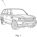
- a vehicle 100 in accordance with an embodiment of the present invention is described herein with reference to the accompanying Figures 1 and 2 .
- the vehicle 100 comprises a control system 200.
- the vehicle further comprises a first sensor arrangement 210 and one or more additional sensor arrangements 220.
- the first sensor arrangement 210 and each additional sensor arrangement 220 are communicatively coupled to the control system 200.
- a wired or wireless connection between the sensor arrangements 210, 220 and the control system 200 may be provided to effect this communication.
- the sensor arrangements 210, 220 are grouped by orientation. However, control and power of sensors within each arrangement may be grouped alternatively. For example, within each sensor arrangement 210, 220 there may be provided one or more primary sensors of a primary sensor system and one or more secondary sensors of a secondary sensor system.
- the vehicle also comprises primary power supply 212 and one or more secondary power supplies 222.
- the primary power supply 212 is coupled to the sensors within the sensor arrangements 210, 220 that are part of the primary sensor system in order to provide power thereto.
- the one or more secondary power supplies 222 are coupled to the sensors within the sensor arrangements 210, 220 that are part of the secondary sensor system in order to provide power thereto. Since sensors the secondary sensor system are not dependent upon the same power supply as the primary sensor system, the chance of simultaneous power loss to both sensor systems is reduced.
- the control system 200 may be implemented using one or more processors.
- the control system may also comprise data storage.
- the control system 200 of the illustrated embodiments comprises interfaces 202, 204 to facilitate communication with the sensors of the primary sensor system and those of the secondary sensor system. As such, there are provided separate network connections for the sensors of the primary sensor system and sensors of the secondary sensor system. This can reduce the risk of simultaneous loss of data from both sensor systems to the control system 200.
- the control system 200 is configured to receive data from the sensor arrangements 210, 220 and process this to determine a localisation, such as a lateral localisation, of the vehicle 100.
- a localisation such as a lateral localisation
- the control system 200 may determine a lateral position of the vehicle 100 on a roadway.
- the control system 200 may utilise the output of this determination to control the vehicle 100 and/or to provide feedback to an occupant of the vehicle 100 through a human machine interface (HMI).
- HMI human machine interface
- the control system 200 may also provide information to one or more remote servers where appropriate.
- each sensor arrangement 210, 220 comprises at least a camera and one or more lidar sensors.
- the cameras of each sensor arrangement may, for example, for the sensors of the primary sensors system while the lidar sensors may form the sensors of the secondary sensory system.
- the first sensor arrangement 210 has a first orientation.
- this orientation is forward facing. That is to say, the sensors of the first sensor arrangement 210 are forward facing. Accordingly, they have a field of view centred on the usual direction of travel of the vehicle.
- Each additional sensor arrangement 220 has an orientation different to the first orientation. Accordingly, the orientations of the sensors in the additional sensor arrangements 220 are different to those of the first sensor arrangement 210.
- the illustrated additional sensor arrangement 220 is rearward facing, and thus the fields of view of the sensors of this additional sensor arrangement 220 is centred opposite to the usual direction of travel of the vehicle 100.
- each additional sensor arrangement 220 is substantially different to that of the first orientation of the first sensor arrangement 210.
- the orientation of each additional sensor arrangement 220 may at an angle of at least 45 degrees, preferably at least 90 degrees to the first orientation. This may ensure that sensors of the additional sensor arrangements 220 have a substantially different field of view to equivalent sensors of the first sensor arrangement 210.
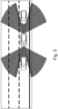
- FIG. 3 and 4 shows a side view and plan view of the fields of view of the sensors within the forward facing first sensor arrangement 210 and rear-facing additional sensor arrangement 220 of the vehicle 100 illustrated in Figure 2 .
- Each sensor arrangement comprises a camera sensor mounted near the top of the vehicle, and a lidar sensor mounted in the bumper. Spatially displacing the sensors can reduce the probability of both sensors being obstructed or damaged in the same instance.
- the lidar sensor may have a wider field of view than the camera sensor. As illustrated in Figure 5 , this may be of particular benefit where other vehicles are in close proximity to host vehicle 100 as, for example, lane marking may be obscured for the camera sensors.
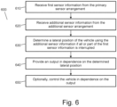
- Method 600 is a method for estimating a lateral position of the host vehicle 100, the host vehicle comprising a first sensor arrangement 210 disposed at a first orientation relative to the host vehicle 100 and at least one additional sensor arrangement 220, each additional sensor arrangement 220 being disposed at an orientation relative to the host vehicle 100 that is different to the first orientation.
- the method comprises receiving 610 first sensor information from the primary sensor arrangement 210 and receiving 620 additional sensor information from the additional sensor arrangement 220.
- the control system determines 630 a lateral position of the vehicle 100 from this sensor information, in particular modifying an estimate of lateral position on a roadway that would have been derivable from the first sensor information alone by utilising the additional sensor information. Where all or part of the first sensor information is unavailable (for example, due to failure of one or more sensors within the first sensor arrangement 210) the lateral position may be determined from the additional sensor information together with any remaining sensor information from the first sensor arrangement 210.
- the method then comprises the control system 200 providing 640 an output in dependence on the determined lateral position.
- the method may further comprise controlling 650 the vehicle 100 in dependence on the output.
- the method may alternatively or additional comprise providing feedback to an occupant of the vehicle 100 through a human machine interface (HMI) in dependence on the output.
- HMI human machine interface
- the control system 200 may also provide information to one or more remote servers where appropriate.
- the control system 200 In order to determine the lateral position of the vehicle relative to the roadway, the control system 200 continuously determines the curvature of lane markings visible to the sensor arrangements 210, 220. As can be seen form Figure 7 , even in circumstances in which all sensors are functioning normally it may be that there is limited information that can be derived regarding the lane markings from the forward facing first sensor arrangement 210. To alleviate this limitation on an estimate of curvature derived solely from the first sensor information, the lane information from the additional sensor information is used in conjunction with the first sensor information in order to estimate the curvature of the lanes. That is, by using the additional sensor information there may be a greater number of points available for use with a line fitting algorithm.
- the support of the additional sensor arrangement together with the first sensor arrangement can increase the accuracy and robustness of lateral localisation and lane detection in a number of scenarios. For example, by improving the lane curvature estimate as identified above or by improving lateral localisation when information is obscured, such as when: road lines are faded or obscured due to weather conditions, the field of view (FoV) of the front sensors is partially or fully obstructed or lane markings would otherwise be obscured from the front sensors due to traffic.
- the use of the additional sensor information can also provide further pertinent detail that might not be otherwise available, such as in lane merging situations (see, for example, Figure 9 ).
- the use of additional sensor information can allow lateral localisation where all or part of the first sensor information is interrupted. For example, it may allow the vehicle to maintain lane position in the case of: blinding of front sensors; software or hardware failure of one or more front sensors; network failure to one or more front sensors; the loss of power to one or more of the front sensors; damage to the front sensor arrangement 210 due to road debris or other impacts; limitations on the front sensors due other environmental conditions and/or dirt build up on the sensors.
- control system 200 may predict the curvature of the lane ahead of the vehicle by fitting a curve to lane points detected by each additional sensor arrangement 220 and may therefore estimate the lane curvature ahead. Since the additional sensor arrangement 220 remains operational, the control system continues to have real time information rather than relying on historical data.
- control system may also have access to map information and information from a positioning system such as GPS.
- FIGS 8 and 9 illustrate the use of further additional sensor arrangements.
- the further additional sensor arrangements are side-facing (i.e. face left and right of the vehicle's usual direction of travel).
- the side-facing additional sensor arrangements could be used as an alternative.
- Figure 8 illustrates the multiple obstacles may block the fields of view of the first sensor arrangement, while a far more detailed understanding of the environment may be obtained from side- and rear-facing sensors in this circumstance.
- Figure 9 further illustrate that such additional sensor arrangements may be of particular use in complex lane scenarios, such as during (forced) lane mergers or similar. Again, the use of additional sensor information may improve a lateral localisation that would be possible from the primary sensor arrangement alone.
Landscapes
- Engineering & Computer Science (AREA)
- Automation & Control Theory (AREA)
- Mechanical Engineering (AREA)
- Transportation (AREA)
- Physics & Mathematics (AREA)
- Human Computer Interaction (AREA)
- General Physics & Mathematics (AREA)
- Multimedia (AREA)
- Mathematical Physics (AREA)
- Theoretical Computer Science (AREA)
- Computer Networks & Wireless Communication (AREA)
- Electromagnetism (AREA)
- Radar, Positioning & Navigation (AREA)
- Remote Sensing (AREA)
- Traffic Control Systems (AREA)
- Control Of Driving Devices And Active Controlling Of Vehicle (AREA)
Description
- The present invention relates to vehicle localisation, particularly to lateral vehicle localisation.
- Vehicle localisation relates to the identification of a current location of a vehicle and finds particular utility in fields such as assisted or autonomous vehicle control. It can be of particular import to identify the lateral position of the vehicle relative to the roadway it is traversing. In some scenarios, this lateral localisation may include lane detection, localisation within a lane and lane number assignment processes.
- Some existing approaches to the challenge of lateral localisation use one or more forward-facing sensors in order to detect lane markings or vehicles and localise the host vehicle within its lane and within the road by assigning lane number to it. This data is then used to calculate the path of the host/ego vehicle.
- There are a number of scenarios in which the information available from such sensors can be degraded. This loss of information may be the result of sensor failure or some aspect of external conditions. For example, lane markings in front of the host vehicle may have faded or be blocked by other objects (such as vehicles in front of the host vehicle). One approach in such circumstances is to estimate a relevant localisation attribute (such as lane curvature) from past data, but this may imply a time delay as such a history is generated. Alternatively, the host vehicle may choose to follow the path of the preceding vehicle, but this may propagate errors in control of the preceding vehicle to the host vehicle.
- In circumstances in which the forward-facing sensors provide no data at all, the problem can be even more acute. Sensors may be effectively blinded (for example, cameras due to sunlight or lidar sensors due to dirt buildup) or may be subject to technical failure (in sensor itself or in the power supply).
- It is an aim of the present invention to address one or more of the disadvantages associated with the prior art.
- A lane keeping system is described in
US2017/355366 . A sensor management technique is described in « Adaptive Error and Sensor Management for Autonomous Vehicles: Model-Based Approach and Run-Time System", FRTUNIKJ JELENA ET AL. - Aspects and embodiments of the invention provide a vehicle as claimed in the appended claims.
- One or more embodiments of the invention will now be described, by way of example only, with reference to the accompanying drawings, in which:
-
Figure 1 shows a vehicle in accordance with an embodiment of the invention; -
Figure 2 shows a schematic representation of the vehicle ofFigure 1 , illustrating elements utilised for localisation of the vehicle; -
Figure 3 illustrates exemplary vertical fields of view for sensors of the vehicle; -
Figure 4 illustrates exemplary horizontal fields of view for the sensors; -
Figure 5 illustrates fields of view on a roadway with other vehicles; -
Figure 6 shows a flow diagram of a method for estimating the lateral position of a host vehicle in accordance with an embodiment of the invention; -
Figure 7 illustrates fields of view on a curved roadway; -
Figure 8 illustrates an alternative example set of horizontal fields of view; and -
Figure 9 illustrates the fields of view ofFigure 8 in a scenario in which lanes of a roadway merge. - A
vehicle 100 in accordance with an embodiment of the present invention is described herein with reference to the accompanyingFigures 1 and2 . - With reference to
Figure 2 , thevehicle 100 comprises acontrol system 200. The vehicle further comprises afirst sensor arrangement 210 and one or moreadditional sensor arrangements 220. Thefirst sensor arrangement 210 and eachadditional sensor arrangement 220 are communicatively coupled to thecontrol system 200. A wired or wireless connection between thesensor arrangements control system 200 may be provided to effect this communication. - As described, the
sensor arrangements sensor arrangement - The vehicle also comprises
primary power supply 212 and one or moresecondary power supplies 222. Theprimary power supply 212 is coupled to the sensors within thesensor arrangements secondary power supplies 222 are coupled to the sensors within thesensor arrangements - The
control system 200 may be implemented using one or more processors. The control system may also comprise data storage. Thecontrol system 200 of the illustrated embodiments comprisesinterfaces control system 200. - The
control system 200 is configured to receive data from thesensor arrangements vehicle 100. In particular, thecontrol system 200 may determine a lateral position of thevehicle 100 on a roadway. Thecontrol system 200 may utilise the output of this determination to control thevehicle 100 and/or to provide feedback to an occupant of thevehicle 100 through a human machine interface (HMI). Thecontrol system 200 may also provide information to one or more remote servers where appropriate. - In the embodiment illustrated in
Figure 2 , thefirst sensor arrangement 210 and each additional sensor arrangement each comprise a plurality of sensors. In particular, eachsensor arrangement - The
first sensor arrangement 210 has a first orientation. In the preferred embodiment, this orientation is forward facing. That is to say, the sensors of thefirst sensor arrangement 210 are forward facing. Accordingly, they have a field of view centred on the usual direction of travel of the vehicle. - Each
additional sensor arrangement 220 has an orientation different to the first orientation. Accordingly, the orientations of the sensors in theadditional sensor arrangements 220 are different to those of thefirst sensor arrangement 210. InFigure 2 , for example, the illustratedadditional sensor arrangement 220 is rearward facing, and thus the fields of view of the sensors of thisadditional sensor arrangement 220 is centred opposite to the usual direction of travel of thevehicle 100. - Alternative relative orientations of the
sensor arrangements additional sensor arrangement 220 is substantially different to that of the first orientation of thefirst sensor arrangement 210. For example, the orientation of eachadditional sensor arrangement 220 may at an angle of at least 45 degrees, preferably at least 90 degrees to the first orientation. This may ensure that sensors of theadditional sensor arrangements 220 have a substantially different field of view to equivalent sensors of thefirst sensor arrangement 210. - This can further understood with reference to
Figures 3 and 4 , which shows a side view and plan view of the fields of view of the sensors within the forward facingfirst sensor arrangement 210 and rear-facingadditional sensor arrangement 220 of thevehicle 100 illustrated inFigure 2 . Each sensor arrangement comprises a camera sensor mounted near the top of the vehicle, and a lidar sensor mounted in the bumper. Spatially displacing the sensors can reduce the probability of both sensors being obstructed or damaged in the same instance. As can be seen fromFigure 4 , for example, the lidar sensor may have a wider field of view than the camera sensor. As illustrated inFigure 5 , this may be of particular benefit where other vehicles are in close proximity to hostvehicle 100 as, for example, lane marking may be obscured for the camera sensors. - In use, the
control system 200 may perform themethod 600 illustrated inFigure 6 .Method 600 is a method for estimating a lateral position of thehost vehicle 100, the host vehicle comprising afirst sensor arrangement 210 disposed at a first orientation relative to thehost vehicle 100 and at least oneadditional sensor arrangement 220, eachadditional sensor arrangement 220 being disposed at an orientation relative to thehost vehicle 100 that is different to the first orientation. - The method comprises receiving 610 first sensor information from the
primary sensor arrangement 210 and receiving 620 additional sensor information from theadditional sensor arrangement 220. The control system then determines 630 a lateral position of thevehicle 100 from this sensor information, in particular modifying an estimate of lateral position on a roadway that would have been derivable from the first sensor information alone by utilising the additional sensor information. Where all or part of the first sensor information is unavailable (for example, due to failure of one or more sensors within the first sensor arrangement 210) the lateral position may be determined from the additional sensor information together with any remaining sensor information from thefirst sensor arrangement 210. The method then comprises thecontrol system 200 providing 640 an output in dependence on the determined lateral position. Optionally, the method may further comprise controlling 650 thevehicle 100 in dependence on the output. As noted previously, the method may alternatively or additional comprise providing feedback to an occupant of thevehicle 100 through a human machine interface (HMI) in dependence on the output. Thecontrol system 200 may also provide information to one or more remote servers where appropriate. - In order to determine the lateral position of the vehicle relative to the roadway, the
control system 200 continuously determines the curvature of lane markings visible to thesensor arrangements Figure 7 , even in circumstances in which all sensors are functioning normally it may be that there is limited information that can be derived regarding the lane markings from the forward facingfirst sensor arrangement 210. To alleviate this limitation on an estimate of curvature derived solely from the first sensor information, the lane information from the additional sensor information is used in conjunction with the first sensor information in order to estimate the curvature of the lanes. That is, by using the additional sensor information there may be a greater number of points available for use with a line fitting algorithm. - The support of the additional sensor arrangement together with the first sensor arrangement can increase the accuracy and robustness of lateral localisation and lane detection in a number of scenarios. For example, by improving the lane curvature estimate as identified above or by improving lateral localisation when information is obscured, such as when: road lines are faded or obscured due to weather conditions, the field of view (FoV) of the front sensors is partially or fully obstructed or lane markings would otherwise be obscured from the front sensors due to traffic. The use of the additional sensor information can also provide further pertinent detail that might not be otherwise available, such as in lane merging situations (see, for example,
Figure 9 ). - As well as working in conjunction with the first sensor information where available, the use of additional sensor information can allow lateral localisation where all or part of the first sensor information is interrupted. For example, it may allow the vehicle to maintain lane position in the case of: blinding of front sensors; software or hardware failure of one or more front sensors; network failure to one or more front sensors; the loss of power to one or more of the front sensors; damage to the
front sensor arrangement 210 due to road debris or other impacts; limitations on the front sensors due other environmental conditions and/or dirt build up on the sensors. - When all or part of the information from the first sensor arrangement is lost, the
control system 200 may predict the curvature of the lane ahead of the vehicle by fitting a curve to lane points detected by eachadditional sensor arrangement 220 and may therefore estimate the lane curvature ahead. Since theadditional sensor arrangement 220 remains operational, the control system continues to have real time information rather than relying on historical data. - To supplement the information from
first sensor arrangement 210 and eachadditional sensor arrangement 220, the control system may also have access to map information and information from a positioning system such as GPS. -
Figures 8 and9 illustrate the use of further additional sensor arrangements. In this case, the further additional sensor arrangements are side-facing (i.e. face left and right of the vehicle's usual direction of travel). Although shown in addition to the rear-facingadditional sensor arrangement 220, the side-facing additional sensor arrangements could be used as an alternative. -
Figure 8 illustrates the multiple obstacles may block the fields of view of the first sensor arrangement, while a far more detailed understanding of the environment may be obtained from side- and rear-facing sensors in this circumstance.Figure 9 further illustrate that such additional sensor arrangements may be of particular use in complex lane scenarios, such as during (forced) lane mergers or similar. Again, the use of additional sensor information may improve a lateral localisation that would be possible from the primary sensor arrangement alone. - It will be appreciated that various changes and modifications can be made to the present invention without departing from the scope of the present invention as defined by the claims.
Claims (14)
- A vehicle (100) comprising a control system (200), the vehicle comprising a first sensor arrangement (210) disposed at a first orientation relative to the host vehicle and at least one secondary sensor arrangement (220), each additional sensor arrangement being disposed at an orientation relative to the host vehicle that is different to the first orientation, the control system having one or more controllers configured to:receive (610) first sensor information from the first sensor arrangement (210);receive (620) secondary sensor information from each additional sensor arrangement (220);determine (630) a lateral position of the vehicle relative to a roadway using the additional sensor information if all or part of the first sensor information is interrupted; andprovide (640) an output in dependence on the determined lateral position;wherein each sensor arrangement comprises a primary sensor which is part of a primary sensor system and a secondary sensor which is part of a secondary sensor system; andwherein independent power supplies (212. 222) are provided for primary and secondary sensors within each sensor arrangement.
- The vehicle of claim 1 wherein the one or more controllers collectively comprise:at least one electronic processor having an electrical input for receiving signals; and,at least one electronic memory device electrically coupled to the at least one electronic processor and having instructions stored therein;and wherein the at least one electronic processor is configured to access the at least one memory device and execute the instructions thereon so as to cause the control system to:receive first sensor information from the first sensor arrangement (210);receive secondary sensor information from each additional sensor arrangement (220);determine a lateral position of the vehicle relative to a roadway using the additional sensor information if all or part of the first sensor information is interrupted; andprovide an output in dependence on the determined lateral position.
- The vehicle according to claim 1 or claim 2, wherein the first sensor arrangement (210) comprises one or more sensors aligned with the first orientation and each additional sensor arrangement (230) comprises one or more sensors aligned at an orientation different to the first orientation.
- The vehicle according to any one of the preceding claims, wherein the control system is further configured to determine the lateral position of the vehicle relative to the roadway from the additional sensor information in conjunction with the first sensor information if the first sensor information is available.
- The vehicle according to any one of the preceding claims, wherein at least one additional sensor arrangement (220) is disposed at an orientation opposite to the first orientation
- The vehicle according to any one of the preceding claims, wherein the first orientation is forward facing relative to the host vehicle.
- The vehicle according to any one of the preceding claims, wherein the output of the control system is a control output for controlling a position of the host vehicle.
- The vehicle according to any one of the preceding claims, comprising at least one additional sensor arrangement that is is leftward facing relative to the vehicle and at least one additional sensor arrangement that is rightward facing relative to the vehicle.
- The vehicle according to any one of the preceding claims, wherein the control system is configured to determine a position of the host vehicle relative to one or more lanes of the roadway.
- The vehicle according to any one of the preceding claims, wherein the control system is configured to determine the lateral position of the vehicle by estimating curvature of one or more environmental elements.
- The vehicle according to claim 10, wherein the one or more environmental elements comprise lane markings.
- The vehicle according to any one of the preceding claims, wherein the control system is further configured to receive map information describing the environment of the host vehicle, and wherein the control system is configured to determine the lateral position of the vehicle on a route in dependence on the map information.
- The vehicle according to any preceding claim, wherein the control system comprises a plurality of interface elements (202, 204), each interface element being communicatively coupled to primary and secondary sensors within each sensor arrangement.
- The vehicle according to any preceding claim, wherein a primary power supply (212) is provided to power the primary sensor of both the first and each additional sensor arrangement, and a secondary power supply (222) is provided to power the secondary sensor of both the first and each additional sensor arrangement.
Applications Claiming Priority (2)
| Application Number | Priority Date | Filing Date | Title |
|---|---|---|---|
| GB1904966.7A GB2583698B (en) | 2019-04-08 | 2019-04-08 | Vehicle localisation |
| PCT/EP2020/059838 WO2020207996A1 (en) | 2019-04-08 | 2020-04-07 | Vehicle localisation |
Publications (2)
| Publication Number | Publication Date |
|---|---|
| EP3953228A1 EP3953228A1 (en) | 2022-02-16 |
| EP3953228B1 true EP3953228B1 (en) | 2024-11-20 |
Family
ID=66809559
Family Applications (1)
| Application Number | Title | Priority Date | Filing Date |
|---|---|---|---|
| EP20717186.9A Active EP3953228B1 (en) | 2019-04-08 | 2020-04-07 | Vehicle localisation |
Country Status (5)
| Country | Link |
|---|---|
| US (1) | US12054165B2 (en) |
| EP (1) | EP3953228B1 (en) |
| CN (1) | CN113795418B (en) |
| GB (1) | GB2583698B (en) |
| WO (1) | WO2020207996A1 (en) |
Families Citing this family (1)
| Publication number | Priority date | Publication date | Assignee | Title |
|---|---|---|---|---|
| JP7275636B2 (en) * | 2019-02-22 | 2023-05-18 | セイコーエプソン株式会社 | Automated Guided Vehicle System and Self-Position Estimation Method for Automated Guided Vehicle |
Family Cites Families (11)
| Publication number | Priority date | Publication date | Assignee | Title |
|---|---|---|---|---|
| US7400236B2 (en) * | 2005-10-21 | 2008-07-15 | Gm Global Technology Operations, Inc. | Vehicular lane monitoring system utilizing front and rear cameras |
| US9542846B2 (en) * | 2011-02-28 | 2017-01-10 | GM Global Technology Operations LLC | Redundant lane sensing systems for fault-tolerant vehicular lateral controller |
| US8798841B1 (en) * | 2013-03-14 | 2014-08-05 | GM Global Technology Operations LLC | System and method for improving sensor visibility of vehicle in autonomous driving mode |
| KR101588787B1 (en) * | 2013-12-02 | 2016-01-26 | 현대자동차 주식회사 | Method for determining lateral distance of forward vehicle and head up display system using the same |
| JP6032195B2 (en) * | 2013-12-26 | 2016-11-24 | トヨタ自動車株式会社 | Sensor abnormality detection device |
| JP2017165296A (en) * | 2016-03-17 | 2017-09-21 | 株式会社日立製作所 | Automatic operation control system |
| US9840253B1 (en) * | 2016-06-14 | 2017-12-12 | Delphi Technologies, Inc. | Lane keeping system for autonomous vehicle during camera drop-outs |
| US10210406B2 (en) * | 2016-08-19 | 2019-02-19 | Dura Operating, Llc | System and method of simultaneously generating a multiple lane map and localizing a vehicle in the generated map |
| US10434883B2 (en) * | 2016-09-27 | 2019-10-08 | Ford Global Technologies, Llc | Safety critical systems control in autonomous vehicles |
| DE102017204603B4 (en) | 2017-03-20 | 2023-10-26 | Continental Autonomous Mobility Germany GmbH | Vehicle control system and method for controlling a vehicle |
| KR102374916B1 (en) * | 2017-09-29 | 2022-03-16 | 주식회사 만도모빌리티솔루션즈 | Apparatus and Method for Controlling Lane-Keeping |
-
2019
- 2019-04-08 GB GB1904966.7A patent/GB2583698B/en not_active Expired - Fee Related
-
2020
- 2020-04-07 US US17/602,566 patent/US12054165B2/en active Active
- 2020-04-07 WO PCT/EP2020/059838 patent/WO2020207996A1/en not_active Ceased
- 2020-04-07 CN CN202080033295.6A patent/CN113795418B/en active Active
- 2020-04-07 EP EP20717186.9A patent/EP3953228B1/en active Active
Also Published As
| Publication number | Publication date |
|---|---|
| WO2020207996A1 (en) | 2020-10-15 |
| GB2583698B (en) | 2021-10-06 |
| EP3953228A1 (en) | 2022-02-16 |
| GB201904966D0 (en) | 2019-05-22 |
| CN113795418A (en) | 2021-12-14 |
| US12054165B2 (en) | 2024-08-06 |
| GB2583698A (en) | 2020-11-11 |
| CN113795418B (en) | 2024-07-23 |
| US20220185300A1 (en) | 2022-06-16 |
Similar Documents
| Publication | Publication Date | Title |
|---|---|---|
| US9840253B1 (en) | Lane keeping system for autonomous vehicle during camera drop-outs | |
| US12570293B2 (en) | Method and device for multi-sensor data fusion for automated and autonomous vehicles | |
| EP3380392B1 (en) | Auto docking method for application in heavy trucks | |
| CN110440811B (en) | A universal autonomous navigation control method, device and equipment terminal | |
| US20180283892A1 (en) | Automated image labeling for vehicles based on maps | |
| US20180099667A1 (en) | Vehicle control device | |
| CN110796063A (en) | Method, device, equipment, storage medium and vehicle for detecting parking space | |
| CN115237124B (en) | Methods and devices for determining travel path boundaries, vehicles, storage media, and terminals | |
| US11663808B2 (en) | Distance estimating device and storage medium storing computer program for distance estimation | |
| CN110969059A (en) | Lane line recognition method and system | |
| US10970870B2 (en) | Object detection apparatus | |
| US12351209B2 (en) | Method and device for operating a robot with improved object detection | |
| WO2015098344A1 (en) | Mining work machine | |
| CN113885525A (en) | A path planning method, system, vehicle and storage medium for self-driving vehicles to get out of trouble | |
| Han et al. | Robust ego-motion estimation and map matching technique for autonomous vehicle localization with high definition digital map | |
| KR20210070515A (en) | System and method for controlling driving lane keeping | |
| CN117184060A (en) | Track correction method and device, unmanned vehicle and storage medium | |
| EP3953228B1 (en) | Vehicle localisation | |
| JP2025072732A (en) | Autonomous Driving System | |
| KR20240033471A (en) | Method and system for sensor fusion in vehicle | |
| JP7326429B2 (en) | How to select the sensor image interval | |
| US12529774B2 (en) | Online LIDAR-to-ground alignment | |
| CN117761675A (en) | Radar-based environmental detection system for motor vehicles | |
| KR20230158335A (en) | Vehicle and control method thereof | |
| KR102518552B1 (en) | Apparatus for controlling driving of platooning vehicle, system having the same and method thereof |
Legal Events
| Date | Code | Title | Description |
|---|---|---|---|
| STAA | Information on the status of an ep patent application or granted ep patent |
Free format text: STATUS: UNKNOWN |
|
| STAA | Information on the status of an ep patent application or granted ep patent |
Free format text: STATUS: THE INTERNATIONAL PUBLICATION HAS BEEN MADE |
|
| PUAI | Public reference made under article 153(3) epc to a published international application that has entered the european phase |
Free format text: ORIGINAL CODE: 0009012 |
|
| STAA | Information on the status of an ep patent application or granted ep patent |
Free format text: STATUS: REQUEST FOR EXAMINATION WAS MADE |
|
| 17P | Request for examination filed |
Effective date: 20211108 |
|
| AK | Designated contracting states |
Kind code of ref document: A1 Designated state(s): AL AT BE BG CH CY CZ DE DK EE ES FI FR GB GR HR HU IE IS IT LI LT LU LV MC MK MT NL NO PL PT RO RS SE SI SK SM TR |
|
| DAV | Request for validation of the european patent (deleted) | ||
| DAX | Request for extension of the european patent (deleted) | ||
| P01 | Opt-out of the competence of the unified patent court (upc) registered |
Effective date: 20230527 |
|
| STAA | Information on the status of an ep patent application or granted ep patent |
Free format text: STATUS: EXAMINATION IS IN PROGRESS |
|
| 17Q | First examination report despatched |
Effective date: 20231129 |
|
| GRAP | Despatch of communication of intention to grant a patent |
Free format text: ORIGINAL CODE: EPIDOSNIGR1 |
|
| STAA | Information on the status of an ep patent application or granted ep patent |
Free format text: STATUS: GRANT OF PATENT IS INTENDED |
|
| INTG | Intention to grant announced |
Effective date: 20240624 |
|
| GRAS | Grant fee paid |
Free format text: ORIGINAL CODE: EPIDOSNIGR3 |
|
| GRAA | (expected) grant |
Free format text: ORIGINAL CODE: 0009210 |
|
| STAA | Information on the status of an ep patent application or granted ep patent |
Free format text: STATUS: THE PATENT HAS BEEN GRANTED |
|
| AK | Designated contracting states |
Kind code of ref document: B1 Designated state(s): AL AT BE BG CH CY CZ DE DK EE ES FI FR GB GR HR HU IE IS IT LI LT LU LV MC MK MT NL NO PL PT RO RS SE SI SK SM TR |
|
| REG | Reference to a national code |
Ref country code: GB Ref legal event code: FG4D |
|
| REG | Reference to a national code |
Ref country code: CH Ref legal event code: EP |
|
| REG | Reference to a national code |
Ref country code: DE Ref legal event code: R096 Ref document number: 602020041623 Country of ref document: DE |
|
| REG | Reference to a national code |
Ref country code: IE Ref legal event code: FG4D |
|
| REG | Reference to a national code |
Ref country code: LT Ref legal event code: MG9D |
|
| REG | Reference to a national code |
Ref country code: NL Ref legal event code: MP Effective date: 20241120 |
|
| PG25 | Lapsed in a contracting state [announced via postgrant information from national office to epo] |
Ref country code: HR Free format text: LAPSE BECAUSE OF FAILURE TO SUBMIT A TRANSLATION OF THE DESCRIPTION OR TO PAY THE FEE WITHIN THE PRESCRIBED TIME-LIMIT Effective date: 20241120 Ref country code: PT Free format text: LAPSE BECAUSE OF FAILURE TO SUBMIT A TRANSLATION OF THE DESCRIPTION OR TO PAY THE FEE WITHIN THE PRESCRIBED TIME-LIMIT Effective date: 20250320 Ref country code: IS Free format text: LAPSE BECAUSE OF FAILURE TO SUBMIT A TRANSLATION OF THE DESCRIPTION OR TO PAY THE FEE WITHIN THE PRESCRIBED TIME-LIMIT Effective date: 20250320 |
|
| PG25 | Lapsed in a contracting state [announced via postgrant information from national office to epo] |
Ref country code: FI Free format text: LAPSE BECAUSE OF FAILURE TO SUBMIT A TRANSLATION OF THE DESCRIPTION OR TO PAY THE FEE WITHIN THE PRESCRIBED TIME-LIMIT Effective date: 20241120 Ref country code: NL Free format text: LAPSE BECAUSE OF FAILURE TO SUBMIT A TRANSLATION OF THE DESCRIPTION OR TO PAY THE FEE WITHIN THE PRESCRIBED TIME-LIMIT Effective date: 20241120 |
|
| REG | Reference to a national code |
Ref country code: AT Ref legal event code: MK05 Ref document number: 1743341 Country of ref document: AT Kind code of ref document: T Effective date: 20241120 |
|
| PG25 | Lapsed in a contracting state [announced via postgrant information from national office to epo] |
Ref country code: BG Free format text: LAPSE BECAUSE OF FAILURE TO SUBMIT A TRANSLATION OF THE DESCRIPTION OR TO PAY THE FEE WITHIN THE PRESCRIBED TIME-LIMIT Effective date: 20241120 |
|
| PG25 | Lapsed in a contracting state [announced via postgrant information from national office to epo] |
Ref country code: ES Free format text: LAPSE BECAUSE OF FAILURE TO SUBMIT A TRANSLATION OF THE DESCRIPTION OR TO PAY THE FEE WITHIN THE PRESCRIBED TIME-LIMIT Effective date: 20241120 |
|
| PG25 | Lapsed in a contracting state [announced via postgrant information from national office to epo] |
Ref country code: NO Free format text: LAPSE BECAUSE OF FAILURE TO SUBMIT A TRANSLATION OF THE DESCRIPTION OR TO PAY THE FEE WITHIN THE PRESCRIBED TIME-LIMIT Effective date: 20250220 |
|
| PG25 | Lapsed in a contracting state [announced via postgrant information from national office to epo] |
Ref country code: AT Free format text: LAPSE BECAUSE OF FAILURE TO SUBMIT A TRANSLATION OF THE DESCRIPTION OR TO PAY THE FEE WITHIN THE PRESCRIBED TIME-LIMIT Effective date: 20241120 Ref country code: GR Free format text: LAPSE BECAUSE OF FAILURE TO SUBMIT A TRANSLATION OF THE DESCRIPTION OR TO PAY THE FEE WITHIN THE PRESCRIBED TIME-LIMIT Effective date: 20250221 Ref country code: LV Free format text: LAPSE BECAUSE OF FAILURE TO SUBMIT A TRANSLATION OF THE DESCRIPTION OR TO PAY THE FEE WITHIN THE PRESCRIBED TIME-LIMIT Effective date: 20241120 |
|
| PG25 | Lapsed in a contracting state [announced via postgrant information from national office to epo] |
Ref country code: PL Free format text: LAPSE BECAUSE OF FAILURE TO SUBMIT A TRANSLATION OF THE DESCRIPTION OR TO PAY THE FEE WITHIN THE PRESCRIBED TIME-LIMIT Effective date: 20241120 |
|
| PG25 | Lapsed in a contracting state [announced via postgrant information from national office to epo] |
Ref country code: RS Free format text: LAPSE BECAUSE OF FAILURE TO SUBMIT A TRANSLATION OF THE DESCRIPTION OR TO PAY THE FEE WITHIN THE PRESCRIBED TIME-LIMIT Effective date: 20250220 |
|
| PG25 | Lapsed in a contracting state [announced via postgrant information from national office to epo] |
Ref country code: SM Free format text: LAPSE BECAUSE OF FAILURE TO SUBMIT A TRANSLATION OF THE DESCRIPTION OR TO PAY THE FEE WITHIN THE PRESCRIBED TIME-LIMIT Effective date: 20241120 |
|
| PGFP | Annual fee paid to national office [announced via postgrant information from national office to epo] |
Ref country code: DE Payment date: 20250422 Year of fee payment: 6 |
|
| PG25 | Lapsed in a contracting state [announced via postgrant information from national office to epo] |
Ref country code: DK Free format text: LAPSE BECAUSE OF FAILURE TO SUBMIT A TRANSLATION OF THE DESCRIPTION OR TO PAY THE FEE WITHIN THE PRESCRIBED TIME-LIMIT Effective date: 20241120 |
|
| PGFP | Annual fee paid to national office [announced via postgrant information from national office to epo] |
Ref country code: GB Payment date: 20250423 Year of fee payment: 6 |
|
| PG25 | Lapsed in a contracting state [announced via postgrant information from national office to epo] |
Ref country code: EE Free format text: LAPSE BECAUSE OF FAILURE TO SUBMIT A TRANSLATION OF THE DESCRIPTION OR TO PAY THE FEE WITHIN THE PRESCRIBED TIME-LIMIT Effective date: 20241120 |
|
| PGFP | Annual fee paid to national office [announced via postgrant information from national office to epo] |
Ref country code: FR Payment date: 20250425 Year of fee payment: 6 |
|
| PG25 | Lapsed in a contracting state [announced via postgrant information from national office to epo] |
Ref country code: RO Free format text: LAPSE BECAUSE OF FAILURE TO SUBMIT A TRANSLATION OF THE DESCRIPTION OR TO PAY THE FEE WITHIN THE PRESCRIBED TIME-LIMIT Effective date: 20241120 |
|
| PG25 | Lapsed in a contracting state [announced via postgrant information from national office to epo] |
Ref country code: SK Free format text: LAPSE BECAUSE OF FAILURE TO SUBMIT A TRANSLATION OF THE DESCRIPTION OR TO PAY THE FEE WITHIN THE PRESCRIBED TIME-LIMIT Effective date: 20241120 |
|
| PG25 | Lapsed in a contracting state [announced via postgrant information from national office to epo] |
Ref country code: CZ Free format text: LAPSE BECAUSE OF FAILURE TO SUBMIT A TRANSLATION OF THE DESCRIPTION OR TO PAY THE FEE WITHIN THE PRESCRIBED TIME-LIMIT Effective date: 20241120 |
|
| PG25 | Lapsed in a contracting state [announced via postgrant information from national office to epo] |
Ref country code: IT Free format text: LAPSE BECAUSE OF FAILURE TO SUBMIT A TRANSLATION OF THE DESCRIPTION OR TO PAY THE FEE WITHIN THE PRESCRIBED TIME-LIMIT Effective date: 20241120 |
|
| REG | Reference to a national code |
Ref country code: DE Ref legal event code: R097 Ref document number: 602020041623 Country of ref document: DE |
|
| PG25 | Lapsed in a contracting state [announced via postgrant information from national office to epo] |
Ref country code: SE Free format text: LAPSE BECAUSE OF FAILURE TO SUBMIT A TRANSLATION OF THE DESCRIPTION OR TO PAY THE FEE WITHIN THE PRESCRIBED TIME-LIMIT Effective date: 20241120 |
|
| PLBE | No opposition filed within time limit |
Free format text: ORIGINAL CODE: 0009261 |
|
| STAA | Information on the status of an ep patent application or granted ep patent |
Free format text: STATUS: NO OPPOSITION FILED WITHIN TIME LIMIT |
|
| 26N | No opposition filed |
Effective date: 20250821 |
|
| REG | Reference to a national code |
Ref country code: CH Ref legal event code: H13 Free format text: ST27 STATUS EVENT CODE: U-0-0-H10-H13 (AS PROVIDED BY THE NATIONAL OFFICE) Effective date: 20251125 |
|
| PG25 | Lapsed in a contracting state [announced via postgrant information from national office to epo] |
Ref country code: LU Free format text: LAPSE BECAUSE OF NON-PAYMENT OF DUE FEES Effective date: 20250407 |
|
| PG25 | Lapsed in a contracting state [announced via postgrant information from national office to epo] |
Ref country code: MC Free format text: LAPSE BECAUSE OF FAILURE TO SUBMIT A TRANSLATION OF THE DESCRIPTION OR TO PAY THE FEE WITHIN THE PRESCRIBED TIME-LIMIT Effective date: 20241120 |
|
| REG | Reference to a national code |
Ref country code: BE Ref legal event code: MM Effective date: 20250430 |
|
| PG25 | Lapsed in a contracting state [announced via postgrant information from national office to epo] |
Ref country code: BE Free format text: LAPSE BECAUSE OF NON-PAYMENT OF DUE FEES Effective date: 20250430 |
|
| PG25 | Lapsed in a contracting state [announced via postgrant information from national office to epo] |
Ref country code: CH Free format text: LAPSE BECAUSE OF NON-PAYMENT OF DUE FEES Effective date: 20250430 |
|
| PG25 | Lapsed in a contracting state [announced via postgrant information from national office to epo] |
Ref country code: IE Free format text: LAPSE BECAUSE OF NON-PAYMENT OF DUE FEES Effective date: 20250407 |