EP3953027B1 - Intensive mixing tool for producing elastomer-based composites - Google Patents
Intensive mixing tool for producing elastomer-based composites Download PDFInfo
- Publication number
- EP3953027B1 EP3953027B1 EP20718303.9A EP20718303A EP3953027B1 EP 3953027 B1 EP3953027 B1 EP 3953027B1 EP 20718303 A EP20718303 A EP 20718303A EP 3953027 B1 EP3953027 B1 EP 3953027B1
- Authority
- EP
- European Patent Office
- Prior art keywords
- extent
- elastomer
- conduit
- mixing chamber
- emulsion
- Prior art date
- Legal status (The legal status is an assumption and is not a legal conclusion. Google has not performed a legal analysis and makes no representation as to the accuracy of the status listed.)
- Active
Links
Images




Classifications
-
- B—PERFORMING OPERATIONS; TRANSPORTING
- B29—WORKING OF PLASTICS; WORKING OF SUBSTANCES IN A PLASTIC STATE IN GENERAL
- B29B—PREPARATION OR PRETREATMENT OF THE MATERIAL TO BE SHAPED; MAKING GRANULES OR PREFORMS; RECOVERY OF PLASTICS OR OTHER CONSTITUENTS OF WASTE MATERIAL CONTAINING PLASTICS
- B29B7/00—Mixing; Kneading
- B29B7/80—Component parts, details or accessories; Auxiliary operations
- B29B7/88—Adding charges, i.e. additives
- B29B7/90—Fillers or reinforcements, e.g. fibres
-
- B—PERFORMING OPERATIONS; TRANSPORTING
- B01—PHYSICAL OR CHEMICAL PROCESSES OR APPARATUS IN GENERAL
- B01F—MIXING, e.g. DISSOLVING, EMULSIFYING OR DISPERSING
- B01F25/00—Flow mixers; Mixers for falling materials, e.g. solid particles
- B01F25/10—Mixing by creating a vortex flow, e.g. by tangential introduction of flow components
-
- B—PERFORMING OPERATIONS; TRANSPORTING
- B29—WORKING OF PLASTICS; WORKING OF SUBSTANCES IN A PLASTIC STATE IN GENERAL
- B29B—PREPARATION OR PRETREATMENT OF THE MATERIAL TO BE SHAPED; MAKING GRANULES OR PREFORMS; RECOVERY OF PLASTICS OR OTHER CONSTITUENTS OF WASTE MATERIAL CONTAINING PLASTICS
- B29B7/00—Mixing; Kneading
- B29B7/74—Mixing; Kneading using other mixers or combinations of mixers, e.g. of dissimilar mixers ; Plant
- B29B7/7476—Systems, i.e. flow charts or diagrams; Plants
- B29B7/7495—Systems, i.e. flow charts or diagrams; Plants for mixing rubber
-
- B—PERFORMING OPERATIONS; TRANSPORTING
- B29—WORKING OF PLASTICS; WORKING OF SUBSTANCES IN A PLASTIC STATE IN GENERAL
- B29B—PREPARATION OR PRETREATMENT OF THE MATERIAL TO BE SHAPED; MAKING GRANULES OR PREFORMS; RECOVERY OF PLASTICS OR OTHER CONSTITUENTS OF WASTE MATERIAL CONTAINING PLASTICS
- B29B7/00—Mixing; Kneading
- B29B7/74—Mixing; Kneading using other mixers or combinations of mixers, e.g. of dissimilar mixers ; Plant
- B29B7/76—Mixers with stream-impingement mixing head
- B29B7/7631—Parts; Accessories
- B29B7/7636—Construction of the feed orifices, bores, ports
Definitions
- the central body of the intensive mixing tool includes a recess defined within the central body that establishes fluid communication with the mixing chamber.
- the recess has a central axis that is coextensive with the central axes of the central body and the mixing chamber.
- the intensive mixing tool further comprises a closure disposed along a top surface of the central body and having a geometry that complements insertion of the closure therein.
- the intensive mixing tool 10 may include an optional closure 34 that permits full access to the mixing chamber 20 of the central body 14.
- the closure 34 is disposed along the top surface 14c t of the central body 14 and may be detachably affixed thereat.
- the closure 34 has a geometry that complements that of a recess 14d defined within the central body 14.
- the recess 14d has a central axis that is coextensive with the central axes of the central body 14 and the mixing chamber 20.
- the recess 14d establishes fluid communication with the mixing chamber 20 and facilitates the supply of one or more additives and/or other components thereto.
Landscapes
- Engineering & Computer Science (AREA)
- Mechanical Engineering (AREA)
- Chemical & Material Sciences (AREA)
- Chemical Kinetics & Catalysis (AREA)
- Processing And Handling Of Plastics And Other Materials For Molding In General (AREA)
- Processes Of Treating Macromolecular Substances (AREA)
Description
- The invention is directed to an apparatus and method for producing elastomer-based composites, and particularly the production of elastomer-filler masterbatches, that are destined for use in finished and semi-finished elastomeric rubber products such as tires.
- In the art of producing elastomer-based composites, the term "masterbatch" refers to an elastomer-based composite into which a filler (organic or inorganic) has been introduced. In some masterbatches, the filler is introduced with one or more optional additives to obtain desired properties in rubber products derived from the selected masterbatch (such properties including, but not limited to, high wear resistance, high durability and low hysteresis). The masterbatches are then used for the manufacture of reinforced diene rubber compositions, intended, for example, for the manufacture of tires or of semi-finished products for tires (including, but not limited to, profiled products such as treads and reinforcing plies).
- It is known to obtain a masterbatch by continuous liquid mixing. In such a case, in the realization of elastomeric composites, the passage of a liquid mixture (e.g., a mixture of an emulsion of elastomer and a slurry of charge or filler) to a viscoelastic solid is effected by coagulation (as used herein, the terms "charge" and "filler" are interchangeable). To obtain the optimum reinforcing properties conferred by a filler in a rubber composition, it is known that it is generally advisable for this filler to be present in the elastomer matrix in a final form which is both as finely divided as possible and as uniformly distributed as possible. Such conditions are realized only when this filler can be readily incorporated into the matrix during mixing with the elastomer and also readily de-agglomerated. Such filler must also be capable of being uniformly dispersed in this matrix.
- Various methods exist for producing elastomeric masterbatch composites.
US Patent No. 6,048,923 (the '923 Patent), for example, describes a process for continuously preparing a filled rubber masterbatch that consists in bringing into contact, in a mixing zone, a first liquid-phase flow and a second liquid-phase flow. The first flow is an elastomer emulsion, and the second flow is an aqueous suspension of filler particles. The second flow is introduced under very high pressure into the mixing zone in order to form a stream sufficiently energetic to entrain the first flow and substantially completely coagulate the elastomer with the filler particles. The filler particles that are used are particles of carbon black. - German Patent No
DE112016003169 discloses a device and method for producing masterbatch composites as per the preamble of claim 1, and is directed to methods of making silica elastomer composites and the composites formed thereby. Reference is also made to German Publication No.DE1493663 (directed to a process for continuous preparation of an alkali metal salt). - It is appreciated that carbon black, unlike silica, exhibits a natural affinity with natural rubber. Silica particles have a tendency to agglomerate in the elastomer matrix, thereby limiting the dispersion of the filler therein. Thus, silica requires a customized method for producing a masterbatch having valuable material properties. One such method is disclosed by
US Patent No. 10,000,612 - It has not heretofore been established that the implementation of an intensive mixing tool may be applied in the rubber mixing domain, particularly with respect to the coagulation of an elastomer emulsion with a suspension of solid filler. The majority of intensive mixing tools rely on turbulent mixing as an efficient mechanism for dispersing the solutions into sufficiently small volume elements (or "turbulent eddies"). The small size of these eddies enables fast diffusion of the reactants over very short distances. Intensive mixing tools of various designs that enable efficient turbulent mixing have been constructed, and these range from T- or Y-mixers to more complex geometries, such as multiple-jet tangential mixers. Tangential jet mixers provide an example of an intensive mixing tool in which high-intensity mixing of fluids attains an almost homogeneous composition of high supersaturation before the onset of agglomeration. In a tangential jet mixer, at least two reactants are introduced into the mixer as two streams in a diametrically opposed but offset manner. These mixers have the advantage of high throughout and an inexpensive setup, even for small volumes. Their effectiveness relies upon the need for the mixing time to be shorter than the mean residence time. Adjustment of the inlet jet velocity may be accomplished by changing the incoming flow rate or by changing an inner injection channel diameter while maintaining the same flow rate.
- The implementation of these mixers on fast reactive systems is established in several fields outside of the rubber-mixing domain.
US Publication No. 2014/0205522 , for example, discloses a process for producing a composition for use in catalysis, the composition being based on oxides of cerium, zirconium and at least one rare-earth metal other than cerium. A reactor of rapid mixer type (shown and described with reference toFIG. 1 of the publication) may be used that may be chosen from T-shaped or Y-shaped mixers, tangential-jet mixers, Hartridge-Roughton mixers or vortex mixers. - In order to obtain optimum reinforcing properties conferred by a filler in a tire tread, and thus a high wear resistance, it is generally advisable for this filler to be present in the elastomer material in a final form that is both as finely divided as possible and as homogeneously distributed as possible. To advance this distribution, the disclosed invention employs an intensive mixing tool in a heretofore unknown manner that assures advantageous mixing conditions between a filler in an aqueous medium and an elastomer emulsion, even when silica is selected as the filler.
- The invention provides a system for producing an elastomer-filler masterbatch as per the subject-matter of claim 1. The system comprises an elastomer emulsion stored in a liquid phase in an emulsion reservoir; a slurry solution stored in a liquid phase in a slurry reservoir; and an intensive mixing tool in fluid communication with each of the emulsion reservoir and the slurry reservoir. The intensive mixing tool has an intensive mixing unit with a central body of predetermined height that is coextensive with an inlet extent and an opposed outlet extent, the central body including an external quadrilateral surface and an annular inner wall surface that defines a generally cylindrical mixing chamber of predetermined cross-sectional diameter relative to a central axis of the mixing chamber and having a central axis that is coaxial with a central axis of the mixing body. The mixing chamber has a predetermined length that is coextensive with an inlet extent of the mixing chamber and an egress extent of an integral and generally cylindrical projection that depends normally from the outlet extent of the central body. The intensive mixing tool also has an injector inlet that extends normally from each of a pair of opposed side surfaces of the central body such that at least a pair of injection inlets are located symmetrically and in opposing manner relative to a central axis of the central body, each injector inlet including a supply conduit defined therein that establishes fluid communication between an injector ingress via which one of an elastomer emulsion and a slurry solution enter the mixing unit and a corresponding injection conduit in registry therewith, each injector inlet establishing fluid communication between one of an elastomer emulsion reservoir from which a predetermined volume of the emulsion is introduced as a continuous flow under pressure, and a slurry solution reservoir from which a predetermined volume of the slurry is introduced as a continuous flow under pressure such that simultaneous injection of the elastomer emulsion and the slurry solution into the mixing chamber forms a vortex therein.
- In some embodiments of the system, each supply conduit includes a generally cylindrical entry portion of predetermined length that feeds into a feed portion of the supply conduit with the feed portion having a generally frustoconical geometry with a predetermined extent that is coextensive with a base disposed adjacent the entry portion and a summit disposed adjacent a feeding extent of a corresponding injection conduit. A tapering wall of each feed portion is defined at a predetermined acute angle relative to a central axis of the supply conduit and the corresponding injection conduit. For such embodiments, each injection conduit includes a predetermined length that is coextensive with its feeding extent and an opposed delivery extent that delivers a continuous flow from the corresponding supply conduit to the mixing chamber, each injection conduit having a predetermined cross-sectional diameter that remains constant along the length thereof and that corresponds to a cross-sectional diameter of a corresponding summit of the feed portion of the supply conduit. For some of these embodiments, the angle is from about 30° to about 45° inclusive.
- In some embodiments of the system, the injection inlet of the intensive mixing tool includes a recess defined proximate each injector ingress so as to accommodate a sealing member thereby.
- The mixing tool further comprises a supply piece that is detachably secured with each injector inlet at a respective injector ingress thereof. The supply piece has a predetermined length coextensive with a supply extent and a delivery extent of the supply piece, and the supply piece is in fluid communication with one of the emulsion reservoir and the slurry reservoir to facilitate uninterrupted delivery of a respective continuous flow to the mixing unit. The supply piece has a generally frustoconical conduit defined therein that is coextensive with the supply extent and the delivery extent of the supply piece, the conduit of the supply piece having a variable cross-sectional diameter from the supply extent of the supply piece, at which the conduit of the supply piece has a cross-sectional diameter commensurate with a cross-sectional diameter of a delivery conduit in fluid communication therewith, to the delivery extent of the supply piece, having a cross-sectional diameter commensurate with the cross-sectional diameter of the feed section of the supply conduit. For some of these embodiments, the intensive mixing tool further comprises a mixture outlet in detachable securement with the central body so as to establish fluid communication therewith. The mixture outlet includes an elongate cylindrical member of predetermined length that is coextensive with an ingress extent disposed at or adjacent the egress extent of the projection, and an opposed egress extent, the mixture outlet also including a generally cylindrical conduit defined along the length thereof and having a constant cross-sectional diameter.
- In some embodiments of the system, the central body of the intensive mixing tool includes a recess defined within the central body that establishes fluid communication with the mixing chamber. The recess has a central axis that is coextensive with the central axes of the central body and the mixing chamber. For some of these embodiments, the intensive mixing tool further comprises a closure disposed along a top surface of the central body and having a geometry that complements insertion of the closure therein.
- In some embodiments of the system, the elastomer emulsion comprises an elastomer selected from at least one of natural rubber, at least one synthetic elastomer and one or more elastomer blends; and the slurry solution comprises a solution in which filler particles are dispersed in an aqueous medium, and the filler is selected from at least one of carbon black, silica, kaolin, chalk, synthesized organic charges, natural organic charges, and equivalents and combinations thereof.
- In some embodiments of the system, the central body of the intensive mixing tool includes two pairs of generally cylindrical tangential injector inlets, with one pair of injector inlets located symmetrically and in opposing manner relative to one another and relative to the central axis of the central body so as to inject a continuous flow of the elastomer emulsion into the mixing chamber, and with another pair of injector inlets, located symmetrically and in opposing manner relative to one another and relative to the central axis of the central body so as to inject a continuous flow of the slurry into the mixing chamber, with the injector inlets that inject the slurry into the mixing chamber being normally offset from the injector inlets that inject the emulsion.
- The invention also provides a method of producing an elastomer-filler masterbatch as per
claim 10, comprising the following steps: - providing a system as disclosed herein;
- introducing the elastomer emulsion into at least one injector inlet as a continuous flow under pressure;
- introducing the slurry solution into at least one other injector inlet as a continuous flow under pressure; and
- simultaneously injecting a predetermined volume of the elastomer emulsion and a predetermined volume of the slurry solution into the mixing chamber such that the separately injected flows impinge upon one another and form a vortex in the mixing chamber to obtain a flow of coagulated material therefrom that is the masterbatch.
- In some embodiments, the method also comprises the step of introducing at least one salt during the step of simultaneously injecting the elastomer emulsion and the slurry solution into the mixing chamber.
- In some embodiments, the method also comprises, during the step of simultaneously injecting the elastomer emulsion and the slurry solution into the mixing chamber, the step of introducing one or more components selected from one or more antioxidants, sulfur, one or more resins, one or more catalysts, one or more coupling agents, one or more elastomer composites and any equivalent and combination thereof.
- Other aspects of the disclosed invention will become readily apparent from the following detailed description.
- The nature and various advantages of the presently disclosed invention will become more apparent upon consideration of the following detailed description, taken in conjunction with the accompanying drawings, in which like reference characters refer to like parts throughout, and in which:
-
FIG. 1 shows a front perspective view of an embodiment of an intensive mixing apparatus of the present invention. -
FIG. 2 shows a front perspective view of a mixing unit of the intensive mixing apparatus ofFIG. 1 . -
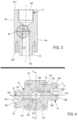
FIG. 3 shows a sectional view of the mixing unit ofFIG. 2 along line A-A, andFIG. 4 shows a sectional view of the mixing unit ofFIG. 2 along line B-B. -
FIG. 5 shows a side perspective view of a supply piece of the intensive mixing apparatus ofFIG. 1 . -
FIG. 6 shows a sectional view of the supply piece ofFIG. 5 along line A-A. - Now referring further to the figures, in which like numbers identify like elements,
FIG. 1 shows anintensive mixing apparatus 10 that forms part of a system for producing an elastomer-based masterbatch according to the method disclosed herein. The mixingapparatus 10 realizes continuous liquid mixing during a masterbatch production cycle, during which production cycle a composition is obtained according to a recipe that is selected from among a plurality of elastomeric composition recipes. The elastomeric composition is destined, for example, in the manufacture of tires and semi-finished products for tires (including but not limited to profiled products such as treads). As used herein, the terms "elastomer masterbatch composition", "elastomer-based masterbatch", "masterbatch composition" and "masterbatch" are interchangeable. As used herein, the terms "composition" and "composite" are interchangeable, each referring to the masterbatch composition that is produced by the disclosed invention throughout a production cycle (including an intermediate coagulum). - A system in which the
intensive mixing tool 10 is utilized includes at least one emulsion reservoir (not shown) for storing an elastomer emulsion in a liquid phase, as is known in the art of rubber mixing. The elastomer is selected from natural rubber, various synthetic elastomers (e.g., SBR, BR, etc.) and various elastomer blends. As used herein, the terms "elastomer emulsion" and "emulsion" are interchangeable. - This system also includes a slurry reservoir (not shown) for storing a solution in which filler particles are dispersed in an aqueous medium, as is known in the art of rubber mixing (as used herein, such as solution is referred to as "slurry solution", "slurry" or "solution of filler", which terms are deemed to be interchangeable). The filler is selected from one or more known materials, including, but not limited, to carbon black, silica, kaolin, chalk, synthesized organic charges, natural organic charges (e.g., wood fibers, cellulose fibers, etc.) and equivalents and combinations thereof. Thus, regardless of whether the slurry solution contains silica, neither the
intensive mixing tool 10 nor the system in which it is employed requires modification. - Still referring to
FIG. 1 and also toFIGS. 2 to 4 , theintensive mixing tool 10 is a tangential jet mixer that realizes a continuous liquid mixing process for producing a masterbatch composition. Theintensive mixing tool 10 includes a mixingunit 12 having acentral body 14 of predetermined height that is coextensive with aninlet extent 14a and anopposed outlet extent 14b (as used herein, the terms "central body", "mixing body", "mixing block" and "block" are interchangeable). Thecentral body 14 includes anexternal surface 14c that is coextensive with theinlet extent 14a and theoutlet extent 14b. An integral and generallycylindrical projection 16 that depends normally from theoutlet extent 14b of thecentral body 14 terminates in anegress extent 16a. - The central body also includes an annular inner wall surface 18 that defines a generally
cylindrical mixing chamber 20 of predetermined cross-sectional diameter relative to a central longitudinal axis of the mixing chamber (seeFIGS. 2 and3 ). The central longitudinal axis of the mixingbody 14 is coaxial relative to a central axis of the mixingchamber 20. The mixingchamber 20 has a predetermined length that is coextensive with aninlet extent 20a of the mixing chamber and theegress extent 16a of theprojection 16, thereby defining an uninterrupted fluid conduit therealong. In some embodiments of theintensive mixing tool 10, theinlet extent 20a of the mixingchamber 20 is disposed at or about midway along the predetermined length of thecentral body 14. - In the embodiment shown in the figures, the
external surface 14c of thecentral body 14 defines a generally quadrilateral geometry having atop surface 14c', an opposedbottom surface 14cb and fourside surfaces 14cs. A generally cylindrical injection inlet (or "inlet") 22 extends normally from each of a pair of opposed side surfaces 14cs such that a pair of injection inlets are located symmetrically and in opposing manner relative to the central longitudinal axis of the mixingbody 14. Eachinjector inlet 22 may be integral with thecentral body 14 or removably attached thereto via known attachment means (including, without limitation, corresponding threads, notches and recesses, friction fit and equivalents thereof). Such removable attachment may be desirable in the provision of a kit that includes thecentral body 14 with multiple injection outlets of various diameters and lengths that accommodate multiple rubber production installations. - As shown with respect to the embodiment of
FIGS. 1 to 4 , theinjector inlets 22 possess identical geometry with respect to one another. Each injector inlet has a generally cylindrical external geometry that includes aninjector ingress 22a via which the elastomer emulsion and the slurry solution enter the mixingunit 12. Eachinjector inlet 22 also includes asupply conduit 24 defined therein that establishes fluid communication between eachinjector ingress 22a and acorresponding injection conduit 26 in registry therewith. At least one recess may be defined at or adjacent eachinjector ingress 22a so as to accommodate a sealing member as is known in the art. As shown inFIG. 4 , such a recess is shown as atoroidal recess 22b. - Still referring to
FIGS. 1 to 4 , eachsupply conduit 24 includes a generallycylindrical entry portion 24a of predetermined length wherein the cross-sectional diameters of the entry portions are equal. Eachentry portion 24a leads into afeed portion 24b of the supply conduit having a generally frustoconical geometry with a predetermined extent that is coextensive with a base 24b' disposed adjacent therespective entry portion 24a and asummit 24b" disposed adjacent afeeding extent 26a of acorresponding injection conduit 26. A taperingwall 24w of eachfeed portion 24b is defined at a predetermined acute angle θ relative to a central axis of thesupply conduit 24 and thecorresponding injection conduit 26. In some embodiments, this angle θ is from about 30° to about 45° inclusive. Eachinjection conduit 26 has a predetermined length that is coextensive with itsfeeding extent 26a and anopposed delivery extent 26b that delivers a continuous flow from the corresponding supply conduit to the mixingchamber 20. Eachinjection conduit 26 also has a predetermined cross-sectional diameter that remains constant along the length thereof and that corresponds to a cross-sectional diameter of acorresponding summit 24b" of the feedingportion 24b of the supply conduit. - In this configuration, the
supply conduit 24 presents initially a constant cross-sectional diameter that stabilizes the incoming continuous flow along the predetermined length of theentry portion 24a. Thesupply conduit 24 presents thereafter a variable cross-sectional diameter along the predetermined extent of thefeed portion 24b such that the diameter of the feed portion is continuously reduced from the base 24b' to thesummit 24b". This reduction in diameter along the flow path of thesupply conduit 24 limits the effect of an undesirable pressure drop upon the energy that is converted during mixing of the two injected flows. Eachsupply conduit 24 feeds, to acorresponding injection conduit 26, a continuous flow from a reservoir in fluid communication with acorresponding injector ingress 22a. Oneinjector inlet 22, and particularly thesupply conduit 24 thereof, can be disposed in fluid communication with the emulsion reservoir so as to introduce a continuous flow of the elastomer emulsion therefrom into the mixingunit 12. Being in registry with thecorresponding injection conduit 26, thesupply conduit 24 introduces a continuous flow of the emulsion under pressure into the injection conduit for delivery to the mixingchamber 20. Similarly, theother injector inlet 22, and particularly thesupply conduit 24 thereof, can be disposed in fluid communication with the slurry reservoir so as to introduce a continuous flow of the slurry solution therefrom into the mixingunit 12. Being in registry with theinjection conduit 26, the supply conduit introduces a continuous flow of the slurry under pressure into the injection conduit for delivery to the mixingchamber 20 at the same time delivery of the emulsion to the mixing chamber is effected by thecorresponding injection conduit 26. Consequently, simultaneous injection of the emulsion and the slurry into the mixingchamber 20 forms a vortex therein. - It is understood that that the cross-sectional diameters of the supply conduits 24 (including the constant diameter of the
entry portions 24a and the variable diameter of thefeed portions 24b) and the cross-sectional diameter of theinjection conduits 26 may be adjusted as a function of the selected mixture recipe and/or the impact energy required upon combining the injected emulsion and slurry in the mixingchamber 20. Such dimensions are selected to ensure an inlet velocity and/or a pressure drop that converts a targeted amount of energy into mixing efficiency in the mixingchamber 20. - It is understood that alternative embodiments of the
intensive mixing tool 10 can include two pairs of generally cylindricaltangential injector inlets 22. For such embodiments, one pair ofinjector inlets 22, located symmetrically and in opposing manner relative to one another and relative to the central axis of thecentral body 14, facilitates injection of a continuous flow of the elastomer emulsion into the mixing unit 12 (and more particularly, the mixing chamber 20). Another pair ofinjector inlets 22, located symmetrically and in opposing manner relative to one another and relative to the central axis of thecentral body 14, facilitates injection of a continuous flow of the slurry solution into the mixing unit 12 (and more particularly, the mixing chamber 20). The injector inlets that facilitate injection of the slurry solution into the mixing chamber are normally offset from the injector inlets that inject the elastomer emulsion. During a production cycle, the two flows of the emulsion and the two flows of the slurry are injected separately but simultaneously into the mixingchamber 20 so as to form a vortex therein. - Still referring to
FIGS. 1 to 4 and also referring toFIGS. 5 and6 , theintensive mixing tool 10 includes asupply piece 28 that is detachably secured with eachinjector inlet 22 at arespective injector ingress 22a thereof. Thesupply piece 28 has a predetermined length coextensive with asupply extent 28a and anopposed delivery extent 28b of the supply piece. Thesupply extent 28a is in fluid communication with one of the emulsion reservoir and the slurry reservoir to facilitate uninterrupted delivery of a respective continuous flow to the mixingunit 12. Such fluid communication may be effected by one or more delivery conduits (not shown) and/or equivalent delivery means as is known in the art. - Each
supply piece 28 includes a generallyfrustoconical conduit 30 defined therein along the predetermined length of the supply piece 28 (seeFIG. 6 ). Theconduit 30 has a predetermined extent that is coextensive with thesupply extent 28a and thedelivery extent 28b of thesupply piece 28. In this configuration, theconduit 30 presents a variable cross-sectional diameter such that the diameter is continuously reduced from thesupply extent 28a (having a cross-sectional diameter commensurate with the cross-sectional diameter of a delivery conduit in fluid communication therewith) to thedelivery extent 28b (having a cross-sectional diameter commensurate with the cross-sectional diameter of theentry portion 24a of the supply conduit 24). The resulting stabilization of the incoming flow from the corresponding reservoir is realized upon entry into eachinjector inlet 22, thereby further limiting the effect of an undesirable pressure drop upon the energy that is converted during mixing of the two injected flows. It is understood that that the variable cross-sectional diameter of theconduit 30 of thesupply piece 28 may be adjusted as a function of the selected mixture recipe and/or the impact energy required upon combining the injected emulsion and slurry in the mixingchamber 20. Securement of eachsupply piece 28 with acorresponding injector inlet 22 may be effected by one or more known fasteners, including but not limited to fasteners 32 (seeFIG. 1 ). - Referring to
FIG. 1 and also toFIGS. 2 and3 , theintensive mixing tool 10 may include anoptional closure 34 that permits full access to the mixingchamber 20 of thecentral body 14. Theclosure 34 is disposed along thetop surface 14ct of thecentral body 14 and may be detachably affixed thereat. Theclosure 34 has a geometry that complements that of arecess 14d defined within thecentral body 14. Therecess 14d has a central axis that is coextensive with the central axes of thecentral body 14 and the mixingchamber 20. Therecess 14d establishes fluid communication with the mixingchamber 20 and facilitates the supply of one or more additives and/or other components thereto. Such additives include, but are not limited to, one or more solutions of ionic salts, one or more solutions of acid, one or more mineral or organic bases and one or more organic molecules (including silanes). Theclosure 34 may also accommodate the insertion of one or more sensors or probes (not shown) for generating ultrasound and/or for effecting one or more measurements as is known in the art (e.g., measurements of temperature and pressure, optical measurements, etc.). - Still referring to
FIG. 1 , theintensive mixing tool 10 can include amixture outlet 40 that is in detachable securement with thecentral body 14 so as to establish fluid communication therewith. Themixture outlet 40 includes an elongate cylindrical member of predetermined length that is coextensive with aningress extent 40a, disposed at or adjacent theegress extent 16a of theprojection 16, and anopposed egress extent 40b. Themixture outlet 40 includes aconduit 42 defined along the length thereof. In some embodiments, theconduit 42 may have a generally constant cross-sectional diameter therealong. In some other embodiments, theconduit 42 may have a varying cross-sectional diameter (i.e., divergent or convergent). For all such embodiments, theconduit 42 has a central axis that is coaxial with the central axes of thecentral body 14 and the mixingchamber 20, thereby ensuring an uninterrupted fluid path from therecess 14d through the mixingchamber 20 and through themixture outlet 40. A hose or equivalent conduit (not shown) may be fitted to theegress extent 40b of themixture outlet 40 to convey the masterbatch mixture toward one or more downstream rubber production installations while ensuring the filling of the mixingchamber 20. - As shown in
FIG. 1 , theintensive mixing tool 10 can additionally include one ormore securement flanges 50 that effect securement of the mixingunit 12 with themixture outlet 40. Securement may be effected by one ormore fasteners 55 as is known in the art and/or by equivalents thereof. Similarly, one or moreother securement flanges 50 may be employed that effect securement of theintensive mixing tool 10 with another element of a mixing installation in which the intensive mixing tool is employed (for example, a receptacle for receipt of the mixture that is conveyed from the mixture outlet 40). Securement may be effected by one ormore fasteners 57 as is known in the art and/or by equivalents thereof. It is understood thatflanges 50 and associatedfasteners mixture outlet 40 may be secured by an external pipe, hose and/or collar as is known in the art). - An exemplary method is now described that is performed by the
intensive mixing tool 10 for creating an elastomer-based masterbatch. The method includes a step of providing a system for producing an elastomer-filler masterbatch that includes theintensive mixing tool 10. Such a system also includes an elastomer emulsion stored in a liquid phase in an emulsion reservoir and a slurry solution stored in a liquid phase in a slurry reservoir. In the system, theintensive mixing tool 10 is provided in fluid communication with each of the emulsion reservoir and the slurry reservoir. In some embodiments of the method, the system includes an intensive mixing tool having two pairs ofinjector inlets 22. - The method also includes a step of introducing an elastomer emulsion as a continuous flow under pressure into one injector inlet (see arrow A of
FIG. 1 ). In embodiments of the method utilizing anintensive mixing tool 10 having two pairs of injector inlets, this step includes the step of introducing the elastomer emulsion as a continuous flow under pressure into each of a pair ofinjector inlets 22 located symmetrically and in opposing manner relative to one another and relative to the central axis of thecentral body 14. - The method further includes, during the step of introducing the elastomer emulsion, a step of simultaneously introducing a slurry solution as a continuous flow under pressure into the other injector inlet 22 (see arrow B of
FIG. 1 ). In embodiments of the method utilizing anintensive mixing tool 10 having two pairs of injector inlets, this step includes the step of introducing the slurry solution as a continuous flow under pressure into another pair ofinjector inlets 22. The second pair of injector inlets is located symmetrically and in opposing manner relative to one another and relative to the central axis of thecentral body 14, and they are normally offset from the injector inlets that inject the elastomer emulsion. - For rapid and concentrated coagulation, some embodiments of the method employ, during the step of simultaneously introducing the slurry solution, a solution of dispersed (structured or spherical) aqueous silica with silica concentrations greater than > 5%. For some of these embodiments, the silica concentration is at or about 20%.
- During the steps of introducing the elastomer emulsion and simultaneously introducing the slurry solution, the respective flows are injected into the mixing
chamber 20 by theinjection conduits 26. As a result, the injected flows impinge upon one another, forming a vortex and obtaining a flow of coagulated material therefrom that is the masterbatch. A turbulence zone between the two fluids is conducive to mixing which ends with coagulation in the diffuser forming a cylindrical viscoelastic solid. The introduction of each flow into the mixingchamber 20 is generally carried out continuously so as to preserve the uniformity of the contact between the emulsion and the slurry solution. - In prior art mixing methods, cavitation often limits the rate at which turbulence can be induced. As disclosed herein, the use of the
intensive mixing tool 10 enables the simultaneous acceleration of both the emulsion and the slurry. The comparable acceleration of the shearing level of the emulsion and slurry flows enhances the mixing efficiency at a molecular level. - In an embodiment of the disclosed method, the method also includes a step of introducing at least one salt during the step of simultaneously introducing the slurry solution.
- In another embodiment of the method, the method also includes a step of blending the masterbatch with one or more additional components. Such components can be selected from one or more antioxidants, sulfur, one or more resins, one or more catalysts, one or more coupling agents, one or more elastomer composites and any equivalent and combination thereof.
- In a method for making one or more tire products, the process includes the steps of preparing an elastomer-based masterbatch according to the method disclosed herein. The masterbatch is prepared as a vulcanizable compound that is vulcanized in a subsequent step to form the one or more tire products.
- Thus, a process for creating an elastomer-based masterbatch in the context of rapid chemical reactions may be summarized as follows:
- A tangential mixer geometry is applied to the liquid mixing of lattices and charge suspensions (carbon black, silica, etc.) in order to achieve their coagulation. Coagulation may be caused by, or alternatively affected by, the optional addition of one or more additives (e.g., one or more of at least one ionic salt, at least one organic molecule, at least one acid/base combination, etc.).
- In realizing the described process, one can obtain the same level of homogeneity (e.g., a coefficient of variation (CoV) at or around 0.05) in a typical mixing time of the same order under milder conditions (e.g., 20-30 m/s instead of 45-80 m/s). Consequently, a more moderate pressure drop is generated (e.g., less than 10 bar instead of 20 bar).
- As used herein, the term "method" or "process" may include one or more steps performed at least by one electronic or computer-based apparatus having a processor for executing instructions that carry out the steps.
- The terms "at least one" and "one or more" are used interchangeably. Ranges that are described as being "between a and b" are inclusive of the values for "a" and "b."
- While particular embodiments of the disclosed apparatus have been illustrated and described, it will be understood that various changes, additions and modifications can be made without departing from the spirit and scope of the present disclosure. Accordingly, no limitation should be imposed on the scope of the presently disclosed invention, except as set forth in the accompanying claims.
Claims (12)
- A system for producing an elastomer-filler masterbatch, the system comprising:an elastomer emulsion stored in a liquid phase in an emulsion reservoir;a slurry solution stored in a liquid phase in a slurry reservoir;an intensive mixing tool (10) in fluid communication with each of the emulsion reservoir and the slurry reservoir, the intensive mixing tool comprising:an intensive mixing unit (12) having a central body (14) of predetermined height that is coextensive with an inlet extent (14a) and an opposed outlet extent (14b), the central body (14) including an external quadrilateral surface (14c) and an annular inner wall surface (18) that defines a generally cylindrical mixing chamber (20) of predetermined cross-sectional diameter relative to a central axis of the mixing chamber and having a central axis that is coaxial with a central axis of the mixing body (14), the mixing chamber (20) having a predetermined length that is coextensive with an inlet extent (20a) of the mixing chamber and an egress extent (16a) of an integral and generally cylindrical projection (16) that depends normally from the outlet extent (14b) of the central body (14), characterized byan injector inlet (22) that extends normally from each of a pair of opposed side surfaces (14c) of the central body such that at least a pair of injection inlets are located symmetrically and in opposing manner relative to a central axis of the central body, each injector inlet (22) including a supply conduit (24) defined therein that establishes fluid communication between an injector ingress (22a) via which one of an elastomer emulsion and a slurry solution enter the mixing unit (12) and a corresponding injection conduit (26) in registry therewith, each injector inlet establishing fluid communication between one of an elastomer emulsion reservoir from which a predetermined volume of the emulsion is introduced as a continuous flow under pressure, and a slurry solution reservoir from which a predetermined volume of the slurry is introduced as a continuous flow under pressure such that simultaneous injection of the elastomer emulsion and the slurry solution into the mixing chamber forms a vortex therein; anda supply piece (28) that is detachably secured with each injector inlet (22) at a respective injector ingress (22a) thereof, the supply piece (28) having a predetermined length coextensive with a supply extent (28a) and a delivery extent (28b) of the supply piece, and the supply piece being in fluid communication with one of the emulsion reservoir and the slurry reservoir to facilitate uninterrupted delivery of a respective continuous flow to the mixing unit (12), the supply piece having a generally frustoconical conduit (30) defined therein that is coextensive with the supply extent (28a) and the delivery extent (28b) of the supply piece, the conduit (30) of the supply piece having a variable cross-sectional diameter from the supply extent (28a) of the supply piece, at which the conduit of the supply piece has a cross-sectional diameter commensurate with a cross-sectional diameter of a delivery conduit in fluid communication therewith, to the delivery extent (28b) of the supply piece, having a cross-sectional diameter commensurate with the cross-sectional diameter of the feed section (24b) of the supply conduit (24).
- The system of claim 1, wherein:each supply conduit (24) includes a generally cylindrical entry portion (24a) of predetermined length that feeds into a feed portion (24b) of the supply conduit with the feed portion having a generally frustoconical geometry with a predetermined extent that is coextensive with a base (24b') disposed adjacent the entry portion (24a) and a summit (24b") disposed adjacent a feeding extent (26a) of a corresponding injection conduit (26), and a tapering wall (24w) of each feed portion is defined at a predetermined acute angle (θ) relative to a central axis of the supply conduit and the corresponding injection conduit; andeach injection conduit (26) includes a predetermined length that is coextensive with its feeding extent and an opposed delivery extent (26b) that delivers a continuous flow from the corresponding supply conduit to the mixing chamber (20), each injection conduit (26) having a predetermined cross-sectional diameter that remains constant along the length thereof and that corresponds to a cross-sectional diameter of a corresponding summit (24b") of the feed portion (24b) of the supply conduit.
- The system of claim 2, wherein the angle (θ) is from about 30° to about 45° inclusive.
- The system of any of claims 1 to 3, wherein the injection inlet (22) of the intensive mixing tool (10) includes a recess defined proximate each injector ingress (22) so as to accommodate a sealing member thereby.
- The system of any of claims 1 to 4, wherein the intensive mixing tool (10) further comprises a mixture outlet (40) in detachable securement with the central body (14) so as to establish fluid communication therewith, the mixture outlet including an elongate cylindrical member of predetermined length that is coextensive with an ingress extent (40a) disposed at or adjacent the egress extent (16a) of the projection (16), and an opposed egress extent (40b), the mixture outlet also including a generally cylindrical conduit (42) defined along the length thereof and having a constant cross-sectional diameter.
- The system of any of claims 1 to 5, wherein the central body (14) of the intensive mixing tool (10) includes a recess (14d) defined within the central body that establishes fluid communication with the mixing chamber (20), the recess having a central axis that is coextensive with the central axes of the central body (14) and the mixing chamber (20).
- The system of claim 6, wherein the intensive mixing tool (10) further comprises a closure (34) disposed along a top surface (14ct) of the central body and having a geometry that complements insertion of the closure therein.
- The system of any of claims 1 to 7, wherein:the elastomer emulsion comprises an elastomer selected from at least one of natural rubber, at least one synthetic elastomer and one or more elastomer blends; andthe slurry solution comprises a solution in which filler particles are dispersed in an aqueous medium, and the filler is selected from at least one of carbon black, silica, kaolin, chalk, synthesized organic charges, natural organic charges, and equivalents and combinations thereof.
- The system of any of claims 1 to 8, wherein the central body of intensive mixing tool (10) includes two pairs of generally cylindrical tangential injector inlets (22), with one pair of injector inlets located symmetrically and in opposing manner relative to one another and relative to the central axis of the central body (14) so as to inject a continuous flow of the elastomer emulsion into the mixing chamber, and with another pair of injector inlets (22), located symmetrically and in opposing manner relative to one another and relative to the central axis of the central body (14) so as to inject a continuous flow of the slurry into the mixing chamber, with the injector inlets that inject the slurry into the mixing chamber being normally offset from the injector inlets that inject the emulsion.
- A method of producing an elastomer-filler masterbatch, comprising the following steps:providing a system according to any of claims 1 to 9;introducing the elastomer emulsion into at least one injector inlet (22) as a continuous flow under pressure;introducing the slurry solution into at least one other injector inlet (22) as a continuous flow under pressure; andsimultaneously injecting a predetermined volume of the elastomer emulsion and a predetermined volume of the slurry solution into the mixing chamber such that the separately injected flows impinge upon one another and form a vortex in the mixing chamber to obtain a flow of coagulated material therefrom that is the masterbatch.
- The method of claim 10, further comprising the step of introducing at least one salt during the step of simultaneously injecting the elastomer emulsion and the slurry solution into the mixing chamber (20).
- The method of claim 10 or claim 11, further comprising, during the step of simultaneously injecting the elastomer emulsion and the slurry solution into the mixing chamber, the step of introducing one or more components selected from one or more antioxidants, sulfur, one or more resins, one or more catalysts, one or more coupling agents, one or more elastomer composites and any equivalent and combination thereof.
Applications Claiming Priority (2)
| Application Number | Priority Date | Filing Date | Title |
|---|---|---|---|
| FR1903830 | 2019-04-10 | ||
| PCT/EP2020/060128 WO2020208130A1 (en) | 2019-04-10 | 2020-04-09 | Intensive mixing tool for producing elastomer-based composites |
Publications (2)
| Publication Number | Publication Date |
|---|---|
| EP3953027A1 EP3953027A1 (en) | 2022-02-16 |
| EP3953027B1 true EP3953027B1 (en) | 2024-07-03 |
Family
ID=68072549
Family Applications (1)
| Application Number | Title | Priority Date | Filing Date |
|---|---|---|---|
| EP20718303.9A Active EP3953027B1 (en) | 2019-04-10 | 2020-04-09 | Intensive mixing tool for producing elastomer-based composites |
Country Status (3)
| Country | Link |
|---|---|
| EP (1) | EP3953027B1 (en) |
| CN (1) | CN113646069B (en) |
| WO (1) | WO2020208130A1 (en) |
Families Citing this family (1)
| Publication number | Priority date | Publication date | Assignee | Title |
|---|---|---|---|---|
| CN115434397B (en) * | 2022-10-14 | 2026-02-06 | 浙江怡和卫浴有限公司 | Built-in foam generating device and intelligent closestool |
Family Cites Families (7)
| Publication number | Priority date | Publication date | Assignee | Title |
|---|---|---|---|---|
| DE1493663C3 (en) * | 1964-05-30 | 1975-01-09 | Farbwerke Hoechst Ag, Vormals Meister Lucius & Bruening, 6000 Frankfurt | Process and device for the production of alkali salts of aromatic hydroxy compounds |
| TW360585B (en) * | 1996-04-01 | 1999-06-11 | Cabot Corp | Elastomeric compositions and methods and apparatus for producing same |
| CN1250312C (en) * | 2001-05-05 | 2006-04-12 | 阿山特斯有限公司 | Formation of small crystals |
| US6601986B2 (en) * | 2001-08-29 | 2003-08-05 | Taiwan Semiconductor Manufacturing Co., Ltd | Fluid mixing apparatus |
| FR2976574B1 (en) | 2011-06-17 | 2013-05-31 | Rhodia Operations | COMPOSITION BASED ON OXIDES OF CERIUM, ZIRCONIUM AND ANOTHER RARE EARTH WITH HIGH REDUCIBILITY, PROCESS FOR PREPARATION AND USE IN THE CATALYSIS FIELD. |
| WO2017011548A1 (en) * | 2015-07-15 | 2017-01-19 | Cabot Corporation | Methods of making an elastomer composite reinforced with silica and products containing same |
| RU2730831C2 (en) * | 2015-12-04 | 2020-08-26 | Пирелли Тайр С.П.А. | Method of producing an elastomeric composition |
-
2020
- 2020-04-09 WO PCT/EP2020/060128 patent/WO2020208130A1/en not_active Ceased
- 2020-04-09 CN CN202080026479.XA patent/CN113646069B/en active Active
- 2020-04-09 EP EP20718303.9A patent/EP3953027B1/en active Active
Also Published As
| Publication number | Publication date |
|---|---|
| EP3953027A1 (en) | 2022-02-16 |
| CN113646069B (en) | 2023-09-22 |
| CN113646069A (en) | 2021-11-12 |
| WO2020208130A1 (en) | 2020-10-15 |
Similar Documents
| Publication | Publication Date | Title |
|---|---|---|
| ES2246847T3 (en) | PROCEDURES AND APPLIANCES TO PRODUCE AND TREAT NOVEDOUS ELASTOMEROS COMPOUNDS. | |
| EP2478043B1 (en) | Formation of latex coagulum composite | |
| US7582688B2 (en) | Elastomer composites, method and apparatus | |
| KR100617997B1 (en) | Elastomer Composite Blends and Their Manufacturing Methods | |
| EP0892705A2 (en) | Novel elastomer composites, method and apparatus | |
| CN108026288B (en) | Method and apparatus for producing a rubber compound in liquid phase | |
| JP6669851B2 (en) | Method for producing silica-reinforced elastomer composites and articles containing same | |
| EP3953027A1 (en) | Intensive mixing tool for producing elastomer-based composites | |
| KR100477497B1 (en) | Novel Elastomer Composites, Method and Apparatus | |
| EP4530306A1 (en) | Masterbatch production process | |
| US20250101189A1 (en) | Masterbatch production system and method |
Legal Events
| Date | Code | Title | Description |
|---|---|---|---|
| STAA | Information on the status of an ep patent application or granted ep patent |
Free format text: STATUS: UNKNOWN |
|
| STAA | Information on the status of an ep patent application or granted ep patent |
Free format text: STATUS: THE INTERNATIONAL PUBLICATION HAS BEEN MADE |
|
| PUAI | Public reference made under article 153(3) epc to a published international application that has entered the european phase |
Free format text: ORIGINAL CODE: 0009012 |
|
| STAA | Information on the status of an ep patent application or granted ep patent |
Free format text: STATUS: REQUEST FOR EXAMINATION WAS MADE |
|
| 17P | Request for examination filed |
Effective date: 20211110 |
|
| AK | Designated contracting states |
Kind code of ref document: A1 Designated state(s): AL AT BE BG CH CY CZ DE DK EE ES FI FR GB GR HR HU IE IS IT LI LT LU LV MC MK MT NL NO PL PT RO RS SE SI SK SM TR |
|
| DAV | Request for validation of the european patent (deleted) | ||
| DAX | Request for extension of the european patent (deleted) | ||
| REG | Reference to a national code |
Ref country code: DE Ref legal event code: R079 Free format text: PREVIOUS MAIN CLASS: B01F0005000000 Ipc: B01F0025100000 Ref country code: DE Ref legal event code: R079 Ref document number: 602020033300 Country of ref document: DE Free format text: PREVIOUS MAIN CLASS: B01F0005000000 Ipc: B01F0025100000 |
|
| GRAP | Despatch of communication of intention to grant a patent |
Free format text: ORIGINAL CODE: EPIDOSNIGR1 |
|
| STAA | Information on the status of an ep patent application or granted ep patent |
Free format text: STATUS: GRANT OF PATENT IS INTENDED |
|
| RIC1 | Information provided on ipc code assigned before grant |
Ipc: B29B 7/90 20060101ALI20240222BHEP Ipc: B29B 7/76 20060101ALI20240222BHEP Ipc: B29B 7/74 20060101ALI20240222BHEP Ipc: B01F 25/10 20220101AFI20240222BHEP |
|
| INTG | Intention to grant announced |
Effective date: 20240325 |
|
| GRAS | Grant fee paid |
Free format text: ORIGINAL CODE: EPIDOSNIGR3 |
|
| GRAA | (expected) grant |
Free format text: ORIGINAL CODE: 0009210 |
|
| STAA | Information on the status of an ep patent application or granted ep patent |
Free format text: STATUS: THE PATENT HAS BEEN GRANTED |
|
| AK | Designated contracting states |
Kind code of ref document: B1 Designated state(s): AL AT BE BG CH CY CZ DE DK EE ES FI FR GB GR HR HU IE IS IT LI LT LU LV MC MK MT NL NO PL PT RO RS SE SI SK SM TR |
|
| REG | Reference to a national code |
Ref country code: CH Ref legal event code: EP |
|
| REG | Reference to a national code |
Ref country code: DE Ref legal event code: R096 Ref document number: 602020033300 Country of ref document: DE |
|
| REG | Reference to a national code |
Ref country code: LT Ref legal event code: MG9D |
|
| REG | Reference to a national code |
Ref country code: NL Ref legal event code: MP Effective date: 20240703 |
|
| PG25 | Lapsed in a contracting state [announced via postgrant information from national office to epo] |
Ref country code: PT Free format text: LAPSE BECAUSE OF FAILURE TO SUBMIT A TRANSLATION OF THE DESCRIPTION OR TO PAY THE FEE WITHIN THE PRESCRIBED TIME-LIMIT Effective date: 20241104 |
|
| REG | Reference to a national code |
Ref country code: AT Ref legal event code: MK05 Ref document number: 1699250 Country of ref document: AT Kind code of ref document: T Effective date: 20240703 |
|
| PG25 | Lapsed in a contracting state [announced via postgrant information from national office to epo] |
Ref country code: NL Free format text: LAPSE BECAUSE OF FAILURE TO SUBMIT A TRANSLATION OF THE DESCRIPTION OR TO PAY THE FEE WITHIN THE PRESCRIBED TIME-LIMIT Effective date: 20240703 |
|
| PG25 | Lapsed in a contracting state [announced via postgrant information from national office to epo] |
Ref country code: PT Free format text: LAPSE BECAUSE OF FAILURE TO SUBMIT A TRANSLATION OF THE DESCRIPTION OR TO PAY THE FEE WITHIN THE PRESCRIBED TIME-LIMIT Effective date: 20241104 Ref country code: NL Free format text: LAPSE BECAUSE OF FAILURE TO SUBMIT A TRANSLATION OF THE DESCRIPTION OR TO PAY THE FEE WITHIN THE PRESCRIBED TIME-LIMIT Effective date: 20240703 |
|
| PG25 | Lapsed in a contracting state [announced via postgrant information from national office to epo] |
Ref country code: NO Free format text: LAPSE BECAUSE OF FAILURE TO SUBMIT A TRANSLATION OF THE DESCRIPTION OR TO PAY THE FEE WITHIN THE PRESCRIBED TIME-LIMIT Effective date: 20241003 |
|
| PG25 | Lapsed in a contracting state [announced via postgrant information from national office to epo] |
Ref country code: FI Free format text: LAPSE BECAUSE OF FAILURE TO SUBMIT A TRANSLATION OF THE DESCRIPTION OR TO PAY THE FEE WITHIN THE PRESCRIBED TIME-LIMIT Effective date: 20240703 Ref country code: PL Free format text: LAPSE BECAUSE OF FAILURE TO SUBMIT A TRANSLATION OF THE DESCRIPTION OR TO PAY THE FEE WITHIN THE PRESCRIBED TIME-LIMIT Effective date: 20240703 Ref country code: GR Free format text: LAPSE BECAUSE OF FAILURE TO SUBMIT A TRANSLATION OF THE DESCRIPTION OR TO PAY THE FEE WITHIN THE PRESCRIBED TIME-LIMIT Effective date: 20241004 |
|
| PG25 | Lapsed in a contracting state [announced via postgrant information from national office to epo] |
Ref country code: BG Free format text: LAPSE BECAUSE OF FAILURE TO SUBMIT A TRANSLATION OF THE DESCRIPTION OR TO PAY THE FEE WITHIN THE PRESCRIBED TIME-LIMIT Effective date: 20240703 |
|
| PG25 | Lapsed in a contracting state [announced via postgrant information from national office to epo] |
Ref country code: LV Free format text: LAPSE BECAUSE OF FAILURE TO SUBMIT A TRANSLATION OF THE DESCRIPTION OR TO PAY THE FEE WITHIN THE PRESCRIBED TIME-LIMIT Effective date: 20240703 |
|
| PG25 | Lapsed in a contracting state [announced via postgrant information from national office to epo] |
Ref country code: IS Free format text: LAPSE BECAUSE OF FAILURE TO SUBMIT A TRANSLATION OF THE DESCRIPTION OR TO PAY THE FEE WITHIN THE PRESCRIBED TIME-LIMIT Effective date: 20241103 Ref country code: AT Free format text: LAPSE BECAUSE OF FAILURE TO SUBMIT A TRANSLATION OF THE DESCRIPTION OR TO PAY THE FEE WITHIN THE PRESCRIBED TIME-LIMIT Effective date: 20240703 |
|
| PG25 | Lapsed in a contracting state [announced via postgrant information from national office to epo] |
Ref country code: CZ Free format text: LAPSE BECAUSE OF FAILURE TO SUBMIT A TRANSLATION OF THE DESCRIPTION OR TO PAY THE FEE WITHIN THE PRESCRIBED TIME-LIMIT Effective date: 20240703 Ref country code: HR Free format text: LAPSE BECAUSE OF FAILURE TO SUBMIT A TRANSLATION OF THE DESCRIPTION OR TO PAY THE FEE WITHIN THE PRESCRIBED TIME-LIMIT Effective date: 20240703 |
|
| PG25 | Lapsed in a contracting state [announced via postgrant information from national office to epo] |
Ref country code: RS Free format text: LAPSE BECAUSE OF FAILURE TO SUBMIT A TRANSLATION OF THE DESCRIPTION OR TO PAY THE FEE WITHIN THE PRESCRIBED TIME-LIMIT Effective date: 20241003 Ref country code: ES Free format text: LAPSE BECAUSE OF FAILURE TO SUBMIT A TRANSLATION OF THE DESCRIPTION OR TO PAY THE FEE WITHIN THE PRESCRIBED TIME-LIMIT Effective date: 20240703 |
|
| PG25 | Lapsed in a contracting state [announced via postgrant information from national office to epo] |
Ref country code: RS Free format text: LAPSE BECAUSE OF FAILURE TO SUBMIT A TRANSLATION OF THE DESCRIPTION OR TO PAY THE FEE WITHIN THE PRESCRIBED TIME-LIMIT Effective date: 20241003 Ref country code: PL Free format text: LAPSE BECAUSE OF FAILURE TO SUBMIT A TRANSLATION OF THE DESCRIPTION OR TO PAY THE FEE WITHIN THE PRESCRIBED TIME-LIMIT Effective date: 20240703 Ref country code: NO Free format text: LAPSE BECAUSE OF FAILURE TO SUBMIT A TRANSLATION OF THE DESCRIPTION OR TO PAY THE FEE WITHIN THE PRESCRIBED TIME-LIMIT Effective date: 20241003 Ref country code: LV Free format text: LAPSE BECAUSE OF FAILURE TO SUBMIT A TRANSLATION OF THE DESCRIPTION OR TO PAY THE FEE WITHIN THE PRESCRIBED TIME-LIMIT Effective date: 20240703 Ref country code: IS Free format text: LAPSE BECAUSE OF FAILURE TO SUBMIT A TRANSLATION OF THE DESCRIPTION OR TO PAY THE FEE WITHIN THE PRESCRIBED TIME-LIMIT Effective date: 20241103 Ref country code: HR Free format text: LAPSE BECAUSE OF FAILURE TO SUBMIT A TRANSLATION OF THE DESCRIPTION OR TO PAY THE FEE WITHIN THE PRESCRIBED TIME-LIMIT Effective date: 20240703 Ref country code: GR Free format text: LAPSE BECAUSE OF FAILURE TO SUBMIT A TRANSLATION OF THE DESCRIPTION OR TO PAY THE FEE WITHIN THE PRESCRIBED TIME-LIMIT Effective date: 20241004 Ref country code: FI Free format text: LAPSE BECAUSE OF FAILURE TO SUBMIT A TRANSLATION OF THE DESCRIPTION OR TO PAY THE FEE WITHIN THE PRESCRIBED TIME-LIMIT Effective date: 20240703 Ref country code: ES Free format text: LAPSE BECAUSE OF FAILURE TO SUBMIT A TRANSLATION OF THE DESCRIPTION OR TO PAY THE FEE WITHIN THE PRESCRIBED TIME-LIMIT Effective date: 20240703 Ref country code: CZ Free format text: LAPSE BECAUSE OF FAILURE TO SUBMIT A TRANSLATION OF THE DESCRIPTION OR TO PAY THE FEE WITHIN THE PRESCRIBED TIME-LIMIT Effective date: 20240703 Ref country code: BG Free format text: LAPSE BECAUSE OF FAILURE TO SUBMIT A TRANSLATION OF THE DESCRIPTION OR TO PAY THE FEE WITHIN THE PRESCRIBED TIME-LIMIT Effective date: 20240703 Ref country code: AT Free format text: LAPSE BECAUSE OF FAILURE TO SUBMIT A TRANSLATION OF THE DESCRIPTION OR TO PAY THE FEE WITHIN THE PRESCRIBED TIME-LIMIT Effective date: 20240703 |
|
| REG | Reference to a national code |
Ref country code: DE Ref legal event code: R097 Ref document number: 602020033300 Country of ref document: DE |
|
| PG25 | Lapsed in a contracting state [announced via postgrant information from national office to epo] |
Ref country code: DK Free format text: LAPSE BECAUSE OF FAILURE TO SUBMIT A TRANSLATION OF THE DESCRIPTION OR TO PAY THE FEE WITHIN THE PRESCRIBED TIME-LIMIT Effective date: 20240703 Ref country code: RO Free format text: LAPSE BECAUSE OF FAILURE TO SUBMIT A TRANSLATION OF THE DESCRIPTION OR TO PAY THE FEE WITHIN THE PRESCRIBED TIME-LIMIT Effective date: 20240703 Ref country code: SM Free format text: LAPSE BECAUSE OF FAILURE TO SUBMIT A TRANSLATION OF THE DESCRIPTION OR TO PAY THE FEE WITHIN THE PRESCRIBED TIME-LIMIT Effective date: 20240703 |
|
| PG25 | Lapsed in a contracting state [announced via postgrant information from national office to epo] |
Ref country code: EE Free format text: LAPSE BECAUSE OF FAILURE TO SUBMIT A TRANSLATION OF THE DESCRIPTION OR TO PAY THE FEE WITHIN THE PRESCRIBED TIME-LIMIT Effective date: 20240703 |
|
| PG25 | Lapsed in a contracting state [announced via postgrant information from national office to epo] |
Ref country code: SK Free format text: LAPSE BECAUSE OF FAILURE TO SUBMIT A TRANSLATION OF THE DESCRIPTION OR TO PAY THE FEE WITHIN THE PRESCRIBED TIME-LIMIT Effective date: 20240703 Ref country code: IT Free format text: LAPSE BECAUSE OF FAILURE TO SUBMIT A TRANSLATION OF THE DESCRIPTION OR TO PAY THE FEE WITHIN THE PRESCRIBED TIME-LIMIT Effective date: 20240703 |
|
| PLBE | No opposition filed within time limit |
Free format text: ORIGINAL CODE: 0009261 |
|
| STAA | Information on the status of an ep patent application or granted ep patent |
Free format text: STATUS: NO OPPOSITION FILED WITHIN TIME LIMIT |
|
| 26N | No opposition filed |
Effective date: 20250404 |
|
| PGFP | Annual fee paid to national office [announced via postgrant information from national office to epo] |
Ref country code: DE Payment date: 20250422 Year of fee payment: 6 |
|
| PGFP | Annual fee paid to national office [announced via postgrant information from national office to epo] |
Ref country code: FR Payment date: 20250425 Year of fee payment: 6 |
|
| PG25 | Lapsed in a contracting state [announced via postgrant information from national office to epo] |
Ref country code: SE Free format text: LAPSE BECAUSE OF FAILURE TO SUBMIT A TRANSLATION OF THE DESCRIPTION OR TO PAY THE FEE WITHIN THE PRESCRIBED TIME-LIMIT Effective date: 20240703 |
|
| REG | Reference to a national code |
Ref country code: CH Ref legal event code: H13 Free format text: ST27 STATUS EVENT CODE: U-0-0-H10-H13 (AS PROVIDED BY THE NATIONAL OFFICE) Effective date: 20251125 |
|
| PG25 | Lapsed in a contracting state [announced via postgrant information from national office to epo] |
Ref country code: LU Free format text: LAPSE BECAUSE OF NON-PAYMENT OF DUE FEES Effective date: 20250409 |
|
| PG25 | Lapsed in a contracting state [announced via postgrant information from national office to epo] |
Ref country code: MC Free format text: LAPSE BECAUSE OF FAILURE TO SUBMIT A TRANSLATION OF THE DESCRIPTION OR TO PAY THE FEE WITHIN THE PRESCRIBED TIME-LIMIT Effective date: 20240703 |
|
| GBPC | Gb: european patent ceased through non-payment of renewal fee |
Effective date: 20250409 |
|
| REG | Reference to a national code |
Ref country code: BE Ref legal event code: MM Effective date: 20250430 |
|
| PG25 | Lapsed in a contracting state [announced via postgrant information from national office to epo] |
Ref country code: GB Free format text: LAPSE BECAUSE OF NON-PAYMENT OF DUE FEES Effective date: 20250409 |
|
| PG25 | Lapsed in a contracting state [announced via postgrant information from national office to epo] |
Ref country code: BE Free format text: LAPSE BECAUSE OF NON-PAYMENT OF DUE FEES Effective date: 20250430 |
|
| PG25 | Lapsed in a contracting state [announced via postgrant information from national office to epo] |
Ref country code: CH Free format text: LAPSE BECAUSE OF NON-PAYMENT OF DUE FEES Effective date: 20250430 |
|
| PG25 | Lapsed in a contracting state [announced via postgrant information from national office to epo] |
Ref country code: IE Free format text: LAPSE BECAUSE OF NON-PAYMENT OF DUE FEES Effective date: 20250409 |